
Related Manuals for WAGO 750 XTR Series


Summary of Contents for WAGO 750 XTR Series
- Page 1 WAGO I/O System 750 XTR System manual 750 XTR: Guidelines and recommendations for increasing operational safety 750 XTR Series System manual | Version 2.0.0...
- Page 2 We wish to point out that the software and hardware terms as well as the trademarks of companies used and/or mentioned in the present manual are generally protected by trademark or patent. WAGO is a registered trademark of WAGO Verwaltungsgesellschaft mbH. System manual | Version: 2.0.0...
-
Page 3: Table Of Contents
750 XTR Series Table of Contents Table of Contents Provisions......................... 5 Intended Use ...................... 6 Typographical Conventions.................. 7 Legal Information .................... 8 Safety .......................... 10 General Safety Regulations .................. 10 Electrical Safety..................... 10 Mechanical Safety .................... 11 Thermal Safety ...................... 11 Indirect Safety ....................... 12 System Features ...................... 13... - Page 4 Table of Contents 750 XTR Series Data Security .................... 40 5.2.8 Designing the System Supply ................ 42 Field Supply Layout.................... 42 Special Applications and Environments ............... 43 Marine, On-/Offshore, Substation Instrumentation and Control, Telecontrol 5.5.1 Technology, Railway Engineering .............. 43 Ex i XTR Applications ...................
-
Page 5: Provisions
Provisions This document applies to the I/O system: WAGO I/O System 750 XTR (Series 750 XTR. The complete operating instructions for the I/O system consists of several documents. The I/O system must only be installed and operated in accordance with the complete operating instructions. -
Page 6: Intended Use
The terms set forth in the General Business & Contract Conditions for Delivery and Ser- vice of WAGO GmbH & Co. KG and the terms for software products and products with in- tegrated software stated in the WAGO Software License Contract – both available at ü www.wago.com... - Page 7 750 XTR Series Provisions 1.2 Typographical Conventions Number Notation Decimals: Normal notation 0x64 Hexadecimals: C-notation ‘100’ Binary: In single quotation marks ‘0110.0100’ Nibbles separated by a period Text Formatting italic Names of paths or files bold Menu items, entry or selection fields, emphasis...
-
Page 8: Legal Information
Third-party products are always mentioned without any reference to patent rights. WAGO GmbH & Co. KG, or for third-party prod- ucts, their manufacturer, retain all rights regarding patent, utility model or design registra- tion. - Page 9 WAGO GmbH & Co. KG retains the right to carry out technical changes and improvements of the products and the data, specifications and illustrations of this manual.
-
Page 10: Safety
Safety 750 XTR Series Safety 2.1 General Safety Regulations • This documentation is part of the Products. Retain the documentation for the entire service life of the Products. Pass on the documentation to any subsequent user of the Products. In addition, ensure that any supplement to this documentation is included, if necessary. -
Page 11: Mechanical Safety
• Without overcurrent protection, the electronics can be damaged. Provide appropriate protection. • Disable the voltage and field supply before inserting/replacing fuses. • Only use fuses that meet WAGO specifications. • For UL-approved systems, use fuses with UL approval only . Cables •... -
Page 12: Indirect Safety
• Do not place products on the data or power jumper contacts. • If product fails, communication to downstream products may be interrupted. • Products from the WAGO I/O System 750/753 can be operated in combination with those of the WAGO I/O System 750 XTR. Note the special power supply requirements! Such mixed operation does not change the maximum permissible ambient conditions of the individual products. -
Page 13: System Features
750 XTR Series System Features System Features 3.1 Component Structure 3.1.1 Designs Figure 1: Example Head Station Housings The housings of head stations (fieldbus couplers or controllers) may differ, for instance in terms of: • The connection level • The operator control elements and indicators •... -
Page 14: Structure Of The Head Stations
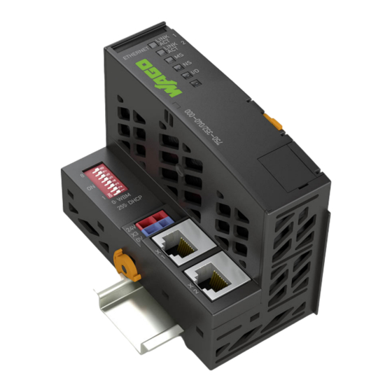
System Features 750 XTR Series 3.1.2 Structure of the Head Stations Example View of PFC Figure 3: Example View of PFC & Product Manual Reset button 8 System Contacts [} 22] Data contacts & Product Manual Indicators: power supply status & Product Manual Indicators: system status ®... - Page 15 750 XTR Series System Features Example View of the Fieldbus Coupler/Controller Figure 4: Example View of the Controller Slot for Mini-WSB (optional) 8 Marking Elements [} 24] 8 Versions [} 18] 8 System Contacts [} 22] Data contacts & Product Manual Indicators: power supply status & Product Manual Indicators: fieldbus status ®...
-
Page 16: I/O Module Configuration
System Features 750 XTR Series 3.1.3 I/O Module Configuration ® Example View of the I/O Module in the 8-Channel Housing (CAGE CLAMP Connections) ® Figure 5: Example View of I/O Module with CAGE CLAMP Connections 8 Marking Elements [} 24] Slot for Mini-WSB (optional) 8 Versions [} 18]... - Page 17 750 XTR Series System Features Example View of the I/O Module in the 16-Channel Housing (Push-in CAGE ® CLAMP -Connections) ® Figure 6: Example View of I/O Module with Push-in CAGE CLAMP Connections Slot for Mini-WSB (optional) 8 Marking Elements [} 24] 8 Versions [} 18] 8 System Contacts [} 22]...
-
Page 18: Product Identification
XTR, variant without blade power jumper contacts Housing Colors The components of the WAGO I/O System 750 XTR can be identified by their dark gray housing, which clearly sets them apart visually from the components of the WAGO I/O System 750/753. To allow fast identification of the intrinsically safe components of the series, the XTR Ex i modules have a two-color (dark gray/blue) design. -
Page 19: Marking
& Product the respective Manual. CE mark With the CE mark, WAGO declares that the product meets the applicable requirements as set out in Community harmonization legislation per EC Regu- lation 765/2008, which allows the product to carry this mark. -
Page 20: Table 5 Update Matrix
System Features 750 XTR Series Content Description “EAC Ex” icon The EAC Ex mark indicates that the product meets the safety requirements set forth in the EEU techni- cal requirements for operation in hazardous areas. “Caution” exclamation point icon Note: Observe the product documentation! There is applicable information and documents about the product that must be observed. -
Page 21: Identification
750 XTR Series System Features 3.1.4.3 Identification The production number contains internal production data as well as product-specific production data. The production number can be: • One row: XXXXXXXXXX_WWYYFWHWFL • Two row: XXXXXXXXXX WWYYFWHWFL Table 4: Production number XXXXXXXXXX Production item number, 10-digit... -
Page 22: System Contacts
System Features 750 XTR Series 3.1.5 System Contacts 3.1.5.1 Data Contacts The data contacts have the following function: 1. Forwarding of the system supply to subsequent I/O modules 2. Communication between head station and I/O modules Figure 8: Data Contacts 3.1.5.2 Power Jumper Contacts The field power supply is distributed in the I/O system via the power jumper contacts. -
Page 23: Din-Rail Contact (Functional Ground)
750 XTR Series System Features Figure 10: Potentials of the Power Jumper Contacts Potential of the field power supply Spring contact (if present) Blade power jumper contact 0 V/ground potential of the field Spring contact supply (if present) Blade power jumper contact... -
Page 24: Marking Elements
System Features 750 XTR Series 3.1.6 Marking Elements The system components can be provided with marking elements(ü Mini-WSB): • On all components: above the indicators • On head stations with integrated power supply: above the individual connections • On I/O modules with 8-channel housing: above the individual connections... -
Page 25: Electrical Structure
750 XTR Series System Features 3.2 Electrical Structure 3.2.1 Potential Groups The I/O system is divided into the following potential groups. • System Level This potential group encompasses all the system-side electronics and among other things, includes the system supply and the local bus signals. -
Page 26: System Power Supply
750 XTR Series 3.2.2 System Power Supply The WAGO I/O System 750 XTR requires an uninterruptible 24 VDC power supply for the system electronics. The system power supply is a requirement for operation of the local bus and thus for all electronic functions of the node. Furthermore, without a system power supply, no diagnostic functionality is available either. - Page 27 750 XTR Series System Features NOTICE Functional failure if power supply interrupted The components that can be used for supplying power are not designed to bridge power outages. In case of power outage, the system switches off. 1. As a general rule, an external buffer of at least 200 µF per 1 A of load current should be planned for short voltage dips.
-
Page 28: Field Supply
System Features 750 XTR Series 3.2.3 Field Supply Sensors and actuators can be connected directly to the corresponding channel of the I/O modules using 1- to 4-wire connection technology. The I/O module handles the power supply for the sensors and actuators. The input and output drivers of individual I/O mod- ules require a field-side power supply. - Page 29 750 XTR Series System Features Adding a supply module interrupts the field power supply that passes through the power jumper contacts. A new power feed-in, which may also include a potential change, begins at that point. Additional supply modules are needed for: •...
-
Page 30: Power Supply Components
System Features 750 XTR Series 3.2.4 Power Supply Components The following components are needed in order to establish a power supply: • Voltage sources with safety extra-low voltage (SELV, PELV) • Overcurrent protection devices – Supply modules with integrated fuses –... -
Page 31: Functions
750 XTR Series Functions Functions 4.1 Process Image After switching on, the head station identifies the inserted I/O modules that send or expect to receive data (data width > 0). The head station creates an internal local process image from the data width, the module type and the position of the I/O module in the node. -
Page 32: Planning
• Grouping by potential group • Use of distance modules to visually differentiate the potential groups For easy, convenient planning, use the WAGO Smart Designer configurator. Number of I/O Modules The maximum number of I/O modules that can be operated in one node depends on sev- eral factors: •... -
Page 33: Structure Guidelines
• Fieldbus technology characteristics 5.2 Structure Guidelines 5.2.1 Installation Site and Touch-Proof Protection The WAGO I/O-System is an open system. As such, it must only be installed within ap- propriate housings, cabinets or electrical operation rooms that fulfill at least the following requirements: •... -
Page 34: Ground Conductor
External Fuse Protection If you implement the overcurrent protection for the field supply with an external fuse, a 10 A fuse should be used. WAGO 282, 2006, 281 and 2002 Series Fuse Terminal Blocks are suitable for external fuse protection. 5.2.3 Ground Conductor The I/O system does not require a protective conductor connection for proper operation. -
Page 35: Mounting Position
750 XTR Series Planning For the field power supply, the power requirement must be determined individually for each feed-in point. All loads through field devices and I/O modules must be taken into ac- count. The field supply also impacts the I/O modules, since the input and output drivers of some I/O modules require the voltage of the field supply. -
Page 36: Table 7 Permissible Mounting Positions
Planning 750 XTR Series Figure 17: Coordinate Model Overview of Mounting Positions The following mounting positions are approved for the WAGO I/O System 750 XTR: • Nominal mounting position (horizontal left) • Floor mounting position • Mounting position, vertical top • Mounting position, vertical bottom Table 7: Permissible Mounting Positions... -
Page 37: Din-Rail Characteristics
WAGO supplies standards-compliant DIN-rails that are ideal for use with the WAGO I/O System. If you want to use non-WAGO DIN-rails, WAGO GmbH & Co. KG must perform a techni- cal inspection and approve them. DIN-rails have different mechanical and electrical characteristics. For optimal setup of the system on a DIN-rail, the following boundary conditions must be met: •... -
Page 38: Emc Installation
The optimal setup is a metallic mounting plate that has a ground connection and an electrically conductive connection to the DIN-rail. The separate grounding of the DIN-rail can be easily established using the WAGO ground terminal blocks: ü 283-609 Item no.:... - Page 39 With a non-conductive supporting surface – referred to as an “insulated setup” – the DIN- rail must be connected to the ground potential through a separate electrical conductor. The conductor can be connected to the DIN-rail with WAGO shield terminal blocks (from Series 279, 280 and 281).
-
Page 40: Data Security
Planning 750 XTR Series Figure 19: Shield Clamping Saddle on Carrier (Examples) Figure 20: Shield Clamping Saddle on U-Shaped Busbar (Example) To keep potential differences from other potential groups low, the cable shield must be connected to functional ground. The impedance of this connection should be kept as low as possible, for example by creating a large contact area. - Page 41 WAGO recommends putting control components and control networks behind a fire- wall. • In the control components, close all ports and services (e.g., for WAGO-I/O-CHECK and CODESYS) not required by your application to minimize the risk of cyber attacks and to enhance cybersecurity.
-
Page 42: Designing The System Supply
Product-specific information is available from the technical data in the respective & Product Manual. For fast, effortless supply design, use the WAGO Configurator Smart Designer. 8 Examples and Aids [} 48] A calculation example is available at: 5.4 Field Supply Layout Designing the field supply requires knowledge of the entire field-side power consumption of the installed I/O modules. -
Page 43: Special Applications And Environments
750 XTR Series Planning 5.5 Special Applications and Environments 5.5.1 Marine, On-/Offshore, Substation Instrumentation and Control, Telecontrol Technology, Railway Engineering The I/O System 750 XTR can also be used in shipbuilding applications and onshore/off- shore installations (e.g., platforms, loading facilities), as well as in telecontrol applications. -
Page 44: Ex I Xtr Applications
Planning 750 XTR Series Explanation Power supply; 24 VDC; fuse holder; extreme (item no.: 750-601/040-000 or 750-610/040-000) Field supply filter (surge); 24 VDC; higher isolation; extreme (item no.: 750-624/040-000) Power supply; 0 ... 230 VAC/DC; extreme (item no.: 750-612/040-000) XTR end module (item no.: 750-600/040-00x) Potential Groups Field supply 1 (24 VDC) - Page 45 750 XTR Series Planning Figure 23: Ex i XTR Power Supply Concept Explanation XTR head station XTR I/O modules XTR “Power Supply 24 VDC Diagn for Ex i XTR Modules” (750-606/040-000) Ex i XTR I/O module XTR end module (750-600/040-000) Field supply 1 (24 VDC) System supply (24 VDC)
-
Page 46: Ex I Xtr Use In Substation Instrumentation And Control And Telecontrol Technology Or In Marine Applications
Planning 750 XTR Series • Ensure clearance and creepage distances between intrinsically safe segments! The maximum current provided by the supply module (item no.: ü 750-606/040-000) is 1 A. If the use of further 750-606/040-000 supply modules is required for capacity uti- lization reasons, use four 750-616/040-000 Distance Modules to maintain the distance between the intrinsically safe segments. - Page 47 750 XTR Series Planning Figure 25: Power Supply Concept, Example 2 Explanation XTR head station XTR filter module (750-626/040-000) XTR filter module (750-626/040-000 or 750-624/040-001) XTR “Power Supply 24 VDC Diagn for Ex i XTR Modules” (750-606/040-000) Ex i XTR I/O module XTR end module System manual | Version: 2.0.0...
-
Page 48: Examples And Aids
Planning 750 XTR Series 5.6 Examples and Aids 5.6.1 Power Supply Example The system supply and field supply must be isolated to ensure bus operation in the event of short circuits on the actuator side. 3 4 5 Supply – System... -
Page 49: Aids
750 XTR Series Planning 5.6.2 Aids WAGO supports you with a wide range of useful products and software solutions. The project planning aids include: • e!COCKPIT e!COCKPIT is an integrated development environment that supports every automation task, from hardware configuration and programming, to simulation and visualization, to commissioning –... -
Page 50: I/O Test
Planning 750 XTR Series 5.6.3 I/O Test With the WAGO I/O System, it is possible to test your wiring simply and effectively using an I/O test. For example, WAGO software solutions such as e! COCKPIT and WAGO-I/O-CHECK make it possible to: •... -
Page 51: Transport And Storage
750 XTR Series Transport and Storage Transport and Storage The original packaging offers optimal protection during transport and storage. • Store the products in suitable packaging; preferably, in the original packaging. • Only transport the products in suitable containers/packaging. • Make sure the product contacts are not contaminated or damaged when packing or un-packing. -
Page 52: Assembly And Disassembly
• Mounting position, cable types and lengths 7.1 Assembly Sequence Head stations and I/O modules from the WAGO I/O System 750 XTR are snapped directly onto a DIN-rail (EN 60715 (TS 35)). A groove and spring system ensure secure positioning and reliable connection. An auto- matic locking mechanism ensures secure mounting on the DIN-rail. -
Page 53: Snapping The Head Station Onto The Din-Rail
ü 750-600/040-001) onto the end of the fieldbus node! You must always use this end module in all fieldbus nodes with XTR head stations of the WAGO I/O System 750 XTR in order to guarantee proper data transfer! 7.2 Snapping the Head Station onto the DIN-Rail 1. - Page 54 Assembly and Disassembly 750 XTR Series Figure 28: Inserting the I/O Module 2. Press the I/O module into the assembly until the I/O module snaps onto the DIN-rail. Figure 29: Snapping in the I/O Module 3. Check that the I/O module is seated securely on the DIN-rail and in the assembly.
-
Page 55: Removing A Head Station From The Din-Rail
750 XTR Series Assembly and Disassembly 7.4 Removing a Head Station from the DIN-Rail On some head stations, the supply connections are located in an I/O-module-like housing part. This part is securely connected to the rest of the head station housing. When pulling out a head station of this type, be sure to pull the release tabs of both housing parts at the same time. -
Page 56: Removing An I/O Module
Assembly and Disassembly 750 XTR Series 7.5 Removing an I/O Module An I/O module can be detached from the DIN-rail with the help of its release tab by pulling it out of the assembly. 1. Pull up the orange release tab on the I/O module. To remove I/O modules with two release tabs from a group, both tabs must be pulled at the same time! Figure 31: Pull the release tab... -
Page 57: Replacing Fuse
750 XTR Series Assembly and Disassembly 7.6 Replacing Fuse CAUTION Fuse can be very hot! A fuse that has just blown may be very hot! Do not touch the fuse with bare hands. If necessary, let the blown fuse cool down, or protect your hands, for example with insu- lating gloves. - Page 58 Assembly and Disassembly 750 XTR Series 6. Close the fuse holder by pushing it in until it clicks into place. 7. Slide the fuse holder back into the module housing. ð When the fuse holder is pushed back, the field supply for the subsequent I/O modules is restored as soon as the power supply is reconnected.
-
Page 59: Conductor Termination
750 XTR Series Conductor Termination Conductor Termination 8.1 Connecting Conductors to CAGE CLAMP® ® ® CAGE CLAMP - and Push-in CAGE CLAMP Connectors are designed for solid, stranded and fine-stranded conductors. Solid, stranded and fine-stranded conductors are terminated by pushing them into Push- ®... -
Page 60: Decommissioning
Decommissioning 750 XTR Series Decommissioning 9.1 Shutting Down 1. Bring the process to a secure stop. 2. Disconnect the respective system component from the power supply. 3. Check if the voltage is isolated. 4. Protect the system component from accidental or unauthorized restart. -
Page 61: Appendix
In Germany, the Fed- eral Office for Post and Telecommunications and its extensions issue the individual ap- proval. Use of other head stations is possible under certain conditions. Please contact WAGO GmbH & Co. KG. System manual | Version: 2.0.0... -
Page 62: Standards And Approvals
Appendix 750 XTR Series 10.1.2 Standards and Approvals The WAGO I/O System 750 XTR Series was tested according to the following standards and guidelines. Depending on the selected components, there may be limitations on ful- fillment of individual EMC standards. -
Page 63: Table 15 Standards And Rated Conditions For Explosion Protection Applications - Xtr Standard: Atex
750 XTR Series Appendix Area Per Standard Title IEEE 1613 Environmental and Testing Require- ments in Power Substations VDEW: 1994 Digital station technology – Recom- mendations EMC emission of interference EN 61000-6-3 EMC – Generic standard – Emis- sion standard for equipment in resi-... -
Page 64: Table 18 Standards And Rated Conditions For Explosion Protection Applications - Xtr Ex I: Iecex
EN 45545-2 hazard level HL3 12 Documentation Per appendix G MTBF values (per MIL-HDBK-217-F2) Are available and are provided upon request on a project-specific basis WAGO is certified in accordance with the IRIS quality standard. System manual | Version: 2.0.0... -
Page 65: Installation Regulations Specified By Approvals
Use in hazardous locations The following warning notices are to be posted in the immediate proximity of the product (WAGO I/O System 750 XTR): • WARNING – DO NOT REMOVE OR REPLACE FUSED WHILE ENERGIZED! • WARNING – DO NOT DISCONNECT WHILE ENERGIZED! •... - Page 66 Appendix 750 XTR Series Outside the device, suitable measures must be taken so that the rated voltage is not ex- ceeded by more than 40 % due to transient faults (e.g., when powering the field supply). Product components intended for intrinsically safe applications may only be powered by supply modules which are intended for intrinsically safe applications themselves.
-
Page 67: Protected Rights
750 XTR Series Appendix The Modules 750-439, 0750-0486, 750-538, 0750-0539, 750-633, 750-663/000-003, 750-489 shall only be supplied with 750-606 or 750-625/000-001. For Models 0750-0439/0040-0000, 0750-0481/0040-0000, 0750-0484/0040-0000, 0750-0486/0040-0000, 0750-0535/0040-0000, 0750-0585/0040-0000, 0750 -0586/0040-0000, and 0750-0633/0040-0000 manual shall contain “Shall only be oper- ated with a power supply 24 Vdc Diagnosis for Ex I XTR Modules 0750-0606/0040-0000”... - Page 68 Appendix 750 XTR Series ® ® • CiA and CANopen are registered trademarks of CAN in AUTOMATION – Interna- tional Users and Manufacturers Group e.V. • CODESYS is a registered trademark of CODESYS Development GmbH. • DALI is a registered trademark of the Digital Illumination Interface Alliance (DiiA).
- Page 69 Power Supply Modules ...................... Table 7 Permissible Mounting Positions ..................Table 8 WAGO DIN-Rails ....................... Table 9 Permissible WAGO DIN-Rails for Vibration Loads > 4g ........... Table 10 Filter Modules for 24 V Power Supply................Table 11 Power Requirement: Example Calculation ................ Table 12 WEEE Mark ........................
- Page 70 List of Figures 750 XTR Series List of Figures Figure 1 Example Head Station Housings .................. Figure 2 Example I/O Module Housings ..................Figure 3 Example View of PFC ....................Figure 4 Example View of the Controller..................® Figure 5 Example View of I/O Module with CAGE CLAMP Connections .........
- Page 71 750 XTR Series List of Figures System manual | Version: 2.0.0...
- Page 72 WAGO is a registered trademark of WAGO Verwaltungsgesellschaft mbH. Copyright – WAGO GmbH & Co. KG – All rights reserved. The content and structure of the WAGO websites, catalogs, videos and other WAGO media are subject to copyright. Distri- bution or modification of the contents of these pages and videos is prohibited. Furthermore, the content may neither be copied nor made available to third parties for commercial pur-...
Need help?
Do you have a question about the 750 XTR Series and is the answer not in the manual?
Questions and answers