WAGO -I/O-SYSTEM 750 XTR Manual
Fc ethernet g3 xtr fieldbus coupler ethernet; 3rd generation; extreme
Hide thumbs
Also See for WAGO-I/O-SYSTEM 750 XTR:
- Manual (108 pages) ,
- System manual (72 pages) ,
- Manual (54 pages)
Table of Contents
Advertisement
Quick Links
Pos : 2 /D okumentati on allgemein/Ei nband/Ei nband Fronts eite - H andbuc h; CI 2017; mit DocVariablen (Standar d) @ 28\mod_1486477502910_0.doc x @ 405388 @ @ 1
Manual
WAGO-I/O-SYSTEM 750 XTR
750-352/040-000
FC ETHERNET G3 XTR
Fieldbus Coupler ETHERNET; 3rd Generation;
Extreme
Version 1.3.0
Pos : 3 /Alle Serien (Allgemeine M odul e)/Rec htlic hes, Allgemei nes/Impressum für Standardhandbüc her - allg. Angaben, Ansc hriften, T elefonnummer n und E-Mail-Adres sen @ 3\mod_1219151118203_21.doc x @ 21060 @ @ 1
Advertisement
Chapters
Table of Contents

Subscribe to Our Youtube Channel
Related Manuals for WAGO WAGO-I/O-SYSTEM 750 XTR


Summary of Contents for WAGO WAGO-I/O-SYSTEM 750 XTR
- Page 1 Pos : 2 /D okumentati on allgemein/Ei nband/Ei nband Fronts eite - H andbuc h; CI 2017; mit DocVariablen (Standar d) @ 28\mod_1486477502910_0.doc x @ 405388 @ @ 1 Manual WAGO-I/O-SYSTEM 750 XTR 750-352/040-000 FC ETHERNET G3 XTR Fieldbus Coupler ETHERNET; 3rd Generation;...
- Page 2 We wish to point out that the software and hardware terms as well as the trademarks of companies used and/or mentioned in the present manual are generally protected by trademark or patent. WAGO is a registered trademark of WAGO Verwaltungsgesellschaft mbH. === Ende der Liste für T extmar ke Ei nband_vorne === Manual...
-
Page 3: Table Of Contents
Framework Assembly ..............41 3.7.1.2 Insulated Assembly ..............41 3.7.2 Grounding Function ................. 42 Shielding ....................43 3.8.1 General .................... 43 3.8.2 Fieldbus Cables ................43 3.8.3 Shielded Signal Lines............... 44 3.8.4 WAGO Shield Connecting System ........... 44 Manual Version 1.3.0... - Page 4 Overall Configuration ................67 Mounting onto Carrier Rail ..............68 5.3.1 Carrier Rail Properties ..............68 5.3.2 WAGO DIN Rails ................69 Spacing ....................69 Mounting Sequence ................70 Inserting and Removing Devices ............71 5.6.1 Inserting the Fieldbus Coupler/Controller ......... 71 5.6.2...
- Page 5 Enable DHCP ................89 8.2.2.2 Assigning the IP address permanently by option “use IP from EEPROM“ ................... 89 8.2.3 Assigning IP Address via “WAGO Ethernet Settings” ....... 91 8.2.4 Assigning the IP Address via BootP ..........92 8.2.4.1 Note MAC ID ................93 8.2.4.2...
- Page 6 Table of Contents WAGO-I/O-SYSTEM 750 XTR 750-352/040-000 FC ETHERNET G3 XTR Fieldbus Communication ..............138 11.1 Implemented Protocols ............... 138 11.1.1 Communication Protocols .............. 138 11.1.1.1 IP (Internet Protocol) ..............138 11.1.1.2 TCP (Transmission Control Protocol) ........143 11.1.1.3 UDP (User Datagram Protocol) ..........143 11.1.2...
- Page 7 WAGO-I/O-SYSTEM 750 XTR Table of Contents 750-352/040-000 FC ETHERNET G3 XTR 11.3.5.5 Message Router (02 ) ............195 11.3.5.6 Assembly Object (04 ) ............196 11.3.5.7 Connection (05 ) ..............200 11.3.5.8 Connection Manager (06 ) ............200 11.3.5.9 Port Class (F4 ) ..............
- Page 8 Table of Contents WAGO-I/O-SYSTEM 750 XTR 750-352/040-000 FC ETHERNET G3 XTR 12.2.5.1 2 Channel Analog Output Modules ..........231 12.2.5.2 4 Channel Analog Output Modules ..........231 12.2.6 Specialty Modules ................232 12.2.6.1 Serial Interfaces with Alternative Data Format ......232 12.2.6.2...
- Page 9 WAGO-I/O-SYSTEM 750 XTR Table of Contents 750-352/040-000 FC ETHERNET G3 XTR Application Examples ................249 13.1 Test of Modbus protocol and fieldbus nodes ........249 13.2 Visualization and Control using SCADA Software ....... 249 Use in Hazardous Environments ............252 14.1...
-
Page 10: Notes About This Documentation
Pos : 10 /Serie 750 ( WAGO-I/O-SYST EM)/Hi nweis e z ur D okumentati on ( alte Struktur)/Gül tigkeits ber eich/Gültig kei tsbereic h D okumentati on Koppl er/Contr oller 750- xxxx, ohne Vari antenangabe @ 14\mod_1358944039400_21.doc... -
Page 11: Symbols
WAGO-I/O-SYSTEM 750 XTR Notes about this Documentation 750-352/040-000 FC ETHERNET G3 XTR Pos : 12.4 /All e Seri en ( Allgemei ne Module)/Ü bers chriften/Ebene 2/Symbol e - Ü berschrift 2 @ 13\mod_1351068042408_21.doc x @ 105270 @ 2 @ 1 Symbols Pos : 12.5.1 /All e Serien ( Allgemei ne Module)/Sicherheits- und sons tige Hi nweis e/Gefahr/Gefahr: _War nung vor Pers onenschäden allgemei n_ - Erläuter ung @ 13\mod_1343309450020_21.doc x @ 101029 @ @ 1... -
Page 12: Number Notation
Notes about this Documentation WAGO-I/O-SYSTEM 750 XTR 750-352/040-000 FC ETHERNET G3 XTR Additional Information: Refers to additional information which is not an integral part of this documentation (e.g., the Internet). Pos : 12.6 /Dokumentation allgemei n/Glieder ungs elemente/---Seitenwechs el--- @ 3\mod_1221108045078_0.doc x @ 21810 @ @ 1 Pos : 12.7 /All e Seri en ( Allgemei ne Module)/Ü... -
Page 13: Important Notes
Pos : 15.6 /Serie 750 (WAGO-I/O-SYST EM)/Wic htige Erläuterungen (al te Str uktur)/Besti mmungsg emäß e Ver wendung/Besti mmungsgemäße Ver wendung 750- xxxx für Geräte - STD - mi t EN 61000-6- 3 @ 3\mod_1224064151234_21.doc... -
Page 14: Technical Condition Of Specified Devices
These modules contain no parts that can be serviced or repaired by the user. The following actions will result in the exclusion of liability on the part of WAGO Kontakttechnik GmbH & Co. KG: •... -
Page 15: 2.1.4.1.2 Packaging
WAGO-I/O-SYSTEM 750 XTR Important Notes 750-352/040-000 FC ETHERNET G3 XTR Environmentally friendly disposal benefits health and protects the environment from harmful substances in electrical and electronic equipment. • Observe national and local regulations for the disposal of electrical and electronic equipment. -
Page 16: Safety Advice (Precautions)
Pos : 15.14 /Serie 750 ( WAGO-I/O-SYST EM)/Wichtig e Erl äuter ung en (alte Struktur)/Sic her heits- und s onstige Hi nweis e/Warnung/Warnung: Speisung aus schli eßlich aus SELV-/PELV- Vers orgung ( XTR-Koppl er/Contr oller) @ 30\mod_1506592291141_21.doc... - Page 17 Pos : null /Serie 750 (WAGO-I/O-SYST EM)/Wichtige Erläuter ung en (alte Str uktur)/Sic her hei ts- und s onstige Hi nweise/Ac htung/Ac htung: Ei nwandfrei e Kontakti erung z ur Tragsc hiene gewährleisten! @ 34\mod_1550481407638_21.doc...
- Page 18 Pos : 15.17 /Serie 750 ( WAGO-I/O-SYST EM)/Wichtig e Erl äuter ung en (alte Struktur)/Sic her heits- und s onstige Hi nweis e/Ac htung/Ac htung: XTR - Is olationspr üfung en mit DC durchführen! @ 15\mod_1370843209441_21.doc...
-
Page 19: Special Use Conditions For Ethernet Devices
Please note the following when using ETHERNET devices in your system: • Do not connect control components and control networks directly to an open network such as the Internet or an office network. WAGO recommends putting control components and control networks behind a firewall. •... -
Page 20: System Description
Fieldbus couplers/controllers are available for different fieldbus systems. Pos : 19.4 /Serie 750 (WAGO-I/O-SYST EM)/Systembesc hrei bung/Ger ät und Sys tem/Systembesc hrei bung - Besc hrei bung Aufbau F eldbus knoten (EC O) @ 3\mod_1231493378437_21.doc x @ 25873 @ @ 1 The ECO coupler contains the fieldbus interface, electronics and a power supply for the system. -
Page 21: Manufacturing Number
Pos : 19.10.3 /Serie 750 ( WAGO-I/O- SYST EM)/Gerätebeschr eibung ( alte Struktur)/Bedruc kung/F ertigungsnummer 750- xxxx - Z us atz: auf Abdec kkl appe der Ser vice- Sc hnittstelle g edr uc kt @ 29\mod_1489502084341_21.doc... -
Page 22: Update
The original manufacturing information on the product housing remains unchanged. Pos : 19.13 /Serie 750 ( WAGO-I/O-SYST EM)/Systembesc hrei bung/Gerät und System/Lagerung, Kommissi onierung und Tr ansport @ 3\mod_1225446600609_21.doc x @ 24897 @ 2 @ 1 Manual Version 1.3.0... -
Page 23: Storage, Assembly And Transport
The components must be stored and transported in appropriate containers/packaging. Thereby, the ESD information is to be regarded. Pos : 19.14 /Serie 750 ( WAGO-I/O-SYST EM)/Systembesc hrei bung/Gerät und System/Aufbaurichtli nien und N or men @ 3\mod_1231311929250_21.doc x @ 25820 @ 2 @ 1 Assembly Guidelines/Standards •... -
Page 24: Power Supply
Power Supply Pos : 19.16.2 /Serie 750 ( WAGO-I/O- SYST EM)/Ansc hließ en/Ei ns peis ekonzepte/XTR-Koppler-/C ontroll er und 750-613/040-000: Eins peisung aus SELV-/PELV-N etzger äten vorgesc hrieben @ 29\mod_1495116623787_21.doc x @ 422203 @ @ 1 The system power supply and field power supply must be powered via SELV/PELV power supply units. -
Page 25: Isolation
Pos : 19.16.9 /Serie 750 ( WAGO-I/O- SYST EM)/Sys tembesc hrei bung/Vers orgung/Potenti altrennung - Bil d (EC O - neues Gehäuse) @ 8\mod_1279100282541_21.doc x @ 59910 @ @ 1 Figure 5: Isolation (Example) Pos : 19.16.10 /D okumentation allgemein/Gliederungselemente/---Sei tenwechsel--- @ 3\mod_1221108045078_0.doc x @ 21810 @ @ 1... -
Page 26: System Supply
System supply 0 V Pos : 19.16.14 /Seri e 750 ( WAGO-I/O-SYSTEM)/Systembes chr eibung/Versorgung/Systemvers orgung - Ansc hlus s - Di e einges peiste 24 V-Gl eic hspannung vers orgt... @ 3\mod_1232950097328_21.doc x @ 26756 @ @ 1 The fed-in 24 VDC supplies all internal system components, e.g. fieldbus coupler/controller electronics, fieldbus interface and I/O modules via the local bus (5 VDC system voltage). -
Page 27: Dimensioning
Figure 7: System Voltage (Example) Pos : 19.16.16 /Seri e 750 ( WAGO-I/O-SYSTEM)/Systembes chr eibung/Versorgung/Systemvers orgung - Ansc hlus s - Hi nweis : Gl eichz. R üc ks etzen aller Vers orgungsmodul e @ 3\mod_1232950097906_21.doc x @ 26760 @ @ 1... - Page 28 Pos : 19.16.19 /Seri e 750 ( WAGO-I/O-SYSTEM)/Systembes chr eibung/Versorgung/Beis piel: @ 3\mod_1232630417843_21.doc x @ 26605 @ @ 1 Example: Pos : 19.16.20 /Seri e 750 ( WAGO-I/O-SYSTEM)/Systembes chr eibung/Versorgung/Systemvers orgung - Ausl egung - Beispi el 1 (neues Gehäus e) @ 8\mod_1279035265655_21.doc x @ 59860 @ @ 1 Calculating the current consumption on an example coupler...
- Page 29 η = Efficiency of the power supply at nominal load 24 V Pos : 19.16.26 /Seri e 750 ( WAGO-I/O-SYSTEM)/Systembes chr eibung/Versorgung/Systemvers orgung - Ausl egung - Hi nweis: Bei Test der Str omaufnahme Ausg äng e akti vi eren @ 3\mod_1232950110750_21.doc x @ 26812 @ @ 1...
-
Page 30: Field Supply
Pos : 19.16.31 /Seri e 750 ( WAGO-I/O-SYSTEM)/Systembes chr eibung/Versorgung/F eldversorgung - Ans chl uss - Bild: F el dvers orgung (XTR F el dbus koppl er) @ 18\mod_1392711163003_21.doc x @ 145733 @ @ 1 Figure 8: Field supply (sensor/actuator) (example) Pos : 19.16.32 /Seri e 750 ( WAGO-I/O-SYSTEM)/Systembes chr eibung/Versorgung/F eldversorgung - Leg ende z u Abbildung F el dvers orgung für Fel dbus koppl er @ 18\mod_1392714538509_21.doc x @ 145743 @ @ 1... - Page 31 Pos : 19.16.35 /Seri e 750 ( WAGO-I/O-SYSTEM)/Systembes chr eibung/Versorgung/F eldversorgung - Ans chl uss - 2 Hi nweise: Potential neu ei ns peis en + Dis tanz modul @ 3\mod_1232950091343_21.doc x @ 26724 @ @ 1...
-
Page 32: Fusing Via Power Supply Module
System Description WAGO-I/O-SYSTEM 750 XTR 750-352/040-000 FC ETHERNET G3 XTR 3.6.4.2 Fusing via Power Supply Module Internal fusing of the field supply is possible for various field voltages via an appropriate power supply module. Table 7: Power Supply Modules Order No. -
Page 33: Figure 10: Removing The Fuse Carrier
WAGO-I/O-SYSTEM 750 XTR System Description 750-352/040-000 FC ETHERNET G3 XTR In order to insert or change a fuse, or to switch off the voltage in succeeding I/O modules, the fuse holder may be pulled out. In order to do this, use a screwdriver for example, to reach into one of the slits (one on both sides) and pull out the holder. -
Page 34: Fusing External
If you alternatively implement the overcurrent protection for the field supply with an external fuse, an F 10 A fuse should be used. For the external fusing, the fuse modules of the WAGO series 282, 2006, 281 and 2002 are suitable for this purpose. -
Page 35: Figure 14: Fuse Modules For Automotive Fuses, Series 282
WAGO-I/O-SYSTEM 750 XTR System Description 750-352/040-000 FC ETHERNET G3 XTR Figure 14: Fuse Modules for Automotive Fuses, Series 282 Figure 15: Fuse Modules for Automotive Fuses, Series 2006 Figure 16: Fuse Modules with Pivotable Fuse Carrier, Series 281 Figure 17: Fuse Modules with Pivotable Fuse Carrier, Series 2002 Pos : 19.16.37 /D okumentation allgemein/Gliederungselemente/---Sei tenwechsel--- @ 3\mod_1221108045078_0.doc x @ 21810 @ @ 1... -
Page 36: Supplementary Power Supply Regulations
WAGO-I/O-SYSTEM 750 XTR 750-352/040-000 FC ETHERNET G3 XTR Pos : 19.16.38 /Seri e 750 ( WAGO-I/O-SYSTEM)/Systembes chr eibung/Versorgung/Ergänz ende Eins peisevorsc hriften XTR (750- 352/040- 000) @ 18\mod_1396457757102_21.doc x @ 150568 @ 3 @ 1 3.6.5 Supplementary Power Supply Regulations The WAGO-I/O-SYSTEM 750 XTR can also be used in shipbuilding applications and onshore/offshore installations (e.g., platforms, loading facilities), as well as in... -
Page 37: Figure 18: Power Supply Concept
WAGO-I/O-SYSTEM 750 XTR System Description 750-352/040-000 FC ETHERNET G3 XTR Figure 18: Power supply concept Pos : 19.16.39 /D okumentation allgemein/Gliederungselemente/---Sei tenwechsel--- @ 3\mod_1221108045078_0.doc x @ 21810 @ @ 1 Manual Version 1.3.0... -
Page 38: Supply Example
Pos : 19.16.41 /Seri e 750 ( WAGO-I/O-SYSTEM)/Systembes chr eibung/Versorgung/Vers orgungs beis piel - Bil d (für 750-352- 040-000) + Legende @ 18\mod_1396458760150_21.doc x @ 150581 @ @ 1... -
Page 39: Table 9: Legend For The "Supply Example" Figure
WAGO-I/O-SYSTEM 750 XTR System Description 750-352/040-000 FC ETHERNET G3 XTR Table 9: Legend for the “Supply example” figure Description Power supply on the fieldbus coupler/controller via external system supply module Supply module with bus power supply 24 V Separation module recommended Supply module 230 V Pos : 19.16.42 /D okumentation allgemein/Gliederungselemente/---Sei tenwechsel--- @ 3\mod_1221108045078_0.doc x @ 21810 @ @ 1... -
Page 40: Power Supply Units
System Description WAGO-I/O-SYSTEM 750 XTR 750-352/040-000 FC ETHERNET G3 XTR Pos : 19.16.43 /Seri e 750 ( WAGO-I/O-SYSTEM)/Systembes chr eibung/Versorgung/Netzger äte XTR @ 16\mod_1373963895846_21.doc x @ 126216 @ 3 @ 1 3.6.7 Power Supply Units The WAGO-I/O-SYSTEM 750 XTR requires 24 VDC voltage (system supply) for operation. -
Page 41: Grounding
WAGO-I/O-SYSTEM 750 XTR System Description 750-352/040-000 FC ETHERNET G3 XTR Pos : 19.16.45 /Seri e 750 ( WAGO-I/O-SYSTEM)/Systembes chr eibung/Versorgung/Er dung @ 3\mod_1231246555687_21.doc x @ 25802 @ 23443 @ 1 Grounding 3.7.1 Grounding the DIN Rail 3.7.1.1 Framework Assembly When setting up the framework, the carrier rail must be screwed together with the electrically conducting cabinet or housing frame. -
Page 42: Grounding Function
System Description WAGO-I/O-SYSTEM 750 XTR 750-352/040-000 FC ETHERNET G3 XTR 3.7.2 Grounding Function The grounding function increases the resistance against electro-magnetic interferences. Some components in the I/O system have a carrier rail contact that dissipates electro-magnetic interferences to the carrier rail. -
Page 43: Shielding
WAGO-I/O-SYSTEM 750 XTR System Description 750-352/040-000 FC ETHERNET G3 XTR Pos : 19.16.47 /Seri e 750 ( WAGO-I/O-SYSTEM)/Systembes chr eibung/Versorgung/Schir mung @ 3\mod_1231251994828_21.doc x @ 25813 @ 23333 @ 1 Shielding 3.8.1 General Use of shielded cables reduces electromagnetic interference and thus increases signal quality. -
Page 44: Shielded Signal Lines
I/O module can be achieved even in the presence of interference acting on the signal cable. On some WAGO devices you can directly clamp the shield. For all other devices use the WAGO shield connecting system. -
Page 45: Device Description
Pos : 22.4 /Serie 750 (WAGO-I/O-SYST EM)/Ger ätebesc hrei bung (alte Str uktur)/Ei nleitung/Fel dbus koppl er/-contr oller/Einl eitender Text/D as l okale Proz ess abbil d wird in einen Ein- u. A.. (330,341/2/6,829,830,841,842,871,872,878,881,882) @ 6\mod_1255502296859_21.doc... - Page 46 Pos : 22.11 /Serie 750 ( WAGO-I/O-SYST EM)/Gerätebeschr eibung (alte Struktur)/Einl eitung/F eldbus koppler /-controll er/Ei nlei tender T ext/Beide Kommuni kations protokolle können wahl weis e oder par allel ver wendet wer den. (330,352) @ 8\mod_1279807613083_21.doc...
-
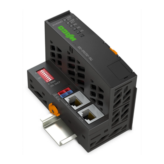
Page 47: View
View Pos : 25.1 /Serie 750 (WAGO-I/O-SYST EM)/Ger ätebesc hrei bung (alte Str uktur)/Ansic ht/F el dbus koppl er/-contr oller/Leg ende/Ansic ht - allg. Einl eitung für ETHERN ET-EC O-Koppler (352) @ 7\mod_1266336138443_21.doc x @ 50863 @ @ 1 The view below shows the different parts of the device: •... -
Page 48: Table 11: Legend For Figure "View
>"Voltage Supply" Pos : 25.8 /Serie 750 (WAGO-I/O-SYST EM)/Ger ätebesc hrei bung (alte Str uktur)/Ansic ht/F el dbus koppl er/-contr oller/Leg ende/Ansic ht - Legende für Verrieg elungssc hei be Nr: 9 @ 7\mod_1266417354526_21.doc x @ 50966 @ @ 1 „Mounting“... -
Page 49: Connectors
Pos : 28 /Serie 750 ( WAGO-I/O-SYST EM)/Ger ätebesc hrei bung (alte Str uktur)/Sc hematische Sc hal tbilder/F eldbus koppler /-controll er/Geräteeinspeis ung - Ü berschrift 3 und Einl eitung 750-0xxx @ 5\mod_1245074097866_21.doc x @ 35349 @ 3 @ 1... -
Page 50: Fieldbus Connection
Pos : 31.5 /Serie 750 (WAGO-I/O-SYST EM)/Ger ätebesc hrei bung (alte Str uktur)/Ansc hlüs se/Fel dbus koppl er/-contr oller/T abell e, Abbildung, Busansc hlus s und Stec kerbelegung RJ- 45- Stec ker @ 5\mod_1245073518124_21.doc x @ 35342 @ @ 1... -
Page 51: Display Elements
Figure 27: Display Elements Pos : 34.3 /Serie 750 (WAGO-I/O-SYST EM)/Ger ätebesc hrei bung (alte Str uktur)/Anz eigeel emente/F el dbus koppl er/-contr oller/Leg ende/Anz eigeelemente - Ei nleitung und Tabellenüberschrift F eldbusstatus (EC O) @ 7\mod_1266502041215_21.doc x @ 51064 @ @ 1 For the diagnostics of the different ranges fieldbus and node, the LED’s can be... -
Page 52: Operating Elements
Pos : 37.1 /Serie 750 (WAGO-I/O-SYST EM)/Ger ätebesc hrei bung (alte Str uktur)/Bedi enel emente/F eldbus koppler/-c ontroll er/Ser vic e-Sc hni ttstelle - Übersc hrift 3, und allgemei ne Ei nleitung @ 4\mod_1239105167430_21.doc... -
Page 53: Address Selection Switch
Pos : 39.2 /Serie 750 (WAGO-I/O-SYST EM)/Ger ätebesc hrei bung (alte Str uktur)/Bedi enel emente/F eldbus koppler/-c ontroll er/DIP-Sc halter-Bil d ( 8 ... 1 von oben nac h unten) Bilduntersc hrift: Adres s wahlsc hal ter @ 4\mod_1239180034696_21.doc... -
Page 54: Technical Data
Pos : 41 /All e Seri en (Allgemei ne Module)/Ü berschriften/Ebene 2/Tec hnische D aten - Ü bersc hrift 2 @ 3\mod_1232967587687_21.doc x @ 26924 @ 2 @ 1 Technical Data Pos : 42.1 /Serie 750 (WAGO-I/O-SYST EM)/Ger ätebesc hrei bung (alte Str uktur)/Technisc he Daten/VS (Variabl ensteuerung)/Technisc he Daten Ger ät ( VS) - XTR @ 15\mod_1369311215011_21.doc x @ 120260 @ 3 @ 1 4.5.1 Device Data Table 16: Technical Data –... -
Page 55: Supply
WAGO-I/O-SYSTEM 750 XTR Device Description 750-352/040-000 FC ETHERNET G3 XTR 4.5.3 Supply Table 4: Technical Data – Supply ® Power supply via CAGE CLAMP 24 VDC (power supply via SELV/PELV connectors power supply unit) under laboratory conditions +15 °C … +35 °C 18 V …... -
Page 56: Accessories
Follow the installation instructions Pos : 42.5 /Serie 750 (WAGO-I/O-SYST EM)/Ger ätebesc hrei bung (alte Str uktur)/Technisc he Daten/VS (Variabl ensteuerung)/Technisc he Daten kli matisc he U mwel tbedi ngungen (VS) - XTR @ 15\mod_1369387559187_21.doc x @ 120360 @ 3 @ 1 4.5.8... -
Page 57: Approvals
Pos : 45.6 /Dokumentation allgemei n/Glieder ungs elemente/---Leerabs atz-(2Z)--- @ 3\mod_1224662755687_0.doc x @ 24460 @ @ 1 Pos : 45.7 /Serie 750 (WAGO-I/O-SYST EM)/Ger ätebesc hrei bung (alte Str uktur)/Zul ass ung en/Ex/Zul ass ungen FBkoppl er/-c ontroller 750- xxxx Ex, ohne Vari antenang abe - Einl eitung @ 9\mod_1285063104018_21.doc x @ 64892 @ @ 1... -
Page 58: Standards And Guidelines
“nC” level of protection Pos : 48.3 /Serie 750 (WAGO-I/O-SYST EM)/Ger ätebesc hrei bung (alte Str uktur)/Nor men und Richtlini en/Nor men und Richtlini en XTR - Mec hani k und Kli ma Komponenten-HB 2017 @ 30\mod_1505808045352_21.doc x @ 461389 @ @ 1 Manual Version 1.3.0... -
Page 59: Table 24: Climatic And Mechanical Environmental Conditions And
WAGO-I/O-SYSTEM 750 XTR Device Description 750-352/040-000 FC ETHERNET G3 XTR Table 24: Climatic and Mechanical Environmental Conditions and Shipbuilding Standard Test Value Transport EN 60870-2-2 Ct2(2k4) (except precipitation/water/moisture) Mechanical Environmental Conditions EN 61850-3 Achieved EN 60870-2-2 EN 60721-3-1 EN 60721-3-3... -
Page 60: Table 25: Emc - Immunity To Interference
Pos : 48.5 /Serie 750 (WAGO-I/O-SYST EM)/Ger ätebesc hrei bung (alte Str uktur)/Nor men und Richtlini en/EM V-Nor men F Bkoppl er/-contr oller 750- xxxx/0040- 0000, ohne Vari antenangabe - Einlei tung XTR @ 18\mod_1395916932582_21.doc... - Page 61 The list of ship certifications issued is available in the section “Approvals”. Pos : 48.7 /Serie 750 (WAGO-I/O-SYST EM)/Ger ätebesc hrei bung (alte Str uktur)/Nor men und Richtlini en/Nor men Störauss endung XTR @ 18\mod_1394087664442_21.doc x @ 147358 @ @ 1 Manual Version 1.3.0...
-
Page 62: Table 26: Emc - Emission Of Interference
Device Description WAGO-I/O-SYSTEM 750 XTR 750-352/040-000 FC ETHERNET G3 XTR Table 26: EMC – Emission of Interference Standard Test Value Enclosure Emission of Interference • EN 61000-6-3 30 dB(µV/m), QP, 30 MHz … 230 MHz • EN 55032 Class B 37 dB(µV/m), QP, 230 MHz …... -
Page 63: Table 27: Emc - Emission Of Interference - Telecommunication
EMC 2). Pos : 48.9 /Serie 750 (WAGO-I/O-SYST EM)/Ger ätebesc hrei bung (alte Str uktur)/Nor men und Richtlini en/Nor men und Ei ns atz beding ung en für Bahnanwendungen (EN 50155) XTR @ 28\mod_1486482984774_21.doc x @ 405384 @ @ 1 Manual Version 1.3.0... -
Page 64: Table 28: Standards And Rated Conditions For Rail Applications
9.11 Materials (Fire Protection) EN 45545-2 Hazard level HL3 WAGO is a company certified in accordance with the IRIS quality standard. Pos : 49 /D okumentation allgemei n/Glieder ungs elemente/---Seitenwechs el--- @ 3\mod_1221108045078_0.doc x @ 21810 @ @ 1 Manual... -
Page 65: Mounting
Pos : 50 /All e Seri en (Allgemei ne Module)/Ü berschriften/Ebene 1/M onti eren - Ü bersc hrift 1 @ 3\mod_1225446744750_21.doc x @ 24900 @ 1 @ 1 Mounting Pos : 51.1 /Serie 750 (WAGO-I/O-SYST EM)/M ontieren/D emontieren/Einbaul age XTR @ 16\mod_1373976754254_21.doc x @ 126292 @ 2 @ 1 Installation Position... -
Page 66: Figure 30: Mounting Positions
End stop for DIN 35 rail, 10 mm wide WAGO item no. 249-197 End stop for DIN 35 rail, 14 mm wide Pos : 51.2 /Serie 750 (WAGO-I/O-SYST EM)/M ontieren/D emontieren/I/O-Modul e 750xxxx/0040xxxx 4g-5g @ 15\mod_1367558844291_21.doc x @ 118470 @ @ 1 Manual Version 1.3.0... -
Page 67: Overall Configuration
• Use the reinforced end stop 249-197. Pos : 51.3 /Serie 750 (WAGO-I/O-SYST EM)/M ontieren/D emontieren/Gesamtaus bau XTR @ 16\mod_1373976975062_21.doc x @ 126295 @ 2 @ 1 Overall Configuration The maximum total length of a fieldbus node without fieldbus coupler/controller is 780 mm including end module. -
Page 68: Mounting Onto Carrier Rail
Mounting WAGO-I/O-SYSTEM 750 XTR 750-352/040-000 FC ETHERNET G3 XTR Pos : 51.5 /Serie 750 (WAGO-I/O-SYST EM)/M ontieren/D emontieren/M ontage auf Tr agschi ene @ 3\mod_1225447227234_21.doc x @ 24906 @ 233 @ 1 Mounting onto Carrier Rail 5.3.1 Carrier Rail Properties All system components can be snapped directly onto a carrier rail in accordance with the European standard EN 60175 (DIN 35). -
Page 69: Wago Din Rails
35 × 15; 2.3 mm; copper; unslotted 210-196 35 × 8.2; 1.6 mm; aluminum; unslotted Pos : 51.6 /Serie 750 (WAGO-I/O-SYST EM)/M ontieren/D emontieren/Abstände @ 3\mod_1225448283750_21.doc x @ 24920 @ 2 @ 1 Spacing The spacing between adjacent components, cable conduits, casing and frame sides must be maintained for the complete fieldbus node. -
Page 70: Mounting Sequence
Pos : 51.11 /Serie 750 ( WAGO-I/O-SYST EM)/Wichtig e Erl äuter ung en (alte Struktur)/Sic her heits- und s onstige Hi nweis e/Hi nweis/Hinweis: Bus abschl uss XTR nic ht verges sen! @ 15\mod_1368426836647_21.doc x @ 119458 @ @ 1... -
Page 71: Inserting And Removing Devices
Switch off all power to the device prior to performing any installation, repair or maintenance work. Pos : 51.16 /Serie 750 ( WAGO-I/O-SYST EM)/Monti eren/D emonti eren/F eldbus koppler/C ontroll er ei nfügen @ 3\mod_1234168173031_21.doc x @ 27456 @ 3 @ 1 5.6.1... -
Page 72: Removing The Fieldbus Coupler/Controller
Electrical connections for data or power contacts to adjacent I/O modules are disconnected when removing the fieldbus coupler/controller. Pos : 51.19 /Serie 750 ( WAGO-I/O-SYST EM)/Monti eren/D emonti eren/XTR-I/O-Modul ei nfüg en @ 28\mod_1486551092321_21.doc x @ 405487 @ 3 @ 1 5.6.3... -
Page 73: Removing The I/O Module
(if any) to the fieldbus coupler/controller or to the previous or possibly subsequent I/O module are established. Pos : 51.20 /Serie 750 ( WAGO-I/O-SYST EM)/Monti eren/D emonti eren/XTR-I/O-Modul entfernen @ 28\mod_1486551166032_21.doc x @ 405491 @ 3 @ 1 5.6.4 Removing the I/O Module Remove the I/O module from the assembly by pulling the release tab. -
Page 74: Connect Devices
Data Contacts/Local Bus Pos : 54.2 /Serie 750 (WAGO-I/O-SYST EM)/Ger ätebesc hrei bung (alte Str uktur)/Ansc hlüs se/Datenkontakte - Fel dbus koppl er/-c ontroller und Modul e – Abbildung und Besc hrei bung @ 3\mod_1231771259187_21.doc x @ 26002 @ @ 1 Communication between the fieldbus coupler/controller and the I/O modules as well as the system supply of the I/O modules is carried out via the local bus. -
Page 75: Power Contacts/Field Supply
Power Contacts/Field Supply Pos : 54.7 /Serie 750 (WAGO-I/O-SYST EM)/Wic htige Erläuterungen (al te Str uktur)/Sic herheits- und s onstige Hinweise/Vorsic ht/Vorsic ht: Verletz ungsgefahr durc h sc harfkantige M esser kontakte! @ 6\mod_1256193279401_21.doc x @ 43414 @ @ 1 Risk of injury due to sharp-edged blade contacts! The blade contacts are sharp-edged. -
Page 76: Connecting A Conductor To The Cage Clamp
WAGO-I/O-SYSTEM 750 XTR 750-352/040-000 FC ETHERNET G3 XTR Pos : 54.10 /Serie 750 ( WAGO-I/O-SYST EM)/Ansc hließ en/Leiter an CAGE CLAMP ansc hließ en (allgemein) - Ü berschrift 2 und T ext @ 3\mod_1225448660171_21.doc x @ 24928 @ 2 @ 1 ®... -
Page 77: Function Description
Figure 39: Operating System Pos : 58.2 /Serie 750 (WAGO-I/O-SYST EM)/Ger ätebesc hrei bung (alte Str uktur)/Anz eigeel emente/F el dbus koppl er/-contr oller/Leg ende/Informati on: Infor mationen zu der LED-Sig nalisi erung @ 4\mod_1239098329547_21.doc x @ 30154 @ @ 1... -
Page 78: Process Data Architecture
Observe the number of input and output bits or bytes for the individual I/O modules. Pos : 61.4 /Serie 750 (WAGO-I/O-SYST EM)/F unktions beschr eibung/Prozes sabbild/Infor mation: Infor mati onen z u dem fel dbuss pezifisc hen Prozes sabbil d @ 4\mod_1239027644580_21.doc x @ 30018 @ @ 1 Manual... -
Page 79: Process Data Ethernet/Ip
Pos : null /Serie 750 (WAGO-I/O-SYST EM)/Funktions bes chr eibung/Proz ess abbil d/Pr oz ess abbild wortweis e aufgebaut ( mit wor d-alignment) (750- 841) (MOD BUS und EtherN et/IP) @ 6\mod_1256032355828_21.doc x @ 43119 @ @ 1 For the fieldbus controller with MODBUS and EtherNet/IP, the process image is built up word-by-word (with word alignment). -
Page 80: Data Exchange
Pos : 64.2 /Serie 750 (WAGO-I/O-SYST EM)/F unktions beschr eibung/Datenaus tausc h/D atenaustaus ch - Ei n F eldbus koppler kann ei ne bes timmte Anz ahl glei chz eitiger Verbindung en (Koppler) @ 7\mod_1265975390320_21.doc... -
Page 81: Addressing
Pos : 64.8 /Serie 750 (WAGO-I/O-SYST EM)/F unktions beschr eibung/Datenaus tausc h/Speic her ber eiche M ODBU S/Speic her ber eiche M ODBU S - Spi egel n der Ausgangsdaten @ 6\mod_1256047661921_21.doc x @ 43254 @ @ 1 In addition, all output data is mirrored in the FC ETHERNET G3 XTR to a memory area with the address offset 0x0200 and 0x1000. -
Page 82: Data Exchange Between Modbus/Tcp Master And I/O Modules
I/O modules for angle and distance measurement Pos : 64.12 /Serie 750 ( WAGO-I/O-SYST EM)/Funkti onsbesc hrei bung/D atenaustausch/Datenaus tausc h - D atenaustausc h MOD BUS/TCP-M aster und I/O-M odule @ 6\mod_1256049861734_21.doc x @ 43310 @ 3 @ 1 7.3.2... -
Page 83: Figure 41: Data Exchange Between Modbus Master And I/O Modules
WAGO-I/O-SYSTEM 750 XTR Function Description 750-352/040-000 FC ETHERNET G3 XTR Access by word to the digital I/O modules is carried out in accordance with the following table: Table 31: Allocation of Digital Inputs and Outputs to Process Data Words in Accordance with the... -
Page 84: Data Exchange Between Ethernet/Ip Master And I/O Modules
WAGO-I/O-SYSTEM 750 XTR 750-352/040-000 FC ETHERNET G3 XTR Pos : 64.13 /Serie 750 ( WAGO-I/O-SYST EM)/Funkti onsbesc hrei bung/D atenaustausch/Datenaus tausc h - D atenaustausc h EtherNet/IP-Mas ter und I/O-Modul e @ 6\mod_1256050145625_21.doc x @ 43322 @ 3 @ 1 7.3.3... -
Page 85: Commissioning
Pos : 67.2 /Serie 750 (WAGO-I/O-SYST EM)/In Betrieb nehmen/Fel dbus knoten i n Betrieb nehmen/Einl eitung - Hi nweis: Exempl arisches Beispi el, 2 erfor derliche Ar bei tssc hritte (Koppl er/Contr oller) @ 7\mod_1275300634223_21.doc... -
Page 86: Connecting Client Pc And Fieldbus Nodes
Pos : 67.17.1 /Serie 750 ( WAGO-I/O- SYST EM)/In Betri eb nehmen/F eldbus knoten in Betri eb nehmen/IP-Adres se mi t dem Adress wahlsc halter vergeben - Ü bers chrift 3 @ 5\mod_1243949279644_21.doc x @ 34680 @ 3 @ 1... - Page 87 Management System”. Pos : 67.17.3 /Serie 750 ( WAGO-I/O- SYST EM)/In Betri eb nehmen/F eldbus knoten in Betri eb nehmen/IP-Adres se mi t dem Adress wahlsc halter vergeben - Sc hritte 1- 3 @ 5\mod_1243949663207_21.doc x @ 34687 @ @ 1...
-
Page 88: Assigning Ip Address Via Dhcp
DHCP server on the network. Pos : 67.18.2 /Serie 750 ( WAGO-I/O- SYST EM)/In Betri eb nehmen/F eldbus knoten in Betri eb nehmen/IP-Adres se mi t DHC P vergeben T eil 2 @ 9\mod_1282136848186_21.doc x @ 63897 @ 4 @ 1... -
Page 89: Enable Dhcp
Pos : 67.18.6 /Serie 750 ( WAGO-I/O- SYST EM)/In Betri eb nehmen/F eldbus knoten in Betri eb nehmen/Hinweis: Weitere Informati onen z um Ausles en der IP-Adresse mittels „ WAGO Ethernet Setti ngs“ @ 5\mod_1244637843934_21.doc... - Page 90 Pos : 67.18.13 /Seri e 750 ( WAGO-I/O-SYSTEM)/In Betrieb nehmen/Fel dbus knoten in Betrieb nehmen/Untergruppen/Wähl en Si e di e Option " us e IP fr om EEPROM" -DHC P deakti vi eren @ 22\mod_1430986790258_21.doc...
-
Page 91: Assigning Ip Address Via "Wago Ethernet Settings
Pos : 67.20.5 /Serie 750 ( WAGO-I/O- SYST EM)/In Betri eb nehmen/F eldbus knoten in Betri eb nehmen/Z ur Datenkommuni kation können Kommuni kati ons kabel oder WAGO-F unkadapter ver wendet werden. @ 5\mod_1243599181347_21.doc x @ 34623 @ @ 1... -
Page 92: Assigning The Ip Address Via Bootp
Pos : 67.20.12 /Seri e 750 ( WAGO-I/O-SYSTEM)/In Betrieb nehmen/Fel dbus knoten in Betrieb nehmen/IP- Adr ess e mit "WAGO Ether net Settings" vergeben, Schritt 9 bis 10 IP über nehmen, WBM öffnen @ 5\mod_1244199645897_21.doc... -
Page 93: Note Mac Id
Pos : 67.22.10 /Seri e 750 ( WAGO-I/O-SYSTEM)/In Betrieb nehmen/Fel dbus knoten in Betrieb nehmen/Starten Si e den PC, der die F unkti on des M asters und BootP- Ser vers überni mmt. @ 4\mod_1239087816984_21.doc... -
Page 94: Determining Ip Addresses
750-352/040-000 FC ETHERNET G3 XTR Pos : 67.22.16 /Seri e 750 ( WAGO-I/O-SYSTEM)/In Betrieb nehmen/Fel dbus knoten in Betrieb nehmen/IP- Adr ess e ermi tteln ( BootP) Ü bersc hrift 4 @ 6\mod_1264497894131_21.doc x @ 48701 @ 4 @ 1 8.2.4.2... -
Page 95: Assigning The Ip Address Permanently By Option "Use Ip From Eeprom
Pos : 67.22.22 /Seri e 750 ( WAGO-I/O-SYSTEM)/In Betrieb nehmen/Fel dbus knoten in Betrieb nehmen/Das U msc halten auf die Option nehmen Si e i m Web- Bas ed-Manag. (-352, -881, -882) @ 9\mod_1292516140287_21.doc x @ 67573 @ @ 1... - Page 96 Pos : 67.22.27 /Seri e 750 ( WAGO-I/O-SYSTEM)/In Betrieb nehmen/Fel dbus knoten in Betrieb nehmen/Untergruppen/Wähl en Si e di e Option " us e IP fr om EEPROM" - BootP deakti vieren @ 22\mod_1430745863672_21.doc x @ 181688 @ @ 1...
-
Page 97: Reasons For Failed Ip Address Assignment
750-352/040-000 FC ETHERNET G3 XTR Pos : 67.22.30 /Seri e 750 ( WAGO-I/O-SYSTEM)/In Betrieb nehmen/Fel dbus knoten in Betrieb nehmen/Gründe für ei ne fehlg esc hlagene IP-Adress vergabe (bei BootP) (Koppl er) @ 6\mod_1264505260541_21.doc x @ 48755 @ 4 @ 1 8.2.4.4... -
Page 98: Testing The Function Of The Fieldbus Node
Pos : 67.24.4 /Serie 750 ( WAGO-I/O- SYST EM)/In Betri eb nehmen/F eldbus knoten in Betri eb nehmen/H ochl auf und LEDs - F ehler allgemei n, Hi nweis: Signalisierung/Bli nkc ode-Aus w. @ 4\mod_1243594306433_21.doc... -
Page 99: Preparing The Flash File System
Pos : 67.26.3 /Serie 750 ( WAGO-I/O- SYST EM)/In Betri eb nehmen/F eldbus knoten in Betri eb nehmen/Hinweis: Kommuni kati ons kabel 750-920 nic ht unter Spannung s tec ken! (Koppler/C ontroll er) @ 4\mod_1239172916562_21.doc... - Page 100 100 Commissioning WAGO-I/O-SYSTEM 750 XTR 750-352/040-000 FC ETHERNET G3 XTR In the top menu bar, select [Reset File System] to format the file system and to extract the WBM pages of the flash file system. Formatting and extracting is complete when the status window displays "Resetting the file system successfully".
-
Page 101: Setting Date And Time
Synchronize the system time using “WAGO Ethernet Settings” Pos : null /Serie 750 (WAGO-I/O-SYST EM)/Web-Bas ed-M anagement-Sys tem WBM /Seite Cloc k/Hi nweis : U hrzeit nic ht während ei ner WAGO I/O-CH ECK Kommuni kati on ei nstellen! @ 33\mod_1543847260289_21.doc x @ 512059 @ @ 1... - Page 102 Saving Time (DST). Pos : null /Serie 750 (WAGO-I/O-SYST EM)/In Betrieb nehmen/F eldbus knoten i n Betri eb nehmen/IP-Adresse über das Web-based M anagement-System vergeben - Sc hritte 6-7 SUBM IT, N eustart @ 5\mod_1244125431662_21.doc x @ 34964 @ @ 1 Click on [SUBMIT] to apply the changes in your fieldbus node.
-
Page 103: Restoring Factory Settings
Pos : 67.30.4 /Serie 750 ( WAGO-I/O- SYST EM)/In Betri eb nehmen/F eldbus knoten in Betri eb nehmen/Wer ksei nstellungen wi ederherstellen - " Eth Settings"starten,Default,C onti nue, N eust Sc hritte 4-5 @ 5\mod_1244645750981_21.doc... -
Page 104: Configuring Via The Web-Based Management System (Wbm)
104 Configuring via the Web-Based Management System (WBM)WAGO-I/O-SYSTEM 750 XTR 750-352/040-000 FC ETHERNET G3 XTR Pos : 69.1 /Serie 750 (WAGO-I/O-SYST EM)/Web-Bas ed-Management-System WBM/Im Web-Based-Management- System konfigurier en (Ei nleitung und Übersc hrift 1) @ 4\mod_1242217768500_21.doc x @ 33098 @ 1 @ 1 Configuring via the Web-Based Management... - Page 105 Pos : 69.2.11 /Serie 750 ( WAGO-I/O- SYST EM)/Web-Bas ed-M anagement-Sys tem WBM/Ü bersicht N avigati onsliste/Features @ 16\mod_1374065780481_0.doc x @ 126475 @ @ 1 • Features Pos : 69.2.12 /Serie 750 ( WAGO-I/O- SYST EM)/Web-Bas ed-M anagement-Sys tem WBM/Ü bersicht N avigati onsliste/I/O c onfig @ 16\mod_1374066198093_0.doc x @ 126511 @ @ 1 • I/O config Pos : 69.2.13 /Serie 750 ( WAGO-I/O- SYST EM)/Web-Bas ed-M anagement-Sys tem WBM/Ü...
-
Page 106: Information
The WBM page “Information” contains an overview of all important information about your fieldbus coupler/controller. Pos : 69.5 /Serie 750 (WAGO-I/O-SYST EM)/Web-Bas ed-Management-System WBM/Seite Infor mation/Infor mation - Bild ( 750- 352) @ 8\mod_1278927483716_21.doc x @ 59602 @ @ 1 Figure 43: WBM page “Information” (example) Pos : 69.6 /Dokumentation allgemei n/Glieder ungs elemente/---Seitenwechs el--- @ 3\mod_1221108045078_0.doc x @ 21810 @ @ 1... -
Page 107: Table 33: Wbm Page "Information
Pos : 69.8 /Serie 750 (WAGO-I/O-SYST EM)/Web-Bas ed-Management-System WBM/Seite Infor mation/Infor mation - T abell e (750-352, -829, - 831, -849, - 852, - 871,- 880 ,- 884, 889) T eil 2 @ 8\mod_1279001989967_21.doc x @ 59694 @ @ 1... -
Page 108: Ethernet
Ethernet. Pos : 69.11 /Serie 750 ( WAGO-I/O-SYST EM)/Web-Bas ed-M anagement-Sys tem WBM/Seite ETH ERN ET/Ether net - Bild ( 750-352, - 831, - 852, -880, -881, - 884, -889..) @ 12\mod_1342085448431_21.doc x @ 99773 @ @ 1 Manual Version 1.3.0... -
Page 109: Figure 44: Wbm Page "Ethernet
WAGO-I/O-SYSTEM 750 XTRConfiguring via the Web-Based Management System (WBM)109 750-352/040-000 FC ETHERNET G3 XTR Figure 44: WBM page “Ethernet” Pos : 69.12 /D okumentati on allgemei n/Gli ederungsel emente/---Seitenwec hs el--- @ 3\mod_1221108045078_0.doc x @ 21810 @ @ 1 Manual... -
Page 110: Table 34: Wbm Page "Ethernet
Pos : 69.17 /Serie 750 ( WAGO-I/O-SYST EM)/Web-Bas ed-M anagement-Sys tem WBM/Seite ETH ERN ET/Ether net - T abelle 1.2.1 Fas t-Aging als Z eile ( 352, 829, 831, 881, 880, 884) @ 13\mod_1349863424882_21.doc x @ 104200 @ @ 1... - Page 111 Pos : 69.19 /Serie 750 ( WAGO-I/O-SYST EM)/Web-Bas ed-M anagement-Sys tem WBM/Seite ETH ERN ET/Ether net - T abelle Teil 2 ( Port Mirror, Sniffer Port, Mirror Port) (352, 829, 880, 881, 884) @ 8\mod_1280405722425_21.doc...
-
Page 112: Tcp/Ip
WBM page. Pos : 69.25 /Serie 750 ( WAGO-I/O-SYST EM)/Web-Bas ed-M anagement-Sys tem WBM/Seite TCP/IP/Hinweis: DIP-Sc hal ter auf „ 0“ und „use IP from EEPR OM“ akti v s chalten! @ 8\mod_1277115631129_21.doc x @ 58203 @ @ 1 Set the DIP switch to “0” and enable “use IP from EEPROM”! Before you change parameters on this page, set the DIP switch to zero and on the “Port”... -
Page 113: Table 35: Wbm Page "Tcp/Ip
Pos : 69.28 /Serie 750 ( WAGO-I/O-SYST EM)/Web-Bas ed-M anagement-Sys tem WBM/Seite TCP/IP/TC P/IP - T abell e, Z eile Switc h-IP-Adress e ( 750- 352, - 880, -881, 884, 852, 831) @ 7\mod_1275317154555_21.doc x @ 57249 @ @ 1... -
Page 114: Port
114 Configuring via the Web-Based Management System (WBM)WAGO-I/O-SYSTEM 750 XTR 750-352/040-000 FC ETHERNET G3 XTR Pos : 69.31 /Serie 750 ( WAGO-I/O-SYST EM)/Web-Bas ed-M anagement-Sys tem WBM/Seite Port/Port - Einl eitung @ 4\mod_1242385203187_21.doc x @ 33225 @ 2 @ 1 Port Use the “Port”... -
Page 115: Table 36: Wbm Page "Port
750-352/040-000 FC ETHERNET G3 XTR Pos : 69.34 /Serie 750 ( WAGO-I/O-SYST EM)/Web-Bas ed-M anagement-Sys tem WBM/Seite Port/Port - T abelle (750- 880, -881, -882 -352, - 873) T eil 1 "FT P" @ 8\mod_1279004143276_21.doc x @ 59698 @ @ 1 Table 36: WBM page “Port”... -
Page 116: Snmp
Pos : 69.41.3 /Serie 750 ( WAGO-I/O- SYST EM)/Web-Bas ed-M anagement-Sys tem WBM/Seite SNM P/SNMP - Das Pr otokoll wird i n der Versi on 1, 2c und 3 unterstützt. (Koppl er) @ 29\mod_1489591610964_21.doc x @ 413702 @ @ 1... -
Page 117: Snmp V1/V2C
Pos : 69.41.9 /Serie 750 ( WAGO-I/O- SYST EM)/Web-Bas ed-M anagement-Sys tem WBM/Seite SNM P/SNMP - In der Versi on 1 und 2c von SNM P handel t es sic h um einen Community-Nachric htenaustaus ch @ 4\mod_1243331840562_21.doc... -
Page 118: Snmp V3
Pos : 69.41.14 /Seri e 750 ( WAGO-I/O-SYSTEM)/Web- Based-Manag ement- System WBM/Seite SNMP/SNM P - In der Versi on 3 von SNMP ist der Nac hrichtenaus tausc h an Benutz er gebunden. ( Koppler) @ 29\mod_1489592821181_21.doc... -
Page 119: Watchdog
Click the link "Watchdog" to go to a WBM page where you can specify the settings for the connection and MODBUS watchdog. Pos : 69.44 /Serie 750 ( WAGO-I/O-SYST EM)/Web-Bas ed-M anagement-Sys tem WBM/Seite Watchdog/Watchdog - Bild (750- xxx) (352/831/41/9/52/71/3/80/1/2/4/5) @ 13\mod_1349182518669_21.doc x @ 103904 @ @ 1 Figure 47: WBM Page “Watchdog”... -
Page 120: Table 39: Wbm Page "Watchdog
120 Configuring via the Web-Based Management System (WBM)WAGO-I/O-SYSTEM 750 XTR 750-352/040-000 FC ETHERNET G3 XTR Table 39: WBM Page “Watchdog” Connection watchdog Entry Default Description Connection Timeout Value Monitoring period for TCP links. (100 ms) After the completion of this period without any subsequent data traffic, the TCP connection is closed. -
Page 121: Security
Max. 32 characters inclusive special characters. Pos : 69.48 /Serie 750 ( WAGO-I/O-SYST EM)/Web-Bas ed-M anagement-Sys tem WBM/Seite Sec urity/Hi nweis : N ach Softwar e-Res et Zugriff er neuer n! @ 6\mod_1260540394978_21.doc x @ 47059 @ @ 1 Renew access after software reset! -
Page 122: Figure 48: Wbm Page "Security
750-352/040-000 FC ETHERNET G3 XTR Figure 48: WBM page “Security” Pos : 69.50.1 /Serie 750 ( WAGO-I/O- SYST EM)/Web-Bas ed-M anagement-Sys tem WBM/Seite Sec urity/Security - Tabelle 1.1 Webser ver Sec urity @ 4\mod_1242632218843_21.doc x @ 33439 @ @ 1 Manual... -
Page 123: Table 40: Wbm Page "Security
Web interface Pos : 69.50.2 /Serie 750 ( WAGO-I/O- SYST EM)/Web-Bas ed-M anagement-Sys tem WBM/Seite Sec urity/Security - Tabelle 1.2 Webser ver and FT P Us er c onfiguration @ 20\mod_1411463793918_21.doc x @ 164172 @ @ 1 Webserver and FTP User configuration *... -
Page 124: Modbus
Pos : 69.53 /Serie 750 ( WAGO-I/O-SYST EM)/Web-Bas ed-M anagement-Sys tem WBM/Seite MOD BUS/MOD BUS - Bil d (750-352) @ 13\mod_1352801360205_21.doc x @ 106010 @ @ 1 Figure 49: WBM page “Modbus” Pos : 69.54 /Serie 750 ( WAGO-I/O-SYST EM)/Web-Bas ed-M anagement-Sys tem WBM/Seite MOD BUS/MOD BUS UDP Multic ast Address Setup - Tabelle ( Koppler) (352) @ 13\mod_1352816258349_21.doc x @ 106037 @ @ 1 Manual... -
Page 125: Table 41: Wbm Page "Modbus
Pos : 69.55 /Serie 750 ( WAGO-I/O-SYST EM)/Web-Bas ed-M anagement-Sys tem WBM/Seite MOD BUS/MOD BUS Configur ati on R egisters - T abelle (352, 829, 880, 881, 882, 831, 852, 884, 885, 889) @ 14\mod_1358171402526_21.doc... -
Page 126: Features
Use the “Features” WBM page to enable or disable additional functions. Pos : 69.59 /Serie 750 ( WAGO-I/O-SYST EM)/Web-Bas ed-M anagement-Sys tem WBM/Seite F eatur es/F eatur es - Bild (750- 829, 831, 880, 881, 882, 885, 852, 352) @ 8\mod_1276864252513_21.doc x @ 58171 @ @ 1 Figure 50: WBM Page “Features”... -
Page 127: I/O Config
WAGO-I/O-SYSTEM 750 XTRConfiguring via the Web-Based Management System (WBM)127 750-352/040-000 FC ETHERNET G3 XTR Pos : 69.62 /Serie 750 ( WAGO-I/O-SYST EM)/Web-Bas ed-M anagement-Sys tem WBM/Seite I/O C onfig/I/O C onfig - Ei nleitung (Koppler) (750-330, -352) @ 10\mod_1313403923757_21.doc x @ 76948 @ 2 @ 1 9.10 I/O Config Click the link “I/O config”... -
Page 128: Diagnostics
(see following figure). Pos : 73.2 /Serie 750 (WAGO-I/O-SYST EM)/Ger ätebesc hrei bung (alte Str uktur)/Anz eigeel emente/F el dbus koppl er/-contr oller/Bilder/Anz eigeel emente 750- 0352/0040- 0000 - Bild @ 18\mod_1392199297483_21.doc x @ 145262 @ @ 1 Figure 52: Display Elements Pos : 73.3 /Serie 750 (WAGO-I/O-SYST EM)/Di agnose/Fel dbus koppl er/-contr oller/LED- Signalisierung - T abellenkopf, LED-Zuordnung für die Di agnos e (all e Koppl er/C ontroller) @ 6\mod_1256652265984_21.doc x @ 43750 @ @ 1... -
Page 129: Evaluating Fieldbus Status
Pos : 73.7.2 /Serie 750 (WAGO-I/O-SYST EM)/Diag nose/Fel dbus koppl er/-contr oller/F eldbusstatus aus wer ten ('LIN K ACT 1, 2', 'M S', 'NS') mit EtherN et/IP - MS und NS für EtherNet/IP @ 9\mod_1282558697263_21.doc... -
Page 130: Evaluating Node Status - I/O Led (Blink Code Table)
The fieldbus node is operating correctly. Normal operation. Pos : 73.8.2 /Serie 750 (WAGO-I/O-SYST EM)/Diag nose/Fel dbus koppl er/-contr oller/Knotenstatus aus werten 2 - I/O-LED ( alle Koppler/C ontroll er) @ 18\mod_1390381556408_21.doc x @ 142694 @ @ 1 Start of the firmware. -
Page 131: Figure 53: Node Status - I/O Led Signaling
WAGO-I/O-SYSTEM 750 XTR Diagnostics 131 750-352/040-000 FC ETHERNET G3 XTR Figure 53: Node Status – I/O LED Signaling Figure 54: Error Message Coding Example of a module error: • The I/O LED starts the error display with the first flashing sequence (approx. -
Page 132: Table 47: Blink Code Table For The 'I/O' Led Signaling, Error Code 1
Pos : 73.9 /Serie 750 (WAGO-I/O-SYST EM)/Di agnose/Fel dbus koppl er/-contr oller/Blinkc ode-T abellen - Fehlerc ode 1...1.9 (750-0351, -0352) @ 8\mod_1280147436255_21.doc x @ 61242 @ @ 1 Table 47: Blink Code Table for the 'I/O' LED Signaling, Error Code 1 Error code 1: “Hardware and configuration error”... -
Page 133: Table 48: Blink Code Table For The 'I/O' Led Signaling, Error Code 2
Pos : 73.10 /Serie 750 ( WAGO-I/O-SYST EM)/Diagnos e/F eldbus koppler/-c ontroll er/Bli nkc ode-Tabellen - F ehl erc ode 1 - 10...13 nicht genutzt (750- 352, 362, 852, 862) @ 8\mod_1280148304533_21.doc x @ 61301 @ @ 1 10 ... 13 not used Pos : 73.11 /Serie 750 ( WAGO-I/O-SYST EM)/Diagnos e/F eldbus koppler/-c ontroll er/Bli nkc ode-Tabellen - F ehl erc ode 1.14...5 ( 750-0352/040- 000) XTR @ 18\mod_1392138063428_21.doc x @ 145134 @ @ 1... -
Page 134: Table 49: Blink Code Table For The 'I/O' Led Signaling, Error Code 3
134 Diagnostics WAGO-I/O-SYSTEM 750 XTR 750-352/040-000 FC ETHERNET G3 XTR Table 49: Blink Code Table for the 'I/O' LED Signaling, Error Code 3 Error code 3: "Protocol error, internal bus" Error Error Description Solution Argument --- Are passive power supply modules (750-613/040-000) -
Page 135: Table 50: Blink Code Table For The 'I/O' Led Signaling, Error Code 4
I/O modules without data are not counted (e.g., supply modules without diagnostics) Pos : 73.12 /Serie 750 ( WAGO-I/O-SYST EM)/Diagnos e/F eldbus koppler/-c ontroll er/Bli nkc ode-Tabellen - F ehl erc ode 6 ( 750-0352) @ 8\mod_1280140255621_21.doc x @ 61156 @ @ 1 Manual Version 1.3.0... -
Page 136: Table 52: Blink Code- Table For The I/O Led Signaling, Error Code 6
136 Diagnostics WAGO-I/O-SYSTEM 750 XTR 750-352/040-000 FC ETHERNET G3 XTR Table 52: Blink code- table for the I/O LED signaling, error code 6 Error code 6: "Fieldbus specific errors" Error Error description Solution Argument Turn off the power supply of the node. -
Page 137: Fault Behavior
750-352/040-000 FC ETHERNET G3 XTR Pos : 73.15 /Serie 750 ( WAGO-I/O-SYST EM)/Diagnos e/F eldbus koppler/-c ontroll er/F ehl er ver halten, F el dbus aus fall ( 750- 0341, -0352, -0330) @ 6\mod_1259588160031_21.doc x @ 46150 @ 23 @ 1 10.2... -
Page 138: Fieldbus Communication
These protocols are explained in more detail in the other sections. Pos : 76.2 /Serie 750 (WAGO-I/O-SYST EM)/F unktions beschr eibung/Fel dbus kommuni kati on/ETH ERNET /Implementierte Protokolle - Übersc hrift 2 (für ETHERN ET-Kurzbesc hrei bung) @ 4\mod_1236766863780_21.doc x @ 28180 @ 2 @ 1 11.1... -
Page 139: Table 54: Network Class A
WAGO-I/O-SYSTEM 750 XTR Fieldbus Communication 139 750-352/040-000 FC ETHERNET G3 XTR IP Addresses To allow communication over the network each fieldbus node requires a 32 bit Internet address (IP address). IP Address must be unique! For error free operation, the IP address must be unique within the network. -
Page 140: Table 57: Key Data Class A, B And C
192.000.000.XXX ... Approx. 2 Million 223.255.255.XXX Each WAGO ETHERNET fieldbus coupler or controller can be easily assigned an IP address via the implemented BootP protocol. For small internal networks we recommend selecting a network address from Class C. Do not set IP addresses to 0.0.0.0 or 255.255.255.255! Never set all bits to equal 0 or 1 in one byte (byte = 0 or 255). -
Page 141: Table 58: Example: Class B Address With Field For Subnet Ids
WAGO-I/O-SYSTEM 750 XTR Fieldbus Communication 141 750-352/040-000 FC ETHERNET G3 XTR Table 58: Example: Class B Address with Field for Subnet IDs Network ID Subnet ID Host ID Subnet Mask A subnet mask was introduced to encode the subnets in the Internet. This involves a bit mask, which is used to mask out or select specific bits of the IP address. - Page 142 142 Fieldbus Communication WAGO-I/O-SYSTEM 750 XTR 750-352/040-000 FC ETHERNET G3 XTR Specification of the network mask necessary! Specify the network mask defined by the administrator in the same way as the IP address when installing the network protocol. Gateway The subnets of the Internet are normally connected via gateways. The function of these gateways is to forward packets to other networks or subnets.
-
Page 143: Tcp (Transmission Control Protocol)
A complete list of “standardized services” is contained in the RFC 1700 (1994) specifications. Pos : 79 /Serie 750 ( WAGO-I/O-SYST EM)/F unktions beschr eibung/Fel dbus kommuni kati on/ETH ERNET /UDP (User D atagram Protoc ol) @ 4\mod_1237211297860_21.doc x @ 28505 @ 4 @ 1 11.1.1.3 UDP (User Datagram Protocol) The UDP protocol, like the TCP protocol, is responsible for the transport of data. -
Page 144: Configuration And Diagnostics Protocols
750-352/040-000 FC ETHERNET G3 XTR Pos : 81 /Serie 750 ( WAGO-I/O-SYST EM)/F unktions beschr eibung/Fel dbus kommuni kati on/ETH ERNET /Konfigurations- und Di agnos epr otokoll e - Ü bers chrift 3 @ 4\mod_1237211597686_21.doc x @ 28511 @ 3 @ 1 11.1.2... -
Page 145: Dhcp (Dynamic Host Configuration Protocol)
Pos : 85 /Serie 750 ( WAGO-I/O-SYST EM)/F unktions beschr eibung/Fel dbus kommuni kati on/ETH ERNET /DHCP (D ynamic H ost Configur ati on Pr otocol) ( 750-880, - 881, -882) @ 7\mod_1265297441531_21.doc x @ 49809 @ 4 @ 1... - Page 146 146 Fieldbus Communication WAGO-I/O-SYSTEM 750 XTR 750-352/040-000 FC ETHERNET G3 XTR The DHCP server then receives this message. The server contains a database in which the MAC ID and IP addresses are assigned to one another. When a MAC address is found a broadcast reply is transmitted via the network.
-
Page 147: Table 64: Meaning Of Dhcp Options
Pos : 86 /Serie 750 ( WAGO-I/O-SYST EM)/F unktions beschr eibung/Fel dbus kommuni kati on/ETH ERNET /DHCP (D ynamic H ost Configur ati on Pr otocol - Tabelle DHC P-Opti onen (750- 880, -881) @ 9\mod_1284377953925_21.doc... -
Page 148: Http (Hypertext Transfer Protocol)
Pos : 89.4 /Serie 750 (WAGO-I/O-SYST EM)/F unktions beschr eibung/Fel dbus kommuni kati on/ETH ERNET /Informati on: Weiter e i nformati on zu den i mpl ementi erten Pr otokoll en @ 7\mod_1265374349668_21.doc x @ 49929 @ @ 1 Manual Version 1.3.0... -
Page 149: Snmp (Simple Network Management Protocol)
Pos : 90.1 /Serie 750 (WAGO-I/O-SYST EM)/F unktions beschr eibung/Fel dbus kommuni kati on/SNM P (MIB)/SNM P (Si mple Networ k M anag ement Protokoll) - SNMP (Ü bers chrift 4) @ 7\mod_1270702804402_21.doc x @ 54939 @ 4 @ 1... -
Page 150: 11.1.2.6.1 Mib Ii Description
Pos : 90.6 /Serie 750 (WAGO-I/O-SYST EM)/F unktions beschr eibung/Fel dbus kommuni kati on/SNM P (MIB)/SNM P (Si mple Networ k M anag ement Protokoll) - Standar d-Traps (Ü bersc hrift 5) @ 7\mod_1270703854440_21.doc... -
Page 151: Application Protocols
750-352/040-000 FC ETHERNET G3 XTR Pos : 92 /Serie 750 ( WAGO-I/O-SYST EM)/F unktions beschr eibung/Fel dbus kommuni kati on/ETH ERNET /Anwendungs protokolle - Übersc hrift 3 und Einl eitungstext @ 4\mod_1237212360010_21.doc x @ 28535 @ 3 @ 1 11.1.3... -
Page 152: Modbus Functions
Modbus Function codes. Pos : 94.3 /Serie 750 (WAGO-I/O-SYST EM)/F unktions beschr eibung/Fel dbus kommuni kati on/MOD BUS/M ODBU S-Funktionen - Allgemeines - 15 Verbi ndungen ( x41) @ 4\mod_1235565560015_21.doc x @ 27682 @ @ 1 For the MODBUS protocol 15 connections are made available over TCP. Thus it... -
Page 153: Table 68: Basic Data Types Of Modbus Protocol
Registers Pos : 94.6 /Serie 750 (WAGO-I/O-SYST EM)/F unktions beschr eibung/Fel dbus kommuni kati on/MOD BUS/M ODBU S-Funktionen - Eing abe Adress e und Funkti onscode, Hi nweis @ 3\mod_1234955801125_21.doc x @ 27543 @ @ 1 To execute a desired function, specify the respective function code and the address of the selected input or output channel or of the register. -
Page 154: Use Of The Modbus Functions
Pos : 94.7 /Dokumentation allgemei n/Glieder ungs elemente/---Seitenwechs el--- @ 3\mod_1221108045078_0.doc x @ 21810 @ @ 1 Pos : 94.8 /Serie 750 (WAGO-I/O-SYST EM)/F unktions beschr eibung/Fel dbus kommuni kati on/MOD BUS/Anwendung der M ODBU S-Funkti onen - Einl eitung @ 7\mod_1265623985585_21.doc x @ 49940 @ 33 @ 1 11.2.2... -
Page 155: Description Of The Modbus Functions
The exception code contained in the exception has the following meaning: Pos : 94.9 /Serie 750 (WAGO-I/O-SYST EM)/F unktions beschr eibung/Fel dbus kommuni kati on/MOD BUS/Anwendung der M ODBU S-Funkti onen - T abelle "Excepti on-C odes" @ 7\mod_1265624178510_21.doc x @ 49943 @ @ 1... -
Page 156: Function Code Fc1 (Read Coils)
156 Fieldbus Communication WAGO-I/O-SYSTEM 750 XTR 750-352/040-000 FC ETHERNET G3 XTR Reading and writing of outputs via FC1 to FC4 is also possible by adding an offset! In the case of the read functions (FC1 ... FC4) the outputs can be additionally... -
Page 157: Function Code Fc2 (Read Discrete Inputs)
WAGO-I/O-SYSTEM 750 XTR Fieldbus Communication 157 750-352/040-000 FC ETHERNET G3 XTR lowest value. The assignment is thus made from 7 to 0 as follows: Table 73: Assignment of Inputs OFF OFF OFF ON OFF OFF ON OFF Coil Exception Table 74: Exception of Function Code FC1... -
Page 158: Table 76: Response Of Function Code Fc2
158 Fieldbus Communication WAGO-I/O-SYSTEM 750 XTR 750-352/040-000 FC ETHERNET G3 XTR Response The current value of the requested bits are packed into the data field. A binary 1 corresponds to the ON status and a 0 the OFF status. The lowest value bit of the first data byte contains the first bit of the inquiry. -
Page 159: Function Code Fc3 (Read Multiple Registers)
WAGO-I/O-SYSTEM 750 XTR Fieldbus Communication 159 750-352/040-000 FC ETHERNET G3 XTR 11.2.3.3 Function Code FC3 (Read Multiple Registers) This function reads the contents of holding registers from a slave device in word format. Request The request specifies the reference number (start register) and the word count (register quantity) of the registers to be read. -
Page 160: Function Code Fc4 (Read Input Registers)
160 Fieldbus Communication WAGO-I/O-SYSTEM 750 XTR 750-352/040-000 FC ETHERNET G3 XTR 11.2.3.4 Function Code FC4 (Read Input Registers) This function reads contents of input registers from the slave device in word format. Request The request specifies a reference number (start register) and the word count (register quantity) of the registers to be read. -
Page 161: Function Code Fc5 (Write Coil)
WAGO-I/O-SYSTEM 750 XTR Fieldbus Communication 161 750-352/040-000 FC ETHERNET G3 XTR 11.2.3.5 Function Code FC5 (Write Coil) This function writes a single output bit to the slave device. Request The request specifies the reference number (output address) of output bit to be written. -
Page 162: Function Code Fc6 (Write Single Register)
162 Fieldbus Communication WAGO-I/O-SYSTEM 750 XTR 750-352/040-000 FC ETHERNET G3 XTR 11.2.3.6 Function Code FC6 (Write Single Register) This function writes the value of one single output register to a slave device in word format. Request The request specifies the reference number (register address) of the first output word to be written. -
Page 163: Function Code Fc11 (Get Comm Event Counter)
750-352/040-000 FC ETHERNET G3 XTR Pos : 94.12 /Serie 750 ( WAGO-I/O-SYST EM)/Funkti onsbesc hrei bung/F eldbus kommuni kation/M ODBU S/Anwendung der MOD BUS-F unktionen - FC11, FC15, FC 16 @ 4\mod_1235567470328_21.doc x @ 27730 @ 444 @ 1 11.2.3.7 Function Code FC11 (Get Comm Event Counter) This function returns a status word and an event counter from the slave device’s... -
Page 164: Function Code Fc15 (Write Multiple Coils)
164 Fieldbus Communication WAGO-I/O-SYSTEM 750 XTR 750-352/040-000 FC ETHERNET G3 XTR 11.2.3.8 Function Code FC15 (Write Multiple Coils) This function sets a sequence of output bits to 1 or 0 in a slave device. The maximum number is 256 bits. -
Page 165: Function Code Fc16 (Write Multiple Registers)
WAGO-I/O-SYSTEM 750 XTR Fieldbus Communication 165 750-352/040-000 FC ETHERNET G3 XTR Exception Table 96: Exception of Function Code FC15 Byte Field name Example Byte 7 MODBUS function code 0x8F Byte 8 Exception code 0x01 or 0x02 11.2.3.9 Function Code FC16 (Write Multiple Registers) This function writes a sequence of registers in a slave device in word format. -
Page 166: Function Code Fc22 (Mask Write Register)
Pos : 94.13 /D okumentati on allgemei n/Gli ederungsel emente/---Seitenwec hs el--- @ 3\mod_1221108045078_0.doc x @ 21810 @ @ 1 Pos : 94.14 /Serie 750 ( WAGO-I/O-SYST EM)/Funkti onsbesc hrei bung/F eldbus kommuni kation/M ODBU S/Anwendung der MOD BUS-F unktionen ( x41) - FC 22 @ 4\mod_1235567699484_21.doc x @ 27737 @ 4 @ 1 11.2.3.10 Function Code FC22 (Mask Write Register) -
Page 167: Function Code Fc23 (Read/Write Multiple Registers)
750-352/040-000 FC ETHERNET G3 XTR Pos : 94.16 /Serie 750 ( WAGO-I/O-SYST EM)/Funkti onsbesc hrei bung/F eldbus kommuni kation/M ODBU S/Anwendung der MOD BUS-F unktionen - FC23 @ 4\mod_1235567802937_21.doc x @ 27740 @ 4 @ 1 11.2.3.11 Function Code FC23 (Read/Write Multiple Registers) This function performs a combination of a read and write operation in a single request. -
Page 168: Modbus Register Mapping
Pos : 94.20 /Serie 750 ( WAGO-I/O-SYST EM)/Funkti onsbesc hrei bung/F eldbus kommuni kation/M ODBU S/MOD BU S-Register-Mappi ng - Registerzugriff Sc hrei ben ( mit FC6 und FC 16) (- 352) @ 8\mod_1280154884157_21.doc x @ 61307 @ @ 1... -
Page 169: Table 107: Register Access Writing (With Fc6 And Fc16)
“Illegal data address” Pos : 94.21 /Serie 750 ( WAGO-I/O-SYST EM)/Funkti onsbesc hrei bung/F eldbus kommuni kation/M ODBU S/MOD BU S-Register-Mappi ng - Abs atz C oil-Dienste, Bitz ugriffe @ 3\mod_1235393917265_21.doc x @ 27584 @ @ 1 The digital MODBUS services (coil services) are bit accesses, with which only the states of digital I/O modules can be determined or changed. -
Page 170: Table 108: Bit Access Reading (With Fc1 And Fc2)
Pos : 94.23 /Serie 750 ( WAGO-I/O-SYST EM)/Funkti onsbesc hrei bung/F eldbus kommuni kation/M ODBU S/MOD BU S-Register-Mappi ng - Bitz ugriff Lesen ( mit FC1 und FC 2), Schr eiben ( mit FC 5 und FC 15) (-352) @ 8\mod_1280224837543_21.doc... -
Page 171: Modbus Registers
750-352/040-000 FC ETHERNET G3 XTR Pos : 94.25 /Serie 750 ( WAGO-I/O-SYST EM)/Funkti onsbesc hrei bung/F eldbus kommuni kation/M ODBU S/MOD BU S-Register ( x41) - T eil 1.0 (0x1000 bis 0x102A) @ 3\mod_1235399979343_21.doc x @ 27603 @ 3 @ 1 11.2.5... -
Page 172: Accessing Register Values
Factory settings Pos : 94.31 /Serie 750 ( WAGO-I/O-SYST EM)/Funkti onsbesc hrei bung/F eldbus kommuni kation/M ODBU S/Z ugriff auf R egister werte - Watchdog-Register bis T abell e (für ISIS-Ger äte) @ 3\mod_1235460353828_21.doc x @ 27616 @ 44 @ 1 11.2.5.1... -
Page 173: Modbus Watchdog Register
Pos : 94.32 /Serie 750 ( WAGO-I/O-SYST EM)/Funkti onsbesc hrei bung/F eldbus kommuni kation/M ODBU S/Z ugriff auf R egister werte - Watchdog-Register T abell en 0x1000 ( ALLE AUSSER 342, 842) @ 8\mod_1278923916162_21.doc... -
Page 174: Table 114: Register Address 0X1002
174 Fieldbus Communication WAGO-I/O-SYSTEM 750 XTR 750-352/040-000 FC ETHERNET G3 XTR Table 114: Register Address 0x1002 Register address 0x1002 (4098 Value Watchdog function coding mask, function code 17...32, WD_FCM_17_32 Access Read/write Default 0xFFFF Description Same function as above, however, with the function codes 17 to 32. -
Page 175: Table 118: Register Address 0X1006
1: Modbus watchdog type “Alternative” Pos : 94.34 /Serie 750 ( WAGO-I/O-SYST EM)/Funkti onsbesc hrei bung/F eldbus kommuni kation/M ODBU S/Z ugriff auf R egister werte - Watchdog (Beispi el Z eitüberschr eitung) @ 4\mod_1235634365875_21.doc x @ 27793 @ @ 1 The length of each register is 1 word;... -
Page 176: Table 123: Starting Watchdog
(Simply Stop Watchdog register, WD_AC_STOP_SIMPLE). Pos : 94.35 /Serie 750 ( WAGO-I/O-SYST EM)/Funkti onsbesc hrei bung/F eldbus kommuni kation/M ODBU S/Z ugriff auf R egister werte - Watchdog-Register ( 750-881) 0x100B @ 8\mod_1278930433227_21.doc x @ 59640 @ @ 1 Table 124: Register Address 0x100B... -
Page 177: Diagnostic Registers
750-352/040-000 FC ETHERNET G3 XTR Pos : 94.37 /Serie 750 ( WAGO-I/O-SYST EM)/Funkti onsbesc hrei bung/F eldbus kommuni kation/M ODBU S/Z ugriff auf R egister werte - Diagnos eregister 0x1020, 0x1021 @ 3\mod_1235461657984_21.doc x @ 27628 @ 4 @ 1 11.2.5.4... -
Page 178: Configuration Registers
750-352/040-000 FC ETHERNET G3 XTR Pos : 94.39 /Serie 750 ( WAGO-I/O-SYST EM)/Funkti onsbesc hrei bung/F eldbus kommuni kation/M ODBU S/Z ugriff auf R egister werte - Konfigurationsregister 0x1022 bis 0x1025 @ 3\mod_1235461775390_21.doc x @ 27632 @ 4 @ 1 11.2.5.5... -
Page 179: Table 132: Register Address 0X1029
Writing of this register restarts the local bus Pos : 94.44 /Serie 750 ( WAGO-I/O-SYST EM)/Funkti onsbesc hrei bung/F eldbus kommuni kation/M ODBU S/Z ugriff auf R egister werte - Konfigurationsregister 0x1030, 0x1031 (Zeitbasis 100ms) @ 6\mod_1254385997423_21.doc x @ 42340 @ @ 1... -
Page 180: Table 137: Register Address 0X1037
15 14 13 12 11 10 Code Pos : 94.48 /Serie 750 ( WAGO-I/O-SYST EM)/Funkti onsbesc hrei bung/F eldbus kommuni kation/M ODBU S/Z ugriff auf R egister werte - Konfigurationsregister 0x2031, 0x2032, 0x2033 @ 4\mod_1235636342812_21.doc x @ 27818 @ @ 1 Manual... -
Page 181: Table 140: Register Address 0X2031
The fieldbus coupler/controller performs a restart by writing the values 0xAA55 or 0x55AA. Pos : 94.50 /Serie 750 ( WAGO-I/O-SYST EM)/Funkti onsbesc hrei bung/F eldbus kommuni kation/M ODBU S/Z ugriff auf R egister werte - Konfigurationsregister 0x2041, 0x2042, 0x2043 @ 8\mod_1278930636091_21.doc x @ 59643 @ @ 1 Manual... -
Page 182: Table 144: Register Address 0X2041
182 Fieldbus Communication WAGO-I/O-SYSTEM 750 XTR 750-352/040-000 FC ETHERNET G3 XTR Table 144: Register Address 0x2041 Register address 0x2041 (8257 Value Flash format Access Write (Write sequence 0xAA55 or 0x55AA) Description The file system Flash is again formatted. Table 145: Register Address 0x2042... -
Page 183: Firmware Information Registers
750-352/040-000 FC ETHERNET G3 XTR Pos : 94.52 /Serie 750 ( WAGO-I/O-SYST EM)/Funkti onsbesc hrei bung/F eldbus kommuni kation/M ODBU S/Z ugriff auf R egister werte - Firmware- Infor mationsregister 0x2010 bis 0x2014 @ 3\mod_1235461969843_21.doc x @ 27636 @ 4 @ 1 11.2.5.6... -
Page 184: Table 153: Register Address 0X2021
184 Fieldbus Communication WAGO-I/O-SYSTEM 750 XTR 750-352/040-000 FC ETHERNET G3 XTR Table 153: Register Address 0x2021 Register address 0x2021 (8225 ) with a word count of up to 8 Value Description, INFO_DESCRIPTION Access Read Description Time of the firmware version, 8 words... -
Page 185: Constant Registers
750-352/040-000 FC ETHERNET G3 XTR Pos : 94.55 /Serie 750 ( WAGO-I/O-SYST EM)/Funkti onsbesc hrei bung/F eldbus kommuni kation/M ODBU S/Z ugriff auf R egister werte - Konstantenregister 0x2000 bis 0x2008 @ 3\mod_1235462025437_21.doc x @ 27639 @ 4 @ 1 11.2.5.7... -
Page 186: Table 162: Register Address 0X2006
186 Fieldbus Communication WAGO-I/O-SYSTEM 750 XTR 750-352/040-000 FC ETHERNET G3 XTR Table 162: Register Address 0x2006 Register address 0x2006 (8198 Value Maximum negative number, GP_MAX_NEG Access Read Description Constant in order to control arithmetic Table 163: Register Address 0x2007 Register address 0x2007 (8199... -
Page 187: Ethernet/Ip (Ethernet/Industrial Protocol)
WAGO-I/O-SYSTEM 750 XTR Fieldbus Communication 187 750-352/040-000 FC ETHERNET G3 XTR Pos : 96.1 /Serie 750 (WAGO-I/O-SYST EM)/F unktions beschr eibung/Fel dbus kommuni kati on/EtherNetIP/EtherNetIP - Allgemein @ 3\mod_1233669829343_21.doc x @ 27044 @ 23333344 @ 1 11.3 EtherNet/IP (Ethernet/Industrial Protocol) 11.3.1... -
Page 188: Protocol Overview In The Osi Model
188 Fieldbus Communication WAGO-I/O-SYSTEM 750 XTR 750-352/040-000 FC ETHERNET G3 XTR 11.3.2 Protocol overview in the OSI model In order to clarify the interrelationships between DeviceNet, ControlNet and EtherNet/IP, the following diagram presents the associated ISO/OSI reference model. Table 165: ISO/OSI reference model... -
Page 189: Characteristics Of The Ethernet/Ip Protocol Software
The EDS file required for EtherNet/IP operation is imported and installed by the corresponding configuration software. Downloading the EDS file! You can download the EDS file in the download area of the WAGO web site: http://www.wago.com. Information about installing the EDS file When installing the EDS file, refer to the information provided in the documentation of the configuration software, which you are using. -
Page 190: Object Model
190 Fieldbus Communication WAGO-I/O-SYSTEM 750 XTR 750-352/040-000 FC ETHERNET G3 XTR 11.3.5 Object Model 11.3.5.1 General For network communication, EtherNet/IP utilizes an object model in which all functions and data of a device are described. Each node in the network is depicted as a collection of objects. -
Page 191: Class Overview
Pos : null /Serie 750 (WAGO-I/O-SYST EM)/Funktions bes chr eibung/F eldbus kommuni kation/EtherN etIP/EtherN etIP - Allgemein - Tabelle Klas senübersicht @ 34\mod_1558451901374_21.doc x @ 545514 @ @ 1 Table 166: CIP common class... -
Page 192: Explanation Of The Table Headings In The Object Descriptions
Module Configuration Extended 1 Pos : 96.3 /Serie 750 (WAGO-I/O-SYST EM)/F unktions beschr eibung/Fel dbus kommuni kati on/EtherNetIP/Erläuterung z ur Objektbes chr., Kl ass en Identi ty, M ess age Router @ 3\mod_1233730204656_21.doc x @ 27053 @ 444 @ 1 11.3.5.3... -
Page 193: Table 169: Identity
WAGO-I/O-SYSTEM 750 XTR Fieldbus Communication 193 750-352/040-000 FC ETHERNET G3 XTR Instance 0 (Class Attributes) Table 169: Identity (01 ) – Class Attribute ID Acces Name Data type Description Default value Revision UINT Revision of this object 1 (0x0001) Max Instance... -
Page 194: Table 170: Identity
Bit 12-15 reserved Serial Number UINT Serial number Manufacturer specific Serial number incl. the last 4 digits of MAC ID: "NNNNNNNNNN - DEXXXXXX" Product Name SHORT_ Product name WAGO 750-352/040-000 FC STRING ETHERNET G3 XTR Manual Version 1.3.0... -
Page 195: Message Router
WAGO-I/O-SYSTEM 750 XTR Fieldbus Communication 195 750-352/040-000 FC ETHERNET G3 XTR Common Services Table 171: Identity (01 ) – Common service Service code Service Service name Description available Class Instance Get_Attribute_All Supplies contents of all attributes Reset Implements the reset service... -
Page 196: Assembly Object
Get_Attribute_Single Supplies contents of the appropriate attribute Pos : 96.4 /Serie 750 (WAGO-I/O-SYST EM)/F unktions beschr eibung/Fel dbus kommuni kati on/EtherNetIP/Ass embl y (04hex) , statis che Ass embl y Instanz (Koppler) @ 7\mod_1265639398023_21.doc x @ 49997 @ 4 @ 1 11.3.5.6... -
Page 197: Table 175: Static Assembly Instances - Overview
WAGO-I/O-SYSTEM 750 XTR Fieldbus Communication 197 750-352/040-000 FC ETHERNET G3 XTR Static Assembly Instances – Overview Table 175: Static assembly instances – Overview Instance Description Instance 101 (65 for analog and digital output data Instance 102 (66 for digital output data... -
Page 198: Table 180: Static Assembly Instances - Instance
198 Fieldbus Communication WAGO-I/O-SYSTEM 750 XTR 750-352/040-000 FC ETHERNET G3 XTR Instance 104 (68 This assembly instance contains analog and digital input data and the status only. Table 180: Static assembly instances – Instance 104 (68 Attribute ID Acces Name... -
Page 199: Table 184: Static Assembly Instances - Instance
Reference of the process image: only analog input data Pos : 96.5 /Serie 750 (WAGO-I/O-SYST EM)/F unktions beschr eibung/Fel dbus kommuni kati on/EtherNetIP/Instanz 198, 199, C ommon s er vice @ 3\mod_1233753006078_21.doc x @ 27064 @ @ 1 Instance 1 (01 hex) "Configuration"... -
Page 200: Connection
CIP is generated even though the data has been written. Pos : 96.7 /Serie 750 (WAGO-I/O-SYST EM)/F unktions beschr eibung/Fel dbus kommuni kati on/EtherNetIP/Connec tion Obj ect ( 05hex), C onnecti on Manager Obj ect ( 06hex) @ 8\mod_1276182355206_21.doc x @ 57650 @ 44 @ 1 11.3.5.7... -
Page 201: Table 187: Port Class
WAGO-I/O-SYSTEM 750 XTR Fieldbus Communication 201 750-352/040-000 FC ETHERNET G3 XTR Instance 0 (Class Attributes) Table 187: Port class (F4 ) – Class Attribute ID Acces Name Data type Description Default value Revision UINT Revision of this object 1 (0x0001) -
Page 202: Tcp/Ip Interface
202 Fieldbus Communication WAGO-I/O-SYSTEM 750 XTR 750-352/040-000 FC ETHERNET G3 XTR 11.3.5.10 TCP/IP Interface (F5 The “TCP/IP Interface Object” provides for the configuration of the TCP/IP network interface of a fieldbus coupler/controller. Examples of configurable objects include the IP address, the network mask and the gateway address of the fieldbus coupler/controller. -
Page 203: Ethernet Link
WAGO-I/O-SYSTEM 750 XTR Fieldbus Communication 203 750-352/040-000 FC ETHERNET G3 XTR Instance 1 Table 191: TCP/IP interface (F5 ) – Instance 1 Attribute ID Acces NV Name Data type Description Default value Status DWORD Interface state Configuration DWORD Interface flags for possible... -
Page 204: Table 193: Ethernet Link
UDINT Number of the current instanced 3 (0x0003) connections Pos : 96.9 /Serie 750 (WAGO-I/O-SYST EM)/F unktions beschr eibung/Fel dbus kommuni kati on/EtherNetIP/Ethernet Li nk (3 Instanzen, 3 Ports) @ 3\mod_1233817490375_21.doc x @ 27173 @ @ 1 Manual Version 1.3.0... -
Page 205: Table 194: Ethernet Link
WAGO-I/O-SYSTEM 750 XTR Fieldbus Communication 205 750-352/040-000 FC ETHERNET G3 XTR Instance 1 Table 194: Ethernet link (F6 ) – Instance 1 Attribute ID Acces Name Data type Description Default value Interface Speed UDINT Transfer rate 10 (0x0A) or 100 (0x64) - Page 206 206 Fieldbus Communication WAGO-I/O-SYSTEM 750 XTR 750-352/040-000 FC ETHERNET G3 XTR Table 194: Ethernet link (F6 ) – Instance 1 Attribute ID Acces Name Data type Description Default value Get/ Admin Status USINT Admin status: 1 (0x01) Value 0: Reserved...
-
Page 207: Table 195: Ethernet Link
WAGO-I/O-SYSTEM 750 XTR Fieldbus Communication 207 750-352/040-000 FC ETHERNET G3 XTR Instance 2 – Port 2 Table 195: Ethernet link (F6 ) – Instance 2 Attribute ID Acces Name Data type Description Default value Interface Speed UDINT Transfer rate 10 (0x0000000A) or... - Page 208 208 Fieldbus Communication WAGO-I/O-SYSTEM 750 XTR 750-352/040-000 FC ETHERNET G3 XTR Table 195: Ethernet link (F6 ) – Instance 2 Attribute ID Acces Name Data type Description Default value Get/ Admin Status USINT Admin status: 1 (0x01) Value 0: Reserved...
-
Page 209: Coupler/Controller Configuration
Reset of the controller. Pos : 96.10 /Serie 750 ( WAGO-I/O-SYST EM)/Funkti onsbesc hrei bung/F eldbus kommuni kation/EtherN etIP/C oupl erControll er C onfig urati on - Attribute bis ID 46 @ 3\mod_1233827515062_21.doc x @ 27176 @ 4 @ 1 11.3.5.12 Coupler/Controller Configuration (64... -
Page 210: Table 198: Coupler/Controller Configuration
_Arg Pos : 96.11 /Serie 750 ( WAGO-I/O-SYST EM)/Funkti onsbesc hrei bung/F eldbus kommuni kation/EtherN etIP/C oupl erControll er C onfig urati on - AttributID 120, 121, C ommon s er vice @ 3\mod_1233831576390_21.doc x @ 27222 @ @ 1 Manual Version 1.3.0... -
Page 211: Table 200: Coupler/Controller Configuration
Pos : 96.12 /Serie 750 ( WAGO-I/O-SYST EM)/Funkti onsbesc hrei bung/F eldbus kommuni kation/EtherN etIP/Discr ete Input, Discr ete Output, Analog Input, Anal og Output, M odule Config urati on Point @ 3\mod_1233832337062_21.doc x @ 27225 @ 444444444444444444 @ 1... -
Page 212: Hex )
212 Fieldbus Communication WAGO-I/O-SYSTEM 750 XTR 750-352/040-000 FC ETHERNET G3 XTR 11.3.5.14 Discrete Input Point Extended 1 (69 The extension of the “Discrete Input Point” class enables the reading of data from a fieldbus node that contains over 255 digital input points (DIPs). The instance scope of the “Discrete Input Point Extended 1”... -
Page 213: Hex )
WAGO-I/O-SYSTEM 750 XTR Fieldbus Communication 213 750-352/040-000 FC ETHERNET G3 XTR Instance 511 ... 765 (Digital input value 511 up to 765) Table 208: Analog input point (67 ) – Instance 1 Attribute ID Acces Name Data type Description Default value... -
Page 214: Discrete Output Point
214 Fieldbus Communication WAGO-I/O-SYSTEM 750 XTR 750-352/040-000 FC ETHERNET G3 XTR 11.3.5.17 Discrete Output Point (66 This class enables data exchange for a particular digital output point. Instance 0 (Class Attributes) Table 213: Discrete Output Point (66 hex) – Class... -
Page 215: Discrete Output Point Extended 2 (6E )
WAGO-I/O-SYSTEM 750 XTR Fieldbus Communication 215 750-352/040-000 FC ETHERNET G3 XTR Instance 256 ... 510 (Digital output value 256 up to 510) Table 217: Discrete Output Point Extended 1 (6A ) – Instance 256...510 Attribute ID Access Name Data type Description... -
Page 216: Hex )
216 Fieldbus Communication WAGO-I/O-SYSTEM 750 XTR 750-352/040-000 FC ETHERNET G3 XTR 11.3.5.20 Discrete Output Point Extended 3 (72 The extension of the “Discrete Output Point” class enables the exchange of data from a fieldbus node that contains over 765 digital output points (DOPs). The instance scope of the “Discrete Output Point Extended 2”... -
Page 217: Analog Input Point Extended 1 (6B )
WAGO-I/O-SYSTEM 750 XTR Fieldbus Communication 217 750-352/040-000 FC ETHERNET G3 XTR Instance 1 ... 255 (Analog input 1 up to 255) Table 226: Analog Input Point (67 ) – Instance 1 ... 255 Attribute ID Access Name Data type Description... -
Page 218: Analog Input Point Extended 2 (6F )
218 Fieldbus Communication WAGO-I/O-SYSTEM 750 XTR 750-352/040-000 FC ETHERNET G3 XTR Common Services Table 230: Analog Input Point Extended 1 (6B ) – Common service Service Service available Service name Description code Class Instance Get_Attribute_Single Supplies contents of the appropriate attribute 11.3.5.23 Analog Input Point Extended 2 (6F... -
Page 219: Analog Output Point
WAGO-I/O-SYSTEM 750 XTR Fieldbus Communication 219 750-352/040-000 FC ETHERNET G3 XTR Instance 0 (Class Attributes) Table 234: Analog Input Point Extended 3 (73 ) – Class Attribute ID Access Name Data type Description Default value Revision UINT Revision of this object... -
Page 220: Analog Output Point Extended 1 (6C )
220 Fieldbus Communication WAGO-I/O-SYSTEM 750 XTR 750-352/040-000 FC ETHERNET G3 XTR Common Services Table 239: Analog Output Point (68 ) – Common service Service Service available Service name Description code Class Instance Get_Attribute_Single Supplies contents of the appropriate attribute Set_Attribute_Single Modifies an attribute value 11.3.5.26 Analog Output Point Extended 1 (6C... -
Page 221: Hex )
WAGO-I/O-SYSTEM 750 XTR Fieldbus Communication 221 750-352/040-000 FC ETHERNET G3 XTR Instance 0 (Class Attributes) Table 243: Analog Output Point Extended 2 (70 ) – Class Attribute ID Access Name Data type Description Default value Revision UINT Revision of this object... -
Page 222: Module Configuration
222 Fieldbus Communication WAGO-I/O-SYSTEM 750 XTR 750-352/040-000 FC ETHERNET G3 XTR Instance 766 ... 1020 (Analog output value 766 up to 1020) Table 247: Analog Output Point Extended 3 (74 ) – Instance 766...1020 Attribute ID Access Name Data type Description... -
Page 223: Module Configuration Extended
WAGO-I/O-SYSTEM 750 XTR Fieldbus Communication 223 750-352/040-000 FC ETHERNET G3 XTR Common Services Table 251: Module Configuration (80 ) – Common service Service Service available Service name Description code Class Instance Get_Attribute_Single Supplies contents of the appropriate attribute 11.3.5.30 Module Configuration Extended (81 The same as “Module Configuration (80... -
Page 224: O Modules
Pos : 98 /Serie 750 ( WAGO-I/O-SYST EM)/Ger ätebesc hrei bung (alte Str uktur)/Ei nleitung/I/O-Modul e - Ü berschrift 1, Ü bersic ht - Übersc hrift 2, und allgemeine Einl eitung @ 4\mod_1237537660059_21.doc x @ 28770 @ 12 @ 1... -
Page 225: Process Data Architecture For Modbus-Tcp
Pos : null /Serie 750 (WAGO-I/O-SYST EM)/Pr oz ess abbild M appi ng/ETH ERN ET - EtherN et/IP - MOD BUS/TCP/PA ET HERN ET - M ODBU S/TC P Einl eitung Proz ess datenaufbau FBC /PFC XTR @ 34\mod_1558450479264_21.doc... -
Page 226: Digital Input Modules
Pos : 100.3 /Serie 750 ( WAGO-I/O-SYST EM)/Pr ozessabbild M appi ng/ETH ERNET - EtherNet/IP - M ODBU S/TC P/PA ETH ERN ET- Digital e I/O-Module M ODBU S/TC P XTR @ 16\mod_1374044377288_21.doc x @ 126355 @ 344434443444 @ 1... -
Page 227: Digital Output Modules
WAGO-I/O-SYSTEM 750 XTR I/O Modules 227 750-352/040-000 FC ETHERNET G3 XTR 12.2.2 Digital Output Modules The digital output modules provide one bit as the process value per channel that indicates the status of the respective channel. These bits are mapped into the output process image. -
Page 228: 8-Channel Digital Output Modules
228 I/O Modules WAGO-I/O-SYSTEM 750 XTR 750-352/040-000 FC ETHERNET G3 XTR 12.2.3 4-Channel Digital Output Modules with Diagnostics and Input Data In addition to the 4-bit process values in the output process image, the digital output modules provide 4 bits of data in the input process image. A diagnostic bit for each output channel indicates an overload, short circuit or wire breakage. -
Page 229: 16-Channel Digital Output Modules
Pos : 100.5 /Serie 750 ( WAGO-I/O-SYST EM)/Pr ozessabbild M appi ng/ETH ERNET - EtherNet/IP - M ODBU S/TC P/PA ETH ERN ET - AIs-Ei nlei tung MOD BUS/TCP (INTEL, mit word- alignment) @ 7\mod_1272352811572_21.doc... -
Page 230: 4-Channel Analog Input Modules
230 I/O Modules WAGO-I/O-SYSTEM 750 XTR 750-352/040-000 FC ETHERNET G3 XTR 12.2.4.2 4-Channel Analog Input Modules Table 266: 4-Channel Analog Input Modules Input process image Byte designation Offset Remark High byte Low byte Measured value channel 1 Measured value channel 2... -
Page 231: Analog Output Modules
Pos : 100.10 /Seri e 750 ( WAGO-I/O-SYSTEM)/Proz ess abbil d M apping/ETHER NET - EtherNet/IP - MOD BU S/TC P/PA ETH ERNET - AOs-Ei nleitung MOD BUS/TCP ( Intel, mit word- alignment) @ 7\mod_1272352587776_21.doc... -
Page 232: Specialty Modules
750-352/040-000 FC ETHERNET G3 XTR Pos : 100.15 /Seri e 750 ( WAGO-I/O-SYSTEM)/Proz ess abbil d M apping/ETHER NET - EtherNet/IP - MOD BU S/TC P/PA ETH ERNET - Sondermodul e XTR N EU @ 16\mod_1374049203711_21.doc x @ 126385 @ 344444 @ 1 12.2.6... -
Page 233: Ssi Transmitter Interface I/O Modules
WAGO-I/O-SYSTEM 750 XTR I/O Modules 233 750-352/040-000 FC ETHERNET G3 XTR 12.2.6.2 SSI Transmitter Interface I/O Modules The process image depends on the parameterized operating mode! The operating mode of the configurable I/O module can be set. Based on the operating mode, the process image of these I/O modules is then the same as that of the respective version. -
Page 234: Table 273: Counter Modules
234 I/O Modules WAGO-I/O-SYSTEM 750 XTR 750-352/040-000 FC ETHERNET G3 XTR and Output Process Image, which has a total of 3 words mapped into each image. Word alignment is applied. Table 273: Counter Modules Input Process Image Byte Designation Offset... -
Page 235: Can Gateway
Operating mode „Mapped Mode“ Pos : 100.16 /Seri e 750 ( WAGO-I/O-SYSTEM)/Proz ess abbil d M apping/ETHER NET - EtherNet/IP - MOD BU S/TC P/PA ETH ERNET - MOD BUS/TCP Sys temmodul e XTR @ 16\mod_1374049749184_21.doc x @ 126398 @ 34 @ 1 Manual Version 1.3.0... -
Page 236: System Modules
236 I/O Modules WAGO-I/O-SYSTEM 750 XTR 750-352/040-000 FC ETHERNET G3 XTR 12.2.7 System Modules 12.2.7.1 System Modules with Diagnostics The intrinsically safe supply modules provide 2 bits of diagnostics in the Input Process Image for monitoring of the internal power supply. -
Page 237: Process Data Architecture For Ethernet/Ip
Pos : 102.1 /Serie 750 ( WAGO-I/O-SYST EM)/Pr ozessabbild M appi ng/ETH ERNET - EtherNet/IP - M ODBU S/TC P/PA ETH ERN ET - EtherN et/IP Einl eitung Proz ess datenaufbau ( 750-341, Koppler) @ 5\mod_1253543136787_21.doc... -
Page 238: Digital Input Modules
238 I/O Modules WAGO-I/O-SYSTEM 750 XTR 750-352/040-000 FC ETHERNET G3 XTR 12.3.1 Digital Input Modules The digital input modules provide a process value of one bit per channel, which indicates the status of the respective channel. These bits are mapped into the input process image. -
Page 239: 2-Channel Digital Input Modules With Diagnostics And Output Data
WAGO-I/O-SYSTEM 750 XTR I/O Modules 239 750-352/040-000 FC ETHERNET G3 XTR 12.3.1.4 2-Channel Digital Input Modules with Diagnostics and Output Data In addition to process values for input process image, the digital input modules provide 4 bits of data in the output process image. -
Page 240: Digital Output Modules
240 I/O Modules WAGO-I/O-SYSTEM 750 XTR 750-352/040-000 FC ETHERNET G3 XTR 12.3.2 Digital Output Modules The digital output modules provide one bit as the process value per channel that indicates the status of the respective channel. These bits are mapped into the output process image. -
Page 241: 2-Channel Digital Output Modules With Diagnostics And Input Data
WAGO-I/O-SYSTEM 750 XTR I/O Modules 241 750-352/040-000 FC ETHERNET G3 XTR 12.3.2.3 2-Channel Digital Output Modules with Diagnostics and Input Data In addition to the 2-bit process values in the output process image, the digital output modules provide 2 bits of data in the input process image. A diagnostic bit for each output channel indicates an overload, short circuit or wire breakage. -
Page 242: 8-Channel Digital Output Modules
242 I/O Modules WAGO-I/O-SYSTEM 750 XTR 750-352/040-000 FC ETHERNET G3 XTR 12.3.2.6 8-Channel Digital Output Modules Table 290: 8-channel digital output modules Output process image Bit 7 Bit 6 Bit 5 Bit 4 Bit 3 Bit 2 Bit 1 Bit 0... -
Page 243: 8-Channel Digital Input/Output Modules
Pos : 102.3 /D okumentati on allgemei n/Gli ederungsel emente/---Seitenwec hs el--- @ 3\mod_1221108045078_0.doc x @ 21810 @ @ 1 Pos : 102.4 /Serie 750 ( WAGO-I/O-SYST EM)/Pr ozessabbild M appi ng/ETH ERNET - EtherNet/IP - M ODBU S/TC P/PA ETH ERN ET - EtherN et/IP ab AIs-Rest XTR @ 16\mod_1374050577601_21.doc x @ 126404 @ 3444 @ 1 12.3.3... -
Page 244: 1-Channel Analog Input Modules
(0x67). Pos : 102.5 /Serie 750 ( WAGO-I/O-SYST EM)/Pr ozessabbild M appi ng/ETH ERNET - EtherNet/IP - M ODBU S/TC P/PA ETH ERN ET - EtherN et/IP ab AOs-R est XTR @ 16\mod_1374050701665_21.doc x @ 126407 @ 3443444 @ 1 Manual Version 1.3.0... -
Page 245: Analog Output Modules
WAGO-I/O-SYSTEM 750 XTR I/O Modules 245 750-352/040-000 FC ETHERNET G3 XTR 12.3.4 Analog Output Modules The analog output modules provide 16-bit output values and 8 control/status bits per channel. EtherNet/IP does not use the 8 control/status bits, i.e., it does not access or evaluate them. -
Page 246: Specialty Modules
246 I/O Modules WAGO-I/O-SYSTEM 750 XTR 750-352/040-000 FC ETHERNET G3 XTR 12.3.5 Specialty Modules In addition to the data bytes, the control/status byte is also displayed for select I/O modules. This byte is used for the bi-directional data exchange of the I/O module with the higher-level control system. -
Page 247: Ssi Transmitter Interface I/O Modules
WAGO-I/O-SYSTEM 750 XTR I/O Modules 247 750-352/040-000 FC ETHERNET G3 XTR 12.3.5.2 SSI Transmitter Interface I/O Modules The process image depends on the parameterized operating mode! The operating mode of the configurable I/O module can be set. Based on the operating mode, the process image of these I/O modules is then the same as that of the respective version. -
Page 248: System Modules
750-352/040-000 FC ETHERNET G3 XTR Pos : 102.7 /Serie 750 ( WAGO-I/O-SYST EM)/Pr ozessabbild M appi ng/ETH ERNET - EtherNet/IP - M ODBU S/TC P/PA ETH ERN ET - Systemmodule Ethernet/IP XTR @ 16\mod_1374056118459_21.doc x @ 126420 @ 34 @ 1 12.3.6... -
Page 249: Application Examples
Pos : 104 /Serie 750 (WAGO-I/O-SYST EM)/Funktionsbesc hrei bung/F eldbus kommuni kation/M ODBU S/Anwendungs beispi ele - Tes t von MOD BUS- Protokoll und F eldbus kn. - Vis ualisi erung und Steuerung SC ADA @ 4\mod_1236780299078_21.doc... - Page 250 The operation of these programs is very specific. However, a few essential steps are described to illustrate the way an application can be developed using a WAGO ETHERNET fieldbus node and SCADA software in principle: Load the Modbus ETHERNET driver and select Modbus ETHERNET Enter the IP address for addressing the fieldbus node At this point, some programs allow the user to give the node an alias name, i.e.
-
Page 251: Figure 56: Example Scada Software With Modbus Driver
WAGO-I/O-SYSTEM 750 XTR Application Examples 251 750-352/040-000 FC ETHERNET G3 XTR Example of the Modbus Addressing In the case of SCADA Software Lookout from National Instruments the Modbus function codes are used with a 6 digit coding, whereby the first digit represents... -
Page 252: Use In Hazardous Environments
Use in Hazardous Environments Pos : 106.2 /Serie 750 ( WAGO-I/O-SYST EM)/Ei ns atz i n Ex-Bereic hen/Einsatzbereic h Serie 750 @ 3\mod_1234272230203_21.doc x @ 27500 @ @ 1 The WAGO-I/O-SYSTEM 750 (electrical equipment) is designed for use in Zone 2 hazardous areas and shall be used in accordance with the marking and installation regulations. -
Page 253: Marking Configuration Examples
Marking for Europe According to ATEX and IECEx Pos : 106.6 /Serie 750 ( WAGO-I/O-SYST EM)/Ei ns atz i n Ex-Bereic hen/Beispi elbedruc kung AT EX und IECEx_TU EV07_2017 @ 14\mod_1360569228625_21.doc x @ 111294 @ @ 1 Figure 57: Marking Example According to ATEX and IECEx Figure 58: Text Detail –... -
Page 254: Table 304: Description Of Marking Example According To Atex And Iecex
254 Use in Hazardous Environments WAGO-I/O-SYSTEM 750 XTR 750-352/040-000 FC ETHERNET G3 XTR Table 304: Description of Marking Example According to ATEX and IECEx Marking Description TUEV 07 ATEX 554086 X Approving authority resp. certificate numbers IECEx TUN 09.0001 X... -
Page 255: Figure 59: Marking Example For Approved Ex I I/O Module According To
750-352/040-000 FC ETHERNET G3 XTR Pos : 106.8 /Serie 750 ( WAGO-I/O-SYST EM)/Ei ns atz i n Ex-Bereic hen/Beispi elbedruc kung AT EX und IECEx_TU EV12_Ex i _2017 @ 14\mod_1360569320118_21.doc x @ 111298 @ @ 1 Figure 59: Marking Example for Approved Ex i I/O Module According to ATEX and IECEx Figure 60: Text Detail –... -
Page 256: Table 305: Description Of Marking Example For Approved Ex I I/O Module According To Atex And Iecex
256 Use in Hazardous Environments WAGO-I/O-SYSTEM 750 XTR 750-352/040-000 FC ETHERNET G3 XTR Table 305: Description of Marking Example for Approved Ex i I/O Module According to ATEX and IECEx Marking Description TUEV 12 ATEX 106032 X Approving authority resp. certificate numbers... -
Page 257: Marking For The United States Of America (Nec) And Canada (Cec)
Marking for the United States of America (NEC) and Canada (CEC) Pos : 106.10 /Seri e 750 ( WAGO-I/O-SYSTEM)/Einsatz in Ex- Ber eichen/Beis piel bedr uc kung N EC und C EC_2017 @ 29\mod_1497866336326_21.doc x @ 424745 @ @ 1 Figure 61: Marking Example According to NEC Pos : 106.11 /Seri e 750 ( WAGO-I/O-SYSTEM)/Einsatz in Ex- Ber eichen/Beis piel bedr uc kung und T extdetail NEC 500_2017 @ 14\mod_1360580302684_21.doc x @ 111353 @ @ 1... -
Page 258: Figure 63: Text Detail - Marking Example For Approved Ex I I/O Module
750-352/040-000 FC ETHERNET G3 XTR Pos : 106.13 /Seri e 750 ( WAGO-I/O-SYSTEM)/Einsatz in Ex- Ber eichen/Beis piel bedr uc kung und T extdetail NEC 505_2017 @ 29\mod_1497865583500_21.doc x @ 424739 @ @ 1 Figure 63: Text Detail – Marking Example for Approved Ex i I/O Module According to NEC 505... -
Page 259: Figure 65: Text Detail - Marking Example For Approved Ex I I/O Modules
750-352/040-000 FC ETHERNET G3 XTR Pos : 106.16 /Seri e 750 ( WAGO-I/O-SYSTEM)/Einsatz in Ex- Ber eichen/Beis piel bedr uc kung und T extdetail CEC _2017 @ 29\mod_1497865583297_21.doc x @ 424736 @ @ 1 Figure 65: Text Detail – Marking Example for Approved Ex i I/O Modules According to CEC 18... -
Page 260: Installation Regulations
Special Notes including Explosion Protection Pos : null /Serie 750 (WAGO-I/O-SYST EM)/Ei ns atz i n Ex-Bereic hen/Bes onder e Hi nweis e einschli eßlich Expl osionssc hutz _2017 @ 29\mod_1491556994025_21.doc x @ 415448 @ @ 1 The following warning notices are to be posted in the immediately proximity of the WAGO-I/O-SYSTEM 750 (hereinafter “product”):... - Page 261 WAGO-I/O-SYSTEM 750 XTR Use in Hazardous Environments 261 750-352/040-000 FC ETHERNET G3 XTR Explosive atmosphere occurring simultaneously with assembly, installation or repair work must be ruled out. Among other things, these include the following activities • Insertion and removal of components •...
-
Page 262: Special Notes Regarding Ansi/Isa Ex
Special Notes Regarding ANSI/ISA Ex Pos : null /Serie 750 (WAGO-I/O-SYST EM)/Ei ns atz i n Ex-Bereic hen/AN SI/ISA gemäß U L Fil e E198726_2017 @ 29\mod_1491557259544_21.doc x @ 415451 @ @ 1 For ANSI/ISA Ex acc. to UL File E198726, the following additional requirements apply: •... -
Page 263: List Of Figures
Figure 19: Supply example .................38 Figure 20: Carrier Rail Contact (Example) ............42 Figure 21: Cable Shield at Ground Potential ............43 Figure 22: Examples of the WAGO Shield Connecting System ......44 Figure 23: Application of the WAGO Shield Connecting System ......44 Figure 24: View ....................47 Figure 25: Device supply ..................49... - Page 264 264 List of Figures WAGO-I/O-SYSTEM 750 XTR 750-352/040-000 FC ETHERNET G3 XTR Figure 47: WBM Page “Watchdog” ..............119 Figure 48: WBM page “Security” ..............122 Figure 49: WBM page “Modbus” ..............124 Figure 50: WBM Page “Features” ..............126 Figure 51: WBM page “IO configuration”...
-
Page 265: List Of Tables
Table 8: Filter modules for 24 V power supply ............36 Table 9: Legend for the “Supply example” figure ..........39 Table 10: WAGO Ground Wire Terminals ............41 Table 11: Legend for Figure “View” ..............48 Table 12: RJ-45 Connector and RJ-45 Connector Configuration ......50 Table 13: Display Elements Fieldbus Status ............51... - Page 266 266 List of Tables WAGO-I/O-SYSTEM 750 XTR 750-352/040-000 FC ETHERNET G3 XTR Table 43: WBM Page “I/O Config” ..............127 Table 44: LED Assignment for Diagnostics ............128 Table 45: Fieldbus Diagnostics – Solution in Event of Error ......129 Table 46: Node Status Diagnostics –...
- Page 267 WAGO-I/O-SYSTEM 750 XTR List of Tables 267 750-352/040-000 FC ETHERNET G3 XTR Table 93: Exception of Function Code FC 11 ........... 163 Table 94: Request of Function Code FC15 ............164 Table 95: Response of Function Code FC15 ............ 164 Table 96: Exception of Function Code FC15 ............
- Page 268 Table 164: Register Address 0x2008 ............... 186 Table 165: ISO/OSI reference model .............. 188 Table 166: CIP common class ................191 Table 167: WAGO specific classes ..............191 Table 168: Explanation of the table headings in the object descriptions ... 192 Table 169: Identity (01 ) –...
- Page 269 WAGO-I/O-SYSTEM 750 XTR List of Tables 269 750-352/040-000 FC ETHERNET G3 XTR Table 193: Ethernet link (F5 ) – Class ............204 Table 194: Ethernet link (F6 ) – Instance 1 ........... 205 Table 195: Ethernet link (F6 ) – Instance 2 ........... 207 Table 196: Ethernet link (F6 ) –...
- Page 270 270 List of Tables WAGO-I/O-SYSTEM 750 XTR 750-352/040-000 FC ETHERNET G3 XTR Table 243: Analog Output Point Extended 2 (70 ) – Class ......221 Table 244: Analog Output Point Extended 2 (70 ) – Instance 511...765 ..221 Table 245: Analog Output Point Extended 2 (70 ) –...
- Page 271 WAGO-I/O-SYSTEM 750 XTR List of Tables 271 750-352/040-000 FC ETHERNET G3 XTR Table 290: 8-channel digital output modules ............ 242 Table 291: 8-channel digital output modules with diagnostics and input data ... 242 Table 292: 16-channel digital output modules ..........242 Table 293: 8-channel digital input/output modules ..........
- Page 272 Pos : 112 /Dokumentati on allgemei n/Ei nband/Ei nband - Leerseite für durch 2 teil bar e Sei tenz ahl ( Standarddruc k) @ 3\mod_1219230851078_0.doc x @ 21123 @ @ 1 Pos : 113 /Dokumentati on allgemei n/Ei nband/Ei nband Rüc ksei te - all e D okumente; C I 2017 @ 28\mod_1486477503580_21.doc x @ 405394 @ @ 1 WAGO Kontakttechnik GmbH & Co. KG Postfach 2880 •...
Need help?
Do you have a question about the WAGO-I/O-SYSTEM 750 XTR and is the answer not in the manual?
Questions and answers