
Related Manuals for WAGO 750 XTR


Summary of Contents for WAGO 750 XTR
- Page 1 Manual WAGO I/O System 750 XTR 750-xxxx/040-xxx System Manual XTR Guidelines and Recommendations for Increasing Operational Safety Version 1.3.0...
- Page 2 We wish to point out that the software and hardware terms as well as the trademarks of companies used and/or mentioned in the present manual are generally protected by trademark or patent. WAGO is a registered trademark of WAGO Verwaltungsgesellschaft mbH. Manual Version 1.3.0...
-
Page 3: Table Of Contents
WAGO I/O System 750 XTR Table of Contents 750-xxxx/040-xxx System Manual XTR Table of Contents Notes about this Documentation ............. 5 Validity of this Documentation..............5 Copyright ....................5 Symbols ....................6 Number Notation ..................8 Font Conventions ................... 8 Important Notes .................. - Page 4 Table of Contents WAGO I/O System 750 XTR 750-xxxx/040-xxx System Manual XTR Connect Devices ..................44 Data Contacts/Local Bus ..............44 Power Contacts/Field Supply ..............45 Connecting a Conductor to the CAGE CLAMP ® ........46 Connecting a Conductor to the Push-in CAGE CLAMP ......
-
Page 5: Notes About This Documentation
Validity of this Documentation This documentation is only applicable to the WAGO I/O System 750 XTR series. The WAGO I/O System 750 XTR shall only be installed and operated according to the instructions in this system description and the manuals for the used fieldbus coupler/controller and I/O modules. -
Page 6: Symbols
Notes about this Documentation WAGO I/O System 750 XTR 750-xxxx/040-xxx System Manual XTR Symbols Personal Injury! Indicates a high-risk, imminently hazardous situation which, if not avoided, will result in death or serious injury. Personal Injury Caused by Electric Current! Indicates a high-risk, imminently hazardous situation which, if not avoided, will result in death or serious injury. - Page 7 WAGO I/O System 750 XTR Notes about this Documentation 750-xxxx/040-xxx System Manual XTR Additional Information: Refers to additional information which is not an integral part of this documentation (e.g., the Internet). Manual Version 1.3.0...
-
Page 8: Number Notation
Notes about this Documentation WAGO I/O System 750 XTR 750-xxxx/040-xxx System Manual XTR Number Notation Table 1: Number Notation Number Code Example Note Decimal Normal notation Hexadecimal 0x64 C notation Binary '100' In quotation marks, nibble separated '0110.0100' with dots (.) -
Page 9: Important Notes
2.1.1 Subject to Changes WAGO Kontakttechnik GmbH & Co. KG reserves the right to provide for any alterations or modifications. WAGO Kontakttechnik GmbH & Co. KG owns all rights arising from the granting of patents or from the legal protection of utility patents. -
Page 10: Technical Condition Of Specified Devices
These modules contain no parts that can be serviced or repaired by the user. The following actions will result in the exclusion of liability on the part of WAGO Kontakttechnik GmbH & Co. KG: •... -
Page 11: 2.1.4.1.2 Packaging
WAGO I/O System 750 XTR Important Notes 750-xxxx/040-xxx System Manual XTR Environmentally friendly disposal benefits health and protects the environment from harmful substances in electrical and electronic equipment. • Observe national and local regulations for the disposal of electrical and electronic equipment. -
Page 12: Safety Advice (Precautions)
Important Notes WAGO I/O System 750 XTR 750-xxxx/040-xxx System Manual XTR Safety Advice (Precautions) For installing and operating purposes of the relevant device to your system the following safety precautions shall be observed: Do not work on devices while energized! All power sources to the device shall be switched off prior to performing any installation, repair or maintenance work. - Page 13 WAGO I/O System 750 XTR Important Notes 750-xxxx/040-xxx System Manual XTR Only connect or disconnect lines when power is safely isolated! The lines to the device can carry hazardous voltages and currents. Contact with the lines when live can result in severe injury or death. Therefore, read and observe the following safety rules before you perform work on the device: Disconnect the respective system component from the power supply.
- Page 14 Important Notes WAGO I/O System 750 XTR 750-xxxx/040-xxx System Manual XTR Do not exceed the maximum total current for I/O modules (5 VDC) via data contacts! The maximum permissible total current for internal system supply of the I/O modules may not be exceeded. The permissible total current is specified in the technical data of the head station and power supply.
- Page 15 WAGO I/O System 750 XTR Important Notes 750-xxxx/040-xxx System Manual XTR Do not reverse the polarity of connection lines! Avoid reverse polarity of data and power supply lines, as this may damage the devices involved. Avoid electrostatic discharge! The devices are equipped with electronic components that may be destroyed by electrostatic discharge when touched.
-
Page 16: System Description
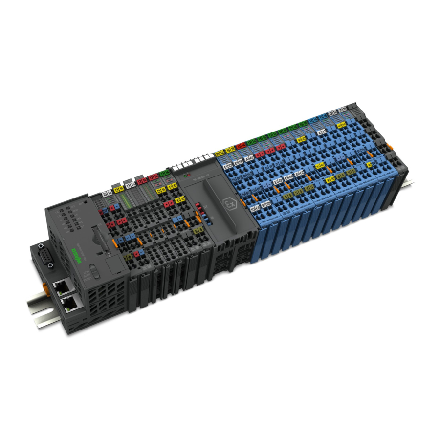
WAGO I/O System 750 XTR 750-xxxx/040-xxx System Manual XTR System Description The 750 XTR Series is part of the WAGO I/O System 750. The WAGO I/O System 750 is a modular, fieldbus-independent input/output system (I/O system). The configuration described here consists of a fieldbus coupler/controller (1) and the modular I/O modules (2) for any signal shapes that form the fieldbus node together. - Page 17 WAGO I/O System 750 XTR System Description 750-xxxx/040-xxx System Manual XTR The distinctiveness of the 750 XTR Series lies in its area of application in extreme environmental conditions. It is extremely temperature-resistant, immune to interference, as well as insensitive to vibrations and impulse voltages.
-
Page 18: Labeling
Table 3: Marking Symbols Symbol Contents Description “CE” mark The CE mark indicates WAGO has declared that the product conforms with the applicable requirements as set out in Community harmonization legislation per EC Regulation 765/2008, which allows the product to carry this mark. - Page 19 WAGO I/O System 750 XTR System Description 750-xxxx/040-xxx System Manual XTR Table 3: Marking Symbols Symbol Contents Description “Ex” registration icon Ex marking: The product meets the classified requirements according to ATEX and IECEx for operation in potentially explosive areas (see Section “Approvals”...
-
Page 20: Manufacturing Number
System Description WAGO I/O System 750 XTR 750-xxxx/040-xxx System Manual XTR Manufacturing Number The serial number indicates the delivery status directly after production. This number is part of the labeling on the side of each component. Figure 2: Marking Area for Serial Numbers There are two serial numbers in two rows in the side marking. -
Page 21: Update
WAGO I/O System 750 XTR System Description 750-xxxx/040-xxx System Manual XTR Update For products that can be updated, the side inscription has a prepared matrix in which the current update data can be entered in columns. Up to 2015, the matrix has rows to enter the “NO” work order number (or “BA” to CW 13/2004), “DS”... -
Page 22: Assembly Guidelines/Standards
System Description WAGO I/O System 750 XTR 750-xxxx/040-xxx System Manual XTR Assembly Guidelines/Standards • DIN 60204 Electrical equipment of machines • DIN EN 50178 Electronic equipment for use in power installations (replacement for VDE 0160) • EN 60439 Low-voltage switchgear and controlgear assemblies Manual Version 1.3.0... -
Page 23: Technical Data
WAGO I/O System 750 XTR System Description 750-xxxx/040-xxx System Manual XTR Technical Data Refer to the relevant manuals for current values! If the technical data of product differ from the values described here, the technical data shown in the manuals of the respective products shall be valid. -
Page 24: Electrical Safety
System Description WAGO I/O System 750 XTR 750-xxxx/040-xxx System Manual XTR 3.6.2 Electrical Safety Table 6: Technical Data – Electrical Safety Clearance/creepage distances Acc. EN 60255-5, EN 60664-1, EN 50178, IEEE C37.90 and EN 61010-2-201 Pollution degree Rated voltage AC/ DC U <... -
Page 25: Climatic Environmental Conditions
WAGO I/O System 750 XTR System Description 750-xxxx/040-xxx System Manual XTR 3.6.4 Climatic Environmental Conditions Table 10: Technical Data – Climatic Environmental Conditions Surrounding air temperature, −40 °C … +70 °C operation Surrounding air temperature, storage −40 °C … +85 °C... -
Page 26: Residential Use
In Germany, the Federal Office for Post and Telecommunications and its extensions issue the individual approval. Use of other fieldbus couplers/controllers is possible under certain conditions. Please contact WAGO Kontakttechnik GmbH & Co. KG. Manual Version 1.3.0... -
Page 27: Example Dimensions
WAGO I/O System 750 XTR System Description 750-xxxx/040-xxx System Manual XTR 3.6.6 Example Dimensions Figure 5: Dimensions – Nodes with Fieldbus Coupler/Controller (Example) Manual Version 1.3.0... -
Page 28: Standards And Approvals
WAGO I/O System 750 XTR 750-xxxx/040-xxx System Manual XTR Standards and Approvals The WAGO I/O System 750 XTR series was tested according to the following standards and guidelines. The test values are available in the manual of the respective I/O module or fieldbus coupler/controller:... -
Page 29: Table 12: Emc
WAGO I/O System 750 XTR Standards and Approvals 750-xxxx/040-xxx System Manual XTR Table 12: EMC Range acc. standard Title EMC immunity to EN 61000-6-1 EMC – Generic Standard – Immunity interference for residential environments EN 61000-6-2 EMC – Generic Standard – Immunity... -
Page 30: Table 13: Standards And Rated Conditions For Explosion Protection
Standards and Approvals WAGO I/O System 750 XTR 750-xxxx/040-xxx System Manual XTR Table 13: Standards and Rated Conditions for Explosion Protection Applications – XTR Standard ATEX acc. Directive 2014/34/EU General Requirements EN 60079-0:2012 + A11:2013 Group II electrical equipment Equipment requirements in the types of protection EN 60079-7:2015 Electrical equipment in “e”... -
Page 31: Table 15: Standards And Rated Conditions For Rail Applications
HL3 12 Documentation According to annex G MTBF values (acc. to MIL-HDBK-217-F2) are available and can be provided on request for specific projects WAGO is a company certified in accordance with the IRIS quality standard. Manual Version 1.3.0... -
Page 32: Mounting
Mounting WAGO I/O System 750 XTR 750-xxxx/040-xxx System Manual XTR Mounting Mounting Position 5.1.1 Coordinates Model Figure 6: Coordinates Model: Width (x), Height (y), Depth (z) • Width = dimension in the direction of the x-axis = horizontal in nominal mounting position, parallel to the longitudinal axis of the mounting rail •... -
Page 33: Figure 7: Mounting Positions
WAGO I/O System 750 XTR Mounting 750-xxxx/040-xxx System Manual XTR Figure 7: Mounting Positions Use an end stop in the case of vertical installation! When mounting in the “vertical top” or “vertical bottom" mounting position, also mount an end stop below the fieldbus node to protect the fieldbus node against sliding. -
Page 34: Overall Configuration
Mounting WAGO I/O System 750 XTR 750-xxxx/040-xxx System Manual XTR Overall Configuration The maximum total length of a fieldbus node without fieldbus coupler/controller is 780 mm including end module. The width of the end module is 12 mm. When assembled, the I/O modules have a maximum length of 768 mm. -
Page 35: Mounting Onto Carrier Rail
WAGO Kontakttechnik GmbH & Co. KG supplies standardized carrier rails that are optimal for use with the I/O system. If other carrier rails are used, then a technical inspection and approval of the rail by WAGO Kontakttechnik GmbH & Co. KG should take place. -
Page 36: Wago Din Rail
When using the PFC200 750-8206/040-00x or 750-821x/040-010, carrier rails without an oblong hole with a material thickness of min. 2.3 mm must also be used. Table 17: Permissible WAGO Carrier Rails When Using XTR PFC200 for Vibration Loads >4g Item 750-8202/040-00x... -
Page 37: Spacing
WAGO I/O System 750 XTR Mounting 750-xxxx/040-xxx System Manual XTR Spacing The spacing between adjacent components, cable conduits, casing and frame sides must be maintained for the complete fieldbus node. Figure 8: Spacing The spacing creates room for heat transfer, installation or wiring. The spacing to cable conduits also prevents conducted electromagnetic interferences from influencing the operation. -
Page 38: Mounting Sequence
WAGO I/O System 750 XTR 750-xxxx/040-xxx System Manual XTR Mounting Sequence Fieldbus couplers, controllers and I/O modules of the WAGO I/O System 750 are snapped directly on a carrier rail in accordance with the European standard EN 60175 (DIN 35). - Page 39 Always plug a bus end module 750-600/040-00x onto the end of the fieldbus node! You must always use this bus end module at all fieldbus nodes with the WAGO I/O System 750 XTR fieldbus couplers/controllers to guarantee proper data transfer.
-
Page 40: Inserting And Removing Devices
Mounting WAGO I/O System 750 XTR 750-xxxx/040-xxx System Manual XTR Inserting and Removing Devices Do not work when devices are energized! High voltage can cause electric shock or burns. Switch off all power to the device prior to performing any installation, repair or maintenance work. -
Page 41: Removing The Fieldbus Coupler/Controller
WAGO I/O System 750 XTR Mounting 750-xxxx/040-xxx System Manual XTR Figure 9: Turn the DIN-rail Locking Cam of the Fieldbus Coupler/Controller (Example) 5.6.2 Removing the Fieldbus Coupler/Controller Use a screwdriver blade to turn the locking disc(s) until the nose(s) of the DIN-rail locking cam(s) no longer engages behind the carrier rail. -
Page 42: Inserting The I/O Module
Mounting WAGO I/O System 750 XTR 750-xxxx/040-xxx System Manual XTR 5.6.3 Inserting the I/O Module Position the I/O module in such a way that the groove and spring are connected to the preceding and following components. Figure 10: Inserting I/O Module (Example) Press the I/O module into the assembly until the I/O module snaps into the carrier rail. -
Page 43: Removing The I/O Module
WAGO I/O System 750 XTR Mounting 750-xxxx/040-xxx System Manual XTR 5.6.4 Removing the I/O Module Remove the I/O module from the assembly by pulling the release tab. Figure 12: Removing the I/O Module (Example) Electrical connections for data or power jumper contacts are disconnected when removing the I/O module. -
Page 44: Connect Devices
Connect Devices WAGO I/O System 750 XTR 750-xxxx/040-xxx System Manual XTR Connect Devices Only connect or disconnect lines when power is safely isolated! The lines to the device can carry hazardous voltages and currents. Contact with the lines when live can result in severe injury or death. Therefore, read and observe the following safety rules before you perform work on the device: Disconnect the respective system component from the power supply. -
Page 45: Power Contacts/Field Supply
WAGO I/O System 750 XTR Connect Devices 750-xxxx/040-xxx System Manual XTR Power Contacts/Field Supply Risk of injury due to sharp-edged blade contacts! The blade contacts are sharp-edged. Handle the I/O module carefully to prevent injury. Do not touch the blade contacts. -
Page 46: Connecting A Conductor To The Cage Clamp
Do not connect more than one conductor at one single connection! If more than one conductor must be routed to one connection, these must be connected in an up-circuit wiring assembly, for example using WAGO feed- through terminals. For opening the CAGE CLAMP ®... -
Page 47: Connecting A Conductor To The Push-In Cage Clamp
Do not connect more than one conductor at one single connection! If more than one conductor must be routed to one connection, these must be connected in an up-circuit wiring assembly, for example using WAGO feed- through terminals. Terminate both solid and stranded or ferruled conductors by simply pushing them in - no tool required. -
Page 48: Power Supply
Therefore, you should always dimension the overcurrent protection according to the anticipated power usage. The system and field voltage of the WAGO I/O System 750 XTR is supplied on the head stations and bus supply modules. For components that work with extra low voltage, only SELV/PELV voltage sources should be used. -
Page 49: Isolation
WAGO I/O System 750 XTR Connect Devices 750-xxxx/040-xxx System Manual XTR 6.5.2 Isolation Within the fieldbus node, there are three electrically isolated potentials: • Electrically isolated fieldbus interface via transformer • Electronics of the fieldbus couplers/controllers and the I/O modules (local bus) •... -
Page 50: System Supply
System Supply 6.5.3.1 Connection The WAGO I/O System 750 requires a 24 V direct current system supply. The power supply is provided via the fieldbus coupler/controller and, if necessary, in addition via internal system supply modules “System Power Supply 24 VDC (750-613/040-000)”. -
Page 51: Figure 19: System Supply For Fieldbus Coupler/Controller
WAGO I/O System 750 XTR Connect Devices 750-xxxx/040-xxx System Manual XTR System supply only with appropriate fuse protection! Without overcurrent protection, the electronics can be damaged. If you implement the overcurrent protection for the system supply with a fuse, a fuse, max. -
Page 52: Dimensioning
Connect Devices WAGO I/O System 750 XTR 750-xxxx/040-xxx System Manual XTR 6.5.3.2 Dimensioning Recommendation A stable power supply cannot always be assumed. Therefore, you should use regulated power supplies to ensure the quality of the supply voltage. The supply capacity of the fieldbus coupler/controller or the internal system supply module can be taken from the technical data of the components. - Page 53 WAGO I/O System 750 XTR Connect Devices 750-xxxx/040-xxx System Manual XTR Example: Calculating the total current on the Example Coupler described above: A node with the example coupler, which is described above, consists of: • 20 relay modules (750-517/xxx-xxx) •...
-
Page 54: Field Supply
Connect Devices WAGO I/O System 750 XTR 750-xxxx/040-xxx System Manual XTR 6.5.4 Field Supply 6.5.4.1 Connection Sensors and actuators can be directly connected to the relevant channel of the I/O module in 1, 2, 3 or 4 conductor connection technology. The I/O module supplies power to the sensors and actuators. - Page 55 WAGO I/O System 750 XTR Connect Devices 750-xxxx/040-xxx System Manual XTR By inserting an additional power supply module, the field supply via the power contacts is disrupted. From there a new power supply occurs which may also contain a new voltage potential.
-
Page 56: Fusing Via Power Supply Module
Connect Devices WAGO I/O System 750 XTR 750-xxxx/040-xxx System Manual XTR 6.5.4.2 Fusing via Power Supply Module Internal fusing of the field supply is possible for various field voltages via an appropriate power supply module. Table 21: Power Supply Modules Order No. -
Page 57: Figure 22: Removing The Fuse Carrier
WAGO I/O System 750 XTR Connect Devices 750-xxxx/040-xxx System Manual XTR In order to insert or change a fuse, the fuse holder may be pulled out. In order to do this, use a screwdriver for example, to reach into one of the slits (one on both sides) and pull out the holder. -
Page 58: Fusing External
The 24 V input voltage for the field supply is provided with an external fuse with max. 10 A slow, min. 30 VDC, to be secured. For the external fusing, the fuse modules of the WAGO series 282, 2006, 281 and 2002 are suitable for this purpose. -
Page 59: Figure 26: Fuse Modules For Automotive Fuses, Series 282
WAGO I/O System 750 XTR Connect Devices 750-xxxx/040-xxx System Manual XTR Figure 26: Fuse Modules for Automotive Fuses, Series 282 Figure 27: Fuse Modules for Automotive Fuses, Series 2006 Figure 28: Fuse Modules with Pivotable Fuse Carrier, Series 281 Figure 29: Fuse Modules with Pivotable Fuse Carrier, Series 2002 Manual Version 1.3.0... -
Page 60: Power Supply For Mixed Operation
6.5.5 Power Supply for Mixed Operation In a node, WAGO I/O System 750 XTR and WAGO I/O System 750 products can be used in mixed operation. The permitted environmental conditions of the node, e.g., the temperature range, then follow the components with the least ruggedness. -
Page 61: Supplementary Power Supply Regulations
6.5.6 Supplementary Power Supply Regulations The WAGO I/O ystem 750 XTR can also be used in shipbuilding applications and onshore/offshore installations (e.g., platforms, loading facilities), as well as in telecontrol applications. This is possible via certification under the standards of leading agencies such as Germanischer Lloyd and Lloyds Register. -
Page 62: Figure 30: Power Supply Concept
Connect Devices WAGO I/O System 750 XTR 750-xxxx/040-xxx System Manual XTR Figure 30: Power Supply Concept Table 24: Legende for Figure “Power Supply Concept” Pos. Description XTR Fieldbus coupler/controller Supply filter; 24 VDC; higher isolation; extreme (750-626/040-000) XTR I/O modules Filter module for field-side power supply (surge);... -
Page 63: Supply Example
WAGO I/O System 750 XTR Connect Devices 750-xxxx/040-xxx System Manual XTR 6.5.7 Supply Example Suppl Sggggggggggggggggg The system supply and the field supply shall be separated! You should separate the system supply and the field supply in order to ensure bus operation in the event of a short-circuit on the actuator side. -
Page 64: Table 25: Legend For Figure "Power Supply Example
Connect Devices WAGO I/O System 750 XTR 750-xxxx/040-xxx System Manual XTR Table 25: Legend for Figure “Power Supply Example” Item Description Power supply on the fieldbus coupler/controller via external system supply module Supply module 24 V Supply module with bus power supply 24 V... -
Page 65: Power Supply Units
Connect Devices 750-xxxx/040-xxx System Manual XTR 6.5.8 Power Supply Units The WAGO I/O System 750 XTR requires 24 VDC voltage (system supply) for operation. Recommendation A stable power supply cannot always be assumed everywhere. Therefore, you should use regulated power supplies to ensure the quality of the supply voltage. -
Page 66: Grounding
Connect Devices WAGO I/O System 750 XTR 750-xxxx/040-xxx System Manual XTR Grounding 6.6.1 Grounding the DIN Rail 6.6.1.1 Framework Assembly When setting up the framework, the carrier rail must be screwed together with the electrically conducting cabinet or housing frame. The framework or the housing must be grounded. -
Page 67: Grounding Function
WAGO I/O System 750 XTR Connect Devices 750-xxxx/040-xxx System Manual XTR 6.6.2 Grounding Function The grounding function increases the resistance against electro-magnetic interferences. Some components in the I/O system have a carrier rail contact that dissipates electro-magnetic interferences to the carrier rail. -
Page 68: Shielding
Higher shielding performance is achieved via low-impedance connection between shield and ground. For this purpose, connect the shield over a large surface area, e.g., WAGO shield connecting system. This is especially recommended for large-scale systems where equalizing current or high impulse- type currents caused by atmospheric discharge may occur. -
Page 69: Shielded Signal Lines
6.7.4 WAGO Shield Connecting System The series 790 WAGO shield connecting system consists of shield clamping saddles, busbars and various mounting carriers. These components can be used to achieve many different configurations. -
Page 70: Power Supply Concept For Xtr Ex I
Connect Devices WAGO I/O System 750 XTR 750-xxxx/040-xxx System Manual XTR Power Supply Concept for XTR Ex i Ex i XTR I/O modules shall only be supplied via “Power Supply 24 VDC Diagn for Ex i XTR Modules” Ex i XTR I/O modules shall only be operated with a “Power Supply 24 VDC Diagn for Ex i XTR Modules”... -
Page 71: Figure 36: Ex I Xtr Power Supply Concept
WAGO I/O System 750 XTR Connect Devices 750-xxxx/040-xxx System Manual XTR 606/040-000 via the power contacts designed as blade contacts. The I/O module XTR Ex i (750-xxxx/040-xxx) provides these potentials to subsequent I/O modules via the power contacts designed as spring contacts. -
Page 72: Supplementary Power Supply Regulations For Xtr Ex I
Connect Devices WAGO I/O System 750 XTR 750-xxxx/040-xxx System Manual XTR 6.8.1 Supplementary Power Supply Regulations for XTR Ex i For standard-compliant application of Ex i XTR modules in substation instrumentation and control, telecontrol systems or shipbuilding certified operation, field-side power supply filters 750-624/040-001 (Field Supply Filter 24... -
Page 73: Figure 38: Power Supply Concept, Example 2
WAGO I/O System 750 XTR Connect Devices 750-xxxx/040-xxx System Manual XTR Table 29: Legend for Figure “Power Supply Concept, Example 1” Pos. Explanation XTR fieldbus coupler/controller XTR filter module 750-626/040-000 XTR supply “Power Supply 24 VDC Diagn for Ex i XTR Modules”... -
Page 74: List Of Figures
Figure 32: Carrier Rail Contact (Example) ............67 Figure 33: Cable Shield at Ground Potential ............68 Figure 34: Examples of the WAGO Shield Connecting System ......69 Figure 35: Application of the WAGO Shield Connecting System ......69 Figure 36: Ex i XTR Power Supply Concept ............71 Figure 37: Power Supply Concept, Example 1 ...........72... -
Page 75: List Of Tables
Table 15: Standards and Rated Conditions for Rail Applications (EN 50155:2017) ..................31 Table 16: WAGO DIN Rail ..................36 Table 17: Permissible WAGO Carrier Rails When Using XTR PFC200 for Vibration Loads >4g ..................36 Table 18: Legend for Figure “System Voltage for Fieldbus Couplers/ Controllers”... - Page 76 WAGO Kontakttechnik GmbH & Co. KG Postfach 2880 • D - 32385 Minden Hansastraße 27 • D - 32423 Minden Phone: +49 571 887 – 0 Fax: +49 571 887 – 844169 E-Mail: info@wago.com Internet: www.wago.com...
Need help?
Do you have a question about the 750 XTR and is the answer not in the manual?
Questions and answers