Sign In
Upload
Manuals
Brands
Viavi Manuals
Test Equipment
8100 V2 Series
Viavi 8100 V2 Series OTDR Modules Fiber Manuals
Manuals and User Guides for Viavi 8100 V2 Series OTDR Modules Fiber. We have
2
Viavi 8100 V2 Series OTDR Modules Fiber manuals available for free PDF download: User Manual
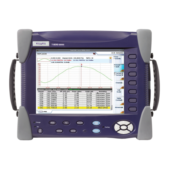
Viavi 8100 V2 Series User Manual (660 pages)
Scalable Multitest Platform
Brand:
Viavi
| Category:
Test Equipment
| Size: 5 MB
Table of Contents
Table of Contents
7
About this Guide
30
Purpose and Scope
30
Assumptions
30
Technical Assistance
30
Recycling Information
30
Conventions
31
Principles of Measurement
35
Chapter 1 Principles of Measurement
35
Principle of Reflectometry Measurements
36
Information Yielded by the Measurement
36
Validity of Measurement
37
Reflectance
37
Principle of Bi-Directional Measurement
39
Principle of the Optical Power and Attenuation Measurements
40
Power Measurement
40
Attenuation Measurements (Optical Link Loss)
40
PMD Principle
42
Method Used to Measure the PMD
43
Principle of Measurement of Chromatic Dispersion (CD ODM) Using Phase Shift Method
44
Standards and L0 for Different Types of Fiber
45
Getting Started
47
Chapter 2 Getting Started
47
Unpacking the Device - Precautions
48
Installing a Module in a Receptacle and Removing It
48
Inserting a Module
49
Removing a Module
49
Connecting Fiber Optic Cable
50
Inspecting and Cleaning Connector End Faces
50
Optical Connector Types
51
Connecting Fiber Optic Cable to Test Port
53
Optical Connectors and Interchangeable Adapters
54
Adapter Types
54
Switching Adapter Type
55
Cleaning the Universal Connector
55
Display Screen
56
Top Status Bar
57
Mini-Trace
57
Signature of the Measurement
58
Main Display Zone
58
Tabs
58
Soft Keys
59
Icons
60
Selection Keys
60
Reflectometry Measurements
61
Chapter 3 Reflectometry Measurements
61
Activating the OTDR Function
62
Selecting the Smart Test Function
62
Principle of the Smart Test
62
Selecting Smart Test
62
Selecting the Expert OTDR Function
64
Principle of the Expert OTDR
64
Selecting Expert OTDR
64
Configuring the Reflectometry Test
65
Configuring the Unit for Smart Test
65
Selecting the Configuration File
65
Modifying some Parameters before the Acquisition
66
Configuring the Test in Expert OTDR
68
Configuring the Acquisition Parameters
69
Configuring the Alarms Parameters
74
Configuring the Analysis Parameters
76
Configuring the Link Parameters
82
Configuring the File Parameters
89
Configuration in Test Auto Mode
93
Saving OTDR Configuration in a File
95
Loading an Existing OTDR Configuration File
96
Traffic Detection and Connection Quality Indicator
98
Traffic Detection
98
Connection Quality Indicator
98
Performing OTDR Acquisitions
99
Acquisition in Real Time Mode
100
Performing an Acquisition in Real Time Mode
100
Principle of Real Time Mode
100
Stopping the Real Time Acquisition
101
Performing a Measurement with Smart Test
101
Performing an Acquisition with Expert OTDR
103
Performing an Acquisition from Results Page
104
Multi-Wavelength Acquisition
105
Actions on Trace During Acquisition
106
Results Display
109
Common Functions
111
Display of Events on the Trace
111
Results Table
112
Cursors
116
Zoom Function
118
Shift Function (Expert OTDR Only)
121
Summary
121
Display of Traces in Overlay
123
Traces Display in Double Acquisition Mode
124
Advanced Functions in Expert OTDR Mode
125
Automatic Measurement and Detection
125
Addition of Events
126
Modifying Types of Events
128
Relative Measurement
128
Table Notes
130
Manual Measurements
132
Measurements of Slope
132
Measurement of ORL
134
Measurement of Reflectance
135
Splice Measurements
136
Memorization of the Position of Events
138
Overlay Trace Function
139
Display of Traces in Overlay
140
Overlaying Several Traces Stored in Memory
140
Adding Traces in Overlay
141
Swapping Overlay Traces
141
Changing the Traces Position
142
Removing a Trace
142
Quitting the Overlay Menu
143
Reference Trace Function
143
Using the Reference Trace Function in the Result Page
143
Using the Reference Trace Function in the Explorer
144
Saving the Trace(S) and Generating a Report
145
Saving Results and Creating a Report from Results Page
145
Opening a Report
148
Recalling OTDR Files
150
SLM (Smart Link Mapper) Option
150
Show the Detailed Information of One Event
152
Event View
153
Changing the Type of an Event
154
Optipulses Option
156
Configuring the OTDR Acquisition with Optipulses Mode
156
Results in Optipulses Mode
157
FTTA-SLM Option
159
Principle of FTTA-SLM
159
Acceptance Testing
160
Troubleshooting Testing
161
Configuring the Reflectometry Test for FTTA Network
162
FTTA Setup
163
Alarms Parameters
165
Analysis
166
Link Description
167
File Parameters
169
Launching the Acquisition
171
Results Page
172
Trace View
172
Smartlink View
174
Changing the Name of an Event
179
FTTH-SLM Software Option
180
Principle of FTTH
180
Configuring the Reflectometry Test for FTTH Network
181
FTTH Setup
182
Alarms Parameters
184
Link Parameters
186
File Parameters
187
Launching the Acquisition
189
Results Page
190
Trace View
191
Smartlink View
192
Changing the Type of an Event
196
Smart Link Cable Option
198
Principle of Smart Link Cable
198
Configuring the Smart Link Cable Project
199
Configuring the Project
199
Saving the Project
200
Loading an Existing Project
201
Starting Project Test Process
202
Trace Saving
203
Results of Project Cable
204
Deactivate the Fiber Test
204
Description of the Table
204
View Trace
205
Files and Project Storage
206
Text File Content
208
Reduced Dead Zone OTDR Application
209
Chapter 4 Reduced Dead Zone OTDR Application
210
Acquisition Parameters
211
Description of the RDZ Function
210
Selecting and Configuring the RDZ Function
210
Performing the Measurement
213
Performing an Acquisition from Results Page
214
Results Display
215
SLM View
218
Saving the Trace(S) and Generating a Report
218
Saving Results and Creating a Report from Results Page
219
Opening a Report
222
Chapter 5 Power Meter and Source Functions of the OTDR Modules
226
Connection to the Power Meter and the Source
226
Configuring the Power Meter
226
Configuring the Measurement Parameters of the Power Meter
226
Configuring the Alarm Parameters of the Power Meter
227
Configuring the Measurement Parameters
228
Activating the Source Function
229
Result Page
229
Result Page of the Power Meter
230
Table of Results
230
Commands of the Power Meter Parameters
231
Result Page of the Source
232
Performing the Power Level Measurement
234
Performing the Insertion Loss Measurement
234
Setting the Zero Value of the Power Meter
235
Carrying out the Reference
235
Carrying out the Side by Side Reference
235
Carrying out the Reference in Loopback Mode
237
Measurements on the Fiber under Test
238
Storing and Reloading Results
239
File Setup
239
Storing Results
239
Loading Results
240
Bi-Directional OTDR
241
Chapter 6 Bi-Directional OTDR
241
Definition of Terms Used
242
Description of the Measurement
242
Summary of the Automatic Operation Procedure
244
Configuration of Bi-Directional Measurement
244
Acquisition Parameters
245
Alarms Parameters
246
Configuration of Files Parameters
246
Performing a Bi-Directional Measurement
247
Process Display
247
Fiber Link Check
250
Measurement Process
250
Trace Display Functions
253
Origin and End Traces
254
OEO Trace
255
OEO Result Table
255
Automatic Measurement and Addition of Markers in OEO Page
256
Key Delete/Auto Meas
256
Addition of Markers
256
Markers Display
257
Test of a Cable
257
Saving the Traces and Generating a Report
258
Saving Results and Creating a Report from Results Page
258
Opening a Report
260
Recalling OEO Traces
262
Troubleshooting
263
Warning/Errors after Pressing the Key START
263
Warning/Errors Resulting from Common Configurations
264
Chapter 7 Fibercomplete Modules
265
Fibercomplete Modules
266
General Introduction
266
Principle
266
Configurations
267
Activating the Function
269
Establishing References
270
Reference Stage Process
271
Loopback Referencing Method
272
Side-By-Side Referencing Method
274
Factory References
276
Configuring the Units
276
Acquisition Parameters
277
Alarms Parameters
279
Analysis Parameters
279
Link Parameters
280
File Parameters
280
Automatic Configuration
282
Saving Parameters from Configuration
282
Loading a Configuration File Fibercomplete
284
Performing the Tests
284
Sending a Message to the Distant Platform
285
Starting the Test
286
Results Screen
288
Cable View
288
Fiber View
289
Fault Finder
289
Otdr
290
Saving Results and Generating a Report
292
Saving Results and Creating a Report from Results Page
292
Opening a Report
293
File Management
295
Storing Results
295
Filenaming Convention
295
Optical Spectrum Measurement
297
Chapter 8 Optical Spectrum Measurement
298
Laser Safety
299
Cleaning of Connectors
299
Transportation
300
Configuration of the Instrument
300
OSA Optical Spectrum Analyzer Setup
301
Loading a Configuration File
304
Acquisition Parameters
305
Analysis Parameters
309
Channel Detection
309
Osnr
311
Splitter Compensation
312
Display Parameters
313
Grid
313
Alarms
315
Zoom Mode (OSA-500)
316
Unit
317
Zoom Mode (OSA-110)
317
Saving Configuration in a File
327
Acquisition
328
Trace Display Functions
328
Display of the WDM / OSA Results
328
Display Functions
330
Zoom Function
330
Cursors Function
331
Full Scale
332
Shift Function
332
Trace /Table Key
333
Channel Detection Threshold
334
Display of a Grid
334
Display of Gain Tilt (Delta) and Gain Slope Results
335
Display of Total Power between Cursors
335
Overlay Trace Function
336
Overlaying Several Traces Stored in Memory
337
Overlaying the Current Trace
337
Display of Traces in Overlay
338
Swapping Overlay Traces
338
Changing the Traces Position
339
Trace Resulting from the Difference between Two Traces
339
Removing a Trace in Overlay
339
Quitting the Overlay Menu
340
Table of Results
340
Lines
340
Type of Display
341
On/Off-OSNR Method
342
Challenge
342
Principle of "On/Off-OSNR Measurement
342
Setup
343
Limitations
345
Channel Filtering
345
Field of Application
345
Configuration
346
Using Channel Filtering
347
Drift Measurement
347
EDFA Results Analysis
349
EDFA Test Configuration
349
EDFA Measurements
350
EDFA Results
351
DFB Results Analysis
353
DFB Test Configuration
353
DFB Measurements
353
DFB Results
354
Testing ROADM Networks
355
Measurement of I-OSNR
357
Performing an In-Band OSNR Test in I-OSNR Mode
361
File Management
362
Storing OSA Measurements
362
Recalling OSA Files
362
Polarization Mode Dispersion Measurement
363
Chapter 9 Polarization Mode Dispersion Measurement
364
Loading a Configuration File
365
Setup Menu
365
Acquisition Parameters
367
Alarms Parameters
369
Analysis Parameters
370
Saving Configuration in a File
372
Recommended Equipment
364
PMD Activation and Self Calibration
364
Performing a PMD Measurement with a PMD Test Module
373
Remote Operator
373
Local Operator
374
Performing a High Resolution PMD Measurement
375
Selecting the HR-PMD Function
375
Performing the Reference
376
Performing the Measurement
378
Display of Results
379
Spectrum/Fft Menu Key
379
Display of PMD Results
379
Cursors, in Spectrum Display
381
Trace Shift Access, in Spectrum Display
382
Zoom Access, in Spectrum Display
382
Statistics Results
382
Table of Results
383
Graphics Display
383
Information Messages
384
Saving the Trace and Generating a Report
385
Saving Results and Creating a Report from Results Page
385
Opening the Report
387
File Management
389
Saving PMD Results
389
Recalling PMD Files
389
PMD Standards and Limits
390
I-PMD Measurement
391
Chapter 10 I-PMD Measurement
391
Recommended Equipment
393
I-PMD Activation and Configuration
393
Activating the IPMD Function
393
Loading a Configuration File
394
Acquisition Parameters
395
Analysis Parameters
397
Osnr
397
Splitter Compensation
397
Display
398
Saving Configuration in a File
399
Performing a Zero Reference
400
Performing an In-Band PMD-OSNR Measurement with an I-PMD Module
401
Installation
401
Detection of Channels
402
In Band PMD-OSNR Measurement
403
Display of Results
404
OSA Results
404
OSA Menu Key
404
Moving the Cursors
407
Trace Shift
407
Zoom on Trace
407
Advanced Key
408
Channel Key
408
PMD Results
410
Performing a PMD Measurement with BBS and IPMD Module
410
Remote Operator
411
Local Operator
411
Display of Results
412
Functions on Trace Display
414
File Management
415
Saving Results
415
Recalling Files
415
PMD Standards and Limits
416
Chapter 11 High Resolution OSA Measurement
417
Cleaning of Connectors
419
Configuration of the Instrument
419
Loading a Configuration File
420
OSA Optical Spectrum Analyzer Setup
420
Acquisition Parameters
422
Analysis Parameters
424
Saving Configuration in a File
427
Trace Display Functions
428
Display of the WDM / OSA Results
428
Display Functions
430
Cursors Function
430
Zoom Function
430
Full Scale
432
Shift Function
432
Trace /Table Key
432
Channel Detection Threshold
434
Display of Total Power between Cursors
434
Acquisition
428
Overlay Trace Function
435
Overlaying Several Traces Stored in Memory
435
Overlaying the Current Trace
436
Display of Traces in Overlay
436
Changing the Traces Position
437
Swapping Overlay Traces
437
Trace Resulting from the Difference between Two Traces
437
Removing a Trace in Overlay
438
Quitting the Overlay Menu
438
Table of Results
439
On/Off-OSNR Method
441
Challenge
441
Principle of "On/Off-OSNR Measurement
441
Setup
441
Limitations
443
DFB Results Analysis
444
DFB Test Configuration
444
DFB Measurements
444
DFB Results
445
File Management
447
Storing HR-OSA Measurements
447
Recalling HR-OSA Files
447
Chapter 12 Attenuation Profile
449
Recommended Equipment
450
AP Activation and Self Calibration
450
Loading a Configuration File
450
Setup Menu
451
Test Auto Configuration
452
Acquisition Parameters
452
Acquisition Band (with 81DISPAP Modules)
452
Averaging Acquisition
453
Power Level
453
Last Reference / BBS Type / BBS Serial Number
454
Analysis Parameters
454
Measurements
454
Display
455
Saving Configuration in a File
456
AP Reference Measurement
457
Performing the Reference
457
Saving a Reference Measurement
460
Loading Existing Reference
460
Performing a AP Measurement
461
Display of AP Results
462
Trace Display
462
Spectrum/Profile
463
Trace Shift
464
Zoom
464
Cursor
465
Wavelength
465
Results Table
465
Saving the Trace and Generating a Report
467
Saving Results and Creating a Report from Results Page
467
Opening a Report
469
File Management
470
Saving Attenuation Profile Measurements
470
Recalling AP Files
471
Advertisement
Viavi 8100 V2 Series User Manual (624 pages)
Portable, modular platform designed for the construction, validation and maintenance of optical fiber networks
Brand:
Viavi
| Category:
Control Unit
| Size: 14 MB
Table of Contents
Table of Contents
7
About this Guide
33
Assumptions
34
Purpose and Scope
34
Recycling Information
34
Technical Assistance
34
Conventions
35
Principles of Measurement
37
Information Yielded by the Measurement
38
Principle of Reflectometry Measurements
38
Reflectance
39
Validity of Measurement
39
Principle of Bi-Directional Measurement
40
Attenuation Measurements (Optical Link Loss)
41
Power Measurement
41
Principle of the Optical Power and Attenuation Measurements
41
Method Used to Measure the PMD
43
PMD Principle
43
Phase Shift Method
45
Standards and L0 for Different Types of Fiber
45
Getting Started
47
Laser Classes
48
Laser Safety Instructions
48
Unpacking the Device - Precautions
48
Warning Labels for the Laser Classes
48
AC/DC Safety Information
50
Precautions Relating to Optical Connections
50
Inserting a Module
51
Installing a Module in a Receptacle and Removing It
51
Connecting Fiber Optic Cable
52
Inspecting and Cleaning Connector End Faces
52
Removing a Module
52
Optical Connector Types
53
Connecting Fiber Optic Cable to Test Port
55
Optical Connectors and Interchangeable Adapters
55
Adapter Types
56
Cleaning the Universal Connector
56
Switching Adapter Type
56
Display Screen
57
Mini-Trace
58
Signature of the Measurement
58
Top Status Bar
58
Main Display Zone
59
Tabs
59
Icons
60
Selection Keys
60
Soft Keys
60
Reflectometry Measurements
61
Activating the OTDR Function
62
Principle of the Smart Test
62
Selecting Smart Test
62
Selecting the Smart Test Function
62
Principle of the Expert OTDR
63
Selecting Expert OTDR
63
Selecting the Expert OTDR Function
63
Configuring the Reflectometry Test
64
Configuring the Unit for Smart Test
64
Modifying some Parameters before the Acquisition
65
Selecting the Configuration File
65
Configuring the Test in Expert OTDR
67
Configuring the Acquisition Parameters
68
Configuring the Alarms Parameters
72
Configuring the Analysis Parameters
74
Configuring the Link Parameters
79
Configuring the File Parameters
84
Configuration in Test Auto Mode
88
Saving OTDR Configuration in a File
89
Loading an Existing OTDR Configuration File
90
Connection Quality Indicator
92
Traffic Detection
92
Traffic Detection and Connection Quality Indicator
92
Acquisition in Real Time Mode
93
Performing an Acquisition in Real Time Mode
93
Performing OTDR Acquisitions
93
Principle of Real Time Mode
93
Performing a Measurement with Smart Test
95
Stopping the Real Time Acquisition
95
Performing an Acquisition with Expert OTDR
96
Performing an Acquisition from Results Page
97
Multi-Wavelength Acquisition
98
Actions on Trace During Acquisition
99
Saving Results for Smart Test Acquisitions
101
Results Display
103
Trace Display
103
Common Functions
104
Display of Events on the Trace
104
Results Table
105
Cursors
109
Zoom Function
111
Display of Traces in Overlay
113
Shift Function (Expert OTDR Only)
113
Smartlink View
115
Traces Display in Double Acquisition Mode
115
Show the Detailed Information of One Event
117
Event View
118
Results Table (Smart Test Mode)
120
Addition of Events
121
Advanced Functions in Expert OTDR Mode
121
Automatic Measurement and Detection
121
Relative Measurement
122
Modifying Types of Events
123
Manual Measurements
126
Measurements of Slope
126
Measurement of ORL
128
Measurement of Reflectance
129
Splice Measurements
129
Memorization of the Position of Events
131
Overlay Trace Function
132
Overlaying Several Traces Stored in Memory
132
Adding Traces in Overlay
133
Display of Traces in Overlay
133
Swapping Overlay Traces
133
Changing the Traces Position
134
Quitting the Overlay Menu
134
Removing a Trace
134
Reference Trace Function
135
Using the Reference Trace Function in the Result Page
135
Saving Results in Smart Test Mode
136
Saving the Trace(S) and Generating a Report
136
Using the Reference Trace Function in the Explorer
136
Saving Results and Creating a Report in Expert OTDR Mode
138
Opening a Report
140
Recalling OTDR Files
141
Configuring the Enterprise-SLM
142
Enterprise-SLM Software Option (T-BERD/MTS-6000A V2 Only)
142
Loading a Smartconfig
142
Principle of Enterprise-SLM
142
Acquisition
143
Alarms
145
Site Info Labels
146
File
150
Managing Projects for Multi-Fibers Testing
151
Opening an Existing Project
151
Simple OTDR Testing (for Single Fiber)
151
Creating a Project from the Setup Page
152
Project Display
153
Testing MPO
155
Description of the Table
156
Results of Project
156
Stopping the Test
156
Trace Saving
156
View Trace
157
Smartlink View
158
Configuring the OTDR Acquisition with Optipulses Mode
159
Optipulses Option
159
Results in Optipulses Mode
160
FTTA-SLM Option
161
Principle of FTTA-SLM
161
Acceptance Testing
162
Troubleshooting Testing
163
Configuring the Reflectometry Test for FTTA Network
164
FTTA Setup
165
Alarms Parameters
167
Analysis
167
Link Description
168
Launching the Acquisition
170
Results Page
172
Trace View
172
Smartlink View
173
Changing the Name of an Event
177
FTTH-SLM Software Option
178
Principle of FTTH
178
Configuring the Reflectometry Test for FTTH Network
179
FTTH Setup
179
Alarms Parameters
181
Link Parameters
182
File Parameters
183
Launching the Acquisition
185
Results Page
186
Trace View
186
Smartlink View
188
Changing the Type of an Event
191
Configuring the Project
193
Configuring the Smart Link Cable Project
193
Principle of Smart Link Cable
193
Smart Link Cable Option
193
Loading an Existing Project
195
Saving the Project
195
Starting Project Test Process
196
Deactivate the Fiber Test
198
Description of the Table
198
Results of Project Cable
198
Trace Saving
198
View Trace
199
Files and Project Storage
200
Text File Content
202
Chapter 4 Reduced Dead Zone OTDR Application
203
Description of the RDZ Function
204
Selecting and Configuring the RDZ Function
204
Acquisition Parameters
205
Performing the Measurement
207
Performing an Acquisition from Results Page
207
Results Display
208
SLM View
210
Saving the Trace(S) and Generating a Report
211
Saving Results and Creating a Report from Results Page
211
Opening a Report
214
Recalling Files
215
Power Meter and Source Functions of the OTDR Modules
217
Connection to the Power Meter and the Source
218
Configuring the Power Meter
218
Configuring the Measurement Parameters of the Power Meter
218
Configuring the Alarm Parameters of the Power Meter
219
Configuring the Measurement Parameters
220
Activating the Source Function
220
Result Page
221
Result Page of the Power Meter
221
Table of Results
221
Commands of the Power Meter Parameters
222
Result Page of the Source
223
Performing the Power Level Measurement
224
Performing the Insertion Loss Measurement
225
Setting the Zero Value of the Power Meter
225
Carrying out the Reference
225
Carrying out the Side by Side Reference
225
Carrying out the Reference in Loopback Mode
227
Measurements on the Fiber under Test
228
Storing and Reloading Results
228
File Setup
228
Storing Results
228
Loading Results
229
Bi-Directional OTDR
231
Definition of Terms Used
232
Description of the Measurement
232
Summary of the Automatic Operation Procedure
233
Configuration of Bi-Directional Measurement
234
Acquisition Parameters
235
Alarms Parameters
235
Configuration of Files Parameters
236
Performing a Bi-Directional Measurement
236
Process Display
236
Fiber Link Check
238
Measurement Process
239
Trace Display Functions
241
Origin and End Traces
242
OEO Trace
243
OEO Result Table
243
Automatic Measurement and Addition of Markers in OEO Page
243
Key Delete/Auto Meas
243
Addition of Markers
244
Markers Display
244
Test of a Cable
244
Saving the Traces and Generating a Report
245
Saving Results and Creating a Report from Results Page
245
Opening a Report
247
Recalling OEO Traces
249
Troubleshooting
249
Warning/Errors after Pressing the Key Start
249
Warning/Errors Resulting from Common Configurations
250
Fibercomplete Modules
252
General Introduction
252
Principle
252
Configurations
253
Activating the Function
255
Establishing References
255
Reference Stage Process
256
Loopback Referencing Method
257
Side-By-Side Referencing Method
259
Factory References
260
Configuring the Units
261
Acquisition Parameters
262
Alarms Parameters
263
Analysis Parameters
263
Link Parameters
264
File Parameters
264
Automatic Configuration
265
Saving Parameters from Configuration
266
Loading a Configuration File Fibercomplete
267
Performing the Tests
267
Sending a Message to the Distant Platform
268
Starting the Test
269
Results Screen
270
Cable View
270
Fiber View
271
Fault Finder
272
Otdr
273
Saving Results and Generating a Report
274
Saving Results and Creating a Report from Results Page
274
Opening a Report
276
Recalling OTDR Files
277
Filenaming Convention
277
Advertisement
Related Products
Viavi 8000 V2 Platform
Viavi T-BERD 8000
Viavi 87340
Viavi OneAdvisor 800
Viavi 8380 RPC
Viavi 8800 Series
Viavi 8800S
Viavi 8800SX
Viavi 87339
Viavi 113956
Viavi Categories
Test Equipment
Measuring Instruments
Microscope
Control Unit
Server
More Viavi Manuals
Login
Sign In
OR
Sign in with Facebook
Sign in with Google
Upload manual
Upload from disk
Upload from URL