Sign In
Upload
Manuals
Brands
Renesas Manuals
Computer Hardware
M16C/60 Series
Renesas M16C/60 Series Manuals
Manuals and User Guides for Renesas M16C/60 Series. We have
3
Renesas M16C/60 Series manuals available for free PDF download: User Manual, Hardware Manual
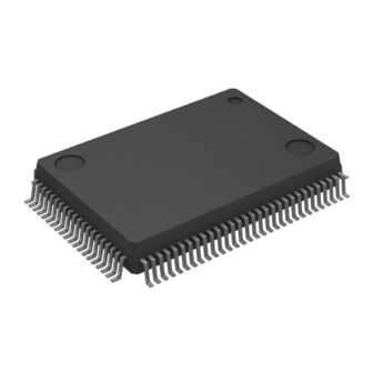
Renesas M16C/60 Series User Manual (846 pages)
Brand:
Renesas
| Category:
Computer Hardware
| Size: 10.95 MB
Table of Contents
Table of Contents
8
Quick Reference
27
Overview
34
Features
34
Applications
34
Specifications
35
Product List
37
Block Diagram
39
Pin Assignments
40
Pin Functions
44
Central Processing Unit (CPU)
47
Data Registers (R0, R1, R2, and R3)
48
Address Registers (A0 and A1)
48
Frame Base Register (FB)
48
Interrupt Table Register (INTB)
48
Program Counter (PC)
48
User Stack Pointer (USP) and Interrupt Stack Pointer (ISP)
48
Static Base Register (SB)
48
Flag Register (FLG)
48
Carry Flag (C Flag)
48
Debug Flag (D Flag)
48
Interrupt Enable Flag (I Flag)
49
Stack Pointer Select Flag (U Flag)
49
Processor Interrupt Priority Level (IPL)
49
Reserved Areas
49
Address Space
50
Memory Map
51
Accessible Area in each Mode
52
Special Function Registers (Sfrs)
53
Sfrs
53
Notes on Sfrs
71
Register Settings
71
Protection
73
Introduction
73
Register
73
Protect Register (PRCR)
73
Notes on Protection
75
Resets
76
Introduction
76
Registers
78
Processor Mode Register 0 (PM0)
79
Reset Source Determine Register (RSTFR)
80
Optional Function Select Area
81
Optional Function Select Address 1 (OFS1)
81
Operations
83
Status after Reset
83
Hardware Reset
86
Power-On Reset Function
87
Voltage Monitor 0 Reset
88
Voltage Monitor 1 Reset
88
Voltage Monitor 2 Reset
88
Oscillator Stop Detect Reset
89
Watchdog Timer Reset
89
Software Reset
89
Cold/Warm Start Discrimination
90
Notes on Resets
91
Power Supply Rising Gradient
91
Power-On Reset
91
OSDR Bit (Oscillation Stop Detect Reset Detect Flag)
92
Voltage Detector
93
Introduction
93
Registers
95
Voltage Detector 2 Flag Register (VCR1)
96
Voltage Detector Operation Enable Register (VCR2)
97
Voltage Monitor Function Select Register (VWCE)
98
Voltage Detector 1 Level Select Register (VD1LS)
99
Voltage Monitor 0 Control Register (VW0C)
100
Voltage Monitor 1 Control Register (VW1C)
101
Voltage Monitor 2 Control Register (VW2C)
103
Optional Function Select Area
105
Optional Function Select Address 1 (OFS1)
105
Operations
106
Digital Filter
106
Voltage Detector 0
107
Voltage Detector 1
109
Voltage Detector 2
112
Interrupts
115
Clock Generator
116
Introduction
116
Registers
118
Processor Mode Register 0 (PM0)
119
System Clock Control Register 0 (CM0)
120
System Clock Control Register 1 (CM1)
122
Oscillation Stop Detection Register (CM2)
124
Peripheral Clock Select Register (PCLKR)
126
Peripheral Clock Stop Register 1 (PCLKSTP1)
126
PLL Control Register 0 (PLC0)
128
Processor Mode Register 2 (PM2)
129
Clocks Generated by Clock Generators
130
Main Clock
130
PLL Clock
131
125 Khz On-Chip Oscillator Clock (Foco-S)
131
Sub Clock (Fc)
132
CPU Clock and Peripheral Function Clocks
133
CPU Clock and BCLK
133
Peripheral Function Clocks (F1, Foco-S, Fc32, Fc, Main Clock)
133
Clock Output Function
135
System Clock Protection Function
135
Oscillator Stop/Restart Detect Function
136
Operation When CM27 Bit Is 0 (Oscillator Stop Detect Reset)
136
Operation When CM27 Bit Is 1 (Oscillator Stop/Restart Detect Interrupt)
137
Using the Oscillator Stop/Restart Detect Function
138
Interrupt
138
Notes on Clock Generator
139
Oscillator Using a Crystal or a Ceramic Resonator
139
Noise Countermeasure
140
CPU Clock
141
Oscillator Stop/Restart Detect Function
141
PLL Frequency Synthesizer
142
Power Control
143
Introduction
143
Registers
143
Flash Memory Control Register 0 (FMR0)
144
Flash Memory Control Register 2 (FMR2)
145
Clock
147
Normal Operating Mode
147
CPU Clock
149
Clock Mode Transition Procedure
151
Wait Mode
154
Stop Mode
156
Power Control in Flash Memory
158
Stopping Flash Memory
158
Reading Flash Memory
159
Low Current Consumption Read Mode
160
Reducing Power Consumption
161
Ports
161
A/D Converter
161
D/A Converter
161
Stopping Peripheral Functions
161
Switching the Oscillation-Driving Capacity
161
Notes on Power Control
162
CPU Clock
162
Wait Mode
162
Stop Mode
162
Low Current Consumption Read Mode
163
Slow Read Mode
163
10. Processor Mode
164
Introduction
164
Registers
165
Processor Mode Register 0 (PM0)
165
Processor Mode Register 1 (PM1)
166
Program 2 Area Control Register (PRG2C)
168
Operations
169
Processor Mode Settings
169
11. Bus
171
Introduction
171
Registers
171
Chip Select Control Register (CSR)
172
Chip Select Expansion Control Register (CSE)
173
Operations
174
Common Specifications between the Internal Bus and External Bus
174
Internal Bus
175
External Bus
176
External Bus Mode
176
External Bus Control
177
Notes on Bus
186
Reading Data Flash
186
External Bus
186
External Access Immediately after Writing to the Sfrs
186
Hold
186
12. Memory Space Expansion Function
187
Introduction
187
Registers
187
Data Bank Register (DBR)
188
Operations
189
1-MB Mode
189
4-MB Mode
191
13. Programmable I/O Ports
198
Introduction
198
I/O Ports and Pins
199
Registers
211
Pull-Up Control Register 0 (PUR0)
212
Pull-Up Control Register 1 (PUR1)
213
Pull-Up Control Register 2 (PUR2)
214
Port Control Register (PCR)
215
Port Pi Register (Pi) (I = 0 to 10)
216
Port Pi Direction Register (Pdi) (I = 0 to 10)
217
NMI/SD Digital Filter Register (NMIDF)
218
Peripheral Function I/O
219
Peripheral Function I/O and Port Direction Bits
219
Priority Level of Peripheral Function I/O
219
NMI/SD Digital Filter
220
CNVSS Pin
220
Unassigned Pin Handling
221
Notes on Programmable I/O Ports
223
Influence of SD
223
Influence of SI/O3 and SI/O4
223
Interrupts
224
Introduction
224
Registers
225
Processor Mode Register 2 (PM2)
227
Interrupt Control Register 1
228
(INT7IC, INT6IC, INT3IC, S4IC/INT5IC, S3IC/INT4IC, INT0IC to INT2IC)
229
Interrupt Source Select Register 3 (IFSR3A)
230
Interrupt Source Select Register 2 (IFSR2A)
231
Interrupt Source Select Register (IFSR)
232
Address Match Interrupt Enable Register (AIER)
233
Address Match Interrupt Enable Register 2 (AIER2)
233
Address Match Interrupt Register I (Rmadi) (I = 0 to 3)
234
Port Control Register (PCR)
235
NMI/SD Digital Filter Register (NMIDF)
236
Types of Interrupts
237
Software Interrupts
238
Undefined Instruction Interrupt
238
Overflow Interrupt
238
BRK Interrupt
238
INT Instruction Interrupt
238
Hardware Interrupts
239
Special Interrupts
239
Peripheral Function Interrupts
239
Interrupts and Interrupt Vectors
240
Fixed Vector Tables
240
Relocatable Vector Tables
241
Interrupt Control
243
Maskable Interrupt Control
243
Interrupt Sequence
244
Interrupt Response Time
245
Variation of IPL When Interrupt Request Is Accepted
245
Saving Registers
246
Returning from an Interrupt Routine
247
Interrupt Priority
247
Interrupt Priority Level Select Circuit
247
Multiple Interrupts
249
INT Interrupt
249
NMI Interrupt
250
14.10 Key Input Interrupt
250
14.11 Address Match Interrupt
251
14.12 Non-Maskable Interrupt Source Discrimination
252
14.13 Notes on Interrupts
253
14.13.1 Reading Address 00000H
253
14.13.2 SP Setting
253
14.13.3 NMI Interrupt
253
14.13.4 Changing an Interrupt Source
254
14.13.5 Rewriting the Interrupt Control Register
255
14.13.6 Instruction to Rewrite the Interrupt Control Register
255
14.13.7 INT Interrupt
256
15. Watchdog Timer
257
Introduction
257
Registers
258
Voltage Monitor 2 Control Register (VW2C)
258
Count Source Protection Mode Register (CSPR)
259
Watchdog Timer Refresh Register (WDTR)
260
Watchdog Timer Start Register (WDTS)
260
Watchdog Timer Control Register (WDC)
261
Optional Function Select Area
262
Optional Function Select Address 1 (OFS1)
262
Operations
263
Count Source Protection Mode Disabled
263
Count Source Protection Mode Enabled
264
Interrupts
265
Notes on the Watchdog Timer
266
16. Dmac
267
Introduction
267
Registers
269
Dmai Source Pointer (Sari) (I = 0 to 3)
270
Dmai Destination Pointer (Dari) (I = 0 to 3)
270
Dmai Transfer Counter (Tcri) (I = 0 to 3)
271
Dmai Control Register (Dmicon) (I = 0 to 3)
272
Dmai Source Select Register (Dmisl) (I = 0 to 3)
273
Operations
276
DMA Enabled
276
DMA Request
276
Transfer Cycles
277
DMAC Transfer Cycles
279
Single Transfer Mode
280
Repeat Transfer Mode
281
Channel Priority and DMA Transfer Timing
282
Interrupts
283
Notes on DMAC
284
Write to the DMAE Bit in the Dmicon Register (I = 0 to 3)
284
Changing the DMA Request Source
284
17. Timer a
285
Introduction
285
Registers
288
Peripheral Clock Select Register (PCLKR)
289
Clock Prescaler Reset Flag (CPSRF)
289
Peripheral Clock Stop Register 1 (PCLKSTP1)
290
Timer a Count Source Select Register I (Tacsi) (I = 0 to 2)
291
16-Bit Pulse Width Modulation Mode Function Select Register (PWMFS)
292
Timer a Waveform Output Function Select Register (TAPOFS)
293
Timer a Output Waveform Change Enable Register (TAOW)
294
Timer Ai Register (Tai) (I = 0 to 4)
295
Timer Ai-1 Register (Tai1) (I = 1, 2, 4)
296
Count Start Flag (TABSR)
296
One-Shot Start Flag (ONSF)
297
Trigger Select Register (TRGSR)
298
Increment/Decrement Flag (UDF)
299
Timer Ai Mode Register (Taimr) (I = 0 to 4)
300
Operations
301
Common Operations
301
Timer Mode
303
Event Counter Mode (When Not Using Two-Phase Pulse Signal Processing)
307
Event Counter Mode (When Processing Two-Phase Pulse Signal)
311
One-Shot Timer Mode
316
Pulse Width Modulation (PWM) Mode
320
Programmable Output Mode (Timers A1, A2, and A4)
325
Interrupts
329
Notes on Timer a
330
Common Notes on Multiple Modes
330
Timer a (Timer Mode)
331
Timer a (Event Counter Mode)
331
Timer a (One-Shot Timer Mode)
331
Timer a (Pulse Width Modulation Mode)
332
Timer a (Programmable Output Mode)
333
18. Timer B
334
Introduction
334
Registers
337
Peripheral Clock Select Register (PCLKR)
338
Clock Prescaler Reset Flag (CPSRF)
338
Peripheral Clock Stop Register 1 (PCLKSTP1)
339
Timer Bi Register (Tbi) (I = 0 to 5)
340
Timer Bi-1 Register (Tbi1) (I = 0 to 5)
341
Pulse Period/Pulse Width Measurement Mode Function Select Register I (Ppwfsi) (I = 1, 2)
342
Timer B Count Source Select Register I (Tbcsi) (I = 0 to 3)
343
Count Start Flag (TABSR) Timer B3/B4/B5 Count Start Flag (TBSR)
344
Timer Bi Mode Register (Tbimr) (I = 0 to 5)
345
Operations
346
Common Operations
346
Timer Mode
348
Event Counter Mode
350
Pulse Period/Pulse Width Measurement Modes
353
Interrupts
358
Notes on Timer B
359
Common Notes on Multiple Modes
359
Timer B (Timer Mode)
359
Timer B (Event Counter Mode)
359
Timer B (Pulse Period/Pulse Width Measurement Modes)
360
19. Three-Phase Motor Control Timer Function
361
Introduction
361
Registers
365
Timer B2 Register (TB2)
366
Timer Ai, Ai-1 Register (Tai, Tai1) (I = 1, 2, 4)
366
Three-Phase PWM Control Register 0 (INVC0)
367
Three-Phase PWM Control Register 1 (INVC1)
369
Three-Phase Output Buffer Register I (Idbi) (I = 0, 1)
371
Dead Time Timer (DTT)
371
Timer B2 Interrupt Generation Frequency Set Counter (ICTB2)
372
Timer B2 Special Mode Register (TB2SC)
373
Position-Data-Retain Function Control Register (PDRF)
374
Port Function Control Register (PFCR)
375
Three-Phase Protect Control Register (TPRC)
375
Operations
376
Common Operations in Multiple Modes
376
Triangular Wave Modulation Three-Phase Mode 0
382
Triangular Wave Modulation Three-Phase Mode 1
387
Sawtooth Wave Modulation Mode
394
Interrupts
399
Timer B2 Interrupt
399
Timer A1, A2, and A4 Interrupts
399
Notes on Three-Phase Motor Control Timer Function
400
Timer a and Timer B
400
Influence of SD
400
20. Real-Time Clock
401
Introduction
401
Registers
403
Real-Time Clock Second Data Register (RTCSEC)
404
Real-Time Clock Minute Data Register (RTCMIN)
405
Real-Time Clock Hour Data Register (RTCHR)
406
Real-Time Clock Day Data Register (RTCWK)
407
Real-Time Clock Control Register 1 (RTCCR1)
408
Real-Time Clock Control Register 2 (RTCCR2)
410
Real-Time Clock Count Source Select Register (RTCCSR)
412
Real-Time Clock Second Compare Data Register (RTCCSEC)
413
Real-Time Clock Minute Compare Data Register (RTCCMIN)
414
Real-Time Clock Hour Compare Data Register (RTCCHR)
415
Operations
416
Basic Operation
416
Compare Mode
419
Interrupts
425
Notes on Real-Time Clock
426
Starting and Stopping the Count
426
Register Settings (Time Data, Etc.)
426
Register Settings (Compare Data)
426
Time Reading Procedure in Real-Time Clock Mode
427
21. Pulse Width Modulator
428
Introduction
428
Registers
429
PWM Control Register 0 (PWMCON0)
430
Pwmi Prescaler (Pwmprei) (I = 0, 1)
431
Pwmi Register (Pwmregi) (I = 0, 1)
431
PWM Control Register 1 (PWMCON1)
432
Operations
433
Setting Procedure
433
Operation Example
433
22. Remote Control Signal Receiver
435
Introduction
435
Registers
438
Pmci Function Select Register 0 (Pmcicon0) (I = 0, 1)
440
Pmci Function Select Register 1 (Pmcicon1) (I = 0, 1)
442
Pmci Function Select Register 2 (Pmcicon2) (I = 0, 1)
444
Pmci Function Select Register 3 (Pmcicon3) (I = 0, 1)
446
Pmci Status Register (Pmcists) (I = 0, 1)
447
Pmci Interrupt Source Register (Pmciint) (I = 0, 1)
450
Pmci Header Pattern Set Register (MIN) (Pmcihdpmin) (I = 0, 1) Pmci Header Pattern Set Register (MAX) (Pmcihdpmax) (I = 0, 1)
451
Pmci Data 0 Pattern Set Register (MIN) (Pmcid0Pmin) (I = 0, 1) Pmci Data 0 Pattern Set Register (MAX) (Pmcid0Pmax) (I = 0, 1) Pmci Data 1 Pattern Set Register (MIN) (Pmcid1Pmin) (I = 0, 1) Pmci Data 1 Pattern Set Register (MAX) (Pmcid1Pmax) (I = 0, 1)
453
Pmci Measurements Register (Pmcitim) (I = 0, 1)
454
PMC0 Receive Bit Count Register (PMC0RBIT)
454
PMC0 Receive Data Store Register I (Pmc0Dati) (I = 0 to 5)
455
PMC0 Compare Control Register (PMC0CPC)
456
PMC0 Compare Data Register (PMC0CPD)
457
Operations
458
Common Operations in Multiple Modes
458
Pattern Match Mode (PMC0 and PMC1 Operate Independently)
460
Pattern Match Mode (Combined Operation of PMC0 and PMC1)
466
Input Capture Mode (Operating PMC0 and PMC1 Independently)
471
Input Capture Mode (Simultaneous Count Operation of PMC0 and PMC1)
475
Interrupts
478
Notes on Remote Control Signal Receiver
481
Starting/Stopping Pmci
481
Reading the Register
481
Rewriting the Register
481
Combined Operation
482
Serial Interface Uarti (I = 0 to 2, 5 to 7)
483
Introduction
483
Registers
488
Peripheral Clock Select Register (PCLKR)
490
Uarti Transmit/Receive Mode Register (Uimr) (I = 0 to 2, 5 to 7)
491
Uarti Bit Rate Register (Uibrg) (I = 0 to 2, 5 to 7)
492
Uarti Transmit Buffer Register (Uitb) (I = 0 to 2, 5 to 7)
492
Uarti Transmit/Receive Control Register 0 (Uic0) (I = 0 to 2, 5 to 7)
493
Uarti Transmit/Receive Control Register 1 (Uic1) (I = 0 to 2, 5 to 7)
495
Uarti Receive Buffer Register (Uirb) (I = 0 to 2, 5 to 7)
496
UART Transmit/Receive Control Register 2 (UCON)
498
Uarti Special Mode Register 4 (Uismr4) (I = 0 to 2, 5 to 7)
499
Uarti Special Mode Register 3 (Uismr3) (I = 0 to 2, 5 to 7)
501
Uarti Special Mode Register 2 (Uismr2) (I = 0 to 2, 5 to 7)
502
Uarti Special Mode Register (Uismr) (I = 0 to 2, 5 to 7)
503
Operations
504
Clock Synchronous Serial I/O Mode
504
Clock Asynchronous Serial I/O (UART) Mode
512
Advertisement
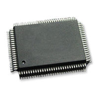
Renesas M16C/60 Series User Manual (853 pages)
Brand:
Renesas
| Category:
Microcontrollers
| Size: 10.91 MB
Table of Contents
Table of Contents
8
Quick Reference
27
1 Overview
34
Features
34
Applications
34
Specifications
35
Product List
37
Block Diagram
39
Pin Assignments
40
Pin Functions
44
2 Central Processing Unit (CPU)
47
Data Registers (R0, R1, R2, and R3)
48
Address Registers (A0 and A1)
48
Frame Base Register (FB)
48
Interrupt Table Register (INTB)
48
Program Counter (PC)
48
User Stack Pointer (USP) and Interrupt Stack Pointer (ISP)
48
Static Base Register (SB)
48
Flag Register (FLG)
48
Carry Flag (C Flag)
48
Debug Flag (D Flag)
48
Interrupt Enable Flag (I Flag)
49
Stack Pointer Select Flag (U Flag)
49
Processor Interrupt Priority Level (IPL)
49
Reserved Areas
49
3 Address Space
50
Memory Map
51
Accessible Area in each Mode
52
4 Special Function Registers (Sfrs)
53
Sfrs
53
Notes on Sfrs
71
Register Settings
71
5 Protection
73
Introduction
73
Register
73
Protect Register (PRCR)
73
Notes on Protection
75
6 Resets
76
Introduction
76
Registers
78
Processor Mode Register 0 (PM0)
79
Reset Source Determine Register (RSTFR)
80
Optional Function Select Area
81
Optional Function Select Address 1 (OFS1)
81
Operations
83
Status after Reset
83
Hardware Reset
86
Power-On Reset Function
87
Voltage Monitor 0 Reset
88
Voltage Monitor 1 Reset
88
Voltage Monitor 2 Reset
88
Oscillator Stop Detect Reset
89
Watchdog Timer Reset
89
Software Reset
89
Cold/Warm Start Discrimination
90
Notes on Resets
91
Power Supply Rising Gradient
91
Power-On Reset
91
OSDR Bit (Oscillation Stop Detect Reset Detect Flag)
92
Hardware Reset When VCC1 < Vdet0
92
7 Voltage Detector
93
Introduction
93
Registers
95
Voltage Detector 2 Flag Register (VCR1)
96
Voltage Detector Operation Enable Register (VCR2)
97
Voltage Monitor Function Select Register (VWCE)
98
Voltage Detector 1 Level Select Register (VD1LS)
99
Voltage Monitor 0 Control Register (VW0C)
100
Voltage Monitor 1 Control Register (VW1C)
101
Voltage Monitor 2 Control Register (VW2C)
103
Optional Function Select Area
105
Optional Function Select Address 1 (OFS1)
105
Operations
106
Digital Filter
106
Voltage Detector 0
107
Voltage Detector 1
109
Voltage Detector 2
112
Interrupts
115
8 Clock Generator
116
Introduction
116
Registers
118
Processor Mode Register 0 (PM0)
119
System Clock Control Register 0 (CM0)
120
System Clock Control Register 1 (CM1)
122
Oscillation Stop Detection Register (CM2)
124
Peripheral Clock Select Register (PCLKR)
126
PLL Control Register 0 (PLC0)
127
Processor Mode Register 2 (PM2)
128
Clocks Generated by Clock Generators
129
Main Clock
129
PLL Clock
130
125 Khz On-Chip Oscillator Clock (Foco-S)
130
Sub Clock (Fc)
131
CPU Clock and Peripheral Function Clocks
132
CPU Clock and BCLK
132
Peripheral Function Clocks (F1, Foco-S, Fc32, Fc)
132
Clock Output Function
134
System Clock Protection Function
134
Oscillator Stop/Restart Detect Function
135
Operation When CM27 Bit Is 0 (Oscillator Stop Detect Reset)
135
Operation When CM27 Bit Is 1 (Oscillator Stop/Restart Detect Interrupt)
136
Using the Oscillator Stop/Restart Detect Function
137
Interrupt
137
Notes on Clock Generator
138
Oscillator Using a Crystal or a Ceramic Resonator
138
Noise Countermeasure
139
CPU Clock
140
Oscillator Stop/Restart Detect Function
140
PLL Frequency Synthesizer
141
Starting PLL Clock Oscillation
142
9 Power Control
143
Introduction
143
Registers
143
Flash Memory Control Register 0 (FMR0)
144
Flash Memory Control Register 2 (FMR2)
145
Clock
147
Normal Operating Mode
147
CPU Clock
149
Clock Mode Transition Procedure
151
Wait Mode
154
Stop Mode
156
Power Control in Flash Memory
158
Stopping Flash Memory
158
Reading Flash Memory
159
Low Current Consumption Read Mode
160
Reducing Power Consumption
161
Ports
161
A/D Converter
161
D/A Converter
161
Stopping Peripheral Functions
161
Switching the Oscillation-Driving Capacity
161
Notes on Power Control
162
CPU Clock
162
Wait Mode
162
Stop Mode
162
Low Current Consumption Read Mode
163
Slow Read Mode
163
10 Processor Mode
164
Introduction
164
Registers
165
Processor Mode Register 0 (PM0)
165
Processor Mode Register 1 (PM1)
166
Program 2 Area Control Register (PRG2C)
168
Operations
169
Processor Mode Settings
169
11 Bus
171
Introduction
171
Registers
171
Chip Select Control Register (CSR)
172
Chip Select Expansion Control Register (CSE)
173
Operations
174
Common Specifications between the Internal Bus and External Bus
174
Internal Bus
175
External Bus
176
External Bus Mode
176
External Bus Control
177
Notes on Bus
186
Reading Data Flash
186
External Bus
186
External Access Immediately after Writing to the Sfrs
186
Hold
186
12 Memory Space Expansion Function
187
Introduction
187
Registers
187
Data Bank Register (DBR)
188
Operations
189
1-MB Mode
189
4-MB Mode
191
13 Programmable I/O Ports
198
Introduction
198
I/O Ports and Pins
199
Registers
211
Pull-Up Control Register 0 (PUR0)
212
Pull-Up Control Register 1 (PUR1)
213
Pull-Up Control Register 2 (PUR2)
214
Port Control Register (PCR)
215
Port Pi Register (Pi) (I = 0 to 10)
216
Port Pi Direction Register (Pdi) (I = 0 to 10)
217
NMI/SD Digital Filter Register (NMIDF)
218
Peripheral Function I/O
219
Peripheral Function I/O and Port Direction Bits
219
Priority Level of Peripheral Function I/O
219
NMI/SD Digital Filter
220
CNVSS Pin
220
Unassigned Pin Handling
221
Notes on Programmable I/O Ports
223
Influence of SD
223
Influence of SI/O3 and SI/O4
223
14 Interrupts
224
Introduction
224
Registers
225
Processor Mode Register 2 (PM2)
227
Interrupt Control Register 1
228
(INT7IC, INT6IC, INT3IC, S4IC/INT5IC, S3IC/INT4IC, INT0IC to INT2IC)
229
Interrupt Source Select Register 3 (IFSR3A)
230
Interrupt Source Select Register 2 (IFSR2A)
231
Interrupt Source Select Register (IFSR)
232
Address Match Interrupt Enable Register (AIER)
233
Address Match Interrupt Enable Register 2 (AIER2)
233
Address Match Interrupt Register I (Rmadi) (I = 0 to 3)
234
Port Control Register (PCR)
235
NMI/SD Digital Filter Register (NMIDF)
236
Types of Interrupts
237
Software Interrupts
238
Undefined Instruction Interrupt
238
Overflow Interrupt
238
BRK Interrupt
238
INT Instruction Interrupt
238
Hardware Interrupts
239
Special Interrupts
239
Peripheral Function Interrupts
239
Interrupts and Interrupt Vectors
240
Fixed Vector Tables
240
Relocatable Vector Tables
241
Interrupt Control
243
Maskable Interrupt Control
243
Interrupt Sequence
244
Interrupt Response Time
245
Variation of IPL When Interrupt Request Is Accepted
245
Saving Registers
246
Returning from an Interrupt Routine
247
Interrupt Priority
247
Interrupt Priority Level Select Circuit
247
Multiple Interrupts
249
INT Interrupt
249
NMI Interrupt
250
14.10 Key Input Interrupt
250
14.11 Address Match Interrupt
251
14.12 Non-Maskable Interrupt Source Discrimination
252
14.13 Notes on Interrupts
253
14.13.1 Reading Address 00000H
253
14.13.2 SP Setting
253
14.13.3 NMI Interrupt
253
14.13.4 Changing an Interrupt Source
254
14.13.5 Rewriting the Interrupt Control Register
255
14.13.6 Instruction to Rewrite the Interrupt Control Register
255
14.13.7 INT Interrupt
256
15 Watchdog Timer
257
Introduction
257
Registers
258
Voltage Monitor 2 Control Register (VW2C)
258
Count Source Protection Mode Register (CSPR)
259
Watchdog Timer Refresh Register (WDTR)
260
Watchdog Timer Start Register (WDTS)
260
Watchdog Timer Control Register (WDC)
261
Optional Function Select Area
262
Optional Function Select Address 1 (OFS1)
262
Operations
263
Count Source Protection Mode Disabled
263
Count Source Protection Mode Enabled
264
Interrupts
265
Notes on the Watchdog Timer
266
16 Dmac
267
Introduction
267
Registers
269
Dmai Source Pointer (Sari) (I = 0 to 3)
270
Dmai Destination Pointer (Dari) (I = 0 to 3)
270
Dmai Transfer Counter (Tcri) (I = 0 to 3)
271
Dmai Control Register (Dmicon) (I = 0 to 3)
272
Dmai Source Select Register (Dmisl) (I = 0 to 3)
273
Operations
276
DMA Enabled
276
DMA Request
276
Transfer Cycles
277
DMAC Transfer Cycles
279
Single Transfer Mode
280
Repeat Transfer Mode
281
Channel Priority and DMA Transfer Timing
282
Interrupts
283
Notes on DMAC
284
Write to the DMAE Bit in the Dmicon Register (I = 0 to 3)
284
Changing the DMA Request Source
284
17 Timer a
285
Introduction
285
Registers
288
Peripheral Clock Select Register (PCLKR)
289
Clock Prescaler Reset Flag (CPSRF)
289
Timer a Count Source Select Register I (Tacsi) (I = 0 to 2)
290
16-Bit Pulse Width Modulation Mode Function Select Register (PWMFS)
291
Timer a Waveform Output Function Select Register (TAPOFS)
292
Timer a Output Waveform Change Enable Register (TAOW)
293
Timer Ai Register (Tai) (I = 0 to 4)
294
Timer Ai-1 Register (Tai1) (I = 1, 2, 4)
295
Count Start Flag (TABSR)
295
One-Shot Start Flag (ONSF)
296
Trigger Select Register (TRGSR)
297
Increment/Decrement Flag (UDF)
298
Timer Ai Mode Register (Taimr) (I = 0 to 4)
299
Operations
300
Common Operations
300
Timer Mode
302
Event Counter Mode (When Not Using Two-Phase Pulse Signal Processing)
306
Event Counter Mode (When Processing Two-Phase Pulse Signal)
310
One-Shot Timer Mode
315
Pulse Width Modulation (PWM) Mode
319
Programmable Output Mode (Timers A1, A2, and A4)
324
Interrupts
328
Notes on Timer a
329
Common Notes on Multiple Modes
329
Timer a (Timer Mode)
330
Timer a (Event Counter Mode)
330
Timer a (One-Shot Timer Mode)
330
Timer a (Pulse Width Modulation Mode)
331
Timer a (Programmable Output Mode)
332
18 Timer B
333
Introduction
333
Registers
336
Peripheral Clock Select Register (PCLKR)
337
Clock Prescaler Reset Flag (CPSRF)
337
Timer Bi Register (Tbi) (I = 0 to 5)
338
Timer Bi-1 Register (Tbi1) (I = 0 to 5)
339
Pulse Period/Pulse Width Measurement Mode Function Select Register I (Ppwfsi) (I = 1, 2)
340
Timer B Count Source Select Register I (Tbcsi) (I = 0 to 3)
341
Count Start Flag (TABSR) Timer B3/B4/B5 Count Start Flag (TBSR)
342
Timer Bi Mode Register (Tbimr) (I = 0 to 5)
343
Operations
344
Common Operations
344
Timer Mode
346
Event Counter Mode
348
Pulse Period/Pulse Width Measurement Modes
351
Interrupts
356
Notes on Timer B
357
Common Notes on Multiple Modes
357
Timer B (Timer Mode)
357
Timer B (Event Counter Mode)
357
Timer B (Pulse Period/Pulse Width Measurement Modes)
358
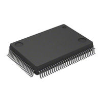
Renesas M16C/60 Series Hardware Manual (342 pages)
Brand:
Renesas
| Category:
Computer Hardware
| Size: 2.75 MB
Table of Contents
Table of Contents
5
How to Use this Manual
3
Quick Reference to Pages Classified by Address
9
Overview
15
Applications
15
Performance Outline
16
Block Diagram
17
Product List
18
Pin Configuration
19
Pin Description
20
Memory
22
Central Processing Unit (CPU)
23
Data Registers (R0, R1, R2, and R3)
23
Address Registers (A0 and A1)
23
Frame Base Register (FB)
24
Interrupt Table Register (INTB)
24
Program Counter (PC)
24
User Stack Pointer (USP), Interrupt Stack Pointer (ISP)
24
Static Base Register (SB)
24
Flag Register (FLG)
24
Sfr
25
Reset
37
Hardware Reset
37
Software Reset
37
Watchdog Timer Reset
37
Oscillation Stop Detection Reset
37
Processor Mode
40
Types of Processor Mode
40
Setting Processor Modes
40
Bus
45
Bus Mode
45
Bus Control
46
Address Bus
46
Data Bus
46
Chip Select Signal
46
Read and Write Signals
48
ALE Signal
48
The RDY Signal
49
HOLD Signal
50
BCLK Output
50
External Bus Status When Internal Area Accessed
52
Software Wait
52
Clock Generation Circuit
56
Main Clock
64
Sub Clock
65
Ring Oscillator Clock
66
PLL Clock
66
CPU Clock and Peripheral Function Clock
68
CPU Clock and BCLK
68
F 2 , F 8 , F 32 , F 1SIO , F 2SIO , F 8SIO , F 32SIO , F AD , F CAN0 , F C32 )
68
Clock Output Function
68
Power Control
69
Normal Operation Mode
69
Wait Mode
71
Stop Mode
73
Normal Mode
75
Oscillation Stop and Re-Oscillation Detection Function
78
Protection
80
Interrupts
81
Type of Interrupts
81
Software Interrupts
82
Hardware Interrupts
83
Interrupts and Interrupt Vector
84
Interrupt Control
86
Interrupt Sequence
89
Interrupt Response Time
90
Interrupt Priority
92
INT Interrupt
94
Key Input Interrupt
96
CAN0 Wake-Up Interrupt
96
NMI Interrupt
96
Address Match Interrupt
97
Watchdog Timer
99
Dmac
101
Transfer Cycle
106
DMA Transfer Cycles
108
DMA Enable
109
DMA Request
109
Channel Priority and DMA Transfer Timing
110
Timers
111
Timer a
113
Timer Mode
117
Event Counter Mode
118
One-Shot Timer Mode
123
Pulse Width Modulation (PWM) Mode
125
Timer B
128
Timer Mode
131
Event Counter Mode
132
Pulse Period and Pulse Width Measurement Mode
133
Three-Phase Motor Control Timer Function
136
Serial I/O
147
Uarti (I = 0 to 2)
147
Clock Synchronous Serial I/O Mode
156
Clock Asynchronous Serial I/O (UART) Mode
163
Special Mode 2
170
Special Mode 3 (IE Mode)
184
Special Mode 4 (SIM Mode) (UART2)
186
Si/O3
191
A-D Converter
196
One-Shot Mode
200
Repeat Mode
202
Single Sweep Mode
204
Repeat Sweep Mode 0
206
Repeat Sweep Mode 1
208
D-A Converter
212
CRC Calculation
214
CAN Module
216
CAN Module-Related Registers
217
CAN0 Message Box
218
Acceptance Mask Registers
220
CAN SFR Registers
221
Operational Modes
230
Configuration of the CAN Module System Clock
232
CAN Bus Timing Control
232
Acceptance Filtering Function and Masking Function
234
Acceptance Filter Support Unit (ASU)
235
Basic CAN Mode
236
Return from Bus off Function
237
Time Stamp Counter and Time Stamp Function
237
Listen-Only Mode
237
Reception and Transmission
238
CAN Interrupts
241
Programmable I/O Ports
242
Port Pi Direction Register (Pdi Register, I = 0 to 10)
242
Port Pi Register (Pi Register, I = 0 to 10)
242
Pull-Up Control Register J (Purj Register, J = 0 to 2)
242
Port Control Register (PCR Register)
242
Electrical Characteristics
254
Read Timing
266
Write Timing
266
Flash Memory
272
Flash Memory Performance
272
Memory Map
273
Boot Mode
274
Functions to Prevent Flash Memory from Rewriting
274
CPU Rewrite Mode
276
Software Commands
284
Status Register
289
Standard Serial I/O Mode
293
Parallel I/O Mode
297
CAN I/O Mode
298
Electrical Characteristics
301
Advertisement
Advertisement
Related Products
Renesas M16C/64
Renesas M16C/6NK
Renesas M16C/6N
Renesas M16C/6NN
Renesas M16C/6N4
Renesas M16C/6V
Renesas M16C/62P Group
Renesas M16C/62PT
Renesas M16C/62P Series
Renesas M16C/64C
Renesas Categories
Computer Hardware
Motherboard
Microcontrollers
Adapter
Switch
More Renesas Manuals
Login
Sign In
OR
Sign in with Facebook
Sign in with Google
Upload manual
Upload from disk
Upload from URL