Leica GR10 Operational Manual
Hide thumbs
Also See for GR10:
- User manual (96 pages) ,
- Operational manual (317 pages) ,
- User manual (20 pages)
Table of Contents
Advertisement
Quick Links
Advertisement
Table of Contents

Subscribe to Our Youtube Channel
Related Manuals for Leica GR10


Summary of Contents for Leica GR10
- Page 1 Leica GR10/GR25 Operational Manual (Online Help)
-
Page 3: Table Of Contents
Table of Contents 1: Introduction ................................... 12 How to use the Online Help: Overview ..........................12 How to display and use the Online Help ..........................13 How to find a online help topic ............................... 14 How to print a online help topic ............................. 15 Available documentation ............................... - Page 4 Use a hostname to access an instrument with a static IP address ..................89 Access the web interface for the first time and change the default user ................. 90 Activate Leica support access step-by-step ........................... 91 Configure coordinates and site name step-by-step ........................ 92 Configure tracking settings step-by-step ..........................
- Page 5 1: Introduction Outgoing data stream wizard: Connection ........................... 155 Outgoing data stream wizard: Configure TCP/IP server ...................... 156 Outgoing data stream wizard: Configure TCP/IP client ......................157 Outgoing data stream wizard: Configure Ntrip server (source) .................... 158 Outgoing data stream wizard: Configure Serial port ......................160 Outgoing data stream wizard: Configure Radio ........................
- Page 6 Software: Overview ................................293 Is my firmware up to date? ..............................295 Firmware upgrade step-by-step ............................296 Firmware upgrade using Leica GNSS Spider ........................300 Loading a Language file ..............................301 8: GNSS Spider / Remote Access ............................303 GNSS Spider / Remote Access: Overview .......................... 303 GNNS Spider / Remote Access ............................
- Page 7 10. Support resources ................................331 Support resources ................................331 11: External Devices ................................333 External Devices: Overview..............................333 Leica surveying controllers CS10/CS15 ..........................335 Working with Radio, Modem and GSM Devices: Overview ....................336 Serial Devices ..................................337 Slot-in Devices ..................................340 Configure a meteo device step-by-step ..........................
- Page 8 GPS (System) Time ................................426 GSM ....................................427 HATANAKA..................................428 HTTP ....................................429 HTTPS ....................................430 LB2 ..................................... 431 Leica 4G ..................................... 432 Leica format ..................................433 LLI....................................... 434 MDB ....................................435 NMEA-0183 ..................................436 Ntrip ....................................437 Real time message satellite signal support .......................... 439 RINEX ....................................
- Page 9 1: Introduction Signal-to-noise ratio (SNR) ..............................443 SMTP ....................................444 SSID ....................................445 Time Zone ................................... 446 UTC (Coordinated Universal Time) ............................. 447 UT1 ..................................... 448 WGS84 ....................................449 Wide Area Augmentation System (WAAS) .......................... 450 World Geodetic System 1984 (WGS 84) ..........................451 WPA / WPA2 ..................................
- Page 10 50, 117 ................................453 F ......................................453 Firmware 19, 276, 287 ..............................453 Firmware upgrade 276, 290 ............................453 Firmware upgrade using Leica GNSS Spider 294......................454 Is my firmware up to date? 289 ............................454 Format SD card 274, 314 ............................... 454 Format the receiver settings 32, 274, 314, 342, 343 ......................
- Page 11 1: Introduction L ......................................454 Language file 280, 295 ............................... 454 LED's GR10 30 ................................454 LED's serial devices 331 ..............................454 LED's slot-in devices 334 ..............................454 Leica Active Assist 286..............................454 Leica support user 86, 226 ............................. 454 Licenses 25, 95, 278 ..............................
- Page 12 Operational Manual (Online Help) Power down 274 ................................455 Reboot 274 ................................. 455 Reset settings 274 ............................... 455 Store settings 281 ............................... 455 Reference position 96 ..............................455 RefWorX 19, 287 ................................455 Remote access 231, 298 ............................... 455 Reset receiver settings 274 .............................
- Page 13 1: Introduction Wake-up session 204, 207 ............................456 Web interface access 225, 226 ............................456 Web server 247 ................................456...
-
Page 14: 1: Introduction
Operational Manual (Online Help) 1: Introduction How to use the Online Help: Overview The GR/GM Series Online Help (Operational Manual) is comprehensive guide to the GR10/GR25/GM10 and its operation. The table below provides a brief description of each chapter: Chapter... -
Page 15: How To Display And Use The Online Help
1: Introduction How to display and use the Online Help Accessing the Online Help using the Web interface There are three ways to access the Online Help whilst using the Web interface Access Online Help Description Press the help menu to open the complete Online Help. Press to open content-sensitive help. -
Page 16: How To Find A Online Help Topic
Operational Manual (Online Help) How to find a online help topic • Click the Contents tab to browse through topics by category. • or click the Index tab to see an alphabetically ordered list of index entries: either type the word you're looking for or scroll through the list. -
Page 17: How To Print A Online Help Topic
1: Introduction How to print a online help topic Background information The entire GR/GM Series Operation Manual (Online Help) can be printed from the PDF version. To print an individual Online Help topic follow the steps listed below. How to Print step-by-step Internet Explorer Steps Description... -
Page 18: Available Documentation
Detailed list of equipment available for GNSS reference stations Reference Stations including hardware and software. Equipment List Monitoring Equipment Detailed list of equipment available for Monitoring solutions. List Refer to the following resources for all GR/GM Series documentation/software: • the Leica GR/GM Series DVD • https://myworld.leica-geosystems.com... -
Page 19: 2: Description Of The System
2: Description of the system Description of the system: Overview Menu option Description General Information A detailed list of GR/GM Series design features, special features and satellites tracked. GNSS Reference Station Components Details a typical reference station setup and the most common accessories that can be used with a GR/GM Series instrument. -
Page 20: General Information
• Supports high capacity storage up to 32 GB and intelligent Smart clean-up. • Multiple data output formats including Leica, Leica 4G, RTCM 2.x,3.x, LB2, BINEX, CMR, CMR+. • Modern, user friendly Web interface GUI, available in different languages. •... -
Page 21: Gnss Reference Station Components
GNSS Reference Station Components GNSS Reference Station Components Component overview The following diagram shows a typical reference station setup and the most common accessories that can be used with a GR10/GR25/GM10. Radio/GSM antenna Antenna bracket Antenna cable GFU housing including... -
Page 22: Minimum Setup Components
The following diagram shows the minimum components required to operate a GR/GM Series instrument. SD card* Antenna cable GNSS antenna Computer running Web interface or Leica GNSS Spider Ethernet or USB cable GR10/GR25/GM10 Power supply * The GR/GM Series receiver can be operated without the SD card but only data streaming will be possible. -
Page 23: Main Components
Leica GNSS Spider The reference station software including comprehensive receiver control and configuration, file download and firmware upload functions which support working with Leica GR/GM Series instruments. Supports connection to single or multiple reference instruments simultaneously. * The GR25 features a screen and buttons which can be used for initial instrument setup or minor configuration changes in the... -
Page 24: Unpacking The Instrument
Operational Manual (Online Help) Unpacking the instrument Delivery box for GR/GM Series The minimum items delivered with the GR/GM Series include: GR10/GR25/GM10 GR/GM Series User Manual Allen key (GR25 only) Accessories Additional equipment such as cables, antennas and power supply required for a complete reference station installation are delivered with the GR/GM Series when ordered. -
Page 25: Instrument Components: Gr/Gm10
2: Description of the system Instrument Components Instrument Components: GR/GM10 User interface USB and SD card cover Front rubber bumper Back rubber bumper GNSS Antenna port External Oscillator port Serial port (P1) Ruggedised Ethernet port Power port Communication Slot-in port Antenna (P3) Communication Slot-in port (P3) Related topics Ports &... -
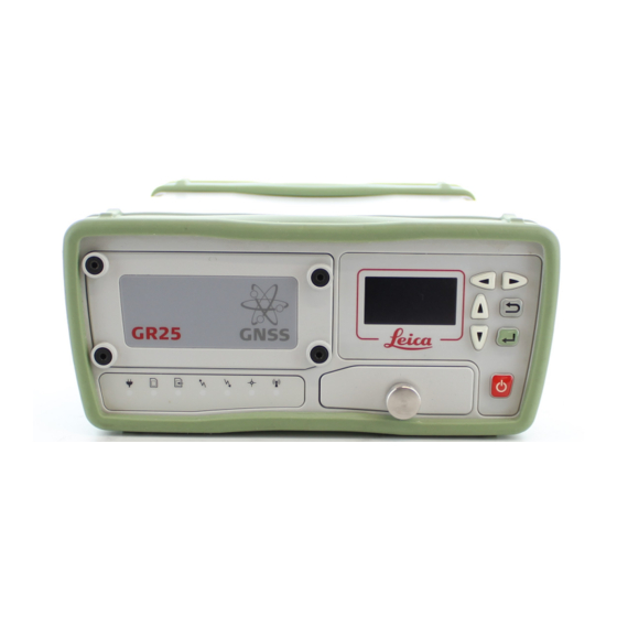
Page 26: Instrument Components Gr25
Operational Manual (Online Help) Instrument Components GR25 Battery cover LED's Front rubber bumper USB and SD card cover Display Buttons Back rubber bumper GNSS Antenna port Bluetooth or WLAN Antenna PPS port Serial and Event in port (P2) Serial port (P1) Ruggedised Ethernet port External Oscillator port Power port... -
Page 27: Operation
Leica Binary 2 (LB2) interface. Contact your Leica Geosystems representative for information on LB2 documentation. The GR10/GR25/GM10 is delivered with default settings which cover the needs of the typical user. Use the Web interface or Leica GNSS Spider to adjust the settings. - Page 28 Operational Manual (Online Help) Operation by Leica GNSS Spider The reference station software Leica GNSS Spider provides some of the same instrument operation functionality as the Web interface. Some configuration settings are available both in the Web Interface and in Leica GNSS Spider. If such settings are configured in the Web interface, and then an Upload Settings or Start is done from GNSS Spider, these will be overwritten.
-
Page 29: Software: Overview
Web interface. For detailed step-by-step instructions, refer to Firmware upgrade step-by- step. Leica GNSS Spider can also be used to install the firmware. Loading the firmware to the SD card and installing it on the instrument is done in one step when using GNSS Spider. Refer to the Leica GNSS Spider Online Help for more information. - Page 30 Operational Manual (Online Help) Related topics Is my firmware up to date? Firmware upgrade step-by-step Firmware upgrade using Leica GNSS Spider Loading a Language file Status: Receiver Information Receiver setup: Firmware management Receiver setup: Language management...
-
Page 31: Power Supply
External power supply: GEV242 (774437), 110 V/240 V AC to 24 V DC power supply unit, supplied by Leica Geosystems. GEV251 (722409), 110 V/240 V AC to 12 V DC power supply unit, supplied by Leica Geosystems GEB171 (439038) battery connected via a cable. -
Page 33: 3: Installation
3: Installation Installation: Overview Menu option Description Before Installation A detailed list of things to consider before installing the instrument, including • Installation location • Installation orientation • Cable installation Installation options Detailed diagram of possible installations • Rack mount •... -
Page 34: Before Installation
Operational Manual (Online Help) Before Installation Installation location It is recommended that the instrument is installed so that it is • protected from mechanical influences and lightning. • within 70 m of the antenna, without the need to use inline amplifiers. •... -
Page 35: Installation Options
Radio/GSM antenna Antenna bracket Radio/GSM antenna cable Wall mount accessory - screws GR10/GR25/GM10 Rack accessory Wall mount accessory - bracket Wall / Cabinet Mount Together with the wall mount accessory kit the instrument can be easily mounted onto an existing wall or structure, or inside an environmental case. - Page 36 Operational Manual (Online Help) • The radio/GSM antenna must be installed on the outside of the rack if a slot-in radio or GSM device is used. Attach the Radio/GSM antenna cable to port P3. Radio/GSM antenna Antenna bracket Radio/GSM antenna cable Wall mount accessory - bracket Wall mount accessory - screws Rubber bumper...
- Page 37 3: Installation The instrument has a built-in Tripod mount to allow attachment to all Leica Geosystems Tripods. • When using the instrument on a tripod, the rubber bumpers must be on. AS10 GNSS antenna carrier with 5/8 inch screw Tribach...
-
Page 39: 4: User Interface
4: User Interface User Interface - Overview Menu option Description GR/GM10 LED Indicators on GR/GM10 A detailed overview of the LED indicators on the GR/GM10 and their status. Keyboard A detailed overview of the buttons on the GR/GM10 • ON/OFF button •... -
Page 40: Led Indicators On Gr/Gm10
Operational Manual (Online Help) GR/GM10 LED Indicators on GR/GM10 The GR/GM10 has Light Emitting Diode indicators. They indicate the basic instrument status. Power LED SD card LED Raw data logging LED RT out data stream LED RT in data stream LED Position LED Description of the LED's IF the... - Page 41 4: User Interface Active logging sessions are configured but the SD card is full or no satellites are tracked. Recommended user action: Check the SD card and the tracking status. RT out data No active real time out data stream or power is off. stream LED green One or more real time data streams are configured and active.
-
Page 42: Keyboard Gr/Gm10
Operational Manual (Online Help) Keyboard GR/GM10 Keyboard GR/GM10 ON/OFF button Function button LED's The instrument can be turned on and off by holding down the ON/OFF button for 2 s. A green steady light at the power LED indicates that the instrument is turned on and ready. ON/OFF button Button Function... - Page 43 4: User Interface If all logging sessions had been off, the Raw data logging LED is flashing green. • Press the Function button until the LED flashes quickly to START all configured logging sessions if the Raw data logging LED is flashing green. If any logging session had been active, the Raw data logging LED is flashing red.
- Page 44 Operational Manual (Online Help) • Use the buttons functionality as described above. • Press the Function button until all LEDs stop flashing.
-
Page 45: Usb And Sd Card Cover Gr/Gm10
While other SD cards can be used, Leica Geosystems recommends only using Leica SD cards. Leica Geosystems is not responsible for data loss or any other error that can occur while using a non-Leica card. SD cards can directly be used in the Leica USB Card Reader (767895 MCR7). Other computer card drivers can require an adaptor. -
Page 46: Led Indicators On Gr25
Operational Manual (Online Help) GR25 LED Indicators on GR25 The GR25 has Light Emitting Diode indicators. They indicate the basic instrument status. a. Power LED b. SD card LED c. Raw data logging LED d. RT out data stream LED e. - Page 47 Recommended user action: Check and reattach the battery. If the problem does not disappear, please send the battery to Leica Geosystems Service. Charging is only indicated via LEDs when the instrument is turned off. When the instrument is on, the LEDs indicate the current power level.
- Page 48 Operational Manual (Online Help) yellow Active logging sessions are configured and Smart clean-up is deleting data from all or some of the configured logging sessions. Active logging sessions are configured but no position is available. Recommended user action: Check the remaining space of the SD card and delete old data if necessary.
-
Page 49: Keyboard: Gr25
4: User Interface Keyboard: GR25 Left button Right button Up button Cancel button Down button Enter button Display ON/OFF button The instrument can be turned on and off by holding down the ON/OFF button for 3 s. A green steady light at the power LED indicates that the instrument is turned on and ready. -
Page 50: Display: Gr25
Operational Manual (Online Help) Display: GR25 Display menu structure The following functionality is available via the GR25 display. Main Menu ¦ ¦--- Status ¦ ¦ ¦ ¦----------- Server Info Select to view receiver information. Use the up and down ¦ ¦... - Page 51 4: User Interface ¦----------- Site Config Select to edit site code, antenna type and antenna height. ¦ ¦------- Site code ¦ ¦------- Antenna type ¦ ¦------- Antenna height ¦ ¦----------- Logging sessions Select to activate or deactivate configured logging sessions. Use right and left buttons to activate or deactivate a ¦...
- Page 52 Operational Manual (Online Help) ¦------- Stop USB Device ¦------- Initialize ME How to navigate and edit settings in the Display I want to Description Open a page Use the up/down buttons to navigate to the menu item. Press the enter button to open the page.
- Page 53 4: User Interface Press OK to confirm or Cancel to abort. Edit a setting Step Description Navigate to the setting using the Enter button to open the page and the up/down buttons to select the setting. Press Enter to activate the edit mode. Note that the left most character is underlined.
- Page 54 Operational Manual (Online Help)
-
Page 55: Usb And Sd Card Cover: Gr25
It is recommended to switch off the instrument before removing the SD card. While other SD cards can be used, Leica recommends to only use Leica SD cards and is not responsible for data loss or any other error that can occur while using a non-Leica card. -
Page 56: Web Interface: Login
Operational Manual (Online Help) Web interface Web Interface: Login Entering the receivers IP address or hostname in a browser window always displays the web interface login page. • For a partially restricted web interface access, the login as guest button can be used. This login allows access to all Status information. -
Page 57: Web Interface: User Interface
Left of the status block is the content area. This contains the actual information for this page, e.g. status information, a configuration page or links to receive support and information directly from Leica Geosystems AG. Update rates for each element in the status block is as follows: Event log: 5s, Tracking block: 10s, General block: 15s. -
Page 58: Menu Bar
Send receiver information and questions to your Leica support contact, stay informed about Support new firmware releases or browse the Leica FAQs to quickly find a solution for common questions. Logout Select to logout of the web interface and return to the main login page. - Page 59 4: User Interface Recommended user action: The user should urgently switch to a new battery or enable charging. Power status The power status is shown with an icon and the current voltage level. The primary power supply is in use and that the power level is valid (voltage is between the configured power up and power down level).
- Page 60 Operational Manual (Online Help) Recommended user action: Exchange the external USB drive. The external USB drive is full. Data logging is continued until the SD card is full. The external USB drive is configured to be used but currently not detected. Recommended user action: Immediately exchange the external USB drive or detach and reattach the USB drive.
- Page 61 4: User Interface The Tracking box provides an overview of the current tracking status of the receiver. • All satellite systems are listed, independent of the installed option keys. For further information on option keys go to Tools / Options. •...
- Page 62 Operational Manual (Online Help) Number of QZSS satellites available above the cut-off angle. QZSS Sat. available tracking can only be activated when the QZSS option is installed on the receiver. Tracked L1 Tracked QZSS satellites on L1. Tracked L2C Tracked QZSS satellites on L2C. Tracked L5 Tracked QZSS satellites on L5.
- Page 63 4: User Interface No time signal is available from the configured external oscillator. If no position is available either, no time signal is available to the receiver. If a position is available, the receiver has not received a time signal from the external oscillator for more than 5min and an automatic fallback to the internal oscillator has occurred.
-
Page 64: Tool Tips
Operational Manual (Online Help) The underlined SD Card token in the Logging session properties pop-up box opens an FTP access to the receivers SD card. A pop-up box is also opened when clicking on the number of tracked satellites in the Tracking status block. Press the button in the upper right corner to close the pop-up box. - Page 65 4: User Interface Move the mouse away from the icon and the tool tip disappears. Related topics LED Indicators on GR/GM10 LED Indicators on GR25...
-
Page 67: 5: Getting Started
Use DynDNS to assign a hostname to a GR/GM Series with a static IP • Access the web interface for the first time and change the default user • Activate Leica support access step-by-step • Configure coordinates and site name step-by-step •... -
Page 68: Network Technology And Protocol Overview
Operational Manual (Online Help) Network technology and protocol overview This section explains some of the networking technologies and protocols which are used by the receiver. DNS stands for “Domain Name System”. This protocol allows the usage of a hostname rather than only using the IP address to register and access a network device within a computer network. -
Page 69: Basic Setup Step-By-Step
Step Description Find the power port (PWR) at the back of the GR10/GR25/GM10. Plug the power cable/GEV238 power supply into the GR10/GR25/GM10. Insert the SD card into the SD card slot. For more information on how to work with the SD card, refer to Working with the Memory Device. -
Page 70: Setup Via Web Interface Over Ethernet And Dhcp
Operational Manual (Online Help) Setup via Web Interface over Ethernet and DHCP Setup via Web Interface over Ethernet and DHCP GR10/GR25/GM10 Local network (LAN) DHCP server Ethernet cable Computers with Web interface Step Description Start the computer. To connect the instrument to the local LAN supporting DHCP, plug an Ethernet cable with a RJ45 connector into the RJ45 Ethernet port on the back of the instrument. -
Page 71: Setup In A Non-Dhcp Network
Connect the crossed Ethernet cable to the computer and the Ethernet port on the back of the GR10/GR25/GM10. Turn on the GR10/GR25/GM10. On the computer go Start / Control Panel / Network Connections. Select the Network connection used with the crossed Ethernet cable, right click and select Properties. - Page 72 Operational Manual (Online Help) Press OK. Open a browser window and enter 192.168.0.3 to open the Web interface. Per default, the instrument is configured to obtain an IP address automatically from a DHCP network. To use the default static IP address 192.168.0.3, reboot the instrument once it is connected to the crossed Ethernet cable.
-
Page 73: Gr25 Setup In A Non-Dhcp Network Using Screen And Buttons
5: Getting started GR25 setup in a non-DHCP network using screen and buttons In a field campaign the GR25 can be configured through the screen and buttons, to start or stop pre-configured data streams and logging sessions. For initial setup, the GR25 IT configuration for setup in a non-DHCP network can be done through the screen and buttons. Left button Right button Up button... -
Page 74: Install Usb Drivers
Operational Manual (Online Help) Install USB drivers Install USB drivers Before connecting the GR10/GR25/GM10 to a computer using a USB cable, you must first install USB drivers. To install the USB drivers refer to: • Install USB drivers for Windows XP operating systems •... -
Page 75: Install Usb Drivers For Windows Xp Operating Systems
64 bit CPU: SetupViva&GR_USB_64bit.exe • Itanium 64 bit CPU: SetupViva&GR_USB_64bit_itanium.exe The Welcome to the InstallShield Wizard for Leica Viva & GR USB drivers window appears. Make sure that all GR/GM or Viva devices are disconnected from the PC. Click Next>. - Page 76 Operational Manual (Online Help) A DOS window is opened and a batch file is started to configure the IP settings for the RNDIS network adapter. Press any key to close the DOS window. Disconnect and reconnect the USB cable. Open a browser and type in the IP address: 192.168.254.2 to access the Web interface. Configure the instrument for all required settings.
-
Page 77: Install Usb Drivers For Windows Vista Operating Systems
Click OK. Restart the computer for all changes to take effect. (Not needed if UAC is already disabled). Insert the Leica GR/GM Series DVD. Run the installer executable depending on your CPU and operating system to install the drivers necessary for your GR10/GR25/GM10. - Page 78 Operational Manual (Online Help) After logging in the first time you must create a new user account, including a new user name and password. The default user account can then be deleted. Go to Access the web interface for the first time and change the default user for a step-by-step guide.
-
Page 79: Install Usb Drivers For Windows 7 Operating Systems
Itanium 64 bit CPU: SetupViva&GR_USB_64bit_itanium.exe Wait until the Mobile Device Center Driver Update is finished. The Welcome to the InstallShield Wizard for Leica Viva & GR/GM USB drivers window appears. Click Next>. The Ready to Install the Program window appears. - Page 80 Operational Manual (Online Help) After logging in the first time you must create a new user account, including a new user name and password. The default user account can then be deleted. Go to Access the web interface for the first time and change the default user for a step-by-step guide.
-
Page 81: Setup Via Web Interface Over Usb
5: Getting started Setup via Web Interface over USB Step Description Turn on the instrument. Start the computer. Loosen the screw on the SD card/USB port cover. Open the SD card/USB port cover. Plug the USB cable into the USB port on the instrument. Plug the USB cable into the USB port of the computer. -
Page 82: Troubleshooting: Installing Usb Drivers
Operational Manual (Online Help) Troubleshooting: Installing USB drivers The Web interface is not available Have you Followed the steps outlined in Setup via Web Interface over USB, for the first time ? If the web interface is not available it might be necessary to manually assign an IP address to the virtual network adapter. -
Page 83: Setup Via Web Interface Over Bluetooth
5: Getting started Setup via Web Interface over Bluetooth or WLAN (GR25) Setup via Web Interface over Bluetooth Only available for GR25 with bluetooth radio installed. Left button Right button Up button Cancel button Down button Enter button Screen ON/OFF button Step Description Turn on the GR25. -
Page 84: Setup Via Web Interface Over Wlan (Gr25)
Operational Manual (Online Help) Setup via Web interface over WLAN (GR25) Only available for GR25 with WLAN radio installed. Please note that this page describes a wireless ad-hoc connection to the default profile. For user defined ad- hoc setups, please edit the described settings accordingly. Left button Right button Up button... -
Page 85: Batteries Operating Principles
• For Li-Ion batteries, a single discharging and charging cycle is sufficient. We recommend carrying out the process when the battery capacity indicated on the charger or on a Leica Geosystems product deviates significantly from the actual battery capacity available. -
Page 86: Charging The Gr25 Battery
Operational Manual (Online Help) Charging the GR25 battery Insert and remove the battery on the GR25 step-by-step Step Description The battery is inserted in the front of the instrument. Loosen the screws on the battery compartment with the Allen key provided with the GR25. Remove the battery cover. -
Page 87: Using The Gr25 Internal Battery And Charger
5: Getting started Using the GR25 Internal Battery and Charger Charging • Battery charging can be enabled in the GR25 Web Interface. Go to Receiver setup / Power management. Note: When charging the GEB241 battery with the GR25 internal charger, it is technically possible to charge the GEB241 battery between 0°C to +65°C/ +32°F to +149°F. -
Page 88: Working With The Memory Device
Operational Manual (Online Help) Working with the Memory Device Working with the Memory Device • Keep the card dry. • Use it only within the specified temperature range. • Do not bend the card. • Protect the card from direct impacts. •... -
Page 89: Insert And Remove An Sd Card Into The Instrument Step-By-Step
5: Getting started Insert and remove an SD card into the instrument step-by-step Step Description The SD card is inserted into a slot inside the SD card/USB port cover on the front of the instrument. Loosen the screw on the SD card/USB port cover. Open the SD card/USB port cover. -
Page 90: Use Dhcp To Automatically Assign An Ip Address And All Network Parameters To An Instrument
Operational Manual (Online Help) Use DHCP to automatically assign an IP address and all network parameters to an instrument This procedure requires DHCP and DNS servers within the network the GR/GM receiver is connected to. As a result all network parameters will be assigned automatically. -
Page 91: Use A Hostname To Access An Instrument With A Static Ip Address
5: Getting started Use a hostname to access an instrument with a static IP address This procedure requires a DNS server in the network the GR/GM Series is connected to. As a result the assigned hostname can be used to access the receiver within the network. If no DHCP server is available all network parameters have to be entered manually. -
Page 92: Access The Web Interface For The First Time And Change The Default User
Operational Manual (Online Help) Access the web interface for the first time and change the default user This section explains using which user account the web interface can be accessed for the first time, how a new user account is created and how the default user account is deleted. -
Page 93: Activate Leica Support Access Step-By-Step
5: Getting started Activate Leica support access step-by-step This section explains how Leica Support can be allowed to access the web interface. Step Description Enter the web interface using a user account having Administrator rights. Go to Support / Properties. -
Page 94: Configure Coordinates And Site Name Step-By-Step
Operational Manual (Online Help) Configure coordinates and site name step-by-step This section explains how to configure site coordinates and site name Step Description Access the web interface. Go to page GNSS management / Site name and coordinates. Enter values in the text field Site code. This four character ID will be used as identifier for the instrument and will be used for the name of logged files (first four characters of the file name). -
Page 95: Configure Tracking Settings Step-By-Step
5: Getting started Configure tracking settings step-by-step This section explains how to configure the tracking settings. Step Description Access the web interface. Go to page GNSS management / Tracking. On the General tab the basic tracking options can be configured. Select the satellite systems you want to track using the check boxes. -
Page 96: Configure A Rinex Logging Session Step-By-Step
Operational Manual (Online Help) Configure a RINEX logging session step-by-step This section explains how to configure a continuous RINEX logging session. Step Description Access the web interface. Go to page GNSS management / Logging sessions. Use the button Create a new logging session The logging session wizard will start. -
Page 97: Configure A Data Stream Step-By-Step
5: Getting started Configure a data stream step-by-step This section explains how to configure a new outgoing real time data stream using a radio. Step Description Access the web interface. Go to page GNSS management / Data streams. Use the button Create a new data stream The outgoing data stream wizard will start. -
Page 99: 6: Context Sensitive Help
Or use the tools to upgrade the receiver firmware, add new option keys or switch to your preferred language. Support The Support menu options allow you to send the settings of your receiver and debug information to Leica NRS support in order to help solve receiver problems. -
Page 100: Status: Overview
Operational Manual (Online Help) Status Status: Overview View the status of important receiver information, such as the configured logging sessions, the satellite tracking, an overview of the ports in use and the power and memory available. Menu option Description Receiver information View detailed information about the receiver, including the installed firmware version, maintenance date and options. -
Page 101: Status: Receiver Information - Receiver
Default functionality Description Ethernet Ethernet connection is available on every GR/GM Series receiver. GNSS Spider OWI The Leica GNSS Spider software can connect and control any GR/GM Series receiver per default. No additional option is needed. Loaded firmware Description Maintenance end The expiry date of the software maintenance contract. - Page 102 Operational Manual (Online Help) activate or deactivate the Automatic status page reload. Related topics Status: Overview Status: Receiver information - Options GNSS management Receiver setup...
-
Page 103: Status: Receiver Information - Options
6: Context sensitive help Status: Receiver information - Options Background information The receiver options tab lists all the options available for this receiver and which of these options are already installed. • To install new options go to Receiver setup / Tools / Options. •... -
Page 104: Status: Position
Operational Manual (Online Help) Status: Position Background Information Shows the currently calculated position and the user entered reference position of the receiver. The receiver's position is configured via GNSS Management / Site name and coordinates. • If the entered reference position and currently calculated position differ by more than 100 m, an error message is displayed. - Page 105 6: Context sensitive help Local time The current time in the local time system. Daylight saving time is not accounted for. Position The latency of the computed position. latency Latency is typically attributed to the time required for data transfer and computation of position. HDOP The Horizontal Dilution of Precision (HDOP) of the current position solution.
-
Page 106: Status Tracking: General
Operational Manual (Online Help) Status: Tracking Status tracking: General Field Description The table below describes the fields in the Status: General tab. The information shown is dependent on the settings configured on the GNSS management: Tracking page and which satellite options are available on the receiver. If the satellite health setting has been changed to a user defined setting in the GNSS management: Tracking page, then the satellite PRN will be displayed in brackets to indicate that this is not the almanac transmitted health status for that satellite. - Page 107 6: Context sensitive help Related topics Tracking: GPS Tracking: GLONASS Tracking: GALILEO Tracking: SBAS Tracking: BEIDOU Tracking: QZSS GNSS management: Tracking...
-
Page 108: Status Tracking: Gps
Operational Manual (Online Help) Status tracking: GPS Field Description The table below describes the fields in the Status: GPS tab. The information shown is dependent on the settings configured on the GNSS management: Tracking page and which satellite options are available on the receiver. Press the Refresh icon to update the displayed data. -
Page 109: Status Tracking: Glonass
6: Context sensitive help Status tracking: GLONASS Field Description The table below describes the fields in the Status: GLONASS tab. The information shown is dependent on the settings configured on the GNSS management: Tracking page and which satellite options are available on the receiver. Press the Refresh icon to update the displayed data. -
Page 110: Status Tracking: Galileo
Operational Manual (Online Help) Status tracking: GALILEO Field Description The table below describes the fields in the Status: GALILEO tab. The information shown is dependent on the settings configured on the GNSS management: Tracking page and which satellite options are available on the receiver. Press the Refresh icon to update the displayed data. -
Page 111: Status Tracking: Sbas
6: Context sensitive help Status tracking: SBAS Field Description The table below describes the fields in the Status: SBAS tab. The information shown is dependent on the settings configured on the GNSS management: Tracking page and which satellite options are available on the receiver. Press the Refresh icon to update the displayed data. -
Page 112: Status Tracking: Beidou
Operational Manual (Online Help) Status tracking: BEIDOU Field Description The table below describes the fields in the Status: BEIDOU tab. The information shown is dependent on the settings configured on the GNSS management: Tracking page and which satellite options are available on the receiver. Press the Refresh icon to update the displayed data. -
Page 113: Status Tracking: Qzss
6: Context sensitive help Status tracking: QZSS Field Description The table below describes the fields in the Status: QZSS tab. The information shown is dependent on the settings configured on the GNSS management: Tracking page and which satellite options are available on the receiver. Press the Refresh icon to update the displayed data. -
Page 114: Status: Sky Plot
Operational Manual (Online Help) Status: Sky plot Background Information The sky plot shows which satellites are currently available and which ones are tracked. Satellites that are available but not tracked, e.g. due to obstructions, are shown in grey. Clicking onto a satellite icon or the PRN number will open a text box showing its: •... -
Page 115: Status: Data Streams - Outgoing
6: Context sensitive help Status: Data streams Status: Data streams - Outgoing Background information Displays a list of all configured Outgoing data streams from the receiver. Field Description The table below describes the fields in the Data streams / Outgoing tab. The information shown is dependent on the settings configured via the Data stream wizard on the GNSS management: Data streams / Outgoing tab page The data streams can be sorted by each field by clicking on the header. - Page 116 Operational Manual (Online Help) Connection: port The connection type and port over which the data stream is sent out. BINEX Description Icon Data stream is active. Data stream is inactive. Message The configured BINEX messages activated for the outgoing data stream. additional properties Click the listed BINEX messages to view BINEX message properties...
-
Page 117: Status: Data Streams - Incoming
6: Context sensitive help Status: Data streams - Incoming Background information Displays a list of all configured Incoming data streams from meteo and tilt devices that send data to the receiver. Field Description The table below describes the fields in the Data streams / Incoming tab. The information shown is dependent on the settings configured via the Data stream wizard on the GNSS management: Data streams / Incoming tab page. - Page 118 Operational Manual (Online Help) GNSS management: Data streams overview GNSS management: Incoming data streams Streaming session wizard: Configure Meteo Streaming session wizard: Configuration Tilt...
-
Page 119: Status: Logging Sessions
6: Context sensitive help Status: Logging sessions Background Information View status information about all configured logging sessions. Configure or edit a logging session via GNSS management / Logging sessions. A logging session wizard will guide you through the procedure. Field Description The table below describes the fields in the Status: Logging session page. - Page 120 Operational Manual (Online Help) Logging rate The configured rate at which the observations are logged. Length of file The configured file length. The file length defines how long data is written to one file before a new file is created. Log doppler Indicates if logging doppler observations is activated (yes) or deactivate (no) in the logging session.
-
Page 121: Status: Ntrip Caster
6: Context sensitive help Status: Ntrip caster Background Information Shows all the mount points configured on the local Ntrip caster. For each mount point the connection status and the connected source and clients are displayed. Field description The table below describes the fields on the Status: Ntrip caster page. Press the Refresh icon to update the displayed information. -
Page 122: Status: Port Summary
Operational Manual (Online Help) Status: Port Summary Background Information Shows all ports used in the receiver configuration for data streams, remote access (OWI), FTP and web interface access. For each port the connection status and use case is displayed. Field Description The table below describes the fields on the Status: Port summary page. - Page 123 6: Context sensitive help Disconnected Awaiting connection(s) Connected Port type Shows if HTTP or HTTPS is active and differentiates between FTP data ports and FTP control points. Port number The configured port number. To enable or disable the automatic update of the status page, please go to Receiver setup: Web server and activate or deactivate the Automatic status page reload.
-
Page 124: Status: Antenna
Operational Manual (Online Help) Status: Antenna Background information This page displays the currently configured antenna for this site. Field Description The table below describes the fields in the Status: Antenna page. The information shown is dependent on the antenna selected in GNSS management: Antenna management on the Select antenna tab. -
Page 125: Status: Event Log
6: Context sensitive help Status: Event log Background Information The Event log contains a list of status and information messages produced by the receiver. The Event log is updated every 5 seconds. The messages from the Event log can be sent to an administrator via an event email. Sending event emails can be configured and activated via Receiver setup / Event log. - Page 126 Operational Manual (Online Help) Show verbose Activate or deactivate verbose messages. messages Verbose messages provide additional information about the receiver status that are not shown per default, in order to keep the event log clearer. Verbose mode will be deactivated after closing the browser, logging out of the receiver, or rebooting the receiver.
-
Page 127: Status: Network Connections
6: Context sensitive help Status: Network connections Background information Displays all active network connections used to connect the receiver to a network, including DynDNS setup if configured. Possible connections • Ethernet • Mobile Internet • WLAN • TCP/IP over USB •... - Page 128 Operational Manual (Online Help) Subnet mask The subnet mask for the connection. Gateway The gateway for the connection. DNS servers The IP addresses of the DNS servers that are used. Data sent The amount of data sent out from this connection. Data received The amount of data received by this connection.
- Page 129 6: Context sensitive help Data received The amount of data received by this connection. Device name States that this connection is established via the Bluetooth local area network. To enable or disable the automatic update of the status page, please go to Receiver setup: Web server and activate or deactivate the Automatic status page reload.
-
Page 130: Status: System Resources
Operational Manual (Online Help) Status: System resources Background information Shows the status of the connected power supply and the used/free space on the inserted SD card. When HTTPS mode is used in Internet Explorer, the graphs shown on the System resources page may not display correctly. - Page 131 6: Context sensitive help SD Card Description Total size The total storage space available on the SD card. Memory left The available storage space remaining on the SD card. External USB drive Description Total size The total storage space available on the external USB drive. Memory left The available storage space remaining on the external USB drive.
-
Page 132: Gnss Management: Overview
Operational Manual (Online Help) GNSS management GNSS management: Overview Configure all GNSS data related settings, such as logging sessions, data streams and the tracking settings. Or enter site specific information such as the site name, position and antenna details. Menu option Description Site name and coordinates Enter the site name and coordinates of the receiver. -
Page 133: Gnss Management: Site Name And Coordinates
6: Context sensitive help GNSS management: Site name and coordinates Background Information Site name and coordinates is used to enter the reference station information that will be used for real time correction messages and raw data logging. Changing the site name and/or coordinates interrupts logging and streaming. If any of these settings are changed when a logging session is active then the current files will be finalized and new file(s) will start to be logged. - Page 134 Operational Manual (Online Help) 0123456789 ABCDEFGHIJKLMNOPQRSTUVWXYZ abcdefghijklmnopqrstuvwxyz - _ . (hyphen, underscore, period and space are also allowed) Marker number Enter a marker number. • The marker number is used to occupy the equivalent entry in the RINEX header when creating RINEX files for this site. •...
- Page 135 6: Context sensitive help Related Topics Status: Position Configure coordinates and site name step-by-step...
-
Page 136: Gnss Management: Tracking General
Operational Manual (Online Help) GNSS management: Tracking GNSS management: Tracking General Background information If an external oscillator is selected but not connected, the receiver will not track any satellite signals. If an external oscillator is selected but not connected and the fallback option is activated, the internal clock will be used. - Page 137 6: Context sensitive help Test mode must be selected if the desired SBAS system is not yet fully operational. It is suggested that the Automatic setting is used. This ensures that the receiver automatically selects the SBAS system which is valid for the current position of the receiver.
- Page 138 Operational Manual (Online Help) Oscillator Description An external oscillator can be used to provide a better quality time signal to the receiver Oscillator than that of the receiver's internal clock. When using an external oscillator, the same external oscillator can be used for a number of receivers, so that each receiver is guaranteed to be tracking satellites using the same time signal.
- Page 139 6: Context sensitive help The restore default button fills all fields with the default values and stores these values. Pressing the save button is not necessary. When accepting the confirmation message, all settings on this page are overwritten with the default settings. This button redirects you to the Tools page where you can re-initialize the measurement Initialize measurement engine.
- Page 140 Operational Manual (Online Help) Clock type TCXO 1.0 e-21 1.0 e-20 1.0 e-20 OCXO 2.51 e-26 2.51 e-23 2.51 e-22 Rubidium 1.0 e-23 1.0 e-22 1.3 e-26 Cesium 2.0 e-20 7.0 e-23 4.0 e-29 Related topics GNSS management: Tracking GPS GNSS management: Tracking GLONASS GNSS management: Tracking GALILEO GNSS management: Tracking BEIDOU...
-
Page 141: Gnss Management: Tracking Gps
6: Context sensitive help GNSS management: Tracking GPS Background information Tracking GPS options, may be used to control which health settings are used for each GPS satellite tracked by the receiver. Setting Descriptions The table below describes the settings that can be configured on the Tracking GPS tab. Field Description Satellite health... -
Page 142: Gnss Management: Tracking Glonass
Operational Manual (Online Help) GNSS management: Tracking GLONASS Background information Tracking GLONASS options may be used to control which health settings are used for each GLONASS satellite tracked by the receiver. Setting Descriptions The table below describes the settings that can be configured on the Tracking GLONASS tab. Field Description Satellite health... -
Page 143: Gnss Management: Tracking Galileo
6: Context sensitive help GNSS management: Tracking GALILEO Background information Tracking Galileo options may be used to control which health settings are used for each Galileo satellite tracked by the receiver. While the Galileo satellite system is not yet fully operational, it is recommended to force the satellite health of all Galileo satellites to be tracked to healthy to overwrite the current "unhealthy"... - Page 144 Operational Manual (Online Help)
-
Page 145: Gnss Management:tracking Beidou
6: Context sensitive help GNSS management:Tracking BEIDOU Background information Tracking BeiDou options may be used to control which health settings are used for each BeiDou satellite tracked by the receiver. Setting Descriptions The table below describes the settings that can be configured on the Tracking BeiDou tab. Field Description Satellite health... -
Page 146: Gnss Management: Tracking Qzss
Operational Manual (Online Help) GNSS management: Tracking QZSS Background information Tracking QZSS options may be used to control which health settings are used for each QZSS satellite tracked by the receiver. Setting Descriptions The table below describes the settings that can be configured on the Tracking QZSS tab. Field Description Satellite health... -
Page 147: Gnss Management: Data Streams Overview
GNSS management: Data streams overview Description GNSS management: Outgoing data stream Configure outgoing real time, LB2 (Leica Binary), NMEA or BINEX messages from the receiver. GNSS management: Incoming data streams Configure incoming meteo and tilt data streams to the receiver. -
Page 148: Gnss Management: Outgoing Data Streams
Background Information This page provides an overview of the configured outgoing data streams. Configure outgoing real time, LB2 (Leica Binary), NMEA or BINEX messages from the receiver by pressing Create new data stream The maximum number of configured outgoing data streams is 22, 20 TCP/IP connections and 2 serial connection available. - Page 149 6: Context sensitive help • Streamed data types - real time, LB2 (Leica Binary), NMEA or BINEX • Message selection • Connection type and configuration • Activating the data stream After installing the dual frequency option, the configured data streams must be restarted to enable both L1 and L2 streams.
-
Page 150: Outgoing Data Stream Wizard: Select Data Stream
Operational Manual (Online Help) Outgoing data stream wizard: Select data stream Setting Descriptions The table below describes the settings that can be configured on the Select data stream page. Setting Description Data stream type Select the data stream type. • Real time •... -
Page 151: Outgoing Data Stream Wizard: Configure Real Time Out Data Stream
Description Leica The proprietary Leica real time data format supporting GPS and GLONASS. This is the best format to use when working exclusively with Leica Viva rovers or other Leica rover units. Leica 4G Leica proprietary RT format supporting GPS (including L5), GLONASS and Galileo. - Page 152 Operational Manual (Online Help) RTCM 3.x GPS/ RTCM standard for correction transmission including message types 1003 & GLO compact 1011. Higher efficiency than RTCM versions 2.x. Supports real time services with significantly reduced bandwidth. Additional messages sent:1006, 1008, 1013, 1033, 1230 (if Glonass is tracked).
- Page 153 6: Context sensitive help Time Activate or deactivate time slicing. slicing Select activate to delay the sending of the real time message. This is required when a real time message from different reference stations are sent on the same radio channel. No.
-
Page 154: Outgoing Data Stream Wizard: Configure Lb2 Data Stream
Operational Manual (Online Help) Outgoing data stream wizard: Configure LB2 data stream Background Information LB2 is the Leica proprietary binary protocol to interface with the receiver. An outgoing LB2 stream can contain measurement data and/or satellite data. Setting Descriptions The table below describes the settings that can be configured on the Configure LB2 data stream page. -
Page 155: Outgoing Data Stream Wizard: Configure Nmea Data Stream
6: Context sensitive help Outgoing data stream wizard: Configure NMEA data stream Setting Descriptions The table below describes the settings that can be configured on the Configure NMEA data stream page. Setting Description Message Activate or deactivate the NMEA message check boxes that are to be output. A detailed description of each NMEA message is contained in Appendix B: NMEA Messages. -
Page 156: Outgoing Data Stream Wizard: Configure Binex Data Stream
Operational Manual (Online Help) Outgoing data stream wizard: Configure BINEX data stream Background Information BINEX (Binary Exchange Format) is an exchange format for GNSS data defined by UNAVCO. You can find more information about BINEX at http://binex.unavco.org. The configuration wizard includes a check box table which enables and disables individual BINEX messages. -
Page 157: Outgoing Data Stream Wizard: Connection
6: Context sensitive help Outgoing data stream wizard: Connection Background Information Data can be streamed from the receiver using a variety of communication types. Setting Descriptions The table below describes the settings that can be configured on the Connection page. Setting Description Connection type... -
Page 158: Outgoing Data Stream Wizard: Configure Tcp/Ip Server
This setting is only available for receivers with the GRL115, Multi-Client and Ntrip Caster option key loaded. For all other receivers the number of users is fixed to 1. The option can be purchased from Leica Geosystems. Limit access range Select the range of IP addresses, which are authorized to access the receiver. -
Page 159: Outgoing Data Stream Wizard: Configure Tcp/Ip Client
6: Context sensitive help Outgoing data stream wizard: Configure TCP/IP client Background Information The TCP/IP client connection setting allows the receiver to act as a TCP client and send data out to a configured IP address and port. This way no port has to be opened in the firewall to allow clients to connect to the receiver. Furthermore since the data stream is now sent to a PC port, the number of connections to the data stream is not limited by the receiver. -
Page 160: Outgoing Data Stream Wizard: Configure Ntrip Server (Source)
Operational Manual (Online Help) Outgoing data stream wizard: Configure Ntrip server (source) Background Information This mode allows the receiver to act as Ntrip Server, and to provide data to an Ntrip Caster. In terms of TCP/IP, the Ntrip server mode is in fact a TCP client mode. As an Ntrip Server, the receiver connects to a caster and starts to stream data. - Page 161 6: Context sensitive help sure the data stream sent to the Ntrip caster has a rate higher than 15 s. If the connected Ntrip server (source) is a GR/GM receiver, it will continuously try to reconnect every 5 s. Related Topics Status: Ntrip caster Ntrip caster: Overview Ntrip caster: Caster tab...
-
Page 162: Outgoing Data Stream Wizard: Configure Serial Port
Operational Manual (Online Help) Outgoing data stream wizard: Configure Serial port Background Information This mode allows data to streamed out of the physical serial port. This page allows you to change the settings of the instrument's serial port. Do not select the connection type Serial Port if you have a radio/modem/phone connected to the physical serial port. -
Page 163: Outgoing Data Stream Wizard: Configure Radio
6: Context sensitive help Outgoing data stream wizard: Configure Radio Background Information This mode allows data to be transmitted with an attached Radio device. The receiver supports eight different types of radios including seven which attach to the physical serial port via a serial cable and one which attaches to the Slot in port (P3). Only the radios listed in the Receiver settings: Device Management page are supported. -
Page 164: Outgoing Data Stream Wizard: Configure Gsm / Modem / Cdma - Dial Up
Operational Manual (Online Help) Outgoing data stream wizard: Configure GSM / Modem / CDMA - dial up Background Information This mode allows data to be transmitted with an attached GSM, Modem or CDMA - dial up service device. There are a number of default devices defined in the Receiver settings: Device Management page. -
Page 165: Outgoing Data Stream Wizard: Set Streaming Status
6: Context sensitive help Outgoing data stream wizard: Set streaming status Setting Descriptions The table below describes the settings that can be configured on the Set streaming status page. Setting Description Activate data stream Deactivate the data stream if you do not want it to run immediately. Press to go back to the previous wizard step. -
Page 166: Gnss Management: Incoming Data Streams
Operational Manual (Online Help) GNSS management: Incoming data streams GNSS management: Incoming data streams Background Information This page provides an overview of the configured incoming data streams. Configure incoming meteo or tilt data or use an incoming real time data stream to monitor the receiver's position, Create a new incoming data stream by pressing Create new data stream The maximum number of meteo, tilt and real time data streams is one of each type. - Page 167 • Real time data stream: • Received data types - real time, meteo or tilt data • Message selection - RTCM2, RTCM3. Leica, Leica 4G or CMR/CMR+ • Connection type and configuration • Activating the data stream •...
-
Page 168: Incoming Data Stream Wizard: Select Data Stream
Operational Manual (Online Help) Incoming data stream wizard: Select data stream Setting Descriptions The table below describes the settings that can be configured on the Select data stream page. Setting Description Data stream Select the incoming data stream type. type •... -
Page 169: Incoming Data Stream Wizard: Configure Meteo
6: Context sensitive help Incoming data stream wizard: Configure Meteo Background Information Meteorological sensors are used for measuring air pressure, temperature and relative humidity. The data from the meteo sensor is logged together with the GPS raw observations into the MDB and RINEX files. If RINEX logging is active, an additional meteo RINEX file is created that contains the data from the meteo sensor. - Page 170 Operational Manual (Online Help) Communication setting Default setting Port name Serial Port (P1). Baud rate 4800 Parity Even Data bits Stop bit Flow control No handshake. The handshake used between the receiver and the tilt device. Vaisala WXT520 default communication settings Communication setting Default setting Port name...
-
Page 171: Incoming Data Stream Wizard: Configure Tilt
Background Information Tilt devices (such as the Leica NIVEL210) are used for measuring inclinations. The data from the tilt device is logged together with the GPS raw observations into MDB files. When logging RINEX files, the tilt data is written into a special auxiliary file. - Page 172 Operational Manual (Online Help) D-Series NS-XX/DMG2 default communication settings Communication setting Default setting Port name Serial Port (P1). Baud rate 9600 Parity Even Data bits Stop bit Flow control No handshake. The handshake used between the receiver and the tilt device. The D-Series tilt sensor must be configured to use 9600 Baud, otherwise the GR/GM receiver will not be able to connect to the tilt sensor.
-
Page 173: Incoming Data Stream Wizard: Configure Real Time In Data Stream
This page is used to configure the receiving of real time correction messages for RTK and DGPS positioning. Incoming real time streams can be used to calculate a fixed or DGPS position. The calculated position can be streamed via an NMEA data stream and external applications such as Leica SpiderQC or Leica GeoMoS can be used to monitor the antenna movement and automatically generate alarms in case predefined thresholds are exceeded. - Page 174 Message Type Description Leica Leica proprietary real time data format supporting GPS and GLONASS. This is the best format to use when working exclusively with Leica reference station units. Leica 4G Leica proprietary real time data format supporting GPS (including L5), GLONASS and Galileo.
- Page 175 6: Context sensitive help The reference sensor and the associated GLONASS inter frequency biases will be defined in the following way: User defined (as set in web interface) RTCM Message 1230 (if contained in the incoming real-time data stream) RTCM Message 1033 (if contained in the incoming real-time data stream) Automatic (compute biases based on the data contained in the incoming real-time data stream).
- Page 176 Operational Manual (Online Help) sends interpolated corrections (ionospheric and geometric) to the rover. This product is best suited to broadcast transmission. This product would be used whe you have an old rover that cannot support the MAX format. The end user can have information about error/correction sizes.
-
Page 177: Incoming Data Stream Wizard: Connection
6: Context sensitive help Incoming data stream wizard: Connection Background Information Data can be received by the receiver using a variety of communication types. Setting Descriptions The table below describes the settings that can be configured on the Connection page. Setting Description Connection type... -
Page 178: Incoming Data Stream Wizard: Configure Tcp/Ip Server
Operational Manual (Online Help) Incoming data stream wizard: Configure TCP/IP server Background Information The receiver works as a TCP server allowing TCP clients to connect to the receiver's ports and transmit the data streams to the GR/GM series receiver. Setting Descriptions The table below describes the settings that can be configured on the Configure TCP/IP server page. -
Page 179: Incoming Data Stream Wizard: Configure Tcp/Ip Client
6: Context sensitive help Incoming data stream wizard: Configure TCP/IP client Background Information The TCP/IP client connection setting allows the receiver to act as a TCP/IP client and connect to a configured IP address and port to receiver data. Setting Descriptions The table below describes the settings that can be configured on the Configure TCP/IP client page. -
Page 180: Incoming Data Stream Wizard: Configure Ntrip Client
Operational Manual (Online Help) Incoming data stream wizard: Configure Ntrip client Background Information This mode allows the receiver to act as an Ntrip client, connect to an Ntrip Caster and receiver correction data. Setting Descriptions The table below describes the settings that can be configured on the Configure Ntrip client page. Setting Description Ntrip caster address... - Page 181 6: Context sensitive help Ntrip...
-
Page 182: Incoming Data Stream Wizard: Configure Serial Port
Operational Manual (Online Help) Incoming data stream wizard: Configure Serial port Background Information This mode allows the receiver to receive data on a physical serial port. This page allows the user to change the settings on the instrument's serial port. Setting Descriptions The table below describes the settings that can be configured on the Configure serial port page. -
Page 183: Incoming Data Stream Wizard: Set Streaming Status
6: Context sensitive help Incoming data stream wizard: Set streaming status Background Information An incoming real time data stream can only be activated if GPS and GLO tracking of L2C signals is disabled. If you want to activate an incoming real time data stream make sure to first disable the tracking of GPS and GLO L2C signals. -
Page 184: Gnss Management: Logging Sessions Overview
Operational Manual (Online Help) GNSS management: Logging sessions GNSS management: Logging sessions overview Description GNSS management: Logging sessions Configure, create or edit a logging session. GNSS management: Smart clean-up Enable and disable the smart clean-up of logging session files on the receiver. -
Page 185: Gnss Management: Logging Sessions
• A logging session must be active in order to begin logging. • All files can be directly imported into Leica Geo Office (LGO). All MDB and RINEX files can also be downloaded via GNSS Spider. • If you wish to push the logging session data to an FTP server, an FTP location needs to be configured before starting the logging session wizard. - Page 186 Operational Manual (Online Help) Press to create a new logging session based on the settings of an existing Create new logging session (copy) logging session. Activate The logging session is deactivated. Press to activate. The logging session is activated. Press to deactivate. Press to open the Create new Logging session wizard.
- Page 187 6: Context sensitive help you experience problems while accessing files via FTP. Archive to FTP location Indicates if the logging session data is archived to an FTP location. Latest file The file name of the last file that this logging session was written to. For RINEX and Hatanaka logging sessions it will always list the observa-tion file name (*.10o).
-
Page 188: Gnss Management: Smart Clean-Up
Operational Manual (Online Help) GNSS management: Smart clean-up Background Information The SD card in the receiver can run full if the logging session data files are not removed (e.g. by FTP push or download). Smart clean-up ensures that the SD card will not run full, while preserving the data that has the highest priority to the user. Smart clean-up functionality differs from auto delete files. - Page 189 6: Context sensitive help Click here to view the Smart clean up flow chart Related topics GNSS management: Logging sessions...
-
Page 190: Logging Session Wizard: Create A New Logging Session / Edit A Logging Session
Selecting timed will open an additional wizard step, Session timing. Do not change a logging session created by Leica GNSS Spider into a timed logging session. Spider cannot configure timed logging sessions. - Page 191 6: Context sensitive help Press to cancel and return to GNSS management: Logging session. Related topics Logging sessions: Overview GNSS management: Logging sessions GNSS management: Smart clean-up...
-
Page 192: Logging Session Wizard: Session Timing
Operational Manual (Online Help) Logging session wizard: Session timing Background information Timed logging sessions consider the configured file length and the configured interval length. Example: If a timed logging session is configured to • Start logging at a certain date at 15:00h •... - Page 193 6: Context sensitive help Configure the time for the next session to start as the number of days, hours and minutes after the last session ended. Note: The gap between logging sessions only has an impact if it is repeated at least once.
-
Page 194: Logging Session Wizard: Mdb
Operational Manual (Online Help) Logging session wizard: MDB Setting Descriptions The table below describes the settings that can be configured on the MDB page. Setting Description Logging rate Select the rate at which the observations are to be logged. Note: a faster logging rate results in higher resource consumption on the receiver. Length of file Choose a value from 5 minutes to 24 hours. -
Page 195: Logging Session Wizard: Rinex
6: Context sensitive help Logging session wizard: RINEX Setting Descriptions The table below describes the settings that can be configured on the RINEX page. Setting Description Logging rate Select the rate at which the observations are to be logged. Note: A faster logging rate results in higher resource consumption on the receiver. Length of file Choose a value from 5 minutes to 24 hours. -
Page 196: Logging Session Wizard: Compact Rinex (Hatanaka)
Operational Manual (Online Help) Logging session wizard: Compact RINEX (Hatanaka) Setting Descriptions The table below describes the settings that can be configured on the Compact RINEX (Hatanaka) page. Setting Description Logging rate Select the rate at which the observations are to be logged. Note: A faster logging rate results in higher resource consumption on the receiver. -
Page 197: Logging Session Wizard: Data Handling
6: Context sensitive help Logging session wizard: Data handling Setting Descriptions The table below describes the settings that can be configured on the Data handling page. Setting Description Zip files Activate to ZIP the logging session files. Directory naming Select the directory naming convention. convention This is the folder structure that will be used on the SD card, on the FTP server (when FTP push is used) and on the external USB device (if USB push is used) to store the... -
Page 198: Logging Session Wizard: Set Logging Status
Operational Manual (Online Help) Logging session wizard: Set logging status Setting Descriptions The table below describes the settings that can be configured on the Set logging status page. Setting Description Activate session Deactivate the logging session if you do not want it to run immediately. Press to go back to the previous wizard step. -
Page 199: Gnss Management: Ftp Push
6: Context sensitive help GNSS management: FTP and USB locations GNSS management: FTP push Background Information FTP locations configuration allows the user to • Add new FTP locations • Edit and delete FTP locations • View information about existing FTP locations FTP locations are used to push data created by a logging session on the receiver to an external FTP server. - Page 200 Operational Manual (Online Help) link to test the settings. Files deleted from the queue will not be automatically pushed to the FTP server. Press to clear the queue of pending files to be pushed to an FTP location. This Clear deletes a backlog of files caused by for example, FTP server unavailability.
-
Page 201: Gnss Management: External Usb Drive
6: Context sensitive help GNSS management: External USB drive Background Information External USB drive configuration allows the user to • View the number of files queuing to be pushed to the external USB drive • Delete the queue of files to be pushed The external USB drive is used to push data created by a logging session on the receiver to an external USB drive. - Page 202 Operational Manual (Online Help) Please make sure the USB hard drive used with the GR25 complies with this specification. If a USB hard disk is used that does not comply with this specification, it is highly recommended to self-power the hard disk when used with the GR25 receiver.
-
Page 203: Gnss Management: New / Edit Ftp Location
6: Context sensitive help GNSS management: New / Edit FTP location Background Information Enter the necessary access information for pushing logged data from the GR/GM receivers SD card to an external FTP server. Setting Descriptions The table below describes the fields in the New / Edit FTP location page. Setting Description Name... -
Page 204: Gnss Management: Antenna Management Overview
Operational Manual (Online Help) GNSS management: Antenna management GNSS management: Antenna Management overview Description Select antenna Select an antenna and enter the height reading and measurement type. Antenna management Upload new antenna files, create new antennas and restore antenna default values. -
Page 205: Gnss Management: Select Antenna
6: Context sensitive help GNSS management: Select antenna Background information Select the antenna currently connected to the receiver and enter the height reading and measurement type. Correctly specifying the antenna and related information is critical for high accuracy positioning. Changing the antenna type and/or antenna height interrupts logging and streaming. If any of these settings are changed when a logging session is active, then the current files will be finalized and new file(s) will start to be logged. -
Page 206: Gnss Management: Antenna Management
Operational Manual (Online Help) GNSS management: Antenna management Background information Upload new antenna files, create new antennas and restore antenna default values. Field Descriptions The table below describes the fields in the Antenna management tab. Field Description Loadable antenna files The name of the antenna file. - Page 207 6: Context sensitive help File upload Create/Edit and Antenna GNSS management: Select antenna...
-
Page 208: Gnss Management: Create/Edit An Antenna
Operational Manual (Online Help) GNSS management: Create/Edit an Antenna Field Descriptions The table below describes the fields in the Create/Edit an Antenna tab. Field Description Name The antenna name. When editing an existing antenna, the antenna name cannot be changed. Horizontal offset Horizontal distance from the physical reference point (ARP) to the point on the antenna where the slope height reading is measured. -
Page 209: Gnss Management: Calculate The Antenna Height Reading
GNSS management: Calculate the antenna height reading The pictures below show examples for a standard setup of a Leica AT504/AT504 GG antenna on a pillar and a tripod. They also illustrate the antenna height reading values and give an example of what a permanent antenna setup could look like. -
Page 210: Receiver Setup: Pps And Event In
Operational Manual (Online Help) Receiver setup: PPS and Event In Background Information PPS stands for pulse per second. If configured, the receiver sends out an electric pulse at a specified interval time. This can be used e.g. to activate another device. The pulse is sent out via the dedicated PPS port. For further information go to Ports & Pins Assignments: GR25. -
Page 211: Gnss Management: Wake-Up Sessions
6: Context sensitive help GNSS management: Wake-up sessions GNSS management: Wake-up sessions Background Information GNSS management setup: Wake-up sessions allows the user to • Configure new wake-up sessions. • Edit and delete existing wake-up sessions. • View information about existing wake-up sessions. Wake-up sessions define a number of intervals for which the receiver is configured to run. - Page 212 Operational Manual (Online Help) • The receiver powers down 1-30 seconds after the configured time. Logging files may not be finalised before the receiver is powered down. These files will be finalized when the receiver boots the next time. • After the last interval of a wake-up session has ended, the receiver is powered down and stays off.
- Page 213 6: Context sensitive help No. of intervals The total number of repeats for the session. Time between intervals The time between power down of one interval and the power up of the next interval. Interval length The length of one wake-up interval. Related topics GNSS management: New/Edit wake-up session GNSS management / Site name and coordinates...
-
Page 214: Gnss Management: New/Edit Wake-Up Session
Operational Manual (Online Help) GNSS management: New/Edit wake-up session Setting Descriptions The table below describes the fields in the New/Edit wake-up session page. This page opens when creating a new Wake-up session with the Create new wake-up session button. Setting Description Name Enter a unique name for the wake-up session. -
Page 215: Receiver Setup: Overview
6: Context sensitive help Receiver setup Receiver Setup: Overview Configure all receiver related settings such as network connections, FTP push locations and the user management. Or use the tools to upgrade the receiver firmware, add new option keys or switch to your preferred language. Menu option Description •... -
Page 216: Network Connections: Overview
Operational Manual (Online Help) Network connections Network connections: Overview The Network connections pages allow defining the access to the receiver via different communication options. Tab option Description General Specify the receiver's hostname, define internet gateway priorities and activate backup communication. Ethernet Configure the Ethernet settings which will enable the receiver to be accessed via the internet. -
Page 217: Network Connections: General
6: Context sensitive help Network connections: General Background Information The general network connection page allows setting the receiver's hostname, specifying the gateway priorities and activating the backup communication. Setting Descriptions The table below describes the settings that can be configured on the General tab. Hostname Description Receiver hostname... - Page 218 Operational Manual (Online Help) When the order of the default gateway priorities is changed, an already established mobile internet connection will be re- initialized. Backup communication Description Enable Enable the backup communication to back up your primary gateway (as configured in the Priority list) with the secondary gateway. When activated, the communication backup functionality will check regularly if the data packages sent via the primary gateway reach their destination in the network.
-
Page 219: Network Connections: Ethernet
6: Context sensitive help Network connections: Ethernet Background Information Ethernet configuration enables the receiver to be accessed via the Internet when an Ethernet cable is connected. Setting Descriptions The table below describes the settings that can be configured on the Ethernet tab. IP settings Description Obtain an IP address automatically... - Page 220 Operational Manual (Online Help) Press to trigger a renewed IP address from the DHCP server. Renew DHCP lease This option is only available when the Obtain IP address automatically check box is active. Trouble-shooting If you are not able to connect to your receiver via ethernet, please try the following: •...
-
Page 221: Network Connections: Mobile Internet
6: Context sensitive help Network connections: Mobile Internet Background Information Configure mobile Internet access (e.g. via GPRS device) to the receiver. Setting Descriptions The table below describes the settings that can be configured on the Mobile Internet page. Configure device for Internet usage Description Device Select the device to be used to connect the receiver to the Internet. - Page 222 Operational Manual (Online Help) Receiver setup: Device Management: Overview How to set up a mobile Internet connection...
-
Page 223: Network Connections: Bluetooth
6: Context sensitive help Network connections: Bluetooth Background Information Use Bluetooth configuration to configure the Bluetooth device on the receiver. Bluetooth is available only on GR25 receivers with the bluetooth hardware option. Setting Descriptions The table below describes the settings that can be configured on the Bluetooth page. Configure device for Internet Description usage... -
Page 224: Network Connections: Wlan
Operational Manual (Online Help) Network connections: WLAN Background Information Use WLAN configuration to configure the WLAN device on the receiver, allowing receiver configuration, data transfer and communication with network devices. Or use the internet sharing functionality to connect attached devices to the internet. WLAN functionality can only be used on GR25 with the WLAN radio integrated and the GLR120 WLAN option installed. - Page 225 6: Context sensitive help • RSSI >= -57 => "Excellent" For ad hoc connections an RSSI value cannot be provided. Thus "Available" will be shown if connected. Press delete to permanently delete the WLAN profile. Delete Press to edit the WLAN profile settings. The Edit WLAN profile page will open. Edit WLAN profile The profile name cannot be edited.
-
Page 226: Network Connections: New / Edit Wlan Profile
Operational Manual (Online Help) Network connections: New / Edit WLAN profile Background Information Enter the necessary settings to define a wireless LAN profile, allowing a one-to-one connection with another network device (ad hoc) or connecting to a network of devices (infrastructure). Setting Descriptions The table below describes the settings that can be configured on the WLAN page. - Page 227 6: Context sensitive help For more information on how to access the web interface in a non- DHCP network, please refer to Setup in a non - DHCP network. IP address Enter the Internet protocol address of the receiver. This field can only be edited if the Obtain an IP address automatically field is disabled.
- Page 228 Operational Manual (Online Help) if you supply the wrong key you will be authenticated and connected, however, no data frames will be passed through the Access Point or WLAN ad hoc device. This can be a bit confusing from the users perspective as he sees that the client is connected but "nothing works".
-
Page 229: Receiver Setup: Residential Gateway
6: Context sensitive help Receiver Setup: Residential Gateway Background Information The Residential Gateway configuration enables the receiver to work as a gateway to the internet. This means that IT devices which are connected to the receiver via a TCP/IP connection can share the internet connection of the receiver. Setting Descriptions The table below describes the fields in the Residential gateway page. - Page 230 Operational Manual (Online Help) If the mobile internet device should be used as WAN interface, make sure to define the mobile internet device as default gateway. To do this, go to Receiver Setup > Network connections: General and move the mobile internet device to the top of the priority list.
-
Page 231: Access Management: Overview
6: Context sensitive help Access Management Access Management: Overview Access Management is used to control access to the receiver via the web interface and FTP. Tab option Description • User management View configured users • Create new users • Delete users •... -
Page 232: Access Management: User Management
Operational Manual (Online Help) Access Management: User management Background Information User management configuration allows the Administrator to • View configured users • Create new users • Delete users • Edit users details and password Setting Descriptions The table below describes the settings that can be configured on the User management tab. Field Description User... -
Page 233: Access Management: Access Settings
6: Context sensitive help Access Management: Access settings Background Information The access settings allow the Administrator to • configure the user access to the web interface • Access a link to the FTP server access restrictions page Setting Descriptions The table below describes the settings that can be configured on the Access settings tab. Field Description Access to Web interface is... - Page 234 Operational Manual (Online Help) • the selected Web interface user level: Administrator, GNSS manager, Status Viewer or None. The Web interface user level is configured via Receiver setup / Access Management: User management / Create New User or Edit User. Access to Menu Web interface user level...
-
Page 235: New User / Edit User
6: Context sensitive help New User / Edit User Setting Descriptions The table below describes the settings that can be configured on the New User / Edit User page. Field Description User name Enter a unique user name. • Maximum number of characters allowed is 20. •... - Page 236 Operational Manual (Online Help) all available settings Which web interface pages are visible to each user level is dependent on whether the selected Access to Web interface is: Unrestricted, Partially restricted or Fully restricted. Go to Receiver Setup / Access management / Access settings tab, to change this setting. The Web interface access description below provides a summary of which pages will be available for each user depending on the access level.
- Page 237 6: Context sensitive help Status with login with login with login no access Fully GNSS with login with login no access no access restricted management Receiver setup with login Limited access Change password no access only Support with login no access no access no access Related topics...
-
Page 238: Gnss Spider And Remote Access: Overview
The receiver must be connected directly to the Spider site server using the USB cable or the direct Bluetooth connection. • Use the default USB connection settings (IP address 192.168.254.2) to configure the site in Leica GNSS Spider. • Use the default Bluetooth connection setting (IP address 192.168.253.2) to configure the site in Leica GNSS Spider. - Page 239 6: Context sensitive help Press to create a new remote access configuration based on the existing configuration. Create new Spider and remote port (copy) Activate The remote access is deactivated. Click to activate the stream. The remote access is activated. Click to deactivate the stream. Create new Spider Click to open the Spider/remote access wizard.
-
Page 240: Remote Access Wizard: Connection
The table below describes the settings that can be configured on the Connection page. Setting Description Connection type Select the connection type that is needed for Leica GNSS Spider or other OWI based software to connect to the receiver. TCP/IP server This setting allows the receiver to works as a TCP server, allowing TCP clients to connect to the receiver's NET ports. -
Page 241: Remote Access Wizard: Configure Tcp/Ip Server
Setting Description TCP/IP port Enter the TCP/IP port of the receiver for Leica GNSS Spider or other OWI based software to connect to. Data receive time out If for a Spider / OWI connection no OWI requests are received within the specified time, the connection will be automatically reinitialized. -
Page 242: Remote Access Wizard: Configure Tcp/Ip Client
Operational Manual (Online Help) Remote access wizard: Configure TCP/IP client Background Information The TCP/IP client connection setting allows the receiver to act as a TCP client and connect to a configured IP address and port. This way no port has to be opened in the firewall on the receiver side to allow clients to connect to the receiver. Setting Descriptions The table below describes the settings that can be configured on the Configure TCP/IP client page. -
Page 243: Remote Access Wizard: Configure Ntrip Server (Source)
Remote access wizard: Configure Ntrip server (source) Background Information This mode allows the receiver to act as the Ntrip Server and to initiate an active connection to an Ntrip site on the Leica Spider site server or other OWI based tools. -
Page 244: Remote Access Wizard: Configure Serial Port
Operational Manual (Online Help) Remote access wizard: Configure Serial port Background Information Configure the serial port settings to connect the receiver to a computer directly via a serial cable. The settings for the COM port on the computer must match the settings for the serial connection on the receiver. Setting Descriptions The table below describes the settings that can be configured on the Configure serial port page. -
Page 245: Remote Access Wizard: Configure Radio
Remote access wizard: Configure Radio Background Information Radios can be used to connect the receiver to Leica GNSS Spider or other OWI based software, if the radios are configured for two-way communication. The radio on the Leica GNSS Spider side must be pre-configured in a way that it can be addressed as serial device. -
Page 246: Remote Access Wizard: Configure Gsm / Modem / Cdma
Remote access wizard: Configure GSM / Modem / CDMA Background Information The settings on this page allow Leica GNSS Spider or other OWI based software to use a modem to dial into a modem connected to the GR/GM Series and configure the receiver. -
Page 247: Remote Access Wizard: Set Port Status
6: Context sensitive help Remote access wizard: Set port status Setting Descriptions The table below describes the settings that can be configured on the Set port status page. Setting Description Activate remote access Deactivate the port configuration if you do not want to open the port immediately. Press to go back to the previous wizard step. -
Page 248: Ntrip Caster: Overview
Operational Manual (Online Help) Ntrip caster Ntrip caster: Overview The Ntrip caster allows data to be streamed to the receiver and distributed to several clients via a single TCP/IP port Tab option Description Caster Activate or deactivate Ntrip caster and define the port number that the Ntrip caster receivers and distributes streaming data. -
Page 249: Ntrip Caster: Caster Tab
6: Context sensitive help Ntrip caster: Caster tab Background Information The Ntrip caster allows data to be streamed into the receiver via Ntrip and distributed to several clients via a single TCP/IP port, User authentication will be needed on the Ntrip source,but it is optional on the client side. The Ntrip caster on the GR/GM series receiver allows authentication per mount point, not per user. - Page 250 Operational Manual (Online Help) • If an Ntrip server (source) is connected to the Ntrip caster and no data is received from the source for more than 15 s, the Ntrip caster will disconnect the Ntrip server (source). This is necessary as it may happen that an Ntrip server (source) disconnection may not be done properly, leaving the Ntrip caster assuming that the connection is still available.
-
Page 251: Ntrip Caster: Mount Points Tab
6: Context sensitive help Ntrip caster: Mount points tab Background Information This page provides an overview of the mount points configured on the Ntrip caster. A mount point can be activated and deactivated. When deactivated, no client or source connections are allowed. Configure new mount points including user authentication and the data type (as it will appear in the source table) by pressing Creating new mount point Setting Descriptions... -
Page 252: Create New Mount Point
Operational Manual (Online Help) Create new mount point Setting Descriptions The table below describes the settings that can be configured in the New mount point page. Field Description Mount point name Enter a unique mount point name. Maximum number of characters recommended is 24. ASCII characters Only Alphanumeric and + _ are allowed. - Page 253 6: Context sensitive help Related Topics Status: Ntrip caster Outgoing data stream wizard: Configure Ntrip server (source) Ntrip caster: Caster tab Ntrip...
-
Page 254: Receiver Setup: Web Server
This will open a pop up box showing information about the web site and the trusted third party that issued the certificate. For the standard SSL certificate on your receivers web interface, Leica Geosystems AG will be shown as the third party that issued the SSL certificate. - Page 255 Such a self-signed certificate is the default that comes with the GR/GM Series web site. The URL of the web site is not verified (as this is different for every receiver) and the certificate is self-signed by Leica Geosystems AG. Follow these steps to generate SSL certificate products: Download &...
- Page 256 Operational Manual (Online Help) The keyboard short cuts CTRL +C and CTRL +V can be used to copy and paste the SLL certificate and SSI key into the web interface. Web server Description Protocol Select the protocol HTTP: Use standard hypertext transfer protocol communication HTTPS: Use secure HTTP communication If HTTPS is activated, the browser will automatically redirect to the...
- Page 257 6: Context sensitive help * 3. All advertising materials mentioning features or use of this software must display the following acknowledgment: "This product includes software developed by the OpenSSL Project for use in the OpenSSL Toolkit. (http://www.openssl.org/)" * 4. The names "OpenSSL Toolkit" and "OpenSSL Project" must not be used to endorse or promote products derived from this software without prior written permission.
- Page 258 Operational Manual (Online Help) * by Eric Young (eay@cryptsoft.com). * The implementation was written so as to conform with Netscapes SSL. * This library is free for commercial and non-commercial use as long as * the following conditions are aheared to. The following conditions * apply to all code found in this distribution, be it the RC4, RSA, * lhash, DES, etc., code;...
- Page 259 6: Context sensitive help * LIABILITY, OR TORT (INCLUDING NEGLIGENCE OR OTHERWISE) ARISING IN ANY * OUT OF THE USE OF THIS SOFTWARE, EVEN IF ADVISED OF THE POSSIBILITY * SUCH DAMAGE. * The licence and distribution terms for any publically available version or * derivative of this code cannot be changed.
-
Page 260: Receiver Setup: Dyndns
Operational Manual (Online Help) Receiver setup: DynDNS Background Information The DynDNS page allows the configuration of a dynamic DNS service to ensure access to the web interface of a receiver with a dynamic IP address. This is especially useful when the GR/GM Series receiver is accessed via mobile Internet connection that in most case provides only dynamic IP addresses. - Page 261 6: Context sensitive help Step Action Register at DynDNS service: Go to one of the supported DynDNS services and register for an account. At registration enter the hostname you want your receiver to be accessed with. Enable wildcard use. Mail exchanger functionality is not necessary. Click here for further information on Hostname rules. Get an APN profile from your Internet Service provider: In order to connect to the Internet from your receiver, you need to get the APN from your provider and also a list of all ports that are open and available for use.
- Page 262 Operational Manual (Online Help) • Two-dns.de/en Hostname Enter the hostname that the receiver's web interface is accessed with from the Internet. This is the hostname that has been registered at the selected DynDNS service. Click here for further information on Hostname rules. Username Enter the user name for login at the DynDNS service.
-
Page 263: Receiver Setup: Ftp Server
6: Context sensitive help Receiver setup: FTP server Background Information The FTP server configuration page is used to enter the necessary information for accessing the receivers FTP server (attached storage devices). The FTP server can also be accessed via a TCP/IP connection over USB cable. The settings for this connection are hard wired. - Page 264 Operational Manual (Online Help) The restore default button fills all fields with the default values and stores these values. Pressing the save button is not necessary. When accepting the confirmation message, all settings on this page are overwritten with the default settings. Press the save icon to store the settings.
-
Page 265: Device Management: Overview
6: Context sensitive help Device Management Device Management: Overview Device Management is used to create, configure or delete modem, radio and GSM devices to be used with the receiver. Tab option Description • Modem / Phone View all default and user defined modem and phone devices •... -
Page 266: Device Management: Modem / Phone
Operational Manual (Online Help) Device Management: Modem / Phone Background Information Create, configure or delete modem and phone (GSM) devices to be used with the receiver. Setting Descriptions The table below describes the settings that can be configured on the Modem / Phone tab. Settings Description Icon... -
Page 267: Device Management: Radio
6: Context sensitive help Device Management: Radio Background Information View and delete radio devices to be used with the receiver. Setting Descriptions The table below describes the settings that can be viewed on the Radio tab. Settings Description Icon Device is in use. If a device is in use it cannot be deleted. Name The device name. -
Page 268: Device Management: New / Edit Modem/Phone Device
Operational Manual (Online Help) Device Management: New / Edit modem/phone device Setting Descriptions The table below describes the settings that can be configured on the New / Edit modem/phone page. Settings Description Device type Lists the device type. Device name Enter or edit the device name. -
Page 269: Device Management: Gprs / Internet Initialization
6: Context sensitive help Device Management: GPRS / Internet initialization Setting Descriptions The table below describes the settings that can be configured on the GPRS / Internet initialization page. This page is only shown when Mobile internet capable is set to Yes on the New / Edit modem/phone page. Settings Description Init string 1... -
Page 270: Device Management: Gsm / Csd Initialization
Operational Manual (Online Help) Device Management: GSM / CSD initialization Setting Descriptions The table below describes the settings that can be configured on the GSM / CSD initialization page. Settings Description Init string 1 Enter a valid AT command to initialize the device. Init string 2 Enter a valid AT command to initialize the device. -
Page 271: Receiver Setup: Event Log
6: Context sensitive help Receiver setup: Event log Background Information The Configuration: Event log page is used for configuring and editing the settings for sending automatic event emails containing all messages from the event log. The page also allows settings the automatic delete interval for all event log messages. Setting Descriptions The table below describes the settings that can be configured on the Event log page. - Page 272 Operational Manual (Online Help) Related topics Status: Event log...
-
Page 273: Receiver Setup: Power Management
6: Context sensitive help Receiver setup: Power management Background Information Configure the power up and low power behaviour of the receiver according to the intended use case. Setting Descriptions The table below describes the settings that can be configured on the Power management page. Power supply Description Primary supply... - Page 274 Operational Manual (Online Help) Uses trickle charging to optimise the life span of the battery. This mode is ideal for permanent reference station installations where the internal battery is used as a temporary backup supply during periods when the primary external supply fails.
- Page 275 6: Context sensitive help defined value. This setting can be used to stop the receiver continually starting up and powering down when a fluctuating external power supply is attached, such as a battery charged by solar panels. If a power down value is defined that is higher than the current power input value, the receiver will power down.
- Page 276 Operational Manual (Online Help) Power supply LED Indicators: GR/GM10 LED Indicators: GR25 Web Interface:User Interface Status: System resources...
-
Page 277: Receiver Setup: Snmp
6: Context sensitive help Receiver setup: SNMP Background Information Simple Network Management Protocol (SNMP) is an Internet-standard protocol for managing devices on IP networks, in this case the GR/GM series receiver. It can be used in network management systems to monitor the GR/GM receiver for conditions that warrant administrative attention. - Page 278 Operational Manual (Online Help) System information Name, contact, location, ... Interface information Availability, speed, MAC address, state, in/out octets, in/out pkts, in/out errors, IP address, gateway address, netmask address, routing information, ... Process information Executed processes, CPU load per process, ... These and many other parameters are listed in a "management information base".
- Page 279 6: Context sensitive help General information on SNMP: http://en.wikipedia.org/wiki/Simple_Network_Management_Protocol http://en.wikipedia.org/wiki/Management_information_base...
-
Page 280: Receiver Setup: Tools - Overview
Operational Manual (Online Help) Receiver setup: Tools Receiver Setup: Tools - Overview The Receiver Setup: Tools page allows: Tab option Description Tools Power down and reboot the receiver, format the SD card, initialise the ephemeris and almanac, reset and store the receiver settings, stop the external USB storage device and reset the all-time high and low internal temperature values. -
Page 281: Receiver Setup: Tools
Description Power down Press to power down the receiver. After power down, the web interface will redirect to the Leica Geosystems GR/GM Series web site. Reboot Press to reboot the receiver. After reboot, you will be redirected to the Web interface login page. - Page 282 Operational Manual (Online Help) * GR25 only Initialize measurement engine Press to delete all current ephemeris and almanac data and restart the position computation. Safely remove USB drive Press to stop and power down the USB drive to safely remove it from the receiver.
-
Page 283: Receiver Setup: Firmware Management
Available firmware upgrades The name of the firmware file available for download from the Leica web site. This field shows if there is a later firmware version available on the Leica web site than the one installed on the receiver. - Page 284 Operational Manual (Online Help) • Leica Geosystems - our Leica Geosystems web server where new firmware files are available at release. Note: the file download will only be done if a valid maintenance option is installed on the receiver. •...
-
Page 285: Receiver Setup: Option Management
6: Context sensitive help Receiver setup: Option management Background Information The Option management page allows the installation and deletion of options, and provides an overview of all purchased options that are currently installed on the receiver. Setting Descriptions The table below describes the information that is contained in the Options tab. Field Description Install option keys... - Page 286 Operational Manual (Online Help) 774435 GRL114, Site Monitor Enables configuration of incoming real time correction data streams for obtaining a phase fixed position. This can be used to detect displacements of the antenna in real time. 774436 GRL115, Multi-Client and Ntrip Enables Ntrip caster functionality and Multi-Client Caster connections with up to 10 client connections per data...
-
Page 287: Receiver Setup: Language Management
The default language is English. English will always be used if the provided language file does not contain a translated token. For more information on translating please contact your local Leica Geosystems Dealer/Distributor in the country where you bought your product. -
Page 288: Receiver Setup: Receiver Settings Backup
Operational Manual (Online Help) Receiver setup: Receiver settings backup Background information The Receiver settings backup page lists all receiver setting files loaded onto or stored on the receivers SD card. A receiver settings file contains the complete system configuration of a GR/GM Series receiver. With the backup functionality the receiver settings can be stored for archiving or the file can be used on other GR/GM Series receivers if the configuration is to be the same on several receivers. -
Page 289: File Upload
6: Context sensitive help File upload Press Browse... to select the new option, language, antenna, receiver configuration or firmware file from the computer. Press the upload icon to complete the upload of the new file from the computer to the receiver. -
Page 290: Support: Overview
Operational Manual (Online Help) Support Support: Overview The Support menu options allow you to send the settings of your receiver and debug information to Leica NRS support in order to help solve receiver problems. Menu option Description Properties Activate the automatic sending of dump file to NRS support, in the case that the receiver detects a problem. -
Page 291: Support: Properties
Activate the automatic sending of dump files to Network Reference Stations support when the receiver detects a problem. The FTP push to Leica NRS support only works if there is an active connection to the internet. If the internet connection is down, and the FTP push fails, then the dump files can be found in the Transfer / Settings folder on the SD card. -
Page 292: Support: Support Tool
Transfer / Settings directory on the SD card. After the manual download to the local PC the file can be sent via email to Leica NRS Support. -
Page 293: Support: Leica Active Assist
Leica NRS support. Disconnect button Leica NRS support staff will inform you when the Active Assist session has been finished. Please do not log in during an Active Assist session as this may disrupt the Active Assist connection. -
Page 295: 7: Gr/Gm Series Software
Web interface. For detailed step-by-step instructions, refer to Firmware upgrade step-by- step. Leica GNSS Spider can also be used to install the firmware. Loading the firmware to the SD card and installing it on the instrument is done in one step when using GNSS Spider. Refer to the Leica GNSS Spider Online Help for more information. - Page 296 Important information regarding the instrument details, installed options and firmware can be found on the Status / Receiver Information page on the Web interface. Related topics Is my firmware up to date? Firmware upgrade step-by-step Firmware upgrade using Leica GNSS Spider Loading a Language file Status: Receiver Information Receiver setup: Firmware management Receiver setup: Language management...
-
Page 297: Is My Firmware Up To Date
7: GR/GM Series Software Is my firmware up to date? If the GR/GM Series is connected to the internet, the web interface automatically notifies the user if a new firmware version becomes available. This message appears in the following places: •... -
Page 298: Firmware Upgrade Step-By-Step
If the Maintenance End date shown is later than in the corresponding release notes, then this firmware can be loaded. If the Maintenance End date is no longer valid, then please contact your local Leica Representative to learn about Customer Care Packages (CCPs) that include software maintenance so that you can benefit from the latest software improvements. - Page 299 The GR receivers allow the firmware upload and installation to be done automatically by the receiver. The receiver will check a defined location (Leica Geosystems web server or a user defined FTP location) for new firmware versions. If a new firmware version is available, the receiver will download the file from the defined location to its SD card and install the downloaded firmware file at a defined time.
- Page 300 If the Maintenance End date is no longer valid, then please contact your local Leica Representative to learn about Customer Care Packages (CCPs) that include software maintenance so that you can benefit from the latest software improvements.
- Page 301 Click the Save button to store the settings. The receiver will wait for a finished file download or the specified day and time to start the firmware installation. Related topics Software: Overview Is my firmware up to date? Firmware upgrade using Leica GNSS Spider Loading a Language file Status: Receiver Information Receiver setup: Firmware management...
-
Page 302: Firmware Upgrade Using Leica Gnss Spider
Operational Manual (Online Help) Firmware upgrade using Leica GNSS Spider Leica GNSS Spider can also be used to install the firmware. Loading the firmware to the SD card and installing it on the instrument is done in one step when using GNSS Spider. -
Page 303: Loading A Language File
7: GR/GM Series Software Loading a Language file The system software enables multiple languages to be stored on the SD card. Only one language can be activated at a time. Follow these steps to upload a new language file: Step Description Go to the Receiver Setup / Tools / Languages page in the GR/GM Series Web interface. -
Page 305: 8: Gnss Spider / Remote Access
8: GNSS Spider / Remote Access GNSS Spider / Remote Access: Overview Menu option Description GNSS Spider / Remote Access An overview of the GNSS Spider, remote access process and the requirements that are required. GNSS Spider <-> GR/GM configuration An overview of how settings are stored on the receiver when using GNSS Spider. -
Page 306: Gnns Spider / Remote Access
Please see the chapter Spider and remote access: Overview for more detailed information on how to configure a remote access. Licensing Leica GNSS Spider users do not need a license to connect the GR/GM Series instrument as an active site to the Leica GNSS Spider software. Requirement: •... - Page 307 8: GNSS Spider / Remote Access • The Receiver tab lists the GNSS Spider OWI option as default functionality. • The Licenses tab shows if the extended OWI option is installed on this receiver. Related topics GNNS Spider <-> GR/GM Configuration GNSS Spider logging session GNSS Spider data streams...
-
Page 308: Gnss Spider <-> Gr/Gm Configuration
The last stored/uploaded settings will overwrite everything that had been configured before. Starting and Stopping the active GR/GM Series site in Leica GNSS Spider has only an effect on the __spider logging session and the GNSS Spider data streams in the GR/GM Series. -
Page 309: Gnss Spider Logging Session
8: GNSS Spider / Remote Access GNSS Spider logging session MDB logging on the GR/GM Series instrument can be configured and started from GNSS Spider via an active site. Please see the GNSS Spider online help for more information on how to configure an active GR/GM site. Only one logging session can be configured and started from GNSS Spider. -
Page 310: Gnss Spider Data Streams
Operational Manual (Online Help) GNSS Spider data streams Two real time and one raw data stream can be configured on the receiver from an active GNSS Spider site at the same time. A data stream configured in GNSS Spider is only visible and active on the receiver when the according site in GNSS Spider is started. -
Page 311: 9: How To
9: How to How to: Overview The following topics provide detailed step-by-step guides to help you configure your receiver: • How to set up a mobile internet connection • How to use DynDNS service on receiver • How to backup and restore receiver settings •... -
Page 312: How To Set Up A Mobile Internet Connection
Operational Manual (Online Help) How to set up a mobile Internet connection Background information The mobile Internet setup is used to connect a GR/GM Series receiver to the Internet when no direct LAN connection is possible. A GPRS enabled device is necessary to establish this connection. Before you begin In order to connect to the Internet from the GR/GM Series receiver, it is necessary to apply for an APN (access point name) from your Internet service provider. - Page 313 9: How to Slot-in devices Device Management: New / Edit modem/phone device Status: Network connections...
-
Page 314: How To Use Dyndns Service On The Receiver
Operational Manual (Online Help) How to use DynDNS service on the receiver Background information The DynDNS functionality allows clients to use an Internet domain name to address a receiver with a dynamic IP address. The typical use case for this functionality is a receiver with an Internet connection via GPRS. In this setup the GR/GM Series will have a different IP address every time the Internet connection is established. -
Page 315: How To Backup And Restore Receiver Settings
9: How to How to backup and restore receiver settings Background information If several receivers are to be used with the same configuration, with differences in the coordinates and IP settings only, it would be convenient to not have to type in these settings into every receiver. For any use case that requires the same receiver configuration to be installed more than once, the backup and restore functionality saves a lot of time and effort. - Page 316 Operational Manual (Online Help) Press the Install icon to install the new receiver settings on the GR/GM receiver or to restore a previous receiver configuration. The receiver will reboot after installing the settings. After the installation, the web interface redirects to the Login page. Enter the login details; the Receiver settings backup page is opened.
-
Page 317: How To Configure Ntrip
HTTP server program while Ntrip client and Ntrip server are acting as HTTP clients. The GR/GM Series receiver can act as: • an Ntrip Server, sending GNSS data to an Ntrip caster. Leica GNSS Spider software can act as a caster. The GR receiver itself can also act as an Ntrip caster •... - Page 318 Operational Manual (Online Help) • Enable the Source password. An Ntrip server (source) connecting to this data stream to transmit data will need to provide this password for authentication. • Enable Use client authentication if the Ntrip clients are to send user name and password before being allowed to receive data from a mount point.
- Page 319 9: How to • Select the RTK data format to be received. • Select the manufacturer of the Reference Sensor the real time correction data is to be received from. This is important when using a reference station receiver from a different manufacturer, as it allows the correct application of GLONASS inter frequency biases.
-
Page 320: How To Configure Ftp Push Of Logged Data
Operational Manual (Online Help) How to configure FTP push of logged data Background information Up to 10 logging sessions can be configured on a GR/GM Series receiver. Each logging session can push the logged files to a different FTP location. These FTP locations need to be configured before assigning them to a logging session. Step-by-step configure and FTP push location Step Description... - Page 321 9: How to the files on the SD card after they have successfully been pushed to the FTP location. Press the Continue icon. Activate the logging sessions and store the settings. This will redirect to the logging sessions overview page where all configured logging sessions are listed.
-
Page 322: How To Reset The Receivers Settings
Operational Manual (Online Help) How to reset the receivers settings Background information The receiver has different reset functionality. It allows • deleting old data, • restarting the receiver configuration from scratch or • deleting almanac and ephemeris for special tracking applications. Step-by-step format the SD card Step Description... - Page 323 9: How to Initializing the measurement is mainly useful for special tracking applications. E.g. if unhealthy satellites are forced to healthy and then set back to automatic health setting, it is recommended to initialize the measurement. Satellites with bad health may transmit incorrect almanacs and ephemeris.
-
Page 324: How To Use Bluetooth On The Gr25
Operational Manual (Online Help) How to use Bluetooth on the GR25 Background Information When the Bluetooth device on the GR25 is enabled, it can be used in two ways: either as an additional serial port or like a TCP/IP connection to a local (Ad Hoc) network. The GR25 can be ordererd as a Bluetooth or a WLAN version. - Page 325 9: How to In the Bluetooth Network Connection menu right click and select Properties. Use the following IP address: • IP: 192.168.253.x e.g. 192.168.253.11 • Subnet mask: 255.255.255.0 Click "OK" Note: The last part of IP should be a number great than10 to avoid conflicts with other Bluetooth devices. Add the GR25 as new Bluetooth device.
-
Page 326: How To Use Wlan On The Gr25
Operational Manual (Online Help) How to use WLAN on the GR25 Background Information When the WLAN adapter on the GR25 is enabled, two different modes can be configured. Use Ad hoc mode for a direct WLAN connection to another wireless device. Ad hoc mode is mainly intended for initial receiver set up and for checking the receiver settings using a mobile device. - Page 327 9: How to Infrastructure connection Step-by-Step Step Description Enable the WLAN adapter of the GR25 using either: the web interface: Open the web interface and select Receiver Setup / Network Connections and select WLAN or by using the display and buttons: Go to Configuration / Network Config and then select WLAN, make sure that wireless radio is shown as "enabled".
-
Page 328: How To: Backup Communication
Operational Manual (Online Help) How to: Backup communication Background information To make sure that outages on your primary communication line do not result in data loss or loss of connection to the web interface, a backup communication line can be configured. The Enable backup communication check box on the Network connections - General page enables the "dead gateway detection";... - Page 329 9: How to The backup communication setup works well when Spider is set up to be the TCP/IP client and the receiver is set up as the TCP/IP server. Connections to Spider as the TCP/IP server may not work when switching back from the backup communication to the primary.
-
Page 330: How To Use Residential Gateway
Operational Manual (Online Help) How to use residential gateway Background information The Residential gateway functionality can be used to connect a device without internet access through the receiver to the internet. It uses the receiver's internet connection to establish this setup. The receiver is connected to the internet via the WAN interface (e.g. - Page 331 9: How to Open a browser and type in 192.168.0.3. This will open the receiver's web interface in the browser. Use the web server port as configured on the receiver. This port must be open in the APN profile of your mobile internet service provider.
-
Page 333: 10. Support Resources
10. Support resources Support resources Background information For assistance with the receiver we have provided a number of resources that can be used when there are questions or technical problems while setting up and using the receiver. • Use the Online Help to get content based help for the receiver configuration. •... - Page 334 Active Assist During a support incident a GR/GM user may be asked by the Leica NRS support team to connect to the Active Assist server. Via this tool, the support team can access the receiver’s web interface without any security risk on the receiver side. Since the tool does not make it necessary to actually access the protected network environment of the receiver, this is a very secure way of providing support with the GR/GM Series.
-
Page 335: 11: External Devices
This section explains which external devices can be used with the instrument. Portable browsers • Leica surveying controllers CS10 and CS15 • Other web enabled devices Besides the CS10 and CS15 any other device that comes with a web browser and a USB host or Bluetooth connector can be used to configure the instrument. - Page 336 Tilt sensors Tilt devices (such as the Leica NIVEL210) are used for measuring inclinations. The data from the tilt device is logged together with the GNSS raw observations into MDB files. When logging RINEX files, the tilt data is written into a special auxiliary file.
-
Page 337: Leica Surveying Controllers Cs10/Cs15
11: External Devices Leica surveying controllers CS10/CS15 The CS10 and CS15 controllers can be used to configure a GR/GM Series instrument. The following step-by-step guide explains how to access the web interface of the GR/GM Series instrument using a CS10 or CS15. -
Page 338: Working With Radio, Modem And Gsm Devices: Overview
Operational Manual (Online Help) Working with Radio, Modem and GSM Devices Working with Radio, Modem and GSM Devices: Overview A variety of devices can be used with the GR/GM Series instrument, including: • GSM/Radio GFU devices connected via a serial port •... -
Page 339: Serial Devices
Radio GFU housing Satelline 3AS, transceive GFU14 Connecting a GFU device to a GR10/GR25/GM10 Step Description Connect the GEV167 GFU cable to the serial port on the GFU housing. Connect the GEV167 GFU cable to the serial port on the instrument. - Page 340 Operational Manual (Online Help) Step Description The SIM card is inserted into a slot on the bottom of the GFU housing. Take the SIM card, a coin and a pen. Locate the SIM card screw, that covers the SIM card slot, on the bottom of the GFU housing. Insert the coin into the groove of the SIM card screw.
- Page 341 11: External Devices GFU25 (CAN), network. flashing red device is on, registered on the GFU26 (US) network. with CDMA download mode or device is off. MultiTech MTMMC-C GFU24 with call is in progress. red: long flash, no SIM card inserted, no PIN Siemens MC75 entered or network search, user long break...
-
Page 342: Slot-In Devices
Operational Manual (Online Help) Slot-in Devices Devices fitting into the slot-in port (P3) Digital cellular phones fitting into the slot-in port (P3) Digital cellular phone Device Telit 3G GSM/GPRS/UMTS SLG1-2 CINTERION MC75i GSM/GPRS/UMTS SLG2-2 Radios fitting into the slot-in port (P3) Radio Device Satelline TA11... - Page 343 11: External Devices Step Description The SIM card is inserted into a slot on the side of the slot-in device. Take the SIM card and a pen. Using the pen, press the small button of the SIM card slot to eject the SIM card holder. Take the SIM card holder out of the slot-in-device.
- Page 344 Operational Manual (Online Help) red: long flash, Packet switched data transfer is in progress. short break device is off. SLR1-2 with Satelline the communication link, Data TA11 Carrier Detection, is okay on the roving instrument. the communication link, Data flashing red Carrier Detection, is okay on the roving instrument, but signal is weak.
-
Page 345: Configure A Meteo Device Step-By-Step
11: External Devices Configure a meteo device step-by-step Step Description Use the serial cable which is connected to the meteo device and plug it into the serial port on the instrument. In the web interface go to page GNSS management / Data streams / Incoming data streams. Click on button Create new data stream to open the wizard. -
Page 346: Configure A Tilt Device Step-By-Step
Operational Manual (Online Help) Configure a tilt device step-by-step Step Description Use the serial cable which is connected to the tilt device and plug it into the serial port on the instrument. In the web interface go to page GNSS management / Data streams / Incoming data streams. Click on button Create new data stream to open the wizard. -
Page 347: External Oscillator
An external oscillator is attached to the instrument via the port OSC. Click here for the technical specifications of the external oscillator port and the required cable. Configure an external oscillator with a GR10/GR25/GM10 Step Description Connect the oscillator cable with the external oscillator. -
Page 349: 12: Default Settings
12: Default settings Default settings: Overview There are two ways of regaining the default receiver settings. Format all settings and reset the complete receiver configuration. Reset the receiver settings for certain settings only. Menu option Description Format receiver settings via Web interface step-by-step Detailed information on the reformatting of the receiver settings using the Web interface. -
Page 350: Format Receiver Settings Via Web Interface Step-By-Step
Operational Manual (Online Help) Format receiver settings via Web Interface step-by-step Background information The Receiver setup / Tools page allows formatting the complete system configuration. You can select to keep the communication settings or overwrite all settings. The following communication settings will not be reset: if you select to Keep the communication settings. •... -
Page 351: Format Receiver Settings Via Instrument Buttons Step-By-Step
12: Default settings Format receiver settings via instrument buttons step-by-step Background information The receiver settings can be deleted without the web interface by using the Power and Function button on the GR/GM10 or buttons and display on the GR25. For detailed information on the instrument buttons go to User Interface GR/GM10 / Keyboard or User Interface GR25 / Keyboard. -
Page 352: Restore Default Values
Operational Manual (Online Help) Restore default values It is also possible to choose to restore the default settings for selected pages only. Access the page and press the Restore default values button. This will fill all fields in this page with the factory default settings. Then press to store the default settings and overwrite the user defined configuration in this page. -
Page 353: 13. Technical Data
System. Since the BeiDou ICD has not been fully published with the complete signal structure, changes in the signal structure may still occur. Therefore, Leica Geosystems can not yet warrant full BeiDou compatibility for all signals. Support for all BeiDou signals may require software or hardware upgrades. - Page 354 Operational Manual (Online Help) Condition GR10/GR25/GM10 L1, AS off or Reconstructed carrier phase via C/A-code. L2, AS off Reconstructed carrier phase via P2-code. L2, AS on Switches automatically to patented P-code aided technique providing full L2 reconstructed carrier phase. GPS code measurements...
-
Page 355: Accuracy
The following accuracies, given as root mean square, are based on measurements processed using Leica Geomatic Office (LGO) and on real time measurements. Higher accuracies can be achieved using specialist port processing software. -
Page 356: Technical Data
Operational Manual (Online Help) Technical Data Dimensions The dimensions are given for the housing without the sockets. GR10/GR25/GM10 Length [cm] Width [cm] Thickness [cm] Without rubber bumpers 21.0 19.0 With rubber bumpers 22.0 20.0 Weight GR/GM10 weight: Type Weight [kg] Without bumpers 1.50... - Page 357 13. Technical Data 2400 hours zipped 1240 hours zipped 3280 hours zipped 38400 hours 9100 hours 36400 hours 65000 hours zipped 34000 hours zipped 74800 hours zipped 4 GB card, GPS + GLONASS + Galileo (E1+E5a+E5b+Altboc), 12/10/10 satellites Rate MDB only RINEX only Hatanaka only 840 hours...
- Page 358 Operational Manual (Online Help) Instrument -40 to +65 -40 to +80 Leica SD -40 to +85 -40 to +85 cards Battery -20 to +65 -40 to +70 internal Protection against water, dust and sand Type Protection Instrument IP67 (IEC 60529)
- Page 359 13. Technical Data • Raw data • Almanac • Ephemeris • Position data USB client port Support: USB 2.0 Speed: Full speed, 12 Mbit/s (1,5 MB/s) USB host port GR25 only: Support: USB 2.0 Speed: High speed, 480 Mbit/s (60 MB/s) Output power: 500 mA (5 V) =>...
- Page 360 Operational Manual (Online Help) Type: IEEE 802.11 bg and n (single stream) Connector: SMA male Network authentication: Open, Shared, WPA-PSK (no server), WPA-NONE, WPA, WPA2, WPA2-PSK (no server) Encryption type: Disabled, WEP, TKIP, AES...
-
Page 361: Antenna Technical Data
13. Technical Data GNSS Antennas Technical Data Antenna Technical Data Description and use The antenna is selected for use based upon the application. The table gives a description and the intended use of the individual antennas. Type Description AR25 Dorne & Margolin GPS, GLONASS, High end applications. - Page 362 Operational Manual (Online Help) All antennas: 5/8" Whitworth Weight AR25: 8.1 kg, radome 1.1 kg AR20 5.9 kg AT504GG: 4.3 kg, radome 1.1 kg AR10: 1.1 kg AS10: 0.4 kg Electrical data Type AR25 AR20 AT504GG AR10 AS10 Voltage 3.3 V to 12 V 3.3 V to 12 V 4.5 V to 18 V 3.3 V to 12 V...
- Page 363 13. Technical Data Dust tight Protected against water jets Waterproof to 1 m temporary immersion Humidity Type Protection All antennas Up to 100 % The effects of condensation are to be effectively counteracted by periodically drying out the instrument. Cable length Instrument Antenna Cable length [m]...
-
Page 365: 14. Legal Information
14. Legal Information Legal Information This software contains copyrighted software which is licensed under various open source licenses. RSA Data Security, Inc. MD5 Message-Digest Algorithm Copyright (C) 1991-2, RSA Data Security, Inc. Created 1991. All rights reserved. License to copy and use this software is granted provided that it is identified as the "RSA Data Security, Inc. MD5 Message- Digest Algorithm"... -
Page 367: Appendix A: Ports & Pin Assignments
Appendix A: Ports & Pin Assignments Ports & Pin Assignments: GR/GM10 Description Some applications require knowledge of the pin assignments for the GR/GM10 ports. In this chapter, the pin assignments and sockets for the ports of the GR/GM10 are explained. Ports at the instrument rear panel GNSS: GNSS Antenna port TNC P1: Serial port, 8 pin LEMO... - Page 368 Operational Manual (Online Help) +12 V 12 V power supply out Pin assignments for Power Port, PWR Signal Name Function Direction PWR1 Power input, 11 V-28 V Identification pin Signal ground PWR2 Power input, 11 V-28 V Identification pin Sockets Port P1: LEMO-1, 8 pin, LEMO EGI.1B.308.CLN Port PWR:...
-
Page 369: Ports & Pin Assignments: Gr25
Appendix A: Ports & Pin Assignments Ports & Pin Assignments: GR25 Description Some applications require knowledge of the pin assignments for the GR25 ports. In this chapter, the pin assignments and sockets for the ports of the GR25 are explained. Ports at the instrument rear panel Bluetooth: BT Antenna OR WLAN: WLAN Antenna GNSS: GNSS Antenna port TNC... - Page 370 Operational Manual (Online Help) function +12 V 12 V power supply out Pin assignments for P2: Serial Port Signal Name Function Direction RS232, ready to send RS232, clear to send Signal ground RS232, receive data RS232, transmit data Identification pin GPIO / EVT IN RS232, general purpose In or out...
-
Page 371: Appendix B: Nmea Messages
Appendix B: NMEA Messages B1: NMEA Messages - Overview Background information National Marine Electronics Association is a standard for interfacing marine electronic devices. This chapter describes all NMEA-0183 messages which can be output by the receiver. A Talker ID appears at the beginning of the header of each NMEA message. The Talker ID can be user defined or standard (based on the NMEA 4.0). -
Page 372: B2: Used Symbols For Describing The Nmea Formats
Operational Manual (Online Help) B2: Used symbols for describing the NMEA formats Background information NMEA messages consist of various fields. The fields are: • Header • Special format fields • Numeric value fields • Information fields • Null fields Certain symbols are used as identifier for the field types. These symbols are described in this section. Header Symbol Field... - Page 373 Appendix B: NMEA Messages length. eeeeee.eee Grid Easting At the most six fixed digits for metres and three 195233.507 fixed digits for decimal fractions of metres. nnnnnn.nnn Grid At the most six fixed digits for metres and three 127223.793 Northing fixed digits for decimal fractions of metres.
- Page 374 Operational Manual (Online Help) Null fields Symbol Field Description Example Information Null fields do not contain any information at all. symbol unavailable for output • Fields are always separated by a comma. Before the Checksum field there is never a comma. •...
-
Page 375: B3: Gga - Global Positioning System Fix Data
Appendix B: NMEA Messages B3: GGA - Global Positioning System Fix Data Syntax $--GGA,hhmmss.ss,llll.ll,a,yyyyy.yy,a,x,xx,x.x,x.x,M,x.x,M,x.x,xxxx*hh<CR><LF> Description of fields Field Description $--GGA Header including Talker ID hhmmss.ss UTC time of position llll.ll Latitude (WGS 1984) Hemisphere, North or South yyyyy.yy Longitude (WGS 1984) East or West Position quality indicator 0 = Fix not available or invalid... -
Page 376: B4: Ggk - Real Time Position With Dop
Operational Manual (Online Help) B4: GGK - Real time Position with DOP Syntax $--GGK,hhmmss.ss,mmddyy,llll.ll,a,yyyyy.yy,a,x,xx,x.x,EHTx.x,M*hh<CR><LF> Description of fields Field Description $--GGK Header including Talker ID hhmmss.ss UTC time of position mmddyy UTC date llll.ll Latitude (WGS 1984) Hemisphere, North or South yyyyy.yy Longitude (WGS 1984) East or West... -
Page 377: B5: Ggk-Pt - Real Time Position With Dop, Trimble Proprietary
Appendix B: NMEA Messages B5: GGK-PT - Real time Position with DOP, Trimble Proprietary Syntax $PTNL,GGK,hhmmss.ss,mmddyy,llll.ll,a,yyyyy.yy,a,x,xx,x.x,EHTx.x,M*hh<CR><LF> Description of fields Field Description $PTNL $ = Start of sentence delimiter, talker ID fixed with PTNL GGK sentence formatter hhmmss.ss UTC time of position mmddyy UTC date llll.ll... -
Page 378: B6: Ggq - Real Time Position With Cq
Operational Manual (Online Help) B6: GGQ - Real time Position with CQ Syntax $--GGQ,hhmmss.ss,mmddyy,llll.ll,a,yyyyy.yy,a,x,xx,x.x,x.x,M*hh<CR><LF> Description of fields Field Description $--GGQ Header including talker ID hhmmss.ss UTC time of position mmddyy UTC date llll.ll Latitude (WGS 1984) Hemisphere, North or South yyyyy.yy Longitude (WGS 1984) East or West... -
Page 379: B7: Gll - Geographical Position Latitude/Longitude
Appendix B: NMEA Messages B7: GLL - Geographical Position Latitude/Longitude Syntax $--GLL,llll.ll,a,yyyyy.yy,a,hhmmss.ss,A,a*hh<CR><LF> Description of fields Field Description $--GGL Header including talker ID llll.ll Latitude (WGS 1984) Hemisphere, North or South yyyyy.yy Longitude (WGS 1984) East or West hhmmss.ss UTC time of position Status A = Data valid V = Data not valid... -
Page 380: B8: Gns - Gnss Fix Data
Operational Manual (Online Help) B8: GNS - GNSS Fix Data Syntax $--GNS,hhmmss.ss,llll.ll,a,yyyyy.yy,a,c--c,xx,x.x,x.x,x.x,x.x,xxxx*hh<CR><LF> Description of fields Field Description $--GNS Header including talker ID hhmmss.ss UTC time of position llll.ll Latitude (WGS 1984) Hemisphere, North or South yyyyy.yy Longitude (WGS 1984) East or West c--c Mode indicator N = Satellite system not used in position fix or fix not valid... -
Page 381: B9: Gsa - Gnss Dop And Active Satellites
Appendix B: NMEA Messages B9: GSA - GNSS DOP and Active Satellites Syntax $--GSA,a,x,xx,xx,xx,xx,xx,xx,xx,xx,xx,xx,xx,xx,x.x,x.x,x.x*hh<CR><LF> Description of fields Field Description $--GSA Header including talker ID Mode M = Manual, forced to operate in 2D or 3D mode A = Automatic, allowed to automatically change between 2D and 3D Mode 1 = Fix not available 2 = 2D... -
Page 382: B10: Gsv - Gnss Satellites In View
Operational Manual (Online Help) B10: GSV - GNSS Satellites in View Syntax $--GSV,x,x,xx,xx,xx,xxx,xx,..*hh<CR><LF> Description of fields Field Description $--GSV Header including talker ID Total number of messages, 1 to 4 Message number, 1 to 4 Number of theoretically visible satellites according to the current almanac. PRN (GPS) / Slot (GLONASS) number of satellite Elevation in degrees, 90 maximum, empty when not tracking Azimuth in degrees true North, 000 to 359, empty when not tracking... -
Page 383: B11: Rmc - Recommended Minimum Specific Gnss Data
Appendix B: NMEA Messages B11: RMC - Recommended Minimum Specific GNSS Data Syntax $--RMC,hhmmss.ss,A,llll.ll,a,yyyyy.yy,a,x.x,x.x,xxxxxx,x.x,a,a*hh<CR><LF> Description of fields Field Description $--RCM Header including talker ID hhmmss.ss UTC time of position Status A = Data valid V = Navigation receiver warning llll.ll Latitude (WGS 1984) Hemisphere, North or South yyyyy.yy... -
Page 384: B12: Vtg - Course Over Ground And Ground Speed
Operational Manual (Online Help) B12: VTG - Course Over Ground and Ground Speed Syntax $--VTG,x.x,T,x.x,M,x.x,N,x.x,K,a*hh<CR><LF> Description of fields Field Description $--VTG Header including talker ID Course over ground in degrees true North, 0.0 to 359.9 Fixed text T for true North Course over ground in degrees magnetic North, 0.0 to 359.9 Fixed text M for magnetic North Speed over ground in knots... -
Page 385: B13: Zda - Time And Date
Appendix B: NMEA Messages B13: ZDA - Time and Date Syntax $--ZDA,hhmmss.ss,xx,xx,xxxx,xx,xx*hh<CR><LF> Description of fields Field Description $--ZDA Header including talker ID hhmmss.ss UTC time UTC day, 01 to 31 UTC month, 01 to 12 xxxx UTC year Local zone description in hours, 00 to ±13 Local zone description in minutes, 00 to +59 Checksum Carriage Return... -
Page 387: Appendix C: Rtcm Messages
Appendix C: RTCM Messages RTCM Message Types Background information Radio Technical Commission for Maritime services. Commission set up to define a differential data link to relay GPS correction messages from a monitor station to a field user. RTCM 2.x Type Description Differential GPS Corrections. - Page 388 GPS ephemeris data. 1020 GLONASS ephemeris data. 1033 Receiver and Antenna descriptors including serial number and firmware version information. 1230 GLO code-phase biases 4029 Leica Proprietary Message RTCM 3.x MSM Type Description 1073 GPS observations (compact). 1075 GPS observations (extended).
-
Page 389: Appendix D: Rinex
Appendix D: RINEX RINEX MET Observation Types If RINEX logging is configured, the meteorological data will be logged in a Meteorlogical Data File with the file extension .YYm. The table below describes the RINEX observation types. RINEX observation type Description RINEX Header abbreviation Pressure (mbar) -
Page 390: Rinex Auxiliary File Definition
Operational Manual (Online Help) RINEX Auxiliary File Definition Background Information The Auxiliary files are used to store data recorded by tilt sensors connected to a GNSS reference station. The auxiliary file is not officially part of the RINEX standard. This definition follows the RINEX v2 standards data notation. An asterisk “*” to the side of the line indicates an optional record or field. - Page 391 Appendix D: RINEX Version 2.11 The table below describes the content of the RINEX auxiliary file version 2.11: RECORD DESCRIPTION FORMAT UNIT EPOCH - year (2 digits, padded with 0 if necessary) 1X, I2.2 - month, day, hour, min. 4(1X, I2) - sec 1X, F5.2 OBSERVATION...
- Page 392 Operational Manual (Online Help) character for the starting hour in the day two-digit year type of file: a - auxiliary RINEX PRODUCTS WHOSE LENGTH IS LESS THAN 1 HOUR, E.G. 10 MINUTES, WILL BE NAMED: ssssdddhmm.yyo ssss 4-character ID for the receiver/antenna day of year character for the starting hour in the day two-digit year...
-
Page 393: Appendix E: Web Interface: Directory Structure Of The Menu Bar
Appendix E: Web interface: Directory Structure of the Menu Bar Appendix: E Web interface: Directory Structure of the Menu Bar Menu Bar ¦--- Home ¦ ¦ ¦--- Status ¦ ¦ ¦ ¦ ¦ ¦----------- Receiver Information ¦ ¦ ¦--- Receiver ¦... - Page 394 Operational Manual (Online Help) ¦ ¦ ¦--- WLAN ( with WLAN radio only) ¦ ¦ ¦ ¦----------- System resources ¦ ¦ ¦--- GNSS Management ¦ ¦ ¦ ¦ ¦ ¦----------- Site name and coordinates ¦ ¦ ¦ ¦----------- Tracking ¦ ¦...
- Page 395 Appendix E: Web interface: Directory Structure of the Menu Bar ¦ ¦ ¦ ¦----------- Network connections ¦ ¦ ¦--- General ¦ ¦ ¦--- Ethernet ¦ ¦ ¦--- Mobile internet ¦ ¦ ¦--- Bluetooth / WLAN ¦ ¦ ¦ ¦----------- Access management ¦...
- Page 396 ¦--- Upload new receiver settings ¦ ¦--- Help ¦ ¦ ¦--- Support ¦ ¦ ¦ ¦ ¦ ¦----------- Properties ¦ ¦ ¦ ¦----------- Support tool ¦ ¦ ¦ ¦----------- Leica Active Assist ¦ ¦ ¦ ¦----------- Links ¦ ¦ ¦--- Logout...
-
Page 397: Appendix F: Directory Structure Of The Memory Device
Appendix F: Directory Structure of the Memory Device Directory Structure of the Memory Device Directory structure ¦--- USB Memory Device Only available if external USB device is attached ¦ ¦ ¦ ¦----------- Data Storing raw data logging data for all logging sessions with archiving to ¦... -
Page 399: Appendix G: Gr/Gm Default Settings
Appendix G: GR/GM Default settings Appendix F: Default settings The following list shows default settings on the GR/GM Series receiver. The outcome of selecting the action Format receiver settings (Reset all) is listed for each default setting. Access management Setting Default setting Access to Web interface is Fully restricted... - Page 400 Operational Manual (Online Help) FTP server access Read only Format receiver settings outcome Default settings listed above are restored. Data streams Incoming data streams wizard Setting Default setting Session type Meteo Device Meteo Met4a Data rate Activate data stream Enabled Outgoing data streams wizard Setting Default setting...
- Page 401 Appendix G: GR/GM Default settings Hostname Empty Username Empty Password Empty Format receiver settings outcome Default settings listed above are restored. Event log Setting Default setting Autodelete log file entries After 1 month Enable event email Disabled Send email to Empty Email address of sender Empty...
- Page 402 Operational Manual (Online Help) FTP server host Empty FTP server port FTP root directory Directory naming convention for FTP push Same as logging session Username Empty Password Empty Send commands Empty Use passive mode Enabled Format receiver settings outcome All configured FTP locations are deleted. Default settings listed above are restored. Logging session Logging session wizard Setting...
- Page 403 Appendix G: GR/GM Default settings Puk code Empty Empty Username Empty Password Empty IP address Dynamic Use default gateway Disabled Format receiver settings outcome Default settings listed above are restored. Network connections Setting Default setting General Receiver hostname GR/GM(serial number) Priority Ethernet Mobile Internet...
- Page 404 Operational Manual (Online Help) WLAN Profile name Default SSID GRxxxxxxx (xxxxxxx = GR25 serial number) Connection type Ad hoc Network authentication Open Encryption type Disabled Network key (none) Obtain IP address automatically not active IP address 192.168.252.2 Subnet mask 255.255.255.0 Default gateway 0.0.0.0 Preferred DNS server...
- Page 405 Appendix G: GR/GM Default settings Setting Default setting PPS output Enable PPS output Disabled PPS rate 1.0s Polarity Falling edge Event in Info to log None Polarity Falling edge Bias internal Factory External bias 0 ns Time guard Description Empty Format receiver settings outcome Default settings listed above are restored.
- Page 406 Operational Manual (Online Help) Setting Default setting Site name Empty Site code Last four digits of serial number Marker name Empty Marker number Empty Coordinate type Geodetic Latitude all 0 Longitude all 0 Ellipsoidal height Time zone (GMT) Greenwich mean time: Dublin, Edinburgh, Lisbon, London Format receiver settings outcome As listed.
- Page 407 Appendix G: GR/GM Default settings Tracking and Oscillator Setting Default setting Satellite system GPS on, all other off Satellite signals GPS L1 and L2P(Y) on, all other off Cut off angle 10º Code smoothing Smoothed Message on loss of lock Use external oscillator Internal Format receiver settings outcome...
-
Page 409: Appendix H: Event Log Messages
Appendix H: Event log messages Event log messages The following table provides an overview of Event log messages you might encounter when working with the GR/GM Series. The list does not cover all possible messages. The majority of the messages are self-explanatory and therefore no further explanations are given in the table below. -
Page 411: Appendix I: Glossary
Antenna Reference Point (ARP) Anti spoofing (AS) BINEX CDMA CMR/CMR+ Cut-off angle Cycle slip Dilution of Precision (DOP) Dynamic Host Configuration Protocol (DHCP) DynDNS Ephemeris ExFat FAT64 GLONASS GPS (System) Time Hatanaka HTTP HTTPS I, J, K, Leica 4G Leica format... - Page 412 Operational Manual (Online Help) NMEA-0183 Ntrip O, P, Q, RINEX RTCM SC-104 Selective Availability (SA) Signal-to-noise ratio (SNR) SMTP Time Zone UTC (Coordinated Universal Time) WGS84 Wide Area Augmentation System (WAAS) World Geodetic System 1984 (WGS 84) X, Y, Z...
-
Page 413: Almanac
Appendix I: Glossary Almanac A set of parameters included in the GPS satellite navigation message that a receiver uses to predict the approximate location of a satellite. The almanac contains information about all of the satellites in the constellation. -
Page 414: Antenna Reference Point (Arp)
Operational Manual (Online Help) Antenna Reference Point (ARP) The Antenna Reference Point of an antenna is defined as the intersection of the BPA (Bottom of Pre-Amplifier) horizontal plane and the vertical symmetry axis of the antenna. Phase center offsets are expressed in relation to the ARP. Related topics GNSS Management: Calculate the antenna height reading... -
Page 415: Anti Spoofing (As)
Appendix I: Glossary Anti spoofing (AS) The process of encrypting the P-code by modulo-2 addition of the P-code and a secret encryption W-code. The resulting code is called the Y-code. AS prevents an encryption-keyed GPS receiver from being "spoofed" by a bogus, enemy-generated GPS P-code signal. -
Page 416: Binex
Operational Manual (Online Help) BINEX BINary EXchange format: binary exchange representation of GPS data and metadata which allows for encapsulation all or most of the information currently exchanged with the ASCII formats of RINEX, SINEX, IONEX, SP3, and so on as various BINEX records are defined. -
Page 417: Cdma
Appendix I: Glossary CDMA CDMA is a telecommunication standard for transmitting data packages using the Internet protocol. -
Page 418: Cmr/Crm
Operational Manual (Online Help) CMR/CRM+ CMR and CMR+ send out reference station coordinates of the antenna phase center, not the ARP. Additionally, the distance from the marker to the antenna phase center is transmitted. The reference station antenna type is not transferred (i.e. not known to rover). -
Page 419: Cut-Off Angle
Appendix I: Glossary Cut-off angle The minimum elevation angle below which no more GPS satellites are tracked by the receiver. -
Page 420: Cycle Slip
Operational Manual (Online Help) Cycle slip A discontinuity in GPS carrier-phase observations, usually of an integer number of cycles, caused by temporary signal loss. If a GPS receiver loses a signal temporarily, due to obstructions for example, when the signal is reacquired there may be a jump in the integer part of the carrier-phase measurement due to the receiver incorrectly predicting the elapsed number of cycles between signal loss and reacquisition. -
Page 421: Dilution Of Precision (Dop)
Appendix I: Glossary Dilution of Precision (DOP) An indicator of satellite geometry for a unique constellation of satellites used to determine a position. Positions tagged with a higher DOP value generally constitute poorer measurement results than those tagged with lower DOP. -
Page 422: Dynamic Host Configuration Protocol (Dhcp)
Operational Manual (Online Help) Dynamic Host Configuration Protocol (DHCP) A network application protocol used by devices (DHCP clients) to obtain configuration information for operation in an Internet Protocol network. This protocol reduces system administration workload, allowing devices to be added to the network with little or no manual intervention. -
Page 423: Dyndns
Appendix I: Glossary DynDNS It is a dynamic DNS service, which allows users to have a subdomain that points to a computer with regularly changing IP addresses, such as those served by many consumer-level Internet ser-vice providers. An update client installed on the user's computer, or built into a networked device such as a router or webcam, keeps the hostname up to date with its current IP address. -
Page 424: Ephemeris
Operational Manual (Online Help) Ephemeris A description of the path of a celestial body indexed by time (from the Latin word, ephemeris, meaning diary). The navigation message from each GPS satellite includes a predicted ephemeris for the orbit of that satellite valid for the current hour. The ephemeris is repeated every 30 seconds and is in the form of a set of 16 Keplerian-like parameters with corrections that account for the perturbations to the orbit caused by the earth's gravitational field and other forces. -
Page 425: Exfat / Fat64
Appendix I: Glossary ExFat / FAT64 ExFAT (Extended File Allocation Table, also sometimes referred to as FAT64) is a proprietary file system suited especially for USB flash drives. Developed by Microsoft, it is supported in Windows Embedded CE 6.0, Windows Vista with Service Pack 1, Windows 7 and Windows Server 2008. -
Page 426: Ftp
Operational Manual (Online Help) FTP stands for File Transfer Protocol. FTP is used for pulling (getting) or pushing (putting) ASCII or binary files between two nodes on a TCP/IP network. If set up, the FTP connection can either be realized via an anonymous or a known user account. FTP is one of the standard protocols defined for use on a TCP/IP network. -
Page 427: Glonass
Appendix I: Glossary GLONASS Russia's Global Navigation Satellite System (Global'naya Navigatsionnaya Sputnikovaya Sistema). The operation of this system is similar to GPS. -
Page 428: Gps (System) Time
Operational Manual (Online Help) GPS (System) Time The time scale to which GPS signals are referenced. GPS Time derives from a composite or "paper" clock consisting of all operational monitor station and satellite atomic clocks. It is steered over the long run to keep it within about 1 micro-second of UTC, as maintained by the Master Clock at the U.S. -
Page 429: Gsm
Appendix I: Glossary GSM (Global System for Mobile communications) is a telecommunication standard for transmitting data packages to mobile phones. -
Page 430: Hatanaka
Operational Manual (Online Help) HATANAKA A compact form of RINEX. -
Page 431: Http
Appendix I: Glossary HTTP The Hypertext Transfer Protocol (HTTP) is a networking protocol for distributed, collaborative, hypermedia information systems.[1] HTTP is the foundation of data communication for the World Wide Web. http://en.wikipedia.org/wiki/Http... -
Page 432: Https
Operational Manual (Online Help) HTTPS Hypertext Transfer Protocol Secure (HTTPS) is a combination of the Hypertext Transfer Protocol with the SSL/TLS protocol to provide encrypted communication and secure identification of a network web server. HTTPS connections are often used for payment transactions on the World Wide Web and for sensitive transactions in corporate information systems. -
Page 433: Lb2
Appendix I: Glossary The proprietary binary data format for streaming GPS data used by Leica. -
Page 434: Leica 4G
Operational Manual (Online Help) Leica 4G Leica proprietary RT format supporting GPS, GLONASS, Galileo and BeiDou. -
Page 435: Leica Format
Leica format sends out reference station coordinates of the antenna phase center, not the ARP. Additionally the distance from the marker to the antenna phase center is transmitted. The Leica format also sends the antenna type of the reference station antenna as configured on the reference station. -
Page 436: Lli
Operational Manual (Online Help) Loss of Lock Indicator: 4th decimal for phase measurements only, shown in RINEX format. -
Page 437: Mdb
Appendix I: Glossary Leica proprietary database file format. -
Page 438: Nmea-0183
Operational Manual (Online Help) NMEA-0183 A standard established by the National Marine Electronics Association (NMEA) that defines electrical signals, data transmissions protocol, timing, and sentence formats for communicating navigation data among marine navigation instruments. -
Page 439: Ntrip
Appendix I: Glossary Ntrip Networked Transport of RTCM via Internet Protocol • is a protocol streaming real time corrections over the Internet. • is a generic protocol based on the Hypertext Transfer Protocol HTTP/1.1. • is used to send differential correction data or other kinds of streaming data to stationary or mobile users over the Internet. - Page 440 Operational Manual (Online Help) Ntrip Server The Ntrip Server transfers data streams. In order to send real time corrections, the Ntrip Server must first send • a password • an identification name, the so-called Mountpoint, where the real time corrections come from to the Ntrip Caster.
-
Page 441: Real Time Message Satellite Signal Support
Appendix I: Glossary Real time message satellite signal support Message format GLONASS Galileo BeiDou Leica Leica 4G CMR+ RTCM 3.x RTCM 3.x MSM RTCM 1,2 (v2.1) RTCM 1,2 (v2.2) RTCM 1,2 (v2.3) RTCM 9,2 (v2.1) RTCM 9,2 (v2.2) RTCM 9,2 (v2.3) RTCM 18,19 (v2.1) -
Page 442: Rinex
Operational Manual (Online Help) RINEX RINEX stands for Receiver INdependant EXchange format and has become a standard for GPS data. This receiver supports the following published format versions: Version 2.11 Is defined in the revised version of the paper published by W. Gurtner and G. Mader in the CSTG GPS-Bulletin of September/October 1990 (Revisions: 1993 - 2005). -
Page 443: Rtcm Sc-104
Appendix I: Glossary RTCM SC-104 The special committee of the Radio Technical Commission for Maritime Services that developed recommended standards for DGPS. -
Page 444: Selective Availability (Sa)
Operational Manual (Online Help) Selective Availability (SA) The policy and procedure of denying to most nonmilitary GPS users the full accuracy of the system. SA is achieved by dithering the satellite clock (delta-process) and degrading the navigation message ephemeris (epsilon-process). Currently SA primarily uses the delta-process. -
Page 445: Signal-To-Noise Ratio (Snr)
Appendix I: Glossary Signal-to-noise ratio (SNR) The ratio of incoming signal strength to the amount of interfering noise as measured in decibels on a logarithmic scale. -
Page 446: Smtp
Operational Manual (Online Help) SMTP Simple Mail Transfer Protocol: normal e-mail transfer protocol. -
Page 447: Ssid
Appendix I: Glossary SSID The SSID (service set identification) is the ID of a wireless LAN profile, needed for identifying a wireless network. Only if the configured SSID matches, can a connection to an access point (infrastructure mode) or another wireless device (ad hoc mode) be established. -
Page 448: Time Zone
Operational Manual (Online Help) Time Zone Time zone = Local Time - Greenwich Mean Time (GMT). Note that Greenwich Mean Time is approximately equal to GPS time. -
Page 449: Utc (Coordinated Universal Time)
Appendix I: Glossary UTC (Coordinated Universal Time) The time scale based on the atomic second but occasionally corrected, by the insertion of leap seconds, to keep it approximately synchronized with Earths rotation. The leap second adjustments keep UTC within 0.9 seconds of UT1. - Page 450 Operational Manual (Online Help) A time scale based on Earth's axial spin. UT1 is a measure of the true angular orientation of Earth in space. Because Earth does not spin at exactly a constant rate, UT1 is not a uniform time scale.
-
Page 451: Wgs84
Appendix I: Glossary WGS84 WGS 1984 is the global geocentric datum to which all GPS positioning information is referred to. -
Page 452: Wide Area Augmentation System (Waas)
Operational Manual (Online Help) Wide Area Augmentation System (WAAS) A system that enhances the GPS SPS and is available over a wide geographical area. The WAAS being developed by the Federal Aviation Administration, in concert with other agencies, will provide WADGPS corrections, additional ranging signals from geostationary (GEO) satellites, and integrity data on the GPS and GEO satellites. -
Page 453: World Geodetic System 1984 (Wgs 84)
Appendix I: Glossary World Geodetic System 1984 (WGS 84) A set of parameters, established by the U.S. Defense Mapping Agency, for determining geometric and physical geodetic relationships on a global scale. The system includes a geocentric reference ellipsoid; a coordinate system; and a gravity field model. - Page 454 Operational Manual (Online Help) WPA / WPA2 WPA (Wi-Fi Protected Access) and WPA2 (Wi-Fi Protected Access II) are security protocols used to encrypt the data which is exchanged within wireless computer networks.
-
Page 455: Index
Index Data Streams Access point name Incoming 90, 139, 158 Accessories 10, 14 Default settings 274, 391 Activate dual button functionality Meteo 161 Restore default settings 342, 343 Antenna 196, 197, 198, 200, 201, 353 Antenna height reading Tilt Antenna measurement type Devices Fitting into a GFU housing Available documentation... -
Page 456: Firmware Upgrade Using Leica Gnss Spider 294
Operational Manual (Online Help) Firmware upgrade using Leica GNSS 214, 331 Spider 294 Is my firmware up to date? HTTP 247 Format SD card 274, 314 HTTPS 247 Format the receiver settings 32, 274, 314, 342, 343 Format the SD card... -
Page 457: Met3A 161
Index Met3A 161 Reboot 274 Met4A 161 Receiver 93, 95, 208 Meteo 139, 161 Backup settings Mobile internet 214 Default settings 274, 391 Firmware Installation 24, 25 Navigated position NMEA 363 Internal temperature Ntrip Power down Reboot 274 ON/OFF button 32 Reset settings 274 Options Store settings 281... -
Page 458: Site Name 125
Operational Manual (Online Help) Site coordinates 87, 96, 125 Time zone Site name Tracking 88, 128, 133, 134, 135 Slot-in devices 334 Status 50, 98, 100, 101, 102, 103 Smart clean up 180 SNMP 270 35, 66, 67, 69, 71, 74 Software 19, 276, 287 External USB drive... - Page 460 Leica Geosystems offer tailor-made yet scalable systems, designed for minimum operator interaction whilst providing maximum user benefit. In full compliance with international standards, Leica's proven and reliable solutions are based on the latest technology. When it has to be right.
Need help?
Do you have a question about the GR10 and is the answer not in the manual?
Questions and answers