Leica GR10 Operational Manual
Hide thumbs
Also See for GR10:
- Operational manual (460 pages) ,
- User manual (96 pages) ,
- User manual (20 pages)
Table of Contents
Advertisement
Quick Links
Advertisement
Table of Contents

Subscribe to Our Youtube Channel
Related Manuals for Leica GR10


Summary of Contents for Leica GR10
- Page 1 Leica GR10 Operational Manual (Online Help)
-
Page 2: Table Of Contents
Working with the Memory Device..........................60 Use DynDNS and DHCP to automatically assign a host name and all network parameters to a GR10....62 Use DynDNS to assign a host name to a GR10 with static IP .................. 62 Access the web interface for the first time and change the default user.............. - Page 3 Software: Overview ..............................215 Is my firmware up to date? ............................217 Firmware upgrade step-by-step ..........................218 Firmware upgrade using Leica GNSS Spider ......................221 Loading a Language file ............................222 8: GNSS Spider / Remote Access ..........................223 GNSS Spider / Remote Access: Overvie w ......................
- Page 4 Menu Bar ....................293 Appendix E: Directory Structure of the Memory Device ..................... 296 Directory Structure of the Memory Devic e ......................296 Appendix F: GR10 default settings ..........................297 Appendix F: GR10 Default settings ......................... 297 Appendix G: Event log messages..........................307 Event log messages .......
-
Page 5: 1: Introduction
Printed Documentation 1: Introduction How to use the Online Help: Overview The GR10 Online Help (Operational Manual) is comprehensive guide to the GR10 and its operation. The table below provides a brief description of each chapter: Chapter Description Detailed instructions on how to use the Online Help and find and 1: Introduction print topics. -
Page 6: How To Display And Use The Online Help
1: Introduction How to display and use the Online Help Accessing the Online Help using the Web interface There are three ways to access the Online Help whilst using the Web interface Access Online Description Help Press the help menu to open the complete Online Help. Press to open content-sensitive help. -
Page 7: How To Find A Online Help Topic
Printed Documentation How to find a online help topic • Click the Contents tab to browse through topics by category. • or click the Index tab to see an alphabetically ordered list of index entries: either type the word you're looking for or scroll through the list. -
Page 8: How To Print A Online Help Topic
1: Introduction How to print a online help topic Background information The entire GR10 Operation Manual (Online Help) can be printed from the PDF version. To print an individual Online Help topic follow the steps listed below. How to Print step-by-step... -
Page 9: Available Documentation
- An Introductory Guide GNSS Networks and Detailed list of equipment available for GNSS reference stations including hardware and software. Reference Stations Equipment List Refer to the following resources for all GR10 documentation/software: • the Leica GR10 DVD • https://myworld.leica-geosystems.com... -
Page 10: 2: Description Of The System
Description of the system: Overview Menu option Description GR10 General Information A detailed list of GR10 design features, special features and satellites tracked. GNSS Reference Station Components Details a typical reference station setup and the most common accessories that can be used with a GR10. -
Page 11: Gr10 General Information
Once the first operational Galileo satellites are available, a software update will be required. The GR10 instrument is designed to support Compass. The Compass signal definition is not fully finalised, although, test signals have been tracked in a test environment. As changes may still... - Page 12 • Supports high capacity storage up to 32 GB and intelligent Smart clean-up. • Multiple data output formats including Leica, Leica 4G, RTCM 2.x,3.x, LB2, BINEX, CMR, CMR+. • Modern, user friendly Web interface GUI, available in different languages. •...
-
Page 13: Gnss Reference Station Components
Printed Documentation GNSS Reference Station Components Component overview The following diagram shows a typical reference station setup and the most common accessories that can be used with a GR10. Radio/GSM antenna Antenna bracket Antenna cable GFU housing including Radio/GSM device... - Page 14 Leica GNSS Spider Ethernet or USB cable GR10 Power supply * The GR10 can be operated without the SD card but only data streaming will be possible. Main components Component Description To provide the storage and streaming of raw satellite data.
-
Page 15: Unpacking The Gr10 Instrument
Printed Documentation Unpacking the GR10 instrument Delivery box for GR10 The minimum items delivered with the GR10 include: GR10 GR10 User Manual Accessories Additional equipment such as cables, antennas and power supply required for a complete reference station installation are delivered with the GR10 when ordered. -
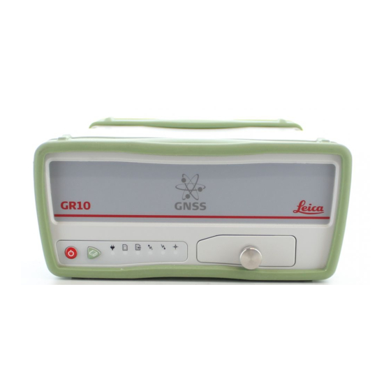
Page 16: Instrument Components
2: Description of the system Instrument Components GR10 components User interface USB and SD card cover Front rubber bumper Back rubber bumper GNSS Antenna port External Oscillator port Serial port (P1) Ruggedised Ethernet port Power port Communication Slot-in port Antenna (P3) -
Page 17: Gr10 Operation
Leica Binary 2 (LB2) interface. Contact your Leica Geosystems representative for information on LB2 documentation. The GR10 instrument is delivered with default settings which cover the needs of the typical user. Use the Web interface or Leica GNSS Spider to adjust the GR10 settings. - Page 18 Operation by Leica GNSS Spider The reference station software Leica GNSS Spider provides some of the same instrument operation functionality as the Web interface. Some configuration settings are available both in the Web Interface and in Leica GNSS Spider. If such settings are configured in the Web interface, and then an Upload Settings or Start is done from GNSS Spider, these will be overwritten.
- Page 19 Printed Documentation • Protect and manage access to RTK correction services using the Spider Business Center advanced user access management. Related topics Keyboard Web Interface: Overview GNSS Spider / Remote Access...
-
Page 20: Software: Overview
Firmware upgrade step-by-step. Leica GNSS Spider can also be used to install the firmware. Loading the firmware to the SD card and installing it on the instrument is done in one step when using GNSS Spider. Refer to the Leica GNSS Spider Online Help for more information. - Page 21 Printed Documentation Receiver Information Important information regarding the instrument details, installed options and firmware can be found on the Status / page on the GR10 Web interface. Receiver Information Related topics Is my firmware up to date? Firmware upgrade step-by-step...
-
Page 22: Power Supply
Up to two external power supplies can be connected using a Y-cable. External power supply: • GEV242 (774437), 110 V/240 V AC to 24 V DC power supply unit, supplied by Leica Geosystems. • 110 V/240 V AC to 12 V DC power supply unit (722409), supplied by Leica Geosystems. -
Page 24: 3: Installation
3: Installation Installation: Overview Menu option Description Before Installation A detailed list of things to consider before installing the GR10, including • Installation location • Installation orientation • Cable installation Installation Detailed diagram of possible installations options • Rack mount •... -
Page 25: Before Installation
Printed Documentation Before Installation Installation location It is recommended that the instrument is installed so that it is • protected from mechanical influences and lightning. • within 70 m of the antenna, without the need to use inline amplifiers. Installation orientation •... -
Page 26: Installation Options
• If space in the rack is limited, then the rubber bumpers on the GR10 can be removed. The total height of the rack kit and instrument is then 2U. If the bumpers are removed, please remove the small feet from the mounting brackets. - Page 27 Printed Documentation Wall / Cabinet Mount Together with the wall mount accessory kit the GR10 can be easily mounted onto an existing wall or structure, or inside an environmental case. • If space in the cabinet is limited, then the rubber bumpers on the GR10 can be removed. If the bumpers are removed, please remove the small feet from the mounting brackets.
- Page 28 3: Installation Free Standing / Stacking The GR10 is designed to allow stable free standing installation and stacking for easy configuration of multiple receivers. • When stacking multiple GR10 instruments on top of each other, the rubber bumpers must be on.
- Page 29 Printed Documentation Tripod The GR10 has a built-in Tripod mount to allow attachment to all Leica Geosystems Tripods. • When using the GR10 on a tripod, the rubber bumpers must be on. AS10 GNSS antenna carrier with 5/8 inch screw...
-
Page 30: 4: User Interface
Function button • Button combinations LED Indicators on GR10 A detailed overview of the LED indicators on the GR10 and their status. USB and SD Card Cover A detailed overview of the USB and SD card slot. Web Interface: Login... -
Page 31: Gr10
Printed Documentation GR10 LED Indicators on GR10 GR10 The GR10 has Light Emitting Diode indicators. They indicate the basic instrument status. Power LED SD card LED Raw data logging LED RT out data stream LED RT in data stream LED... - Page 32 4: User Interface Recommended user action: Immediately activate the Smart clean-up or the automatic file delete for each logging session. No active logging sessions or power is off. Raw data logging LED green Active logging sessions are configured on the instrument and data is being logged.
- Page 33 ON/OFF button Button Function If GR10 already off: Turns on GR10 when held for 2 s. ON/ OFF If GR10 already on: Turns off GR10 when held for 2 s. Hold the ON/OFF button for 10 s, to force the instrument to turn off. Instrument settings and some...
- Page 34 4: User Interface Function button All the following functions described assume the GR10 is already on. Button Function The Function and ON/OFF button work in combination and allow a number different Function functions as described in Button combinations. The Function button switches between these different functions.
- Page 35 Printed Documentation If any data stream had been active, the RT out data stream LED is flashing red. • Press the Function button until the LED flashes quickly to STOP all active data streams if the RT out data stream LED is flashing red. After data streams have been started or stopped, the LED and instrument functionality goes back to general behaviour.
- Page 36 If no SD card is inserted, data storage is not possible. While other SD cards can be used, Leica recommends to only use Leica SD cards and is not responsible for data loss or any other error that can occur while using a non-Leica card.
-
Page 37: Web Interface
Printed Documentation Web interface Web Interface: Login Entering the receivers IP address or host name in a browser window always displays the GR10 web interface login page. • The login page is also shown after user login. • For a partially restricted web interface access, the login as guest button can be used. This login allows access to all Status information. - Page 38 Left of the status block is the content area. This contains the actual information for this page, e.g. status information, a configuration page or links to receive support and information directly from Leica Geosystems AG. Update rates for each element in the status block is as follows: Event log: 5s, Tracking block: 10s, General block: 15s.
- Page 39 Send receiver information and questions to your Leica support contact, stay Support informed about new firmware releases or browse the Leica FAQs to quickly find a solution for common questions. Select to logout of the web interface and return to the main login page.
- Page 40 4: User Interface Icon Description Power status The power status is shown with an icon and the current voltage level. The power level of the connected power source is between 40%-100%. The power level of the connected power source is between 10%-40%. The icon indicates the overall power status.
- Page 41 Printed Documentation necessary. Active logging sessions are configured but • The SD card is full • No navigated position is available. Recommended user action: Check the SD card and the tracking status. The time since the receiver was turned on. This icon is only shown if the receiver is turned on because of an active wake-up session.
- Page 42 4: User Interface Status: Tracking The Tracking box provides an overview of the current tracking status of the receiver. • All satellite systems are listed, independent of the installed option keys. For further information on option keys go to Tools / Options.
- Page 43 Printed Documentation Tracked SBAS satellites on B1. Tracked L1 Tracked SBAS satellites on B2. Tracked L2 The table below describes the icons used in the Tracking box. Icon Description No position, indicates that no navigated position is available. This is displayed after a reboot when the receiver has not started tracking yet.
- Page 44 4: User Interface Hints On each web interface page that allows configuration changes, the shown input fields are described in hints. Hints provide a quick context based help system. For more information consult the online help available via the Show help button For better clarity, the hints are hidden per default.
- Page 45 In the web interface, tool tips are used to explain the functionality of icons and buttons. Move the mouse over an icon to show the tool tip. Move the mouse away from the icon and the tool tip disappears. Related topics LED Indicators on GR10...
-
Page 46: 5: Getting Started
SD card. Step-by-step guides • Use DynDNS and DHCP to automatically assign a host name and all network parameters to a GR10 • Use DynDNS to assign a host name to a GR10 with static IP •... -
Page 47: Network Technology And Protocol Overview
As a result, directly after connecting it the network device can be accessed straightaway by a preconfigured host name. In case of a GR10 this host name is GRxxxxxxx, where “xxxxxxx” has to be replaced by the serial number of the GR10. -
Page 48: Equipment Setup
Step Description Find the power port (PWR) at the back of the GR10. Plug the power cable/GEV238 power supply into the GR10. Insert the SD card into the SD card slot. For more information on how to work with the SD card,... - Page 49 Description Start the computer. To connect the GR10 to the local LAN supporting DHCP, plug an Ethernet cable with a RJ45 connector into the RJ45 Ethernet port on the back of the GR10. Connect the other end of the cable with a network device of your LAN, e.g. hub, switch or router.
- Page 50 5: Getting started Setup in a non - DHCP network If the GR10 receiver is set up in a non-DHCP network, the web interface can still be accessed using a crossed Ethernet cable. Step Description Connect the crossed Ethernet cable to the GR10 receiver and your PC.
- Page 51 Printed Documentation Press OK. Open a browser window and enter 192.168.0.3 to open the GR10 web interface.
- Page 52 5: Getting started Access the instrument via USB Install USB drivers Before connecting the GR10 to a computer using a USB cable, you must first install USB drivers. To install the USB drivers refer to: • Install USB drivers for Windows XP operating systems •...
- Page 53 64 bit CPU: SetupViva&GR_USB_64bit.exe • Itanium 64 bit CPU: SetupViva&GR_USB_64bit_itanium.exe The Welcome to the InstallShield Wizard for Leica Viva & GR USB drivers window appears. Make sure that all GR10 or Viva devices are disconnected from the PC. Click Next>.
- Page 54 Press any key to close the DOS window. Disconnect and reconnect the USB cable. Open a browser and type in the IP address: 192.168.254.2 to access the GR10 web interface. Configure the GR10 for all required settings. Use the default User name (Admin) and Password (12345678).
- Page 55 Loosen the screw on the SD card/USB port cover. Open the SD card/USB port cover. Plug the USB cable into the USB port on the GR10. Plug the USB into the USB port of the computer. Windows will show searching for IP address. Ignore this and go to the next step.
- Page 56 5: Getting started Disconnect and reconnect the USB cable. Open a browser and type in the IP address: 92.168.254.2 to access the GR10 web interface. Configure the GR10 for all required settings. Use the default User name (Admin) and Password (12345678).
- Page 57 Itanium 64 bit CPU: SetupViva&GR_USB_64bit_itanium.exe Wait until the Mobile Device Center Driver Update is finished. The Welcom to the InstallShield Wizard for Leica Viva & GR USB drivers window appears. Click Next>. The Ready to Install the Program window appears.
- Page 58 5: Getting started Disconnect and reconnect the USB cable. Open a browser and type in the IP address: 192.168.254.2 to access the GR10 web interface. Configure the GR10 for all required settings. Use the default User name (Admin) and Password (12345678).
- Page 59 Plug the USB cable into the USB port on the GR10. Plug the USB cable into the USB port of the computer. Open a browser and type in the IP address: 192.168.254.2 to access the GR10 Web interface. Use the default User name (Admin) and Password (12345678).
- Page 60 Select Internet Protocol (TCP/IP) and click on Properties. Pick option Use the following IP address and choose an address in the range of 192.168.254.1 … 192.168.254.255 - except 192.168.254.2 which is the IP of the GR10. Use subnet mask 255.255.255.0.
-
Page 61: Working With The Memory Device
SD card. Failure to follow these instructions could result in data loss and/or permanent damage to the card. Related topics Insert and remove an SD card into GR10 step-by-step Directory structure of the memory device... - Page 62 5: Getting started Insert and remove an SD card into the GR10 step-by-step Step Description The SD card is inserted into a slot inside the SD card/USB port cover on the front of the instrument. Loosen the screw on the SD card/USB port cover.
-
Page 63: Use Dyndns And Dhcp To Automatically Assign A Host Name And All Network Parameters To A Gr10
Click on Save changes to save all settings. Use DynDNS to assign a host name to a GR10 with static IP This procedure requires a DynDNS server. As a result the assigned host name can be used to access the receiver within the network. -
Page 64: Access The Web Interface For The First Time And Change The Default User
Confirm the deletion by clicking on the OK button. After this, the default user Admin will have been deleted. Activate Leica support access step-by-step This section explains how Leica Support can be allowed to access the web interface. Step Description Enter the web interface using a user account having Administrator rights. -
Page 65: Configure Coordinates And Site Name Step-By-Step
Printed Documentation Configure coordinates and site name step-by-step This section explains how to configure site coordinates and site name Step Description Access the web interface. Go to page GNSS management / Site name and coordinates. Enter values in the text field Site code. This four character ID will be used as identifier for the instrument and will be used for the name of logged files (first four characters of the file name). -
Page 66: Configure A Rinex Logging Session Step-By-Step
5: Getting started Configure a RINEX logging session step-by-step This section explains how to configure a continuous RINEX logging session. Step Description Access the web interface. Go to page GNSS management / Logging sessions. Use the button Create a new logging session The logging session wizard will start. -
Page 68: 6: Context Sensitive Help
The Support menu options allow you to send the settings of your Support receiver and debug information to Leica NRS support in order to help solve receiver problems. -
Page 69: Status
Printed Documentation Status Status: Overview View the status of important receiver information, such as the configured logging sessions, the satellite tracking, an overview of the ports in use and the power and memory available. Menu option Description View detailed information about the receiver, including the installed firmware Receiver information version, maintenance data and options. - Page 70 ME serial nu ber The hardware revision of the measurement engine. ME Hardware The default functionality section, list the options that are installed per default on each GR10 receiver. Default functionality Description Ethernet connection is available on every GR10 receiver.
- Page 71 Printed Documentation Related topics Status: Overview Status: Receiver information - Options GNSS management Receiver setup...
- Page 72 To install new options go to Receiver setup / Tools / Options. • To view a detailed description of all options and their article numbers go to GR10 Options. Field description The table below describes the fields in the Status: Receiver information, Options tab.
- Page 73 Printed Documentation Status: Position Background Information Shows the current navigated position and the user entered reference position of the receiver. The receivers position is configured via GNSS Management / Site name and coordinates. • If the entered reference position and the navigated position differ by more than 100m, an error message is displayed.
- Page 74 6: Context sensitive help Status: Tracking Status tracking: General Field Description The table below describes the fields in the Status: General tab. The information shown is dependent on the settings configured on the GNSS management: Tracking page and which satellite options are available on the receiver. If the satellite health setting has been changed to a user defined setting in the GNSS management: Tracking...
- Page 75 Printed Documentation Status tracking: GPS Field Description The table below describes the fields in the Status: GPS tab. The information shown is dependent on the settings configured on the GNSS management: Tracking page and which satellite options are available on the receiver. Press the Refresh icon to update the displayed data.
- Page 76 6: Context sensitive help Status tracking: GLONASS Field Description The table below describes the fields in the Status: GLONASS tab. The information shown is dependent on the settings configured on the GNSS management: Tracking page and which satellite options are available on the receiver. Press the Refresh icon to update the displayed data.
- Page 77 Printed Documentation Status tracking: GALILEO Field Description The table below describes the fields in the Status: GALILEO tab. The information shown is dependent on the settings configured on the GNSS management: Tracking page and which satellite options are available on the receiver. Press the Refresh icon to update the displayed data.
- Page 78 6: Context sensitive help Status tracking: SBAS Field Description The table below describes the fields in the Status: SBAS tab. The information shown is dependent on the settings configured on the GNSS management: Tracking page and which satellite options are available on the receiver. Press the Refresh icon to update the displayed data.
- Page 79 Printed Documentation Status: Data streams Status: Data streams - Outgoing Background information Displays a list of all configured Outgoing data streams from the receiver. Field Description The table below describes the fields in the Data streams / Outgoing tab. The information shown is dependent on the settings configured via the Data stream wizard on the GNSS management: Data streams / Outgoing tab page...
- Page 80 6: Context sensitive help NMEA Description Icon Data stream is active. Data stream is inactive. The configured NMEA messages activated for the outgoing data stream. Message Click the listed NMEA messages to view additional properties NMEA message properties The table below describes the additional NMEA message properties that are shown when the underlined NMEAMessages are selected.
- Page 81 Printed Documentation Related topics GNSS management: Data streams overview GNSS management: Outgoing data stream Streaming session wizard: Configure realtime out data stream Streaming session wizard: Configure LB2 data stream Streaming session wizard: Configure NMEA data stream Streaming session wizard: Configure BINEX data stream...
- Page 82 6: Context sensitive help Status: Data streams - Incoming Background information Displays a list of all configured Incoming data streams from meteo and tilt devices that send data to the receiver. Field Description The table below describes the fields in the Data streams / Incoming tab. The information shown is dependent on the settings configured via the Data stream wizard on the GNSS management: Data streams / Incoming tab...
- Page 83 Printed Documentation Status: Logging sessions Background Information View status information about all configured logging sessions. Configure or edit a logging session via GNSS management / Logging sessions. A logging session wizard will guide you through the procedure. Field Description The table below describes the fields in the Status: Logging session page. The logging sessions can be sorted by each of these criteria by clicking on the header.
- Page 84 6: Context sensitive help Logging session properties The table below describes the additional logging session status information that is shown when the logging session Name is selected. Field Description The configured logging session name. Session name The configured data type. Data type The configured session priority which determines the Smart clean-up tasks.
- Page 85 Printed Documentation For RINEX and Hatanaka logging sessions it will always list the observation file name (*.10o). Related Topics Logging sessions: Overview GNSS management: Logging sessions GNSS management: Smart clean-up...
- Page 86 6: Context sensitive help Status: Port Summary Background Information Shows all ports used in the receiver configuration for data streams, remote access (OWI), FTP and web interface access. For each port the connection status and use case is displayed. Field Description The table below describes the fields on the Status: Port summary page.
- Page 87 Printed Documentation Remote ports Description An icon is shown to indicated the remote connection status. Icon Disconnected Connecting Awaiting connection(s) Connected The connection type and port number configured for the remote port. Data connections: Port The number of connected users on each port. For each remote port a maximum of # Connections one connection per port is possible.
- Page 88 6: Context sensitive help Status: Event log Background Information The Event log contains a list of status and information messages produced by the receiver. The Event log is updated every 5 seconds. The messages from the Event log can be sent to an administrator via an event email. Sending event emails can be configured and activated via Receiver setup / Event log.
- Page 89 Printed Documentation Indicates that an event log filter is currently applied. Press to change the filter Filter details. Filter Event log content Select the Filter icon . Select the filtering limits and then press the Apply icon Field Description Select the interval to view messages From (the selected data and time) and To (the selected data and time). From/ To Activate or deactivate verbose messages.
- Page 90 6: Context sensitive help Status: Network connections Background information Displays all active network connections used to connect the receiver to a network, including DynDNS setup if configured. Possible connections • Ethernet • TCP/IP over USB • Mobile internet • DynDNS Field Descriptions The table below describes the fields in the Status: Network connections page.
- Page 91 Printed Documentation By default, the Ethernet connection is set as the default gateway. The default gateway can be changed to the mobile internet connection. The configured connection used as the default gateway is displayed on top and shows (default gateway) in the header. TCP/IP over USB Description The status of the configured network connection, Connected or Disconnected.
- Page 92 6: Context sensitive help Status: System resources Background information Shows the status of the connected power supply and the used/free space on the inserted SD card. When HTTPS mode is used in Internet Explorer, the graphs shown on the System resources page may not display correctly.
-
Page 93: Gnss Management
Printed Documentation GNSS management GNSS management: Overview Configure all GNSS data related settings, such as logging sessions, data streams and the tracking settings. Or enter site specific information such as the site name, position and antenna details. Menu option Description Enter the site name and coordinates of the receiver. - Page 94 6: Context sensitive help GNSS management: Site name and coordinates Background Information Site name and coordinates is used to enter the reference station information that will be used for real time correction messages and raw data logging. Changing the site name and/or coordinates interrupts logging and streaming. If any of these settings are changed when a logging session is active then the current files will be finalized and new file(s) will start to be logged.
- Page 95 Printed Documentation Enter a marker name. Marker name • The marker name is used to occupy the equivalent entry in the RINEX header when creating RINEX files for this site. • If no Marker Name is entered then it will default to the Site Name. If no site name is entered, the marker name field in the RINEX header will stay empty.
- Page 96 6: Context sensitive help Coordinates Description Choose the coordinate type, either Geodetic or Cartesian. Coordin te Type The latitude of the site. Latitude The longitude of the site. Longitude The ellipsoidal height of the site. Ellipsoidal height Time settings Description Select the time zone.
- Page 97 Printed Documentation GNSS management: Tracking GNSS management: Tracking General Background information Tracking configuration options may be used to control which satellite systems are tracked by the receiver and to set the tracking modes. If an external oscillator is selected but not connected, the receiver will not track any satellite signals.
- Page 98 6: Context sensitive help An external oscillator can be used to provide a better quality time signal to the Oscillator receiver than the receiver's own internal clock. The same external oscillator can also be used with a number of receivers so that each receiver is guaranteed to be tracking satellites using the same time signal.
- Page 99 Printed Documentation Related topics GNSS management: Tracking GPS GNSS management: Tracking GLONASS GNSS management: Tracking GALILEO...
- Page 100 6: Context sensitive help GNSS management: Tracking GPS Background information Tracking GPS options, may be used to control which health settings are used for each GPS satellite tracked by the receiver. Setting Descriptions The table below describes the settings that can be configured on the Tracking GPS tab. Field Description For each tracked satellite it is possible to set the health as Auto, Healthy or Bad.
- Page 101 Printed Documentation GNSS management: Tracking GLONASS Background information Tracking GLONASS options may be used to control which health settings are used for each GLONASS satellite tracked by the receiver. Setting Descriptions The table below describes the settings that can be configured on the Tracking GLONASS tab. Field Description For each tracked satellite it is possible to set the health as Auto, Healthy or Bad.
- Page 102 6: Context sensitive help GNSS management: Tracking GALILEO Background information Tracking Galileo options may be used to control which health settings are used for each Galileo satellite tracked by the receiver. Setting Descriptions The table below describes the settings that can be configured on the Tracking GALILEO tab. Field Description For each tracked satellite it is possible to set the health as Auto, Healthy or Bad.
- Page 103 Printed Documentation GNSS management: Data streams GNSS management: Data streams overview Description Configure outgoing realtime, LB2 (Leica Binary), NMEA GNSS management: Outgoing data stream or BINEX messages from the receiver. Configure incoming meteo and tilt data streams to the GNSS management: Incoming data streams...
- Page 104 Background Information This page provides an overview of the configured outgoing data streams. Configure outgoing realtime, LB2 (Leica Binary), NMEA or BINEX messages from the receiver by pressing Create new data stream The maximum number of configured outgoing data streams is 22, 20 TCP/IP connections and 2 serial connection available.
- Page 105 Create new data stream stream wizard opens. The wizard is a tool that guides you through the following stages of an outgoing data stream configuration: • Streamed data types - realtime, LB2 (Leica Binary), NMEA or BINEX • Message selection •...
- Page 106 6: Context sensitive help Outgoing data stream wizard: Select data stream Setting Descriptions The table below describes the settings that can be configured on the Select data stream page. Setting Description Select the data stream type. Data stream type • Realtime •...
- Page 107 Description The proprietary Leica real-time data format supporting Leica GPS and GLONASS. This is the best format to use when working exclusively with Leica Viva rovers or other Leica rover units. Leica proprietary RT format supporting GPS (including Leica 4G L5), GLONASS and Galileo.
- Page 108 6: Context sensitive help and 19. Additional messages sent: 3, 22, 23, 24 Output of both Code corrections and uncorrected carrier RTCM 2.x phase data. (Type 1,2,18,19) Additional messages sent: 3, 22, 23, 24 Output of both Code and carrier phase corrections. RTCM 2.x Additional messages sent: 3, 22, 23, 24 (Type 1,2,20,21)
- Page 109 Printed Documentation realtime message from different reference stations are sent on the same radio channel. Only visible when Time slicing is checked. Nr of reference stations Select the number of reference stations in use from where realtime messages are sent on the same radio channel.
- Page 110 6: Context sensitive help Outgoing data stream wizard: Configure LB2 data stream Background Information LB2 is the Leica proprietary binary protocol to interface with the receiver. An outgoing LB2 stream can contain measurement data and/or satellite data. Setting Descriptions The table below describes the settings that can be configured on the Configure LB2 data stream page.
- Page 111 Printed Documentation Outgoing data stream wizard: Configure NMEA data stream Setting Descriptions The table below describes the settings that can be configured on the Configure NMEA data stream page. Setting Description Activate or deactivate the NMEA message check boxes that are to be output. Message A detailed description of each NMEA message is contained in Appendix B: NMEA...
- Page 112 6: Context sensitive help Outgoing data stream wizard: Configure BINEX data stream Background Information BINEX (Binary Exchange Format) is an exchange format for GNSS data defined by UNAVCO. You can find more information about BINEX at http://binex.unavco.org. The configuration wizard includes a check box table which enables and disables individual BINEX messages.
- Page 113 Printed Documentation Outgoing data stream wizard: Connection Background Information Data can be streamed from the GR10 using a variety of communication types. Setting Descriptions The table below describes the settings that can be configured on the Connection page. Setting Description Select the connection type.
- Page 114 This setting is only available for receivers with the GRL115, Multi-Client option key loaded. For all other receivers the number of users is fixed to 1. The option can be purchased from Leica Geosystems. Select the range of IP addresses, which are authorized to access the receiver. The Limit access range IP range is from 1.0.0.0 to 254.254.254.254.
- Page 115 Printed Documentation Outgoing data stream wizard: Configure TCP/IP client Background Information The TCP/IP client connection setting allows the receiver to act as a TCP client and send data out to a configured IP address and port. This way no port has to be opened in the firewall to allow clients to connect to the receiver. Furthermore since the data stream is now sent to a PC port, the number of connections to the data stream is not limited by the receiver.
- Page 116 6: Context sensitive help Outgoing data stream wizard: Configure NTRIP server (source) Background Information This mode allows the receiver to act as Ntrip Server, and to provide data to an Ntrip Caster. In terms of TCP/IP, the Ntrip server mode is in fact a TCP client mode. As an Ntrip Server, the receiver connects to a caster and starts to stream data.
- Page 117 Printed Documentation Outgoing data stream wizard: Configure Serial port Background Information This mode allows data to streamed out of the physical serial port (P1). This page allows you to change the settings of the instrument's serial port. Do not select the connection type Serial Port if you have a radio/modem/phone connected to the serial port (P1).
- Page 118 Background Information This mode allows data to be transmitted with an attached Radio device. The GR10 supports eight different types of radios including seven which attach to the Serial Port (P1) via a serial cable and one which attached to the Slot in port (P3).
- Page 119 Printed Documentation Outgoing data stream wizard: Configure GSM / Modem / CDMA - dial up Background Information This mode allows data to be transmitted with an attached GSM, Modem or CDMA - dial up service device. There are a number of default devices defined in the Receiver settings: Device Management page.
- Page 120 6: Context sensitive help Outgoing data stream wizard: Set streaming status Setting Descriptions The table below describes the settings that can be configured on the Set streaming status page. Setting Description Deactivate the data stream if you do not want it to run immediately. Activate data stream Press to go back to the previous wizard step.
- Page 121 Printed Documentation GNSS management: Incoming data streams GNSS management: Incoming data streams Background Information This page provides an overview of the configured incoming data streams. Configure an incoming meteo or tilt data stream to the receiver by pressing Create new data stream •...
- Page 122 6: Context sensitive help Click to open the Create new data stream wizard. Create new data stream The data stream wizard guides the user through the • creation of a new incoming data stream, or • editing of an existing data stream. Data stream wizard Upon pressing Create new data stream in the GNSS management / Incoming data stream page, the Incoming data stream wizard opens.
- Page 123 Printed Documentation Incoming data stream wizard: Select data stream Setting Descriptions The table below describes the settings that can be configured on the Select data stream page. Setting Description Select the incoming data stream type. Data stream type • Meteo •...
- Page 124 6: Context sensitive help Incoming data stream wizard: Configure Meteo Background Information Meteorological sensors are used for measuring air pressure, temperature and relative humidity. The data from the meteo sensor is logged together with the GPS raw observations into the MDB and RINEX files. If RINEX logging is active, an additional meteo RINEX file is created that contains the data from the meteo sensor.
-
Page 125: Nivel210 Default Communication Settings
Background Information Tilt devices (such as the Leica NIVEL210) are used for measuring inclinations. The data from the tilt device is logged together with the GPS raw observations into MDB files. When logging RINEX files, the tilt data is written into a special auxiliary file. - Page 126 6: Context sensitive help Incoming data stream wizard: Set streaming status Setting Descriptions The table below describes the settings that can be configured on the Set streaming status page. Setting Description Deactivate the data stream if you do not want it to run immediately. Activate data stream Press to store the data stream configuration.
- Page 127 Printed Documentation GNSS management: Logging sessions GNSS management: Logging sessions overview Description Configure, create or edit a logging session. GNSS management: Logging sessions Enable and disable the smart clean-up of logging session files on GNSS management: Smart clean-up the receiver.
- Page 128 • All files can be directly imported into Leica Geo Office (LGO). All MDB files can also be downloaded via GNSS Spider. • If you wish to push the logging session data to an FTP server, an...
- Page 129 Printed Documentation Press delete to permanently delete the logging session. Delete Note: This will delete all corresponding files from the SD card. It cannot be undone! Press to edit the logging session settings. The Logging session Edit logging session wizard will open. The Session name and Data Type cannot be edited.
- Page 130 6: Context sensitive help Logging session wizard Upon pressing Create a new Logging session, the Logging session wizard opens. The wizard is a tool that guides the user through the following stages of a logging session configuration: • Logging session name, data types, priority and session type •...
- Page 131 Printed Documentation GNSS management: Smart clean-up Background Information The SD card in the receiver can run full if the logging session data files are not removed (e.g. by FTP push or download). Smart clean-up ensures that the SD card will not run full, while preserving the data that has the highest priority to the user.
- Page 132 6: Context sensitive help All running logging sessions will continue logging as configured, until the SD card is full. All logging sessions will then stop logging data. Leave this setting unchecked if you don't want to loose old data and are unaffected by the possibility of all logging sessions stopping due to a full SD card.
- Page 133 Printed Documentation Create new Logging session - Logging session wizard Logging session wizard: Create a new logging session / Edit a logging session Setting Descriptions The table below describes the settings that can be configured on the Create/Edit a logging session page. Setting Description Enter a unique logging session name.
- Page 134 6: Context sensitive help Do not change a logging session created by Leica GNSS Spider into a timed logging session. Spider can not configure timed logging sessions. • Continuous: Select to define the data type file length only. If a continuous session type is activated, it will start logging immediately.
- Page 135 Printed Documentation Logging session wizard: Session timing Background information Timed logging sessions consider the configured file length and the configured interval length. Example:If a timed logging session is configured to • Start logging at a certain date at 15:00h • End logging after 30min •...
- Page 136 6: Context sensitive help Select • Select run to enter a number of repetitions for this logging session. • Select repeat infinitely to configure a logging session with no defined end. • Select run once to configure only one interval for a logging session.
- Page 137 Printed Documentation Logging session wizard: MDB Setting Descriptions The table below describes the settings that can be configured on the MDB page. Setting Description Select the rate at which the observations are to be logged. Logging rate Note: a faster logging rate results in higher resource consumption on the receiver.
- Page 138 6: Context sensitive help Logging session wizard: RINEX Setting Descriptions The table below describes the settings that can be configured on the RINEX page. Setting Description Select the rate at which the observations are to be logged. Logging rate Note: A faster logging rate results in higher resource consumption on the receiver.
- Page 139 Printed Documentation Press to go back to the previous wizard step. Press to continue to the next wizard step. Press to cancel and return to GNSS management: Logging session.
- Page 140 6: Context sensitive help Logging session wizard: Compact RINEX (Hatanaka) Setting Descriptions The table below describes the settings that can be configured on the Compact RINEX (Hatanaka) page. Setting Description Select the rate at which the observations are to be logged. Logging rate Note: A faster logging rate results in higher resource consumption on the receiver.
- Page 141 Printed Documentation Press to go back to the previous wizard step. Press to continue to the next wizard step. Press to cancel and return to GNSS management: Logging session.
- Page 142 6: Context sensitive help Logging session wizard: Data handling Setting Descriptions The table below describes the settings that can be configured on the Data handling page. Setting Description Activate to ZIP the logging session files. Zip files Select the directory naming convention. Directory naming convention This is the folder structure that will be used on the SD card and on the FTP server (when FTP push is used) to store the logging files.
- Page 143 Printed Documentation Logging session wizard: Set logging status Setting Descriptions The table below describes the settings that can be configured on the Set logging status page. Setting Description Activate session Deactivate the logging session if you do not want it to run immediately. Press to go back to the previous wizard step.
- Page 144 6: Context sensitive help GNSS management: FTP locations GNSS management: FTP locations Background Information FTP locations configuration allows the user to • Add new FTP locations • Edit and delete FTP locations • View information about existing FTP locations FTP locations are used to push data created by a logging session on the receiver to an external FTP server. Each FTP location can be used in several logging sessions.
-
Page 145: Related Topics
Printed Documentation Press to clear the queue of pending files to be pushed to an FTP Clear location. This deletes a backlog of files caused by for example, FTP sever unavailability. • The Clear icon is only shown when the Queue number is greater than zero. - Page 146 6: Context sensitive help GNSS management: New / Edit FTP location Background Information Enter the necessary access information for pushing logged data from the GR receivers SD card to an external FTP server. Setting Descriptions The table below describes the fields in the New / Edit FTP location page. Setting Description Enter a unique FTP location name.
- Page 147 Printed Documentation GNSS management: Antenna management GNSS management: Antenna Management overview Description Select an antenna and enter the height reading and measurement Select antenna type. Upload new antenna files, create new antennas and restore Antenna management antenna default values.
- Page 148 6: Context sensitive help GNSS management: Select antenna Background information Select the antenna currently connected to the receiver and enter the height reading and measurement type. Correctly specifying the antenna and related information is critical for high accuracy positioning. Changing the antenna type and/or antenna height interrupts logging and streaming. If any of these settings are changed when a logging session is active, then the current files will be finalized and new file(s) will start to be logged.
- Page 149 Printed Documentation GNSS management: Antenna management Background information Upload new antenna files, create new antennas and restore antenna default values. Field Descriptions The table below describes the fields in the Antenna management tab. Field Description The name of the antenna file. All antenna files loaded onto Loadable antenna files the SD card are shown.
- Page 150 6: Context sensitive help defined antennas will not be deleted. The restore default button fills all fields with the default values and stores these values. Pressing the save button is not necessary. When accepting the confirmation message, all settings on this page are overwritten with the default settings.
- Page 151 Printed Documentation GNSS management: Create/Edit an Antenna Field Descriptions The table below describes the fields in the Create/Edit an Antenna tab. Field Description The antenna name. Name When editing an existing antenna, the antenna name can not be changed. Horizontal distance from the physical reference point (ARP) to the point on the antenna Horizontal offset where the slope height reading is measured.
- Page 152 GNSS management: Calculate the antenna height reading The pictures below show examples for a standard setup of a Leica AT504/AT504 GG antenna on a pillar and a tripod. They also illustrate the antenna height reading values and give an example of what a permanent antenna setup could look like.
- Page 153 Printed Documentation Slope measurement type Note: If the Offset Point on the antenna is above the Physical Reference Plane BPA, the Vertical Offset VO is negative! Vertical measurement type Antenna Height = VR + VO...
- Page 154 6: Context sensitive help GNSS management: Wake-up sessions GNSS management: Wake-up sessions Background Information GNSS management setup: Wake-up sessions allows the user to • Configure new wake-up sessions. • Edit and delete existing wake-up sessions. • View information about existing wake-up sessions. Wake-up sessions define a number of intervals for which the receiver is configured to run.
- Page 155 Printed Documentation of the interval. • During a wake-up session all data streams and logging sessions that had been configured and activated before the start of the wake-up session will automatically resume streaming and logging. Additional data streams and logging sessions can be configured during the intervals.
- Page 156 6: Context sensitive help Wake-up session properties The table below describes the content of the Wake-up session properties pop up box. Press on the underlined Wake- up session name to open the pop-up box. Properties Description The configured name of the wake-up session. Name The start time and date of the first wake-up interval of this session.
- Page 157 Printed Documentation GNSS management: New/Edit wake-up session Setting Descriptions The table below describes the fields in the New/Edit wake-up session page. This page opens when creating a new Wake-up session with the Create new wake-up session button. Setting Description Enter a unique name for the wake-up session. Name If the Wake-up session is created from a logging session, the default name is derived from the logging session name.
- Page 158 6: Context sensitive help interval. The maximum time between 2 consecutive start times is 21 days. Activate this check box to activate the wake-up session. Activate Wake-up session Save the settings by pressing . This will redirect to the Wake-up session overview page where all configured wake-up sessions are listed.
-
Page 159: Receiver Setup
Printed Documentation Receiver setup Receiver Setup: Overview Configure all receiver related settings such as network connections, FTP push locations and the user management. Or use the tools to upgrade the receiver firmware, add new option keys or switch to your preferred language. Menu option Description Configure the receiver IP and DNS settings to allow access via the internet. - Page 160 6: Context sensitive help Network connections Network connections: Overview The Network connections page allows defining the access to the receiver via an internet connection. Tab option Description Configure the Ethernet settings which will the enable the receiver to be accessed via the Ethernet internet.
- Page 161 Printed Documentation Network connections: Ethernet Background Information Ethernet configuration enables the receiver to be accessed via the internet when an Ethernet cable is connected. Setting Descriptions The table below describes the settings that can be configured on the Ethernet tab. Hostname Description Enter a hostname (device name) for the receiver.
- Page 162 6: Context sensitive help field is disabled. The IP address is a 32 bit number which must be obtained from the network administrator or the internet service provider. The format of the IP address is aaa.bbb.ccc.ddd where aaa is a value ranging from 001 to 223 and bbb, ccc and ddd are values ranging from 000 to 255.
- Page 163 Printed Documentation Network connections: Mobile internet Background Information Use mobile internet configuration to configure mobile internet access (e.g. via GPRS device) to the receiver. Setting Descriptions The table below describes the settings that can be configured on the Mobile internet page. Configure device for internet Description usage...
- Page 164 6: Context sensitive help Access Management Access Management: Overview Access Management is used to control access to the receiver via the web interface and FTP. Tab option Description • User management View configured users • Create new users • Delete users •...
- Page 165 Printed Documentation Access Management: User management Background Information User management configuration allows the Administrator to • View configured users • Create new users • Delete users • Edit users details and password Setting Descriptions The table below describes the settings that can be configured on the User management tab. Field Description The configured user name.
- Page 166 6: Context sensitive help Pressing the save button is not necessary. When accepting the confirmation message, all settings on this page are overwritten with the default settings. Related topics Access Management: Access settings Access Management: New user / Edit User...
- Page 167 Printed Documentation Access Management: Access settings Background Information The access settings allow the Administrator to • configure the user access to the web interface • Access a link to the FTP server access restrictions page Setting Descriptions The table below describes the settings that can be configured on the Access settings tab. Field Description Set the security level for web interface access.
- Page 168 6: Context sensitive help Web interface access description The Web interface access description provides a summary of which menus will be available for each user depending on • whether the selected Access to Web interface is: Unrestricted, Partially restricted or Fully restricted, and •...
- Page 169 Printed Documentation New User / Edit User Setting Descriptions The table below describes the settings that can be configured on the New User / Edit User page. Field Description Enter a unique user name. User name • Maximum number of characters allowed is 30. •...
- Page 170 6: Context sensitive help or Fully restricted. Go to Receiver Setup / Access management / Access tab, to change this setting. settings The Web interface access description below provides a summary of which pages will be available for each user depending on the access level. Select the FTP server access level.
- Page 171 Printed Documentation Status with login or guest login with with login with login or or guest login or guest login guest Partially login login restricted GNSS with login with management login access access Receiver with login Limited Change setup access password access only...
- Page 172 Spider and remote access: Overview Background Information The Spider and remote access configuration page lists all ports on the GR10 receiver that are open for any OWI based tool to connect to the receiver and change the settings via OWI commands.
- Page 173 The wizard is a tool that guides you through the following stages of a remote access configuration: Connection type - Select if you want to connect the GR10 to the Spider site server via TCP/IP server, TCP/IP client, Serial port, Radio or GSM / Modem / CDMA - dial up...
- Page 174 The table below describes the settings that can be configured on the Connection page. Setting Description Select the connection type that is needed for Leica GNSS Spider or other OWI based Connection type software to connect to the receiver. TCP/IP server...
- Page 175 The table below describes the settings that can be configured on the Configure TCP/IP server page. Setting Description Enter the TCP/IP port of the receiver for Leica GNSS Spider or other OWI based TCP/IP port software to connect to. Select the range of IP addresses which are authorized to access the receiver. The Limit access range available IP range is from 1.0.0.0 to 254.254.254.254.
- Page 176 6: Context sensitive help Remote access wizard: Configure TCP/IP client Background Information The TCP/IP client connection setting allows the receiver to act as a TCP client and connect to a configured IP address and port. This way no port has to be opened in the firewall on the receiver side to allow clients to connect to the receiver.
- Page 177 Remote access wizard: Configure Serial port Background Information The Configure Serial port settings, allow configuring a connection to a computer, for when the GR10 receiver is connected directly via a serial cable. The settings for the Com port on the computer must match the settings for the serial connection on the receiver.
- Page 178 Radios can be used to connect the receiver to Leica GNSS Spider or other OWI based software, if the radios are configured for two-way communication. The radio on the Leica GNSS Spider side must be pre-configured in a way that it can be addressed as serial device. Go to Receiver Setup / Device Management page to change the communication settings of a device if needed.
- Page 179 Remote access wizard: Configure GSM / Modem / CDMA Background Information The settings on this page allow Leica GNSS Spider or other OWI based software to use a modem to dial into a modem connected to the GR10 and configure the receiver.
- Page 180 6: Context sensitive help Remote access wizard: Set port status Setting Descriptions The table below describes the settings that can be configured on the Set port status page. Setting Description Deactivate the port configuration if you do not want to open the port Activate remote access immediately.
- Page 181 This will open a pop up box showing information about the web site and the trusted third party that issued the certificate. For the standard SSL certificate on your receivers web interface, Leica Geosystems AG will be shown as the third party that issued the SSL certificate.
- Page 182 Such a self signed certificate is the default that comes with the GR10 web site. The URL of the web site is not verified (as this is different for every receiver) and the certificate is self signed by Leica Geosystems AG.
- Page 183 Printed Documentation Setting Descriptions The table below describes the fields in the Web server page. The keyboard short cuts CTRL +C and CTRL +V can be used to copy and paste the SLL certificate and SSI key into the web interface. Setting Description Select the protocol...
- Page 184 6: Context sensitive help * 2. Redistributions in binary form must reproduce the above copyright notice, this list of conditions and the following disclaimer in the documentation and/or other materials provided with the distribution. * 3. All advertising materials mentioning features or use of this software must display the following acknowledgment: "This product includes software developed by the OpenSSL Project for use in the OpenSSL Toolkit.
- Page 185 Printed Documentation * THIS SOFTWARE IS PROVIDED BY THE OpenSSL PROJECT ``AS IS'' AND ANY * EXPRESSED OR IMPLIED WARRANTIES, INCLUDING, BUT NOT LIMITED TO, THE * IMPLIED WARRANTIES OF MERCHANTABILITY AND FITNESS FOR A PARTICULAR * PURPOSE ARE DISCLAIMED. IN NO EVENT SHALL THE OpenSSL PROJECT OR * ITS CONTRIBUTORS BE LIABLE FOR ANY DIRECT, INDIRECT, INCIDENTAL, * SPECIAL, EXEMPLARY, OR CONSEQUENTIAL DAMAGES (INCLUDING, BUT * NOT LIMITED TO, PROCUREMENT OF SUBSTITUTE GOODS OR SERVICES;...
- Page 186 6: Context sensitive help * apply to all code found in this distribution, be it the RC4, RSA, * lhash, DES, etc., code; not just the SSL code. The SSL documentation * included with this distribution is covered by the same copyright terms * except that the holder is Tim Hudson (tjh@cryptsoft.com).
- Page 187 Printed Documentation * being used are not cryptographic related :-). * 4. If you include any Windows specific code (or a derivative thereof) from * the apps directory (application code) you must include an acknowledgement: * "This product includes software written by Tim Hudson (tjh@cryptsoft.com)" * THIS SOFTWARE IS PROVIDED BY ERIC YOUNG ``AS IS'' AND * ANY EXPRESS OR IMPLIED WARRANTIES, INCLUDING, BUT NOT LIMITED TO, THE * IMPLIED WARRANTIES OF MERCHANTABILITY AND FITNESS FOR A PARTICULAR PURPOSE...
- Page 188 IP address. The typical use case for this functionality is a receiver with an internet connection via a GPRS / mobile internet device. In this setup the GR10 receiver will have a different IP address every time the internet connection is established.
- Page 189 Printed Documentation DynDNS step-by-step Follow this procedure to enable using DynDNS on the GR receiver: Step Action Register at DynDNS service: Go to one of the supported DynDNS services and register for an account. At registration enter the hostname you want your receiver to be accessed with. Enable wildcard use.
- Page 190 The table below describes the settings that can be configured on the DynDNS page. Field Description Lists all available DynDNS service providers. Select the provider that the hostname of Service provider your receiver has been registered with. The GR10 supports • DynDNS.com • No-ip.com •...
- Page 191 Default: 180 A maximum of 6 simultaneous connections is possible on the GR10 FTP server. Press to fill the form with factory default settings and store. Restore default values The restore default button fills all fields with the default values and stores these values.
- Page 192 6: Context sensitive help Device Management Device Management: Overview Device Management is used to create, configure or delete modem, radio and GSM devices to be used with the receiver. Tab option Description • Modem / Phone View all default and user defined modem and phone devices •...
- Page 193 Printed Documentation Device Management: Modem / Phone Background Information Create, configure or delete modem and phone (GSM) devices to be used with the receiver. Setting Descriptions The table below describes the settings that can be configured on the Modem / Phone tab. Settings Description Icon...
- Page 194 6: Context sensitive help Device Management: Radio Background Information View and delete radio devices to be used with the receiver. Setting Descriptions The table below describes the settings that can be viewed on the Radio tab. Settings Description Icon Device is in use. If a device is in use it cannot be deleted.
- Page 195 Printed Documentation Device Management: New / Edit modem/phone device Setting Descriptions The table below describes the settings that can be configured on the New / Edit modem/phone page. Settings Description Lists the device type. Device type Enter or edit the device name. Device name Configure if the device can be used to access the internet.
- Page 196 6: Context sensitive help Device Management: GPRS / Internet initialization Setting Descriptions The table below describes the settings that can be configured on the GPRS / Internet initialization page. is set to Yes on the New / Edit modem/phone page. This page is only shown when Mobile internet capable Settings...
- Page 197 Printed Documentation Device Management: GSM / CSD initialization Setting Descriptions The table below describes the settings that can be configured on the GSM / CSD initialization page. Settings Description Enter a valid AT command to initialize the device. Init string 1 Enter a valid AT command to initialize the device.
- Page 198 6: Context sensitive help Receiver setup: Event log Background Information The Configuration: Event log page is used for configuring and editing the settings for sending automatic event emails containing all messages from the event log. The page also allows settings the automatic delete interval for all event log messages. Setting Descriptions The table below describes the settings that can be configured on the Event log page.
- Page 199 Printed Documentation Please note that verbose messages are not included in Event emails. Go to Status / Event log, adjust the filter settings to include verbose messages and use the download button in order to have all messages, including the verbose messages. This procedure should be applied before contacting support.
- Page 200 6: Context sensitive help Receiver setup: Power management Background Information Configure the power up and low power behaviour of the receiver according to the intended use case. Setting Descriptions The table below describes the settings that can be configured on the Power management page. Boot receiver on pulse to Description port...
- Page 201 Printed Documentation Receiver setup: Tools Receiver Setup: Tools - Overview The Receiver Setup: Tools page allows: Tab option Description Power down and reboot the receiver, format the SD card, initialise the Tools ephemeris and almanac and reset and store the receiver settings. Load and delete firmware files.
- Page 202 Description Press to power down the receiver. After power down, the web Power down interface will redirect to the Leica Geosystems GR10 web site. Press to reboot the receiver. After reboot, you will be redirected to Reboot the Web interface login page.
- Page 203 The actions, Reboot, Format SD card, Format receiver settings and Initialize measurement engine, if executed, will result in the receiver rebooting. Related topics Appendix F: GR10 default settings Format receiver settings via Web interface step-by-step Format receiver settings via instrument buttons step-by-step...
- Page 204 • Is my firmware up to date? • Firmware upgrade step-by-step • Firmware upgrade using Leica GNSS Spider • Loading a Language file Please ensure that there are no power interruptions during the firmware upgrade ! Setting Descriptions The table below describes the fields in the Firmware tab.
- Page 205 Printed Documentation Available firmware updates Description The name of the firmware file available for download from the Leica Available firmware updates web site. This field shows if there is a later firmware version available on the Leica web site than the one installed on the receiver.
- Page 206 6: Context sensitive help Receiver setup: Option management Background Information The Option management page allows the installation and deletion of options, and provides an overview of all purchased options that are currently installed on the receiver. Setting Descriptions The table below describes the information that is contained in the Options tab. Field Description To install a new option either:...
- Page 207 Printed Documentation GR10 options Available options for a GR10 receiver: Article number Option Description 774411 GRL100, GPS L5 Enables GPS L5 tracking. 774422 GRL101, GLONASS Enables GLONASS L1+ L2 tracking. 774424 GRL103, Galileo Enables Galileo, L1,E5a, E5b and AltBOC tracking.
- Page 208 The default language is English. English will always be used if the provided language file does not contain a translated token. For more information on translating please contact your local Leica Geosystems Dealer/Distributor in the country where you bought your product.
- Page 209 GR10 receiver. With the backup functionality the receiver settings can be stored for archiving or the file can be used on other GR10 receivers if the configuration is to be the same on several receivers. The system configuration is stored in a zipped file.
- Page 210 6: Context sensitive help File upload Press Browse... to select the new option, language, antenna, receiver configuration or firmware file from the computer. Press the upload icon to complete the upload of the new file from the computer to the receiver.
-
Page 211: Support
Printed Documentation Support Support: Overview The Support menu options allow you to send the settings of your receiver and debug information to Leica NRS support in order to help solve receiver problems. Menu option Description Activate the automatic sending of dump file to NRS support everytime the Properties receiver stops operating. - Page 212 Activate the automatic sending of dump files to Network Reference Stations support every time the receiver stops operating. The FTP push to Leica NRS support only works if there is an active connection to the internet. If the internet connection is down, and the FTP push fails, then the dump files can be found in the Transfer / Settings folder on the SD card.
- Page 213 Network Reference Stations support. In the case that the Leica SMTP server cannot be reached, e.g. due to network connectivity issues on the reference site, the zip file containing the receiver settings can be downloaded from the Transfer / Settings directory on the SD card.
- Page 214 During a support incident you may be asked by Leica support staff to connect to Active Assist. Active Assist allows access to your receiver's web interface by Leica NRS support staff in a protected network. Press the Connect button in order to initiate the connection to the Active Assist server.
-
Page 216: 7: Gr10 Software
Firmware upgrade step-by-step. Leica GNSS Spider can also be used to install the firmware. Loading the firmware to the SD card and installing it on the instrument is done in one step when using GNSS Spider. Refer to the Leica GNSS Spider Online Help for more information. - Page 217 Printed Documentation Receiver Information Important information regarding the instrument details, installed options and firmware can be found on the Status / page on the GR10 Web interface. Receiver Information Related topics Is my firmware up to date? Firmware upgrade step-by-step...
-
Page 218: Is My Firmware Up To Date
7: GR10 Software Is my firmware up to date? If the GR10 is connected to the internet, the web interface automatically notifies the user if a new firmware version becomes available. This message appears in the following places: • in the Event log •... -
Page 219: Firmware Upgrade Step-By-Step
If the Maintenance End date shown is later than in the corresponding release notes, then this firmware can be loaded. If the Maintenance End date is no longer valid, then please contact your local Leica Representative to learn about Customer Care Packages (CCPs) that include software maintenance so that you can benefit from the latest software improvements. - Page 220 Open an FTP client such as Windows Explorer or any other software capable of establishing an FTP connection. Enter the IP address (hostname) of the GR10 and the username and password of a user with FTP server read/write access. Copy the firmware file into the Transfer / Firmware folder on the SD Card.
- Page 221 4: Install the firmware After uploading, the firmware must be transferred from the SD card to the System RAM via the Web interface. Prior to starting the installation, ensure that the GR10 is connected to a reliable power supply. Step Description Go to the Receiver Setup / Tools / Firmware page.
-
Page 222: Firmware Upgrade Using Leica Gnss Spider
7: GR10 Software Firmware upgrade using Leica GNSS Spider Leica GNSS Spider can also be used to install the firmware. Loading the firmware to the SD card and installing it on the instrument is done in one step when using GNSS Spider. -
Page 223: Loading A Language File
Follow these steps to upload a new language file: Step Description Go to the Receiver Setup / Tools / Languages page in the GR10 Web interface. Click, Upload new language file Click the Browse… button and select the new language file . -
Page 224: 8: Gnss Spider / Remote Access
GNSS Spider / Remote Access An overview of the GNSS Spider, remote access process and the requirements that are required. GNSS Spider <-> GR10 configuration An overview of how settings are stored on the receiver when using GNSS Spider. GNSS Spider logging session An overview of GNSS Spider logging sessions. -
Page 225: Gnns Spider / Remote Access
• Radio It is also possible to connect a GR10 receiver to the GNSS Spider site server via a USB connection. In this case, the connection will be handled like a network connection via an Ethernet cable. Please see the chapter... - Page 226 8: GNSS Spider / Remote Access Licensing Leica GNSS Spider users do not need a license to connect the GR10 as an active site to the Leica GNSS Spider software. Requirement: GR10: Leica GNSS Spider v4.0 or later must be installed.
-
Page 227: Gnss Spider <-> Gr10 Configuration
GNSS Spider <-> GR10 configuration When working with a GR10 and an active connection to Leica GNSS Spider, the settings on the receiver can be changed from either side. The last stored/uploaded settings will overwrite everything that had been configured before. -
Page 228: Gnss Spider Logging Session
MDB logging on the GR10 can be configured and started from GNSS Spider via an active site. Please see the GNSS Spider online help for more information on how to configure an active GR10 site. Only one logging session can be configured and started from GNSS Spider. -
Page 229: Gnss Spider Data Streams
Spider is started. When the site is stopped, the data streams are deleted from the receiver. No data streams can be deactivated from GNSS Spider on the GR10. Data streams created in GNSS Spider and uploaded to the receiver can however be deactivated in the web interface... -
Page 230: 9: How To
9: How to How to: Overview The following topics provide detailed step-by-step guides to help you configure your receiver: • How to set up a mobile internet connection • How to use DynDNS service on receiver • How to backup and restore receiver settings •... -
Page 231: How To Set Up A Mobile Internet Connection
A GPRS enabled device is necessary to establish this connection. Before you begin In order to connect to the internet from the GR10 receiver, it is necessary to apply for an APN (access point name) from your internet service provider. - Page 232 9: How to Related topics Slot-in devices Device Management: New / Edit modem/phone device Status: Network connections...
-
Page 233: How To Use Dyndns Service On Receiver
IP address every time the internet connection is established. Another use case is a GR10 behind a router in a local network, where the router is connected to the internet and regularly gets an updated IP address. The GR10 will check every 12min for a new IP address on the router and updates the DynDNS settings when neccessary. -
Page 234: How To Backup And Restore Receiver Settings
9: How to How to backup and restore receiver settings Background information If several receivers are to be used with the same configuration, with differences in the coordinates and IP settings only, it would be convenient to not have to type in these settings into every receiver. For any use case that requires the same receiver configuration to be installed more than once, the backup and restore functionality saves a lot of time and effort. - Page 235 The file is then listed in the Receiver settings backup page. Press the Install icon to install the new receiver settings on the GR10 or to restore a previous receiver configuration. The receiver will reboot after installing the settings. After the installation, the web interface redirects to the Login page. Enter the login details; the Receiver settings backup page is opened.
-
Page 236: How To Configure An Ntrip Data Stream
Before you begin Ntrip is a very easy way to distribute GNSS data to a high number of users. The GR10 can act as an Ntrip server. To use the functionality, a mount point and the mount point access details on an Ntrip caster must be available. -
Page 237: How To Configure Ftp Push Of Logged Data
Background information Up to 10 logging sessions can be configured on a GR10 receiver. Each logging session can push the logged files to a different FTP location. These FTP locations need to be configured before assigning them to a logging session. -
Page 238: How To Reset The Receivers Settings
9: How to How to reset the receivers settings Background information The receiver has different reset functionalities. They allow deleting old data, restarting the receiver configuration from scratch or deleting almanac and ephemeris for special tracking applications. Step-by-step format the SD card Step Description Make sure the SD card is inserted in the receiver. - Page 239 Printed Documentation Step-by-step initialize measurement engine Initializing the measurement is mainly useful for special tracking applications. E.g. if unhealthy satellites are forced to healthy and then set back to automatic health setting, it is recommended to initialize the measurement. Satellites with bad health may transmit incorrect almanacs and ephemeris.
-
Page 240: Support Resources
Inform the GR10 support team of any technical issues via the Support tool. • Allow the support team to access the GR10 web interface via Active Assist for quick help • or visit the myWorld portal to keep all software and documentation up to date. - Page 241 Active Assist During a support incident a GR user may be asked by the Leica NRS support team to connect to the Active Assist server. Via this tool, the support team can access the receiver’s web interface without any security risk on the receiver side.
- Page 242 Leica Geosystems Service Centers view the current service status and the expected end date of service. Create new support requests for your products that will be answered by your local Leica mySupport Geosystems Support Team. View the complete history of your Support and view detailed information on each request in case you want to refer to previous support requests.
-
Page 244: 11: External Devices
Routers, switches and hubs Within a local network the GR10 has to be connected to some kind of network device. This may be a router, a switch or a hub providing a bandwidth of 10 or 100 MBit. Use a standard Ethernet cable with RJ45 connector and connect the one end with the RJ45 connector of the GR10. - Page 245 Tilt sensors Tilt devices (such as the Leica NIVEL210) are used for measuring inclinations. The data from the tilt device is logged together with the GNSS raw observations into MDB files. When logging RINEX files, the tilt data is written into a special auxiliary file.
-
Page 246: Leica Surveying Controllers Cs10/Cs15
11: External Devices Leica surveying controllers CS10/CS15 The CS10 and CS15 controllers can be used to configure a GR10. The following step-by-step guide explains how to access the web interface of the GR10 using a CS10 or CS15. Step Description... -
Page 247: Working With Radio, Modem And Gsm Devices
Printed Documentation Working with Radio, Modem and GSM Devices Working with Radio, Modem and GSM Devices: Overview A variety of devices can be used with the GR10, including: • GSM/Radio GFU devices connected via a serial port • Slot-in devices •... - Page 248 Connect the GEV167 GFU cable to the serial port on the GFU housing. Connect the GEV167 GFU cable to the serial port on the GR10. The GFU device is successfully connected to the instrument when the LEDs on the GFU are on.
- Page 249 Printed Documentation Insert and remove a SIM card step-by step for an external GFU device Step Description The SIM card is inserted into a slot on the bottom of the GFU housing. Take the SIM card, a coin and a pen. Locate the SIM card screw, that covers the SIM card slot, on the bottom of the GFU housing.
- Page 250 11: External Devices LED indicators Warning LED, available for Satelline SAS Data transfer LED Signal strength LED Power LED Description of the LED's IF the THEN GFU14 with Satelline 3AS the device is in the configuration mode controlled Warning LED from the PC via cable.
- Page 251 Printed Documentation Slot-in Devices Devices fitting into the GR10 slot-in port (P3) Digital cellular phones fitting into the GR10 slot-in port (P3) Digital cellular phone Device Telit 3G GSM/GPRS/UMTS SLG1-2 Radios fitting into the GR10 slot-in port (P3) Radio Device...
- Page 252 11: External Devices Insert and remove a SIM card step-by-step Step Description The SIM card is inserted into a slot on the side of the SLG1-2. Take the SIM card and a pen. Using the pen, press the small button of the SIM card slot to eject the SIM card holder. Take the SIM card holder out of the SLG1-2.
- Page 253 Printed Documentation LED indicators Each slot-in-device for a radio or digital cellular phones has Light Emitting Diode indicators on the bottom side. They indicate the basic device status. Mode LED, available for Satelline TA11 Signal strength LED Data transfer LED Power LED IF the THEN...
-
Page 254: Configure A Meteo Device Step-By-Step
Step Description Use the serial cable (article number XXX) which is connected to the meteo device and plug it into the serial port the GR10. In the web interface go to page GNSS management / Data s tream s / Incoming data steams. -
Page 255: External Oscillator
External Oscillator Background information An external oscillator can be used to provide a better quality time signal to the GR10 than the internal clock, for example, through the use of a rubidium or caesium oscillator. The same external oscillator can also be used with a number of receivers so that each GR10 is guaranteed to be tracking satellites using the same time signal. -
Page 256: 12: Default Settings
Format receiver settings via instrument buttons step-by-step Detailed information on the reformatting of the receiver settings using the instrument buttons. Restore default values A description of which buttons to use to restore default values. Related topics Receiver setup: Tools Appendix F: GR10 default settings... -
Page 257: Format Receiver Settings Via Web Interface Step-By-Step
Printed Documentation Format receiver settings via Web interface step-by-step Background information The Receiver setup / Tools page allows formatting the complete system configuration. You can select to keep the communication settings or overwrite all settings. The following communication settings will not be reset: •... - Page 258 12: Default settings Related topics Receiver setup: Tools Appendix F: GR10 default settings Format receiver settings via instrument buttons step-by-step...
-
Page 259: Format Receiver Settings Via Instrument Buttons Step-By-Step
Function button for 3 s to set all configured instrument settings back to factory default values. After the system format is completed, the receiver reboots with all settings set back to the default settings. Related topics Keyboard Appendix F: GR10 default settings Format receiver settings via Web interface step-by-step... -
Page 260: Restore Default Values
12: Default settings Restore default values The default settings can be restored only for certain pages. Access the page an press the Restore default values button. This will fill all fields in this page with the factory default settings. Then press to store the default settings and overwrite the user defined configuration in this page. -
Page 262: 13. Technical Data
13. Technical Data GR10 Technical Data Tracking Characteristics Instrument technology SmartTrack+ Satellite reception Multi-frequency, GPS, GLONASS and/or Galileo GR10: Instrument channels Up to 16 channels continuous tracking on L1, L2 and L5 (GPS); up to 14 channels continuous GR10: tracking on L1 and L2 (GLONASS); up to 14 channels continuous tracking on E1, E5a, E5b and Alt- BOC (Galileo);... - Page 263 Printed Documentation GPS Carrier tracking Condition GR10 L1, AS off or on Reconstructed carrier phase via C/A-code. L2, AS off Reconstructed carrier phase via P2-code. L2, AS on Switches automatically to patented P-code aided technique providing full L2 reconstructed carrier phase.
- Page 264 The following accuracies, given as root mean square, are based on measurements processed using Leica Geomatic Office (LGO) and on real-time measurements. The use of multiple GNSS systems can increase accuracy by up to 30% relative to GPS only.
- Page 265 21.0 19.0 GR10 - without rubber bumpers 22.0 20.0 GR10 - with rubber bumpers Weight GR10 weight: Type Weight [kg] 1.50 Without bumpers 1.67 With bumpers Recording Data can be recorded on the SD card. The figures shown are accurate to 1%. They are dependent on the additional tracking settings configured on the instrument.
- Page 266 Designed for continuous operation. Battery external Type: NiMH Voltage: 12 V Capacity: GEB171: 9.0 Ah Environmental specifications Temperature Type Operating temperature [°C] Storage temperature [°C] GR10 -40 to +65 -40 to +80 Leica SD -40 to +85 -40 to +85 cards...
- Page 267 Printed Documentation Protection against water, dust and sand Type Protection GR10 IP67 (IEC 60529) Dust tight Waterproof to 1 m temporary immersion Humidity Type Protection GR10 Up to 100 % The effects of condensation are to be effectively counteracted by periodically drying out the instrument.
- Page 268 13. Technical Data External oscillator input External clock input: Frequency: 5 MHz or 10 Input impedance: 50 Ω nominal Input VSWR : 2:1 maximum Signal level: 0 dBm minimum to +13.0 dBm maximum Frequency stability: ±0.5 ppm maximum Wave shape: Sinusoidal Connector: MMCX female...
-
Page 269: Gnss Antennas Technical Data
Printed Documentation GNSS Antennas Technical Data Antenna Technical Data Description and use The antenna is selected for use based upon the application. The table gives a description and the intended use of the individual antennas. Type Description AR25 Dorne & Margolin GPS, GLONASS, High end applications. - Page 270 13. Technical Data Weight 7.6 kg, radome 1.1 kg AR25: 4.3 kg, radome 1.1 kg AT504GG: 1.1 kg AR10: 0.4 kg AS10: Electrical data Type AR25 AT504GG AR10 AS10 Voltage 3.3 V to 12 V 4.5 V to 18 V 3.3 V to 12 V 4.5 V to 18 V Current...
- Page 271 The effects of condensation are to be effectively counteracted by periodically drying out the instrument. Cable length Instru ent Antenna Storage temperature [°C] GR10 AR25 / AT504GG / AR10 / AS10 1.2, 2.8, 10, 30, 50 and 70 Related topics GNSS management: Select Antenna GNSS management: Antenna management...
-
Page 272: Appendix A: Ports & Pin Assignments
Ports & Pin Assignments: GR10 Description Some applications require knowledge of the pin assignments for the GR10 ports. In this chapter, the pin assignments and sockets for the ports of the GR10 are explained. Ports at the instrument front panel... - Page 273 Printed Documentation Pin assignments for Serial Port P1 Signal Name Function Direction USB_D+ USB data line In or out USB_D- USB data line In or out Signal ground RS232, receive data RS232, transmit data Identification pin In or out Power input, 10.5 V-28 V TRM_ON/USB_ID RS232, general-...
-
Page 274: Appendix B: Nmea Messages
Appendix B: NMEA Messages B1: NMEA Messages - Overview Background information National Marine Electronics Association is a standard for interfacing marine electronic devices. This chapter describes all NMEA-0183 messages which can be output by the receiver. A Talker ID appears at the beginning of the header of each NMEA message. The Talker ID can be user defined or standard (based on the NMEA 3.0). -
Page 275: B2: Used Symbols For Describing The Nmea Formats
Printed Documentation B2: Used symbols for describing the NMEA formats Background information NMEA messages consist of various fields. The fields are: • Header • Special format fields • Numeric value fields • Information fields • Null fields Certain symbols are used as identifier for the field types. These symbols are described in this section. Header S mbol Field... - Page 276 Appendix B: NMEA Messages • Two fixed digits of degrees, two fixed digits of minutes and a variable number of digits for decimal fraction of minutes. • Leading zeros are always included for degrees and minutes to maintain fixed length. •...
- Page 277 Printed Documentation Information fields Symbol Field Description Example c--c Variable text Variable length valid character field Fixed alpha Fixed length field of upper case or lower case alpha field characters Fixed Fixed length field of numeric characters number field Null fields Symbol Field Description...
-
Page 278: B3: Gga - Global Positioning System Fix Data
Appendix B: NMEA Messages B3: GGA - Global Positioning System Fix Data Syntax $--GGA,hhmmss.ss,llll.ll,a,yyyyy.yy,a,x,xx,x.x,x.x,M,x.x,M,x.x,xxxx*hh<CR><LF> Description of fields Field Description $--GGA Header including Talker ID hhmmss.ss UTC time of position llll.ll Latitude (WGS 1984) Hemisphere, North or South yyyyy.yy Longitude (WGS 1984) East or West Position quality indicator 0 = Fix not available or invalid... -
Page 279: B4: Ggk - Real-Time Position With Dop
Printed Documentation B4: GGK - Real-time Position with DOP Syntax $--GGK,hhmmss.ss,mmddyy,llll.ll,a,yyyyy.yy,a,x,xx,x.x,EHTx.x,M*hh<CR><LF> Description of fields Field Description $--GGK Header including Talker ID hhmmss.ss UTC time of position mmddyy UTC date lll .ll l Latitude (WGS 1984) Hemisphere, North or S outh yyyyy.yy Longitude (WGS 1984) East or West... -
Page 280: B5: Ggk-Pt - Real-Time Position With Dop, Trimble Proprietary
Appendix B: NMEA Messages B5: GGK-PT - Real-time Position with DOP, Trimble Proprietary Syntax $PTNL,GGK,hhmmss.ss,mmddyy,llll.ll,a,yyyyy.yy,a,x,xx,x.x,EHTx.x,M*hh<CR><LF> Description of fields Field Description $PTNL $ = Start of sentence delimiter, talker ID fixed with PTNL GGK sentence formatter hhmmss.ss UTC time of position mmddyy UTC date llll.ll... -
Page 281: B6: Ggq - Real-Time Position With Cq
Printed Documentation B6: GGQ - Real-time Position with CQ Syntax $--GGQ,hhmmss.ss,mmddyy,llll.ll,a,yyyyy.yy,a,x,xx,x.x,x.x,M*hh<CR><LF> Description of fields Field Description $--GGQ Header including talker ID hhmmss.ss UTC time of position mmddyy UTC date lll .ll l Latitude (WGS 1984) Hemisphere, North or S outh yyyyy.yy Longitude (WGS 1984) East or West... -
Page 282: B7: Gll - Geographical Position Latitude/Longitude
Appendix B: NMEA Messages B7: GLL - Geographical Position Latitude/Longitude Syntax $--GLL,llll.ll,a,yyyyy.yy,a,hhmmss.ss,A,a*hh<CR><LF> Description of fields Field Description $--GGL Header including talker ID llll.ll Latitude (WGS 1984) Hemisphere, North or S outh y yyy.yy Longitude (W 1984) East or West hhmmss.ss UTC time of position Status A = Data valid... -
Page 283: B8: Gns - Gnss Fix Data
Printed Documentation B8: GNS - GNSS Fix Data Syntax $--GNS,hhmmss.ss,llll.ll,a,yyyyy.yy,a,c--c,xx,x.x,x.x,x.x,x.x,xxxx*hh<CR><LF> Description of fields Field Description $--GNS Header including talker ID hhmmss.ss UTC time of position llll.ll Latitude (WGS 1984) Hemisphere, North or S outh yyyyy.yy Longitude (WGS 1984) East or West c--c Mode indicator N = Satellite system not used in position fix or fix not valid... -
Page 284: B9: Gsa - Gnss Dop And Active Satellites
Appendix B: NMEA Messages B9: GSA - GNSS DOP and Active Satellites Syntax $--GSA,a,x,xx,xx,xx,xx,xx,xx,xx,xx,xx,xx,xx,xx,x.x,x.x,x.x*hh<CR><LF> Description of fields Field Description $ -GSA Header including talker ID Mode M = Manual, forced to operate in 2D or 3D mode A = Automatic, allowed to automatically change between 2D and 3D Mode 1 = Fix not available 2 = 2D... -
Page 285: B10: Gsv - Gnss Satellites In View
Printed Documentation B10: GSV - GNSS Satellites in View Syntax $--GSV,x,x,xx,xx,xx,xxx,xx,..*hh<CR><LF> Description of fields Field Description $ -GSV Header including talker ID Total number of messages, 1 to 4 Message number, 1 to 4 Number of theoretically visible satellites according to the current almanac. PRN (GPS) / Slot (GLONASS) number of satellite Elevation in degrees, 90 maximum, empty when not tracking Azimuth in degrees true North, 000 to 359, empty when not tracking... -
Page 286: B11: Rmc - Recommended Minimum Specific Gnss Data
Appendix B: NMEA Messages B11: RMC - Recommended Minimum Specific GNSS Data Syntax $--RMC,hhmmss.ss,A,llll.ll,a,yyyyy.yy,a,x.x,x.x,xxxxxx,x.x,a,a*hh<CR><LF> Description of fields Field Description $--RCM Header including talker ID hhmmss.ss UTC time of position Status A = Data valid V = Navigation receiver warning lll .ll Latitude (WGS 1984) Hemisphere, North or South y yyy.yy... -
Page 287: B12: Vtg - Course Over Ground And Ground Speed
Printed Documentation B12: VTG - Course Over Ground and Ground Speed Syntax $--VTG,x.x,T,x.x,M,x.x,N,x.x,K,a*hh<CR><LF> Description of fields Field Description $--VTG Header including talker ID x .x Course over ground in degrees true North, 0.0 to 359.9 Fixed text T for true North x. -
Page 288: B13: Zda - Time And Date
Appendix B: NMEA Messages B13: ZDA - Time and Date Syntax $--ZDA,hhmmss.ss,xx,xx,xxxx,xx,xx*hh<CR><LF> Description of fields Field Description $--ZDA Header including talker ID hhmmss.ss UTC time UTC day, 01 to 31 UTC mon th, 01 t o 12 xxxx UTC year Local zone description in hours, 00 to ±13 Local zone description in minutes, 00 to +59 Checksum... -
Page 290: Appendix C: Rtcm Messages
Appendix C: RTCM Messages RTCM Message Types Background information Radio Technical Commission for Maritime services. Commission set up to define a differential data link to relay GPS correction messages from a monitor station to a field user. RTCM v.2.x Type Description Differential GPS Corrections. - Page 291 (CNR) as measured by the reference station. 1013 System Parameters. 1033 Receiver and Antenna descriptors including serial number and firmware version information. 4029 Leica Proprietary Message RTCM v 3.1 T pe Description 1019 GPS ephemeris data. 1020...
-
Page 292: Realtime Message Satellite Signal Support
Appendix C: RTCM Messages Realtime message satellite signal support Message format GLONASS Galileo Leica Leica 4G CMR+ RTCM v 3 RTCM 1,2 (v2.1) RTCM 1,2 (v2.2) RTCM 1,2 (v2.3) RTCM 9,2 (v2.1) RTCM 9,2 (v2.2) RTCM 9,2 (v2.3) RTCM 18,19 (v2.1) RTCM 18,19 (v2.2) -
Page 294: Appendix D: Web Interface: Directory Structure Of The Menu Bar
Appendix D: Web interface: Directory Structure of the Menu Bar Web interface: Directory Structure of the Menu Bar Menu Bar ¦--- Home ¦ ¦ ¦--- Status ¦ ¦ ¦ ¦ ¦ ¦----------- Receiver Information ¦ ¦ ¦--- Receiver ¦ ¦ ¦--- Options ¦... - Page 295 Printed Documentation ¦ ¦----------- Tracking ¦ ¦ ¦--- General ¦ ¦ ¦--- GPS ¦ ¦ ¦--- GLONASS ¦ ¦ ¦--- GALILEO ¦ ¦ ¦----------- Data streams ¦ ¦ ¦--- Outgoing data streams ¦ ¦ ¦ ¦--- Create new data stream ¦...
- Page 296 ¦--- Upload new receiver settings ¦ ¦--- Help ¦ ¦ ¦--- Support ¦ ¦ ¦ ¦ ¦ ¦----------- Properties ¦ ¦ ¦ ¦----------- Support tool ¦ ¦ ¦ ¦----------- Leica Active Assist ¦ ¦ ¦ ¦----------- Links ¦ ¦ ¦--- Logout...
-
Page 297: Appendix E: Directory Structure Of The Memory Device
Printed Documentation Appendix E: Directory Structure of the Memory Device Directory Structure of the Memory Device ¦--- Data Storing raw data logging data ¦ ¦ ¦ ¦ ¦ ¦----------- Session1* ¦ ¦ ¦ ¦----------- Session2* ¦ ¦ ¦ ¦----------- Session3* ¦... -
Page 298: Appendix F: Gr10 Default Settings
Appendix F: GR10 default settings Appendix F: GR10 Default settings The following list shows default settings on the GR10 receiver. The outcome of selecting the action (Reset all) is listed for each default setting. Format receiver settings Access management Setting... - Page 299 Printed Documentation Create new user page Setting Default setting Username Empty Password Empty Confirm Password Empty Web interface user level Status Viewer FTP server access Read only Format receiver settings outcome Default settings listed above are restored. Data streams Incoming data streams wizard Setting Default setting Session type...
- Page 300 Appendix F: GR10 default settings Device management Format receiver settings outcome • All default devices are restored. • All settings for the default devices are set back to factory defaults. • All user defined devices are deleted. DynDNS Setting Default setting...
- Page 301 Printed Documentation FTP server Setting Default setting Enabled access to FTP server Enabled Allow anonymous access Empty FTP control port FTP data port range 50000-51000 Session timeout 180 sec (3min) Format receiver settings outcome Default settings listed above are restored. FTP location New FTP location Setting...
- Page 302 Appendix F: GR10 default settings Logging session Logging session wizard Setting Default setting Session name Empty Data type Session priority medium (Smart clean up warning displayed) Session type Continuous Logging rate 1 sec File length Dynamics Static Log doopler observations...
- Page 303 Printed Documentation Mobile ethernet Setting Default setting Device Not used Pin code Empty Puk code Empty Empty Username Empty Password Empty IP address Dynamic Use default gateway Disabled Format receiver settings outcome Default settings listed above are restored. Network connections Setting Default setting Receiver hostname...
- Page 304 Appendix F: GR10 default settings Power management Setting Default setting Serial port 1 Enabled Reboot after power failure Always Format receiver settings outcome Default settings listed above are restored. Remote access wizard Setting Default setting Connection type TCP/IP server TCP/IP port...
- Page 305 Printed Documentation Site name and coordinates Setting Default setting Site name Empty Site code Last four digits of serial number Marker name Empty Marker number Empty Coordinate type Geodetic Latitude all 0 Longitude all 0 Ellipsoidal height Time zone (GMT) Greenwich mean time: Dublin, Edinburgh, Lisbon, London Format receiver settings outcome As listed.
- Page 306 Appendix F: GR10 default settings Tracking and Oscillator Setting Default setting Satellite system GPS on, all other off Satellite signals GPS L1 and L2P(Y) on, all other ogg Cut off angle 10º Code smoothing Smoothed Message on loss of lock...
- Page 307 Printed Documentation Web server Setting Default setting Protocol HTTP Custom port Empty SSL certificate Empty SSL key Empty Format receiver settings outcome Default settings listed above are restored.
-
Page 308: Appendix G: Event Log Messages
Appendix G: Event log messages Event log messages The following table provides an overview of Event log messages you might encounter when working with the GR10. The list does not cover all possible messages. The majority of the messages are self-explanatory and therefore no further explanations are given in the table below. -
Page 310: Appendix H: Glossary
Appendix H: Glossary Glossary: Overview Antenna Reference Point (ARP) CDMA Dynamic Host Configuration Protocol (DHCP) E, F, Hatanaka I, J, K, L,... - Page 311 Printed Documentation Ntrip O, P, Q, RINEX S, T, U, V, WGS84 X, Y, Z...
-
Page 312: Antenna Reference Point (Arp)
Internet Protocol network. This protocol reduces system administration workload, allowing devices to be added to the network with little or no manual intervention. GSM (Global System for Mobile communications) is a telecommunication standard for transmitting data packages to mobile phones. HATANAKA A compact form of RINEX. Leica proprietary database file format. -
Page 313: Ntrip
Printed Documentation Ntrip Networked Transport of RTCM via Internet Protocol • is a protocol streaming real-time corrections over the Internet. • is a generic protocol based on the Hypertext Transfer Protocol HTTP/1.1. • is used to send differential correction data or other kinds of streaming data to stationary or mobile users over the Internet. - Page 314 Appendix H: Glossary Ntrip Client The Ntrip Client receives data streams. This setup could be, for example a real-time rover receiving real-time corrections. In order to receive real-time corrections, the Ntrip Client must first send • a user ID • a password •...
- Page 315 Printed Documentation Ntrip system components Ntrip consists of three system components: • • • Ntrip Clients Ntrip Servers Ntrip Caster Ntrip Client 1 Ntrip Client 1x HTTP Streams Ntrip Caster HTTP Streams Ntrip Server 1 Ntrip Server x Ntrip Source 1 Ntrip Source x...
-
Page 316: Rinex
Appendix H: Glossary RINEX RINEX stands for Receiver INdependant EXchange format and has become a standard for GPS data. It is defined in the revised version 2 of the paper published by W. Gurtner and G. Mader in the CSTG GPS-Bulletin of September/October 1990 (Revisions: 1993 - 2006). - Page 317 Whether providing corrections from just a single reference station, or an extensive range of services from a nationwide RTK network – innovative reference station solutions from Leica Geosystems offer tailor-made yet scalable systems, designed for minimum operator interaction whilst providing maximum user benefit. In full compliance with international standards, Leica Geosystems’...
Need help?
Do you have a question about the GR10 and is the answer not in the manual?
Questions and answers