Table of Contents
Advertisement
Quick Links
Advertisement
Table of Contents
Troubleshooting

Related Manuals for Danfoss VLT MSD 510


Summary of Contents for Danfoss VLT MSD 510
- Page 1 Operating Guide VLT® Multiaxis Servo Drive MSD 510 System...
-
Page 3: Table Of Contents
Connectors on the Top of SDM 511 3.3.4.2 Connectors on the Bottom of SDM 511 3.3.5 Connectors on SDM 512 3.3.5.1 Connectors on the Top of SDM 512 3.3.5.2 Connectors on the Bottom of SDM 512 Danfoss A/S © 2019.10 AQ262450196490en-000101 / | 3... - Page 4 Safety Measures during Installation Installation Environment 4.5.1 System Components Preparation for Installation 4.6.1 System Modules 4.6.2 Drilling Templates Installation Procedure 4.7.1 Space Requirements for System Modules 4.7.2 Installation Aids and Tools Required 4 | Danfoss A/S © 2019.10 AQ262450196490en-000101 /...
- Page 5 Connecting the Brake Resistor on the PSM 510 6 Commissioning Warnings for Commissioning Pre-Commissioning Checklist SDM 511/SDM 512 Configuration Parameter and Drive Commissioning 6.3.1 Configuration Parameter Subtool 6.3.2 Drive Commissioning Subtool EtherCAT® ID Assignment Ethernet POWERLINK® ID Assignment Danfoss A/S © 2019.10 AQ262450196490en-000101 / | 5...
- Page 6 Instantiating AXIS_REF_DDS in TwinCAT® 6.12.6 Instantiating PSM_REF in TwinCAT® 6.12.7 Instantiating DAM_REF in TwinCAT® 6.12.8 Instantiating ACM_REF in TwinCAT® 6.12.9 Adding a PLC Project to TwinCAT® System Manager 6.12.10 Importing Devices to TwinCAT® 6 | Danfoss A/S © 2019.10 AQ262450196490en-000101 /...
- Page 7 Defining Send Clock and Update Time 6.14.9.1 Configuring the Send Clock Time 6.14.9.2 Configuring the Update Time 6.14.10 Accessing Inputs and Outputs 6.14.11 Programming using the Danfoss VLT® Servo Motion Library 6.14.12 Instantiating AXIS_REF_DDS in SIMOTION SCOUT® 6.14.13 Instantiating PSM_REF in SIMOTION SCOUT® 6.14.14 Instantiating DAM_REF in SIMOTION SCOUT®...
- Page 8 Drive Hums and Draws High Current 9.2.1.3 Drive Stops Suddenly and Restart is not Possible 9.2.1.4 Motor Rotating in Wrong Direction 9.2.1.5 Motor not Generating Expected Torque 9.2.1.6 Drive Screaming 9.2.1.7 Uneven Running 8 | Danfoss A/S © 2019.10 AQ262450196490en-000101 /...
- Page 9 AUX user limit current warning (0x2394 / 0x128) 9.3.13 AUX fuse failure (0x2395 / 0x129) 9.3.14 DC overcurrent trip (0x2396 / 0x15C) 9.3.15 Output power trip (0x2397 / 0x12B) 9.3.16 I2T overload motor (0x239B / 0x102) Danfoss A/S © 2019.10 AQ262450196490en-000101 / | 9...
- Page 10 External position sensor error (0x7380 / 0x10D) 9.3.56 Following error (0x8611 / 0x10E) 9.3.57 Homing error on entering homing mode (0x8693 / 0x10F) 9.3.58 Homing error on start homing method (0x8694 / 0x110) 10 | Danfoss A/S © 2019.10 AQ262450196490en-000101 /...
- Page 11 Dismounting the System Components 10.5.2 Fitting and Commissioning the System Components 10.6 Cable Replacement 10.6.1 Overview 10.6.2 Feed-In Cable Replacement 10.6.2.1 Disconnecting the Feed-In Cable 10.6.2.2 Replacing the Feed-In Cable 10.6.2.3 Connecting the Feed-In Cable Danfoss A/S © 2019.10 AQ262450196490en-000101 / | 11...
- Page 12 11.7.2.2 Brake and Motor Temperature Sensor Connector on SDM 511/SDM 512 11.7.3 Ethernet Connectors 11.7.3.1 Ethernet Connectors on PSM 510 and ACM 510 11.7.3.2 Ethernet Connectors on DAM 510 11.7.3.3 Ethernet Connectors on SDM 511/SDM 512 12 | Danfoss A/S © 2019.10 AQ262450196490en-000101 /...
- Page 13 11.7.10.3 STO Connectors on the DAM 510 11.7.11 UDC Connector 11.7.12 AUX Connector 11.7.13 Motor Feedback Connectors 11.7.14 External Encoder Connectors 11.7.15 Expansion Module Connector 11.8 General Specifications and Environmental Conditions for MSD 510 System 11.9 Storage Danfoss A/S © 2019.10 AQ262450196490en-000101 / | 13...
-
Page 14: Introduction
Design Guide ® Information about the programming of the MSD 510 servo system. Servo Drive System ISD 510, DSD 510, MSD 510 Programming Guide 1.3 Copyright ® is a Danfoss registered trademark. 14 | Danfoss A/S © 2019.10 AQ262450196490en-000101 / 175R1170... -
Page 15: Approvals And Certifications
(functional safety) - General industrial applications. IEC/EN 60529 Degrees of protection provided by enclosures (IP Code). UL 508C UL Standard for Safety for Power Conversion Equipment. (Only applies to ISD 510 servo drive sizes 1 and 2.) Danfoss A/S © 2019.10 AQ262450196490en-000101 / 175R1170| 15... -
Page 16: Areas Of Application
® The VLT Servo Toolbox software or the PLC libraries can be used to install the firmware on the servo drives or on the system modules. 16 | Danfoss A/S © 2019.10 AQ262450196490en-000101 / 175R1170... -
Page 17: Terminology
Description ACM 510 Auxiliary Capacitors Module DAM 510 Decentral Access Module that connects the Danfoss decentral servo drives (ISD 510 and DSD 510) to the servo system via a hybrid cable. DSD 510 Decentral Servo Drive DSD 510 system compo- Includes DSD 510 servo drives, PSM 510, DAM 510, and the optional ACM 510. -
Page 18: Safety
• Only suitably trained and qualified personnel may work on the MSD 510 system and its components or in its vicinity. • Only use accessories and spare parts approved by Danfoss. • Comply with the specified ambient conditions. •... -
Page 19: Operational Safety
For reasons of operator safety, use a certified electrical installer to ground the system correctly in accordance with the applicable local and national electrical standards and directives, and the instructions in this manual. Danfoss A/S © 2019.10 AQ262450196490en-000101 / 175R1170| 19... - Page 20 C A U T I O N DANGER OF BURNS The surface of the servo drives can reach high temperatures of over 90°C during operation. Do not touch the servo drives until they have cooled down. 20 | Danfoss A/S © 2019.10 AQ262450196490en-000101 / 175R1170...
-
Page 21: Qualified Personnel
In a domestic environment, this product may cause radio interferences, in which case supplementary mitigation measures may be required. To ensure that the product is used as intended, the following conditions must be fulfilled before use: Danfoss A/S © 2019.10 AQ262450196490en-000101 / 175R1170| 21... -
Page 22: Prohibited Application Areas
Under water. 2.7 Forseeable Misuse Any use not expressly approved by Danfoss constitutes misuse. This also applies to failure to comply with the specified operating conditions and applications. Danfoss assumes no liability of any sort for damage attributable to improper use. -
Page 23: System Description
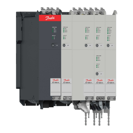
® ® ® real-time Ethernet protocols EtherCAT , Ethernet POWERLINK , and PROFINET SDM 511 SDM 511 EXM 510 SDM 512 DAM 510 ACM 510 Illustration 3: MSD Modules The system comprises: Danfoss A/S © 2019.10 AQ262450196490en-000101 / 175R1170| 23... -
Page 24: Application Examples
Some modules are available in 2 enclosure (frame) sizes with widths of 50 mm (FS1) or 100 mm (FS2) depending on the power size. Depending on the application, the system can be used exclusively in a central system, or together with Danfoss Decentral Servo Drives (ISD 510 and DSD 510) in a mixed system. -
Page 25: Maximum Number Of Modules
• PSM 510: 2 per system • DAM 510: 3 per system (Depending on the system architecture it may be possible to add more. Contact Danfoss for further information.) • SDM 511/SDM 512: Depends on the current rating and output power of the servo drive modules and the AUX current consumption during operation. - Page 26 3 Cable relief and shielding 4 Connectors: I/O, STO, relay, and Ethernet 5 Operating LEDs 6 LCP connector 7 PE screw 8 AC mains supply connector 9 Internal/external brake resistor connector Illustration 4: PSM 510 26 | Danfoss A/S © 2019.10 AQ262450196490en-000101 / 175R1170...
-
Page 27: Connectors On The Top Of Psm
50 mm). A double axis module operates 2 servo motors independently. Several feedback options are available. The SDMs are equipped with digital I/Os and Safe Torque Off (STO) and support several motor feedback encoders. Danfoss A/S © 2019.10 AQ262450196490en-000101 / 175R1170| 27... -
Page 28: Sdm 511/Sdm 512 Types
N O T I C E The Drive Configurator shows the valid configuration of servo drive variants. Only valid combinations are shown. Therefore, not all variants detailed in the type code are visible. 28 | Danfoss A/S © 2019.10 AQ262450196490en-000101 / 175R1170... -
Page 29: Components
The Servo Drive Modules SDM 511 and SDM 512 are cooled by a speed-controlled internal fan. 3.3.4 Connectors on SDM 511 This section details all connectors on the SDM 511 in enclosure sizes 1 (FS1, 50 mm) and 2 (FS2, 100 mm). Danfoss A/S © 2019.10 AQ262450196490en-000101 / 175R1170| 29... -
Page 30: Connectors On The Top Of Sdm
6 STO connector OUT 7 Relay connector Illustration 10: SDM 511, Enclosure Size 2 (FS2) 3.3.4.2 Connectors on the Bottom of SDM 511 1 Motor feedback connector 2 Motor brake and thermistor connector 30 | Danfoss A/S © 2019.10 AQ262450196490en-000101 / 175R1170... -
Page 31: Connectors On Sdm
9 STO connector OUT SDM2 10 Relay connector SDM1 11 Ethernet connector OUT SDM2 12 Relay connector SDM2 13 Ethernet connector IN SDM2 14 External encoder connector SDM2 Illustration 13: SDM 512, Enclosure Size 1 (FS1) Danfoss A/S © 2019.10 AQ262450196490en-000101 / 175R1170| 31... -
Page 32: Connectors On The Bottom Of Sdm
DAM is the abbreviation for Decentral Access Module. The DAM 510 is a central interface/gateway to the decentral servo system. It is ® ® used to connect the Danfoss VLT Integrated Servo Drives ISD 510 and VLT Decentral Servo Drives DSD 510 to the servo system via a hybrid feed-in cable. -
Page 33: Connectors On The Top Of Dam
5 Connectors: UDC, AUX, STO out, and Ethernet Illustration 15: DAM 510 3.4.2 Connectors on the Top of DAM 510 1 Ethernet connector IN 2 Ethernet connector OUT 3 STO connector IN 4 STO connector OUT Danfoss A/S © 2019.10 AQ262450196490en-000101 / 175R1170| 33... -
Page 34: Connectors On The Bottom Of Dam
The ACM 510 has a protection rating of IP20 according to IEC/EN 60529 (except connectors, which are IP00). The ACM 510 can be damaged if exposed to fluids. An example type code for the ACM 510 is: MSD510ACM510F1E00C8D6E20PLSXXXXXXXXXXXXX. 34 | Danfoss A/S © 2019.10 AQ262450196490en-000101 / 175R1170... -
Page 35: Connectors On The Top Of Acm
ACM 510 3.5.2 Connectors on the Top of ACM 510 1 Ethernet connector IN 2 Ethernet connector OUT 3 I/O connector 4 Relay connector Illustration 19: Connectors on the Top of ACM 510 Danfoss A/S © 2019.10 AQ262450196490en-000101 / 175R1170| 35... -
Page 36: Expansion Module Exm
The EXM 510 has a protection rating of IP20 according to IEC/EN 60529 (except connectors, which are IP00). The EXM 510 may be damaged if exposed to fluids. An example type code for the EXM 510 is: 36 | Danfoss A/S © 2019.10 AQ262450196490en-000101 / 175R1170... -
Page 37: Local Control Panel (Lcp)
The values in the display area differ depending on which module the LCP is connected to. The display area is activated when the module it is connected to received power from U Danfoss A/S © 2019.10 AQ262450196490en-000101 / 175R1170| 37... - Page 38 2 Temperature power card 3 Actual UDC (current) 4 Power consumption 5 Actual UDC (voltage) Illustration 21: Display Area when Connected to the Power Supply Module PSM 510 or Decentral Access Module DAM 510 38 | Danfoss A/S © 2019.10 AQ262450196490en-000101 / 175R1170...
- Page 39 Hand Auto Reset 1 Current actual value 2 Temperature power card 3 Position actual value 4 Actual velocity Illustration 22: Display Area when Connected to the Servo Drive Modules SDM 511/SDM 512 Danfoss A/S © 2019.10 AQ262450196490en-000101 / 175R1170| 39...
-
Page 40: B: Display Menu Keys
Table 5: Display Menu Keys Function Status Shows operational information. Quick Menu Allows access to parameters. Main Menu Allows access to parameters. Alarm Log Shows the last 10 alarms. 40 | Danfoss A/S © 2019.10 AQ262450196490en-000101 / 175R1170... -
Page 41: C: Navigation Keys And Indicator Lights (Leds)
Switch on Disabled and/or the PSM 510, DAM 510 or ACM 510 is in state Standby. Reset Resets the MSD 510 system module after a fault has been cleared. The reset is only possible when in Hand On mode. Danfoss A/S © 2019.10 AQ262450196490en-000101 / 175R1170| 41... -
Page 42: Cables
Loop cable for connecting the ISD 510/DSD 510 servo drives in daisy-chain format in an application. Both these cables are provided by Danfoss and are available in various lengths. See the VLT™ Servo Drive System ISD 510, DSD 510, MSD 510 Design Guide for further information. -
Page 43: Lcp Cable
Connect the real-time Ethernet fieldbus to the 1st module in the MSD 510 system using a standard Ethernet cable (not provided). Use the Ethernet loop cables provided by Danfoss to connect to the other modules in daisy-chain format. 3.9.1 Maximum Cable Lengths... -
Page 44: Wiring Of Output Filter
1 Hybrid feed-in cable 2 Hybrid loop cable 3 AC choke Illustration 25: Standard Cabling Concept for 2 Decentral Access Modules (DAM 510) 3.10 Software The software for the servo system comprises: 44 | Danfoss A/S © 2019.10 AQ262450196490en-000101 / 175R1170... -
Page 45: Fieldbus
A PLC library for TIA Portal for operating the MSD 510 devices. ® • Servo Toolbox: A Danfoss PC-based software tool for commissioning and debugging the devices. 3.11 Fieldbus The servo system has an open system architecture realized by fast Ethernet (100BASE-T) based communication. The system supports ®... - Page 46 X2 RJ45 to M23 hybrid feed-in cable to the 1st ISD 510/ DSD 510 servo drive. X3 RJ45 cable connector to the PLC (cable redundancy) or next slave. Illustration 27: EtherCAT™ Port Assignment for the Decentral Access Module (DAM 510) 46 | Danfoss A/S © 2019.10 AQ262450196490en-000101 / 175R1170...
-
Page 47: Ethernet Powerlink
There are 2 ports on the ISD 510/DSD 510 servo drives, servo drive modules SDM 511/SDM 512, the PSM 510, and the ACM 510). There are 3 ports on the DAM 510. Danfoss A/S © 2019.10 AQ262450196490en-000101 / 175R1170| 47... -
Page 48: Mechanical Installation
2. Register a complaint immediately with the carrier if there is visible transport damage. 3. Register a complaint immediately with the responsible Danfoss representative if there are visible defects or the delivery is incomplete. -
Page 49: Installation Environment
1. Provide a suitable mounting arrangement for the application. This depends on the type and weight of the modules. 2. To avoid misalignment, ensure that the backplates are perfectly level. 3. To ensure sufficient cooling, pay attention to the specified minimum space requirements. 4. Ground the modules. Danfoss A/S © 2019.10 AQ262450196490en-000101 / 175R1170| 49... -
Page 50: Drilling Templates
Drilling templates for 50 mm and 100 mm System Modules 4.7 Installation Procedure 4.7.1 Space Requirements for System Modules The modules can be mounted next to each other but require a minimum space at the top and bottom for cooling. 50 | Danfoss A/S © 2019.10 AQ262450196490en-000101 / 175R1170... - Page 51 Mechanical Installation Operating Guide | VLT® Multiaxis Servo Drive MSD 510 System [10.63] max. 100 [3.94] max. 120 [4.72] Illustration 30: Minimum Space Required at the Top and Bottom Danfoss A/S © 2019.10 AQ262450196490en-000101 / 175R1170| 51...
-
Page 52: Installation Aids And Tools Required
N O T I C E Mount the MSD 510system component with the highest output power next to the PSM 510. Mount the remaining system components in descending order of output power. 52 | Danfoss A/S © 2019.10 AQ262450196490en-000101 / 175R1170... - Page 53 3. Mount the backplates to the mounting plate in the control cabinet using M5 screws with a minimum head diameter or washer diameter of 9.5 mm. The tightening torque is 3 Nm. Danfoss A/S © 2019.10 AQ262450196490en-000101 / 175R1170| 53...
- Page 54 Mounting the Backplates in the Control Cabinet 4. Slide the module onto the carrier at the bottom of the backplate. 5. Press the 1st module onto the backlink connector at the top of the backplate. 54 | Danfoss A/S © 2019.10 AQ262450196490en-000101 / 175R1170...
- Page 55 7. Repeat steps 4, 5, and 6 for the remaining modules, ensuring that the lip at the left side of the 2nd module is inside the guiding groove at the right side of the 1st module (([1] in illustration 36). Danfoss A/S © 2019.10 AQ262450196490en-000101 / 175R1170| 55...
- Page 56 Mechanical Installation Operating Guide | VLT® Multiaxis Servo Drive MSD 510 System Illustration 36: Guiding Groove 56 | Danfoss A/S © 2019.10 AQ262450196490en-000101 / 175R1170...
-
Page 57: Electrical Installation
3-phase lines and PE line • External supply for auxiliary voltage, 24–48 V DC (PELV) • AC choke (see 5.9.1 AC Line Choke) • Observe the national statutory provisions. • The leakage current is >3.5 mA. Danfoss A/S © 2019.10 AQ262450196490en-000101 / 175R1170| 57... -
Page 58: Grounding
B RCD or RCM device on the supply side of the MSD 510 system components. N O T I C E All modules must be mounted in a control cabinet. 5.3 Grounding 5.3.1 Grounding for Electrical Safety Illustration 37: Grounding for Electrical Safety 58 | Danfoss A/S © 2019.10 AQ262450196490en-000101 / 175R1170... - Page 59 Do not ground the MSD 510 system components in daisy-chain format. Use the grounding method depicted in illustration • Keep the ground wire connections as short as possible. • Follow the wiring requirements in this manual. Danfoss A/S © 2019.10 AQ262450196490en-000101 / 175R1170| 59...
-
Page 60: Grounding For Emc-Compliant Installation
Cable Shielding on the Bottom of the System Components • Use a cable with a shielding that has a high-coverage to reduce electrical interference. • Do not use pigtails to connect the shielding. A 360° wire connection is recommended. 60 | Danfoss A/S © 2019.10 AQ262450196490en-000101 / 175R1170... -
Page 61: Mains Supply Requirements
30 A (class T or J only) PSM 510 (20 kW) gG 50 A 50 A (class T or J only) PSM 510 (30 kW) gG 63 A 80 A (class T or J only) Danfoss A/S © 2019.10 AQ262450196490en-000101 / 175R1170| 61... -
Page 62: Circuit Breakers
If the maximum current is lower, a fuse with lower current rating can be used. Rating of UL fuses: according to 125% of maximum current. Use a time delay fuse rated according to the DC voltage used. 5.6 Safety Supply Requirements Supply the STO line with a 24 V DC supply for industrial use with the following properties: 62 | Danfoss A/S © 2019.10 AQ262450196490en-000101 / 175R1170... -
Page 63: Ul Requirements
To meet the UL (Underwriters Laboratories) regulations, use a UL-approved copper cable with a minimum heat-resistance of 60 °C. Use Class 1 wire only. For PSM 510 rated 30 kW, use a maximum heat resistance of 75 °C. Control Circuit Overcurrent Protection is required. Danfoss A/S © 2019.10 AQ262450196490en-000101 / 175R1170| 63... -
Page 64: Connecting The Servo Drive Module Sdm 511/Sdm
5.8 Connecting the Servo Drive Module SDM 511/SDM 512 5.8.1 Connecting the Motor Cable Context: Axis 1:120 Axis 2:170 1 Shielded area 5 PE Illustration 40: Motor Cable for 50 mm Wide Servo Drive Modules 1 Shielded area 64 | Danfoss A/S © 2019.10 AQ262450196490en-000101 / 175R1170... - Page 65 Connecting the Motor Cable on 100 mm Wide Servo Drive Modules Procedure 1. Insert the wires into the motor connector. 2. Insert the motor connector [1]. 3. Secure and shield the motor cable using the cable tie [2]. Danfoss A/S © 2019.10 AQ262450196490en-000101 / 175R1170| 65...
-
Page 66: Connecting The Brake/Thermistor Cable
Connecting the Brake/Thermistor Cable N O T I C E Use a motor with reinforced insulation between the thermistor and the motor windings (tested with 4300 V DC and 8000 V impulse). peak 66 | Danfoss A/S © 2019.10 AQ262450196490en-000101 / 175R1170... -
Page 67: Connecting The Cables On The Top Of The Servo Drive Modules Sdm 511/Sdm
5. If I/Os are required, insert the wires into the I/O connector and insert the connector [4]. 6. If a relay is required, insert the wires into the relay connector and insert the connector [7]. Danfoss A/S © 2019.10 AQ262450196490en-000101 / 175R1170| 67... -
Page 68: Connecting The Power Supply Module Psm
PSM 510 (2 x 30 kW) 0.24 ±10% Danfoss recommends mounting the AC line choke close to the PSM 510. The maximum cable length depends on the cross-section, and the required voltage and current at the DC-link. If the AC line chokes are mounted away from the PSM 510, the maximum cable distance is 5 m. -
Page 69: Connecting 2 Psm 510 Modules To The Ac Choke
When 2 PSM 510 modules are used, the wiring between the AC line choke and each PSM 510 must be the same length within a tolerance of 0.5 m. Connect each PSM 510 to the AC choke directly. Parallel wiring is not permitted. Danfoss A/S © 2019.10 AQ262450196490en-000101 / 175R1170| 69... -
Page 70: Connecting 2 Psm 510 Modules To The Ac Choke With System Splitting
NET ST NET ST NET ST NET ST NET ST LINK/ACT LINK/ACT LINK/ACT LINK/ACT LINK/ACT LINK/ACT LINK/ACT LINK/ACT Illustration 49: Connecting 2 PSM 510 Modules to the AC Choke with System Splitting 70 | Danfoss A/S © 2019.10 AQ262450196490en-000101 / 175R1170... -
Page 71: Connecting The Cables On The Power Supply Module Psm
3 24/48 V IN connector (INPUT 24/48 V) 4 STO connector IN (STO PSM) 5 STO connector OUT (STO PSM) 6 I/O connector (I/O PSM) 7 Relay connector (REL PSM) Illustration 50: Connectors on the Top of PSM 510 Danfoss A/S © 2019.10 AQ262450196490en-000101 / 175R1170| 71... -
Page 72: Connecting The Cables On The Bottom Of The Power Supply Module Psm
B Plug the internal brake resistor connector to the internal brake connector holder [1]. 4. Connect the PSM 510 to the PE screw on the front side [3] using a PE wire. The tightening torque is 3 Nm. 72 | Danfoss A/S © 2019.10 AQ262450196490en-000101 / 175R1170... -
Page 73: Connecting The Decentral Access Module (Dam 510)
4. If required, connect the external encoder connector [5]. 5.10.2 Connecting the Feed-In Cable Context: 1 Ethernet connector 2 AUX connector 3 STO out connector 4 UDC connector Illustration 53: Connectors on the Bottom of DAM 510 Danfoss A/S © 2019.10 AQ262450196490en-000101 / 175R1170| 73... - Page 74 7 AUX– (blue, 2.5 mm 8 Ethernet/fieldbus (green, RJ45 connector) 9 PE (yellow/green, 2.5 mm /4 mm , fork lug) Illustration 54: Feed-In Cable 1 Feed-in cable PE screws 2 Bus connector 74 | Danfoss A/S © 2019.10 AQ262450196490en-000101 / 175R1170...
-
Page 75: Connecting The Auxiliary Capacitors Module Acm
3. If a relay is required, insert the wires into the relay connector (REL ACM) and insert the connector [4]. 4. Connect the ACM 510 to the PE screw on the front side using a PE wire. The tightening torque is 3 Nm. Danfoss A/S © 2019.10 AQ262450196490en-000101 / 175R1170| 75... -
Page 76: Connecting The Expansion Module Exm
1 EMC shielding plate screw 2 PE screw 3 DC cables 4 Functional earth cable 5 GND cable 6 24/48 V cable 7 Cable tie Illustration 58: Connecting the Expansion Module EXM 510 76 | Danfoss A/S © 2019.10 AQ262450196490en-000101 / 175R1170... -
Page 77: Connecting The Brake Resistor On The Psm
(see 3.2.3 Connectors on the Bottom of PSM 510). Paralleling or series of brake resistors is not permitted. Danfoss A/S © 2019.10 AQ262450196490en-000101 / 175R1170| 77... - Page 78 (see 3.2.3 Connectors on the Bottom of PSM 510). Paralleling or series of brake resistors is not permitted. 78 | Danfoss A/S © 2019.10 AQ262450196490en-000101 / 175R1170...
- Page 79 Operating Guide | VLT® Multiaxis Servo Drive MSD 510 System STATUS PSM STATUS PSM SVS ST SVS ST NET ST NET ST LINK/ACT LINK/ACT 1 Internal brake resistor Illustration 60: Connection of Brake Resistor on 2 PSM 510 Modules in Parallel Danfoss A/S © 2019.10 AQ262450196490en-000101 / 175R1170| 79...
-
Page 80: Commissioning
6.3.1 Configuration Parameter Subtool ® The Configuration Parameter subtool is the VLT Servo Toolbox subtool for configuring: • Motor data • Application data • Control data • Input/output configurations • External encoder 80 | Danfoss A/S © 2019.10 AQ262450196490en-000101 / 175R1170... -
Page 81: Drive Commissioning Subtool
The Drive Commissioning subtool is the VLT Servo Toolbox subtool for carrying out commissioning tasks, such as: • Motor feedback adjustment • Resolver amplitude calibration • Inertia measurement Illustration 62: Drive Commissioning Subtool Danfoss A/S © 2019.10 AQ262450196490en-000101 / 175R1170| 81... -
Page 82: Ethercat® Id Assignment
It is also possible to change the Node ID of a servo drive when the LCP is connected to the PSM 510 or DAM 510. This functionality is contained in parameter group 54-** ID Assignment in subgroup 54-1* Manual. 82 | Danfoss A/S © 2019.10 AQ262450196490en-000101 / 175R1170... -
Page 83: Multiple Device Id Assignment
Setting the IDs of all the servo drives connected to a Decentral Access Module (DAM 510) or Power Supply Module (PSM 510) at the same time can also be done via the LCP when it is connected to the DAM 510/PSM 510. Danfoss A/S © 2019.10 AQ262450196490en-000101 / 175R1170| 83... -
Page 84: Setting The Node Ids Of All Servo Drives And System Modules On A Decentral Access Module (Dam 510)/Power Supply Module (Psm 510) Line
IP address. The IP address and the device name are assigned by the I/O controller, when the connection to the I/O device is established. 84 | Danfoss A/S © 2019.10 AQ262450196490en-000101 / 175R1170... -
Page 85: Power-Up Time
ACM 510 UDC charging time Table 17: DC-Link (UDC) Charging Time for SDM 511 Specification Unit SDM 511 SDM 511 SDM 511 SDM 511 2.5 A 10 A 20 A UDC charging time Danfoss A/S © 2019.10 AQ262450196490en-000101 / 175R1170| 85... -
Page 86: Switching On The Msd 510 System
• TiA from V13 ® The provided function blocks conform to the PLCopen standard. Knowledge of the underlying fieldbus communication and/or the ® CANopen CiA DS 402 profile is not necessary. 86 | Danfoss A/S © 2019.10 AQ262450196490en-000101 / 175R1170... -
Page 87: Programming With Automation Studio
X20 CPU]. V4.x: Open the B&R Help Explorer and go to [Automation Software → Getting Started → Creating programs with Automation Studio → Example project for a target system with CompactFlash]. Danfoss A/S © 2019.10 AQ262450196490en-000101 / 175R1170| 87... -
Page 88: Including The Servo Motion Libraries Into An Automation Studio™ Project
The names of the POUs that target the servo drive all end with _DDS. • DDS_PSM Contains POUs defined by Danfoss (name starting with DD_) and provide the functionality for the Power Supply Module (PSM). The names of the POUs that target the PSM all end with _PSM. - Page 89 Error codes can be read using the function block DD_ReadAcmError_ACM and/or DD_ReadAcmWarning_ACM. • ACM_TraceSignals Constants for the trace signals of the Auxiliary Capacitors Module (ACM 510). Intended to be used with the function block DD_Trace_ACM. Danfoss A/S © 2019.10 AQ262450196490en-000101 / 175R1170| 89...
-
Page 90: Instantiating Axis_Ref_Dds In Automation Studio
2. To create a link to the physical PSM, link each instance of PSM_REF to 1 physical PSM. This makes it the logical representation of 1 physical PSM. Open the Logical View. Initialize each instance with its node number and the slot name it is connected to (for example, IF3). 90 | Danfoss A/S © 2019.10 AQ262450196490en-000101 / 175R1170... -
Page 91: Instantiating Dam_Ref In Automation Studio
Initialize each instance with its node number and the slot name it is connected to (for example, IF3). 6.11.9 Importing a Servo Drive into Automation Studio™ Context: N O T I C E For each physical servo drive, add 1 entry to the Physical View of Automation Studio™. Danfoss A/S © 2019.10 AQ262450196490en-000101 / 175R1170| 91... -
Page 92: Version V3.0.90
In the Select controller module window, select the servo drive in the group POWERLINK Devices. Click on Next. In the next window, enter the node number of the servo drive. Illustration 64: Adding a Servo Drive to the Project in V3.0.90 92 | Danfoss A/S © 2019.10 AQ262450196490en-000101 / 175R1170... -
Page 93: Version V4
N O T I C E For each physical Power Supply Module (PSM 510), Decentral Access Module (DAM 510), and Auxiliary Capacitors Module (ACM 510), add 1 entry to the Physical View of Automation Studio™. Danfoss A/S © 2019.10 AQ262450196490en-000101 / 175R1170| 93... -
Page 94: Version V3.0.90
In the next window, enter the node number of the PSM 510, DAM 510, or ACM 510. ® Illustration 66: 1 PSM 510, 1 DAM 510, and 2 ISD 510 Servo Drives Added to the Ethernet POWERLINK Interface in V3.0.90 94 | Danfoss A/S © 2019.10 AQ262450196490en-000101 / 175R1170... -
Page 95: Version V4
PSM: Danfoss _VLT_R_PSM DAM: Danfoss _VLT_R_DAM ACM: Danfoss _VLT_R_ACM ® Illustration 67: 1 PSM 510, 1 DAM 510, and 2 ISD 510 Servo Drives Added to the Ethernet POWERLINK Interface in V4.x Danfoss A/S © 2019.10 AQ262450196490en-000101 / 175R1170| 95... -
Page 96: I/O Configuration And I/O Mapping
It is possible to use copy and paste to apply the same I/O configuration to multiple devices of the same type. 3. Set Module supervised to off for the servo drives and the PSM/DAM/ACM. The parameter is found in the I/O configuration of the device. 96 | Danfoss A/S © 2019.10 AQ262450196490en-000101 / 175R1170... - Page 97 4. Map the inputs and outputs of the instance of the AXIS_REF_DDS function block and the physical data points of the ISD 510 servo drive (here myAxis is an instance of AXIS_REF_DDS): Danfoss A/S © 2019.10 AQ262450196490en-000101 / 175R1170| 97...
-
Page 98: Setting The Plc Cycle Time
1. Right-click [CPU → Open Software Configuration] for V3.0.90 and [CPU → Configuration → Timing] for V4.x in the Physical View. ® 2. Ensure that the PLC cycle time is the same as the Ethernet POWERLINK cycle time. 98 | Danfoss A/S © 2019.10 AQ262450196490en-000101 / 175R1170... -
Page 99: Connecting To The Plc
Beckhoff Information System (https:// infosys.beckhoff.com/). Open the information system and select [TwinCAT 2 → TwinCAT Quick Start or TwinCAT 2 → TX1200 TwinCAT PLC → TwinCAT PLC Control]. Danfoss A/S © 2019.10 AQ262450196490en-000101 / 175R1170| 99... -
Page 100: Including The Twincat® Library Into A Twincat® Project
4. Click on Open. Now the libraries are integrated into the TwinCAT PLC control project. Illustration 72: Library Manager after Including the ServoMotion Library Inside the library, the POUs are organized into folders: 100 | Danfoss A/S © 2019.10 AQ262450196490en-000101 / 175R1170... -
Page 101: Constants Within The Dds_Drive Library
The names of the POUs that target the SDM 511/SDM 512 drive modules and servo drives all end with _DDS. • DDS_PSM Contains POUs defined by Danfoss (name starting with DD_) and provide the functionality for the Power Supply Module (PSM 510). The names of the POUs that target the PSM 510 all end with _PSM. - Page 102 Error codes can be read using the function block DD_ReadAcmError_ACM and/or DD_ReadAcmWarning_ACM. • ACM_TraceSignals Constants for the trace signals of the Auxiliary Capacitors Module (ACM 510). Intended to be used with the function block DD_Trace_ACM. 102 | Danfoss A/S © 2019.10 AQ262450196490en-000101 / 175R1170...
-
Page 103: Instantiating Axis_Ref_Dds In Twincat
1. Create 1 instance of function block DAM_REF (located in folder DDS_DAM) for each Decentral Access Module that has to be controlled or monitored. 2. Repeat step 1 for additional Decentral Access Modules. Danfoss A/S © 2019.10 AQ262450196490en-000101 / 175R1170| 103... -
Page 104: Instantiating Acm_Ref In Twincat
PLC project, but with the file extension .tpy. 3. Click on Open. 6.12.10 Importing Devices to TwinCAT® Context: ® The following procedure is an example of how to import an ISD 510 servo drive to TwinCAT 104 | Danfoss A/S © 2019.10 AQ262450196490en-000101 / 175R1170... - Page 105 Operating Guide | VLT® Multiaxis Servo Drive MSD 510 System Procedure 1. Copy the ESI file Danfoss ISD 510 S.xml into the folder TwinCAT Installation Folder\Io\EtherCAT on the hard drive. This only needs to ® be done once per project. The TwinCAT System Manager automatically searches for ESI files at this location on the hard drive during start-up.
-
Page 106: Danfoss A/S © 2019.10 Aq262450196490En
Commissioning Operating Guide | VLT® Multiaxis Servo Drive MSD 510 System Illustration 75: Add a Servo Drive to the Project 106 | Danfoss A/S © 2019.10 AQ262450196490en-000101 / 175R1170... - Page 107 Add 1 entry to the EtherCAT master of the TwinCAT System Manager for each physical servo drive, PSM 510, DAM 510, and ACM 510. Add the servo drive to the correct DAM 510 line. Danfoss A/S © 2019.10 AQ262450196490en-000101 / 175R1170| 107...
-
Page 108: I/O Configuration And I/O Mapping
W A R N I N G ® Repeat steps 2–22 for Box 1 (VLT Power Supply Module) and the instance myPSM. ® Repeat steps 2–22 for Box 2 (VLT Decentral Access Module) and the instance myDAM. 108 | Danfoss A/S © 2019.10 AQ262450196490en-000101 / 175R1170... - Page 109 20. Right-click on Port via [I/O-Configuration → I/O Devices → Device1 (EtherCAT→) → Box1 (VLT→ Decentral Access Module) → Drive2 (VLT→ ISD 510 Integrated Servo Drive) → InfoData → AdsAddr] and select Change Link..Danfoss A/S © 2019.10 AQ262450196490en-000101 / 175R1170| 109...
-
Page 110: Transferring The Mappings Back To The Plc Program
To access the ® system base time, select [SYSTEM-Configuration → Real-Time Settings] in the TwinCAT System Manager. Multiples of this base time ® can then be used as EtherCAT cycle times. 110 | Danfoss A/S © 2019.10 AQ262450196490en-000101 / 175R1170... -
Page 111: Configuration As A Twincat® Nc Axis
NC axis with Yes. Then an NC task is created automatically. 6.12.15.1 I/O Configuration for Servo Drives used as NC Axes Context: ® In the TwinCAT System Manager, select a different I/O Configuration for the servo drives used as NC axes. Danfoss A/S © 2019.10 AQ262450196490en-000101 / 175R1170| 111... -
Page 112: Connecting To The Plc
Do not change the reference to the axis on a function block while it is busy. N O T I C E ® The full parameter list can be found in the VLT Servo Drive System ISD 510, DSD 510, MSD 510 Programming Guide. 112 | Danfoss A/S © 2019.10 AQ262450196490en-000101 / 175R1170... -
Page 113: Programming With Simotion Scout
SIMOTION SCOUT online help. Open ® SIMOTION SCOUT and go to [Help → Help Topics → Getting started with SIMOTION SCOUT → Create SIMOTION device and configure PG/PC communication connection]. Danfoss A/S © 2019.10 AQ262450196490en-000101 / 175R1170| 113... -
Page 114: Including The Servo Motion Libraries Into A Simotion Scout® Project
The names of the POUs that target the SDM 511/SDM 512 drive modules and servo drives all end with _DDS. • DDS_PSM Contains POUs defined by Danfoss (name starting with DD_) and provide the functionality for the Power Supply Module (PSM 510). The names of the POUs that target the PSM 510 all end with _PSM. - Page 115 Commissioning Operating Guide | VLT® Multiaxis Servo Drive MSD 510 System Illustration 81: Project Tree after Including Danfoss Servo Motion Libraries N O T I C E Do not remove or rename these libraries. Danfoss A/S © 2019.10 AQ262450196490en-000101 / 175R1170| 115...
-
Page 116: Importing Devices Into Simotion Scout
N O T I C E ® For each physical servo drive, PSM 510, DAM 510, or ACM 510, add 1 entry to the PROFINET Ethernet network in the HW Config tool. 116 | Danfoss A/S © 2019.10 AQ262450196490en-000101 / 175R1170... - Page 117 [Options → Update catalog). 6. Expand Drive Object 1 and folder Profile in the hardware catalog on the right side of the screen and drag the Danfoss Telegram to the free slot of Drive Object 1 at the bottom of the screen.
-
Page 118: Assigning Ip Configuration And Device Name
Toolbox software (see the VLT The IP address assignment is also required when using indirect communication via the VLT Servo Drive System ISD 510, DSD 510, MSD 510 Programming Guide for further information). 118 | Danfoss A/S © 2019.10 AQ262450196490en-000101 / 175R1170... - Page 119 The SDM 511/SDM 512 servo drive modules are listed under device type VLT® SDM 510. 3. Select the desired servo drive and click on OK (use the Flash button to identify the specific servo drive). Danfoss A/S © 2019.10 AQ262450196490en-000101 / 175R1170| 119...
- Page 120 5. Enter the IP address and Subnet mask and click on Assign IP configuration. Illustration 86: Entering the IP Address and Assigning the IP Configuration 6. Enter the device name that was previously selected and click on Assign Name and then Close. 120 | Danfoss A/S © 2019.10 AQ262450196490en-000101 / 175R1170...
-
Page 121: Creating A Sync Domain
One device has the role of the sync master (clock generator). All other devices are sync slaves. N O T I C E All devices that exchange data via Isochronous Real-Time (IRT) must belong to the same sync domain. Danfoss A/S © 2019.10 AQ262450196490en-000101 / 175R1170| 121... - Page 122 6. In the lower field of the Nodes section, double-click on the device that should be configured as the sync master. 7. When the Device properties window opens, select Sync master as Synchronization role and click on OK. Illustration 89: Device properties: Sync Master 122 | Danfoss A/S © 2019.10 AQ262450196490en-000101 / 175R1170...
- Page 123 15. Click on the VLT® ISD 510 IRT device. 16. Double-click on the PN-IRT-Inteface in the Module. 17. In the next window, open the IO Cycle tab and set field Assign IO device in isochronous mode to Servo. Danfoss A/S © 2019.10 AQ262450196490en-000101 / 175R1170| 123...
-
Page 124: Configuring A Topology
Commissioning Operating Guide | VLT® Multiaxis Servo Drive MSD 510 System Illustration 92: Assign IO Device in Isochronous Mode 6.14.8 Configuring a Topology Context: The topology must be configured and parameterized. 124 | Danfoss A/S © 2019.10 AQ262450196490en-000101 / 175R1170... - Page 125 ® 2. Select the path for the PROFINET I/O system or PROFINET module, for example a Danfoss MSD 510 series. 3. Select the menu [Edit → PROFINET IO → Topology]. 4. In the next window, select the Graphic view tab.
-
Page 126: Defining Send Clock And Update Time
4. In the next window, open the Sync Domain tab and in the Send clock time [ms] field, select an appropriate time for the process, for example 1.000 ms, then click on OK. ® Illustration 94: Configuring a Send Clock for PROFINET 126 | Danfoss A/S © 2019.10 AQ262450196490en-000101 / 175R1170... -
Page 127: Configuring The Update Time
6.14.10 Accessing Inputs and Outputs Context: ® SIMOTION SCOUT provides access to the device inputs and outputs of the SIMOTION device via the process image of cyclic tasks using I/O variables. Danfoss A/S © 2019.10 AQ262450196490en-000101 / 175R1170| 127... -
Page 128: Programming Using The Danfoss Vlt® Servo Motion Library
The I/O address must fit the configuration of the device in the HW Config tool. I/O variables can only be created in offline mode. 6.14.11 Programming using the Danfoss VLT® Servo Motion Library Before using data types, functions, or function blocks from libraries, the following construct must be used in the interface section: USELIB DDS_BasCam, DDS_Drive, DDS_LabCam, DDS_PSM, DDS_DAM, DDS_ACM;... -
Page 129: Instantiating Axis_Ref_Dds In Simotion Scout
Each instance of PSM_REF is the logical representation of 1 physical PSM. N O T I C E The instance of the PSM_REF structure must be created as a global variable (variable in the interface section of a unit declared with VAR_GLOBAL). Danfoss A/S © 2019.10 AQ262450196490en-000101 / 175R1170| 129... -
Page 130: Instantiating Dam_Ref In Simotion Scout
Each instance of ACM_REF is the logical representation of 1 physical ACM. N O T I C E The instance of the ACM_REF structure must be created as a global variable (variable in the interface section of a unit declared with VAR_GLOBAL). 130 | Danfoss A/S © 2019.10 AQ262450196490en-000101 / 175R1170... -
Page 131: Global Compiler Settings
3. Activate the checkbox Permit language extensions and click on OK. Illustration 98: Global Compiler Settings 6.14.17 Assigning Tasks Context: To guarantee synchronous operation, the application must use a Synchronous Task and a Peripheral Fault Task to evaluate the alarms. Danfoss A/S © 2019.10 AQ262450196490en-000101 / 175R1170| 131... - Page 132 IPOsynchronousTask in Execution System 7. In the Task configuration tab, set the Number of level overflows in the IPO cycle clock to 1 and the IPOsynchronousTask / IPO cycle clock to 50%. 132 | Danfoss A/S © 2019.10 AQ262450196490en-000101 / 175R1170...
-
Page 133: Programming Guidelines For Simotion Scout
• Do not use any UDTs, POUs, enumerations, or constants starting with the prefix iDD_. • Do not change the reference to the axis on a function block while it is busy. Danfoss A/S © 2019.10 AQ262450196490en-000101 / 175R1170| 133... -
Page 134: Vlt® Servo Toolbox Software
6.16.1 Overview ® The VLT Servo Toolbox is a standalone PC software designed by Danfoss. It is used for parameterization and diagnostics of the system modules. It is also possible to operate the devices in a non-productive environment. ® The VLT Servo Toolbox contains several subtools, which provide various functionalities. -
Page 135: Vlt® Servo Toolbox Communication
Requirements. ® 2. Download the VLT Servo Toolbox installation file from the Danfoss website. 3. Right-click on the .exe file and select Run as administrator. 4. Follow the on-screen instructions to complete the installation process. 6.16.4 VLT® Servo Toolbox Communication 6.16.4.1 Overview... - Page 136 Turn off the checksum offloading in the network driver if possible. ® Turn off the checksum validation of the specific protocol in the Wireshark preferences. Disable IPv6 on the network interfaces used for communication on the PC: 136 | Danfoss A/S © 2019.10 AQ262450196490en-000101 / 175R1170...
- Page 137 • ISD 510/DSD 510 servo drives • Power Supply Module (PSM 510) • Decentral Access Module (DAM 510) • Auxiliary Capacitors Module (ACM 510) • Servo Drive Module SDM 511/SDM 512 Danfoss A/S © 2019.10 AQ262450196490en-000101 / 175R1170| 137...
- Page 138 To reach further nodes, accessible nodes provide the capability of adding IP addresses and subnets to the PG/PC interface. The new IP addresses and subnets are then added to the Ethernet interface of the PG/PC. 138 | Danfoss A/S © 2019.10 AQ262450196490en-000101 / 175R1170...
-
Page 139: Direct Communication
5. The IP address/subnet mask is now added. N O T I C E ® If more than one Danfoss servo drive is used in the same PROFINET network, each servo drive must have a different name and IP address. - Page 140 PC software or the operating system using this network interface for other tasks, such as file and printer sharing and network discovery. Disabling these protocols reduces the number of non-relevant packets sent over the network interface and thus reduces the overall network load. 140 | Danfoss A/S © 2019.10 AQ262450196490en-000101 / 175R1170...
- Page 141 4. Uncheck all checkboxes except the one for Internet Protocol Version 4 (TCP/IPv4). 5. Disable the IPv4 Checksum offload on the network interfaces as described in 6.16.4.3.2 Network Settings for Indirect Communication. Illustration 105: Local Area Connection 2 Properties Danfoss A/S © 2019.10 AQ262450196490en-000101 / 175R1170| 141...
-
Page 142: Vlt® Servo Toolbox Commissioning
6.17 VLT® Servo Toolbox Commissioning 6.17.1 Step 1: Opening the Main Window ® The Main Window is the basis for all VLT Servo Toolbox functionalities. It consists of the following components: 142 | Danfoss A/S © 2019.10 AQ262450196490en-000101 / 175R1170... - Page 143 Tool bar Contains shortcuts for saving and loading projects, connecting to and disconnecting from networks, automatic searching for online devices, and manually adding devices. Danfoss A/S © 2019.10 AQ262450196490en-000101 / 175R1170| 143...
-
Page 144: Step 2: Connecting To Network
2. Select the fieldbus type and the network interface to connect to. 3. Click on OK to connect. 4. Verify that the connection is successful by checking the status strip at the bottom of the Main Window. 144 | Danfoss A/S © 2019.10 AQ262450196490en-000101 / 175R1170... -
Page 145: Step 3: Scanning For Devices
Technical Specification Function blocks for motion control (Formerly Part 1 and Part 2) Version 2.0 March 17, 2011. ® In addition to the PLCopen functionality, Danfoss offers further functions for the servo system. ® The following PLCopen characteristics apply to all function blocks: •... -
Page 146: Simple Programming Template
A basic sample PLC application for starting up the servo system with 1 Power Supply Module (PSM 510), 1 Decentral Access Module (DAM 510), and 2 axes is provided. The project DDS_ServoMotion_SampleProject can be downloaded from the Danfoss website. Automation Studio™: Detailed information on how to open the sample project within the ISD package in Automation Studio™... -
Page 147: Operation
Cyclic synchro- In cyclic synchronous velocity mode, the trajectory generator of the velocity is located in the control device, not nous velocity in the servo drive. mode Danfoss A/S © 2019.10 AQ262450196490en-000101 / 175R1170| 147... -
Page 148: Motion Functions
Status indicators are not reliable for safety functions. Only use them for general diagnostics during commissioning and troubleshooting. 7.2.1 Operating LEDs on SDM 511 and SDM 512 STATUS SDM SVS ST NET ST LINK/ACT Illustration 109: Operating LEDs on SDM 511 and SDM 512 148 | Danfoss A/S © 2019.10 AQ262450196490en-000101 / 175R1170... -
Page 149: Operating Leds On The Psm
Ethernet link established and active. (Link/activity status of Out) No link. 7.2.2 Operating LEDs on the PSM 510 STATUS PSM SVS ST NET ST LINK/ACT Illustration 110: Operating LEDs on PSM 510 Danfoss A/S © 2019.10 AQ262450196490en-000101 / 175R1170| 149... -
Page 150: Operating Leds On The Dam
Ethernet link established and active. (Link/activity status of Out) No link. 7.2.3 Operating LEDs on the DAM 510 STATUS DAM SVS ST NET ST LINK/ACT Illustration 111: Operating LEDs on DAM 510 150 | Danfoss A/S © 2019.10 AQ262450196490en-000101 / 175R1170... - Page 151 Ethernet link established. Flashing Ethernet link established and active. (Link/activity status of Hybrid Out) No link. LINK/ACT X3 Green Ethernet link established. Flashing Ethernet link established and active. (Link/activity status of Out) No link. Danfoss A/S © 2019.10 AQ262450196490en-000101 / 175R1170| 151...
-
Page 152: Operating Leds On The Acm
Ethernet link established. Flashing Ethernet link established and active. (Link/activity of In) No link. LINK/ACT X2 Green Ethernet link established. Flashing Ethernet link established and active. (Link/activity status of Out) No link. 152 | Danfoss A/S © 2019.10 AQ262450196490en-000101 / 175R1170... -
Page 153: Functional Safety Concept
Only perform work on electrical parts of the Danfoss system components or the ISD 510/DSD 510 servo drives after isolating the mains voltage supply and waiting for the discharge time to elapse. -
Page 154: Qualified Personnel For Working With Functional Safety
8.4 Applied Standards and Compliance Use of the STO function requires that all provisions for safety, including relevant laws, regulations, and guidelines, are satisfied. The integrated STO function complies with the following standards: 154 | Danfoss A/S © 2019.10 AQ262450196490en-000101 / 175R1170... -
Page 155: Abbreviations And Conventions
Proportion of safe failures and detected dangerous failures of a safety function or a subsystem as a percentage of all possible failures. EN IEC 61508 Safety Integrity Level EN IEC 62061 EN IEC 61800-5-2 Safe Torque Off Danfoss A/S © 2019.10 AQ262450196490en-000101 / 175R1170| 155... -
Page 156: Installation
113 shows the basic connection to be made for the STO function. A suitable safety device to switch it off is not supplied by Danfoss. The STO is activated by opening STO+ and STO–. Table 29: Activation of STO Function STO+ STO–... -
Page 157: Commissioning Test
There are 2 ways to implement the commissioning test depending on the method used to program the PLC, however the steps of the test are the same: ® • Using the Danfoss Library or the TwinCAT Library. • Bit-wise readout of the status. - Page 158 ID = 0xFF80 on all enabled servo drives. Try to run the applica- Checks that the STO Application does not run. Application does not run. tion (enable 1 or more function is working servo drives). correctly. 158 | Danfoss A/S © 2019.10 AQ262450196490en-000101 / 175R1170...
-
Page 159: Commissioning Test Using Profinet® Devices
Functional Safety Concept Operating Guide | VLT® Multiaxis Servo Drive MSD 510 System Test steps Reason for the test Expected result for Danfoss library Expected result for Twin‐ step ® library Disable STO. Check that the STO MC_ReadAxisInfo_DDS output SafeTor-... -
Page 160: Operation Of The Sto Function
Operation of the servo system can only be resumed if the test is completed successfully. If error code 0xFF81/0x11F or 0xFF85/0x120 is issued again, contact Danfoss Service. 160 | Danfoss A/S © 2019.10... -
Page 161: Fault Reset
For each axis. N O T I C E The PSM 510, DAM 510, and ACM 510 do not contribute to the dangerous failure rate of the Danfoss system and can therefore be excluded from safety-related calculations. 8.11 Maintenance, Security, and User Accessibility Maintenance: Test the STO safety function at least once per year as follows: •... - Page 162 Operating Guide | VLT® Multiaxis Servo Drive MSD 510 System User accessibility: Restrict access to the ISD 510/DSD 510 servo drives and other system components if access to them could result in safety risks. 162 | Danfoss A/S © 2019.10 AQ262450196490en-000101 / 175R1170...
-
Page 163: Diagnostics
N O T I C E If the fault cannot be eliminated by 1 of the measures listed in the troubleshooting tables, notify Danfoss Service. Have the following information available to enable Danfoss to provide help quickly and effectively: •... -
Page 164: Drive Hums And Draws High Current
Check the parameter settings. • Contact Danfoss. 9.2.1.6 Drive Screaming Possible Cause • Incorrect calibration. • Faulty current measurement. • Incorrect control loop parameters. Troubleshooting • Check the parameter settings. • Contact Danfoss. 164 | Danfoss A/S © 2019.10 AQ262450196490en-000101 / 175R1170... -
Page 165: Uneven Running
• Drive is running with incorrect parameters. Troubleshooting • Check the application. • Check the parameter settings. 9.2.1.11 Brake not Releasing Possible Cause • Defective brake control. • Incorrect mechanical brake parameters. Danfoss A/S © 2019.10 AQ262450196490en-000101 / 175R1170| 165... -
Page 166: Holding Brake Not Holding The Servo Drive
9.2.1.15 LEDs not Lighting Up Possible Cause • No power supply. Troubleshooting • Check the power supply. 9.2.1.16 Drive Protection Trips Immediately Possible Cause • Short circuit. • Incorrect control loop parameters. 166 | Danfoss A/S © 2019.10 AQ262450196490en-000101 / 175R1170... -
Page 167: Troubleshooting For The Servo System
Short on backlink. • Short on SDM 511/SDM 512 output • Short on hybrid cable. • Short on EXM 510 connector or cable. Troubleshooting • Check the cabling • Check for loose connections. Danfoss A/S © 2019.10 AQ262450196490en-000101 / 175R1170| 167... -
Page 168: Dc-Link Voltage Too High (Error 0X3210/0X103)
The sum of the servo drive current exceeds the maximum rating of the DAM 510. • The sum of the system modules' current exceeds the maximum rating of the PSM 510. • Short on backlink. 168 | Danfoss A/S © 2019.10 AQ262450196490en-000101 / 175R1170... -
Page 169: Dc Link Overpower (Error 0X2313/0X161)
Servo Drive System ISD 510, DSD 510, MSD 510 Design Guide. • Avoid simultaneous lifting of the servo drive brakes. 9.2.2.9 UAUX Overvoltage (Error 0x3292/0x133) This fault applies to the DAM 510. Possible Causes • Incorrect U supply. Danfoss A/S © 2019.10 AQ262450196490en-000101 / 175R1170| 169... -
Page 170: Uaux Undervoltage (Error 0X3294/0X135)
Check for proper grounding and loose connections. • Check the hybrid cables for short circuits or leakage currents. • Check the EXM 510 connection and cable. 9.2.2.13 Brake Resistor Error This fault applies to the PSM 510. 170 | Danfoss A/S © 2019.10 AQ262450196490en-000101 / 175R1170... -
Page 171: Brake Chopper Error
This error code is valid for PSM 510, DAM 510, ACM 510, and SDM 511/SDM 512. Table 36: No error (0x0000 / 0x0) Code Name Severity (warning/error/trip lock) Description LCP name ® PROFINET code 0x0000 No error Error No error. Danfoss A/S © 2019.10 AQ262450196490en-000101 / 175R1170| 171... -
Page 172: Generic Err (0X1000 / 0X100)
® PROFINET code lock) 0x2312 0x160 Error IIT curr ovld T current overload T current overload error. 9.3.6 High power overload (0x2313 / 0x161) This error is valid for PSM 510. 172 | Danfoss A/S © 2019.10 AQ262450196490en-000101 / 175R1170... -
Page 173: Pt Power Overload (0X2314 / 0X162)
Table 45: AUX overcurr (0x2391 / 0x125) Code Name Severity (warning/error/ Description LCP name ® PROFINET trip lock) code 0x2391 0x125 AUX overcur- Error Current on the AUX line has reached AUX overcurr rent the overcurrent limit. Danfoss A/S © 2019.10 AQ262450196490en-000101 / 175R1170| 173... -
Page 174: Aux User Limit Current (0X2393 / 0X127)
Description LCP name ® PROFINET code 0x2396 0x15C DC Overcurrent trip Error DC overcurrent trip. overcurr trip 9.3.15 Output power trip (0x2397 / 0x12B) This error is valid for PSM 510. 174 | Danfoss A/S © 2019.10 AQ262450196490en-000101 / 175R1170... -
Page 175: I2T Overload Motor (0X239B / 0X102)
LCP name ® PROFINET code lock) 0x3210 0x103 DC link overvolt- Error DC-link voltage exceeds lim- UDC overvolt 9.3.19 Overcurrent trip SW (0x3210 / 0x103) This error is valid for SDM 511/SDM 512. Danfoss A/S © 2019.10 AQ262450196490en-000101 / 175R1170| 175... -
Page 176: Dc Link Undervoltage (0X3220 / 0X104)
DC Link voltage un- Trip lock DC-link voltage unbal- DC link unbal balanced anced. 9.3.23 UAUX high voltage (0x3291 / 0x132) This error is valid for PSM 510, DAM 510, and ACM 510. 176 | Danfoss A/S © 2019.10 AQ262450196490en-000101 / 175R1170... -
Page 177: Uaux Overvoltage (0X3292 / 0X133)
PROFINET code trip lock) 0x3294 0x135 undervolt- Error below undervoltage UAUX undervolt limit. 9.3.27 UDC high voltage (0x3295 / 0x136) This error is valid for PSM 510, DAM 510, and ACM 510. Danfoss A/S © 2019.10 AQ262450196490en-000101 / 175R1170| 177... -
Page 178: Udc Low Voltage (0X3296 / 0X137)
0x3298 0x165 UDC shutdown Error Error when UDC is in shut- UDC shutdwn err error down phase. 9.3.31 UAUX shutdown error (0x3299 / 0x155) This error is valid for DAM 510. 178 | Danfoss A/S © 2019.10 AQ262450196490en-000101 / 175R1170... -
Page 179: Uaux Undervoltage Hardware (0X329A / 0X156)
Warning, error Triggered when the maximum temperature of the overtemp temperature main device component is exceeded. device PSM: Thyristor rectifier module. DAM: Maximum temperature of both high side and low side IGBTs. Danfoss A/S © 2019.10 AQ262450196490en-000101 / 175R1170| 179... -
Page 180: Too Low Temperature (0X4220 / 0X138)
Maximum temperature of pow- overtemp PC Power card er card exceeded. 9.3.39 Inrush overtemperature: DC link (0x4293 / 013C) This error is valid for PSM 510, DAM 510, and ACM 510. 180 | Danfoss A/S © 2019.10 AQ262450196490en-000101 / 175R1170... -
Page 181: Inrush Overtemperature Aux Line (0X4294 / 0X13D)
0x5112 0x109 UAUX under- Error, trip lock Undervoltage on auxiliary undervolt UAUX voltage voltage. 9.3.43 Charge switch failure voltage (0x5121 /0x158) This error is valid for PSM 510 and SDM 511/SDM 512. Danfoss A/S © 2019.10 AQ262450196490en-000101 / 175R1170| 181... -
Page 182: Ee Checksum Error (Parameter Missing) (0X5530 / 0X10A)
9.3.47 Configuration parameters limits error (0x6383 / 0x164) This error is valid for PSM 510, DAM 510, and ACM 510. 182 | Danfoss A/S © 2019.10 AQ262450196490en-000101 / 175R1170... -
Page 183: Power Eeprom Configuration Error (0X6384 / 0X166)
Brake chopper Trip lock The brake chopper current ex- brake ch over- overcurrent ceeds the limit. curr 9.3.51 Brake resistor maximum power limit (0x7181 / 0x142) This error is valid for PSM 510. Danfoss A/S © 2019.10 AQ262450196490en-000101 / 175R1170| 183... -
Page 184: Brake Resistor User Power Limit (0X7182 / 0X143)
Table 89: Internal position sensor error (0x7320 / 0x10C) Code Name Severity (warning/ Description LCP name ® PROFINET error/trip lock) code 0x7320 0x10C Internal position sensor Trip lock Absolute position sensor er- int sensor err error ror. 184 | Danfoss A/S © 2019.10 AQ262450196490en-000101 / 175R1170... -
Page 185: External Position Sensor Error (0X7380 / 0X10D)
Could not start homing method Homing meth- homing method (for example drive not in stand- od fail still). 9.3.59 Homing error distance (0x8695 / 0x111) This error is valid for SDM 511/SDM 512. Danfoss A/S © 2019.10 AQ262450196490en-000101 / 175R1170| 185... -
Page 186: Mechanical Brake Failure (0Xff01 / 0X112)
External interface power sup- ext IF pwr fail er failure ply failure. 9.3.63 Communication interrupted (0xFF10 / 0x14F) This error is valid for PSM 510, DAM 510, ACM 510, and SDM 511/SDM 512. 186 | Danfoss A/S © 2019.10 AQ262450196490en-000101 / 175R1170... -
Page 187: Fan Feedback Inconsistent (0Xff21 / 0X145)
LCP name ® PROFINET code 0xFF60 0x115 Timing violation 1 Trip lock Contact Danfoss. timing err 1 9.3.67 Timing violation 2 (0xFF61 / 0x116) This error is valid for SDM 511/SDM 512. Danfoss A/S © 2019.10 AQ262450196490en-000101 / 175R1170| 187... -
Page 188: Timing Violation 3 (0Xff62 / 0X117)
LCP name ® PROFINET code 0xFF65 0x11A Timing violation 6 Trip lock Contact Danfoss. timing err 6 9.3.72 Timing violation 7 (0xFF66 / 0x168) This error is valid for SDM 511/SDM 512. 188 | Danfoss A/S © 2019.10 AQ262450196490en-000101 / 175R1170... -
Page 189: Timing Violation 8 (0Xff67 / 0X16B)
0xFF71 0x11C Firmware: Pow- Warning, error The firmware update transfer is completed need power- er cycle needed but a power cycle is required before the cycle new firmware is active. Danfoss A/S © 2019.10 AQ262450196490en-000101 / 175R1170| 189... -
Page 190: Firmware: Update Started (0Xff72 / 0X11D)
Table 115: STO mismatch (0xFF81 / 0x11F) Code Name Severity (warning/error/ Description LCP name ® PROFINET code trip lock) 0xFF81 0x11F STO mis- Trip lock Dual diagnosis of STO voltage not STO mismatch match plausible. 190 | Danfoss A/S © 2019.10 AQ262450196490en-000101 / 175R1170... -
Page 191: P_Sto Error (0Xff85 / 0X120)
Table 119: Sign of life error (0xFF95 / 0x14E) Code Name Severity (warning/error/trip lock) Description LCP name ® PROFINET code 0xFF95 0x14E Sign of life error Error Sign of life error. SOL error Danfoss A/S © 2019.10 AQ262450196490en-000101 / 175R1170| 191... -
Page 192: Maintenance, Decommissioning, And Disposal
Every 12 months Activate STO and check the status with the and check the STO function. PLC. 10.3 Inspection during Operation 10.3.1 System Components Carry out regular inspections during operation. Check: 192 | Danfoss A/S © 2019.10 AQ262450196490en-000101 / 175R1170... -
Page 193: Repair
• The fan is not making any unusual noises. • The condition of electrical wiring and cables. 10.4 Repair Always contact the local Danfoss sales company for information about the repair policy. Danfoss A/S © 2019.10 AQ262450196490en-000101 / 175R1170| 193... -
Page 194: System Component Replacement
Unscrew the screw [4] on the EMC plate. Release the EMC plate by pressing the clip [3]. Unscrew the PE screw [1]. 4. Disconnect the I/O shielding plate on the top of the system components: 194 | Danfoss A/S © 2019.10 AQ262450196490en-000101 / 175R1170... - Page 195 Pull the I/O shielding plate upwards to remove it. 5. Release the securing clamp at the top of the module. Illustration 117: Releasing the Securing Clamp 6. Tilt the module forward and remove it from the backplate. Danfoss A/S © 2019.10 AQ262450196490en-000101 / 175R1170| 195...
-
Page 196: Fitting And Commissioning The System Components
6.6 PROFINET® ID Assignment). 6. Conduct a test run. 10.6 Cable Replacement 10.6.1 Overview Replace the cables when the rated number of bending cycles has been reached or the cable is damaged. 196 | Danfoss A/S © 2019.10 AQ262450196490en-000101 / 175R1170... -
Page 197: Feed-In Cable Replacement
8. Connect the Ethernet connector to the DAM 510. 9. Connect the PE wire to the PE screw on the DAM 510. 10. Reconnect any cables that were connected to the X3, X4, or X5 ports. Danfoss A/S © 2019.10 AQ262450196490en-000101 / 175R1170| 197... -
Page 198: Loop Cable Replacement
6. Reconnect any cables that were connected to the X3, X4, or X5 ports on both servo drives. 10.7 Fuse Replacement in Decentral Access Module (DAM 510) Context: If a single fuse blows, replace all the fuses with fuses from the same batch (fuse CAT number 5012006.25, SIBA). 198 | Danfoss A/S © 2019.10 AQ262450196490en-000101 / 175R1170... - Page 199 2. Use a screwdriver to remove the fuses and replace them with the same number of identical type fuses (see 5.4.1 Fuses). Illustration 120: Removing the Fuse 3. Replace the cover and tighten the screws [1]. The tightening torque is 2 Nm. Danfoss A/S © 2019.10 AQ262450196490en-000101 / 175R1170| 199...
-
Page 200: Fan Replacement
Servo Drive System ISD 510, DSD 510, MSD 510 Design Guide. Procedure 1. Use a screwdriver as a lever to release the fan holder. 2. Remove the fan. 3. Replace the fan with a fan of identical type. 200 | Danfoss A/S © 2019.10 AQ262450196490en-000101 / 175R1170... -
Page 201: Product Returns
10.9 Product Returns Danfoss products can be returned for disposal at no charge. A prerequisite for this is that they are free of deposits, such as oil, grease, or other types of contamination that hampers disposal. Furthermore, foreign materials or third-party components cannot be included with the returned product. -
Page 202: Specifications
Example Nameplate on the Front of the MSD 510 System Modules 11.1.2 Example Nameplate on the Side of the System Modules The following data is shown on the nameplate on the side of the system modules: 202 | Danfoss A/S © 2019.10 AQ262450196490en-000101 / 175R1170... - Page 203 6 Protection rating: IP20 according to IEC/EN 60529 (except connectors which are IP00) supply 8 Short-circuit current rating 9 Rated power Illustration 124: Example Nameplate on the Side of the System Modules for PSM 510 Danfoss A/S © 2019.10 AQ262450196490en-000101 / 175R1170| 203...
-
Page 204: Power Supply Module (Psm 510)
24/48 ±10% current consumption at 24 V DC A DC current consumption at 48 V DC A DC Output DC-link voltage V DC 565–680 ±10% DC-link capacitance µF 1800 Rated current I 204 | Danfoss A/S © 2019.10 AQ262450196490en-000101 / 175R1170... -
Page 205: Servo Drive Module (Sdm 511/Sdm 512)
SDM 511/SDM 512 incorporates internal overload protection in the following multiples of current setting: Table 122: Multiples of Current Setting Multiple of current setting Maximum trip time 20 s 8 min 2 hrs Danfoss A/S © 2019.10 AQ262450196490en-000101 / 175R1170| 205... -
Page 206: Motor Overtemperature Protection
[1.97] [0.84] [0.2] STATUS SDM1 SVS ST NET ST LINK/ACT STATUS SDM2 SVS ST NET ST LINK/ACT Ø5.2 [0.2] [10.63] Illustration 126: Dimensions of SDM 511/SDM 512, Enclosure Size 1 (FS1) 206 | Danfoss A/S © 2019.10 AQ262450196490en-000101 / 175R1170... -
Page 207: Characteristic Data Sdm 511
(at A DC 24 V DC) current consumption (at A DC 48 V DC) Output Output number of phases – Output voltage V AC Rated current I Rated power P Danfoss A/S © 2019.10 AQ262450196490en-000101 / 175R1170| 207... -
Page 208: Characteristic Data Sdm 512
Output number of phases – Output voltage V AC Rated current I 2 x 2.5 2 x 5 2 x 10 Rated power P 2 x 0.75 2 x 2.2 2 x 4 208 | Danfoss A/S © 2019.10 AQ262450196490en-000101 / 175R1170... - Page 209 Functional safety – Cooling – Integrated fan Mounting – Wall-mounted on backplate using backlink connector Number of motor connectors – Weight Dimensions 84.3 x 471 x 270 (W x H x D) Danfoss A/S © 2019.10 AQ262450196490en-000101 / 175R1170| 209...
-
Page 210: Decentral Access Module (Dam 510)
V DC 565–680 ±10% DC-link capacitance µF Maximum input current A DC V DC 24/48 ±10% current consumption at 24 V DC A DC current consumption at 48 V DC A DC 210 | Danfoss A/S © 2019.10 AQ262450196490en-000101 / 175R1170... -
Page 211: Hybrid Cable Protection
Hardware (microseconds timing range): Opens automatically if a short circuit of >36 A is present. • Hardware: A 20 A non-replaceable SMD (surface-mounted device) fuse in case the first 2 fuses fail. Danfoss A/S © 2019.10 AQ262450196490en-000101 / 175R1170| 211... -
Page 212: Auxiliary Capacitors Module (Acm 510)
48 V DC A DC Cooling – Natural convection Mounting – Wall-mounted on backplate using backlink connector Weight 3.54 Dimensions (W x H x D) 84 x 371 x 270 212 | Danfoss A/S © 2019.10 AQ262450196490en-000101 / 175R1170... -
Page 213: Expansion Module (Exm 510)
87 x 380 x 145 11.7 Connectors on the System Modules 11.7.1 Backlink Connector The backlink connector is located at the top of the backside of all the MSD 510 system modules. Danfoss A/S © 2019.10 AQ262450196490en-000101 / 175R1170| 213... - Page 214 Specifications Operating Guide | VLT® Multiaxis Servo Drive MSD 510 System Illustration 131: Pin Assignment of Backlink Connector Table 128: Pin Assignment of Backlink Connector Description 24/48 V 214 | Danfoss A/S © 2019.10 AQ262450196490en-000101 / 175R1170...
-
Page 215: Brake Connectors
The maximum length of the brake cable is 30 m (shielded). 11.7.2.2 Brake and Motor Temperature Sensor Connector on SDM 511/SDM 512 The brake connector on SDM 511/SDM 512 is used for both the mechanical brake and the temperature sensor (if present). Danfoss A/S © 2019.10 AQ262450196490en-000101 / 175R1170| 215... - Page 216 The motor temperature measurement can either be connected to the motor feedback connector (see 11.7.13 Motor Feedback Connectors) or the brake and motor temperature sensor connector on the servo drive module SDM 511/ SDM 512. The connectors cannot be connected in parallel. 216 | Danfoss A/S © 2019.10 AQ262450196490en-000101 / 175R1170...
-
Page 217: Ethernet Connectors
11.7.3 Ethernet Connectors Ethernet connectors are located on all the system modules. Illustration 134: Ethernet Connector N O T I C E Only PELV potential can be connected to the digital inputs and outputs. Danfoss A/S © 2019.10 AQ262450196490en-000101 / 175R1170| 217... -
Page 218: Ethernet Connectors On Psm 510 And Acm 510
1: TX+ According to standard 100BASE-T. X2 OUT Ethernet OUT1 2: TX– X3 OUT Ethernet OUT2 (connection to hybrid cable) 3: RX+ 4: – 5: – 6: RX– 7: – 8: – 218 | Danfoss A/S © 2019.10 AQ262450196490en-000101 / 175R1170... -
Page 219: Ethernet Connectors On Sdm 511/Sdm 512
High (logic "1") voltage: 15–48 V DC Low (logic "0") voltage: <5 V DC Maximum input signal frequency: 50 Hz Maximum input current at 48 V: 11 mA Maximum input resistance: 4.5 KΩ Danfoss A/S © 2019.10 AQ262450196490en-000101 / 175R1170| 219... -
Page 220: I/O Connector On Sdm 511/Sdm
DigInOut1 Digital input/output (switchable via software) Digital input: Nominal voltage: 0–24 V Bandwidth: ≦100 kHz Digital output: Nominal voltage: 24 V ±20% Maximum current: 150 mA Maximum switching frequency: 100 Hz 220 | Danfoss A/S © 2019.10 AQ262450196490en-000101 / 175R1170... -
Page 221: Uaux Connector
N O T I C E Only PELV potential can be connected to the digital inputs and outputs. 11.7.5 UAUX Connector The U connector is located on the Power Supply Module (PSM 510). Danfoss A/S © 2019.10 AQ262450196490en-000101 / 175R1170| 221... -
Page 222: 24/48 V Cable Cross Sections For Psm
Minimum cable cross section for UL (minimum 60 °C, Cu) 4 AWG 11.7.6 LCP Connector (M8, 6-pole) The LCP connector is located on the front of all the system modules. It used to connect the LCP directly via a cable. 222 | Danfoss A/S © 2019.10 AQ262450196490en-000101 / 175R1170... -
Page 223: Ac Mains Connector
Only PELV potential can be connected to the LCP input. 11.7.7 AC Mains Connector The AC mains connector is located on the bottom of the Power Supply Module (PSM 510). Illustration 139: AC Mains Connector Danfoss A/S © 2019.10 AQ262450196490en-000101 / 175R1170| 223... -
Page 224: Motor Connector
(minimum 60 °C, Cu) (minimum 75 °C, Cu) 11.7.8 Motor Connector The motor connectors are located on the bottom of the Servo Drive Modules (SDM 511 and SDM 512). Illustration 140: Motor Connector 224 | Danfoss A/S © 2019.10 AQ262450196490en-000101 / 175R1170... -
Page 225: Motor Cable Cross-Sections For Sdm
Servo Drive Module SDM 511: 1 relay connector • Servo Drive Module SDM 512: 2 relay connectors • Power Supply Module PSM 510: 1 relay connector • Auxiliary Capacitors Module ACM 510: 1 relay connector Danfoss A/S © 2019.10 AQ262450196490en-000101 / 175R1170| 225... -
Page 226: Relay Connector On Psm 510/Acm
Normally open, 24 V DC Conductor cross-section range: 0.2–1.5 mm (AWG 24–AWG 16) Common 11.7.9.2 Relay Connectors on SDM 511/SDM 512 Illustration 142: Relay Connector for SDM 511 Enclosure Size 1 (FS1)/SDM 512 226 | Danfoss A/S © 2019.10 AQ262450196490en-000101 / 175R1170... -
Page 227: Sto Connectors
The STO connectors are located on the Servo Drive Modules as follows: • SDM 511: 1 input and 1 output STO connector • SDM 512: 2 input and 2 output STO connectors Danfoss A/S © 2019.10 AQ262450196490en-000101 / 175R1170| 227... -
Page 228: Sto Connectors On Psm 510
Only PELV potential can be connected to the STO inputs. 11.7.10.2 STO Connectors on PSM 510 There is 1 input and 1 output STO connector on the Power Supply Module (PSM 510). 228 | Danfoss A/S © 2019.10 AQ262450196490en-000101 / 175R1170... - Page 229 Nominal current: Depends on the number of servo drives in the applica- modules. tion. STO– Used for STO input Maximum current: 1 A voltage. STO+ Conductor cross-section range: 0.2–1.5 mm (AWG 24–AWG 16) Danfoss A/S © 2019.10 AQ262450196490en-000101 / 175R1170| 229...
-
Page 230: Sto Connectors On The Dam
There is 1 input and 1 output STO connector on the top of the Decentral Access Module (DAM 510). Illustration 147: STO Output Connector on the Top of DAM 510 Illustration 148: STO Input Connector on the Top of DAM 510 230 | Danfoss A/S © 2019.10 AQ262450196490en-000101 / 175R1170... - Page 231 Nominal current: Depends on the number of servo drives in the appli- cable. cation. Maximum current: 1 A Conductor cross-section range: 0.2–1.5 mm (AWG 24–AWG 16) Plug terminal tightening torque: 0.22–0.25 Nm Danfoss A/S © 2019.10 AQ262450196490en-000101 / 175R1170| 231...
-
Page 232: Udc Connector
(AWG 24–AWG 10) Plug terminal tightening torque: 0.5–0.8 Nm 11.7.12 AUX Connector The AUX connector is located on the bottom of the Decentral Access Module (DAM 510). Illustration 151: AUX Connector 232 | Danfoss A/S © 2019.10 AQ262450196490en-000101 / 175R1170... -
Page 233: Motor Feedback Connectors
EnDat 2.2 Use a shielded feedback cable that fulfills the requirements for the used feedback type. The maximum cable length is 80 m. Illustration 152: Motor Feedback Connector on SDM 511/SDM 512 Danfoss A/S © 2019.10 AQ262450196490en-000101 / 175R1170| 233... - Page 234 To activate the internal power supply compensation, connect the 2 sense lines (SENS+ and SENS–) on the motor side to the supply (SUPPLY+ and SUPPLY–). This automatically adapts the supply voltage, depending on the cable length, and compensates the voltage drop over the feedback cable. 234 | Danfoss A/S © 2019.10 AQ262450196490en-000101 / 175R1170...
-
Page 235: External Encoder Connectors
155. E DAM SDM 512/DAM 510. Nominal current: Depends on the number of servo drives in the appli- cation. Maximum current: 150 mA (see table 155) Fulfill the following specifications: • BISS/SSI Danfoss A/S © 2019.10 AQ262450196490en-000101 / 175R1170| 235... -
Page 236: Expansion Module Connector
BiSS: Fulfills the RS485 specification. N O T I C E Only PELV potential can be connected to the external encoder. 11.7.15 Expansion Module Connector 24 V 48 V Illustration 154: Expansion Module Connector 236 | Danfoss A/S © 2019.10 AQ262450196490en-000101 / 175R1170... -
Page 237: General Specifications And Environmental Conditions For Msd 510 System
Stationary use: 5–93% (non-condensing) Ambient temperature range Operating: 5–40 °C nominal, up to 55 °C with derating (see illustration 155) Transport: –25 °C to +55 °C Storage: –25 °C to +55 °C Danfoss A/S © 2019.10 AQ262450196490en-000101 / 175R1170| 237... -
Page 238: Storage
To recondition the electrolytic capacitors, servo drives and system components not in service must be connected to a supply source once per year to allow the capacitors to charge and discharge. Otherwise the capacitors could suffer permanent damage. 238 | Danfoss A/S © 2019.10 AQ262450196490en-000101 / 175R1170... - Page 239 Error codes: STO Libraries EtherCAT® EtherCAT® ID assignment Loop cable EtherCAT® slave Loop cable connection Loop cable disconnection Ethernet connectors 218, 218, 219 Loop cable replacement Ethernet POWERLINK® Ethernet POWERLINK® ID assignment Danfoss A/S © 2019.10 AQ262450196490en-000101 / 175R1170| 239...
- Page 240 PSM_REF 90, 103 VLT® Servo Toolbox: Installation VLT® Servo Toolbox: PC requirements Qualified personnel Warnings for electrical installation Recycling Relay connector Repair Resources for servo system Safety during installation Safety instructions 240 | Danfoss A/S © 2019.10 AQ262450196490en-000101 / 175R1170...
- Page 241 A direct constant voltage. Decentral Servo Drive EPSG Ethernet POWERLINK Standardization Group. EtherCAT Technology Group ® EtherCAT (Ethernet for Control Automation Technology) is an open high- EtherCAT performance Ethernet-based fieldbus system. EtherCAT is registered trade- Danfoss A/S © 2019.10 AQ262450196490en-000101 / 175R1170| 241...
- Page 242 Rotating shaft on the A side of the servo motor, typically without a key groove. Multi-turn encoder Describes an absolute encoder, in which the absolute position remains known after several revolutions. 242 | Danfoss A/S © 2019.10 AQ262450196490en-000101 / 175R1170...
- Page 243 Module (DAM 510), and the optional Auxiliary Capacitors Module (ACM 510). ® TwinCAT is a registered trademark of and licensed by Beckhoff Automation TwinCAT GmbH, Germany. It is the integrated software development environment for controllers from Beckhoff. Danfoss A/S © 2019.10 AQ262450196490en-000101 / 175R1170| 243...
- Page 244 A pc software tool used for parameter setting and diagnostics of VLT Servo Servo Toolbox Drive systems ® Wireshark is a network protocol analyzer released under the GNU General Wireshark Public License version 2. 244 | Danfoss A/S © 2019.10 AQ262450196490en-000101 / 175R1170...
- Page 245 Operating Guide | VLT® Multiaxis Servo Drive MSD 510 System VLT Servo Drive Systems Glossary Danfoss A/S © 2019.10 AQ262450196490en-000101 / 175R1170| 245...
-
Page 246: Aq262450196490En-000101
Danfoss can accept no responsibility for possible errors in catalogues, brochures and other printed material. Danfoss reserves the right to alter its products without notice. This also applies to products already on order provided that such alterations can be made without subsequential changes being necessary in specifications already agreed. All trademarks in this material are property of the respective companies.
Need help?
Do you have a question about the VLT MSD 510 and is the answer not in the manual?
Questions and answers