Sign In
Upload
Manuals
Brands
Danfoss Manuals
DC Drives
VLT MSD 510
Danfoss VLT MSD 510 Manuals
Manuals and User Guides for Danfoss VLT MSD 510. We have
1
Danfoss VLT MSD 510 manual available for free PDF download: Operating Manual
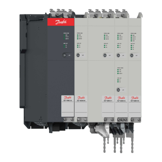
Danfoss VLT MSD 510 Operating Manual (246 pages)
Multiaxis Servo Drive
Brand:
Danfoss
| Category:
DC Drives
| Size: 13.01 MB
Table of Contents
Table of Contents
3
1 Introduction
14
Purpose of the Operating Guide
14
Additional Resources
14
Copyright
14
Approvals and Certifications
15
Areas of Application
16
Software
16
Terminology
17
2 Safety
18
Safety Symbols
18
Safety Instructions and Precautions
18
Operational Safety
19
Important Safety Warnings
19
Qualified Personnel
21
Due Diligence
21
Intended Use
21
Prohibited Application Areas
22
Forseeable Misuse
22
Service and Support
22
3 System Description
23
Overview of the VLT® Multiaxis Servo Drive System MSD
23
Application Examples
24
Maximum Number of Modules
25
Power Supply Module PSM
25
Overview
25
Connectors on the Top of PSM
27
Connectors on the Bottom of PSM
27
Servo Drive Module SDM 511/SDM
27
Overview
27
SDM 511/SDM 512 Types
28
Components
29
Cooling
29
Connectors on SDM
29
Connectors on the Top of SDM
30
Connectors on the Bottom of SDM
30
Connectors on SDM
31
Connectors on the Top of SDM
31
Connectors on the Bottom of SDM
32
Decentral Access Module DAM
32
Overview
32
Connectors on the Top of DAM
33
Connectors on the Bottom of DAM
34
Auxiliary Capacitors Module ACM
34
Overview
34
Connectors on the Top of ACM
35
Expansion Module EXM
36
Local Control Panel (LCP)
37
Overview of the Local Control Panel
37
Layout of the Local Control Panel
37
A: Display Area
37
B: Display Menu Keys
40
C: Navigation Keys and Indicator Lights (Leds)
41
D: Operation Keys and Reset
41
Cables
42
Hybrid Cable
42
Ethernet Cable
42
LCP Cable
43
Cable Layout and Routing
43
Maximum Cable Lengths
43
Wiring of Output Filter
44
Standard Cabling Concept for 2 Decentral Access Modules (DAM 510)
44
Software
44
Fieldbus
45
Ethercat
45
Ethernet POWERLINK
47
Profinet
47
4 Mechanical Installation
48
Items Supplied
48
Transport
48
Inspection on Receipt
48
Safety Measures During Installation
48
Installation Environment
49
System Components
49
Preparation for Installation
49
System Modules
49
Drilling Templates
50
Installation Procedure
50
Space Requirements for System Modules
50
Installation Aids and Tools Required
52
Fitting Instructions for System Modules
52
5 Electrical Installation
57
Warnings for Electrical Installation
57
Electrical Environmental Conditions
57
Grounding
58
Grounding for Electrical Safety
58
Grounding for EMC-Compliant Installation
60
Mains Supply Requirements
61
Fuses
61
Circuit Breakers
62
Auxiliary Supply Requirements
62
Fuses
62
Safety Supply Requirements
62
UL Requirements
63
Connecting the Servo Drive Module SDM 511/SDM
64
Connecting the Motor Cable
64
Connecting the Brake/Thermistor Cable
66
Connecting the Cables on the Top of the Servo Drive Modules SDM 511/SDM
67
Connecting the Power Supply Module PSM
68
AC Line Choke
68
Connecting 1 PSM 510 to the AC Choke
68
Connecting 2 PSM 510 Modules to the AC Choke
69
Connecting 2 PSM 510 Modules to the AC Choke with System Splitting
70
Connecting the Cables on the Power Supply Module PSM
71
Connecting the Cables on the Top of the Power Supply Module PSM
71
Connecting the Cables on the Bottom of the Power Supply Module PSM
72
Connecting the Decentral Access Module (DAM 510)
73
Connecting the Cables on the Top of the Decentral Access Module DAM
73
Connecting the Feed-In Cable
73
Connecting the Auxiliary Capacitors Module ACM
75
Connecting the Expansion Module EXM
76
Connecting the Brake Resistor on the PSM
77
6 Commissioning
80
Warnings for Commissioning
80
Pre-Commissioning Checklist
80
SDM 511/SDM 512 Configuration Parameter and Drive Commissioning
80
Configuration Parameter Subtool
80
Drive Commissioning Subtool
81
Ethercat® ID Assignment
82
Ethernet POWERLINK® ID Assignment
82
Overview
82
Single Device ID Assignment
82
Setting the Node ID Directly on a Servo Drive or on the System Modules
82
Setting the Node ID for a Single Servo Drive Via the Power Supply Module (PSM 510) or Decentral Access Module (DAM 510) Via the LCP
82
Multiple Device ID Assignment
83
Setting the Node Ids of All Servo Drives and System Modules on a Decentral Access Module (DAM 510)/Power Supply Module (PSM 510) Line
84
PROFINET® ID Assignment
84
Power-Up Time
85
System Module Charging Time
85
Switching on the MSD 510 System
86
Procedure for Switching on the MSD 510 System
86
Libraries
86
Programming with Automation Studio
87
Requirements for Programming with Automation Studio
87
Creating an Automation Studio™ Project
87
Including the Servo Motion Libraries into an Automation Studio™ Project
88
Constants Within the Dds_Drive Library
88
Instantiating AXIS_REF_DDS in Automation Studio
90
Instantiating PSM_REF in Automation Studio
90
Instantiating DAM_REF in Automation Studio
91
Instantiating ACM_REF in Automation Studio
91
Importing a Servo Drive into Automation Studio
91
Version V3.0.90
92
Version V4
93
Importing PSM 510, DAM 510 and ACM 510 into Automation Studio
93
Version V3.0.90
94
Version V4
95
I/O Configuration and I/O Mapping
96
Setting the PLC Cycle Time
98
Connecting to the PLC
99
Programming with Twincat
99
Requirements for Programming with Twincat
99
Creating a Twincat® Project
99
Including the Twincat® Library into a Twincat® Project
100
Constants Within the Dds_Drive Library
101
Instantiating AXIS_REF_DDS in Twincat
103
Instantiating PSM_REF in Twincat
103
Instantiating DAM_REF in Twincat
103
Instantiating ACM_REF in Twincat
104
Adding a PLC Project to Twincat® System Manager
104
Importing Devices to Twincat
104
Danfoss A/S © 2019.10 Aq262450196490En
106
I/O Configuration and I/O Mapping
108
Attaching the Input and Output Variables to the Physical Data Points
108
Transferring the Mappings Back to the PLC Program
110
Setting the PLC Cycle Time in Twincat® PLC Control
110
Configuration as a Twincat® NC Axis
111
I/O Configuration for Servo Drives Used as NC Axes
111
Connecting to the PLC
112
Programming Guidelines for Automation Studio™ and Twincat
112
Programming with SIMOTION SCOUT
113
Requirements for Programming with SIMOTION SCOUT
113
Connecting to the PLC
113
Creating a SIMOTION SCOUT® Project
113
Including the Servo Motion Libraries into a SIMOTION SCOUT® Project
114
Importing Devices into SIMOTION SCOUT
116
Assigning IP Configuration and Device Name
118
Creating a Sync Domain
121
Configuring a Topology
124
Defining Send Clock and Update Time
126
Configuring the Send Clock Time
126
Configuring the Update Time
127
Accessing Inputs and Outputs
127
Programming Using the Danfoss VLT® Servo Motion Library
128
Instantiating AXIS_REF_DDS in SIMOTION SCOUT
129
Instantiating PSM_REF in SIMOTION SCOUT
129
Instantiating DAM_REF in SIMOTION SCOUT
130
Instantiating ACM_REF in SIMOTION SCOUT
130
Global Compiler Settings
131
Assigning Tasks
131
Programming Guidelines for SIMOTION SCOUT
133
VLT® Servo Toolbox Software
134
Overview
134
System Requirements
134
Installing the VLT® Servo Toolbox Software
134
VLT® Servo Toolbox Communication
135
Overview
135
Firewall
135
Indirect Communication
135
Direct Communication
139
VLT® Servo Toolbox Commissioning
142
Step 1: Opening the Main Window
142
Step 2: Connecting to Network
144
Step 3: Scanning for Devices
145
Motion Library
145
Function Blocks
145
Simple Programming Template
146
7 Operation
147
Operating Modes
147
Supported Operating Modes
147
Motion Functions
148
Operating Status Indicators
148
Operating Leds on SDM 511 and SDM
148
Operating Leds on the PSM
149
Operating Leds on the DAM
150
Operating Leds on the ACM
152
8 Functional Safety Concept
153
Functional Description
153
Safety Precautions
153
Qualified Personnel for Working with Functional Safety
154
Applied Standards and Compliance
154
Abbreviations and Conventions
155
Installation
156
Protective Measures
156
Application Example
156
Commissioning Test
157
Commissioning Test Using Libraries
157
Commissioning Test Using PROFINET® Devices
159
Operation of the STO Function
160
Error Codes
160
Fault Reset
161
Functional Safety Characteristic Data
161
Maintenance, Security, and User Accessibility
161
9 Diagnostics
163
Faults
163
Troubleshooting
163
Troubleshooting for the Servo Drive Modules SDM 511/SDM
163
Drive Not Running/Starting Slowly
163
Drive Hums and Draws High Current
164
Drive Stops Suddenly and Restart Is Not Possible
164
Motor Rotating in Wrong Direction
164
Motor Not Generating Expected Torque
164
Drive Screaming
164
Uneven Running
165
Vibration
165
Unusual Running Noises
165
Drive Speed Drops Sharply under Load
165
Brake Not Releasing
165
Holding Brake Not Holding the Servo Drive
166
Delayed Brake Engagement
166
Noises When Power-Off Brake Is Engaged
166
Leds Not Lighting up
166
Drive Protection Trips Immediately
166
Troubleshooting for the Servo System
167
LCP Display Is Dark/Not Functioning
167
Open Power Fuses or Circuit Breaker Trip
167
DC-Link Voltage too High (Error 0X3210/0X103)
168
DC-Link Voltage too Low (Error 0X3220/0X104)
168
DC-Link Overcurrent (Error 0X2396/0X15C)
168
DC Link Overpower (Error 0X2313/0X161)
169
PT Power Overload (Error 0X2314/0X162)
169
UAUX Overcurrent (Error 0X2391/0X125)
169
UAUX Overvoltage (Error 0X3292/0X133)
169
UAUX Undervoltage (Error 0X3294/0X135)
170
Mains Phase Loss (Error 0X3130/0X12F)
170
Grounding Fault
170
Brake Resistor Error
170
Brake Chopper Error
171
Internal Fan Error
171
Error Codes
171
No Error (0X0000 / 0X0)
171
Generic Err (0X1000 / 0X100)
172
Overcurrent on Output (0X2310 / 0X101)
172
High Current Overload (0X2311 / 0X15F)
172
I2T Current Overload (0X2312 / 0X160)
172
High Power Overload (0X2313 / 0X161)
172
PT Power Overload (0X2314 / 0X162)
173
Short Circuit (0X2320 / 0X163)
173
Earth Leakage (0X2330 / 0X151)
173
AUX Overcurrent (0X2391 / 0X125)
173
AUX User Limit Current (0X2393 / 0X127)
174
AUX User Limit Current Warning (0X2394 / 0X128)
174
AUX Fuse Failure (0X2395 / 0X129)
174
DC Overcurrent Trip (0X2396 / 0X15C)
174
Output Power Trip (0X2397 / 0X12B)
174
I2T Overload Motor (0X239B / 0X102)
175
Mains Phase Loss (0X3130 / 0X12F)
175
DC Link Overvoltage (0X3210 / 0X103)
175
Overcurrent Trip SW (0X3210 / 0X103)
175
DC Link Undervoltage (0X3220 / 0X104)
176
UDC Charging Error (0X3230 / 0X152)
176
DC Link Voltage Unbalanced (0X3280 / 0X153)
176
UAUX High Voltage (0X3291 / 0X132)
176
UAUX Overvoltage (0X3292 / 0X133)
177
UAUX Low Voltage (0X3293 / 0X134)
177
UAUX Undervoltage (0X3294 / 0X135)
177
UDC High Voltage (0X3295 / 0X136)
177
UDC Low Voltage (0X3296 / 0X137)
178
UAUX Charging Error (0X3297 / 0X154)
178
UDC Shutdown Error (0X3298 / 0X165)
178
UAUX Shutdown Error (0X3299 / 0X155)
178
UAUX Undervoltage Hardware (0X329A / 0X156)
179
Automated Fault Reset Failure (0X329B / 0X168)
179
Device Overtemperature (0X4210 / 0X157)
179
Too Low Temperature (0X4220 / 0X138)
180
Overtemperature: Power Module (0X4290 / 0X105)
180
Overtemperature: Control Card (0X4291 / 0X106)
180
Overtemperature: Power Card (0X4292 / 0X107)
180
Inrush Overtemperature: DC Link (0X4293 / 013C)
180
Inrush Overtemperature AUX Line (0X4294 / 0X13D)
181
Overtemperature: Motor (0X4310 / 0X108)
181
UAUX Undervoltage (0X5112 / 0X109)
181
Charge Switch Failure Voltage (0X5121 /0X158)
181
EE Checksum Error (Parameter Missing) (0X5530 / 0X10A)
182
Parameter Error (0X6320 / 0X10B)
182
Conf Par Ver (0X6382 / 0X15D)
182
Configuration Parameters Limits Error (0X6383 / 0X164)
182
Power Eeprom Configuration Error (0X6384 / 0X166)
183
Brake Chopper Failure (0X7111 / 0X141)
183
Brake Chopper Overcurrent (0X7112 / 0X167)
183
Brake Resistor Maximum Power Limit (0X7181 / 0X142)
183
Brake Resistor User Power Limit (0X7182 / 0X143)
184
Brake Mains Voltage too High (0X7183 / 0X159)
184
Internal Position Sensor Error (0X7320 / 0X10C)
184
External Position Sensor Error (0X7380 / 0X10D)
185
Following Error (0X8611 / 0X10E)
185
Homing Error on Entering Homing Mode (0X8693 / 0X10F)
185
Homing Error on Start Homing Method (0X8694 / 0X110)
185
Homing Error Distance (0X8695 / 0X111)
185
Mechanical Brake Failure (0Xff01 / 0X112)
186
Short Circuit in Mechanical Brake Control (0Xff02 / 0X113)
186
External Interface Power Failure (0Xff0A / 0X114)
186
Communication Interrupted (0Xff10 / 0X14F)
186
Fan Feedback Inconsistent (0Xff21 / 0X145)
187
Fan Lifetime Critical (0Xff22 / 0X15A)
187
Timing Violation 1 (0Xff60 / 0X115)
187
Timing Violation 2 (0Xff61 / 0X116)
187
Timing Violation 3 (0Xff62 / 0X117)
188
Timing Violation 4 (0Xff63 / 0X118)
188
Timing Violation 5 (0Xff64 / 0X119)
188
Timing Violation 6 (0Xff65 / 0X11A)
188
Timing Violation 7 (0Xff66 / 0X168)
188
Timing Violation 8 (0Xff67 / 0X16B)
189
Timing Violation 9 (0Xff68 / 0X16C)
189
Firmware: Package Description Mismatch (0Xff70 / 0X11B)
189
Firmware: Power Cycle Needed (0Xff71 / 0X11C)
189
Firmware: Update Started (0Xff72 / 0X11D)
190
Firmware: Update Invalid (0Xff73 / 0X15B)
190
STO Active While Drive Enabled (0Xff80 / 0X11E)
190
STO Mismatch (0Xff81 / 0X11F)
190
P_STO Error (0Xff85 / 0X120)
191
Guide Value Reversed (0Xff90 / 0X121)
191
Guide Value Implausible (0Xff91 / 0X122)
191
Sign of Life Error (0Xff95 / 0X14E)
191
10 Maintenance, Decommissioning, and Disposal
192
Warnings
192
Maintenance Tasks
192
Inspection During Operation
192
System Components
192
Repair
193
System Component Replacement
194
Dismounting the System Components
194
Fitting and Commissioning the System Components
196
Cable Replacement
196
Overview
196
Feed-In Cable Replacement
197
Disconnecting the Feed-In Cable
197
Replacing the Feed-In Cable
197
Connecting the Feed-In Cable
197
Loop Cable Replacement
198
Disconnecting the Loop Cable
198
Replacing the Loop Cable
198
Connecting the Loop Cable
198
Fuse Replacement in Decentral Access Module (DAM 510)
198
Fan Replacement
200
Product Returns
201
Recycling
201
Disposal
201
11 Specifications
202
Nameplates
202
Example Nameplate on the Front of the System Modules
202
Example Nameplate on the Side of the System Modules
202
Power Supply Module (PSM 510)
204
Dimensions of PSM 510
204
Servo Drive Module (SDM 511/SDM 512)
205
Motor Overload Protection
205
Motor Overtemperature Protection
206
Dimensions
206
Characteristic Data SDM 511
207
Characteristic Data SDM 512
208
Decentral Access Module (DAM 510)
210
Dimensions of DAM 510
210
Hybrid Cable Protection
211
Auxiliary Capacitors Module (ACM 510)
212
Dimensions
212
Characteristic Data for ACM
212
Expansion Module (EXM 510)
213
Dimensions
213
Connectors on the System Modules
213
Backlink Connector
213
Brake Connectors
215
Ethernet Connectors
217
Ethernet Connectors on PSM 510 and ACM 510
218
Ethernet Connectors on SDM 511/SDM 512
219
I/O Connector on SDM 511/SDM
220
UAUX Connector
221
24/48 V Cable Cross Sections for PSM
222
LCP Connector (M8, 6-Pole)
222
AC Mains Connector
223
Motor Connector
224
Mains Cable Cross-Sections for PSM 510
224
Motor Cable Cross-Sections for SDM
225
Relay Connector
225
Relay Connector on PSM 510/ACM
226
Relay Connectors on SDM 511/SDM
226
STO Connectors
227
STO Connectors on SDM 511 and SDM
227
STO Connectors on PSM 510
228
STO Connectors on the DAM
230
UDC Connector
232
AUX Connector
232
Motor Feedback Connectors
233
External Encoder Connectors
235
Expansion Module Connector
236
General Specifications and Environmental Conditions for MSD 510 System
237
Storage
238
Aq262450196490En-000101
246
Advertisement
Advertisement
Related Products
Danfoss VLT BACnet/IP MCA 125
Danfoss VLT CANopen MCA 105
Danfoss MCA 122 Modbus TCP
Danfoss VLT Brake Resistor MCE 101
Danfoss VLT MCB 115
Danfoss MCD 500
Danfoss VLT5000FLUX
Danfoss VLT HVACDrive
Danfoss VLT AutomationDrive
Danfoss VLT HVAC Drive FC 102
Danfoss Categories
Controller
DC Drives
Thermostat
Control Unit
Water Pump
More Danfoss Manuals
Login
Sign In
OR
Sign in with Facebook
Sign in with Google
Upload manual
Upload from disk
Upload from URL