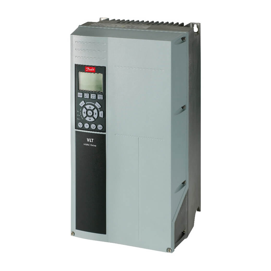
Danfoss VLT FC Series Instructions Manual
Add on for ethernet/ip
Hide thumbs
Also See for VLT FC Series:
- Installation manual ,
- Service manual (370 pages) ,
- Operating instructions manual (64 pages)
Advertisement
Quick Links
Advertisement

Summary of Contents for Danfoss VLT FC Series
- Page 1 MAKING MODERN LIVING POSSIBLE Instruction VLT® FC Series Add On Instruction for MCA 121 EtherNet/IP...
-
Page 2: Intended Use
The purpose of this document is to go over the integration of a FC Drive and EtherNet/IP Option Card, MCA 121 into the Logix5000 control Systems (ControlLogix, CompactLogix, FlexLogix). To do this we will go over how to use the Danfoss supplied Add-On Instructions (AOIs). - Page 3 IP settings are being set via a DIP switches, BOOTP or DHCP Server see the EtherNet/IP manual MG.90.Jx.yy for more information. Parameter Description Setting 12-00 IP Address Assignment [0] Manual 12-01 IP Address e.g. 192.168.1.10 12-02 Subnet Mask e.g. 255.255.255.000 ® MI3xxxxxxx - VLT is a registered Danfoss trademark...
- Page 4 [1614] Motor Current 12-22 [3] [1614] Motor Current 12-22 [4] [1690] Alarm Word 12-22 [5] [1690] Alarm Word 12-22 [6] [1692] Warning Word 12-22 [7] [1692] Warning Word ® MIxxxxxx - VLT is a registered Danfoss trademark...
-
Page 5: Importing The Add-On Instruction
Select the Add-On Instruction file “VLT”, located where you stored the file. The file selection window is illustrated in Figure 1 Import Add-On Instruct Figure 2 select Add-On Instruction file Press the “Import…” button and the Add‐On Instruction will be imported to the RXLogix 5000 tool. ® MI3xxxxxxx - VLT is a registered Danfoss trademark... - Page 6 Add-On Instruction can be imported by pressing the “OK” Button. No further settings are required in this menu. Verify the Add-On Instruction is available under the “Add-On Instruction” menu and looks similar to Figure 4. And that the name is the same. ® MIxxxxxx - VLT is a registered Danfoss trademark...
- Page 7 4.0 Configure the PLC’s I/O. Previous to the following steps, the EDS file for the Danfoss FC drives has to be installed. Please see MG.90.Jx.yy for detailed information. Add the VLT FC to the EtherNet/IP scanner module. When the module is added, the following module dialog will appear...
- Page 8 5.0 Setting up the Add-On Instruction. The Danfoss Add-On Instruction can be copied to the PLC’s rung. This is done by opening the Add-On Instruction folder and drag and drop the VLT AOI into a rung in the PLC. When the AOI has been placed the GUI should look like in figure 7.
- Page 9 Alarm Boolean If true (1) the drive has a active alarm Real Main Actual Value. Actual motor speed in % of nominal motor speed Current Real Motor current in Amps ® MI3xxxxxxx - VLT is a registered Danfoss trademark...
- Page 10 RUN bit to true and setting the MRV to a value between 0.0 and 100.0%. If MRV is set to a negative value the motor will run in CCW (If parameter 4-10 is set to “Both directions”) ® MIxxxxxx - VLT is a registered Danfoss trademark...
- Page 11 www.danfoss.com/drives 130R0xyz MIyyuxxxx Rev. 2013-09-20 ...


Need help?
Do you have a question about the VLT FC Series and is the answer not in the manual?
Questions and answers