Table of Contents
Advertisement
Quick Links
Download this manual
See also:
User Manual
Advertisement
Chapters
Table of Contents

Related Manuals for Keithley 4200-SCS


Summary of Contents for Keithley 4200-SCS
- Page 1 Model 4200-SCS Semiconductor Characterization System Reference Manual 4200-901-01 Rev. S / May 2017 *P4200-901-01S* 4200-901-01S...
- Page 3 KTE Interactive Version 9.1SP2 © 2017, Keithley Instruments All rights reserved. Any unauthorized reproduction, photocopy, or use of the information herein, in whole or in part, without the prior written approval of Keithley Instruments. is strictly prohibited. ® ® , TSP-Link , and TSP-Net are trademarks of Keithley Instruments.
- Page 4 This page left blank intentionally.
- Page 5 Keithley Instruments products are designed for use with electrical signals that are measurement, control, and data I/O connections, with low transient overvoltages, and must not be directly connected to mains voltage or to voltage sources with high transient overvoltages.
- Page 6 (note that selected parts should be purchased only through Keithley Instruments to maintain accuracy and functionality of the product). If you are unsure about the applicability of a replacement component, call a Keithley Instruments office for information.
-
Page 7: Table Of Contents
Table of Contents Model 4200-SCS Reference Manual Table of Contents Section Topic Page Introduction ....................1-1 Introduction ....................... 1-2 Embedded PC policy..................1-2 Model 4200-SCS system overview ..............1-2 Software features..................1-4 Hardware features and capabilities ............1-4 Model 4200-SCS documentation overview ............ - Page 8 Table of Contents Model 4200-SCS Reference Manual Connections and Configuration ............... 4-1 Introduction ....................... 4-3 Basic source-measure connections ..............4-3 Connection considerations ................. 4-4 SMU connections ..................4-7 PreAmp connections .................. 4-8 Using the ground unit ................4-10 SMU circuit COMMON connections ............
- Page 9 ..........6-287 Formulator function reference..............6-292 Subsite cycling ....................6-317 Overview....................6-317 Stress/Measure Mode................6-321 Storing test results in exportable Keithley Data File (KDF) format ....6-326 Customizing KITE ..................6-336 Customizing workspace options ............. 6-336 Customizing directory options..............6-340 Customizing graph defaults ..............
- Page 10 8-213 LPTLib and KITE interaction via UTMs ............8-220 Cross-platform LPTLib compatibility.............. 8-220 S400/S600 functions not supported by the Model 4200-SCS ....8-226 Moving user libraries: 4200-SCS to S400..........8-227 Moving user libraries: Model 4200-SCS to a Model S600/S630..... 8-230 Keithley External Control Interface (KXCI) ..........
- Page 11 ..............10-7 BIOS settings ....................10-9 Default video settings..................10-9 Driving an external monitor from a 4200-SCS with an integrated FPD ..10-9 Placing KITE or KXCI in the Windows startup menu ........10-10 System-level backup and restore software ........... 10-10 Acronis True Image OEM ...............
- Page 12 .................. 12-33 vdsid_pulseiv_demo ................12-35 vgsid_pulseiv_demo ................12-35 scopeshot_pulseiv_demo ............... 12-35 KPulse (for Keithley Pulse Generator Cards) ........13-1 KScope (for Models 4200-SCP2 and 4200-SCP2HR) ......14-1 KScope graphical user interface ..............14-2 Configure Input settings................14-3 Configure Trigger settings ................
- Page 13 Model 4200-SCS Reference Manual Table of Contents Multi-Frequency C-V measurements (Model 4210-CVU) ....15-1 Introduction ..................... 15-5 4210-CVU card ....................15-5 Measurement overview................15-5 Measurement functions ................15-6 Test signal....................15-7 DC bias function and sweep characteristics ..........15-7 Force-measure timing................
- Page 14 Table of Contents Model 4200-SCS Reference Manual Models 4220-PGU, 4225-PMU, and 4225-RPM ........16-1 Supplied accessories ..................16-4 Models 4220-PGU and 4225-PMU ..............16-4 Overview....................16-4 Pulse modes ..................... 16-6 Standard pulse mode output and timing characteristics ......16-7 Segment ARB characteristics ..............
- Page 15 ......... B-15 Switch matrix control example ................ B-21 Matrixulib user library reference..............B-22 ConnectPins user module................. B-22 Using a Keithley Instruments Model 590 CV Analyzer ...... C-1 concepts..................... C-2 C-V measurement basics ................C-2 Capacitance measurement tests ..............C-3 Connections....................C-3 Cable compensation ...................
- Page 16 C-V sweep ....................D-7 hp4284ulib User Library Reference ..............D-9 CvSweep4284 User Module ............... D-9 Cmeas4284 User Module ................. D-11 Using a Keithley Model 82 C-V System ..........E-1 concepts..................... E-3 Capacitance measurement tests ..............E-3 Cable compensation ................... E-6 Connections ......................
- Page 17 Model 4200-SCS Reference Manual Table of Contents Using a Probe Station ................G-1 Prober control overview ................... G-2 Example test execution sequence: probesites project....... G-4 Example test execution sequence: probesubsites project......G-5 Understanding site coordinate information............G-6 Reference site (die) ...................
- Page 18 Table of Contents Model 4200-SCS Reference Manual KCON ....................... K-30 KITE......................K-32 Commands and error symbols ................ K-33 Signatone CM500 Prober ................L-1 Required probe station software ............... L-2 Software versions ..................L-2 Probe station configuration ................L-2 Modifying the prober configuration file............
- Page 19 Model 4200-SCS Reference Manual Table of Contents Open and modify the “RdsonAvg” user module........O-17 Save, compile, and build the modified library .......... O-19 Add a new UTM to the “ivswitch” project ..........O-20 Test description..................O-22 Index ..........................I-1 4200-901-01 Rev.
- Page 20 Table of Contents Model 4200-SCS Reference Manual This page left blank intentionally. 4200-901-01 Rev. S / May 2017...
- Page 21 Embedded PC policy ......1-2 Model 4200-SCS system overview ....1-3 Software features .
-
Page 22: Introduction
Do not reinstall or upgrade the Microsoft Windows operating system (OS) on any 4200-SCS. This action should only be performed at an authorized Keithley Instruments service facility. Violation of this precaution will void the 4200-SCS warranty and may render the 4200-SCS unusable. - Page 23 4220-PGU pulse-only card.One typical configuration with pulse source-measure capability would be a 4200-SCS system that consists of four SMUs, two 4225-PMUs and four 4225-RPMs. This system would then have four SMUs and four Pulse IV channels (pulse source and measure), with the RPMs allowing for switching between pulse and SMU test resources.The primary 4200-SCS...
-
Page 24: Software Features
Section 1: Introduction Model 4200-SCS Reference Manual Software features The 4200-SCS KTE Interactive Software is comprised of six software tools used to operate and maintain the 4200-SCS. Each of these tools is described below: • KITE: Keithley Interactive Test Environment (KITE) is the main 4200-SCS device characterization application. - Page 25 There are two models of source-measure units available. The 4200-SMU is a medium power (2 W) source-measure unit, and the 4210 is a high power (20 W) SMU. The 4200-SCS can support up to eight 4200-SMUs or 4210-SMUs in any combination. The mix of SMUs and preamps installed in the 4200-SCS can be customized to address the specific needs of each application.
- Page 26 Multi-Frequency C-V measurements (Model 4210-CVU) in Section 15 for details. Instrument panels All operator interfaces are on the front panel of the 4200-SCS, and all connection interfaces are on the rear panel. The next two subsections describe the front and rear panels. Front panel Figure 1-2 shows the front panel of the 4200-SCS.
- Page 27 Trigger Link connectors For future use only. Do not use. Using the Trigger Link connectors can cause WARNING malfunction or damage to the 4200-SCS. These connectors are for future use only and should not be used. IEEE-488 connector Connects to peripherals or computer with GPIB interface.
-
Page 28: Model 4200-Scs Documentation Overview
START; Control Panel; Administrative Tools; Computer Management; Network Adapters; <Right Mouse> Enable. Model 4200-SCS documentation overview The 4200-SCS documentation is overviewed below. Guidance for using the documentation is also provided. Surveying the documentation The organization and content of the 4200-SCS documentation is surveyed below. - Page 29 Explains how to use an external controller (computer) to control Interface (KXCI) (by means of GPIB or ethernet) the SMUs, pulse generator cards, and a single scope card of the 4200-SCS remotely. It also explains how to execute user modules created in KULT remotely. System administration Explains basic system administration operations.
- Page 30 4200-SCS project plans, and supplemental information for performing the JEDEC standard procedures for V- Ramp and J-Ramp. Additional user libraries Documents 4200-SCS user libraries not covered in other reference sections. 4200-901-01 Rev. S / May 2017 1-10...
-
Page 31: Distinguishing Special Text Items In The Manuals
The application notes and data sheets, as well as the Quick Start Manual, Applications Manual, and Reference Manual, may be accessed in PDF format from the Model 4200-SCS Complete Reference. The Model 4200-SCS Complete Reference is preinstalled on your system and can be accessed using Microsoft Internet Explorer, which also comes preinstalled on your system. - Page 32 Section 1: Introduction Model 4200-SCS Reference Manual - Project and Configuration Navigator Components such as default. - Literals, such when referring to the 5 V labels on I/O connectors. • Double-quote marks and 10 Point Arial Bold distinguishes text that is both Project and Configuration Navigator Component and user-interaction items within a KTE Interactive or ®...
- Page 33 Model 4200-SCS Reference Manual Section 2: Installation Section 2 Installation In this section: Topic Page Introduction ........
-
Page 34: Installation
The condensed installation information in this section is intended to get your NOTE 4200-SCS set up and ready to turn on as quickly as possible. Detailed information on connections is provided in “Connection considerations”... -
Page 35: Manual Package
PDF format, they can be printed from any computer that is connected to a printer by using Adobe Acrobat Reader. Repacking for shipment Should it become necessary to return the 4200-SCS for repair, carefully pack the entire unit in its original packing carton or the equivalent, and follow these instructions: •... -
Page 36: System Connections
Section 2: Installation Model 4200-SCS Reference Manual System connections Connecting the keyboard and mouse (optional) The cable for the keyboard is terminated with two connectors. One connector is for the keyboard functions and the other is for the integrated pointing device. -
Page 37: Connecting Gpib Instruments
Section 2: Installation Connecting GPIB instruments The 4200-SCS can control one or more external instruments by way of the IEEE-488 General Purpose Instrument Bus (GPIB). An example of typical instruments used in a test system with the Model 4200-SCS are a switch matrix and a C-V meter. -
Page 38: Connecting A Probe Station
Section 2: Installation Model 4200-SCS Reference Manual Connecting a probe station A probe station can be controlled over the RS-232 interface and is connected to the Model 4200-SCS, as shown in Figure 2-3. Figure 2-3 Probe station connections RS-232 Connector... -
Page 39: Connecting A Lan
Section 2: Installation Connecting a LAN The two LAN connectors on the 4200-SCS are standard RJ-45 connectors intended for use with UTP (Unshielded Twisted Pair) cable. For best results, use only CAT 5 UTP cables equipped with RJ-45 connectors to connect your LANs, as shown in Figure 2-5. -
Page 40: Triax Cables
Section 2: Installation Model 4200-SCS Reference Manual Triax cables Triax cables are supplied to make connections to the DUT (device under test). With preamps installed, use the low noise triax cables, which are terminated with 3-slot triax connectors on both ends. - Page 41 Model 4200-SCS Reference Manual Section 2: Installation Figure 2-8 shows SMU connections to 2-terminal, 3-terminal, and 4-terminal devices. Notice that only the FORCE HI terminal of the SMUs is connected to the device terminals. FORCE HI is the center conductor of the triax cable.
- Page 42 Model 4200-SCS Reference Manual Ground unit (GNDU) A device terminal can be connected directly to the SMU circuit COMMON at the ground unit (GNDU) on the rear panel of the 4200-SCS (see Figure 2-9). The ground unit has four connectors: SENSE: The center conductor of this triax connector is connected directly to the common SENSE LO signal that is shared by all installed SMUs.
-
Page 43: Test Fixtures
A -1 Test fixtures There are two types of test fixtures for the 4200-SCS: low voltage fixtures (less than ±20 volts) and high voltage (greater than ±20 volts). High voltage fixtures require extra precaution to ensure there are no shock hazards. Whenever the interlock of the 4200-SCS is asserted, the FORCE and GUARD terminals of the SMUs and preamps should be considered high voltage, even if they are programmed to a non-hazardous voltage current. -
Page 44: Mounting Preamps In A Probe Station
SMU. Turn off the power for the 4200-SCS mainframe. Disconnect the preamps from the rear panel of the 4200-SCS. They are secured to the rear panel by a mounting bracket. Mount the preamp at the desired remote location using the appropriate mounting kit. -
Page 45: Pulsing: Source And Measure Hardware
4200-SCP2 or 4200-SCP2HR digital storage oscilloscope (DSO). Up to four pulse generator cards and one scope card can be used in a 4200-SCS test system. Pulse generator cards and a scope card are preinstalled at the factory when you order them with your initial 4200-SCS. -
Page 46: Environmental Requirements
Section 2: Installation Model 4200-SCS Reference Manual Environmental requirements Shipping and storage environment To avoid possible damage or deterioration, the 4200-SCS should be shipped and stored within the following environmental limits: • Temperature: -10 °C to +60 °C • Relative humidity: 5 % to 90 %, non-condensing... -
Page 47: Powering The Model 4200-Scs
Line power The 4200-SCS operates from a line voltage in the range of 100 V to 240 V at a frequency of 50 Hz or 60 Hz. Line voltage is automatically sensed, but line frequency is not (see Line frequency setting). - Page 48 Line power receptacle and line fuses location Line frequency setting The 4200-SCS can be operated either from 50 Hz or 60 Hz power line sources, but it does not automatically sense the power line frequency at power-up. You can change the line frequency setting using the KCON utility.
-
Page 49: Power-Up Sequence
(OS). When the OS is running, KITE automatically starts. Warm-up period The 4200-SCS can be used immediately after being turned on. However, the unit should be allowed to warm up for at least 30 minutes to achieve rated measurement accuracy. - Page 50 Section 2: Installation Model 4200-SCS Reference Manual This page left blank intentionally. 4200-901-01 Rev. S / May 2017 2-18 Return to Section Topics...
-
Page 51: Source-Measure Hardware
Model 4200-SCS Reference Manual Section 3: Source-Measure Hardware Section 3 Source-Measure Hardware In this section: Topic Page Introduction ......... 3-3 Models 4200-SMU and 4210-SMU overview . - Page 52 Section 3: Source-Measure Hardware Model 4200-SCS Reference Manual Ground unit terminals and connectors ....3-27 FORCE terminal ........3-27 SENSE terminal .
-
Page 53: Introduction
3-19: Provides basic information about using the ground unit, including basic characteristics and connectors. NOTE Details for the Keithley pulse cards and scope card (4200-SCP2 or 4200-SCP2HR) are provided in the Reference Manual, Section 11 “Pulse Source-Measure Concepts.” Section 16 provides details about the 4220-PGU and 4225-PMU pulse cards. - Page 54 Section 3: Source-Measure Hardware Model 4200-SCS Reference Manual Figure 3-1 Basic SMU source-measure configuration 4200-SMU or 4210-SMU 4200-SMU or 4210-SMU I-Measure FORCE GUARD 100kΩ Source Auto Sense Control SENSE Resistors I-Limit V-Limit (Compliance) (Compliance) V-MEASURE SENSE V-Source I-Source SENSE LO GUARD 100kΩ...
-
Page 55: Compliance Limit
Model 4200-SCS Reference Manual Section 3: Source-Measure Hardware Compliance limit When sourcing voltage, the Models 4200-SMU and 4210-SMU can be programmed to limit current (I-limit). Conversely, when sourcing current, the SMUs can be programmed to limit voltage (V-limit). The SMU will limit the output to the programmed compliance value regardless of load. - Page 56 Section 3: Source-Measure Hardware Model 4200-SCS Reference Manual Figure 3-2 Model 4200-SMU operating boundaries +100 mA Quadrant II Quadrant I Sink Source +10 mA -200V -20 V +20 V +200 V –V -10 mA Quadrant III Quadrant IV Source Sink -100 mA –I...
- Page 57 Model 4200-SCS Reference Manual Section 3: Source-Measure Hardware I-Source operating boundaries Limit lines are boundaries that represent the operating limits of the SMU for a certain quadrant of operation. The operating point can be anywhere inside (or on) these limit lines. The limit line boundaries for the other quadrants are similar.
- Page 58 Section 3: Source-Measure Hardware Model 4200-SCS Reference Manual I-Source operation examples Figure 3-6 shows operation examples for resistive loads that are 2 kΩ and 8 kΩ, respectively. For these examples, the SMU is programmed to source 10 mA and limit (compliance) 40 V. In Figure 3-6A, the SMU is sourcing 10 mA to the 2 kΩ...
- Page 59 Model 4200-SCS Reference Manual Section 3: Source-Measure Hardware V-Source operating boundaries Figure 3-7 Figure 3-8 show the operating boundaries for the V-Source. Only the first quadrant of operation is covered; operation in the other three quadrants is similar. Model 4200-SMU: As shown in...
- Page 60 Section 3: Source-Measure Hardware Model 4200-SCS Reference Manual V-Source operation examples shows operation examples for resistive loads that are 20 k Ω and 8k Ω, respectively. Figure 3-9 For these examples, the SMU is programmed to source 50 V and limit 5 mA. In...
-
Page 61: Smu Terminals And Connectors
Model 4200-SCS Reference Manual Section 3: Source-Measure Hardware Source I measure I and source V measure V The SMU can measure the function it is sourcing. When sourcing a voltage, you can also measure voltage. Conversely, if you are sourcing current, you can also measure the output current. For these measure source operations, the measure range is always the same as the source range. -
Page 62: Source Measure Unit (Smu) With Model 4200-Pa Overview
Generally the remote sense capability of the ground unit should be used instead of the SENSE LO of an SMU. If it is necessary to use the SENSE LO of an SMU, the SENSE LO terminals of all SMUs being used in that Model 4200-SCS should be connected to the DUT. -
Page 63: Basic Smu/Preamp Circuit Configuration
Model 4200-SCS Reference Manual Section 3: Source-Measure Hardware Basic SMU/PreAmp circuit configuration Basic SMU/Preamp circuit configuration is shown in Figure 3-11. This configuration is similar to the SMU configuration discussed earlier, with the exception of the preamp, which adds low-current source-measure capabilities. -
Page 64: Operating Boundaries
Section 3: Source-Measure Hardware Model 4200-SCS Reference Manual Operating boundaries As with the SMUs alone, adding Model 4200-PA preamp also allows operation in any of the four quadrants. The four quadrants of operation for the Model 4200-PA with the Models 4200-SMU and... -
Page 65: Preamp Terminals And Connectors
Model 4200-SCS Reference Manual Section 3: Source-Measure Hardware Figure 3-13 Model 4210-SMU/4200-PA operating boundaries 100mA (II) Sink Source -200V -20V 200V (IV) (III) Sink Source -100mA - 1A PreAmp terminals and connectors The locations and configuration of the Model 4200-PA terminals are shown in Figure 3-14. - Page 66 Section 3: Source-Measure Hardware Model 4200-SCS Reference Manual Figure 3-14 Model 4200-PA connectors 250V MADE IN PEAK U.S.A. PEAK GUARD COMMON 250V PEAK PEAK PEAK WARNING: NO INTERNAL OPERATOR SERVICEABLE 250V PARTS SERVICE BY QUALIFIED PEAK PERSONNEL ONLY. PreAmp Control...
-
Page 67: Preamp Mounting
NOTE As shipped, any Model 4200-PA units ordered with the Model 4200-SCS will be factory-mounted on the rear panel. Do not remove the PreAmps from the mainframe unless they are to be mounted at a remote site. - Page 68 Section 3: Source-Measure Hardware Model 4200-SCS Reference Manual Figure 3-15 PreAmp rear panel mounting Model 4200-PA Secure Mounting Screw Remote PreAmp mounting The 4200-PA can be mounted remotely using one of the optional mounting kits. Follow the general steps below to remotely mount and connect the preamp. Refer to the instructions provided with the particular remote mounting kit for detailed information on physically mounting the preamp module.
-
Page 69: Ground Unit (Gndu) Overview
Probe Model 4200-SCS Station Mainframe Ground unit (GNDU) overview These aspects of the 4200-SCS ground unit are covered in the follow topics: Basic characteristics, basic circuit configurations, and connectors. Basic characteristics The ground unit (see Figure 3-17) provides convenient access to circuit COMMON, which is the measurement ground signal shared by all installed 4200-SCS instrumentation. -
Page 70: Basic Circuit Configurations
Section 3: Source-Measure Hardware Model 4200-SCS Reference Manual Basic circuit configurations Ground unit connections Figure 3-18 shows how the GNDU signals are related to the SMU signals. Note that the GNDU FORCE signal is circuit COMMON. The GNDU SENSE terminal is connected to each SMU SENSE LO signal through a unique auto-sense resistor. -
Page 71: Ground Unit Terminals And Connectors
Model 4200-SCS Reference Manual Section 3: Source-Measure Hardware Figure 3-19 Full-Kelvin SMU/ground unit connections 4200-SMU 4210-SMU FORCE SENSE SENSE LO GNDU SENSE FORCE Figure 3-20 Full-Kelvin PreAmp/ground unit connections 4200-SMU 4210-SMU 4200-PA FORCE FORCE Note: Not used when PreAmp is attached. - Page 72 Section 3: Source-Measure Hardware Model 4200-SCS Reference Manual The maximum allowed voltage between circuit COMMON and chassis ground CAUTION is ±32V DC. FORCE terminal The FORCE terminal is a standard triaxial connector used as a return path for the SMU or preamp FORCE current.
-
Page 73: Connections And Configuration
Model 4200-SCS Reference Manual Section 4: Connections and Configuration Section 4 Connections and Configuration In this section: Topic Page Introduction ........4-3 Basic source-measure connections . - Page 74 Section 4: Connections and Configuration Model 4200-SCS Reference Manual RS-232 connections ......4-26 RS-232 connector .
-
Page 75: Introduction
Test equipment connections: Discusses connecting the Model 4200-SCS system to a switch matrix, test fixture, and prober. • Control and data connections: Discusses connecting the Model 4200-SCS system to the test fixture or prober safety interlock, the IEEE-488 bus, printer and serial ports, and a local area network. -
Page 76: Connection Considerations
Section 4: Connections and Configuration Model 4200-SCS Reference Manual Connection considerations Maximum signal limits Hazardous voltages that may result in personal injury or death can be WARNING present on the signal connectors if the safety interlock is asserted. See Safety interlock connections later in this section. - Page 77 Model 4200-SCS Reference Manual Section 4: Connections and Configuration Figure 4-1 Device shielding Model 4200-SCS 4200-MTRX-X COMMON Shield FORCE COMMON A. Connections COMMON Shield FORCE GUARD COMMON B. Equivalent Circuit 4200-901-01 Rev. S / May 2017 Return to Section Topics...
- Page 78 Section 4: Connections and Configuration Model 4200-SCS Reference Manual Figure 4-2 Device guarding Model 4200-SCS COMMON Shield 4200-MTRX-X GUARD Shield FORCE GUARD COMMON A. Connections COMMON Shield GUARD Shield FORCE GUARD COMMON B. Equivalent Circuit 4200-901-01 Rev. S / May 2017...
-
Page 79: Smu Connections
Section 4: Connections and Configuration Signal integrity To maintain signal integrity, especially at low current levels, keep the following considerations in mind when making signal connections between the Model 4200-SCS instrumentation and the DUT: • Use only low-noise triaxial cables such as those provided with the SMU (4200-MTRX-X) and preamp (4200-TRX-X). -
Page 80: Preamp Connections
Section 4: Connections and Configuration Model 4200-SCS Reference Manual Figure 4-3 SMU local sense connections Model 4200-SCS 4200-MTRX-X FORCE COMMON A. Connections FORCE GUARD COMMON B. Equivalent Circuit PreAmp connections When using more than one PreAmp, use the ground unit for circuit COMMON NOTE connections instead of the outer shield of the PreAmp terminals. - Page 81 Model 4200-SCS Reference Manual Section 4: Connections and Configuration PreAmp local sense connections Figure 4-4 shows typical preamp connections using local sensing. Using a triax cable, make your connections as follows: • Connect preamp FORCE (center conductor of FORCE terminal) to DUT HI.
-
Page 82: Using The Ground Unit
GNDU COMMON binding post terminal. The GNDU has a SENSE terminal as well. The SENSE LO signal of each instrument installed in the Model 4200-SCS is connected to the GNDU SENSE terminal. As a result, all SMU measurements are made relative to GNDU SENSE, which by default is connected to COMMON. - Page 83 Model 4200-SCS Reference Manual Section 4: Connections and Configuration Ground unit and SMU remote sense connections Figure 4-6 shows a typical remote sense connection scheme using two SMUs, two DUTs, and the ground unit. Make connections as follows: • Connect the SMU FORCE and SENSE signals to the two DUT HI terminals.
- Page 84 Section 4: Connections and Configuration Model 4200-SCS Reference Manual Ground unit and PreAmp local sense connections Figure 4-7 shows a typical local sense connection scheme using two preamps, two DUTs, and the ground unit. Make connections as follows: • Connect the two preamp FORCE signals to the two DUT HI terminals.
- Page 85 Model 4200-SCS Reference Manual Section 4: Connections and Configuration Ground unit and PreAmp remote sense connections Figure 4-8 shows a typical remote sense connection scheme using two preamps, two DUTs, and the ground unit. Make connections as follows: • Connect the preamp FORCE and SENSE signals to the two DUT HI terminals.
-
Page 86: Smu Circuit Common Connections
Section 4: Connections and Configuration Model 4200-SCS Reference Manual SMU circuit COMMON connections Some test situations require SMUs to be connected to each DUT terminal. In these situations, circuit COMMON is not hardwired to any of the DUT terminals. Therefore, the SMUs must be able to internally connect circuit COMMON to their FORCE signal when the test requires a DUT terminal to be connected to COMMON. -
Page 87: Test Equipment Connections
Switch matrix connections A switch matrix enhances the connectivity of the 4200-SCS by allowing any SMU or preamp signal to be connected to any DUT pin. The following paragraphs summarize recommended switching mainframes and matrix cards, and also show typical connecting schemes with SMUs and preamps. - Page 88 Model 9174 8 × 12 matrix, <100fA offset current Switch mainframe control The switch matrix is controlled by the Model 4200-SCS via the GPIB (IEEE-488) interface. Refer to IEEE-488 connections later in this section for detailed bus connection information. Typical SMU matrix card connections Figure 4-10 shows typical SMU matrix card connections using local sensing.
- Page 89 Model 4200-SCS Reference Manual Section 4: Connections and Configuration Figure 4-10 Typical SMU matrix card connections Model 4200-SCS 4200-MTRX-X Model 7174 Low Current Matrix Card 4200-901-01 Rev. S / May 2017 Return to Section Topics 4-17...
- Page 90 Section 4: Connections and Configuration Model 4200-SCS Reference Manual Typical PreAmp matrix card connections Figure 4-11 shows typical preamp matrix card connections using local sensing. This configuration is similar to the SMU configuration shown in Figure 4-10, except that preamps are added for low-current source-measure capabilities.
-
Page 91: Test Fixture Connections
For probers that are not supported by the standard drivers, the open architecture of the 4200-SCS software makes it easy to integrate prober control into the test flow by creating a user library. Refer to... -
Page 92: Control And Data Connections
The safety interlock feature on the 4200-SCS should be used to avoid possible shock hazards. It provides a means by which the outputs of the 42XX-SMUs can be automatically placed in a safe state, regardless of the state of the 4200-SCS operating software. - Page 93 Conversely, the interlock circuit is open (deasserted) when the lid is open, and SMU ±200 V ranges are disabled. A safety interlock cable is supplied with the 4200-SCS, allowing it to directly interface to the interlock circuits of the Keithley Instruments Models 8006 and 8007 test fixtures.
-
Page 94: Connections
* Not Connected IEEE-488 connections The built-in IEEE-488 interface allows you to interface the Model 4200-SCS to a variety of GPIB-equipped devices, such as a CV meter or switching matrix. The unit can also be configured as a GPIB slave and be controlled by an external host computer. The following paragraphs discuss the IEEE-488 connector, recommended cables, typical IEEE-488 connections, and configuring IEEE-488 controller and slave operation. - Page 95 Model 4200-SCS Reference Manual Section 4: Connections and Configuration IEEE-488 connector The Model 4200-SCS has a standard IEEE-488 connector located on the rear panel, as shown in Figure 4-15. Figure 4-15 IEEE-488 connector location Model 4200-SCS IEEE-488 Connector Recommended cables To avoid electrical interference, use only shielded IEEE-488 connecting cables such as the Keithley Instruments Models 7007-1 and 7007-2.
-
Page 96: Rs-232 Connector
Model 4200-SCS Reference Manual RS-232 connections The built-in RS-232 port allows you to interface the 4200-SCS to a variety of serial devices, such as a serial printer or plotter. It can also be used to control semi-automatic probe stations and other serial equipment. -
Page 97: Lan Connections
KULT, and controlling external instrumentation. LAN connections The Model 4200-SCS can be connected to an ethernet LAN so that tests and data can be easily accessed and archived. From a networking perspective, the Model 4200-SCS operates the same ®... -
Page 98: Usb Connections
For best results, use only CAT 5 UTP cables equipped with RJ-45 connectors to connect the 4200-SCS to your LAN. USB connections The 4200-SCS has 4 v2.0 USB connectors. These allow connection to USB peripherals, such as pointing devices, printers, scanners, thumb drives, external hard drives, and CD-ROMs. As shown Figure 4-18, there are two USB connectors on the front panel and two on the rear panel. - Page 99 Model 4200-SCS Reference Manual Section 5: Source-Measure Concepts Section 5 Source-Measure Concepts In this section: Topic Page Introduction ..........5-3 Guarding .
- Page 100 Section 5: Source-Measure Concepts Model 4200-SCS Reference Manual Dielectric absorption ....... . . 5-23 Voltage burden.
-
Page 101: Source-Measure Concepts
Model 4200-SCS Reference Manual Section 5: Source-Measure Concepts Section 5 Source-Measure Concepts Introduction This section describes various source-measure concepts and is arranged as follows: • Guarding: An overview of guarding, guarding concepts, guard connections, and test fixture guarding. • Remote sensing: Covers an overview of sensing, sensing concepts, and sense selection. -
Page 102: Guard Connections
Section 5: Source-Measure Concepts Model 4200-SCS Reference Manual Guard connections GUARD is available at the inner shield of the FORCE and SENSE triax connectors for both the SMU and the preamp, as shown in Figure 5-1A. Figure 5-1B shows triax cable connections to the DUT. -
Page 103: Guarding Concepts
Model 4200-SCS Reference Manual Section 5: Source-Measure Concepts Guarding concepts Guarding is especially important with high-impedance circuits. Consider the comparison of the unguarded and guarded circuits shown in Figure 5-2. In both cases, FORCE is connected to DUT HI, while COMMON is connected to DUT LO. -
Page 104: Test Fixture Guarding
Section 5: Source-Measure Concepts Model 4200-SCS Reference Manual Test fixture guarding GUARD used to drive the inner shields of triax connecting cables can be routed within test fixtures. Inside the test fixture, a triax cable can be used to extend the guard near to the DUT, and the guard can be connected to a guard plate or shield that surrounds the DUT. -
Page 105: Remote Sensing
Model 4200-SCS Reference Manual Section 5: Source-Measure Concepts Figure 5-3 Test fixture guarding SMU or PreAmp Insulator Insulator FORCE I-Meter Metal Mounting V-Source = Measured current COMMON = DUT current = Leakage current A. Unguarded SMU or PreAmp Insulator FORCE... -
Page 106: Sense Selection
Section 5: Source-Measure Concepts Model 4200-SCS Reference Manual Figure 5-4 Sensing overview FORCE FORCE (COMMON) Ground Unit A. Local Sensing FORCE SENSE SENSE FORCE (COMMON) Ground Unit B. Remote Sensing Sense selection The sensing method is automatically selected depending on the connection method used. To use... -
Page 107: Sensing Concepts
Model 4200-SCS Reference Manual Section 5: Source-Measure Concepts Sensing concepts Local sensing Measurements made on devices with impedances above approximately 1k Ω are generally made using the local sensing method shown in Figure 5-5. The SMU test current is forced through the test leads and the DUT being measured, developing a voltage across the device (V ). -
Page 108: Sensing Considerations
Section 5: Source-Measure Concepts Model 4200-SCS Reference Manual Remote sensing Due to the limitations of local sensing, the remote sensing method shown in Figure 5-6 is generally preferred for measurements on low-impedance DUTs. With this configuration, the test current I is forced through the DUT through one set of test cables, while the voltage across the DUT is measured through a second set of sense cables. -
Page 109: Sink Operation
Model 4200-SCS Reference Manual Section 5: Source-Measure Concepts Sink operation Sink overview When operating as a sink (V and I have opposite polarity), the SMU is dissipating power rather than sourcing it. An external source (such as another SMU) or an energy storage device (like a capacitor) can force operation into the sink region. -
Page 110: Source-Measure Configurations
Section 5: Source-Measure Concepts Model 4200-SCS Reference Manual Model 4210-SMU sink boundaries Nominal Model 4210-SMU sink boundaries are shown in Figure 5-8. Actual boundaries are 210 V at 105 mA or 21V at 1.05 A. Figure 5-8 Model 4210-SMU sink operating boundaries... -
Page 111: Source V, Measure I Or V
Model 4200-SCS Reference Manual Section 5: Source-Measure Concepts Figure 5-9 Source I, measure V configuration Local FORCE I-Meter Remote SENSE I-Source V-Meter V-Compliance Remote SENSE LO (Limit) Local COMMON Source V, measure I or V When configured to source voltage (V-Source) as shown in... -
Page 112: Measure Only (V Or I)
Section 5: Source-Measure Concepts Model 4200-SCS Reference Manual Measure only (V or I) Figure 5-11 shows the configurations for using the SMU exclusively as a voltmeter or ammeter. As shown in Figure 5-11A, the SMU is configured to measure voltage only by setting it to source 0A and measure voltage. -
Page 113: Sweep Concepts
Model 4200-SCS Reference Manual Section 5: Source-Measure Concepts Sweep concepts Source-delay-measure cycle Although the SMU can be used for static source or measure operation, SMU operation usually consists of a series of source-delay-measure (SDM) cycles (see Figure 5-12) as part of a sweep... -
Page 114: Making Stable Measurements
Section 5: Source-Measure Concepts Model 4200-SCS Reference Manual Figure 5-13 Sweep waveforms Linear Staircase Sweep Stop Start Bias Logarithmic Stop Staircase Sweep Logarithmic scale shown for staircase steps Start Bias Custom Sweep Last Point First Point Bias Making stable measurements... -
Page 115: Multiple Smu Stability Considerations
Model 4200-SCS Reference Manual Section 5: Source-Measure Concepts Voltage source stability A SMU that is sourcing voltage is stable when driving capacitive loads up to 10nF. However, at the lower current measurement ranges, large capacitive loads may increase settling time and may cause overshoot and ringing. -
Page 116: Eliminating Low Frequency Oscillations
Add a high quality capacitor between the base and emitter of a bipolar junction transistor (BJT) or between the gate and source of an FET. Use a 100 pF to 1000 pF capacitor (Keithley Instruments part number C-138-100 pF). Eliminating low frequency oscillations Oscillations at low frequencies (DC to 100 kHz) occur when the gain of a transistor under test interacts with the output impedances of the connected SMUs. -
Page 117: Low Current Measurements
Model 4200-SCS Reference Manual Section 5: Source-Measure Concepts Figure 5-15 Undesirable and desirable current measurement configurations for a BJT Low LtdAuto range at Low LtdAuto Collector results in low range at Collector minimum current range results in low and high maximum series minimum current resistance. -
Page 118: Generated Currents
Section 5: Source-Measure Concepts Model 4200-SCS Reference Manual Reducing leakage currents Several methods to reduce leakage currents include: • Use good quality insulators, such as Teflon or polyethylene, in the test fixture. • Reduce the humidity of the test environment. Insulators and even the test circuit itself may absorb water, causing spurious currents to be generated. - Page 119 Model 4200-SCS Reference Manual Section 5: Source-Measure Concepts Figure 5-16 Offset currents FORCE OFFSET COMMON SMU or PreAmp Current Source OFFSET A. Input Offset Current – V S V BURDEN FORCE ----------------------------------------- - BURDEN ---------------------------- - × OFFSET COMMON Current Source...
-
Page 120: Triboelectric Effects
Section 5: Source-Measure Concepts Model 4200-SCS Reference Manual Triboelectric effects Triboelectric currents are generated by charges created by friction between a conductor and an insulator. Here, free electrons rub off the conductor and create a charge imbalance that causes the current flow. -
Page 121: Voltage Burden
Model 4200-SCS Reference Manual Section 5: Source-Measure Concepts Dielectric absorption Dielectric absorption in an insulator can occur when a voltage across that insulator causes positive and negative charges within the insulator to polarize. When the voltage is removed, the separated charges generate a decaying current through circuits connected to the insulator as they recombine. -
Page 122: Noise And Source Impedance
Section 5: Source-Measure Concepts Model 4200-SCS Reference Manual Noise and source impedance Noise can seriously affect sensitive current measurements. The following paragraphs discuss how source resistance and source capacitance affect noise performance. Source resistance The source resistance of the DUT will affect the noise performance of the SMU or preamp. As the source resistance decreases, the current noise increases. -
Page 123: Performance Of An Integrated Semiconductor Test System
Even with given measurement settings, changing the system configuration (such as cable length or adding a switch matrix) will change the measurement results. The 4200-SCS has four settings to allow optimal I-V measurements. There are three fixed settings: fast, normal, and quiet. In addition, there is a custom setting to allow the measurement parameters to be customized. -
Page 124: Radio Frequency Interference
Section 5: Source-Measure Concepts Model 4200-SCS Reference Manual Electrostatic interference is first recognizable when hand or body movements near the DUT cause fluctuations in the reading. Pick-up from AC fields can also be detected by observing the output on an oscilloscope. - Page 125 Model 4200-SCS Reference Manual Section 5: Source-Measure Concepts Figure 5-18 Ground loops 4200-SCS FORCE Signal Path Ground Unit Common Ground Link Ground loop causes DUT LO Chassis Installed current flow in Grounded Common lead Ground Bus Figure 5-19 Eliminating ground loops...
- Page 126 Section 5: Source-Measure Concepts Model 4200-SCS Reference Manual This page left blank intentionally. 4200-901-01 Rev. S / May 2017 5-28 Return to Section Topics...
-
Page 127: Keithley Interactive Test Environment (Kite)
Model 4200-SCS Reference Manual Section 6: Keithley Interactive Test Environment (KITE) Section 6 Keithley Interactive Test Environment (KITE) In this section: Topic Page Introduction ..............6-5 KITE projects. - Page 128 Section 6: Keithley Interactive Test Environment (KITE) Model 4200-SCS Reference Manual Defining the new Project Plan ..........6-50 Inserting the Subsite Plans .
- Page 129 Model 4200-SCS Reference Manual Section 6: Keithley Interactive Test Environment (KITE) Run execution of individual tests and test sequences ......6-168 ‘Run’...
- Page 130 Combined stressing and testing ..........6-333 Storing test results in exportable Keithley Data File (KDF) format ..... . . 6-334 Understanding KDF files .
-
Page 131: Introduction
Interactive software tool set. KITE is the primary user interface for the Keithley Instruments Model 4200-SCS Semiconductor Characterization System. KITE is a versatile tool that can be used to run project tests that are provided with the 4200-SCS (see KITE projects). - Page 132 Section 6: Keithley Interactive Test Environment (KITE) Model 4200-SCS Reference Manual Table 6-1 KITE projects Project Folder Project Description _BJT BJT-Default 4200-SMU performs common BJT tests (vce-ic, gummel, saturation voltage). _CMOS CMOS-Default 4200-SMU performs common BJT tests (vce-ic, gummel, saturation voltage).
- Page 133 Model 4200-SCS Reference Manual Section 6: Keithley Interactive Test Environment (KITE) Table 6-1 (continued) KITE projects Project Folder Project Description stvs Controls Model 82 to determine mobile ion charge (continued) concentration using the triangular voltage sweep method. See Mobile ion charge concentration...
- Page 134 Section 6: Keithley Interactive Test Environment (KITE) Model 4200-SCS Reference Manual Table 6-1 (continued) KITE projects Project Folder Project Description _Memory Flash-NOR Uses four pulse generators and two 4200-SMUs to perform (continued) program/erase cycles and then measure Vt. See “How to perform a flash memory test on my device”...
- Page 135 Model 4200-SCS Reference Manual Section 6: Keithley Interactive Test Environment (KITE) Table 6-1 (continued) KITE projects Project Folder Project Description _Pulse PMU-Switch Provides examples for switching between a 4225-PMU, (continued) 4200-SMU, and 4210-CVU to the device under test (DUT) (see PMU-Switch project).
-
Page 136: Overview Of Kite
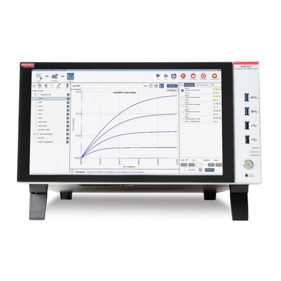
Section 6: Keithley Interactive Test Environment (KITE) Model 4200-SCS Reference Manual Overview of KITE This subsection overviews the primary features of KITE. These features allow you to create, execute, and evaluate tests and complex test sequences, interactively and without programming. - Page 137 Model 4200-SCS Reference Manual Section 6: Keithley Interactive Test Environment (KITE) Figure 6-1 KITE interface overview Toolbar Area: KITE Workspace: Site Navigator: Project Navigator: Displays the variety of Displays a variety of icons Displays the current site— Where a Project Plan is assembled,...
-
Page 138: Project Navigator
Section 6: Keithley Interactive Test Environment (KITE) Model 4200-SCS Reference Manual Project Navigator The Project Navigator is the primary interface for building, editing, and viewing a Project Plan, and for specifying and accessing each Project Plan component, as follows: •... - Page 139 Configuration is done using a simple graphical user interface. The user module that is connected to the UTM may be available in a Keithley- supplied library or may be created by the user with KULT.
-
Page 140: Interactive Test Modules (Itms) And User Test Modules (Utms)
Section 6: Keithley Interactive Test Environment (KITE) Model 4200-SCS Reference Manual Interactive Test Modules (ITMs) and User Test Modules (UTMs) KITE tests and operations are performed through interactive test modules (ITMs) and user test modules (UTMs), as called out in Figure 6-2. - Page 141 1. The 4205-PG2 and 4220-PGU pulse cards and the scope cards (4200-SCP2 or 4200-SCP2HR) are not supported by ITMs at this time. Keithley Instruments does offer the 4225-PMU pulse source and measure card which is supported by ITMs.
-
Page 142: Enabling Real Time Plotting For Utms
When using the new functions to transfer data into the data sheet in real time, make sure the data is already located in the memory of the 4200-SCS. Sweep measurements are not suitable for real time transfer because data is not ready until sweep finishes. The following examples show how to enable real time plotting for a UTM. - Page 143 Model 4200-SCS Reference Manual Section 6: Keithley Interactive Test Environment (KITE) With real time plotting: #include “keithley.h” int IV(double startv, double stopv, int numpoint, double * V, int Vsize, double * I, int Isize) int index; double stepv; // error checking if ((numpoint != Vsize) ||(numpoint != Isize)) return –1;...
-
Page 144: Defining An Itm
Section 6: Keithley Interactive Test Environment (KITE) Model 4200-SCS Reference Manual Defining an ITM An ITM is defined by the ITM Definition tab (displayed by double-clicking on the ITM name in the Project Navigator). Figure 6-4 illustrates and explains the ITM Definition tab... -
Page 145: Defining A Utm
Model 4200-SCS Reference Manual Section 6: Keithley Interactive Test Environment (KITE) Defining a UTM A UTM is defined using the UTM definition tab (displayed by double-clicking the UTM name in the project navigator). Figure 6-5 Figure 6-6 illustrate and explain the two versions of the UTM definition tab. -
Page 146: Using The Utm Gui View
Section 6: Keithley Interactive Test Environment (KITE) Model 4200-SCS Reference Manual A UTM is created and configured by first selecting a user library and user module, and then entering parameter values. For details about defining and configuring a UTM, refer to the “Configuring the UTMs”... - Page 147 Model 4200-SCS Reference Manual Section 6: Keithley Interactive Test Environment (KITE) Figure 6-6 UTM GUI definition tab Status tab: Sheet tab: Test device or other Test definition and graphical illustration Numerical test and analysis results configuration status. and test settings.
-
Page 148: Viewing Itm Or Utm Results Numerically: The Sheet Tab Data Worksheet
Section 6: Keithley Interactive Test Environment (KITE) Model 4200-SCS Reference Manual Viewing ITM or UTM results numerically: The Sheet tab Data worksheet Two other tabs that are accessible from an ITM or UTM window display data and data-analysis results. One of these, the Sheet tab displays the data numerically on the Microsoft Excel- compatible Data worksheet. -
Page 149: Viewing Itm Or Utm Results Graphically: The Graph Tab
Model 4200-SCS Reference Manual Section 6: Keithley Interactive Test Environment (KITE) Viewing ITM or UTM results graphically: The Graph tab The Graph tab displays user-specified data graphically in a user-specified format. A pop-up menu (displayed when the Graph tab is displayed, by right-clicking on the Graph tab or selecting Tools >... -
Page 150: Developing And Using User Libraries For Utms
A user module is a C-language function (subroutine). A user library is a dynamic link library (DLL) of user modules that are compiled and linked using the Keithley User Library Tool (KULT). Several user libraries are provided with the Model 4200-SCS. You can use these as-is, customize them (possible in most cases), or create completely new ones. - Page 151 Model 4200-SCS Reference Manual Section 6: Keithley Interactive Test Environment (KITE) Figure 6-9 KULT interface overview File menu: Options menu: Return Type combo box: Library: Used to: open Used to: compile the Module box: Edit menu: Used to select the output data...
-
Page 152: Creating And Using User Libraries
Section 6: Keithley Interactive Test Environment (KITE) Model 4200-SCS Reference Manual Creating and using user libraries Figure 6-10 summarizes and ties together the creation of user libraries, user modules, and UTMs. Figure 6-10 Creating and using user libraries Add/update user... -
Page 153: Basic Test Execution
Model 4200-SCS Reference Manual Section 6: Keithley Interactive Test Environment (KITE) Basic test execution NOTE If KITE detects an above-normal temperature condition at any SMU, it protects system outputs by preventing or aborting a run and reporting the condition in the message area of KITE window. -
Page 154: Executing An Individual Test
Section 6: Keithley Interactive Test Environment (KITE) Model 4200-SCS Reference Manual NOTE Figure 6-17 shows an example of Project Plan structure that shows a mix of enabled and disabled tests. Executing an individual test An enabled test must be selected before it can be run. -
Page 155: Executing An Individual Test Sequence
Model 4200-SCS Reference Manual Section 6: Keithley Interactive Test Environment (KITE) Figure 6-11 Example Project Plan Executing an individual test sequence A test sequence can include all of the tests in a Device Plan or a Subsite Plan. For example, if you... -
Page 156: Assigning A Site-Number Label To Individual Test And Test-Sequence Data
Section 6: Keithley Interactive Test Environment (KITE) Model 4200-SCS Reference Manual The Append mode may be applied to an entire test sequence (a Device Plan or Subsite Plan) as well as to a solitary test. Each time the sequence is run, the results of each test in the sequence appends to the appropriate graph. -
Page 157: Test Data
Model 4200-SCS Reference Manual Section 6: Keithley Interactive Test Environment (KITE) Test data Data for an ITM or UTM is placed into a Microsoft Excel-compatible data sheet and, after axes are defined, may be graphed. The Sheet tab Data worksheet and the Graph tab graphing tools are accessed in the KITE workspace by: Double-clicking the test name in the Project Navigator to open the ITM or UTM window. - Page 158 Section 6: Keithley Interactive Test Environment (KITE) Model 4200-SCS Reference Manual Figure 6-13 Graph settings menu Formulator: Test data can be manipulated by way of user-defined formulas. When a formula is defined, the results are automatically added to the Data worksheet of the Sheet tab and may be selectively added to the Graph tab.
-
Page 159: Multi-Site Project Plan Execution
Model 4200-SCS Reference Manual Section 6: Keithley Interactive Test Environment (KITE) Data file location By default, test data files are stored on the 4200-SCS hard disk in the following directory: • C:\S4200\kiuser\Projects\<ProjectName>\tests\data For example, the following path accesses the vds-id test data file for the example project: •... -
Page 160: Multi-Site Execution
Section 6: Keithley Interactive Test Environment (KITE) Model 4200-SCS Reference Manual In the Project window, do not change the settings on the Project CAUTION Initialization Steps or Project Termination Steps checkboxes. They are to be used only when building or modifying a Project Plan. Typically, UTMs... -
Page 161: Multi-Site Test Data
Model 4200-SCS Reference Manual Section 6: Keithley Interactive Test Environment (KITE) Figure 6-15 Multi-site test sequence Start:—— Done:—— Multi-site test data A set of data is generated for each of the selected sites. For example, five sets of data (one for... - Page 162 Section 6: Keithley Interactive Test Environment (KITE) Model 4200-SCS Reference Manual Figure 6-16 Workspace-window tab name and data file name format vds-id#1@5.xls All data that is generated by a test is stored in a file having the same naming convention as for an ITM/UTM Workspace window tab, except for the addition of an .xls (Microsoft Excel) file...
-
Page 163: Understanding Kite
The Keithley Interactive Test Environment (KITE) is the main software component of the KTE Interactive software tool set. KITE is the primary user interface for the Keithley Model 4200-SCS Semiconductor Characterization System. KITE is a versatile tool that facilitates interactive characterization of an individual parametric test device or automated testing of an entire semiconductor wafer. -
Page 164: Sites
As described in context under Sites, each test structure contains a series of devices to be characterized: transistors, diodes, resistors, capacitors, and so on. A switch matrix is used to connect the Model 4200-SCS sequentially if the SMUs cannot be connected to all devices simultaneously. -
Page 165: Project Structure
Initialization of the project. • Prober movement between project sites and subsites. • If necessary, cycling electrical connections from the Model 4200-SCS between the devices of a subsite, using switch matrices. • Execution of the tests for each device at each subsite. - Page 166 Section 6: Keithley Interactive Test Environment (KITE) Model 4200-SCS Reference Manual The active Project Plan is displayed in the KITE Project Navigator, which is the window displayed at the left of the KITE main screen. See Figure 6-18. The Project Navigator provides the following: •...
-
Page 167: Initialization And Termination Steps
Model 4200-SCS Reference Manual Section 6: Keithley Interactive Test Environment (KITE) Initialization and termination steps If the Project Plan is to be initialized and terminated automatically, initialization and termination steps are added. For example, initialization steps might be used to move a prober to a starting site and subsite or to initialize switch matrix connections to a starting configuration. - Page 168 Section 6: Keithley Interactive Test Environment (KITE) Model 4200-SCS Reference Manual Each time the prober visits a new site, the Test/Plan Indicator box updates and displays the number of the new site. Figure 6-21 illustrates the following for a Project Plan that visits five sites: •...
-
Page 169: Subsite Plan
Model 4200-SCS Reference Manual Section 6: Keithley Interactive Test Environment (KITE) Subsite Plan A Subsite Plan is a collection of Device Plans and their associated tests. Figure 6-22 highlights how a Subsite Plan is displayed in the Project Navigator. Note that the name of the selected Subsite Plan is also displayed at the top of the Project Navigator in the Test/Plan Indicator box. -
Page 170: Device Plan
Section 6: Keithley Interactive Test Environment (KITE) Model 4200-SCS Reference Manual Subsite cycling For details on subsite cycling, see Subsite cycling later in this section. NOTE Subsite cycling allows you to repeatedly cycle through the subsite tests. There are three modes of subsite cycling: Cycle Mode and Stress/Measure Mode. -
Page 171: Interactive Test Module (Itm)
Model 4200-SCS Reference Manual Section 6: Keithley Interactive Test Environment (KITE) A Device Plan is associated with a Device Plan window, which facilitates adding, removing, and rearranging of ITMs and UTMs (described in the next two subsections). A Device Plan window also allows you to submit ITMs and UTMs to a library. -
Page 172: User Test Module (Utm)
ITM functions. Additionally, UTMs may be used to manipulate instrumentation that is external to the Model 4200-SCS. For example, a prober, a C-V meter, a pulse generator, or a switch matrix can be manipulated using a UTM. A UTM can be inserted into a Project Plan in much the same way as an ITM. - Page 173 Model 4200-SCS Reference Manual Section 6: Keithley Interactive Test Environment (KITE) Parametric Test Library (LPTLib). However, any C routine that can be compiled using KULT may be used as source code for a user module. Figure 6-28 shows the Project Plan positions of two types of UTMs. The first, res_drain-to-source, is a parametric test that measures FET drain-to-source resistance at saturation.
-
Page 174: Building, Modifying, And Deleting A Project Plan
Most of these building blocks are available in Keithley-supplied libraries. However, if custom ITMs are needed, they can be created as new ITMs or by modifying existing ITMs. Custom user libraries can be created using KULT. -
Page 175: Defining The New Project Plan
Model 4200-SCS Reference Manual Section 6: Keithley Interactive Test Environment (KITE) Figure 6-30 Hierarchical Project Plan construction 1st step: Open new Project (File → New Project) 2nd step: Specify if project initialization steps are included 5th step: Insert UTMs 3rd step: Insert subsites... - Page 176 Section 6: Keithley Interactive Test Environment (KITE) Model 4200-SCS Reference Manual Configure the Define New Project window to meet the needs of your Project Plan, as follows: • Project Name edit box: Enter the Project Plan name, subject to the following rules.
- Page 177 Model 4200-SCS Reference Manual Section 6: Keithley Interactive Test Environment (KITE) Click OK. The Project Navigator appears, reflecting the chosen configuration. See Figure 6-33. Figure 6-33 Initial Project Navigator window for the u-build Project Plan NOTE After you configure the Define New Project window, the Project Plan, essentially empty, exists in the selected file location.
- Page 178 Section 6: Keithley Interactive Test Environment (KITE) Model 4200-SCS Reference Manual Add a Subsite Plan to the Project Plan as follows: a. Do either of the following: • In the Project menu, click New Subsite Plan. • On the Project Plan toolbar, click the Add Subsite Plan button. See Figure 6-35.
- Page 179 C:\4200\kiuser\Devices or an equivalent personal device library such as C:\4200\YourName\Devices. The devices available in the library include the standard set of devices that come installed on the Model 4200-SCS, as well as any custom-name devices that you have submitted (the submittal procedure is discussed under...
- Page 180 Section 6: Keithley Interactive Test Environment (KITE) Model 4200-SCS Reference Manual Insert a Device Plan using the default name, as follows: In the Project Navigator, select the Subsite Plan component below to insert the first device. To add the first Device Plan to subsite_a of the u_build Project Plan, the appropriate component to select is subsite_a.
- Page 181 Model 4200-SCS Reference Manual Section 6: Keithley Interactive Test Environment (KITE) b. In the Add New Device Plan to Project window, select a new Device Plan from the default device library. For the u_build Project Plan, the first Device Plan to be added is a MOSFET Device Plan called 4terminal-n-fet.
- Page 182 Section 6: Keithley Interactive Test Environment (KITE) Model 4200-SCS Reference Manual When the Add New Device Plan to Project window opens, do the following: a. Select the device to be added. For the u_build Project Plan, 4terminal-n-fet was selected again for insertion in subsite_a, to illustrate that multiple instances of a given device are permitted anywhere in the Project Plan if each instance is given a different name.
- Page 183 Model 4200-SCS Reference Manual Section 6: Keithley Interactive Test Environment (KITE) Inserting multiple instances of a Device Plan using the same name You may not insert multiple instances of a Device Plan with the same name in the same Subsite Plan.
- Page 184 Section 6: Keithley Interactive Test Environment (KITE) Model 4200-SCS Reference Manual Inserting the ITMs The next step, after inserting Device Plans into your Project Plan, is to insert the ITMs and UTMs. This manual discusses and illustrates ITM insertion before UTM insertion. However, depending on your needs and preferences, the reverse order of insertion (or a mixed order of insertion) may be advantageous.
- Page 185 C:\4200\YourName\Tests. Such a library typically includes the standard set of ITMs that come installed on the Model 4200-SCS, as well as any custom ITMs that you have submitted (the submittal procedure is discussed under...
- Page 186 Section 6: Keithley Interactive Test Environment (KITE) Model 4200-SCS Reference Manual Figure 6-50 Device Plan Window In the Test Libraries combo box, select the test library that contains the desired ITM. The default test library is , unless another library, such as a...
- Page 187 Model 4200-SCS Reference Manual Section 6: Keithley Interactive Test Environment (KITE) Figure 6-51 Example of ITMs listed under a device type Select the desired test. Figure 6-52 illustrates selection of the “vds_id” ITM for the u_build Project Plan. Figure 6-52 Selecting an ITM Many ITMs contain sample data.
- Page 188 Section 6: Keithley Interactive Test Environment (KITE) Model 4200-SCS Reference Manual Figure 6-54 Adding an ITM to the Test Sequence Table If, under Test Sequence Table, an ITM is not at the preferred position in the sequence, do this: a. Select the ITM to be moved.
- Page 189 Model 4200-SCS Reference Manual Section 6: Keithley Interactive Test Environment (KITE) In the Device Plan window, below the list of ITMs, click the Copy As button. The Copy Test dialog box appears. See Figure 6-57. Figure 6-57 Copy Test dialog box In the Copy Test dialog box, enter the new name for the ITM.
- Page 190 Section 6: Keithley Interactive Test Environment (KITE) Model 4200-SCS Reference Manual Figure 6-60 Renamed KITE library ITM inserted in the Project Plan Inserting multiple instances of a library ITM using the same name You may insert multiple instances of any ITM (from any ITM library) anywhere in the Project Plan using the same name.
- Page 191 Model 4200-SCS Reference Manual Section 6: Keithley Interactive Test Environment (KITE) Figure 6-62 Result of pressing Copy to add a same-named ITM within a given Subsite Plan Select “vds-id” ITM and press Copy Figure 6-63 Result of pressing Copy to add a same-named ITM to a different Subsite Plan Select “vds-id”...
- Page 192 Section 6: Keithley Interactive Test Environment (KITE) Model 4200-SCS Reference Manual Option II. Insert the ITM as-is: If you specifically need a same-named ITM and the rules for same-named ITM meet your test objectives, insert it without renaming it, as follows: Click Overwrite in the Test Already Exists message box.
- Page 193 Model 4200-SCS Reference Manual Section 6: Keithley Interactive Test Environment (KITE) Click Apply. The following occurs: • The new ITM is added to the Project Plan. • All previously inserted same-named ITMs match the newly inserted ITM (except for their data, Sheet tabs, Graph tabs, and UID numbers).
- Page 194 Inserting the UTMs In contrast to ITMs, relatively few UTMs are presently provided by Keithley Instruments in the C:\S4200\kiuser\Tests library. If these are insufficient, you must initially create additional UTMs (which you can subsequently submit to C:\S4200\kiuser\Tests or to a personal library).
- Page 195 Model 4200-SCS Reference Manual Section 6: Keithley Interactive Test Environment (KITE) NOTE Connecting a UTM name with a user library and user module and entering the required parameters is discussed subsequently under Configuring the UTMs later in this section. If, after creating a UTM, you submit it to C:\S4200\kiuser\Tests or to a personal library, you can subsequently insert it from this library in the same way as an ITM.
- Page 196 Section 6: Keithley Interactive Test Environment (KITE) Model 4200-SCS Reference Manual • Above and below ITMs and other UTMs. The instructions in this subsection reflect adding the UTM below an ITM or UTM. For illustration purposes, the UTM name will be added to the u_build Project Plan below a Device Plan.
-
Page 197: Modifying An Existing Project Plan
Model 4200-SCS Reference Manual Section 6: Keithley Interactive Test Environment (KITE) Click OK. The new UTM is inserted into the Project Plan. See Figure 6-76. Figure 6-76 New UTM entered into the Project Plan Inserting a library UTM If a UTM of a desired type exists in a test library, you insert it from the library in exactly the same way as you would insert an ITM from the library, except as follows: •... -
Page 198: Opening An Existing Project Plan
Section 6: Keithley Interactive Test Environment (KITE) Model 4200-SCS Reference Manual Opening an existing Project Plan To open an existing Project Plan, do the following: In the File menu, select Open Project. The Open KITE Project File window appears, displaying a file tree for the Project Plan that was last opened in KITE. See Figure 6-77. - Page 199 Model 4200-SCS Reference Manual Section 6: Keithley Interactive Test Environment (KITE) b. Double-click on the <ProjectName> folder (the folder that contains the Project Plan to be opened). The Open KITE Project File window displays the file tree for the Project Plan to be opened.
-
Page 200: Saving A Project Plan Under A New Name
Section 6: Keithley Interactive Test Environment (KITE) Model 4200-SCS Reference Manual Saving a Project Plan under a new name To create a completely new Project Plan from an existing source Project Plan, start by saving the source Project Plan under a new name. Do the following: Take one or both of the actions below, as required: a. -
Page 201: Adding And Deleting Initialization And Termination Steps
Model 4200-SCS Reference Manual Section 6: Keithley Interactive Test Environment (KITE) Figure 6-83 New u_mod Project Plan created from the u_build Project Plan using Save Project As Adding and deleting initialization and termination steps Adding initialization or termination steps Add initialization or termination steps as follows: Double-click the Project Plan name at the top of the Project Navigator tree. -
Page 202: Adding, Rearranging, And Deleting Subsite Plans
Section 6: Keithley Interactive Test Environment (KITE) Model 4200-SCS Reference Manual Figure 6-85 Termination steps added Deleting initialization or termination steps Deleting initialization or termination steps deletes ALL UTMs in the CAUTION initialization or termination steps. Delete initialization or termination steps as follows: In the Project Navigator, select the intitialization or termination steps. - Page 203 Model 4200-SCS Reference Manual Section 6: Keithley Interactive Test Environment (KITE) Figure 6-87 Project window Select the Sequence tab of the Project window. The Sequence tab opens, displaying the Subsite Sequence Table. Figure 6-88 shows the Subsite Sequence Table for the u_mod Project Plan.
- Page 204 Section 6: Keithley Interactive Test Environment (KITE) Model 4200-SCS Reference Manual NOTE To select a sequential group of Subsite Plans, hold down the SHIFT key and click on the first and last subsite to be included. Figure 6-89 shows subsite_b selected in the Subsite Sequence Table of the u_mod Project Plan.
-
Page 205: Adding, Rearranging, And Deleting Device Plans
Model 4200-SCS Reference Manual Section 6: Keithley Interactive Test Environment (KITE) Deleting a Subsite Plan Deleting a Subsite Plan deletes all Device Plans and tests in the Subsite CAUTION Plan. Delete a Subsite Plan as follows: In the Project Navigator, select the Subsite Plan. - Page 206 Section 6: Keithley Interactive Test Environment (KITE) Model 4200-SCS Reference Manual Figure 6-94 Subsite Plan window opened for 4terminal-n-fet-2nd_in_subsite Device Plan to be relocated In the Device Sequence Table of the Subsite Plan window, select the Device Plans to be moved.
- Page 207 Model 4200-SCS Reference Manual Section 6: Keithley Interactive Test Environment (KITE) Figure 6-96 Relocated 4terminal-n-fet-2nd_in _subsite Device Plan in Device Sequence Table Click Apply in the lower right corner of the Subsite Plan window. The Device Plan is relocated in the Project Plan. See Figure 6-97.
-
Page 208: Rearranging And Deleting Itms And Utms
Section 6: Keithley Interactive Test Environment (KITE) Model 4200-SCS Reference Manual Rearranging and deleting ITMs and UTMs Rearranging ITMs and UTMs You can rearrange the order of ITMs and UTMs within a Device Plan, as follows: In the Project Navigator, locate the Device Plan that contains the ITMs or UTMs to be relocated (hereafter, referred to as “tests”... - Page 209 Model 4200-SCS Reference Manual Section 6: Keithley Interactive Test Environment (KITE) In the Test Sequence Table of the Device Plan window, select the tests to be moved. To select a sequential group of tests, which can be a mixture of ITMs and UTMs, hold NOTE down the SHIFT key and click on the first and last test to be included.
-
Page 210: Deleting A Project Plan
Section 6: Keithley Interactive Test Environment (KITE) Model 4200-SCS Reference Manual Deleting an ITM or UTM Delete an ITM or UTM as follows: In the Project Navigator, select the ITM or UTM. Press the DELETE key on the keyboard (alternatively, right-click on the ITM or UTM and, in the pop-up menu that appears, select Delete). - Page 211 Model 4200-SCS Reference Manual Section 6: Keithley Interactive Test Environment (KITE) Figure 6-106 Next-file-level-up button • If the Project Plan to be deleted is not in the default user directory, in the Look In combo box browse for and insert the correct Project Plan directory (typically <Path>\Projects).
-
Page 212: Configuring The Project Plan Itms
Section 6: Keithley Interactive Test Environment (KITE) Model 4200-SCS Reference Manual Figure 6-109 Open KITE Project File window, reflecting deletion of the delete_this Project Plan In the Open KITE Project File window, click Cancel. The Open KITE Project File window closes. -
Page 213: Opening An Itm Window
Model 4200-SCS Reference Manual Section 6: Keithley Interactive Test Environment (KITE) Configuration of ITMs is discussed under the following topics: • Opening an ITM window • Becoming acquainted with the ITM Definition tab • Matching Definition tab terminal connections to physical connections •... -
Page 214: Becoming Acquainted With The Itm Definition Tab
Section 6: Keithley Interactive Test Environment (KITE) Model 4200-SCS Reference Manual NOTE An ITM window for a chosen ITM may already be open but hidden behind another ITM or UTM window. If so, double-click on the ITM in the Project Navigator. The ITM window will be brought into the foreground (If Workbook Mode has been selected in >... - Page 215 Model 4200-SCS Reference Manual Section 6: Keithley Interactive Test Environment (KITE) Figure 6-111 ITM Definition tab example Instrument- selection FORCE/MEASURE combo boxes buttons Instrument- objects An ITM Definition tab does the following: • Displays the test device schematically. • Displays an instrument object next to each terminal of the device under test. The instrument...
-
Page 216: Itm Status Tab
Section 6: Keithley Interactive Test Environment (KITE) Model 4200-SCS Reference Manual The ITM window displaying the Definition tab shown in Figure 6-111 was opened by double- clicking a “vds-id” ITM in the Project Navigator for the u_build Project Plan (for more information... -
Page 217: Matching Definition Tab Terminal Connections To Physical Connections
Model 4200-SCS Reference Manual Section 6: Keithley Interactive Test Environment (KITE) Figure 6-113 Status tab report for the unconfigured charge_char ITM By contrast, the Status tab indicates that the first “vds-id” ITM of the u_build Project Plan is ready to execute. See Figure 6-114. -
Page 218: Selecting The Itm Test Mode
Section 6: Keithley Interactive Test Environment (KITE) Model 4200-SCS Reference Manual Figure 6-115 illustrates assignment of a terminal connection. Figure 6-115 Assigning a terminal connection in the Definition tab Figure 6-116 shows instrument objects of the previously blank Definition tab for the charg_char ITM. -
Page 219: Assigning/Reassigning Forcing Functions To The Device Terminals
Model 4200-SCS Reference Manual Section 6: Keithley Interactive Test Environment (KITE) • For an existing library ITM that is in the Sweeping mode, the Mode combo box allows you only to observe that it is in the Sweeping mode. You cannot change the Sweeping mode to Sampling mode, unless you first change all of the dynamic forcing functions of the ITM to static forcing functions. - Page 220 Section 6: Keithley Interactive Test Environment (KITE) Model 4200-SCS Reference Manual Table 6-6 Forcing function summary Availability Category Name Description • • Static Open Maintains a zero-current state at the terminal, subject to the maximum voltage compliance of the connected SMU.
-
Page 221: Assigning Forcing Functions For A Completely New Itm
Model 4200-SCS Reference Manual Section 6: Keithley Interactive Test Environment (KITE) Assigning forcing functions for a completely new ITM As illustrated in Figure 6-116, all SMU-connected terminals for a completely new ITM are assigned by default to a Common forcing function. For the ITM to be useful, at least one of the device terminals must be reassigned to a forcing function that applies a voltage or current. - Page 222 Section 6: Keithley Interactive Test Environment (KITE) Model 4200-SCS Reference Manual Replacing the default forcing function with a new forcing function To assign a replacement forcing function to a device terminal, do the following: On the Forcing Function/Measure Options window, click the arrow key next to the Forcing Functions combo box.
-
Page 223: Reassigning Forcing Functions For An Existing Library Itm
Model 4200-SCS Reference Manual Section 6: Keithley Interactive Test Environment (KITE) Figure 6-120 Example of a reassigned forcing function Click OK. The new Forcing Function/Measure Options window closes. Save the change. Figure 6-121 shows the result of the reassignment that was made per... -
Page 224: Configuring Smu Forcing Functions/Measure Options Window
Section 6: Keithley Interactive Test Environment (KITE) Model 4200-SCS Reference Manual Configuring SMU Forcing Functions/Measure Options window A Forcing Functions/Measure Options window is associated with an instrument object that is assigned to a device terminal. The Forcing Functions/Measure Options window is used to configure the selected forcing function and measurements implemented by the instrument. -
Page 225: Reviewing A Typical Forcing Functions/Measure Options Window
Model 4200-SCS Reference Manual Section 6: Keithley Interactive Test Environment (KITE) Reviewing a typical Forcing Functions/Measure Options window A typical Forcing Functions/Measure Options window, as shown in Figure 6-122, is divided as follows: • The Instrument Information area. • The Forcing Function area. - Page 226 Section 6: Keithley Interactive Test Environment (KITE) Model 4200-SCS Reference Manual • Sweep forcing-functions (displayed only in the Sweeping test mode) - The Current Sweep forcing function - The Voltage Sweep forcing function • List-sweep forcing functions (displayed only in the Sweeping test mode)
- Page 227 Model 4200-SCS Reference Manual Section 6: Keithley Interactive Test Environment (KITE) Minimize this extra time by choosing custom in the timing tab and setting delay and filter factor to 0, and A/D Integration factor to 0.01. This is the fastest (but least accurate) measurement timing scheme.
-
Page 228: The Forcingfunctionname Function Parameters Area
Section 6: Keithley Interactive Test Environment (KITE) Model 4200-SCS Reference Manual The ForcingFunctionName function parameters area This subsection provides the following: • Explains each of the ten forcing functions, with amplification and examples as needed. • Shows an example of each of the ten Forcing Functions/Measure Options windows. - Page 229 Model 4200-SCS Reference Manual Section 6: Keithley Interactive Test Environment (KITE) No function parameters are user configurable for the Open forcing function. Understanding and configuring the Common forcing function The Common forcing function maintains a zero-voltage state at the terminal, subject to the maximum current compliance of the connected SMU.
- Page 230 Section 6: Keithley Interactive Test Environment (KITE) Model 4200-SCS Reference Manual Figure 6-127 Current Bias Forcing Functions/Measure Options window The Current Bias (VMU) Function Parameters are configurable as follows: • The Level parameter edit box specifies the SMU current to be forced, the units for that are selected through the combo box at the right of the edit box.
- Page 231 Model 4200-SCS Reference Manual Section 6: Keithley Interactive Test Environment (KITE) Figure 6-128 Voltage Bias Forcing Functions/Measure Options window The Voltage Bias Function Parameters are configurable as follows: • The Level parameter edit box specifies any valid SMU voltage, the units for which are selected through the combo box at the right of the edit box.
- Page 232 Section 6: Keithley Interactive Test Environment (KITE) Model 4200-SCS Reference Manual Understanding and configuring the Current Sweep forcing function More specifically, the Current Sweep forcing function increments through a series of current steps over a user-specified range, subject to a user-specified voltage compliance. In a Linear sweep, the user-specified step size is uniform.
- Page 233 Model 4200-SCS Reference Manual Section 6: Keithley Interactive Test Environment (KITE) - For example: If Start = 0A, Stop = 0.005 A, and Step = 0.0006 A: • Data Points value = integer of [1 + (0.005 - 0)/(0.0006)] = integer of [9.333] = 9 •...
- Page 234 Section 6: Keithley Interactive Test Environment (KITE) Model 4200-SCS Reference Manual Understanding and configuring the Voltage Sweep forcing function The Voltage Sweep forcing function increments through a series constant voltage steps over a user-specified range, subject to a user-specified current compliance. In a Linear sweep, the user- specified step size is uniform.
- Page 235 Model 4200-SCS Reference Manual Section 6: Keithley Interactive Test Environment (KITE) For linear sweeps, the Step parameter may be any valid SMU voltage value, the units for which are selected through the combo box at the right of the edit box. However, note the following: - It is best to specify a Step value that divides evenly into (Stop value - Start value).
- Page 236 Section 6: Keithley Interactive Test Environment (KITE) Model 4200-SCS Reference Manual NOTE Pulse Mode can be selected ONLY when source and measure ranges are fixed. In other words, Pulse Mode is disabled if the source or measure range is set to AUTO.
- Page 237 Model 4200-SCS Reference Manual Section 6: Keithley Interactive Test Environment (KITE) The Stop, Start, and Data Points values in the above equations are as specified in the Function Parameters area of a Current Sweep or Voltage Sweep Forcing Functions/Measure Options window.
- Page 238 Section 6: Keithley Interactive Test Environment (KITE) Model 4200-SCS Reference Manual Understanding Master Sweeps vs. Slave Sweeps It is possible to simultaneously apply multiple sweep forcing functions to multiple device terminals. However, all of the sweep forcing functions in the ITM must track with regard to increment number and duration.
- Page 239 Model 4200-SCS Reference Manual Section 6: Keithley Interactive Test Environment (KITE) Understanding a Dual Sweep A SMU that is configured to perform a linear or log sweep, can also be set to perform a dual sweep. With Dual Sweep enabled, the SMU will essentially perform two sweeps. The first sweep steps from the Start level to the Stop level.
- Page 240 Section 6: Keithley Interactive Test Environment (KITE) Model 4200-SCS Reference Manual List sweep forcing functions A list sweep forcing function steps a current or voltage through a list of user-specified values at a rate that is determined by the Timing and Speed settings in the ITM Definition tab. This sweep generates parametric data that is recorded in the ITM Sheet tab Data worksheet and can be plotted in the ITM Graph tab, if desired.
- Page 241 Model 4200-SCS Reference Manual Section 6: Keithley Interactive Test Environment (KITE) Figure 6-137 Results of increasing the Data Points value beyond the default of 10 - If you decrease the Data Points value from any prior size, say from size N to size M, the parameter list shrinks;...
- Page 242 Section 6: Keithley Interactive Test Environment (KITE) Model 4200-SCS Reference Manual • Compliance: The Compliance parameter edit box specifies any valid SMU voltage compliance limit, the units for which are selected through the combo box at the right of the edit box.
- Page 243 Model 4200-SCS Reference Manual Section 6: Keithley Interactive Test Environment (KITE) The Voltage List Sweep Function Parameters are configurable as listed below: • Parameter list: The parameter list specifies the sequence and value of each voltage to be forced during the list sweep. Each parameter value may be any valid SMU voltage.
- Page 244 Section 6: Keithley Interactive Test Environment (KITE) Model 4200-SCS Reference Manual Figure 6-141 Results of decreasing the Data Points value • Src Range: The Src Range (source range) combo box specifies the SMU voltage range that is used to force the sweep voltages, per the following options: - The Auto option commands the SMU to automatically change to the optimal range as the sweep progresses.
- Page 245 Model 4200-SCS Reference Manual Section 6: Keithley Interactive Test Environment (KITE) Figure 6-142 List Sweep Function general illustration Time Understanding Master List Sweeps vs. Slave List Sweeps It is possible to simultaneously apply multiple list sweep forcing functions to multiple device terminals.
- Page 246 Section 6: Keithley Interactive Test Environment (KITE) Model 4200-SCS Reference Manual Figure 6-143 Master Lists Sweep Function vs. Slave List Sweep Function Master List Sweep Function Time Step width and number of steps of slave function track step width and number of steps...
- Page 247 Model 4200-SCS Reference Manual Section 6: Keithley Interactive Test Environment (KITE) In Forcing Functions/Measure Options windows, KITE enforces tracking between master list-sweep and slave list sweep user entries is as follows: • When a slave list sweep function is assigned to the ITM (by default, after the master...
- Page 248 Section 6: Keithley Interactive Test Environment (KITE) Model 4200-SCS Reference Manual Figure 6-144 Current Step Forcing Functions/Measure Options window The Current Step Function Parameters are configurable as listed below. • Start: The Start edit box specifies the current forced for the first step value. The Start parameter may be any valid SMU current, the units for which are selected through the combo box at the right of the edit box.
- Page 249 Model 4200-SCS Reference Manual Section 6: Keithley Interactive Test Environment (KITE) - The Best Fixed option commands the SMU to automatically select the single current range that best fits the entire step range. - The numerical current range options allow you to manually select an SMU range to suit your needs.
- Page 250 Section 6: Keithley Interactive Test Environment (KITE) Model 4200-SCS Reference Manual - It is best to specify a Step value that divides evenly into (Stop value - Start value). If the ratio [(Stop value - Start value)/(Step value)] is not an integer, the last, fractional step increment of the sweep is rejected and the last voltage value is smaller than the Stop value.
- Page 251 Model 4200-SCS Reference Manual Section 6: Keithley Interactive Test Environment (KITE) Figure 6-147 graphically illustrates the combined Step and Sweep forcing functions specified in Figure 6-146. Figure 6-147 Stepping and sweeping example Stepping the Gate Voltage of a FET Step 4...
-
Page 252: Understanding And Configuring The Measuring Options Area
Section 6: Keithley Interactive Test Environment (KITE) Model 4200-SCS Reference Manual To specify a particular step function as the master step function, click the Master checkbox in the Forcing Function area of its Forcing Functions/Measure Options window. If you do not specify a particular step function as the master step function, the first step function that you assign to an ITM is the master function, by default. - Page 253 Model 4200-SCS Reference Manual Section 6: Keithley Interactive Test Environment (KITE) Current Range combo box The current Range (measure range) combo box is present for voltage forcing functions only. Here you specify the measurement range to be used by the SMU for current, from the following options: •...
- Page 254 Section 6: Keithley Interactive Test Environment (KITE) Model 4200-SCS Reference Manual Voltage Range combo box The voltage Range (measure range) combo box is present for current forcing functions only. Here you specify the measurement range to be used by the SMU for voltage, from the following options: •...
- Page 255 Model 4200-SCS Reference Manual Section 6: Keithley Interactive Test Environment (KITE) Table 6-7 explains the groups of code bits. Table 6-7 ITM status-code bit map Summary Description Details Reserved Reserved bits are reserved for future use. The state of reserved status bits is undefined and is not guaranteed under any conditions, unless specifically indicated.
-
Page 256: Configuring The Speed And Timing Settings In The Itm Definition Tab
Section 6: Keithley Interactive Test Environment (KITE) Model 4200-SCS Reference Manual Configuring the Speed and Timing settings in the ITM Definition tab Two key issues in making good measurements with a low-current semiconductor analyzer are addressed by way of controls on the ITM Definition tab (settling time and noise). -
Page 257: Speed Combo Box
Speed combo box, as well as in the ITM Timing window (discussed in the next subsection): • Fast: Optimizes the 4200-SCS for speed at the expense of noise performance. It is a good choice for fast and dirty measurements where noise and settling time are not concerns. •... -
Page 258: Timing Window
Model 4200-SCS Reference Manual Timing window The Timing window is used to configure ITM timing settings for a 4200-SCS SMU. Three of the settings can be configured only in the Custom measurement Speed mode. The others can be configured in all measurement Speed modes. You can do the following in the Timing window: •... - Page 259 A delay factor of 0 multiplies the default delay by zero, resulting in no delay. Filter Factor setting To reduce measurement noise, each 4200-SCS SMU applies filtering, which may include averaging of multiple readings to make one measurement. The SMU automatically adjusts the...
- Page 260 The entry in the A/D Integration Time edit box controls the A/D converter integration time used to measure a signal. Each measured reading by a 4200-SCS SMU is the result of one or more A/D (analog-to-digital) conversions. A short integration time for each A/D conversion results in a relatively fast measurement-speed at the expense of noise.
- Page 261 Model 4200-SCS Reference Manual Section 6: Keithley Interactive Test Environment (KITE) Table 6-10 Summary of allowed A/D Integration Time settings Speed A/D Integration Time Mode Setting Fast Auto Normal Auto Quiet Auto Custom 0.01 to 10 PLC Understanding and configuring the Sweeping Mode area of the Timing window If any terminal of the device under test is configured for a dynamic forcing function (a step or sweep forcing function) the Sweeping Mode is automatically enabled.
- Page 262 Section 6: Keithley Interactive Test Environment (KITE) Model 4200-SCS Reference Manual Figure 6-153 Sweeping Mode timing diagram The timing elements in Figure 6-153 act as follows: • Hold Time (HT): The sweep graph shows two sweeps that correspond to the two steps shown directly above in the step graph.
- Page 263 Model 4200-SCS Reference Manual Section 6: Keithley Interactive Test Environment (KITE) Understanding and configuring the Sampling Mode area of the Timing window The sampling mode allows measuring of voltages/currents as a function of time while forcing constant voltages/currents. For example, sampling mode would be used to profile capacitor charging voltage while forcing a constant current.
- Page 264 Section 6: Keithley Interactive Test Environment (KITE) Model 4200-SCS Reference Manual The timing elements in Figure 6-154 act as follows: • If needed, you can use a Hold Time (HT) to allow for extra source settling after initial application of voltages/currents by the SMUs. Hold Time is a global setting and is therefore the same for all SMUs in the test system.
- Page 265 Model 4200-SCS Reference Manual Section 6: Keithley Interactive Test Environment (KITE) If KITE takes and averages multiple readings for a measurement, then KITE records the timestamp at the last of these readings. See Figure 6-156. Figure 6-156 Application of timestamps when KITE requires multiple readings for a measurement...
-
Page 266: Configuring Formulator Calculations
Factor can be increased to allow for the added settling time. A little trial-and-error experimentation is needed. However, for a good quality switch, such as the Keithley Instruments Model 7174A Ultra Low Current matrix, you should not need to increase the Delay Factor by more than 2X. -
Page 267: Itm Compliance Exit Conditions
Subsite: The 4200-SCS exits the Subsite Plan presently being run. If configured to run another Subsite Plan, operation continues on to that plan. • Site: The 4200-SCS exits the Site. If configured to test another Site, operation continues on to that site. •... -
Page 268: Itm Output Values
Section 6: Keithley Interactive Test Environment (KITE) Model 4200-SCS Reference Manual ITM Output Values The measured readings for an ITM test can export (output) to a Subsite Data sheet for subsite cycling. The exported readings for an ITM test are called Output Values. - Page 269 Model 4200-SCS Reference Manual Section 6: Keithley Interactive Test Environment (KITE) • Inputting the UTM parameters • Configuring Formulator calculations • Saving the UTM configuration • UTM Output Values Figure 6-160 Relationships between a Project Plan, a UTM, a user module, and user libraries...
-
Page 270: Opening A Utm Window
Section 6: Keithley Interactive Test Environment (KITE) Model 4200-SCS Reference Manual Opening a UTM window A UTM window allows you to enter information that defines a given UTM. A UTM window also allows you to view and analyze test data created by the UTM, both numerically and graphically. - Page 271 Model 4200-SCS Reference Manual Section 6: Keithley Interactive Test Environment (KITE) which was obtained by double-clicking the unconfigured res_drain-to-source UTM in the u_build Project Plan (Figure 6-162). Figure 6-163 Blank UTM Definition tab User-module combo box User-library Present-cell combo box...
-
Page 272: Connecting/Reconnecting The Utm To A User Library And Module
Section 6: Keithley Interactive Test Environment (KITE) Model 4200-SCS Reference Manual Connecting/reconnecting the UTM to a user library and module For a UTM to perform a task, it must be connected to a KULT created user library and user module. This subsection describes how to make a user-library / module connection for a new UTM or revise the user library/module for a previously configured UTM. -
Page 273: Inputting The Utm Parameters
Model 4200-SCS Reference Manual Section 6: Keithley Interactive Test Environment (KITE) Inputting the UTM parameters Most user modules provide default input parameter values (see the Value column in Figure 6-164). You may use the default value of any parameter or enter a new value, as follows: In the parameter-cell matrix, double-click the cell in which you want to enter the new parameter value. -
Page 274: Saving The Utm Configuration
Section 6: Keithley Interactive Test Environment (KITE) Model 4200-SCS Reference Manual Saving the UTM configuration Save the UTM configuration, by either of the following methods: • Click the Save diskette icon at the top of the KITE window. • In the File menu, select Save. -
Page 275: Submitting Devices To A Library
Model 4200-SCS Reference Manual Section 6: Keithley Interactive Test Environment (KITE) Submitting devices to a library You may submit a Project Plan device (an empty Device Plan) to any device library, as long as you submit it under a name that does not duplicate a device name that is already in the library. - Page 276 Section 6: Keithley Interactive Test Environment (KITE) Model 4200-SCS Reference Manual If you wish to submit the Device Plan to a device library directory other than the default device library directory, select the alternate device library directory in the Device Library combo box of the Subsite Plan window.
-
Page 277: Submitting Tests To A Library
Model 4200-SCS Reference Manual Section 6: Keithley Interactive Test Environment (KITE) Do one of the following: • To submit the selected devices with the original names, click the Submit >> button in the Subsite Plan window. The selected devices are submitted to the chosen folder. - Page 278 Section 6: Keithley Interactive Test Environment (KITE) Model 4200-SCS Reference Manual Submit the UTMs or ITMs (hereafter, mostly referred to as tests) as follows: In the Project Navigator, locate the Device Plan that contains the tests that you wish to submit.
- Page 279 Model 4200-SCS Reference Manual Section 6: Keithley Interactive Test Environment (KITE) If you wish to submit the tests to a test library directory other than the default test library directory, select the alternate test library directory in the Test Library combo box of the Device Plan window.
-
Page 280: Copying Tests From A Library
Section 6: Keithley Interactive Test Environment (KITE) Model 4200-SCS Reference Manual Figure 6-175 Submit test dialog box In the As edit box of the Submit test dialog box, type the submittal name for the test. Click OK. One of the following occurs: •... - Page 281 Model 4200-SCS Reference Manual Section 6: Keithley Interactive Test Environment (KITE) When finished, click the Apply button (see Figure 6-180). Figure 6-176 Project tree with diode device selected Figure 6-177 Diode device plan 4200-901-01 Rev. S / May 2017 Return to...
- Page 282 Section 6: Keithley Interactive Test Environment (KITE) Model 4200-SCS Reference Manual Figure 6-178 Test already exists prompt Figure 6-179 Copy as prompt Figure 6-180 Device plan after submitting test 4200-901-01 Rev. S / May 2017 6-156 Return to Section Topics...
-
Page 283: Executing Project Plans, Subsite Plans, Device Plans, And Tests
Model 4200-SCS Reference Manual Section 6: Keithley Interactive Test Environment (KITE) Executing Project Plans, Subsite Plans, Device Plans, and tests You can execute an entire Project Plan or individual parts of the Project Plan. To describe how, this subsection discusses the following topics: •... - Page 284 Section 6: Keithley Interactive Test Environment (KITE) Model 4200-SCS Reference Manual NOTE You must specify, in the Project window, the site numbers with which collected data is to be labeled. You must also independently position the prober such that the sites to be evaluated on the wafer are identical to the sites that are specified in the Project window.
- Page 285 Model 4200-SCS Reference Manual Section 6: Keithley Interactive Test Environment (KITE) Figure 6-185 Example of Project window In the Project window, set the Start Execution at Site and the Finish Execution at Site numbers as described in Figure 6-186. In the Project window, the Number of Sites is set 1) typically, to specify the number NOTE of sites that have been programmed in a prober controller;...
- Page 286 Project Plan (NOTE: If you wish to evaluate only a single site, OR if the Model 4200-SCS is not connected to a semi-automatic prober or the Project Plan does not contain a probe-step UTM, enter here the same number as in the Start Execution at Site edit box).
- Page 287 Model 4200-SCS Reference Manual Section 6: Keithley Interactive Test Environment (KITE) NOTE If you select a node other than the project node, KITE runs only the test or the test sequence at the node, and runs it only one time. Also, KITE labels the resulting data with the site number that is specified in the Site Navigator, not the Start Execution at Site number specified in the Project window.
-
Page 288: Run Execution Of Individual Tests And Test Sequences
Section 6: Keithley Interactive Test Environment (KITE) Model 4200-SCS Reference Manual Figure 6-191 Multi-site execution process, as displayed in the Test/Plan Indicator box Project execution starts. The initialization-step UTMs, if any, execute. Initialization Other tests execute for the starting site. The data labels... -
Page 289: Run' Execution Of Individual Subsite Plans
Figure 6-192 Save All icon If the Model 4200-SCS is connected to a prober, do the following: a. Place the probe at the site that contains the subsite to be evaluated. b. Using the Site Navigator (located above the Project Navigator), scroll to the number of the site where you placed the probe in step 2a (use the spin buttons). - Page 290 Section 6: Keithley Interactive Test Environment (KITE) Model 4200-SCS Reference Manual Start execution. Click the green triangular Run Test/Plan toolbar button (see below), select Run in the KITE Run menu, or press the F6 keyboard key. Figure 6-195 KITE Run Test/Plan icon The green Run Test/Plan toolbar button becomes gray, the Subsite Plan executes, and the square Abort Test/Plan icon illuminates red for the duration of the test (see below).
-
Page 291: Run' Execution Of Individual Device Plans
Figure 6-200 Save All icon If the Model 4200-SCS is connected to a prober, do the following: a. Place the probe at the site that contains the device to be evaluated. b. Using the Site Navigator (located above the Project Navigator) scroll to the number of the site where you placed the probe in step 2a (Use the spin buttons). - Page 292 Save All icon at the top of the KITE screen (see below) or by clicking Save All in the KITE File menu. Figure 6-207 KITE Save All icon If the Model 4200-SCS is connected to a prober, do the following: 4200-901-01 Rev. S / May 2017 6-166 Return to...
- Page 293 Model 4200-SCS Reference Manual Section 6: Keithley Interactive Test Environment (KITE) a. Place the probe at the site that contains the ITM or UTM to be evaluated. b. Using the Site Navigator (located above the Project Navigator), scroll to the number of the site where you placed the probe in step 2a (use the spin buttons).
-
Page 294: Append Execution Of Tests, Test Sequences, And Project Plans
Section 6: Keithley Interactive Test Environment (KITE) Model 4200-SCS Reference Manual Simultaneously, the Execution Indicator toolbar button (see below) traces miniature curves and changes color for the duration of the test. Figure 6-212 KITE Execution Indicator button As the test executes, the Test/Plan Indicator box displays its data label (refer to... - Page 295 Model 4200-SCS Reference Manual Section 6: Keithley Interactive Test Environment (KITE) Figure 6-215 Append worksheet tab illustration Append worksheet tabs • In the Graph tab, the Append data curves for a test append to (layer on top of) the Run- data curves.
-
Page 296: Specifying The Maximum Number Of Append Worksheets
Section 6: Keithley Interactive Test Environment (KITE) Model 4200-SCS Reference Manual Specifying the maximum number of Append worksheets Understanding the maximum number of Append worksheets The maximum number of Append worksheets is set in the Project window. Therefore, the maximum number of Append worksheets applies to all tests in the entire Project Plan. -
Page 297: Performing An Append Execution
Model 4200-SCS Reference Manual Section 6: Keithley Interactive Test Environment (KITE) Figure 6-218 Allowing only one Append worksheet to be generated or regenerated Single Append Mode: This is the default setting. • If you want to allow up to 20 Append worksheets to be generated, do the following: a. -
Page 298: Repeating A Test
Section 6: Keithley Interactive Test Environment (KITE) Model 4200-SCS Reference Manual With step 1 selections still in effect, Append execute the test, test sequence, or Project Plan as follows: • Click the green-in-yellow Append Data toolbar button ( • Select Append in the Run menu. -
Page 299: Displaying And Analyzing Test Results
Model 4200-SCS Reference Manual Section 6: Keithley Interactive Test Environment (KITE) Stress testing Typical test sequence to use Repeat to stress test a device: Run a single test (green Run button) to acquire a pre-stress set of data for the device. Make sure to save the data by using the Save As button on the Sheet tab of the ITM. -
Page 300: Displaying And Analyzing Data Using The Sheet Tab
Section 6: Keithley Interactive Test Environment (KITE) Model 4200-SCS Reference Manual Individual subsections below discuss the KITE data viewing and analysis tools in detail. Displaying and analyzing data using the Sheet tab The Sheet tab of an ITM or UTM window is used to record and manipulate numerical test data and settings. - Page 301 Model 4200-SCS Reference Manual Section 6: Keithley Interactive Test Environment (KITE) Figure 6-222 Data worksheet of a Sheet tab containing data for multiple sweeps Figure 6-223 Data worksheet of a Sheet tab containing both data and Formulator results Formulator results 4200-901-01 Rev.
-
Page 302: Understanding And Using The Data Worksheet Of A Sheet Tab
Section 6: Keithley Interactive Test Environment (KITE) Model 4200-SCS Reference Manual NOTE The #REF notation in a cell indicates that a valid value could not be calculated by the Formulator. This occurs when a Formulator function needs multiple rows as arguments, when a calculated value is out of range, when a divide by zero is attempted, and so on. -
Page 303: Understanding The Data-Source Identifier
Model 4200-SCS Reference Manual Section 6: Keithley Interactive Test Environment (KITE) Figure 6-224 Displaying a Formulator equation using the Formula combo box Click Understanding the data-source identifier The ITM or UTM window tab at the bottom of all Sheet tab windows identifies the source of the... -
Page 304: Saving A Worksheet
In the Save In edit box of the Save As window, select the location for the text file. In the File name edit box of the Save As window, Keithley recommends that you retain the default selection, which contains the data-source identifier (refer to... - Page 305 Model 4200-SCS Reference Manual Section 6: Keithley Interactive Test Environment (KITE) Figure 6-227 Example of a Data worksheet saved as a tab delimited text file To save the contents of the currently displayed worksheet to a designated folder as a tab delimited text (.txt) file, do the following:...
- Page 306 Section 6: Keithley Interactive Test Environment (KITE) Model 4200-SCS Reference Manual Saving a Sheet tab worksheet to a comma delimited text file using the Save As button Worksheets can also be saved individually, only, as comma delimited text files. Figure 6-229 illustrates a vds-id Data worksheet saved as a comma delimited text file and displayed in Windows Notepad.
-
Page 307: Understanding And Using Append Worksheets Of A Sheet Tab
In the Save in edit box of the Save As window, select the location for the comma delimited text file. In the File name edit box of the Save As window, Keithley recommends that you add a modifier to the displayed file name. In that way, the name both retains the data-source identifier and identifies the worksheet type. - Page 308 Section 6: Keithley Interactive Test Environment (KITE) Model 4200-SCS Reference Manual Figure 6-231 Data and Append1 worksheets for a particular vcsat test NOTE To display hidden Append worksheet tabs, use the scroll buttons located at the left side of the tabs:...
- Page 309 Model 4200-SCS Reference Manual Section 6: Keithley Interactive Test Environment (KITE) The next three subsections outline advantages, disadvantages, and procedures for each method. It is not possible to delete individual Append worksheets for a specific test, a test NOTE sequence, or a Project Plan (though it is possible to simultaneously delete a group of the highest numbered Append worksheets for all tests in a Project Plan at all sites).
- Page 310 Section 6: Keithley Interactive Test Environment (KITE) Model 4200-SCS Reference Manual Figure 6-233 Clear Append Data-method procedure Start In Project Navigator, select the test(s) from which to delete Append worksheets: single test, Device Plan, Subsite Plan, or Project One specific site...
- Page 311 Model 4200-SCS Reference Manual Section 6: Keithley Interactive Test Environment (KITE) Figure 6-234 Run-method procedure Start Append data for Single-test or test- sequence Append data all tests in Project Plan for one specific site at a range of sites What do you want to delete? Select the site in Site Navigator In the Project Navigator, double-click on the project node.
-
Page 312: Understanding And Using The Calc Worksheet Of A Sheet Tab
Section 6: Keithley Interactive Test Environment (KITE) Model 4200-SCS Reference Manual Figure 6-235 Append Sets-method procedure Start In the Project Navigator, double-click on the project node. The Project window for this project opens (example below). ≥2 How many worksheets do you want to retain? Set Append Sets to the number of worksheets to be retained. - Page 313 Model 4200-SCS Reference Manual Section 6: Keithley Interactive Test Environment (KITE) The Calc worksheet allows you to: • Hot-link and copy values and information from the Data and Settings worksheets. • Perform additional data analysis or scratch pad calculations. •...
- Page 314 Excel or other popular spreadsheet. The Calc worksheet is provided under the assumption that most users are already familiar with the use of spreadsheets. However, if you are unfamiliar with spreadsheets, Keithley Instruments suggests that you review one of the many excellent manuals available on the subject.
- Page 315 Section 6: Keithley Interactive Test Environment (KITE) Understanding the supported Calc worksheet functions Keithley supports a variety of Calc worksheet functions, which are used in the same way as typical spreadsheet functions. These functions are identified below, in terms of purpose, format, and required arguments.
- Page 316 Section 6: Keithley Interactive Test Environment (KITE) Model 4200-SCS Reference Manual ASIN: Calc worksheet function Purpose Returns the arcsine of a value. Format ASIN(Value) Where: Value = The sine of the resulting angle, ranging from -1 to 1. Example ASIN(1) returns 1.57.
- Page 317 Model 4200-SCS Reference Manual Section 6: Keithley Interactive Test Environment (KITE) Example ATAN2(3, 6) returns 1.11 ATAN2(-1, 0.1) returns 3.04 Remarks The arctangent is the angle between the x axis and a line having the following end points: The origin (0, 0) The point at the coordinates (x,y) The angle is returned in radians, ranging between -π...
- Page 318 Section 6: Keithley Interactive Test Environment (KITE) Model 4200-SCS Reference Manual Example COS(1.4444) returns 0.126. COS(5) returns 0.28. See also ACOS, ASINH, ATANH, COSH and PI Calc worksheet functions. COSH: Calc worksheet function Purpose Returns the hyperbolic cosine of an angle.
- Page 319 Model 4200-SCS Reference Manual Section 6: Keithley Interactive Test Environment (KITE) FIXED: Calc worksheet function Purpose Rounds a number to the supplied precision, formats the number in decimal format and returns the result as text. Format FIXED(Value [, Precision][, No_commas])
- Page 320 Section 6: Keithley Interactive Test Environment (KITE) Model 4200-SCS Reference Manual LN: Calc worksheet function Purpose Returns the natural logarithm (based on the constant e) of a value. Format LN(Value) Where: Value = Any positive real number. Example LN(12.18) returns 2.50.
- Page 321 Model 4200-SCS Reference Manual Section 6: Keithley Interactive Test Environment (KITE) ascending order (for example -2, -1, 0, 2 … A through Z, False, True). The search is not case sensitive. Result_range = A range of one row or one column that is the same size as the Lookup_range.
- Page 322 Section 6: Keithley Interactive Test Environment (KITE) Model 4200-SCS Reference Manual Example The following examples refer to the Calc worksheet cells illustrated below (these cells were hot-linked to a Data worksheet, as discussed in Hot-linking Data and Settings worksheet cells to Calc worksheet cells).
- Page 323 Model 4200-SCS Reference Manual Section 6: Keithley Interactive Test Environment (KITE) MIN: Calc worksheet function Purpose Returns the smallest value in the specified list of numbers. Format MIN(Value_list) Where: Value_list = A list of as many as 30 numbers separated by commas.
- Page 324 Section 6: Keithley Interactive Test Environment (KITE) Model 4200-SCS Reference Manual See also DAY, HOUR, MINUTE, NOW, SECOND, and YEAR Calc worksheet functions. NOW: Calc worksheet function Purpose Returns the present date and time as a serial number. Format NOW()
- Page 325 Model 4200-SCS Reference Manual Section 6: Keithley Interactive Test Environment (KITE) ROUND: Calc worksheet function Purpose Rounds the given number to the supplied number of decimal places. Format ROUND(Value, Precision) Where: Value = Any number. Precision = The number of decimal places to which Value is rounded.
- Page 326 Section 6: Keithley Interactive Test Environment (KITE) Model 4200-SCS Reference Manual SIN: Calc worksheet function Purpose Returns the sine of the specified angle. Format SIN(Value) Where: Value = The angle in radians. If the angle is in degrees, convert the angle to radians by multiplying the angle by PI()/180.
- Page 327 Model 4200-SCS Reference Manual Section 6: Keithley Interactive Test Environment (KITE) SUM: Calc worksheet function Purpose Returns the sum of the supplied numbers. Format SUM(Value_list) Where: Value_list = A list of as many as 30 numbers separated by commas. The list can contain numbers, logical values, text representations of numbers, or a reference to a range containing those values.
-
Page 328: Understanding And Using The Settings Worksheet Of A Sheet Tab
Section 6: Keithley Interactive Test Environment (KITE) Model 4200-SCS Reference Manual TANH: Calc worksheet function Purpose Returns the hyperbolic tangent of a value. Format TANH(Value) Where: Value = Any number. Example TANH(1.5) returns -0.905. TANH(1.1) returns 0.8. See also ATANH, COSH, SINH and TAN Calc worksheet functions. - Page 329 Model 4200-SCS Reference Manual Section 6: Keithley Interactive Test Environment (KITE) Figure 6-240 Settings worksheet If the last execution of a test was an Append execution, row 7 of the Settings worksheet displays the current Append worksheet number (n) as (Append = n). For example, if the last execution of the vds-id#1 test generates the Append4 worksheet, then row 7 (Last Executed) displays (Append=4) next to the time and date.
-
Page 330: Viewing Data Using The Graph Tab
Section 6: Keithley Interactive Test Environment (KITE) Model 4200-SCS Reference Manual Viewing data using the Graph tab The Graph tab allows you to create and export graphs of the test and test-analysis results, which in some cases may be displayed in real time as the test executes. The Graph tab provides for flexible plot-data selection, formatting, annotation, and numerical coordinate display (using precision cursors). - Page 331 Section 6: Keithley Interactive Test Environment (KITE) Figure 6-242 Example of an unconfigured graph tab The vds-id ITM is one of the ITMs that comes installed on your Model 4200-SCS with sample data, including a configured graph (Figure 6-7). The “vds-id” ITM has been used for illustration...
- Page 332 Section 6: Keithley Interactive Test Environment (KITE) Model 4200-SCS Reference Manual Figure 6-243 Graph Settings menu The menu The menu showing the Graph Properties submenu • Menu access method II: In the Tools menu of the KITE window, select Graph Settings.
- Page 333 Model 4200-SCS Reference Manual Section 6: Keithley Interactive Test Environment (KITE) • Test Conditions: Displays the primary test conditions used to obtain the data in the graph. For more information, refer to Displaying test conditions. • Title: Opens the Title window, which allows you to add and format a title. For more information, refer to Adding a title.
-
Page 334: Defining The Data To Be Graphed
Section 6: Keithley Interactive Test Environment (KITE) Model 4200-SCS Reference Manual Defining the data to be graphed The Graph Definition window is used to define the data to be graphed. Figure 6-244 shows the undefined Graph Definition window for a vds-id ITM. - Page 335 Model 4200-SCS Reference Manual Section 6: Keithley Interactive Test Environment (KITE) NOTE The scale and label of the Y2 axis are allowed to be different from the scale and label of the Y1 axis. The cells under the X, Y1, and Y2 may be selected and deselected by clicking the boxes.
- Page 336 Section 6: Keithley Interactive Test Environment (KITE) Model 4200-SCS Reference Manual Click OK. The graph now displays plots of the selected parameters. Figure 6-246, the vds-id graph now displays scaled axes and a series of four plots, reflecting on the selections shown in Figure 6-245.
- Page 337 Model 4200-SCS Reference Manual Section 6: Keithley Interactive Test Environment (KITE) However, note that there are no asterisks (*) next to the entries in the Data Series column; this graph definition is for a single set of data and data-derived (calculated) parameters.
-
Page 338: Defining The Axis Properties Of The Graph
Section 6: Keithley Interactive Test Environment (KITE) Model 4200-SCS Reference Manual Allow Multiple X’s When the test is not defining a family of curves, the Allow Multiple X’s option can be selected. Figure 6-249 shows an example of multiple X’s selected for a qualified test. As indicated by the selections, there is an X axis for Time(1) and another one for Time(2). - Page 339 Model 4200-SCS Reference Manual Section 6: Keithley Interactive Test Environment (KITE) The four tabs of the Axis Properties window are used as follows: • X Axis: Controls properties of the horizontal axis. • Y1 Axis: Controls properties of the left vertical axis.
- Page 340 Section 6: Keithley Interactive Test Environment (KITE) Model 4200-SCS Reference Manual Click OK. The graph reflects the new axis names. Figure 6-252 shows the results of renaming the vds-id graph axes in place of the KITE default names (shown in Figure 6-251).
- Page 341 Model 4200-SCS Reference Manual Section 6: Keithley Interactive Test Environment (KITE) Figure 6-253 illustrates a linear-to-log scale modification. Figure 6-253 Example of a linear-to-log scale modification Y1 Axis Log Y1Axis Log checkbox unchecked checkbox checked NOTE Autoscaling, discussed subsequently under “Automatically scaling the...
- Page 342 Section 6: Keithley Interactive Test Environment (KITE) Model 4200-SCS Reference Manual Figure 6-255 Example of a Y1 Axis inversion Invert checkbox unchecked Invert checkbox checked Automatically scaling the axes The Autoscale feature of the Graph tab optimizes the scale of an axis to show all of the data, based on the largest value to be plotted.
- Page 343 Model 4200-SCS Reference Manual Section 6: Keithley Interactive Test Environment (KITE) Simultaneously setting all axes to autoscale every time the test executes To simultaneously set all of the axes (X, Y1, and Y2) to Autoscale, do the following: In the Graph tab Axis Properties window, open the All Axes tab by clicking on it.
- Page 344 Section 6: Keithley Interactive Test Environment (KITE) Model 4200-SCS Reference Manual Manually scaling individual axes Scale an individual X, Y1, or Y2 axis as follows: In the Graph tab Axis Properties window, click on the label of the X Axis, Y1 Axis, or Y2 Axis tab, as appropriate.
- Page 345 Model 4200-SCS Reference Manual Section 6: Keithley Interactive Test Environment (KITE) Figure 6-257 “Vds-id” graph after setting the X Axis tab “Min” value to “2” c. In the Max edit box, type the maximum value that you want to be plotted and labeled on the axis.
- Page 346 Section 6: Keithley Interactive Test Environment (KITE) Model 4200-SCS Reference Manual Figure 6-258 “Vds-id” graph after setting the X Axis tab “Max” value to “6” Repeat step 2 for other axes that you wish to manually scale. Click OK. The graph displays the new scaling.
- Page 347 Model 4200-SCS Reference Manual Section 6: Keithley Interactive Test Environment (KITE) Customizing axis locations and formats In the Graph tab Axis Properties window, clicking the Advanced Settings button on an X Axis, Y Axis, or Y2 Axis tab opens an Advanced X Axis Properties, Advanced Y1 Axis Properties, or Advanced Y2 Axis Properties window.
- Page 348 Section 6: Keithley Interactive Test Environment (KITE) Model 4200-SCS Reference Manual • Placement combo box: Specifies where the X axis labels are placed relative to the top and bottom of the graph and where Y1 axis and Y2 axis labels are placed relative to the right and left sides of the plot.
-
Page 349: Defining The Plot Properties Of The Graph: Colors, Line Patterns, Symbols, Line Widths
Model 4200-SCS Reference Manual Section 6: Keithley Interactive Test Environment (KITE) • Major tick edit box: Specifies the spacings between the individual labels on the tab specified axis and between the individual tick marks and grid lines, in terms of actual plot units. - Page 350 Section 6: Keithley Interactive Test Environment (KITE) Model 4200-SCS Reference Manual Figure 6-263 Example of Series selections In the Pattern combo box, select a special line pattern, if desired, for the plot line. Figure 6-264 shows the available line patterns.
- Page 351 Model 4200-SCS Reference Manual Section 6: Keithley Interactive Test Environment (KITE) In the Color combo box, select a special line color for the plot line if desired. Figure 6-266 shows some of the available non-black line colors. Figure 6-266 Some of the plot-color selections In the Width combo box, select the line width for the plot line if desired.
- Page 352 Section 6: Keithley Interactive Test Environment (KITE) Model 4200-SCS Reference Manual Figure 6-267 “vds-id” plot lines with variable line patterns, set through the Pattern combo box Figure 6-268 “vds-id” plot lines with plot symbols, set through the Shape combo box 4200-901-01 Rev.
- Page 353 Model 4200-SCS Reference Manual Section 6: Keithley Interactive Test Environment (KITE) Figure 6-269 “vds-id” plot lines colored through the Color combo box Figure 6-270 Colored “vds-id” plot lines widened to a 2-pixel width through the Width combo box 4200-901-01 Rev. S / May 2017...
-
Page 354: Numerically Displaying Plot Coordinates Using Cursors
Section 6: Keithley Interactive Test Environment (KITE) Model 4200-SCS Reference Manual Numerically displaying plot coordinates using cursors You can display the precise numerical coordinates of a specific data point on a plot using a Graph tab cursor. When you move a cursor, it precisely tracks the plot to which it is attached. Wherever you stop a cursor, a displayed text block indicates the precise X,Y coordinates of the stopping point. - Page 355 Model 4200-SCS Reference Manual Section 6: Keithley Interactive Test Environment (KITE) Specifying and configuring the cursors Specify the cursors as follows: In the Cursor area of the Graph tab Cursors window, select any or all of the cursors by checking the Visible checkbox next to each desired cursor (this action simultaneously checks the neighboring Show Position checkbox).
- Page 356 Section 6: Keithley Interactive Test Environment (KITE) Model 4200-SCS Reference Manual The meanings of these selections are as follows: • Closest Point in Any Series: Allows you to attach the selected cursor to any plot on the graph. • Closest Point in Y1 Series: Only allows you to attach the selected cursor to the specific Y1 axis plot that is selected in the Series combo box (refer to the next substep).
- Page 357 Model 4200-SCS Reference Manual Section 6: Keithley Interactive Test Environment (KITE) d. If you do not want the cursor to display immediately, uncheck the Visible checkbox. You can later restore the cursor (the cursor retains its configuration when you uncheck the Visible checkbox).
- Page 358 Section 6: Keithley Interactive Test Environment (KITE) Model 4200-SCS Reference Manual The four checkbox options act as follows: • Go To MAX: Places the <CursorNumber> cursor at the maximum-Y data point of the plot to which the cursor is attached. See Figure 6-278.
- Page 359 Model 4200-SCS Reference Manual Section 6: Keithley Interactive Test Environment (KITE) After the cursor moves to the minimum point, the Go To MIN checkbox reverts to the unchecked state, and the cursor may be manually repositioned. • Align To <MatingCursorNumber>: Aligns the <CursorNumber> cursor to the same X axis value as the <MatingCursorNumber>...
- Page 360 Section 6: Keithley Interactive Test Environment (KITE) Model 4200-SCS Reference Manual However, the converse is not true; the mating cursor does not track the movement of the <CursorNumber> cursor. The Lock To <MatingCursorNumber> checkbox is disabled (gray) if the graph does...
- Page 361 Model 4200-SCS Reference Manual Section 6: Keithley Interactive Test Environment (KITE) Figure 6-283 Example of special coordinate text background color Click OK. The new coordinate text background color is displayed in the graph. If you want other graph components to be able to shine through the normally opaque...
- Page 362 Section 6: Keithley Interactive Test Environment (KITE) Model 4200-SCS Reference Manual Changing the font in a cursor-coordinate text block Change the cursor coordinate font as follows: Under Display Font in the Graph tab Cursors window, click the arrow of the combo box.
-
Page 363: Viewing Plot Coordinates And Data Series Properties Using The Pointing Device (Mouse)
Model 4200-SCS Reference Manual Section 6: Keithley Interactive Test Environment (KITE) This feature 1) facilitates simultaneous viewing of the cursor and its coordinates; and 2) allows you to temporarily view the coordinates at a higher precision than typically chosen for permanent display. - Page 364 Section 6: Keithley Interactive Test Environment (KITE) Model 4200-SCS Reference Manual This feature allows you to quickly check information about any point on the graph without using cursors. To display the information, do the following: Place the default graph cursor ( ) over the plot line at approximately the location of the desired data point.
- Page 365 Model 4200-SCS Reference Manual Section 6: Keithley Interactive Test Environment (KITE) Figure 6-290 Interpolate cursor functions 4200-901-01 Rev. S / May 2017 Return to Section Topics 6-239...
- Page 366 Section 6: Keithley Interactive Test Environment (KITE) Model 4200-SCS Reference Manual Figure 6-291 Interpolate cursor functions between points • Holding down the Alt key and using the Right and Left Arrow keys, the user can interpolate between points on the series. The cursor moves 1 pixel at a time in normal mode and 5 pixels at a time in fast mode.
-
Page 367: Visually Reading Plot Coordinates Using Cross Hairs
Model 4200-SCS Reference Manual Section 6: Keithley Interactive Test Environment (KITE) Visually reading plot coordinates using cross hairs If you only want a visual aid for determining plot coordinates, you can display a set of cross hairs that can be positioned anywhere on the graph. See Figure 6-292. -
Page 368: Performing On-Graph Line Fits
Section 6: Keithley Interactive Test Environment (KITE) Model 4200-SCS Reference Manual Performing on-graph line fits The Line Fits item in the Graph Settings menu allows you to directly fit lines to Graph tab plots. Up to two fits may be performed on the graph, selected from among the following types: •... - Page 369 Model 4200-SCS Reference Manual Section 6: Keithley Interactive Test Environment (KITE) Figure 6-293 Linear fit example Linear fit line and fit parameters for the line Cursors indicating the two data points that define the Linear fit line; cursor coordinates Figure 6-294...
- Page 370 Section 6: Keithley Interactive Test Environment (KITE) Model 4200-SCS Reference Manual Figure 6-295 Exponential fit example Cursors bracketing the range of fitted data points; cursor Exponential fit line and fit parameters Figure 6-296 Log fit example Cursors bracketing the Log line and...
- Page 371 Model 4200-SCS Reference Manual Section 6: Keithley Interactive Test Environment (KITE) Figure 6-297 Tangent fit example Tangent fit line and fit parameters Tangent-point cursor and Performing fits Perform fits as follows: In the Graph tab, display the Graph Settings menu by right-clicking on the graph or by selecting Tools >...
- Page 372 Section 6: Keithley Interactive Test Environment (KITE) Model 4200-SCS Reference Manual Figure 6-298 Line Fits window In the Line Fit Properties window, select the fit as follows: a. Enable the fit by checking the Fit #1 On or Fit #2 On check box, as appropriate.
- Page 373 Model 4200-SCS Reference Manual Section 6: Keithley Interactive Test Environment (KITE) The following applies to selecting a data series or axis: • Selecting a data series results in display of two cursors that attach to the specified data curve.You may select a data series for any type of fit.
- Page 374 Section 6: Keithley Interactive Test Environment (KITE) Model 4200-SCS Reference Manual Figure 6-302 illustrates the result of the settings shown in Figure 6-301. Figure 6-302 Example of initial fit result Fit cursors (two, Linear fit in this case), unpositioned Undefined...
- Page 375 Model 4200-SCS Reference Manual Section 6: Keithley Interactive Test Environment (KITE) Reposition the displays of fit parameters and cursor coordinates, as required. Figure 6-303 illustrates a fit after positioning the fit cursors, the fit parameters, and the fit cursor coordinates.
- Page 376 Section 6: Keithley Interactive Test Environment (KITE) Model 4200-SCS Reference Manual Select the desired text color. The Display Sample area displays the fit parameter text in the selected color. Click OK. The new fit parameter text color is displayed on the graph.
- Page 377 Model 4200-SCS Reference Manual Section 6: Keithley Interactive Test Environment (KITE) Select the border style. If the adjacent Width setting is “0” (the default), the Sample area does not yet display NOTE a border. In the adjacent Width text box, type a width for the border. KITE accepts values between 0 and 20 pixels.
- Page 378 Section 6: Keithley Interactive Test Environment (KITE) Model 4200-SCS Reference Manual Changing the font of the displayed fit parameters Change the fit parameters font as follows: In the Graph tab Line Fit Properties window, click the button at the right side of the Font combo box.
- Page 379 Model 4200-SCS Reference Manual Section 6: Keithley Interactive Test Environment (KITE) Formatting and positioning the fit cursor coordinates Format the fit cursor coordinates as follows: Right click the cursor coordinates display. The Cursors window opens. See Figure 6-310. Figure 6-310 Cursors window example Change cursor coordinate format in essentially the same way as for fit parameters.
- Page 380 Section 6: Keithley Interactive Test Environment (KITE) Model 4200-SCS Reference Manual Figure 6-311 Cursor <CursorNumber> window example 2. In the Cursor <CursorNumber> window, check the Fit #1 or Fit #2 checkbox, whichever is displayed. Fit #1 is always associated with cursors 1 and 2. Fit #2 is always associated with NOTE cursors 3 and 4.
- Page 381 Model 4200-SCS Reference Manual Section 6: Keithley Interactive Test Environment (KITE) In the still open Cursor <CursorNumber> window, click OK. The following new items appear on the graph: • An additional mating cursor, if a mating cursor was not already displayed when you started this procedure (cursor 2 if <CursorNumber>...
- Page 382 Section 6: Keithley Interactive Test Environment (KITE) Model 4200-SCS Reference Manual Figure 6-314 Example result of repositioning a mating cursor Before cursor repositioning After cursor repositioning If you selected a Tangent fit AND you have no use for the extra cursor that was originally assigned to the fit, then do the following: a.
- Page 383 Model 4200-SCS Reference Manual Section 6: Keithley Interactive Test Environment (KITE) Selecting the data variables to be displayed This subsection provides general instructions for selecting a data variable and presents a specific example involving an extracted vds-id parameter. Instructions for selecting data variables...
- Page 384 Section 6: Keithley Interactive Test Environment (KITE) Model 4200-SCS Reference Manual In the Data Variables window, under Select Columns, select up to four data variables that you want to display. Select the names of these data variables in the Sheet:Column list box, using one of the following methods: •...
- Page 385 Model 4200-SCS Reference Manual Section 6: Keithley Interactive Test Environment (KITE) Figure 6-318 Selection of the four “vds-id” IDSAT values As a result, the four IDSAT data variables were displayed on the graph, as shown in Figure 6-319. Figure 6-319 Display of the four “vds-id”...
- Page 386 Section 6: Keithley Interactive Test Environment (KITE) Model 4200-SCS Reference Manual Changing the font of the displayed data variables Change the data variable font as follows: In the Graph tab Data Variables window, click the button at the right side of the Font combo box.
- Page 387 Model 4200-SCS Reference Manual Section 6: Keithley Interactive Test Environment (KITE) Changing background color of the displayed data variables You can change the background color for the displayed data variables as follows: Under Color in the Graph tab Data Variables window, click the scroll arrow on the Background combo box.
- Page 388 Section 6: Keithley Interactive Test Environment (KITE) Model 4200-SCS Reference Manual Figure 6-324 Example 4-pixel Plain border for displayed data variables Click OK. The graph displays the data variables with the selected border. Figure 6-325 shows a bordered display of vds-id data variables in the default position on the graph.
-
Page 389: Displaying Test Conditions
Model 4200-SCS Reference Manual Section 6: Keithley Interactive Test Environment (KITE) Hiding the data variables You can hide the data variables from the graph by unchecking the Visible checkbox of the Data Variables window or by unchecking the Data Variables item in the Graph Settings menu and pressing OK. - Page 390 Section 6: Keithley Interactive Test Environment (KITE) Model 4200-SCS Reference Manual Understanding which test conditions are displayed The following table lists the test conditions that Graph Settings Test Conditions displays for the device under test (DUT). Table 6-13 Test Conditions information displayed for the terminals of the DUT For each terminal of the DUT, the Test Conditions menu item displays the name, the applied forcing function, and the corresponding test conditions as listed below.
- Page 391 Model 4200-SCS Reference Manual Section 6: Keithley Interactive Test Environment (KITE) Formatting the displayed test conditions You can frame the displayed test conditions and format the font and color using the Test Conditions window. Open the Test Conditions window by right-clicking the displayed test conditions.
- Page 392 Section 6: Keithley Interactive Test Environment (KITE) Model 4200-SCS Reference Manual Changing the text color of the displayed test conditions Change the color of the test condition text as follows: Under Color in the Graph tab Test Conditions window, click the scroll arrow on the Foreground combo box.
- Page 393 Model 4200-SCS Reference Manual Section 6: Keithley Interactive Test Environment (KITE) Adding/changing a border around the displayed test conditions You can add or change a border around the displayed test conditions, as follows: Under Border in the Graph tab Test Conditions window, click the scroll arrow on the Style combo box.
-
Page 394: Adding A Title, Legend, Or Comment To The Graph
Section 6: Keithley Interactive Test Environment (KITE) Model 4200-SCS Reference Manual Figure 6-333 Display of Bevel-bordered “vds-id” test conditions Positioning the displayed test conditions The displayed test conditions can be positioned anywhere on the graph, as follows: On the graph, click on the displayed test conditions with the left button of the mouse or other pointing device and continue holding the button down. - Page 395 Model 4200-SCS Reference Manual Section 6: Keithley Interactive Test Environment (KITE) Adding a title Add a title to the graph as follows: In the Graph tab, display the Graph Settings menu by right-clicking on the graph or by selecting Tools > Graph Settings.
- Page 396 Section 6: Keithley Interactive Test Environment (KITE) Model 4200-SCS Reference Manual To reposition the displayed title: a. On the graph, click on the displayed title with the left button of the mouse or other pointing device and continue holding the button down.
- Page 397 Model 4200-SCS Reference Manual Section 6: Keithley Interactive Test Environment (KITE) Figure 6-337 Display of legends for uncoded, line-format coded, and plot-symbol coded plots Uncoded Line-format coded Plot-shape coded If you wish to reformat the font, text, or background color border of the legend or series names, open the Legend Properties window by either of the following methods: •...
- Page 398 Section 6: Keithley Interactive Test Environment (KITE) Model 4200-SCS Reference Manual Figure 6-339 Advanced legend properties Adding a comment Add a comment to the graph as follows: In the Graph tab, display the Graph Settings menu by right-clicking on the graph or by selecting Tools >...
- Page 399 Model 4200-SCS Reference Manual Section 6: Keithley Interactive Test Environment (KITE) Click OK. The comment displays on the graph. See the example in Figure 6-341. Figure 6-341 Display of a graph comment in default position If desired, reposition the displayed comment as follows: a.
- Page 400 Section 6: Keithley Interactive Test Environment (KITE) Model 4200-SCS Reference Manual Figure 6-342 Font window In the Font window, select the name, size, and style of the desired font for the title, legend, or comment. The Sample area of the Font window displays the new font.
- Page 401 Model 4200-SCS Reference Manual Section 6: Keithley Interactive Test Environment (KITE) Changing the background color of a title, legend, or comment You can change the text background color as follows: Under Color in the Graph tab Title, Legend Properties, or Comment window, as appropriate, click the scroll arrow on the Background combo box.
-
Page 402: Changing Area Properties Of The Graph
Section 6: Keithley Interactive Test Environment (KITE) Model 4200-SCS Reference Manual Figure 6-346 Example of 7-pixel Shadow legend border displayed in Sample area Click OK. The graph displays the title, legend, or comment with the selected border. Hiding a title, legend, or comment... - Page 403 Model 4200-SCS Reference Manual Section 6: Keithley Interactive Test Environment (KITE) Changing graph foreground and background colors. Select the colors of graph foreground (the plot area) and background (outside the plot area) using the Foreground and Background combo boxes in the Graph Area window (the available colors are identical to the available colors for all other Graph tab components).
-
Page 404: Changing The Size Of A Graph
Section 6: Keithley Interactive Test Environment (KITE) Model 4200-SCS Reference Manual Changing the size of a graph Temporarily enlarging a selected area of the graph by zooming You can enlarge and examine a small part of the graph for viewing (only) by zooming-in. The axis scales adjust automatically, independently of the autoscaling setting. - Page 405 Model 4200-SCS Reference Manual Section 6: Keithley Interactive Test Environment (KITE) Figure 6-349 Area to be enlarged by Zoom In Figure 6-350 Selected area of Figure 6-349 after enlargement by Zoom In 4200-901-01 Rev. S / May 2017 Return to...
- Page 406 Section 6: Keithley Interactive Test Environment (KITE) Model 4200-SCS Reference Manual NOTE An increased axis label precision should be specified when examining very small areas of the graph (not essential in the case of Figure 6-350). Refer to Customizing axis locations and formats.
- Page 407 Model 4200-SCS Reference Manual Section 6: Keithley Interactive Test Environment (KITE) NOTE A resized graph remains centered on the Graph tab. A size change through the Resize menu selection is saved when you save the graph (by contrast, a size change through the Zoom In or Zoom Out menu selection is temporary and is ignored when you save the graph).
-
Page 408: Changing The Position Of A Graph
Section 6: Keithley Interactive Test Environment (KITE) Model 4200-SCS Reference Manual Changing the position of a graph You can reposition a graph on the Graph tab, as follows: In the Graph tab, display the Graph Settings menu by right-clicking on the graph or by >... -
Page 409: Saving A Graph
Model 4200-SCS Reference Manual Section 6: Keithley Interactive Test Environment (KITE) NOTE If the project plan contains multiple instances of a same-named test, you must apply the feature separately each such instance. For example, if the Project Navigator shows both vds-id#1 and vds-id#2 ITMs, you must apply Synchronize Graphs separately for vds-id#1 and vds-id#2. -
Page 410: Resetting Certain Graph Properties To Kite Defaults
Section 6: Keithley Interactive Test Environment (KITE) Model 4200-SCS Reference Manual Saving a graph as a bitmap file You can save a graph in bitmap (.bmp), JPEG (.jpg), or TIFF (.tif) format for use elsewhere, such as in a report, as follows: In the Graph tab, display the Graph Settings menu by right-clicking on the graph or by selecting Tools >... -
Page 411: Appending Curves From Multiple Runs On A Single Graph
Model 4200-SCS Reference Manual Section 6: Keithley Interactive Test Environment (KITE) NOTE Zooms (the results of Zoom In and Zoom Out) are not affected. Zooms are not graph properties. To initiate these changes, do the following: In the Graph tab, display the Graph Settings menu by right-clicking on the graph or by >... - Page 412 Section 6: Keithley Interactive Test Environment (KITE) Model 4200-SCS Reference Manual Append selections in the Graph Definition window The Graph Definition window includes the added Append data. See Figure 6-356. Figure 6-356 Append-curve definitions in Graph Definition window As Initially displayed...
-
Page 413: Analyzing Test Data Using The Formulator
Model 4200-SCS Reference Manual Section 6: Keithley Interactive Test Environment (KITE) Figure 6-357 Functions that work with both Append and Run curves Data series properties settings Data point coordinates display (right-click the Append curve). (Place cursor at the point). Cursors... -
Page 414: Understanding The Formulator
Section 6: Keithley Interactive Test Environment (KITE) Model 4200-SCS Reference Manual Understanding the Formulator The Formulator, accessible from each ITM or UTM Definition tab, allows you to perform simple and complex data calculations on test data as well as on the results of other Formulator calculations. -
Page 415: Starting The Formulator
Model 4200-SCS Reference Manual Section 6: Keithley Interactive Test Environment (KITE) Post-test-only functions and formulas A formula containing any one (or more) of the remaining Formulator functions is a post test only formula. It executes only at the end of each run of the ITM or UTM in which the formula is defined. -
Page 416: Becoming Familiar With The Formulator Window
Section 6: Keithley Interactive Test Environment (KITE) Model 4200-SCS Reference Manual Becoming familiar with the Formulator window This subsection summarizes the significance/use of each Formulator window feature. The Formula boxes The two boxes in the Formula area of the window are used as follows: •... -
Page 417: Understanding The Formulator Functions
Model 4200-SCS Reference Manual Section 6: Keithley Interactive Test Environment (KITE) When you click the button next to a constant in the constants list, the constant is added to the equation in the upper window, at the cursor position. Both the values and units of constants in the constants list can be edited directly. -
Page 418: Formulator Function Reference
* These functions calculate individual fit lines and parameters that may be used in other calculations. By contrast, the Graph tab calculates and displays only the fit line and all fit parameters. Formulator function reference Each of the Model 4200-SCS Formulator functions are described below. ABS: Formulator function Purpose Calculates the absolute value of each value in the designated column (vector) or the absolute value of any operand. - Page 419 Model 4200-SCS Reference Manual Section 6: Keithley Interactive Test Environment (KITE) ASIN: Formulator function Purpose Returns the arc sine of each value in a designated column (vector) under Columns or any operand. Format ASIN(X) Where: X = The name of any column (vector) listed under Columns or any operand.
- Page 420 Section 6: Keithley Interactive Test Environment (KITE) Model 4200-SCS Reference Manual COND: Formulator function Purpose Returns one of two user-defined expressions (EXP3 or EXP4), depending on the comparison of two other user-defined expressions (EXP1 and EXP2). • If EXP1 < EXP2, then EXP3 is returned.
- Page 421 Model 4200-SCS Reference Manual Section 6: Keithley Interactive Test Environment (KITE) DIFF: Formulator function Purpose For all of the values in two selected columns (vectors), returns a third column (vector) containing the difference coefficients. Each coefficient is calculated as follows:...
- Page 422 Section 6: Keithley Interactive Test Environment (KITE) Model 4200-SCS Reference Manual EXPFITA: Formulator function Purpose Performs an exponential fit as follows: • Fits the following exponential relationship to a specified range of values in two columns (vectors)—one column, VX, containing X values and the other column, VY,...
- Page 423 Model 4200-SCS Reference Manual Section 6: Keithley Interactive Test Environment (KITE) FINDD: Formulator function Purpose (Find down) Given a column (vector) V, beginning at START, FINDD searches down the column until it finds a value that matches the user-specified value X. Then it returns the row number (index) of that value.
- Page 424 Section 6: Keithley Interactive Test Environment (KITE) Model 4200-SCS Reference Manual FINDU: Formulator function Purpose (Find up) Given a column (vector) V, beginning at START, FINDU searches up the column until it finds a value that matches the user-specified value X. It then returns the row number (index) of that value.
- Page 425 Model 4200-SCS Reference Manual Section 6: Keithley Interactive Test Environment (KITE) curve created by plotting the first n values in VY against the first n values in VX. For n = 1, A = 0. For all other values of n, each integral A...
- Page 426 Section 6: Keithley Interactive Test Environment (KITE) Model 4200-SCS Reference Manual Format INTEG(VX, VY) Where: VX = The name of any column (vector) listed under Columns. VY = The name of any column (vector) listed under Columns. Example QBD = INTEG(TIME, GATEI) Remarks This function can be used to perform calculations in real time, while a test is executing.
- Page 427 Model 4200-SCS Reference Manual Section 6: Keithley Interactive Test Environment (KITE) LINFITSLP: Formulator function Purpose Performs the following: • Finds a linear equation of the form Y = a + bX from two sets of X and Y values selected from two columns (vectors), VX and VY. This equation corresponds to a line drawn through two points on a curve that is created by plotting the values in VY against the values in VX.
- Page 428 Section 6: Keithley Interactive Test Environment (KITE) Model 4200-SCS Reference Manual LINFITYINT: Formulator function Purpose Performs the following: • Finds a linear equation of the form Y = a + bX from two sets of X and Y values selected from two columns (vectors), VX and VY. This equation corresponds to a line drawn through two points on a curve that is created by plotting the values in VY against the values in VX.
- Page 429 Model 4200-SCS Reference Manual Section 6: Keithley Interactive Test Environment (KITE) LOGFIT: Formulator function Purpose Performs a base-10 log-linear fit as follows: • Fits the following logarithmic relationship to a specified range of values in two columns (vectors) (one column, VX, containing X values and the other column, VY,...
- Page 430 Section 6: Keithley Interactive Test Environment (KITE) Model 4200-SCS Reference Manual LOGFITB: Formulator function Purpose Performs a base-10 log-linear fit as follows: • Fits the following logarithmic relationship to a specified range of values in two columns (vectors) (one column, VX, containing X values and the other column, VY,...
- Page 431 Model 4200-SCS Reference Manual Section 6: Keithley Interactive Test Environment (KITE) MAXPOS: Formulator function Purpose Searches all values in a column (vector), finds the maximum value, and returns the row number (index) of the maximum value. Format MAXPOS(V) Where: V = The name of any column (vector) listed under Columns.
- Page 432 Section 6: Keithley Interactive Test Environment (KITE) Model 4200-SCS Reference Manual REGFIT: Formulator function Purpose Performs a linear regression fit as follows: • Fits the following relationship, of the form Y = a + bX, to a specified range of values...
- Page 433 Model 4200-SCS Reference Manual Section 6: Keithley Interactive Test Environment (KITE) REGFITXINT: Formulator function Purpose Fits the following relationship, of the form Y = a + bX, to a specified range of values in two columns (vectors) (column VX containing X values and column VY containing Y...
- Page 434 Section 6: Keithley Interactive Test Environment (KITE) Model 4200-SCS Reference Manual SIN: Formulator function Purpose Returns the sine of each value in a designated column (vector) under Columns or any operand. Format SIN(X) Where: X = The name of any column (vector) listed under Columns or any operand.
- Page 435 Model 4200-SCS Reference Manual Section 6: Keithley Interactive Test Environment (KITE) SUMMV: Formulator function Purpose Returns a column (vector) VY that consists of moving summation of a column (vector) V. The n value in VY (Y ) is the sum of the n and preceding values in V.
- Page 436 Section 6: Keithley Interactive Test Environment (KITE) Model 4200-SCS Reference Manual • Using the linear equation, returns a new column (vector) containing Y values calculated from all X values in column VX. Format TANFIT(VX, VY, POS) Where: VX = The name of any column (vector) listed under Columns.
-
Page 437: Identifying Data Analysis Requirements
Model 4200-SCS Reference Manual Section 6: Keithley Interactive Test Environment (KITE) TANFITYINT: Formulator function Purpose Finds a linear equation of the form Y = a + bX from two columns (vectors), VX and VY. This equation corresponds to a tangent of the curve that is created by plotting the values in VY against the values in VX. -
Page 438: Creating An Analysis Formula
Section 6: Keithley Interactive Test Environment (KITE) Model 4200-SCS Reference Manual You might decide to apply the function REGFIT to the CollectorV values (and corresponding CollectorI values) between 1 V and 3 V. The line generated by REGFIT, when co-plotted with the existing curve, should depart from the plateau at the point of curvature. -
Page 439: Adding An Analysis Formula To The Itm Or Utm
Model 4200-SCS Reference Manual Section 6: Keithley Interactive Test Environment (KITE) Enter the right side of the equation at using the function buttons, constant buttons, columns buttons, and keyboard, as appropriate. • To insert a function or operator, click a button in the Functions area. -
Page 440: Viewing Analysis Results In The Sheet Tab Data Worksheet
Section 6: Keithley Interactive Test Environment (KITE) Model 4200-SCS Reference Manual Viewing analysis results in the Sheet tab Data worksheet After executing a new formula, a new column of data, containing the results is added to the Data worksheet of the Sheet tab. See the example in Figure 6-365. -
Page 441: Viewing Analysis Results In The Graph Tab
Model 4200-SCS Reference Manual Section 6: Keithley Interactive Test Environment (KITE) before the first row, a valid calculation is not possible for the first row. Therefore, the Formulator returns the #REF notation in the first row. A column will contain multiple instances of #REF if the Formulator function requires multiple prior cells for the calculation. -
Page 442: Deleting Formulator Formulas And Constants
Section 6: Keithley Interactive Test Environment (KITE) Model 4200-SCS Reference Manual Figure 6-369 Editing the linear regression line formula for the plateau In the upper Formula box, edit the formula as needed. Click the Add button. • If you renamed the result variable on the left side of the formula, the Formulator adds the edited formula to the lower Formula box as a new formula. -
Page 443: Subsite Cycling
• AC stress is applied by pulse generator cards. Each pulse generator cards has two pulse output channels. Each channel can stress one device terminal. The 4205-PG2, 4220- PGU, and 4225-PMU are dual channel pulse cards inside the 4200-SCS. To differentiate 4200-901-01 Rev. S / May 2017... - Page 444 Section 6: Keithley Interactive Test Environment (KITE) Model 4200-SCS Reference Manual between the internal pulse cards and other supported external pulse instruments, a Keithley pulse card may also be referred to as a VPU (or Voltage Pulse Unit) • Segment stress/measure mode: This mode performs tests and also provides device ®...
-
Page 445: Perform The Following Steps To Select And Set The Number Of Test Cycles To Perform
Model 4200-SCS Reference Manual Section 6: Keithley Interactive Test Environment (KITE) Figure 6-374 Subsite cycling example: four cycles le 1 le 3 e t1 e t1 e t1 e t1 e t3 e t3 e t3 e t3 Perform the following steps to select and set the number of test cycles to perform: In the Project Navigator, double-click the name of the subsite. - Page 446 Section 6: Keithley Interactive Test Environment (KITE) Model 4200-SCS Reference Manual Segment Stress/Measure Mode Figure 6-375 Example of the stress testing sequence (four cycles) for a single device Cycle 1 Cycle 2 Cycle 3 Cycle 4 Run Cycle Subsite Stress...
-
Page 447: Stress/Measure Mode
NOTE The following information explains stress testing using the Stress/Measure Mode. Stressing is provided by SMUs or Keithley pulse cards or both (using the standard pulse mode for AC stressing). Stressing can also be provided by Keithley pulse cards using the Segment ARB pulse mode. -
Page 448: Dc Voltage Stressing
• If your voltage stress system is using a switch matrix, the 4200-SCS will try to maximize the amount of SMU sharing in order to allow parallel testing. It determines what pins can share SMUs in the following fashion. If pins from different devices have the same name (for... - Page 449 Model 4200-SCS Reference Manual Section 6: Keithley Interactive Test Environment (KITE) Figure 6-377 Voltage stressing (DC and AC) SMU5 SMU6 SMU7 SMU8 SMU1 SMU2 SMU3 SMU4 A. DC Voltage Stressing: 20 parallel-connected devices being stressed at eight gate and drain voltages...
-
Page 450: Current Stressing
Section 6: Keithley Interactive Test Environment (KITE) Model 4200-SCS Reference Manual Current stressing For current stressing, the maximum number of devices depend on the number of SMUs in the system. Each SMU can current stress one device. For an eight-SMU system, up to eight devices... -
Page 451: Combined Stressing And Testing
Model 4200-SCS Reference Manual Section 6: Keithley Interactive Test Environment (KITE) Combined stressing and testing Figure 6-380 summarizes an HCI evaluation, for the stressing configuration shown in Figure 6-377A. Similar operations apply to other types of stress-measure studies. Figure 6-380 Example of combined stressing and testing Automatically connect the needed SMUs to Device 1, via the switch matrix. -
Page 452: Storing Test Results In Exportable Keithley Data File (Kdf) Format
Storing test results in exportable Keithley Data File (KDF) format You can save all of the data in a KITE project into a single ASCII-formatted file in Keithley Instruments Data File (KDF) format. KDF format is the data format used by KTE in the Keithley Instruments Models S600/630, S400/450, and S900 testers. - Page 453 Model 4200-SCS Reference Manual Section 6: Keithley Interactive Test Environment (KITE) Figure 6-381 Possible types of entries in a Keithley Data File (KDF) TYP, file_typ Color Coding LOT, lot_name Red: Header entries PRC, process_name Blue: Wafer-level entries DEV, device_name TST, test_name...
- Page 454 Section 6: Keithley Interactive Test Environment (KITE) Model 4200-SCS Reference Manual Table 6-16 Descriptions of possible entries in a Keithley Data File (KDF) Type of Present in a entry Entry Description 4200 KDF? • Header TYP, file_typ The type of data file. Typically TYP, KDF Vn.n where n.n is the version number.
- Page 455 Model 4200-SCS Reference Manual Section 6: Keithley Interactive Test Environment (KITE) Figure 6-382 below, an abbreviated 4200-SCS KDF, the entries are color coded essentially as in Figure 6-381 Table 6-16 above. However, alternate shades of green (olive and lighter green) are used for the site-level entries to separate the data for one parameter from the data for another.
- Page 456 • • • subsite~capacitor#1~cap#1~Data~Time[1],000.0000E-3 subsite~capacitor#1~cap#1~Data~Time[2],739.8666E-3 • • • subsite~capacitor#1~cap#1~Data~Time[40],28.8569E+0 <EOS> <EOW> Data-line format for a Model 4200-SCS KDF, as illustrated above subsite~4terminal-n-fet#1~vds-id#1~Data~DrainI(2)[51],11.1883E-3 The datum Data- series Index Model 4200- Parameter Name of subsite Name of Name of (measured number for...
- Page 457 A Model 4200-SCS KDF is compatible with the Model S600/S400-based Keithley Summary Utility (KSU). However, before running a Model 4200-SCS KDF through the KSU, you must convert it from a PC-based ASCII file to a UNIX-based ASCII file, using a utility such as DOS2UNIX.
- Page 458 Section 6: Keithley Interactive Test Environment (KITE) Model 4200-SCS Reference Manual Figure 6-385 KDF setup window In the KDF setup window, enter the required information as explained in Figure 6-386 the text that follows. 4200-901-01 Rev. S / May 2017...
- Page 459 Model 4200-SCS Reference Manual Section 6: Keithley Interactive Test Environment (KITE) Figure 6-386 Using the KDF setup window Name for the KDF. The default filename is the same as the name of the presently open project (See above). You can change the name.
- Page 460 Section 6: Keithley Interactive Test Environment (KITE) Model 4200-SCS Reference Manual If you select New Unsaved Data if Found, KITE generates the KDF using the most recent data that has been acquired, even if this data has not yet been saved. If you select “Saved data ONLY,”...
- Page 461 Model 4200-SCS Reference Manual Section 6: Keithley Interactive Test Environment (KITE) However, if you select Saved Data Only, KITE generates the KDF from the saved subsite A, subsite B, and subsite C files. See the figure below. Figure 6-389 KDF conversion: Saved data ONLY...
-
Page 462: Customizing Kite
Section 6: Keithley Interactive Test Environment (KITE) Model 4200-SCS Reference Manual Figure 6-392 Typical file-conversion status display When KDF generation finishes, KITE beeps and displays the following status message near the bottom of the KDF setup window: KDF File Successfully Created. - Page 463 Model 4200-SCS Reference Manual Section 6: Keithley Interactive Test Environment (KITE) Figure 6-394 Select Default KITE Project window In the File Name edit box of the Select Default KITE Project window, enter the <ProjectName>.kpr project name using one of the following methods: •...
-
Page 464: Specifying Environment Preferences
Section 6: Keithley Interactive Test Environment (KITE) Model 4200-SCS Reference Manual b. Double-click on the <ProjectName> folder (the folder that contains the project to be opened). The Select Default KITE Project window displays the file tree for the project to be opened. - Page 465 (see pervious item) is displayed at the bottom of the KITE window. Otherwise, the clock is not displayed. On older 233 MHz 4200-SCS systems, when Display clock on status bar is NOTE checked, the screen saver for the flat panel display will not activate. Refer to...
-
Page 466: Customizing Directory Options
If Override interlock for voltages less than 20 V is unchecked AND the Model 4200-SCS interlock circuit is disconnected or otherwise open, KITE displays a warning message and disables the execution of all tests. -
Page 467: Specifying Which Test Library Directories Are To Be Available To Projects
Model 4200-SCS Reference Manual Section 6: Keithley Interactive Test Environment (KITE) In the KITE Options window, click on the Directories tab label. See Figure 6-404. Figure 6-404 Directories tab displaying a default test library Specifying which test library directories are to be available to projects When choosing project ITMs and UTMs through a Device Plan window, you can normally choose these only from the test library that resides in the default user directory. - Page 468 Section 6: Keithley Interactive Test Environment (KITE) Model 4200-SCS Reference Manual A combination edit box/directory picker box now appears below the last displayed directory. Figure 6-406. Figure 6-406 Combination edit box/combo box for entering test library directory Combination edit box/combo box In the combination edit box/directory picker box that is displayed in the Directories area, enter the path and directory name of the test library to be added.
- Page 469 “Create new directory?” message box • Click Yes. The following occurs: • The new, empty test directory is added to your Model 4200-SCS hard drive (or network drive, if selected). • The new directory is added to the list of directories from which you can insert project tests.
- Page 470 Section 6: Keithley Interactive Test Environment (KITE) Model 4200-SCS Reference Manual Figure 6-412 Device Plan window before and after adding two test library directories After adding two more directories Before adding two more directories Changing the displayed position of a test library selection in the Device Plan window If you use one test library more than others, it is convenient for this test library to be displayed by default in the Test Library combo box (when a Device Plan window first opens).
-
Page 471: Customizing Graph Defaults
Customizing graph defaults Figure 6-417 shows the KITE Options window to set the defaults for graphs: • Enable or disable the Keithley logo in the graph. • Set the file format for saving graphs (BMP, JPEG or TIFF). • Set the line width, pattern and shape. -
Page 472: Custom Gpib Abort Options
In Figure 6-418, a *RST and DCL is done on the Keithley Instruments Model 3401 pulse generator when an abort occurs. Note that with Custom String enabled, a user-defined GPIB command string can be sent to the instrument. -
Page 473: Customizing The View
Model 4200-SCS Reference Manual Section 6: Keithley Interactive Test Environment (KITE) Customizing the view Project Navigator display options You can select whether or not KITE displays the Project Navigator, for example, when you desire a wider KITE workspace. Toggle the display of the Project Navigator by clicking Project Navigator in the View menu. - Page 474 Section 6: Keithley Interactive Test Environment (KITE) Model 4200-SCS Reference Manual Figure 6-420 Toolbars menu Selecting the toolbars to be displayed In the Toolbars window under Toolbars, select the toolbars to be displayed by checking the appropriate checkboxes. Selecting the toolbar/tool button style...
-
Page 475: Calibrating The System
Before initiating a calibration, allow the system to warm up for at least 30 minutes NOTE after power-up. To maintain SMU performance specifications, you must initiate a 4200-SCS system auto-calibration every 24 hours or any time after the ambient temperature has changed more than ±1 °C. To initiate an auto-calibration: In the KITE Tools menu, click Auto Calibration. - Page 476 Section 6: Keithley Interactive Test Environment (KITE) Model 4200-SCS Reference Manual • Otherwise, if the system is adequately warmed up, the calibration proceeds as follows: • The auto calibration routine recalibrates the current and voltage offsets for all source and measurement functions of all SMUs in the system.
-
Page 477: Keithley Configuration Utility (Kcon)
Help menu ............7-11 HelpModel 4200-SCS Complete Reference ......7-11 HelpGenerate Technical Support Files . - Page 478 Section 7: Keithley CONfiguration Utility (KCON) Model 4200-SCS Reference Manual Test Fixture Properties ..........7-37 General Purpose Instrument, 2-Terminal Properties and Connections tab .
-
Page 479: Introduction
Configuration Navigator, and the right pane is the Workspace. The Configuration Navigator provides a tree view of all instruments and equipment present in the 4200-SCS system configuration. The tree can be expanded and minimized by clicking on the plus (+) and minus (-) symbols, respectively. -
Page 480: Configuration Navigator
Section 7: Keithley CONfiguration Utility (KCON) Model 4200-SCS Reference Manual Figure 7-1 KCON main window Configuration Navigator: All instruments and equipment that are included in the Model 4200-SCS system configuration are displayed here. KCON Work Area: Scroll bars: Instruments and equipment in the Configuration Navigator... -
Page 481: Kcon Main Menu
Validate Configuration, Update Preamp Configuration, and access to a list of default Formulator Constants. This is illustrated in Figure 7-4. • Help Provides selections to access the Model 4200-SCS Complete Reference, Generate Technical Support Files, and view version information About KCON. This is illustrated in Figure 7-8. File menu... -
Page 482: Tools Menu
General Purpose Test Instrument All supported external instrumentation and equipment is controlled by KITE User Test Modules (UTMs) that are connected to KULT user modules. Keithley Instruments provides libraries of user modules for each supported external instrument (refer to Table 7-1). - Page 483 Model 4200-SCS Reference Manual Section 7: Keithley CONfiguration Utility (KCON) libraries or create their own using the Keithley User Library Tool (KULT). Additional information regarding external instrumentation and user modules can be found in the following locations: • Configuring the UTMs in Section 6 •...
- Page 484 2. Up to eight supported capacitance meters may be added to system configuration. 3. The Model 4200-SCS supports a maximum of eight external pulse generators and a maximum of 16 pulse generator unit (PGU) channels. In other words, eight dual-channel pulse generators can be present in the system configuration at one time, providing a total of 16 PGU chan- nels.
-
Page 485: Tools > Delete External Instrument
However, after adding or removing the preamp, the system must be updated by clicking the Update Preamp and RPM Configuration option in the Tools menu. This update must also be performed if the 4200-SCS was turned off when the preamp was removed or added. The system will not automatically update during power-on. -
Page 486: Tools > Formulator Constants
Figure 7-7 below shows the standard physical constants that are provided by Keithley Instruments. The default Formulator constants can be modified using the Add, Delete, and Edit buttons. 4200-901-01 Rev. S / May 2017... -
Page 487: Help Menu
Help Model 4200-SCS Complete Reference 4200-SCS Complete Reference loads the Model 4200-SCS Complete Reference portable website, which is preinstalled on your 4200-SCS and included on CD-ROM. It provides easy access to all 4200-SCS reference information, such as: • Product manuals: The Model 4200-SCS User’s and Reference Manuals, and related product manuals in searchable .pdf format. -
Page 488: System Configuration Properties
Send the flash drive to Keithley Instruments. Contact your local Keithley Instruments sales office to set up the return. Technical support personnel at Keithley Instruments will review the analysis information and assess the state of your 4200-SCS. This will enable them to efficiently resolve system problems. Help About KCON About KCON displays a window that contains version and copyright information. -
Page 489: Ki 4200 Scs Properties Window
KI 4200 SCS Properties window Selecting KI 4200 SCS in the Configuration Navigator causes the Model 4200-SCS system properties to be displayed in the Workspace. These properties are located on three tabs): Properties, KXCI Settings, and User Library Settings. -
Page 490: System Properties Area
SMU autorange method The precision DC SMUs installed in the Keithley 4200-SCS are capable of making a smart decision on range changing. There are a variety of factors the SMU considers when making a range change decision. The SMU autorange method allows you to tune the range change algorithm to meet your particular need. - Page 491 Model 4200-SCS Reference Manual Section 7: Keithley CONfiguration Utility (KCON) For the high-speed autorange method, the SMU ranges at 10 percent of range. This approximately doubles the speed of the measurement. The SMU is capable of 6-digit precision, but a digit of precision is lost when using the high-speed autorange method.
-
Page 492: Instrument Cards Area
KXCI Settings tab The KXCI Settings tab stores the Keithley External Control Interface (KXCI) settings. KXCI allows the Model 4200-SCS to behave as a GPIB slave. To access the KXCI Settings tab (see Figure 7-14), select KI 4200 SCS in the Configuration Navigator. -
Page 493: Communications Radio Buttons
Although the KXCI GPIB command set is very similar to the Agilent 4145B GPIB command set, the Model 4200-SCS and Agilent 4145B hardware are substantially different. The fundamental difference is that the Model 4200-SCS hardware is modular, whereas the Agilent 4145B hardware is fixed (refer to Table 7-2). -
Page 494: Port Number Combo Box
Section 7: Keithley CONfiguration Utility (KCON) Model 4200-SCS Reference Manual NOTE GPIB address 31 is reserved for the Model 4200-SCS when it is operating as a system controller. If the selected GPIB address conflicts with the GPIB address of another system component, a red exclamation-point symbol (!) is displayed next to the selected address. -
Page 495: Ki 4200/4210 Smu Properties And Connections Tabs
Section 9. In many cases, test programs developed for use with an Agilent 4145B run without NOTE modification when they are used with a Model 4200-SCS running KXCI. Refer to “Keithley External Control Interface (KXCI)” in Section 9 for detailed information regarding KXCI. -
Page 496: Ki 4200 Preamp Properties Tab
Section 7: Keithley CONfiguration Utility (KCON) Model 4200-SCS Reference Manual Figure 7-16 KI 4200 MPSMU Properties & Connections tab This Properties & Connections tab is divided as follows: • Instrument Properties area Provides useful hardware and software version information. •... -
Page 497: Ki 4205 Vpu Properties And Connections Tab
Figure 7-18. 1. The Models 4205-PG2, 4220-PGU, and 4225-PMU are dual-channel pulse cards inside the Model 4200-SCS. To differentiate between a Keithley pulse card and other supported pulse instruments, the Keithley pulse card may be referred to as a VPU or Voltage Pulse Unit. In KCON, a Model 4205-PG2 is referred to as a KI 4200 VPU. -
Page 498: Ki 4200 Scope Properties And Connections Tab
Section 7: Keithley CONfiguration Utility (KCON) Model 4200-SCS Reference Manual Figure 7-18 KI 4205 VPU Properties & Connections tab This Properties & Connections tab is divided as follows: • Instrument Properties area Provides useful hardware and software version information. •... - Page 499 Model 4200-SCS Reference Manual Section 7: Keithley CONfiguration Utility (KCON) Figure 7-19 KI 4200 SCOPE Properties & Connections tab This Properties & Connections tab is divided as follows: • Instrument Properties area Provides useful hardware and software version information. •...
-
Page 500: Ki590 Cv Analyzer Properties And Connections Tab
Figure 7-20 KI 590 CV Analyzer Properties & Connections tab This Properties & Connections tab provides access to the Keithley Instruments Model 590 instrument properties, and also provides useful switch-matrix connection information. Instrument Properties area The Instrument Properties area of this Properties & Connections tab provides access to the following Keithley Instruments Model 590 instrument properties: •... -
Page 501: Ki595 Cv Analyzer Properties And Connections Tab
Figure 7-21 KI 595 Quasistatic CV Meter Properties & Connections tab This Properties & Connections tab provides access to the Keithley Instruments Model 595 instrument properties, and also provides useful switch-matrix connection information. Instrument Properties area The Instrument Properties area of this Properties &... -
Page 502: Keithley User Library Tool (Kult)
Model 82 system. Figure 7-22 KI 82 Simultaneous CV System Properties & Connections tab This Properties & Connections tab provides access to Keithley Instruments Model 82 system properties, and also provides useful switch-matrix connection information. System Parameters area The System Parameters area of this Properties &... -
Page 503: Hp 4980 Lcr Meter Properties And Connections Tab
Primary GPIB address list. Addresses that are in use are displayed with asterisks (*) next to them. The minimum address value is 0; the maximum is 30 (GPIB address 31 is reserved as the Model 4200-SCS controller address). If the selected GPIB address conflicts with the GPIB address of another instrument in the configuration, a red exclamation-point symbol (!) is displayed next to the address. -
Page 504: Hp 4294 Lcr Meter Properties And Connections Tab
Primary GPIB address list. Addresses that are in use are displayed with asterisks (*) next to them. The minimum address value is 0; the maximum is 30 (GPIB address 31 is reserved as the 4200-SCS controller address). If the selected GPIB address conflicts with the GPIB address of another instrument in the configuration, a red exclamation-point symbol (!) is displayed next to the address. -
Page 505: Keithley User Library Tool (Kult)
& Connections tab displays in the Workspace. See Figure 7-25. The Agilent (HP) 8110/81110 is a supported external instrument. Therefore, the NOTE 4200-SCS provides a user library containing preconfigured data acquisition and control user modules. Refer to Table 7-1 for additional supporting information. Figure 7-25 HP 8110 Pulse Generator Properties &... -
Page 506: Ki 70X Switching Matrix Properties Tab
A nearly identical (and functionally equivalent) Properties tab is displayed in the Workspace when a KI 708/708A Switch Matrix is selected. The only difference between the Keithley Instruments Model 707S and 708 Switch Matrices is that the Models 707 has six matrix-card slots, and the Model 708 has one. - Page 507 Thereafter, you can specify instrument-to-prober/fixture connections simply by specifying the corresponding terminal and prober/fixture pins in a KITE UTM. You need not specify matrix cross points. The Model 4200-SCS automatically routes the signals through the matrix. Instrument Properties area The Instrument Properties area of this Properties &...
- Page 508 Section 7: Keithley CONfiguration Utility (KCON) Model 4200-SCS Reference Manual Instrument Connection Scheme area The following Instrument Connection Scheme selections define the scheme for interconnections between the instruments, the switch-matrix rows and columns, and the test system (prober or test fixture).
- Page 509 Model 4200-SCS Reference Manual Section 7: Keithley CONfiguration Utility (KCON) Figure 7-28 Instrument Card, Local Sense Connection Scheme example CARD 2 CARD 3 CARD 1 (instrument card) CARD1 (instrument card) CARD2 CARD3 FORCE SMU1 FORCE SMU2 FORCE SMU3 FORCE SMU4...
-
Page 510: Ki 7Xxx Matrix Card Properties Tab
The Switch Cards area of a KI 707/707A or KI 708/708A Properties tab is used to specify which matrix card is installed in each slot. Use the pull-down menu to select each card. The 4200-SCS does not support mixed-card configurations. All cards must be the NOTE same type. - Page 511 In the Rows area, the combo boxes labeled A through H correspond to the eight rows of all Keithley Instruments Model 707/708 compatible matrix cards. Use the pull-down menus of the combo boxes to connect the rows to various instrument terminals.
-
Page 512: Probe Station Properties Tab
Figure 7-31 Prober Properties tab As for other external instruments, the Model 4200-SCS controls a probe station by using KULT user modules (when connected to User Test Modules (UTMs) in a KITE project). The Model 4200-SCS comes with the prbgen library of prober control user modules.The prbgen user library, developed and maintained by Keithley Instruments, is generic, thereby allowing KITE to control all supported probers in the same manner. - Page 513 Model 4200-SCS Reference Manual Section 7: Keithley CONfiguration Utility (KCON) Two settings are provided, as follows: • Model A pull-down menu listing the supported probers • Number of Pins/Positioners Edit box for defining the number of probe-card or positioner pins: the minimum number of pins is 2; the maximum is 72...
- Page 514 Section 7: Keithley CONfiguration Utility (KCON) Model 4200-SCS Reference Manual General Purpose Instrument, 2-Terminal Properties and Connections tab Selecting General Purpose Instrument, 2-Terminal in the Configuration Navigator causes its Properties & Connections tab to be displayed in the Workspace. See Figure 7-33.
- Page 515 (*) next to them. The minimum address value is 0; the maximum is 30 (GPIB address 31 is reserved as the Model 4200-SCS controller address). If the selected GPIB address conflicts with the GPIB address of another instrument in the configuration, a red exclamation point symbol (!) is displayed next to the address.
- Page 516 (*) next to them. The minimum address value is 0; the maximum is 30 (GPIB address 31 is reserved as the Model 4200-SCS controller address). If the selected GPIB address conflicts with the GPIB address of another instrument in the configuration, a red exclamation point symbol (!) is displayed next to the address.
- Page 517 Keithley User Library Tool (KULT)........8-4...
- Page 518 Section 8: Keithley User Library Tool (KULT) Model 4200-SCS Reference Manual Documenting the VSweep user module ......8-33 Saving the VSweep user module .
- Page 519 S400/S600 functions not supported by the Model 4200-SCS ..8-218 Moving user libraries: Model 4200-SCS to Model S400....8-219 Header files .
-
Page 520: Keithley User Library Tool (Kult)
When ordered with a 4200-SCS system, the software is installed at the factory. The Keithley User Library Tool (KULT) is a tool used to create and manage user libraries. A user library is a collection of one or more user modules. User modules are C programming language subroutines (or functions). -
Page 521: Kult Window
Model 4200-SCS Reference Manual Section 8: Keithley User Library Tool (KULT) KULT window The KULT window is shown in Figure 8-2. It provides all the menus, controls, and user-entry areas needed to create/edit/view and build a user library, and to create/edit/view and compile a user module. -
Page 522: Understanding The Module Identification Area
Section 8: Keithley User Library Tool (KULT) Model 4200-SCS Reference Manual Understanding the module identification area The module identification area is located directly below the menu bar and defines the presently open user library and user module. The components of this area are used as follows: •... -
Page 523: Understanding The Module Code Entry Area
Model 4200-SCS Reference Manual Section 8: Keithley User Library Tool (KULT) Understanding the module code entry area The module code-entry area is located below the module-parameter area. The module code-entry area is the KULT window location where you enter, edit, or view the user-module C-code. Scroll bars located to the right and below the module-code entry area let you move through the code. -
Page 524: Parameter Name Field
Section 8: Keithley User Library Tool (KULT) Model 4200-SCS Reference Manual A pop-up menu duplicates the Add, Delete, and Apply buttons at the right side of the Parameters tab area. Open the menu by right-clicking anywhere in the Parameters tab area... -
Page 525: Includes Tab Area
#include and #define statements to the presently open user module (see Figure 8-5). Figure 8-5 Default Includes tab area By default, KULT automatically enters the keithley.h header file into the includes tab area. The keithley.h header file includes the following frequently used C-programming interfaces: • #include<stdio.h> •... -
Page 526: Description Tab Area
Section 8: Keithley User Library Tool (KULT) Model 4200-SCS Reference Manual In most cases, it is not necessary to add items to the includes tab area, because keithley.h provides access to the most common C functions. However, in some cases, both of the following may apply: •... -
Page 527: Build Tab Area
Model 4200-SCS Reference Manual Section 8: Keithley User Library Tool (KULT) Figure 8-7 Pop-up edit menu for the Description tab area The pop-up edit menu commands in the description tab area are used as follows: • New: Deletes the present description from the description tab area, allowing you to enter a new description. -
Page 528: Understanding The Menus
Section 8: Keithley User Library Tool (KULT) Model 4200-SCS Reference Manual Figure 8-8 Example of description in status bar Understanding the menus This subsection describes the menus on the menu bar, which is at the top of the KULT dialog box. - Page 529 Model 4200-SCS Reference Manual Section 8: Keithley User Library Tool (KULT) NOTE By default, user libraries are stored in the C:\S4200\kiuser\usrlib directory. However, they can be stored on any accessible drive. For more information refer to Reference Manual, Changing the active user-library directory, page 8-45.
-
Page 530: Edit Menu
Section 8: Keithley User Library Tool (KULT) Model 4200-SCS Reference Manual > The File Include command inserts everything from the specified file. If the CAUTION specified file is the source file for a KULT user module <ModuleName.c>, everything that KULT saves into the user module (not only the C code) is imported. -
Page 531: Options Menu
Help menu The Help menu contains online help information about KULT: • Contents: Allows access to the online KULT manual and other 4200-SCS reference information. • About KULT: Displays the software version. 4200-901-01 Rev. S / May 2017... -
Page 532: Kult Tutorials
This subsection contains a tutorial that is designed to show you how to create a new user library and new user module. A hands-on example is provided that illustrates how to create a user library containing a user module that simply activates the internal beeper of the 4200-SCS. 4200-901-01 Rev. S / May 2017... -
Page 533: Starting Kult
Model 4200-SCS Reference Manual Section 8: Keithley User Library Tool (KULT) Starting KULT To start KULT: Start KULT by double-clicking the KULT icon on the desktop or by clicking KULT in KULT > > > the Windows® Start menu (Start... -
Page 534: Naming A New User Module
Section 8: Keithley User Library Tool (KULT) Model 4200-SCS Reference Manual Naming a new user module To name a new user module: In the KULT file menu, click New Module. In the module text box at the top of the KULT window, enter the new user-module name. For this tutorial, enter TwoTonesTwice as the new user-module name. -
Page 535: Entering The Return Type
Model 4200-SCS Reference Manual Section 8: Keithley User Library Tool (KULT) Entering the return type If your user module will generate a return value, select the data type for the return value in the Return Type scroll box. However, the TwoTonesTwice user module will not produce a return value. - Page 536 Section 8: Keithley User Library Tool (KULT) Model 4200-SCS Reference Manual Under I/O, specify whether the first parameter is an input or output parameter. If you specified a pointer or array data type under Data Type a scroll box appears when you click...
-
Page 537: Entering Header Files
Model 4200-SCS Reference Manual Section 8: Keithley User Library Tool (KULT) Figure 8-17 KULT window after entering and applying code and parameters Continue with Entering header files. Entering header files To enter the header files: Click the Includes tab at the bottom of the dialog box. The Includes tab area appears (see Figure 8-18). -
Page 538: Documenting The User Module
Section 8: Keithley User Library Tool (KULT) Model 4200-SCS Reference Manual Documenting the user module To document the user module: Click the Description tab at the bottom of the dialog box. The description tab area opens (see Figure 8-19). Figure 8-19... -
Page 539: Saving The User Module
Model 4200-SCS Reference Manual Section 8: Keithley User Library Tool (KULT) Saving the user module Save the user module by clicking Save Module in the File menu. Continue with Compiling the user module. Compiling the user module To compile the user module: Click the Build tab at the bottom of the dialog box. - Page 540 Section 8: Keithley User Library Tool (KULT) Model 4200-SCS Reference Manual Figure 8-21 Finding a code error Add the missing semicolon at the end of the code [Sleep(500);], and delete the comment about the missing semicolon. Save the user module.
-
Page 541: Building The User Library To Include The New User Module
Model 4200-SCS Reference Manual Section 8: Keithley User Library Tool (KULT) Building the user library to include the new user module After you have successfully compiled the user module, build the user library (or rebuild the user library) to include the module. - Page 542 Section 8: Keithley User Library Tool (KULT) Model 4200-SCS Reference Manual Figure 8-23 Defining the UserModCheck project d. In the KITE - Define New Project dialog box, click OK. The plan for the new project appears in the project navigator (see Figure 8-24).
- Page 543 Model 4200-SCS Reference Manual Section 8: Keithley User Library Tool (KULT) The Add New User Test Module (UTM) to Project dialog box appears (see Figure 8-25). Figure 8-25 Add New User Test Module (UTM) to Project dialog box c. In the Add New User Test Module (UTM) to Project dialog box, enter the name for the UTM.
- Page 544 Section 8: Keithley User Library Tool (KULT) Model 4200-SCS Reference Manual b. In the User Libraries scroll box of the UTM Definition document, select the user library that contains the user module that you wish to test. For the tutorial, select my_1st_lib.
-
Page 545: Tutorial 2: Creating A User Module That Returns Data Arrays
Tutorial 2: Creating a user module that returns data arrays This subsection provides a tutorial that helps you to use array variables in KULT. It also illustrates the use of return types (or codes), and the use of two functions from the Keithley Linear Parametric Test Library (LPTLib). -
Page 546: Entering The Vsweep User-Module Parameters
Section 8: Keithley User Library Tool (KULT) Model 4200-SCS Reference Manual /* VSweep module -------------- Sweeps through specified V range & measures I, using specified number of points. Places forced voltage & measured current values (Vforce and Imeas) in output arrays. - Page 547 Model 4200-SCS Reference Manual Section 8: Keithley User Library Tool (KULT) NOTE When executing the Vsweep user module in a UTM, the start and stop voltages (Vstart and Vstop) must differ. Otherwise, the first return statement in the code halts execution and returns an error number (-1).
-
Page 548: Entering The Vsweep User-Module Header Files
Section 8: Keithley User Library Tool (KULT) Model 4200-SCS Reference Manual On the fourth line, under Default, enter the number 11 for the default current-array size. Click Add and, on the 5th line, enter the forced-voltage parameter information shown in Table 8-4. -
Page 549: Documenting The Vsweep User Module
Model 4200-SCS Reference Manual Section 8: Keithley User Library Tool (KULT) Entering the VSweep user-module header files You do not need to enter any header files for the VSweep user module. The default keithley.h header file is sufficient. Continue with Documenting the VSweep user module. - Page 550 Section 8: Keithley User Library Tool (KULT) Model 4200-SCS Reference Manual Figure 8-32 Configure v_sweep_chk UTM Execute the UTM as directed in Tutorial 1, using the default parameter values. At the conclusion of execution, review the results in the Data worksheet. If you connected a 1 kΩ...
-
Page 551: Tutorial 3: Calling One User Module From Within Another
Model 4200-SCS Reference Manual Section 8: Keithley User Library Tool (KULT) Tutorial 3: Calling one user module from within another KULT allows a user module to call other user modules. A called user module may be located within the same user library as the calling module or may be located in another user library. This subsection provides a brief tutorial that illustrates application of such dependencies. - Page 552 Section 8: Keithley User Library Tool (KULT) Model 4200-SCS Reference Manual Figure 8-35 Enter New Module dialog box c. In the Enter New Module dialog box, enter the name VSweepBeep instead of the default name, and click Ok. NOTE Each user module must have a unique name, regardless of the user library in which it resides.
- Page 553 Model 4200-SCS Reference Manual Section 8: Keithley User Library Tool (KULT) Calling independent user module from VSweepBeep user module To call the TwoTonesTwice user module at the end of the VSweepBeep user module: At the end of VSweepBeep, before the return(0) statement, add the statement: TwoTonesTwice(Freq1, Freq2);...
-
Page 554: Specifying User Library Dependencies In Vsweepbeep User Module
Section 8: Keithley User Library Tool (KULT) Model 4200-SCS Reference Manual Specifying user library dependencies in VSweepBeep user module Before compiling the presently open user module, you must specify all user libraries on which the user module depends (that is, the other user libraries containing user modules that are called). -
Page 555: Advanced Kult Features
Debugging user modules using Microsoft Visual C++ NOTE The 4200-COMPILER is used to create, modify, and debug KULT modules (user library and user modules). When ordered with a Keithley 4200-SCS system, the software is installed at the factory. Managing user libraries This subsection addresses the following topics: •... -
Page 556: Controlling Where User Libraries Are Stored
When you execute a UTM, KITE looks in this directory. You may need to work with user libraries in alternative directories, as in these situations: • Multiple users share a 4200-SCS and each user works with a personal library, which is stored in a separate location. •... - Page 557 The KTE Interactive software allows you to change the content of %KI_KULT_PATH% to another directory path, using the Keithley CONfiguration (KCON) program that comes with your 4200-SCS. Thereby, you can set an alternative user library to be the active user-library directory.
- Page 558 None of the other Keithley Instruments-supplied user libraries have dependencies. For details about the kultupdate utility, refer to Updating user libraries using kultupdate later in this section. Repeat steps 1 through 4 for each new 4200-SCS user. 4200-901-01 Rev. S / May 2017 8-42 Return to Section Topics...
-
Page 559: Changing The Active User-Library Directory
Therefore, each time before using the Model 4200-SCS, the user must execute KCON and set the %KI_KULT_PATH% variable to the intended user library directory. - Page 560 For details about the kultupdate utility, refer to Updating user libraries using kultupdate later in this section. All 4200-SCS users can now share a common, network accessible user-library directory. 4200-901-01 Rev. S / May 2017 8-44 Return to Section Topics...
- Page 561 Section 8: Keithley User Library Tool (KULT) Changing the active user-library directory The Keithley CONfiguration (KCON) program allows you to change the active user-library directory, which is the directory that is accessed by KULT and KITE. Change the active user-library directory as follows: >...
-
Page 562: Updating And Copying User Libraries Using Kult Command-Line Utilities
Section 8: Keithley User Library Tool (KULT) Model 4200-SCS Reference Manual Click OK. The new active user-library directory is displayed, as illustrated in Figure 8-48. Figure 8-48 New active user-library directory in the KCON User Library Settings tab area Active user-library directory In the File menu, select Save Configuration. - Page 563 Model 4200-SCS Reference Manual Section 8: Keithley User Library Tool (KULT) Example Update the ki590ulib library (in the active user-library directory), which depends on the Winulib library. C:\>kultupdate ki590ulib -dep Winulib Copying user libraries using kultcopy The kultcopy utility copies any user library from any accessible storage location to the active user-library directory.
-
Page 564: Performing Other Kult Tasks Using Command-Line Commands
Section 8: Keithley User Library Tool (KULT) Model 4200-SCS Reference Manual Example If both of the following are true: • The active user-library directory is C:\S4200\newuser\usrlib (the %KI_KULT_PATH% variable is equal to C:\S4200\newuser\usrlib) • The kultcopy utility is started in the C:\S4200\kiuser\usrlib\Winulib\src... - Page 565 Model 4200-SCS Reference Manual Section 8: Keithley User Library Tool (KULT) Usage kult new_lib -l<library_name> The <library_name> user library is created in the active user-library directory. The del_lib subcommand The del_lib subcommand lets you delete a library from the command line. Its action is equivalent to the following steps in KULT: •...
- Page 566 Section 8: Keithley User Library Tool (KULT) Model 4200-SCS Reference Manual Usage kult add_mod -l<library_name> [-d<source_lib_path>\source_lib_name>\src] <module> Where: • <library name> is the target library into which <module> is to be copied. It must be located in the active user-library directory.
-
Page 567: Working With Interdependent User Modules And User Libraries
Model 4200-SCS Reference Manual Section 8: Keithley User Library Tool (KULT) NOTE Dependent user libraries must be located in the active user-library directory. For more information about dependent libraries, refer to Working with interdependent user modules and user libraries below. - Page 568 Section 8: Keithley User Library Tool (KULT) Model 4200-SCS Reference Manual You may find it helpful to prefix user modules with the user-library name as an identifier, for example, liba_ModuleName for user modules contained in liba. This avoids duplicate user module names and prevents confusion with similarly named modules contained in other user >...
- Page 569 Model 4200-SCS Reference Manual Section 8: Keithley User Library Tool (KULT) Table 8-6 Coded user modules illustrating the use of hierarchical user library dependencies Hierarchy User-library User-module level name name User-module code liba Test void Test(void) printf("In liba, calling CalledA1()\n");...
- Page 570 Section 8: Keithley User Library Tool (KULT) Model 4200-SCS Reference Manual Figure 8-49 Hierarchical design for user library dependencies LEVEL 0 Dependent User Library liba (Library) Test (Module) LEVEL 1 Dependent User Library liba1 (Library) CalledA1 (Module) LEVEL 2 Dependent User...
-
Page 571: Building Dependent User Libraries In The Correct Order
Model 4200-SCS Reference Manual Section 8: Keithley User Library Tool (KULT) Building dependent user libraries in the correct order When KULT builds a user library that depends on other user libraries, it must link to each of these libraries. For example, when KULT builds liba, the following linkages occur: liba is linked with liba1, the liba/liba1 pair is linked with liba2, the liba/liba1/liba2 trio is linked with liba3, and so on. -
Page 572: Understanding User Module Locking
When user libraries are stored on a network, they can be shared between multiple users who are operating multiple Model 4200-SCS systems. However, in such a situation, multiple users can simultaneously edit the same user module and then attempt to save it under the same name. To avoid such conflicts, when a user module is first opened, KULT creates a temporary lock file in the directory %KI_KULT_PATH%\<library name>\lock. -
Page 573: Run-Time Locking
Model 4200-SCS Reference Manual Section 8: Keithley User Library Tool (KULT) An example of this lock file, which stores information textually, contains the following: PID:162 USER:kiadmin HOST:S4200-P3 TIME:Friday, 03/17/2000, 17:28:40 my_2nd_lib LIB: VSweep.c MOD: C:\S4200\kiuser\usrlib\my_2nd_lib\lock\my_2nd_lib_VSweep.lck FILE: KULT automatically deletes an edit lock file when the corresponding user module is NOTE closed. -
Page 574: Debugging User Modules Using Microsoft Visual C
At times you may wish to perform step-by-step debugging of a library user module, using the capabilities of Microsoft Visual C++. To facilitate this process, Keithley Instruments provides the create_dt command-line utility. The create_dt utility automatically generates a small Visual C++ program, called a debug task, in which to test/debug your module. -
Page 575: Utm Gui View
Model 4200-SCS Reference Manual Section 8: Keithley User Library Tool (KULT) Expand the <debugtaskname> files item to display the files in the <debugtaskname> Visual C++ project. Double-click on <debugtaskname>.c. The Microsoft Visual C++ development environment displays the debug task source code that was generated by the create_dt utility. - Page 576 Section 8: Keithley User Library Tool (KULT) Model 4200-SCS Reference Manual Figure 8-54 Definition tab, Classic View Figure 8-55 Definition tab, GUI View 4200-901-01 Rev. S / May 2017 8-60 Return to Section Topics...
-
Page 577: Creating A Utm Gui Definition Using The Utm Gui Editor
NOTE A user module must already exist before a GUI view can be created or modified with the UTM GUI Editor. Create (or modify) user modules by using KULT (Keithley User Library Tool) as previously described. There are three ways for the GUI view to display the test parameters of an existing user module: Factory: Many user modules supplied with the Model 4200-SCS include factory UTM GUI definitions. -
Page 578: Enabling Access To The Utm Gui Editor
Section 8: Keithley User Library Tool (KULT) Model 4200-SCS Reference Manual UTM GUI view. The groups in the dynamically created view are named “Group 1" and “Group 2." Each group contains up to ten parameters. Figure 8-56 displays the default image of a 4-terminal-n-fet. -
Page 579: Using The Utm Gui Editor
Model 4200-SCS Reference Manual Section 8: Keithley User Library Tool (KULT) Figure 8-57 Enable UTM GUI Editor access Using the UTM GUI Editor The main GUI Editor dialog box (shown in Figure 8-58) allows for configuration of the bitmap image used, as well as displaying a summary of the test parameters and their attributes. This includes groups, control type, minimum, maximum and default values, as well as units of measure and tooltip text. - Page 580 Section 8: Keithley User Library Tool (KULT) Model 4200-SCS Reference Manual Figure 8-58 Main UTM GUI editor Notes for User library and Filename for bitmap Browse for graphic Check to GUI Builder user module names image (shown in the center...
-
Page 581: Example Of Using The Editor
Model 4200-SCS Reference Manual Section 8: Keithley User Library Tool (KULT) Example of using the editor Make sure access to the editor is enabled (see “Enabling access to the UTM GUI Editor” on page 8-62). Double-click to select the PMU-1Ch-Wfm UTM in the PMU-DUT-Examples project, and then... -
Page 582: Groups
Section 8: Keithley User Library Tool (KULT) Model 4200-SCS Reference Manual Groups The maximum number of parameters in a group is ten (10). Limit the number of parameters in a group so that it displays completely (group boxes do not have scroll bars). Generally, it is better to reduce the number of displayed parameters so all groups can be expanded at the same time. -
Page 583: To Modify A Group
On the 4200-SCS display, there is limited space at 12 o'clock (above the image) and 6 o'clock (below the image). Only two or three parameters typically fit in this space, but this number varies based on the GUI image size. -
Page 584: Selecting A Gui Image
120 x 100 pixels up to about 480 x 400 pixels and a file size < 500 kilobyte. You can use full color bitmaps. Larger pixel size images render better on the 4200-SCS screen. Fixed size image As you change the size of the KITE window, the bitmap image is scaled. -
Page 585: Editing The Attributes For A Test Parameter
Model 4200-SCS Reference Manual Section 8: Keithley User Library Tool (KULT) NOTE Some items in the UTM GUI Editor can make GUI level modifications; if you change any of these items, you will change them for the entire UTM GUI. These items include GUI Image and Fixed Size Image. -
Page 586: Control Types
Section 8: Keithley User Library Tool (KULT) Model 4200-SCS Reference Manual Control type Using the width test parameter as an example, the type of control attribute is the first configurable attribute (Control Type). In Figure 8-64, the control type is set to EditBox. The control type selected dictates the content and layout of the UTM Parameter GUI Configuration dialog. -
Page 587: Editbox
Model 4200-SCS Reference Manual Section 8: Keithley User Library Tool (KULT) EditBox The EditBox Control type (shown in Figure 8-64) is the simplest method to allow changing of a scalar parameter value. You can use this control type for source values (such as voltage or current), or pulse timing parameters, anywhere a wide range of continuous values is needed. - Page 588 These predefined options will populate the table with the chosen card for slots 1-9. The key is that the “PresentInSystem” condition means that the list for the card will only display card options that are installed in the 4200-SCS. Figure 8-67 shows the PMU_ID list in a system with two 4225-PMU cards.
- Page 589 Model 4200-SCS Reference Manual Section 8: Keithley User Library Tool (KULT) In addition to the predefined list items, you can create other conditions to simplify the use of the user module or reduce the possibility of errors. Before the test runs, a user module and UTM has no information about the system.
- Page 590 Section 8: Keithley User Library Tool (KULT) Model 4200-SCS Reference Manual Figure 8-69 currentMeasureRng list box with and without a connected RPM With no Model 4225-RPM connected With Model 4225-RPM connected (PMU measure ranges only) Table 8-7 Description of “Use Case Conditions” in currentMeasureRng example...
-
Page 591: Checkbox Control
Model 4200-SCS Reference Manual Section 8: Keithley User Library Tool (KULT) Table 8-8 ListBox “Use Case Condition” keywords and operators Keyword or operator Explanation Comment Used for 4200-SCS instrument This condition must be alone in the Use Case Condition PresentInSystem card: SMU, CVU, PMU, PGU field. -
Page 592: Optionbtn Control
Section 8: Keithley User Library Tool (KULT) Model 4200-SCS Reference Manual Figure 8-70 CheckBox UTM parameter GUI configuration Test parameter Control type for parameter display Group for this parameter Minimum value (from KULT user module, change using KULT) Maximum value (from KULT user... -
Page 593: Inputarray Control
Model 4200-SCS Reference Manual Section 8: Keithley User Library Tool (KULT) measurement modes are Discrete and Average. This option determines whether measurements from multiple pulses (set by pulseAveCnt parameter) are to be averaged together into a single value (average), or as each pulse with its own measurement (discrete). Refer to “Waveform... - Page 594 Section 8: Keithley User Library Tool (KULT) Model 4200-SCS Reference Manual The configuration of an input array control (Figure 8-73) is similar to an edit box. The user module does not provide support for the minimum, maximum, or default values for the arrays; only the UTM GUI provides this capability.
- Page 595 Model 4200-SCS Reference Manual Section 8: Keithley User Library Tool (KULT) Figure 8-73 InputArray UTM parameter GUI configuration Test parameter Control type for parameter display Group for this parameter Minimum value Maximum value Default value (for multiple entries use commas, no spaces) Units for this parameter: seconds, volts, amps...
-
Page 596: Segarbconfig
Section 8: Keithley User Library Tool (KULT) Model 4200-SCS Reference Manual SegARBConfig The SegARBConfig is the most complex control type available for the UTM GUI view. The Segment ® capability has many parameters, with most of them in arrays. This control type provides the interface to user modules making use of two specific LPT commands: “seg_arb_sequence”... - Page 597 Model 4200-SCS Reference Manual Section 8: Keithley User Library Tool (KULT) Figure 8-75 UTM GUI View for the SegARBConfig In addition to the settings that are configured like the other control types (such as displayed group, displayed units, displayed tooltip text), the SegARBConfig control requires assignment of multiple parameters.
- Page 598 Section 8: Keithley User Library Tool (KULT) Model 4200-SCS Reference Manual Table 8-9 summarizes all the parameters in the SegARB Config control. In the table, each parameter is shown mapped to its parameter target. As mentioned above, the Segment ARB functionality is primarily contained in two LPT commands: “seg_arb_sequence”...
- Page 599 Model 4200-SCS Reference Manual Section 8: Keithley User Library Tool (KULT) a parameter is configured as a single value input by the user module, then the UTM GUI will display it as a ListBox (see red box in Figure 8-77). You must associate each Segment ARB...
- Page 600 Section 8: Keithley User Library Tool (KULT) Model 4200-SCS Reference Manual Figure 8-77 Segment ARB GUI UTM configuration for Channel 1 Figure 8-78 Two sequence Segment ARB waveform Sequence 1 Sequence 2 4200-901-01 Rev. S / May 2017 8-84 Return to...
- Page 601 Model 4200-SCS Reference Manual Section 8: Keithley User Library Tool (KULT) Figure 8-79 SegARBConfig uses SeqList, SeqStartSeg, and SeqStopSeq to store sequence seg_arb_sequence arrays in PMU_SegArb_ExampleFull VStartCh1 VStopCh1 SegMeasStop . . . Parameters in SegARBConfig SeqList SeqStartSeg SeqStopSeq . . .
- Page 602 Section 8: Keithley User Library Tool (KULT) Model 4200-SCS Reference Manual Figure 8-80 Channel 1 SegARBConfig parameter configuration Figure 8-81 Channel 2 SegARBConfig parameter configuration The SegARBConfig dialog can supply default waveforms (click the Defaults button shown in Figure 8-81). You can use the created defaults to get started with a new UTM without having to input any parameter values.
- Page 603 Model 4200-SCS Reference Manual Section 8: Keithley User Library Tool (KULT) Figure 8-82 Segment ARB Defaults Configuration Figure 8-83 UTM GUI Editor Segment ARB Defaults Configuration (after pressing Load Simple Pulse Figure 8-84 Figure 8-85 show the defaults for this example user module PMU_SegArb_ExampleFull.
- Page 604 Section 8: Keithley User Library Tool (KULT) Model 4200-SCS Reference Manual Figure 8-84 UTM GUI Editor Segment ARB Defaults Configuration for channel 1 Figure 8-85 UTM GUI Editor Segment ARB Defaults Configuration for channel 2 Use care when configuring the SegARBConfig control by assigning the user module parameters to the SegARBConfig parameter names.
-
Page 605: Utm Gui Definition File Information
UTM GUI automatically creates a User XML file. If a user definition exists for a user module, it will be used for the UTM GUI. For GUI definitions provided with the 4200-SCS, there will be a factory file. If a user module does not have a factory UTM GUI definition, creating a definition will create a user file. -
Page 606: Copy Or Move Utm Gui Definitions
Its functions let the user configure the relay matrix and instrumentation to perform parametric tests. This section lists the functions included in the Keithley Instruments LPTLib and describes how to use them. The descriptions contained here follow the general pattern: •... -
Page 607: Using Source Compliance Limits
Model 4200-SCS Reference Manual Section 8: Keithley User Library Tool (KULT) Using source compliance limits When sourcing voltage (forcev), a current compliance limit can be set. When sourcing current (forcei), a voltage compliance limit can be set. The SMU will not exceed the compliance limits. - Page 608 NOTE The 4205-PG2, 4220-PGU, and 4225-PMU are dual-channel pulse generator cards inside the 4200-SCS. To differentiate between an internal pulse card and other supported pulse instruments, a 4205-PG2 is referred to as a VPU (voltage pulse unit). With LPT functions, the 4205-PG2 and 4220-PGU are referred to as VPU1, VPU2, and so on.
- Page 609 Model 4200-SCS Reference Manual Section 8: Keithley User Library Tool (KULT) Table 8-11 (continued) Consolidated LPTLib function listing Group Function call GPIB kibcmd (Send GPIB command to instrument) kibdefclr (Clear instrument on devclr kibdefdelete (Delete GPIB definition strings for devclr...
- Page 610 Section 8: Keithley User Library Tool (KULT) Model 4200-SCS Reference Manual Table 8-11 (continued) Consolidated LPTLib function listing Group Function call PG2 (pulse Note: See LPT functions for the Model 4205-PG2 later in this section for details on the only)*...
- Page 611 Model 4200-SCS Reference Manual Section 8: Keithley User Library Tool (KULT) Table 8-11 (continued) Consolidated LPTLib function listing Group Function call PGU (pulse Note: See LPT functions for the Models 4220-PGU and 4225-PMU later in this section for only) and PMU...
-
Page 612: Lpt Functions For Smus And General Operations
Section 8: Keithley User Library Tool (KULT) Model 4200-SCS Reference Manual LPT functions for SMUs and general operations addcon Add connection Purpose Add connections without clearing existing connections. Format int addcon(int exist_connect, int connect1, [connectn, […]] 0); An instrument terminal . - Page 613 Model 4200-SCS Reference Manual Section 8: Keithley User Library Tool (KULT) asweepX Array sweep Purpose Generates a waveform based on a user-defined forcing array (logarithmic sweep or other custom forcing functions). Format int asweepi(int inst_id, long num_points, double delay_time, double *force_array);...
- Page 614 Section 8: Keithley User Library Tool (KULT) Model 4200-SCS Reference Manual instrument card and if any value is larger, an error will occur. The SMU maximum delay is 2,147.483 s. The CVU maximum is 999 s. Example The following example gathers data to construct a graph showing the gain of a bipolar device over a wide range of base currents.
- Page 615 Model 4200-SCS Reference Manual Section 8: Keithley User Library Tool (KULT) The interval in seconds between each measurement. The steptime minimum practical time is approximately 2.5 μ s. Remarks avgX is used primarily to obtain measurements where: • The DUT being tested acts in an unstable manner.
- Page 616 Section 8: Keithley User Library Tool (KULT) Model 4200-SCS Reference Manual The number of readings to return in the array. numrdg The delay between points to wait (in seconds). delay The device name of the timer to use (0 = No timer data desired).
- Page 617 Model 4200-SCS Reference Manual Section 8: Keithley User Library Tool (KULT) double volts, rdng [5]; conpin(GND, 11, 0);/* Make connections. */ conpin(SMU3, 14, 0); forcev(SMU3, volts);/* Perform test. */ bmeasi(SMU3, rdng, 5, 0, 0, 0);/* Block current measurement */ /* of 5 readings using SMU3. */...
- Page 618 Section 8: Keithley User Library Tool (KULT) Model 4200-SCS Reference Manual from the second bsweepX call are appended to the results of the previous bsweepX. This can cause access violation errors if the arrays were not dimensioned for the absolute total. The measurement scan table remains intact until a devint, clrscn, or execut command completes.
- Page 619 Model 4200-SCS Reference Manual Section 8: Keithley User Library Tool (KULT) clrscn Clear scan table Purpose Clears the measurement scan tables associated with a sweep. Format int clrscn(void); Remarks When a single sweepX is used in a test sequence, there is no need to program a clrscn because execut clears the table.
- Page 620 Section 8: Keithley User Library Tool (KULT) Model 4200-SCS Reference Manual double res1[14], res2[14]; conpin(SMU1, 1, 0); conpin(SMU2, 2, 0); conpin(GND, 3, 0); forcev(SMU1, 4.0);/* Apply 4V to gate. */ smeasi(SMU2, res1);/* Measure drain current in */ /* each step; store results */ /* in res1 array.
- Page 621 Model 4200-SCS Reference Manual Section 8: Keithley User Library Tool (KULT) double forcur [11], revcur [11];/* Defines arrays. */ conpin(SMU1, 1, 0); conpin(GND, 2, 0); trigil(SMU1, 5.0e-3);/* Increase ramp to I = 5 mA.*/ smeasi(SMU1, forcur);/* Measure forward */ /* characteristics; */ /* return results to forcur */ /* array.
- Page 622 Section 8: Keithley User Library Tool (KULT) Model 4200-SCS Reference Manual Example Figure 8-91 conpin example conpin(3, GND, O);/* Connect pin 3 to SMU1 */ /* and ground. */ conpin(2, SMU1, O);/* Connect pin 2 to SMU1. */ conpth Connect path Purpose Connect pins and instruments together using a specific pathway.
- Page 623 Model 4200-SCS Reference Manual Section 8: Keithley User Library Tool (KULT) Example This example measures a variable capacitance diode's leakage current. SMU1 applies 60 V across the diode. This device is always configured in the reverse bias mode, so the high side of SMU1 is connected to the cathode.
- Page 624 Remarks This function will clear all sources sequentially in the reverse order from which they were originally forced. Before clearing all Keithley supported instruments, GPIB based instruments will be cleared by sending all strings defined with kibdefclr. devclr is implicitly called by clrcon, devint, execut, and tstdsl.
- Page 625 Model 4200-SCS Reference Manual Section 8: Keithley User Library Tool (KULT) disable Disable timer Purpose Stops the timer and sets the time value to zero (0). Timer reading is also stopped. Format intm disable(int inst_id); The instrument ID of timer module (TIMERn).
- Page 626 To force zero current with a higher voltage limit than the 20 V default, include one of the following calls ahead of the forcei call: • A measv call, which causes the 4200-SCS to autorange to a higher voltage limit. • A rangev call to an appropriate fixed voltage, which results in a fixed voltage limit.
- Page 627 Model 4200-SCS Reference Manual Section 8: Keithley User Library Tool (KULT) The value string of the requested attribute. If the requested attrvalstr attribute exists, the returned string will match one of the values shown in the Attribute value string column of Table 8-8. If the requested attribute does not exist, the attrvalstr parameter will set to a null string.
- Page 628 Section 8: Keithley User Library Tool (KULT) Model 4200-SCS Reference Manual getinstname Get instrument name Purpose Get the instrument name string from the instrument identifier (ID). Format int getinstname(int *inst_id, char *inst_name); The instrument identifier. inst_id The returned instrument name string.
- Page 629 Model 4200-SCS Reference Manual Section 8: Keithley User Library Tool (KULT) For more information about KITE site numbers, refer to Section 6, Multi-site Project Plan execution ‘Run’ execution of Project Plans. Returns subsite being tested. GetKiteSubsite Purpose This command returns the subsite number for the site that KITE is presently testing.
- Page 630 Section 8: Keithley User Library Tool (KULT) Model 4200-SCS Reference Manual getstatus Get instrument status Purpose Returns the operating state of the specified instrument. Format int getstatus(int inst_id, long parameter, double *result); The instrument identifier (ID), such as SMU1, SMU2, VPU1, VPU2.
- Page 631 Model 4200-SCS Reference Manual Section 8: Keithley User Library Tool (KULT) Table 8-14 (continued) Supported pulse generator card getstatus query parameters Parameter Comment KI_VPU_ CH2_RISE Rise time Channel 2 rise time value in seconds KI_VPU_CH1_FALL Fall time Channel 1 fall time value in seconds...
- Page 632 Section 8: Keithley User Library Tool (KULT) Model 4200-SCS Reference Manual intgX Integrate Purpose Performs voltage or current measurements averaged over a user-defined period (usually, one AC line cycle). This averaging is done in hardware by integration of the analog measurement signal over a specified period of time. The integration is automatically corrected for 50 Hz or 60 Hz power mains.
- Page 633 Model 4200-SCS Reference Manual Section 8: Keithley User Library Tool (KULT) double idss; conpin(GND, 5, 4, 3, 0); conpin(SMU1, 2, 0); limiti(SMU1, 2.0E-8);/* Limits to 20.0nA. */ rangei(SMU1, 2.0E-8);/* Select range for 20.0nA */ forcev(SMU1, 25.0);/* Apply 25 V to the gate. */ intgi(SMU1, &idss);/* Measure gate leakage;...
- Page 634 Section 8: Keithley User Library Tool (KULT) Model 4200-SCS Reference Manual Example This example adds the data in res1 to the data in res2. The result is stored in the resia variable. double res1, res2, resia; measv(SMU1, &res1);/* Measure SMU1 voltage; store */ /* in res1.
- Page 635 Model 4200-SCS Reference Manual Section 8: Keithley User Library Tool (KULT) kfpexp Keithley floating point exponential Purpose Supplies the base of natural logarithms (e) raised to a specified power and stores the result as a variable. Format int kfpexp(double *x, double *z);...
- Page 636 Section 8: Keithley User Library Tool (KULT) Model 4200-SCS Reference Manual kfpmul Keithley floating point multiply Purpose Multiplies two real numbers and stores the result as a specified variable. Format int kfpmul(double *x, double *y, double *z); A variable containing the multiplicand.
- Page 637 Model 4200-SCS Reference Manual Section 8: Keithley User Library Tool (KULT) double res4; forcev(SMU1, 10.0);/* Output 10 V from SMU1. */ measi(SMU1, &res4);/* Measure SMU1 current; store */ /* in res4. */ kfpneg(&res4, &res4);/* Convert sign of res4; */ ./* return results to res4. */...
- Page 638 Section 8: Keithley User Library Tool (KULT) Model 4200-SCS Reference Manual If x points to a negative number, a square root of negative number error will be generated, and the result will be NaN (not a number). Example This example converts a real number (res1) into its square root. The result is stored in sqres2.
- Page 639 Model 4200-SCS Reference Manual Section 8: Keithley User Library Tool (KULT) The number of BYTES in cmdbuffer to send with the ATN line numbytes asserted. The array containing the BYTES to transfer over the GPIB cmdbuffer interface. Table 8-15 GPIB command list...
- Page 640 The KIBLIB devclr strings are sent PRIOR to devclr and devint execution. This may be a problem when communicating with any Keithley supported GPIB instruments. This may also have an effect on bsweep, because bsweep issues a devclr to clear active sources.
- Page 641 (kibdefclr) strings are ALWAYS sent prior to initialization. All kiblib devclr and devint strings are sent before devclr and devint execution. This may be a problem when communicating with any Keithley-supported GPIB instruments. This may also have an effect on bsweep, because bsweep issues a devclr to clear ALL active sources.
- Page 642 Section 8: Keithley User Library Tool (KULT) Model 4200-SCS Reference Manual kibrcv Keithley GPIB receive Purpose Used to read a device-dependent string from an instrument connected to the GPIB interface. Format int kibrcv(int pri_addr, int sec_addr, char term, unsigned int timeout, unsigned int rcv_size, unsigned int *rcv_len, char *rcv_buff);...
- Page 643 Model 4200-SCS Reference Manual Section 8: Keithley User Library Tool (KULT) kibsnd Keithley GPIB send Purpose Sends a device-dependent command to an instrument connected to the GPIB interface. Format int kibsnd(int pri_addr, int sec_addr, unsigned int timeout, unsigned int send_len, char *send_buff);...
- Page 644 Section 8: Keithley User Library Tool (KULT) Model 4200-SCS Reference Manual Remarks kibspl performs the following steps: 1) Assert attention (ATN). 2) Send serial poll enable (SPE). 3) Send LISTEN address. 4) Send device TALK address. 5) Send secondary address (if not -1).
- Page 645 0 (no flow control), 1 (XON/XOFF flow control), or 2 (hardware). Remarks Port 1 must not be allocated to another program or utility when using the ksp (Keithley Serial Port) commands. • The databits, parity, stopbits, and flowctl settings must match those on the instrument or device that you wish to control.
- Page 646 Delete RS-232 definition strings for devclr and devint kspdefdelete Purpose Deletes all command definitions previously made with the kspdefclr (Keithley Serial Define Device Clear) and kspdefint (Keithley Serial Define Device Initialize) commands. Once this command is issued, any previous definitions made using kspdefclr or kspdefint will no longer occur at devint or devclr time.
- Page 647 Model 4200-SCS Reference Manual Section 8: Keithley User Library Tool (KULT) ksprcv Receive device-dependent command string Purpose Used to read data from an instrument connected to a serial port. Format int ksprcv(int port, char terminator, double timeout, int rcvsize, int *rcv_len, char *rcv_buffer);...
- Page 648 Section 8: Keithley User Library Tool (KULT) Model 4200-SCS Reference Manual The maximum level of the current or voltage. The value is limit_val bidirectional. For example, a limitv (SMU1, 10.0) limits the voltage of the current source SMU1 to ± 10.0 V. A limiti (SMU1, 1.5E-3) limits the current of the voltage source SMU1 to ±...
- Page 649 If the instrument was on a range lower than the one specified by lorange, the range is changed. The 4200-SCS automatically provides any range change settling delay that may be necessary due to this potential range change.
- Page 650 Section 8: Keithley User Library Tool (KULT) Model 4200-SCS Reference Manual measX Measure Purpose Allows the measurement of voltage, current, or time. Format int measi(int inst_id, double *result); int meast(int inst_id, double *result); int measv(int inst_id, double *result); The instrument identification code.
- Page 651 Model 4200-SCS Reference Manual Section 8: Keithley User Library Tool (KULT) Example In this example, the diode’s forward bias voltage is obtained from a single SMU. Figure 8-98 measX Pin 2 Current Meter Pin 3 Voltage Source Voltage Meter SMU1 double if46, vf47;...
- Page 652 Section 8: Keithley User Library Tool (KULT) Model 4200-SCS Reference Manual Example The following example measures the drain current of a MOSFET when Vds equals Vgs. A voltage pulse, Vds, is applied to the drain. The pulse duration is 1 ms. Voltage across the MOS transistor, Vdsat, and drain current, Idsat, are measured.
- Page 653 Model 4200-SCS Reference Manual Section 8: Keithley User Library Tool (KULT) NOTE When the source is not operating, measurements are not allowed. Whenever pulseX is executed, either a default or a programmed current or voltage limit is in effect. Refer to the limit command for additional information.
- Page 654 Section 8: Keithley User Library Tool (KULT) Model 4200-SCS Reference Manual rangeX Select range Purpose Selects a range and prevents the selected instrument from autoranging. By selecting a range, the time required for autoranging is eliminated. Format int rangei(int inst_id, double range);...
- Page 655 Model 4200-SCS Reference Manual Section 8: Keithley User Library Tool (KULT) Example Figure 8-101 rangeX Pin 4 Current Meter Pin 2 Pin 3 Voltage Source SMU1 double icer2; conpin(3, 2, GND, 0); conpin(SMU1, 4, 0); limiti(SMU1, 1.0E-3);/* Limit current to 1.0 mA. */ rangei(SMU1, 2.0E-3);/* Select range for 2mA.
- Page 656 Section 8: Keithley User Library Tool (KULT) Model 4200-SCS Reference Manual When the test sequence is executed, the sweep function initiates the first step of the voltage or current sweep. The sweep then logs the force point that the buffer specified by rtfary.
- Page 657 Model 4200-SCS Reference Manual Section 8: Keithley User Library Tool (KULT) Figure 8-102 savgX Pin 4 Current Meter Pin 2 Pin 3 Voltage Source SMU1 double res1 [26]; conpin(3, 2, GND, 0); conpin(SMU1, 4, 0); savgi(SMU1, res1, 8, 1.0E-3);/* Measure average */ /* current 8 times per */ /* sample;...
- Page 658 Section 8: Keithley User Library Tool (KULT) Model 4200-SCS Reference Manual The duration, in seconds, of each iteration. iterate_time The floating point variable assigned to the search operation result. result It represents the voltage, with searchv, or current, with searchi, applied during the last search operation.
- Page 659 Model 4200-SCS Reference Manual Section 8: Keithley User Library Tool (KULT) The search operation determines the source voltage or current required at one circuit node to generate a desired trigger point value at a second node. The resolution of the result depends on the number of iterations or steps and the actual current or voltage range being used by the instrument.
- Page 660 Section 8: Keithley User Library Tool (KULT) Model 4200-SCS Reference Manual double ssbiasv, vgs1, vds1; conpin(SMU1, 1, 0); conpin(SMU2, 2, 0); conpin(SMU3, 3, 0); conpin(GND, 4, 0); μ trigig(SMU2, +l.0E-6);/* Set trigger point for 1 A. */ forcev(SMU3, ssbiasv);/* Apply a substrate bias */ /* voltage ssbiasv.
- Page 661 Model 4200-SCS Reference Manual Section 8: Keithley User Library Tool (KULT) setmode Set component mode Purpose Set instrument-specific operating mode parameters. Format int setmode(int instr_id, long modifier, double value); Instrument ID of the instrument being operated on. instr_id Instrument specific operating characteristic to change. See...
- Page 662 Section 8: Keithley User Library Tool (KULT) Model 4200-SCS Reference Manual Table 8-16 Modifiers Parameters Support Comment modifier value instr_id Redefines all existing triggers to use a new KI_SYSTEM KI_TRIGMODE KI_MEASX method of measurement. KI_INTEGRATE KI_AVERAGE KI_ABSOLUTE KI_NORMAL Number of readings to take when KI_AVGNUMBER <value>...
- Page 663 Used for high resistance measurements. 1. These modifiers perform no operations in the 4200-SCS. They are included only for compatibility, so that existing S600 programs using the setmode function can be ported to the 4200-SCS without problems.
- Page 664 Section 8: Keithley User Library Tool (KULT) Model 4200-SCS Reference Manual Sweep Integrate sintgX Purpose sintgX performs an integrated measurement for every point in a sweep. Format int sintgi(int instr_id, double *results); int sintgv(int instr_id, double *results); The measuring instrument’s identification code.
- Page 665 Model 4200-SCS Reference Manual Section 8: Keithley User Library Tool (KULT) double idss [16]; conpin(SMU1, 2, 0); conpin(GND, 5, 4, 3, 0); limiti(SMU1, 1.5E-8); rangei(SMU1, 2.0E-8);/* Select range for 20nA. */ sintgi(SMU1, idss);/* Measure current with SMU1;*/ /* return results to idss. */ sweepv(SMU1, 0.0, 25.0, 15, /* Perform 16 measurements */...
- Page 666 Section 8: Keithley User Library Tool (KULT) Model 4200-SCS Reference Manual Figure 8-106 smeasX double resi[13];/* Defines array. */ double vf [13]; conpin(SMU1, l, 0); conpin(GND, 2, 0); rtfary (vf);/* Return the voltage force array*/ smeasi(SMU1, resi);/* Make a series of */ /* measurements;...
- Page 667 Model 4200-SCS Reference Manual Section 8: Keithley User Library Tool (KULT) sweepX causes a sourcing instrument to generate a series of ascending or descending voltages or current changes called steps. During this source time, a measurement scan is performed at each step. The actual number of forced data points is ONE MORE than the number of steps.
- Page 668 Section 8: Keithley User Library Tool (KULT) Model 4200-SCS Reference Manual Figure 8-107 sweepX Current Meter Drain Pin 2 Gate Voltmeter Substrate Pin 3 Pin 1 Source Voltage Source Pin 4 Voltage Source SMU2 SMU1 Voltage Source SMU3 Vgs = 0.1 Volt...
- Page 669 Model 4200-SCS Reference Manual Section 8: Keithley User Library Tool (KULT) trigcomp Trigger on compliance Purpose This function will cause a trigger when an instrument goes in or out of compliance. Format int trigcomp(int instr_id, int mode); The ID of the instrument the trigger is set to.
- Page 670 Section 8: Keithley User Library Tool (KULT) Model 4200-SCS Reference Manual ranges between 50 μ A and 200 μ A in 15 iterations. trigig continuously monitors the current through SMU1. The base current supplied by SMU1 is stored as the result res22.
-
Page 671: Lpt Functions For The Model
NOTE See also tstdsl LPT functions for the Model 4205-PG2 The following information explains the functions included in the Keithley LPTLib (Linear Parametric Test Library) for the 4205-PG2 pulse generator card. The functions are summarized in Table 8-11. All pulse functions are supported by the 4205-PG2 pulse generator card. Most... - Page 672 Section 8: Keithley User Library Tool (KULT) Model 4200-SCS Reference Manual arb_array Defines a full-arb waveform Purpose This function is used to define a full-arb waveform and name the file. Format int arb_array(INSTR_ID instr_id, long ch, double TimePerPt, long length, double *levelArr, char *fname);...
- Page 673 Model 4200-SCS Reference Manual Section 8: Keithley User Library Tool (KULT) arb_file Loads a waveform from a full-arb waveform file Purpose This function is used to load a waveform from an existing full-arb waveform file. Format int arb_file(INSTR_ID instr_id, long ch, char *fname) Instrument ID of the PG2: VPU1, VPU2, and so on.
- Page 674 Section 8: Keithley User Library Tool (KULT) Model 4200-SCS Reference Manual pg2_init Resets PG2 to default settings for specified pulse mode Purpose Use this function to change the pulse mode. It resets the pulse generator card to the specified pulse mode (standard, full-arb, or Segment ARB) and its default conditions...
- Page 675 Model 4200-SCS Reference Manual Section 8: Keithley User Library Tool (KULT) Remarks Each channel of the PG2 can have a unique burst count. When a burst sequence is triggered, the PG2 will output the specified number of pulses and then stop. The...
- Page 676 Section 8: Keithley User Library Tool (KULT) Model 4200-SCS Reference Manual pulse_dc_output Selects DC output and sets voltage level The pulse_vlow, pulse_vhigh, and pulse_dc_output commands set CAUTION the voltage value output by the pulse channel when it is turned on (using pulse_output).
- Page 677 Model 4200-SCS Reference Manual Section 8: Keithley User Library Tool (KULT) Figure 8-109 pulse_delay Amplitude Trigger Delay The maximum pulse delay that can be set depends on the presently set period for the pulse. For example, if the period is set for 500 ns, the maximum pulse delay that can be set is 490 ns (500 ns - 10 ns = 490 ns).
- Page 678 Section 8: Keithley User Library Tool (KULT) Model 4200-SCS Reference Manual Figure 8-110 pulse_fall V High (100%) V Low Fall (0%) Time The pulse fall time setting takes effect immediately during continuous pulse output. Otherwise, the fall time setting takes effect when the next trigger is initiated. The function is used to trigger continuous or burst output.
- Page 679 Model 4200-SCS Reference Manual Section 8: Keithley User Library Tool (KULT) pulse_init Resets PG2 to default settings for the present pulse mode Purpose This function resets the PG2 to the default settings for whichever pulse mode (standard, full-arb, or Segment ARB) is presently selected:...
- Page 680 Section 8: Keithley User Library Tool (KULT) Model 4200-SCS Reference Manual Maximum power transfer is achieved when the DUT impedance matches the output impedance of the PG2. For example, if the DUT impedance is set to 1 MΩ, the voltage...
- Page 681 Model 4200-SCS Reference Manual Section 8: Keithley User Library Tool (KULT) 4200-901-01 Rev. S / May 2017 Return to Section Topics 8-165...
- Page 682 Section 8: Keithley User Library Tool (KULT) Model 4200-SCS Reference Manual pulse_output_mode Sets pulse output mode Purpose This function sets the pulse output mode of a PG2 channel. Format int pulse_output_mode(INSTR_ID instr_id, long chan, long mode) Instrument ID of the PG2: VPU1, VPU2, and so on.
- Page 683 Model 4200-SCS Reference Manual Section 8: Keithley User Library Tool (KULT) pulse_range Sets pulse voltage range (low or high) Purpose Sets a PG2 channel for low voltage (fast speed) or high voltage (slow speed). Format int pulse_range(INSTR_ID instr_id, long chan, double range) Instrument ID of the PG2: VPU1, VPU2, and so on.
- Page 684 Section 8: Keithley User Library Tool (KULT) Model 4200-SCS Reference Manual pulse_rise Sets pulse rise time Purpose This function sets the rise transition time for the PG2 pulse output. Format int pulse_rise(INSTR_ID instr_id, long chan, double riset) Instrument ID of the PG2: VPU1, VPU2, and so on.
- Page 685 Model 4200-SCS Reference Manual Section 8: Keithley User Library Tool (KULT) pulse_ssrc Control the high endurance output relays on the Model 4205-PG2 Purpose This function controls the high endurance output relay (HEOR) for each output channel of the Model 4205-PG2.
- Page 686 Section 8: Keithley User Library Tool (KULT) Model 4200-SCS Reference Manual NOTE Triggering in Section 11 for details on triggering. If pulse delay is set to zero (0), pulse output will start immediately after it is triggered. If pulse delay is >0, pulse output will start after the delay period expires.
- Page 687 Model 4200-SCS Reference Manual Section 8: Keithley User Library Tool (KULT) If a polarity value other than 0 or 1 is sent, it will map to 0 or 1 in the following manner: if(polarity <= 0) pol = NEGATIVE; else pol = POSITIVE;...
- Page 688 Section 8: Keithley User Library Tool (KULT) Model 4200-SCS Reference Manual NOTE Models 4220-PGU and 4225-PMU: Do not use the two external falling trigger sources with the positive trigger output polarity (see on the master card that triggers itself and...
- Page 689 Model 4200-SCS Reference Manual Section 8: Keithley User Library Tool (KULT) pulse_vhigh Sets pulse V High value Purpose This function sets the pulse V High level. Format int pulse_vhigh(INSTR_ID instr_id, long chan, double vhigh) Instrument ID of the PG2: VPU1, VPU2, and so on.
- Page 690 Section 8: Keithley User Library Tool (KULT) Model 4200-SCS Reference Manual pulse_vlow Sets pulse V Low value The pulse_vlow and pulse_dc_output commands set the voltage CAUTION value output by the pulse channel when it is turned on (using pulse_output). If the output is already enabled, these commands will change the voltage level immediately, even before the pulsing is started with a pulse_trig command.
- Page 691 Model 4200-SCS Reference Manual Section 8: Keithley User Library Tool (KULT) pulse_width Sets pulse width Purpose This function sets the pulse width for pulse output. Format int pulse_width(INSTR_ID instr_id, long chan, double width) Instrument ID of the PG2: VPU1, VPU2, and so on.
- Page 692 Section 8: Keithley User Library Tool (KULT) Model 4200-SCS Reference Manual seg_arb_define Defines a Segment ARB waveform ® Purpose This function defines the parameters for a Segment ARB waveform. Format int seg_arb_define(INSTR_ID inst_id, long ch, long nsegments, double *startvals, double *stopvals, double *timevals, long *triggervals, long *outputRelayVals);...
-
Page 693: Lpt Functions For The Models 4220-Pgu And 4225-Pmu
1, C:\\S4200\\kiuser\\KPulse\\SarbFiles\\sarb3.ksf) LPT functions for the Models 4220-PGU and 4225-PMU NOTE The 4200-SCS has built-in project plan tests that use functions documented below. PMU-DUT-Examples project in Section 16 provides simple examples for coding a PMU user test module (UTM). - Page 694 Section 8: Keithley User Library Tool (KULT) Model 4200-SCS Reference Manual The pulse commands for the 4220-PGU and 4225-PMU require pulse_exec to execute. In addition, they support external triggering, but do not support trigger input from external input signals or instruments. Older PG2 commands do support output and input trigger for 2-level pulse...
- Page 695 Model 4200-SCS Reference Manual Section 8: Keithley User Library Tool (KULT) evaluates degradation data intra-test. Evaluating this data from within the user module may determine that a test should end. For example, if the degradation is greater than ten percent (> 10%), then end the test (saves test time). This command is necessary to properly abort any test that uses pulse_exec, from within the user module.
- Page 696 Section 8: Keithley User Library Tool (KULT) Model 4200-SCS Reference Manual Pulse mode Standard and Segment ARB Formats PostDataDouble int PostDataDouble(char *ColName, double *array); Column name for the data array into the KITE Sheet tab. *ColName An array of data values for the KITE Sheet tab...
- Page 697 Model 4200-SCS Reference Manual Section 8: Keithley User Library Tool (KULT) NOTE If you do not need to analyze and/or manipulate the test data before posting it into the Sheet tab in KITE, you can use the pulse_measrt function. The pulse_measrt function retrieves all the test data in pseudo real-time and automatically posts it into the KITE Sheet tab.
- Page 698 Section 8: Keithley User Library Tool (KULT) Model 4200-SCS Reference Manual PostDataDoubleBuffer example This example assumes that a PMU waveform test is configured to perform 20,000 (or more) voltage and current measurements. Use the pulse_meas_wfm function to configure the waveform test.
- Page 699 Model 4200-SCS Reference Manual Section 8: Keithley User Library Tool (KULT) PostDataInt Post an integer-type data point into KITE Sheet tab Purpose This command posts an integer-type data point from memory to the KITE Sheet tab in the user test module and plots it on the graph.
- Page 700 Section 8: Keithley User Library Tool (KULT) Model 4200-SCS Reference Manual Example This function returns the number of readings stored in the buffer for channel 1: pulse_chan_status(PMU1, 1, buffersize); pulse_conncomp Control connection compensation Purpose This function controls (enables or disables) connection compensation.
- Page 701 Model 4200-SCS Reference Manual Section 8: Keithley User Library Tool (KULT) Custom connection compensation is a two-part process: 1. Perform connection compensation from the KITE interface (see Performing connection compensation in Section 16). Connection compensation data is generated for short and delay conditions. The compensation values are stored in tables.
- Page 702 Section 8: Keithley User Library Tool (KULT) Model 4200-SCS Reference Manual NOTE The “Internal Trigger Bus” trigger source (see pulse_trig_source function) is used only by the 4220-PGU and 4225-PMU for triggering. The pulse_exec command automatically uses the internal trigger bus.
- Page 703 Model 4200-SCS Reference Manual Section 8: Keithley User Library Tool (KULT) pulse_fetch Retrieves enabled test data Purpose This function retrieves enabled test data and temporarily stores it in the data buffer. Pulsers Model 4225-PMU Pulse mode Standard and Segment ARB...
- Page 704 Section 8: Keithley User Library Tool (KULT) Model 4200-SCS Reference Manual each pulse burst (with spot mean average). Voltage and current readings are returned in individual arrays: Vmeas, Imeas. When both amplitude and base readings are enabled, the readings are alternated. For example, the Vmeas array: Vampl_1, Vbase_1, Vampl_2, Vbase_2, Vampl_3, Vbase_3, etc.
- Page 705 Model 4200-SCS Reference Manual Section 8: Keithley User Library Tool (KULT) NOTE If you do not need to analyze and/or manipulate the test data before posting it to the Sheet tab in KITE, you can use the pulse_measrt function. The pulse_measrt function retrieves all the test data in pseudo real-time and automatically posts it into the KITE Sheet tab.
- Page 706 Section 8: Keithley User Library Tool (KULT) Model 4200-SCS Reference Manual Retrieve blocks of data while test is running An advantage of the pulse_exec function being non-blocking is that it allows you to retrieve test data before the test is completed, which is useful for a test that takes a long time.
- Page 707 Model 4200-SCS Reference Manual Section 8: Keithley User Library Tool (KULT) pulse_limits Sets voltage, current, and power thresholds Purpose Sets measured voltage and current thresholds at the DUT. Also sets the power threshold for each channel. Pulsers Model 4225-PMU Pulse mode...
- Page 708 Section 8: Keithley User Library Tool (KULT) Model 4200-SCS Reference Manual Formats pulse_meas_sm int pulse_meas_sm(INSTR_ID instr_id, int chan, Int AcquireType, int AcquireMeasVAmpl, int AcquireMeasVBase, int AcquireMeasIAmpl, int AquireMeasIBase, int AquireTimeStamp, int LLEComp); Instrument ID: PMU1, PMU2, and so on. instr_id PMU channel: 1 or 2.
- Page 709 Model 4200-SCS Reference Manual Section 8: Keithley User Library Tool (KULT) provides its own analog LLEC (assuming a short cable from the RPM to the DUT). pulse_meas_timing int pulse_meas_timing(INSTR_ID instr_id, int Chan, double, StartPercent, double StopPercent, int NumPulses); Instrument ID: PMU1, PMU2, and so on.
- Page 710 Section 8: Keithley User Library Tool (KULT) Model 4200-SCS Reference Manual Spot mean measurements Spot mean measurements sample a portion of the amplitude and a portion of the base level. The measured samples are then averaged to yield a single voltage and current reading for the amplitude and base low levels.
- Page 711 Model 4200-SCS Reference Manual Section 8: Keithley User Library Tool (KULT) Figure 8-117 Returned data set for spot mean discrete readings Number of pulses = 2 Timestamps disabled S1, S2, etc. = Measurement samples Voltage Current Amplitude Amplitude Voltage Base...
- Page 712 Section 8: Keithley User Library Tool (KULT) Model 4200-SCS Reference Manual Waveform measurements Waveform measurement readings sample the entire pulse. Sampling is performed on the rise time, top width, and fall time portions of the pulse. In Figure 8-119, 15 samples are performed on the pulse waveform.
- Page 713 Model 4200-SCS Reference Manual Section 8: Keithley User Library Tool (KULT) Figure 8-121 Returned data set for waveform discrete readings S1, S2, etc. = Measurement samples Number of pulses = 2 V = Voltage reading I = Current reading Number of samples = 15 Timestamps enabled T1, T2, etc.
- Page 714 Section 8: Keithley User Library Tool (KULT) Model 4200-SCS Reference Manual To counter load line effect, the Model 4225-PMU pulse generator has built-in load line effect compensation (LLEC). When LLEC is active, the pulse generator adjusts its output (within its limits) such that the programmed output voltage appears at the DUT.
- Page 715 Model 4200-SCS Reference Manual Section 8: Keithley User Library Tool (KULT) Figure 8-120 shows an example where 10 percent (0.1) pre-data and 10 percent (0.1) post-data is taken. The number of samples taken on the pulse is dependent on the size of the pulse to be sampled and the sampling rate.
- Page 716 Section 8: Keithley User Library Tool (KULT) Model 4200-SCS Reference Manual pulse_measrt Returns data in pseudo real-time Purpose This function returns pulse source and measure data in pseudo real-time. Pulsers Model 4225-PMU Pulse mode Standard and Segment ARB Format int pulse_measrt(INSTR_ID instr_id, int chan, char *VMeasColName, char *IMeasColName, char *TimeStampColName, char *StatusColName);...
- Page 717 Model 4200-SCS Reference Manual Section 8: Keithley User Library Tool (KULT) Voltage measure range type (PMU): Vrange_type 0 = Auto 1 = Limited auto 2 = Fixed Vrange_type parameter is ignored by the PGU. Autorange (0) and limited autorange (1) are not valid for the Segment ARB pulse mode.
- Page 718 Section 8: Keithley User Library Tool (KULT) Model 4200-SCS Reference Manual line effect compensation (LLEC) and thresholds (see pulse_limits function for thresholds). The Segment ARB pulse mode does not allow range changes (no autorange) within a ® Segment ARB waveform definition. Only fixed ranging is available for the Segment ARB pulse mode.
- Page 719 Model 4200-SCS Reference Manual Section 8: Keithley User Library Tool (KULT) pulse_sample_rate Sets the sample rate Purpose This function sets the measurement sample rate. Pulsers 4225-PMU Pulse mode Standard and Segment ARB Format int pulse_sample_rate(INSTR_ID instr_id, double Sample_rate); Instrument ID: PMU1, PMU2, and so on.
- Page 720 Section 8: Keithley User Library Tool (KULT) Model 4200-SCS Reference Manual This function returns errors if there is an invalid setting or combination of settings.The rise time of a pulse cannot be longer than the pulse width. The minimum time allowed for parameters width, rise, and fall is 20 ns.
- Page 721 Model 4200-SCS Reference Manual Section 8: Keithley User Library Tool (KULT) Sweeps base voltage level. SweepType PULSE_BASE_SP Sweeps DC voltage level. PULSE_DC_SP Sweeps pulse period. PULSE_PERIOD_SP Sweeps pulse rise time. PULSE_RISE_SP Sweeps pulse fall time. PULSE_FALL_SP Sweeps FWHM (full-width PULSE_WIDTH_SP half-maximum) pulse width.
- Page 722 Section 8: Keithley User Library Tool (KULT) Model 4200-SCS Reference Manual PULSE_PERIOD_SP (stepping or sweeping): Start = 0.01 s, stop = 0.05 s, step = 0.01 s Pulse periods for output sequence: 0.01 s, 0.02 s, 0.03 s, 0.04 s, and 0.05 s.
- Page 723 Model 4200-SCS Reference Manual Section 8: Keithley User Library Tool (KULT) Remarks The configured pulse train will not change for the selected channel, but any sweep or step timing changes will affect the timing parameters of the train. For details on timing, pulse_step_linear and pulse_sweep_linear.
- Page 724 Section 8: Keithley User Library Tool (KULT) Model 4200-SCS Reference Manual seg_arb_sequence Defines a Segment ARB pulse-measure sequence Purpose This function defines the parameters for a Segment ARB pulse-measure sequence. Pulsers 4220-PGU (VPU) and 4225-PMU Pulse mode Segment ARB Format...
- Page 725 Model 4200-SCS Reference Manual Section 8: Keithley User Library Tool (KULT) measurement type (for PMU), measurement start time (for PMU), and measurement stop time (for PMU). A defined sequence is uniquely identified by its specified channel number and sequence ID number. This function defines the sequences, or building blocks, that are typically used for a BTI (bias temperature instability) test.
- Page 726 Section 8: Keithley User Library Tool (KULT) Model 4200-SCS Reference Manual Table 8-23 lists the seg_arb_sequence parameter arrays for the Segment ARB sequence shown in Figure 8-123. Table 8-23 Parameter arrays for the seg_arb_sequence example Array Parameter Name Value SegNum...
- Page 727 Model 4200-SCS Reference Manual Section 8: Keithley User Library Tool (KULT) Total number of sequences in waveform definition (512 NumSeq maximum). An array of sequences using the sequence number ID (see SeqNum parameter for the seg_arb_sequence function). An array of loop values (number of times to output a SeqLoopCount sequence).Loop value range is 1 to 1E12.
- Page 728 Section 8: Keithley User Library Tool (KULT) Model 4200-SCS Reference Manual setmode Set the number of iterations for load line effect compensation (LLEC) Purpose This function sets the number of iterations for LLEC for the PMU. Pulsers Model 4225-PMU NOTE The following information pertains specifically to the Model 4225-PMU.
-
Page 729: Lpt Library Status And Error Codes
Model 4200-SCS Reference Manual Section 8: Keithley User Library Tool (KULT) LLEC window = LLC_TOLERANCE * Desired Voltage + LLC_OFFSET LLEC is satisfied when: Measured voltage < Desired voltage +/- LLEC Window For example, assume the programmed pulse output is 1 V and the acceptance window is set to 0.1 (10 percent) and offset to 10 mV. - Page 730 Section 8: Keithley User Library Tool (KULT) Model 4200-SCS Reference Manual Table 8-25 Code status or error titles Code Status or error titles 2802 – 2807 RPM: Invalid Configuration Requested 2801 RPM: Returned ID Error Response 2800 RPM: Command Response Timeout...
- Page 731 Model 4200-SCS Reference Manual Section 8: Keithley User Library Tool (KULT) Table 8-25 (continued) Code status or error titles Code Status or error titles Invalid configuration file %s. Duplicate IDs Duplicate instrument addresses in configuration file %s. Duplicate instrument slots in configuration file %s.
- Page 732 Section 8: Keithley User Library Tool (KULT) Model 4200-SCS Reference Manual Table 8-25 (continued) Code status or error titles Code Status or error titles -155 Unknown instrument ID %i. -158 VXI device in slot %d failed selftest (mfr ID: %04x, model number: %04x).
- Page 733 Model 4200-SCS Reference Manual Section 8: Keithley User Library Tool (KULT) Table 8-25 (continued) Code status or error titles Code Status or error titles -271 Floating point log of zero or negative number. -272 Floating point square root of negative number.
- Page 734 Section 8: Keithley User Library Tool (KULT) Model 4200-SCS Reference Manual Table 8-25 (continued) Code status or error titles Code Status or error titles -704 Error reading serial port. -705 Timeout reading serial port. -706 Terminator not received before read buffer filled.
- Page 735 Model 4200-SCS Reference Manual Section 8: Keithley User Library Tool (KULT) Table 8-25 (continued) Code status or error titles Code Status or error titles -844 Invalid combination of start %g1, stop %g2 and step %g3. -845 No pulse sweeper was configured - Test will not run.
-
Page 736: Lptlib And Kite Interaction Via Utms
Cross-platform LPTLib compatibility The LPT Library (LPTLib) is included with the 4200-SCS to provide an application programming interface (API) for controlling instrumentation and accessing I/O. LPTLib is available on the Keithley Instruments Models S400 and S600 series parametric test systems for the same purpose. - Page 737 Model 4200-SCS Reference Manual Section 8: Keithley User Library Tool (KULT) Table 8-28 LPTLib function compatibility Group Function / module 4200-SCS S400 S600 Instrument devclr devint setvims setvmtr setimtr Matrix addcon conpin conpth clrcon delcon floatpin Ranging atten lorangei lorangev...
- Page 738 Section 8: Keithley User Library Tool (KULT) Model 4200-SCS Reference Manual Table 8-28 (continued) LPTLib function compatibility Group Function / module 4200-SCS S400 S600 Measuring (continued) measg measf meast setac setdc setfilter setgate settrig ssmeasi ssmeasv ssmeasc ssmeasg nslope pslope...
- Page 739 Model 4200-SCS Reference Manual Section 8: Keithley User Library Tool (KULT) Table 8-28 (continued) LPTLib function compatibility Group Function / module 4200-SCS S400 S600 Combination sintgg (continued) smeasi smeasv smeasc smeasg smeast sweepi sweepv trigcomp trigig trigvg trigcg triggg trigrg...
- Page 740 Section 8: Keithley User Library Tool (KULT) Model 4200-SCS Reference Manual Table 8-28 (continued) LPTLib function compatibility Group Function / module 4200-SCS S400 S600 Pulse (continued) pulse_init pulse_load pulse_output pulse_output_mode pulse_period pulse_range pulse_rise pulse_ssrc pulse_trig pulse_trig_output pulse_trig_polarity pulse_trig_source pulse_vhigh pulse_vlow...
- Page 741 Model 4200-SCS Reference Manual Section 8: Keithley User Library Tool (KULT) Table 8-28 (continued) LPTLib function compatibility Group Function / module 4200-SCS S400 S600 GPIB ibup kibcmd kibdefclr kibdefint kibdefdelete kibrcv kibsnd kibspl kibsplw RS-232 kspcfg kspsnd ksprcv kspdefclr kspdefdelete...
-
Page 742: S400/S600 Functions Not Supported By The Model 4200-Scs
1. LPTLib functions to facilitate capacitance measurements are not directly supported on the Model 4200-SCS. However, user libraries for controlling the Keithley Instruments Model 590 CV Analyzer and the Hewlett Packard Model 4980 LCR Meter are provided with the 4200-SCS. Refer to... -
Page 743: Moving User Libraries: 4200-Scs To S400
This section describes the issues involved with moving an S400UX C-language function to the 4200-SCS and moving a 4200-SCS function to the S400UX. It is important to note that this section does not cover the porting of code from the S400 VAX to the 4200-SCS, because FORTRAN-to-C code conversions are beyond the scope of this document. - Page 744 Absence of the KDF database on the 4200-SCS There is no equivalent to the Keithley Instruments KDF database on the 4200-SCS. You must eliminate the database calls when porting to the 4200-SCS. 4200-901-01 Rev. S / May 2017...
- Page 745 4200-SCS, all commands are executed sequentially by the internal CPU and results are returned as soon as they are available. When moving code from the S400 to the 4200-SCS, no changes to your code are necessary to accommodate this fundamental difference. However, when moving code from the 4200-SCS to the S400, you must add the execut, inshld, or rexcut commands at the appropriate location in your source code.
- Page 746 On the S600, the general-purpose instrument terminals have instrument IDs called FOHMx (where x is 1 to 8). On the 4200-SCS, the equivalent terminals have instrument IDs called GPIx (where x is an integer). When moving C-language code between the platforms, you must make the appropriate substitutions or conditionalize your code with the #ifdef preprocessor statement.
-
Page 747: Keithley External Control Interface (Kxci)
4200 extended mode-only commands ......9-46 Get KXCI configuration of the Model 4200-SCS ....9-46 Ethernet command reference . - Page 748 Pulse generator and scope commands ......9-56 Keithley pulse card KXCI commands ......9-56 Pulse card command details .
-
Page 749: Introduction
The Keithley External Control Interface (KXCI) allows you to use an external computer to remotely control the SMUs, pulse generator cards and scope card in the 4200-SCS over the general purpose instrument bus (GPIB) or Ethernet (as defined in KCON). When controlled by an external computer, the 4200-SCS functions like any other GPIB instrument. -
Page 750: Communication Connections
Section 9: Keithley External Control Interface (KXCI) Model 4200-SCS Reference Manual Communication connections GPIB connections: To connect the 4200-SCS to the GPIB, use a cable equipped with standard IEEE-488 connectors as shown in Figure 9-1. Either end of this cable mates to the IEEE-488... -
Page 751: Setting Remote Control Mode (Gpib Versus Ethernet)
Setting remote control mode on the 4200 is done through KCON on the KXCI settings tab. By default the 4200 is setup for GPIB remote control. To select the remote control mode on the 4200-SCS, open KCON and click the KI 4200-SCS system node (see Figure 9-3). -
Page 752: Kxci Control Interface
Section 9: Keithley External Control Interface (KXCI) Model 4200-SCS Reference Manual KXCI settings tab The KXCI Settings tab stores the KXCI settings. KXCI allows the 4200-SCS to behave as a GPIB slave or ethernet slave (see Figure 9-4). Click the KXCI settings tab to view the settings. -
Page 753: Understanding The Kxci User Interface
KITE: In this mode, the 4200-SCS is the controller and controls all internal and • external instruments. KXCI: In this mode, the 4200-SCS is a slave to a controlling computer over GPIB or • ethernet. For further information about controlling the 4200-SCS through ethernet, refer to... -
Page 754: Understanding The Log File
Section 9: Keithley External Control Interface (KXCI) Model 4200-SCS Reference Manual For details on KXCI settings, refer to Section Before opening KCON to change the present KXCI configuration, you must first close NOTE KXCI. The presently selected communications interface (GPIB or Ethernet) and its settings are displayed in the KCXI console. -
Page 755: Using Kxci
Model 4200-SCS Reference Manual Section 9: Keithley External Control Interface (KXCI) Using KXCI To start GPIB operation, start KXCI. The 4200-SCS is ready to accept GPIB commands immediately after you start KXCI (for command information, refer to GPIB command set,... - Page 756 Section 9: Keithley External Control Interface (KXCI) Model 4200-SCS Reference Manual Figure 9-7 Test results in command and message display area Displayed numerical data NOTE The test results will be 0.0000 if the interlock is disconnected. Figure 9-8 shows the graph display hidden, using the Hide Graph button, to better NOTE display a long sequence of test results.
-
Page 757: Gpib Command Set
Table 9-1. • System mode commands: This comprehensive set of commands uses all of the source- measure capabilities of up to eight SMUs installed in the 4200-SCS. These commands are summarized in Table 9-2. •... - Page 758 Section 9: Keithley External Control Interface (KXCI) Model 4200-SCS Reference Manual NOTE Detailed information on the command set is presented after the tables. Table 9-1 Page commands Page command Function Accesses SMU channel definition page. Accesses source setup page. Accesses measurement setup page.
- Page 759 Model 4200-SCS Reference Manual Section 9: Keithley External Control Interface (KXCI) Table 9-2 (continued) System mode commands Page Command Function Command String VAR1 setup AAB, ±CCC.CCCC, ±DDD.DDDD, ±EEE.EEE, ±FFF.FFFF = VR Voltage source (SMU, VS1…VS8) = IR Current source [SMU (only)]...
- Page 760 Section 9: Keithley External Control Interface (KXCI) Model 4200-SCS Reference Manual Table 9-2 (continued) System mode commands Page Command Function Command String Auto Standby ST A, B (cont.) = 1 to 8 (SMU channel number) = 0 (disable auto standby) or 1 (enable auto standby) List sweep AAB, C, ±DDD.DDDD, ±EE.EEE, …...
- Page 761 Model 4200-SCS Reference Manual Section 9: Keithley External Control Interface (KXCI) Table 9-2 (continued) System mode commands Page Command Function Command String Set sweep delay time DT A.AAA (cont.) A.AAA = 0 to 6.553 Source settle time (s) Set wait time WT AAA.AAA...
- Page 762 Section 9: Keithley External Control Interface (KXCI) Model 4200-SCS Reference Manual Table 9-2 (continued) System mode commands Page Command Function Command String Configure graph Y1 YA 'AAAAAA', B, ±CCCC.CCC, ±DDDD.DDD (cont.) axis AAAAAA= Axis name (an SMU channel that is specified on DE page)
- Page 763 To source voltage using the 4145B VS1…VSn function, define one of the Model 4200-SCS SMUs to emulate the VS. To measure voltage using the 4145B VM1…VMn function, define one of the Model 4200-SCS SMUs to emulate VM (note: if you do not define one of the Model 4200-SCS SMUs to emulate a VM, attempts to measure voltages through the nonexistent VM result in data values of 9.000E+37).
- Page 764 Section 9: Keithley External Control Interface (KXCI) Model 4200-SCS Reference Manual Table 9-3 User mode commands Page Command Function Command String AAB, CC, ±DDD.DDDD, ±EEE.EEEE SMU setup = DV Voltage source = DI Current source B = 1, 2, … or n SMU channel number The largest permissible value of n equals the number of channels in the system (8 max).
- Page 765 Model 4200-SCS Reference Manual Section 9: Keithley External Control Interface (KXCI) Table 9-3 (continued) User mode commands Page Command Function Command String DSA, ±BBB.BBBB VS1…VS8 (cont.) setup A = n, for voltage sourceVSn ±BBB.BBBB =-20.00 to +20.00 Output value (volts)
- Page 766 Section 9: Keithley External Control Interface (KXCI) Model 4200-SCS Reference Manual Table 9-4 (continued) Commands common to system and user modes Command Function Command String Places the ID of the instrument: for the 4200 extended mode or the 4145 emulation mode: in a buffer.
-
Page 767: Gpib Command Reference
GPIB commands to control instrument operation are divided into three categories: • System mode commands: This comprehensive set of commands allows you to utilize all the source-measure capabilities of the SMUs installed in Model 4200-SCS. • User mode commands: This limited set of commands allows you to perform basic source- measure operation. - Page 768 VS1…VSn channel definition • VM1…VMn channel definition In order to send the following command strings to the Model 4200-SCS, the channel definition page must first be selected by sending the following command: CH Command: SMU channel definition For every used channel that is configured as an SMU (see KXCI settings in KCON), you have to specify names for voltage and current, select the source mode (voltage, current, or common), and select the source function (VAR1, VAR2, constant, or VAR1').
- Page 769 Model 4200-SCS Reference Manual Section 9: Keithley External Control Interface (KXCI) Source mode = 1 Voltage source = 2 Current source = 3 Common (output high connected to common) Source function = 1 VAR1 = 2 VAR2 = 3 Constant...
- Page 770 In order to send the following command strings to the Model 4200-SCS, the source setup page must first be selected by sending the following command: 5. If you do not define one of the Model 4200-SCS SMUs to emulate a VM, attempts to measure voltages through the nonexistent VM result in data values of 9.000E+37.
- Page 771 Model 4200-SCS Reference Manual Section 9: Keithley External Control Interface (KXCI) VR and IR commands: VAR1 setup When VAR1 is a selected source function, it will perform a sweep that is synchronized to the steps of the VAR2 step function. The VAR1 sweep is repeated whenever VAR2 goes to a new step value.
- Page 772 Section 9: Keithley External Control Interface (KXCI) Model 4200-SCS Reference Manual Use the following command string to configure the VAR1 sweep: AAB, ±CCC.CCCC, ±DDD.DDDD, ±EEE.EEEE, ±FFF.FFFF Source mode = VRVoltage source (SMU or VS1…VS8) = IR Current source (SMU only)
- Page 773 Model 4200-SCS Reference Manual Section 9: Keithley External Control Interface (KXCI) Figure 9-11 Sweep resulting from the VR1, 1, 5, 1, 0.01 command string ´ ´ ´ ´ ´ ´ = Measurement VP and IP commands: VAR2 setup If the source that is being used is an SMU, the source mode for the VAR2 steps can be voltage or current.
- Page 774 Section 9: Keithley External Control Interface (KXCI) Model 4200-SCS Reference Manual Use the following command string to configure the VAR2 sweep: AA ±BBB.BBBB, ±CCC.CCCC, DD, ±EEE.EEEE Source mode = VP Voltage source (SMU or VS1…VS8) = IP Current source (SMU only) Start value ±BBB.BBBB...
- Page 775 Model 4200-SCS Reference Manual Section 9: Keithley External Control Interface (KXCI) RT and FS commands: VAR1' setup When VAR1' is a selected source function, it will perform the VAR1 sweep with each step scaled by the Ratio (RT) value and Offset (FS) value as follows: VAR1' sweep step = (VAR1 sweep step ×...
- Page 776 Section 9: Keithley External Control Interface (KXCI) Model 4200-SCS Reference Manual Example The following command strings set up the VAR1' sweep that was illustrated in Figure 9-13 (ratio = 3, offset = 2): RT +3,2 Ratio FS +2,2 Offset The above commands set up VAR1’ for SMU Channel 2. When Channel 2 is defined for a VAR1’...
- Page 777 Model 4200-SCS Reference Manual Section 9: Keithley External Control Interface (KXCI) VC and IC commands: SMU constant voltage or current setup For any channel configured as an SMU (see KCON configuration), use the following command string to configure the SMU to output a fixed (constant) voltage or current level: AAB, ±CCC.CCCC, ±DDD.DDDD...
- Page 778 Select number of readings • Select list display mode In order to send the following command strings to the Model 4200-SCS, the SM page must first be selected by sending the following command: 4200-901-01 Rev. S / May 2017 9-32...
- Page 779 Number of measurements to perform: 1 to 4096 in 4200 extended mode 1 to 1024 in 4145 emulation mode Example The following command string sets up the Model 4200-SCS to perform 200 sample measurements: NR 200 4200-901-01 Rev. S / May 2017...
- Page 780 Model 4200-SCS Reference Manual DM command: Select display mode The Model 4200-SCS supports the HP 4145B graphics display mode and accepts the HP 4145B list display-mode command (the Model 4200-SCS does not accept the matrix mode and schmoo mode commands (DM3 and DM4)).
- Page 781 Model 4200-SCS Reference Manual Section 9: Keithley External Control Interface (KXCI) XN command: Configure graph X axis for electrical parameter The following command string configures the X axis of the graph to plot an electrical parameter: XN 'AAAAAA', B, ±CCCC.CCC, ±DDDD.DDD...
- Page 782 Section 9: Keithley External Control Interface (KXCI) Model 4200-SCS Reference Manual YA command: Configure graph Y1 axis The following command string configures the Y1 axis of the graph: YA 'AAAAAA', B, ±CCCC.CCC, ±DDDD.DDD Command string prefix Y1 axis SMU channel name AAAAAA = The SMU channel name for the Y1 axis, up to 6 characters long.
- Page 783 Model 4200-SCS Reference Manual Section 9: Keithley External Control Interface (KXCI) Y2 axis maximum value ±DDDD.DDD = ±9999 (volts) = ±999 (amps) Example The command string: YB 'I2', 2, 100E-9, 1E-3 does the following: • Specifies that values from SMU channel I2 are to be plotted on the Y2 axis.
- Page 784 Model 4200-SCS Reference Manual DO command: Obtain output data After measurements are performed, the following command string is used to request the readings. After the Model 4200-SCS is addressed to talk, the readings are sent to the computer. DO 'AAAAAA' Command string prefix...
- Page 785 Model 4200-SCS Reference Manual Section 9: Keithley External Control Interface (KXCI) Comment CCCCCCCC Comment (up to 8 characters) Example The following command string saves the command sequence as a program file named Setup1. SV 'P Setup1' GT command: Get file The get command string is used to acquire (load) the saved data file or program file.
-
Page 786: User Mode Commands (Us)
SMU setup • VS1…VS8 setup • Triggering In order to send these command strings to the Model 4200-SCS, the user mode must first be selected by sending the following command: 4200-901-01 Rev. S / May 2017 9-40 Return to Section Topics... - Page 787 Model 4200-SCS Reference Manual Section 9: Keithley External Control Interface (KXCI) DV and DI commands: SMU setup For every channel that is configured as an SMU, you will have to select the source mode (voltage or current) and source output range, and set the output and compliance values. Use the following command string to set up each SMU: AAB, CC, ±DDD.DDDD, ±EEE.EEEE...
- Page 788 27. The assigned “n” value for a voltage source (VSn) or voltmeter (VMn) depends on how instruments are mapped in KCON. Range of possible values: 1-8. 28. The mapped function number normally corresponds to the Model 4200-SCS channel number - the physical SMU number (mapping non-corresponding SMU function numbers, though possible, is not recommended).
- Page 789 SMU7 SMU8 Output data After sending the command string to trigger a measurement, and addressing the Model 4200-SCS to talk, the output data string will be sent to the computer in the following format: X Y Z ±N.NNNN E±NN The status of the data (where X = N for a normal reading)
-
Page 790: Commands Common To System And User Modes
Section 9: Keithley External Control Interface (KXCI) Model 4200-SCS Reference Manual Commands common to system and user modes The following command strings are valid in both the system and user operating modes, and are used for the following operations: •... - Page 791 Model 4200-SCS Reference Manual Section 9: Keithley External Control Interface (KXCI) Retrieve instrument ID The following command string places the ID of the instrument in a particular buffer: The instrument ID depends on whether you are in the 4200 mode or whether you are in the 4145 mode.
- Page 792 Section 9: Keithley External Control Interface (KXCI) Model 4200-SCS Reference Manual Instruct a SMU to go a specified range The following command string Instructs a SMU to go a specified range immediately, rather than wait until the initiation of a test.
- Page 793 When this command is sent, auto calibration will be performed on the selected SMU channel. The busy bit in the status register is set so that you can detect when auto calibration is finished. the Model 4200-SCS will not respond to any commands while auto calibration is executing. Example...
-
Page 794: 4200 Extended Mode-Only Commands
Model 4200-SCS Reference Manual 4200 extended mode-only commands Get KXCI configuration of the 4200-SCS This command string returns a string that indicates the 4200-SCS slot configuration for KXCI: *OPT? When the 4200-SCS receives this command, it returns the following configuration string:... -
Page 795: System Mode Smu Default Settings
9-8. This means that each SMU is active and part of the test, whether or not the desired test used all the SMUs in the 4200-SCS chassis. This may be undesirable, as many tests use a different number of SMUs or SMUs in a different state from the HP4145 default. -
Page 796: Output Data Formats
For user mode operation, the TI or TV command string is used to trigger and obtain a reading. After sending the TI or TV command string and addressing the Model 4200-SCS to talk, the output data string will be sent to the computer in the following format: 32. - Page 797 Model 4200-SCS Reference Manual Section 9: Keithley External Control Interface (KXCI) XYZ ±N.NNNN E±NN Data status Normal Interval too short Overflow reading (A/D converter saturated) Oscillation This channel in compliance Other channel in compliance Measure channel Voltage measure mode specified (Z = V; see below)
-
Page 798: Status Byte And Serial Polling
• Clears (0) when the Model 4200-SCS is serial polled. Bit B1, Syntax Error This bit sets (1) when an invalid command string is sent to the Model 4200-SCS. Any of the following actions will clear (0) bit B1: •... -
Page 799: Serial Polling
Model 4200-SCS. Serial polling reads the status byte. Generally, the serial polling sequence is used by the controller to determine which of several instruments has requested service with the SRQ line. However, the status byte of the Model 4200-SCS may be read to determine when an operating condition has occurred. - Page 800 Section 9: Keithley External Control Interface (KXCI) Model 4200-SCS Reference Manual #include <iostream.h> #include "ieee_32.h" #define MAXLEN 2048 void main(void) int addr, status, len; char recv[MAXLEN]; unsigned char spbyte; addr = 17; // Initialize card: initialize(10, 0); // Set speed to 0.01 PLC, clear buffer, and // enable service request for data ready: send(addr, "IT1 BC DR1”,&status);...
-
Page 801: Program 2: Basic Source-Measure (User Mode)
Section 9: Keithley External Control Interface (KXCI) Program 2: Basic source-measure (user mode) The following program demonstrates how to program the Model 4200-SCS to perform a basic source-measure operation. It assumes that channels 1 and 2 of the KXCI are configured for the SMU function. -
Page 802: Program 3: Retrieving Saved Data (System Mode)
Section 9: Keithley External Control Interface (KXCI) Model 4200-SCS Reference Manual Program 3: Retrieving saved data (system mode) The following program demonstrates how to retrieve readings that are saved in a data file. In Program 1, SMU3 performed 80 measurements. The 80 current readings were then saved in a data file named 'PROG1'. -
Page 803: Gpib Error Messages
Model 4200-SCS Reference Manual Section 9: Keithley External Control Interface (KXCI) GPIB error messages KXCI error messages and numbers are shown in Table 9-9. Table 9-9 KXCI error messages Error No. Error Message -999 “IEEE32.DLL GPIB driver is not loaded.”... - Page 804 Section 9: Keithley External Control Interface (KXCI) Model 4200-SCS Reference Manual Table 9-10 (continued) Keithley pulse card commands Command Function Command String Set pulse output state PO A, B, C and mode A = 1, 2, … or n pulse card channel number. The largest permissible value of n equals the number of channels in the system (8 maximum).
- Page 805 Model 4200-SCS Reference Manual Section 9: Keithley External Control Interface (KXCI) Table 9-10 (continued) Keithley pulse card commands Command Function Command String Set pulse voltage levels PV A, BBB.BBB, CCC.CCCC, DDD.DDDD, EEE.EEEE A = 1, 2, … or n pulse card channel number. The largest permissible value of n equals the number of channels in the system (8 maximum).
- Page 806 Section 9: Keithley External Control Interface (KXCI) Model 4200-SCS Reference Manual Pulse card channel 1, 2, … or n pulse card channel number. The largest permissible value of n equals the number of channels in the system (8 maximum). Pulse load in ohms BBB.BBBB...
- Page 807 Model 4200-SCS Reference Manual Section 9: Keithley External Control Interface (KXCI) Pulse card channel 1, 2, … or n pulse card channel number. The largest permissible value of n equals the number of channels in the system (8 maximum). Corresponding LPTLIB functions:...
- Page 808 Section 9: Keithley External Control Interface (KXCI) Model 4200-SCS Reference Manual Corresponding LPTLIB functions: pulse_init Example The following command resets pulse card 2: PS 3 PT command: Set pulse timing parameters This command is used to set pulse period, pulse width, pulse rise time and pulse fall time. The pulse period setting affects both channels of a pulse card.
- Page 809 Model 4200-SCS Reference Manual Section 9: Keithley External Control Interface (KXCI) Use the following command string to set these parameters: PV A, BBB.BBBB, CCC.CCCC, DDD.DDDD, EEE.EEEE Command string prefix Pulse card channel A = 1, 2, … or n pulse card channel number. The largest permissible value of n equals the number of channels in the system (8 maximum).
- Page 810 Section 9: Keithley External Control Interface (KXCI) Model 4200-SCS Reference Manual Pulse delay in seconds BBB.BBB 0.0 to (Period -10 e-9) Default: 0.0 Trigger polarity 0 Negative 1 Positive Default: 1 (rising edge) Corresponding LPTLIB function: pulse_delay, pulse_trig_polarity, pulse_output Example The following command string sets the pulse delay for channel 1 of pulse card 1 to 2 µs and...
-
Page 811: Kxci Commands To Control Scope Card
Model 4200-SCS Reference Manual Section 9: Keithley External Control Interface (KXCI) Corresponding LPTLIB function: pulse_trig_source Example The following command string sets the trigger source to External – Initial Trigger Only – Rising Edge: TS 1, 1 KXCI commands to control scope card A summary of the KXCI commands for the scope card (Model 4200-SCP2 or 4200-SCP2HR) is shown in the following list. - Page 812 Section 9: Keithley External Control Interface (KXCI) Model 4200-SCS Reference Manual Table 9-11 KXCI command strings for scope card Advanced Trigger commands Output Trigger, Trigger Holdoff, Trigger Pulse Width Output Trigger KXCI command: :SCOPE:OUTPUT:TRIGGER triggerOutput, state, source, polarity Purpose: Sets the parameters for the selected output trigger, such as trigger state, trigger source event, and polarity.
- Page 813 Model 4200-SCS Reference Manual Section 9: Keithley External Control Interface (KXCI) Table 9-11 (continued) KXCI command strings for scope card Trigger Pulse Width KXCI command: :SCOPE:TRIG:PULSE:WIDTH source, level, mode, lowerLimit, upperLimit Purpose: Configures the instrument for pulse-width triggering. The instrument can be set up to trigger on a pulse with a width greater than a set limit, less than a set limit, between two limits, or outside of two set limits.
- Page 814 Section 9: Keithley External Control Interface (KXCI) Model 4200-SCS Reference Manual Table 9-11 (continued) KXCI command strings for scope card Calculate commands Calc Channel Enable, Calc FFT, Calc Function, Calc Immediate, Calc Limit Test, Calc Mask Test, Calc Time Transform.
- Page 815 Model 4200-SCS Reference Manual Section 9: Keithley External Control Interface (KXCI) Table 9-11 (continued) KXCI command strings for scope card operation Integrate Absolute Value Invert Copy Multiply Derivative Subtract Select the operation to be completed. Add, subtract, and multiply use both sources. Copy, invert, integrate, derivative, and absolute value only use source 1.
- Page 816 Section 9: Keithley External Control Interface (KXCI) Model 4200-SCS Reference Manual Table 9-11 (continued) KXCI command strings for scope card Calc Limit Test KXCI command: :SCOPE:CALC:LIM:TEST calculationChannel, source, measurement, lowerLimit, upperLimit, continuously Purpose: Configures the instrument to perform a limit test. A limit test compares, the appropriate measurement on the selected source with an upper and lower limit and generates statistics based on the results.
- Page 817 Model 4200-SCS Reference Manual Section 9: Keithley External Control Interface (KXCI) Table 9-11 (continued) KXCI command strings for scope card Calc Mask Test KXCI command: :SCOPE:CALC:MASK:TEST calculationChannel, source, lowerReference, upperReference, continuous Purpose: Configures the instrument to perform a mask test. A mask test is a special case of the limit test. Instead of using a measurement limit, two reference waveforms are used for a point by point limit test.
- Page 818 Section 9: Keithley External Control Interface (KXCI) Model 4200-SCS Reference Manual Table 9-11 (continued) KXCI command strings for scope card Example: Configure a time transform: calc channel = Calc Channel 2, source = Input Channel 2, points = 20: :SCOPE:CALC:TIME:TRANS 3, 1, 20...
- Page 819 Model 4200-SCS Reference Manual Section 9: Keithley External Control Interface (KXCI) Table 9-11 (continued) KXCI command strings for scope card KXCI command: :SCOPE:ARM armSource, armPolarity Purpose: Configures the arm settings. Parameters: armSource Software PXI TTL3 PXI TTL7 PXI TTL0 PXI TTL4...
- Page 820 Section 9: Keithley External Control Interface (KXCI) Model 4200-SCS Reference Manual Table 9-11 (continued) KXCI command strings for scope card Clock KXCI command: :SCOPE:CLOCK clockSource, referenceSource Purpose: Configures the clock settings. Parameters: clockSource Internal External Used to select internal or external sample clock source. If set to external, the external clock input should remain between 200MHz and the maximum non-interleaved sample rate.
- Page 821 Model 4200-SCS Reference Manual Section 9: Keithley External Control Interface (KXCI) Table 9-11 (continued) KXCI command strings for scope card offsetTime 0 to 655 (seconds) Resolution: 10 ns for 0 to 655.36 µs 100 ns for 655.36 µs to 6.5536 ms 1 us for 6.5536 ms to 65.536 ms...
- Page 822 Section 9: Keithley External Control Interface (KXCI) Model 4200-SCS Reference Manual Table 9-11 (continued) KXCI command strings for scope card Vertical KXCI command: :SCOPE:VERT channel, range, offset, coupling, impedance, lowpassFilter, attenuation Purpose: Configures the vertical settings for the selected channel.
- Page 823 Model 4200-SCS Reference Manual Section 9: Keithley External Control Interface (KXCI) Table 9-11 (continued) KXCI command strings for scope card Measurement commands Measure Immediate, Measure Method, Measure Reference Measure Immediate KXCI command: :SCOPE:MEAS:IMM? measurement, source Purpose: Function sends a measurement command and gets the result back.
- Page 824 Section 9: Keithley External Control Interface (KXCI) Model 4200-SCS Reference Manual Table 9-11 (continued) KXCI command strings for scope card Measure Method KXCI command: :SCOPE:MEAS:METH method, gateType, gateStart, gateStop, edgeNumber Purpose: Configures the method to use for measurements. Parameters: method...
- Page 825 Model 4200-SCS Reference Manual Section 9: Keithley External Control Interface (KXCI) Table 9-11 (continued) KXCI command strings for scope card Operate commands Abort, Arm State Query, Capture Complete Query, Capture Waveform, Soft Arm, Soft Trigger, Trigger Event Query, Trigger Timestamp...
- Page 826 Section 9: Keithley External Control Interface (KXCI) Model 4200-SCS Reference Manual Table 9-11 (continued) KXCI command strings for scope card Capture Waveform KXCI command: :SCOPE:CAPTURE:WAVEFORM time-out Purpose: Initiates the instrument and captures a waveform. Normal mode will wait until the waveform is captured.
- Page 827 Model 4200-SCS Reference Manual Section 9: Keithley External Control Interface (KXCI) Table 9-11 (continued) KXCI command strings for scope card Trigger Event Query KXCI command: :SCOPE:TRIG:EVENT? Purpose: Queries the Trigger Event Bit of the Operation Status Register (OSR). Returned values: state - State of the Trigger Event bit of the Operation Register:...
- Page 828 Section 9: Keithley External Control Interface (KXCI) Model 4200-SCS Reference Manual Table 9-11 (continued) KXCI command strings for scope card ZTEC function: SCP2: zt450_acquisition_query SCP2HR: zt410_acquisition_query Example: Query the acquisition settings: :SCOPE:ACQUISITION? Return to Scope commands list Arm Query KXCI command: :SCOPE:ARM? Purpose: Query the arm settings.
- Page 829 Model 4200-SCS Reference Manual Section 9: Keithley External Control Interface (KXCI) Table 9-11 (continued) KXCI command strings for scope card ZTEC function: SCP2: zt450_channel_query SCP2HR: zt410_channel_query Example: Query Input Channel 2: :SCOPE:CHAN? 1 Return to Scope commands list Clock Query KXCI command: :SCOPE:CLOCK? Purpose: Queries the clock settings.
- Page 830 Section 9: Keithley External Control Interface (KXCI) Model 4200-SCS Reference Manual Table 9-11 (continued) KXCI command strings for scope card ZTEC function: SCP2: zt450_horizontal_query SCP2HR: zt410_horizontal_query Example: Query the horizontal and timebase settings: :SCOPE:HORIZ? Return to Scope commands list Trigger Query KXCI command: :SCOPE:TRIG? Purpose: Query the edge trigger settings.
- Page 831 Model 4200-SCS Reference Manual Section 9: Keithley External Control Interface (KXCI) Table 9-11 (continued) KXCI command strings for scope card Also see: Other Readback commands, Vertical ZTEC function: SCP2: zt450_vertical_query SCP2HR: zt410_vertical_query Example: Query the vertical settings for Input Channel 1:...
- Page 832 Section 9: Keithley External Control Interface (KXCI) Model 4200-SCS Reference Manual Table 9-11 (continued) KXCI command strings for scope card Returned values polarity - Polarity of the selected output trigger: (cont.): 0 = Negative 1 = Positive Also see: Other...
- Page 833 Model 4200-SCS Reference Manual Section 9: Keithley External Control Interface (KXCI) Table 9-11 (continued) KXCI command strings for scope card Error Description KXCI command: :SCOPE:ERROR:DESCR? code Purpose: This functions accepts a single error code and returns a string that describes the error.
- Page 834 Section 9: Keithley External Control Interface (KXCI) Model 4200-SCS Reference Manual Table 9-11 (continued) KXCI command strings for scope card Operation Complete KXCI command: :SCOPE:OPER:COMPLETE? Purpose: Sends an operation complete query to the instrument. Returned values: queryResult - Operation Complete Query:...
- Page 835 Model 4200-SCS Reference Manual Section 9: Keithley External Control Interface (KXCI) Table 9-11 (continued) KXCI command strings for scope card Self Test KXCI command: :SCOPE:SELFTEST Purpose: Initiates an instrument self test and returns the test status register. Returned values: selfTestStatus - Returns the present condition of the Test Status Register: Returns a decimal value.
- Page 836 Section 9: Keithley External Control Interface (KXCI) Model 4200-SCS Reference Manual Table 9-11 (continued) KXCI command strings for scope card Returned values testRegister - Returns the present condition of the Test Status Register: (cont.) Returns a decimal value. The binary equivalent of the decimal value indicates which bits of the Status Test Register are set (1) or clear (0).
- Page 837 Model 4200-SCS Reference Manual Section 9: Keithley External Control Interface (KXCI) Table 9-11 (continued) KXCI command strings for scope card questionableRegister - Returns the present condition of the questionable register: Returns a decimal value. The binary equivalent of the decimal value indicates which bits of the Status Test Register are set (1) or clear (0).
- Page 838 Section 9: Keithley External Control Interface (KXCI) Model 4200-SCS Reference Manual Table 9-11 (continued) KXCI command strings for scope card Versions KXCI command: :SCOPE:VERSIONS? Purpose: Returns the ID string, driver revision and configuration versions. Returned values: ID - Instrument identification including manufacturer, model number, serial number and firmware version as a block of ASCII string data up to 44 characters in length.
-
Page 839: Scope Error Codes
Model 4200-SCS Reference Manual Section 9: Keithley External Control Interface (KXCI) Table 9-11 (continued) KXCI command strings for scope card Read Waveform (returns timestamps) KXCI command: :SCOPE:READ:WAVEFORM:TIMESTAMPS? Purpose: Returns an array of timestamps that correspond to the waveform data. Also see: Other... - Page 840 Section 9: Keithley External Control Interface (KXCI) Model 4200-SCS Reference Manual {0, -123, "ERROR!! -123: Exponent too large"}, {0, -124, "ERROR!! -124: Too many digits"}, {0, -128, "ERROR!! -128: Numeric data not allowed"}, {0, -130, "ERROR!! -130: Suffix error"}, {0, -131, "ERROR!! -131: Invalid suffix"}, {0, -134, "ERROR!! -134: Suffix too long "},...
- Page 841 Model 4200-SCS Reference Manual Section 9: Keithley External Control Interface (KXCI) {0, -251, "ERROR!! -251: Missing mass storage"}, {0, -252, "ERROR!! -252: Missing media"}, {0, -253, "ERROR!! -253: Corrupt media"}, {0, -254, "ERROR!! -254: Media full"}, {0, -255, "ERROR!! -255: Directory full"}, {0, -256, "ERROR!! -256: File name not found"},...
-
Page 842: Kxci Cvu Commands
Section 9: Keithley External Control Interface (KXCI) Model 4200-SCS Reference Manual {0, -400, "ERROR!! -400: Query error"}, {0, -410, "ERROR!! -410: Query interrupt error"}, {0, -420, "ERROR!! -420: Query un-terminated error"}, {0, -430, "ERROR!! -430: Query deadlock error"}, {0, -440, "ERROR!! -440: Query un-terminated after indefinite response"},... - Page 843 Model 4200-SCS Reference Manual Section 9: Keithley External Control Interface (KXCI) Table 9-12 KXCI CVU command strings KXCI CVU commands User Mode, System Mode, Modeless User Mode KXCI command: :CVU:MEASZ? Purpose: Triggers and returns single Z-measurement using current CVU settings. When the command is complete, the single reading is available over GPIB or Ethernet.
- Page 844 Section 9: Keithley External Control Interface (KXCI) Model 4200-SCS Reference Manual Table 9-12 (continued) KXCI CVU command strings KXCI command: :CVU:SWEEP:ACV acvstart, acvstop, acvstep Purpose: Configures the CVU to sweep AC voltage and sample Z-measurements for the selected CVU card.
- Page 845 Model 4200-SCS Reference Manual Section 9: Keithley External Control Interface (KXCI) Table 9-12 (continued) KXCI CVU command strings KXCI command: :CVU:STANDBY state Purpose: Configure the selected CVU card to disable DC bias at the end of a test, or leave it active.
- Page 846 Section 9: Keithley External Control Interface (KXCI) Model 4200-SCS Reference Manual Table 9-12 (continued) KXCI CVU command strings KXCI command: :CVU:SPEED speed,<delay factor>,<filter factor>,<aperture> Purpose: Set the measurement speed for the selected CVU card. Parameters: speed: Used to apply one of four defined speed selections.
- Page 847 Model 4200-SCS Reference Manual Section 9: Keithley External Control Interface (KXCI) Table 9-12 (continued) KXCI CVU command strings KXCI command: :CVU:FREQ freq Purpose: Sets the frequency for the AC source for the specified CVU card. Parameters: freq: If in user mode, this takes immediate effect.
-
Page 848: Code Examples
Section 9: Keithley External Control Interface (KXCI) Model 4200-SCS Reference Manual Code examples Example1 The following code segment sets CVU1 to perform a system mode sweep of DC voltage from 5 V to 10 V in 1V steps. After the test completes, the Z, DCV, F, timestamps, and status values are queried. - Page 849 Model 4200-SCS Reference Manual Section 9: Keithley External Control Interface (KXCI) enter(recvstr, MAXLEN, &len, addr, &status); send(addr, ":CVU:DATA:TSTAMP?", &status); enter(recvstr, MAXLEN, &len, addr, &status); send(addr, ":CVU:DATA:STATUS?", &status); enter(recvstr, MAXLEN, &len, addr, &status); // Change sweep mode to List Sweep send(addr, ":CVU:SWEEP:LISTDCV 2,4,3,5,7", &status);...
-
Page 850: Calling Kult User Libraries Remotely
Section 9: Keithley External Control Interface (KXCI) Model 4200-SCS Reference Manual Calling KULT user libraries remotely KXCI contains a set of commands to call user libraries built by KULT on the Model 4200-SCS from a remote interface. Refer to Section 8 for details on using KULT. -
Page 851: Gn: Get Parameter (By Name)
Model 4200-SCS Reference Manual Section 9: Keithley External Control Interface (KXCI) Also assume the parameter sequence for the VSweep function is as follows: Vstart (input), Vstop (input), Imeas (output), NumIPoints (input), Vforce (output), NumVPoints (input) This example shows how that user function can be run from the KXCI console using parameters that perform a 11-point sweep starting at 0 V and stopping at 5 V. -
Page 852: Gp: Get Parameter (By Number)
Section 9: Keithley External Control Interface (KXCI) Model 4200-SCS Reference Manual GP: get parameter (by number) The GP command is used to query input or output parameter values or both values by number for the last user module run in KXCI. For example, Vforce in Example 1 is the fifth parameter. -
Page 853: Systemutil User Library
All of the information is comma- separated, see Example below. Example Output for a Model 4200-SCS with 3 instrument cards installed in slot 3 (Model 4220-PGU), slot 5 (Model 4225-PMU), slot 7 (Model 4210-CVU): slotno:3,name:VPU1,model:KIVPU4220,serialno:1254281,hwver :1.0,fwver:1.50,caldate:Dec 19, 2009,caldue:Dec 19, 2010,... -
Page 854: Kxci Ethernet Client Driver
Section 9: Keithley External Control Interface (KXCI) Model 4200-SCS Reference Manual KXCI Ethernet client driver A driver (single DLL) is provided to control KXCI through the Ethernet. This driver can be copied to the user’s controlling computer. The DLL is standalone (atomic). That is, it does not depend on any other DLLs, so it can be easily moved/copied. -
Page 855: System Administration
Model 4200-SCS Reference Manual Section 10: System Administration Section 10 System Administration In this section: Topic Page Introduction ............10-2 Embedded PC policy . -
Page 856: Introduction
Section 10 System Administration Introduction Because the 4200-SCS contains an embedded PC and is a networkable instrument, additional information is often needed to efficiently administer the system in a multi-user or multi-system environment. This section discusses the following topics: •... -
Page 857: Default User Accounts
The preconfigured Windows user accounts on the 4200-SCS are described below. The kiuser account By default, the kiuser account logon should be used by all 4200-SCS users. Multiple users can share this logon account and still store all of their data in individual user directories. This account... -
Page 858: Managing Multiple Users And Systems
• To effectively manage data and tests from multiple users, use personal user directories. • To share data between users or between 4200-SCS systems, store data in a network file system. • To store user data on a network, using a network file system. -
Page 859: Default User Directory C:\S4200\Kiuser
NOTE network interface card (NIC) driver. In most cases, basic TCP/IP configuration is all that is required to be able to share data between 4200-SCS systems using My Network Places. Refer to the Windows documentation provided with the 4200-SCS for additional information. - Page 860 The KTE Interactive software allows you to add and work with libraries in alternative directories. Adding personal user directories When the 4200-SCS is used in a multi-user environment, all libraries and projects may be stored in unique locations for each user. To set up these individual locations most easily, do the following: Create a new user directory under C:\S4200, for example: C:\S4200\newuser.
-
Page 861: Sharing Libraries And Projects
1) share test and device libraries; 2) save projects to alternative directories; and 3) specify the active user library for KITE and KULT. Each summary references a more detailed procedure that is located elsewhere in the 4200-SCS Reference Manual. - Page 862 Section 10: System Administration Model 4200-SCS Reference Manual Figure 10-4 Project/library sharing summary Adding a device directory to KITE (Refer to “Specifying which device Adding a test directory to KITE (Refer to “Changing the active user-library directory” in Section 8.) library directories are to be available to projects”...
-
Page 863: Bios Settings
To access the BIOS configuration settings, hold down the DEL key while system is powering up. Default video settings The 4200-SCS can be ordered with or without an integrated flat panel display (FPD). A system with integrated FPDs (4200-SCS/F) has unique capabilities and attributes that are discussed below. -
Page 864: Placing Kite Or Kxci In The Windows Startup Menu
Acronis True Image OEM Acronis True Image (OEM) is a software tool that allows 4200-SCS users to create hard-disk images including user data, environment settings, and operating system files. Please refer to your Acronis True Image OEM Edition User Guide for further details. This user... - Page 865 Model 4200-SCS Reference Manual Section 10: System Administration Figure 10-6 Model 4200-SCS Complete Reference screen (below) to access information Figure 10-7 Model 4200-SCS Related Literature screen 4200-901-01 Rev. S / May 2017 Return to Section Topics 10-11...
-
Page 866: Image Restore To Factory Condition
4200-SCS hard drive image is archived before shipment. This allows the user at any time to restore the entire contents of the 4200-SCS hard drive to the condition it was in before shipment from the Keithley Instruments factory to the customer. - Page 867 Model 4200-SCS Reference Manual Section 10: System Administration Select OK in the Add or Remove Snap-ins dialog box. From the MMC main window, expand the policy you just created using the arrow icon. Click the icon next to User or Group Configuration to expand the folders.
- Page 868 Section 10: System Administration Model 4200-SCS Reference Manual This page left blank intentionally. 4200-901-01 Rev. S / May 2017 10-14 Return to Section Topics...
-
Page 869: Pulse Source-Measure Concepts
Model 4200-SCS Reference Manual Section 11: Pulse Source-Measure Concepts Section 11 Pulse Source-Measure Concepts In this section: Topic Page Settings for pulse generator ........11-3 Complement mode . - Page 870 Section 11: Pulse Source-Measure Concepts Model 4200-SCS Reference Manual Pulse generator card output trigger ......11-30 Scope card ext trig .
- Page 871 Pulse adapters, cables, hardware and PCU ..... . . 11-90 Basic Pulse hardware and concepts are covered in the Model 4200-SCS User NOTE Manual, Pulse cards.
-
Page 872: Settings For Pulse Generator
Section 11: Pulse Source-Measure Concepts Model 4200-SCS Reference Manual Section 11 Pulse Source-Measure Concepts Settings for pulse generator Table 11-1 Setting for pulse generator Setting or Access Pulse mode feature Description level Default LPT function Standard Full Arb Seg-Arb √... -
Page 873: Complement Mode
DC Mode Pulse modes: Standard LPT function: pulse_dc_output Each Keithley pulse card channel can be set to output a fixed DC voltage level, rather than pulses. The maximum and minimum output voltage is range dependent. See Pulse high/low for details. - Page 874 Section 11: Pulse Source-Measure Concepts Model 4200-SCS Reference Manual Full Arb waveform file Pulse modes: Full Arb LPT function: arb_file A Full Arb waveform that is saved as a .kaf file (using the function) can be loaded for arb_array each channel of the pulse card. The arb_file function is used to load the file.
- Page 875 Model 4200-SCS Reference Manual Section 11: Pulse Source-Measure Concepts Figure 11-2 Pulse delay Amplitude Trigger Delay Pulse halt Pulse modes: Standard, Full Arb, Segment ARB LPT function: pulse_halt The pulse output from the pulse card are stopped and both channels are turned off.
- Page 876 Section 11: Pulse Source-Measure Concepts Model 4200-SCS Reference Manual Pulse load Pulse modes: Standard, Full Arb, Segment ARB LPT function: pulse_load DUT impedance of the load (DUT) can be independently set for each channel. The impedance can be set from 1 Ω to 1 M Ω..
- Page 877 Model 4200-SCS Reference Manual Section 11: Pulse Source-Measure Concepts Pulse trigger output Pulse modes: Standard, Full Arb, Segment ARB LPT function: pulse_trig_output By default, output triggers from the pulse card are disabled. The pulse_trig_output function is used to control (on or off) output triggers.
- Page 878 Section 11: Pulse Source-Measure Concepts Model 4200-SCS Reference Manual Figure 11-5 pulse_width Amplitude Pulse Width The maximum pulse width that can be set depends on the selected period for the pulse. For example, if the period is set for 500 ns, the maximum pulse width that can be set for the 5 V (high speed) range is 490 ns (500 ns - 10 ns = 490 ns).
-
Page 879: Segment Arb Waveform
Model 4200-SCS Reference Manual Section 11: Pulse Source-Measure Concepts Segment ARB waveform ® A Segment ARB waveform consists of line segments as shown in Figure 11-7. The blue line represents the voltage waveform; the red represents the measure windows. Figure 11-7 contains a 12-segment waveform. - Page 880 Section 11: Pulse Source-Measure Concepts Model 4200-SCS Reference Manual Figure 11-8 Two sequence definitions Sequence 1: 82-segment sequence Sequence 2: 5-segment sequence 4200-901-01 Rev. S / May 2017 11-12 Return to Section Topics...
- Page 881 Model 4200-SCS Reference Manual Section 11: Pulse Source-Measure Concepts Figure 11-9 Definition showing two sequences with looping Figure 11-10 Graph of the waveform (two-sequence with looping) measurement 4200-901-01 Rev. S / May 2017 Return to Section Topics 11-13...
- Page 882 Section 11: Pulse Source-Measure Concepts Model 4200-SCS Reference Manual Pulse modes: Source, Segment ARB LPT function: seg_arb_define Each channel of the 4502-PG2 pulse card can be configured to output its own unique Segment ® waveform. A Segment ARB waveform is made up of user-defined segments (up to 1024).
- Page 883 Model 4200-SCS Reference Manual Section 11: Pulse Source-Measure Concepts Trigger polarity Pulse modes: Standard, Full Arb, Segment ARB LPT function: pulse_trig_polarity The pulse_trig_polarity function is used to set the polarity (positive or negative) for Model pulse card trigger output pulses of the pulse card. Trigger output provides a TTL level output that is at the same frequency (period) as the pulse card output channels, but has a 50% duty cycle.
- Page 884 Section 11: Pulse Source-Measure Concepts Model 4200-SCS Reference Manual Figure 11-12 5 V pulse into a 50 Ω DUT load Figure 11-12: Example 1, showing a 5 V pulse into a 50 Ω DUT load. V = I * R Ohm’s Law...
- Page 885 Model 4200-SCS Reference Manual Section 11: Pulse Source-Measure Concepts Figure 11-13: Example 2, showing a 5 V pulse into a 1 MΩ DUT load. Calculate the current, I / (50 + 1 MΩ) = 10 V / 1.00005E+6 Ω = 9.9995E-6 A ≈ 10 μA.
- Page 886 Section 11: Pulse Source-Measure Concepts Model 4200-SCS Reference Manual Example 4: Maximum Voltage and Current, High Speed Range V = I * R = 10 V for High Speed Range = 5 Ω / / R / (R TOTAL pulse generator = 10 V / (50 Ω...
- Page 887 Model 4200-SCS Reference Manual Section 11: Pulse Source-Measure Concepts Table 11-2 Available I & V for the High Speed (5 V) Range of the Keithley pulse card Pulse Card High Speed (5 V) Range – Maximum I and V vs Resistance Ω...
- Page 888 This type of software algorithm approach is used in the optional pulse IV packages available for the 4200-SCS, such as the 4200-PIV-A and 4200-PIV-Q. Note that the algorithms in these packages are not available for general purpose use and have been customized for the source/ measure approach and system interconnect unique to each package.
-
Page 889: Kiscopeulib Utm Descriptions
Model 4200-SCS Reference Manual Section 11: Pulse Source-Measure Concepts kiscopeulib UTM descriptions The kiscopeulib UTMs control either the Model 4200-SCP2HR or 4200-SCP2 scope cards. The modules contained in the KIScope user library are listed in Table 11-4 with detailed information following the table. - Page 890 Section 11: Pulse Source-Measure Concepts Model 4200-SCS Reference Manual close_kiscope Description The close_kiscope routine closes the VISA session connection to the scope card. Refer to Tables 11-7 11-8 for inputs and outputs, respectively. The companion command is gethandle_kiscope. Procedure This routine should be placed after the last required scope command in a UTM.
- Page 891 Model 4200-SCS Reference Manual Section 11: Pulse Source-Measure Concepts gethandle_kiscope Description The gethandle_kiscope routine obtains a VISA session connection handle to the scope card. This routine is used to establish a connection and also retrieve the handle of an existing connection. Refer to Tables 11-12, 11-13, and 11-14 inputs, outputs, and return values, respectively.
- Page 892 Section 11: Pulse Source-Measure Concepts Model 4200-SCS Reference Manual Table 11-16 Outputs for getrange_kiscope Output Type Description none Table 11-17 Return values for getrange_kiscope Value Description Scope Range required to measure the queried voltage and range given input impedance. getreading_kiscope...
- Page 893 Model 4200-SCS Reference Manual Section 11: Pulse Source-Measure Concepts init_kiscope Description The init_kiscope routine sets up the scope card as follows: Initializes the scope structure Configures the card for the following default settings: • Enable both channels Impedance is set to 1 M Ω...
- Page 894 Section 11: Pulse Source-Measure Concepts Model 4200-SCS Reference Manual Table 11-25 Outputs for meas_kiscope Input Type Description data double * The scope reading usedrange double * The range (Y Scale) used for the reading Table 11-26 Return values for meas_kiscope...
- Page 895 Model 4200-SCS Reference Manual Section 11: Pulse Source-Measure Concepts Table 11-29 Return values for readwaveform_kiscope Value Description No errors -12001 Error – Scope not initialized -12002 Error – Invalid scope channel -12003 Error – Scope measurement type setup invalid -12004 Error –...
- Page 896 Section 11: Pulse Source-Measure Concepts Model 4200-SCS Reference Manual Table 11-31 Subfunctions for set_kiscope Subfunction Parameters AUTOSET_SCP The scope will pick appropriate parameters based on the input signals. ACQMODE_SCP Selects continuous or single sequence: param1: Sequence – 0 (RUNSTOP_SCP) or 1 (SINGLESEQ_SCP) param2: Not used –...
- Page 897 Model 4200-SCS Reference Manual Section 11: Pulse Source-Measure Concepts Table 11-32 Outputs for set_kiscope Output Type Description none Table 11-33 Return values for set_kiscope Value Description No errors -12001 Error – Scope not initialized -12002 Error – Invalid scope channel -12003 Error –...
-
Page 898: Triggering
Triggering Triggering is used for the following operations: • Basic triggering: Configure the Keithley pulse card for the desired trigger mode (Continuous, Burst or Trig Burst), and use a software trigger to start pulse output. • Pulse-measure synchronization: Synchronize the pulse-measure operation of a pulse generator card and the scope card. -
Page 899: Pulse-Measure Synchronization
Model 4200-SCS Reference Manual Section 11: Pulse Source-Measure Concepts Example LPT function sequence: Basic triggering The following LPT function sequence uses the software trigger to initiate a 3-pulse burst for both channels, where both the pulse and trigger output three pulses: // Stop pulse generator output: pulse_halt(VPU1);... - Page 900 Section 11: Pulse Source-Measure Concepts Model 4200-SCS Reference Manual Scope card ext trig For pulse-measure synchronization, the scope must be set for the normal sweep mode, and set to be triggered by the leading-edge or falling edge trigger from the 4205-PG2 pulse generator. Refer to the ZTEC scope User’s Manual for details on triggering.
-
Page 901: Pulse Output Synchronization
Model 4200-SCS Reference Manual Section 11: Pulse Source-Measure Concepts // Select the Trig Burst trigger mode and trigger start of burst output. Each pulse will trigger the // scope to perform a measurement. pulse_trig(VPU1, 2); Pulse output synchronization External triggering can be used to synchronize the pulse outputs of multiple pulse generator cards. - Page 902 Section 11: Pulse Source-Measure Concepts Model 4200-SCS Reference Manual NOTE When triggering multiple 4205-PG2 cards in a master-slave configuration, changing the master trigger output polarity ( function) will result in a transition pulse_trig_polarity in the trigger output levels that may be interpreted as a trigger pulse by the other cards.
- Page 903 Model 4200-SCS Reference Manual Section 11: Pulse Source-Measure Concepts Trigger connections: Output synchronization To synchronize the start of pulse output for multiple pulse generator cards, TRIGGER OUT of one card can be used to trigger itself and the other cards. As shown in...
-
Page 904: Multi-Channel Synchronization With The Segment Arb Mode
Section 11: Pulse Source-Measure Concepts Model 4200-SCS Reference Manual // Select External – Initial Trigger Only (Rising) trigger sources: pulse_trig_source(VPU1, 1); pulse_trig_source(VPU2, 1); pulse_trig_source(VPU3, 1); // Enable the channel 1 outputs: pulse_output(VPU1, 1, 1); pulse_output(VPU2, 1, 1); pulse_output(VPU3, 1, 1);... - Page 905 Model 4200-SCS Reference Manual Section 11: Pulse Source-Measure Concepts Table 11-37 Segment ARB definition with trigger definition for intra-waveform synchronization, as shown in Figure 11-19 Segment Start V Stop V Time Trig/Sync HEOR 300µs 0 1µs 5µs 1µs To synchronize multiple channels across the pulse cards, trigger cabling, trigger-in mode and trigger definition are changed from the single card method.
-
Page 906: Pulse Source-Measure Connections
Section 11: Pulse Source-Measure Concepts Model 4200-SCS Reference Manual Figure 11-20 Waveform effect of synchronizing across PG2 card Pulse Definition 5 us 5 ms Not to scale Trigger Definition Synchronization Event Time added to Segment for synchronization Figure 11-20 does not depict the 560 ns delay from the trigger-in to pulse output,... - Page 907 • Multiple pulse generator and scope connections (Figure 11-25) When using specific pulse or pulse IV applications, refer to Section 4 of the Model 4200-SCS Applications Manual for application-specific connections. NOTE To achieve optimum performance, only use the cables, connectors, and adapters that are included with Keithley Instruments pulse source or measure kits.
-
Page 908: Pulse Generator Connections
Section 11: Pulse Source-Measure Concepts Model 4200-SCS Reference Manual Pulse generator connections Figure 11-22 shows a system that uses basic 2-channel pulse generator connections to DUTs. Figure 11-22 Basic pulse generator connections Equivalent Circuit (each channel): 4200-SCS Pulse Generator Card... -
Page 909: Pulse Generator And Scope Connections
Model 4200-SCS Reference Manual Section 11: Pulse Source-Measure Concepts Pulse generator and scope connections Figure 11-24 shows a connection scheme using both the pulse generator card and the scope card. This configuration uses one channel of the pulse generator card and one channel of the scope card. -
Page 910: Multiple Pulse Generator And Scope Connections
Section 11: Pulse Source-Measure Concepts Model 4200-SCS Reference Manual Multiple pulse generator and scope connections Up to three pulse generator cards can be used in a test system. Figure 11-25 shows a connection scheme using three pulse generator cards and a scope card. This example provides pulse output to the gate, drain and source terminals of a FET. - Page 911 Model 4200-SCS Reference Manual Section 11: Pulse Source-Measure Concepts Figure 11-25 Multiple pulse generators and scope connection (example configuration) White SMA Cable (2m, 6ft) (male-to-male) Pulse Generator Card (PG2-3) 1 of 3 Pulse Generator Card (PG2-2) NOTE Use supplied torque wrench to tighten...
-
Page 912: Pulse Parameter Definitions
Section 11: Pulse Source-Measure Concepts Model 4200-SCS Reference Manual Pulse parameter definitions The following paragraphs define pulse parameters, which are listed in alphabetical order as follows: Distortion (preshoot, overshoot, and ringing) Pulse levels Duty cycle Pulse period Interchannel delay (skew) -
Page 913: Pulse Period
Model 4200-SCS Reference Manual Section 11: Pulse Source-Measure Concepts Pulse period As shown in Figure 11-27, the pulse period is the time interval between the start of the rising transition edge of consecutive output pulses. Figure 11-27 Pulse period Amplitude... -
Page 914: Duty Cycle
Section 11: Pulse Source-Measure Concepts Model 4200-SCS Reference Manual Duty cycle The duty cycle is the amount of time, as a percentage of the pulse period, that the pulse is on (pulse width). Duty cycle (as a percentage) is calculated as follows:... -
Page 915: Interchannel Delay (Skew)
Model 4200-SCS Reference Manual Section 11: Pulse Source-Measure Concepts Interchannel delay (skew) As shown in Figure 11-31, interchannel delay is the time interval between the rising pulse edge of the two output channels (Channel A and Channel B). Skew can be adjusted through the use of the pulse delay for each individual channel. -
Page 916: Linearity (Deviation)
Section 11: Pulse Source-Measure Concepts Model 4200-SCS Reference Manual Linearity (deviation) The slope for a linear pulse would be a least squares fit line for actual data between the 10% and 90% points of the transition. Figure 11-33 shows an example of this transition. The maximum deviation from the least squares fit line and the transition is expressed as a percentage of pulse amplitude. -
Page 917: Distortion (Preshoot, Overshoot, And Ringing)
Model 4200-SCS Reference Manual Section 11: Pulse Source-Measure Concepts Figure 11-35 Pulse offset example 15V High Level Amplitude 5V Low Level Distortion (preshoot, overshoot, and ringing) Preshoot and overshoot are peak distortions preceding/following an edge. Ringing is the positive- peak and negative-peak distortion (excluding overshoot) on pulse top or base. Distortion for a... -
Page 918: Repeatability
Section 11: Pulse Source-Measure Concepts Model 4200-SCS Reference Manual Repeatability When the pulse card operates under the same environmental conditions and with the same settings, the value of a parameter will lie within a band inside the accuracy window (see Figure 11-38). - Page 919 Model 4200-SCS Reference Manual Section 11: Pulse Source-Measure Concepts Table 11-38 DualPulseulib UTMs (continued) User Module Description dpulse_load Sets the output impedance of the Dual Card pulse generator. dpulse_output Turns the output of the Dual Card pulse generator on or off.
- Page 920 Section 11: Pulse Source-Measure Concepts Model 4200-SCS Reference Manual dpulse_current_limit Module Return Type: int Number of Parameters: 1 Description This function sets current limit for the Dual Card pulse generator. Maximum limit values are source range dependent: 10 V range (high speed): Maximum current limit is 400 mA.
- Page 921 Model 4200-SCS Reference Manual Section 11: Pulse Source-Measure Concepts Table 11-44 Return values for dpulse_delay Value Description No Errors. Dual Card pulse generator has not been initialized. Other All other error cards match up to LPT errors. dpulse_fall Module Return Type: int...
- Page 922 Section 11: Pulse Source-Measure Concepts Model 4200-SCS Reference Manual Procedure Before using this function, make sure the Dual Card pulse generator has been ini- tialized using the dpulse_init function. Table 11-47 Parameter for dpulse_float Name Description FloatEnable (long) Sets the float of the pulse generator: 0 - No Float (pulse generator is grounded).
- Page 923 Model 4200-SCS Reference Manual Section 11: Pulse Source-Measure Concepts dpulse_init Module Return Type: int Number of Parameters: 2 Description This function initializes the Dual Card pulse generator. The Dual Card pulse-generator consists of two adjacent 4205-PG2s that are electrically "stacked"...
- Page 924 Section 11: Pulse Source-Measure Concepts Model 4200-SCS Reference Manual Procedure Before using this function, make sure the Dual Card pulse generator has been ini- tialized using the dpulse_init function, and use the dpulse_range function to set the source range. Table 11-53...
- Page 925 Model 4200-SCS Reference Manual Section 11: Pulse Source-Measure Concepts dpulse_output_mode Module Return Type: int Number of Parameters: 1 Description This function sets the pulse output mode of the Dual Card pulse generator. There are two modes, NORMAL and COMPLEMENT. When in complement mode, the pulse generator's VHigh and VLow are swapped.
- Page 926 Section 11: Pulse Source-Measure Concepts Model 4200-SCS Reference Manual Table 11-60 Return values for dpulse_period Value Description Dual Card pulse generator has not been initialized. Other All other error cards match up to LPT errors. dpulse_range Module Return Type: int...
- Page 927 Model 4200-SCS Reference Manual Section 11: Pulse Source-Measure Concepts Procedure Before using this function, make sure the Dual Card pulse generator has been ini- tialized using the dpulse_init function, and use the dpulse_range function to set the source range. Table 11-63...
- Page 928 Section 11: Pulse Source-Measure Concepts Model 4200-SCS Reference Manual dpulse_trig_polarity Module Return Type: int Number of Parameters: 1 Description This function sets the trigger polarity of the Dual Card pulse generator output trigger. The trigger is a TTL level output at the same frequency (period) as the pulse output.
- Page 929 Model 4200-SCS Reference Manual Section 11: Pulse Source-Measure Concepts Procedure Before using this function, make sure the Dual Card pulse generator has been initialized using the dpulse_init function. Table 11-69 Parameter for dpulse_vhigh Name Description PulseVHigh (double) The pulse high value (V).
- Page 930 Section 11: Pulse Source-Measure Concepts Model 4200-SCS Reference Manual Table 11-72 Return values for dpulse_vlow Value Description Other All other error cards match up to LPT errors. dpulse_width Module Return Type: int Number of Parameters: 1 Description This function sets the pulse width of the Dual Card pulse generator. The pulse width includes half of the rise time and half of the fall time (FWHM: full width @ half maximum).
- Page 931 Model 4200-SCS Reference Manual Section 11: Pulse Source-Measure Concepts Table 11-75 (continued) QPulseIVulib UTMs User Module Description Vd_Id_Single_DC_QPulseIV Used to perform a single DC Vd-Id sweep using the Model 4200-PIV-Q package. Vd_Id_Single_Pulse_QPulseIV Used to perform a single pulsed Vd-Id sweep using the Model 4200-PIV-Q package.
- Page 932 Section 11: Pulse Source-Measure Concepts Model 4200-SCS Reference Manual -15029 Unable to set the average number desired on the scope -15030 Unable to set the scope trigger delay -15031 Unable to read waveform from scope -15032 Unable to set the scope delay...
- Page 933 Model 4200-SCS Reference Manual Section 11: Pulse Source-Measure Concepts CableCompensation_QPulseIV Module Return Type: int Number of Parameters: 5 Arguments: GateSMU,char *,Input,SMU1,, DrainSMU,char *,Input,SMU2,, Getlevel,char *,Input,"VPU1",, DrainVPUHigh,char *,Input,"VPU2",, DrainVPULow,char *,Input,"VPU3",, Description: The CableCompensation_QPulseIV function is used to determine the compensation factors required to account for cable losses incurred during the pulse and DC sweeps in the 4200-PIV-Q package.
- Page 934 Section 11: Pulse Source-Measure Concepts Model 4200-SCS Reference Manual VdQPoint,double,Input,0,, PulseWidth,double,Input,300e-9,, PulsePeriod,double,Input,1e-6,, RiseTime,double,Input,100e-9,, FallTime,double,Input,100e-9,, Average,int,Input,100,, GateVPURange,double,Input,5,, DrainVPURange,double,Input,5,, GateScpRange,double,Input,0,, DrainScpRange,double,Input,0,, GateCompliance,double,Input,.1,, DrainCompliance,double,Input,.1,, GateLoadLine,int,Input,1,, DrainLoadLine,int,Input,1,, GateSMU,char *,Input,"SMU1",, DrainSMU,char *,Input,"SMU2",, GateVPU,char *,Input,"VPU1",, DrainVPUHigh,char *,Input,"VPU2",, DrainVPULow,char *,Input,"VPU3",, Time,D_ARRAY_T,Output,,, TimeSize,int,Input,10000,, Ch1Out,D_ARRAY_T,Output,,, Ch1OutSize,int,Input,10000,, Ch2Out,D_ARRAY_T,Output,,, Ch2OutSize,int,Input,10000,, GateV,double *,Output,,,...
- Page 935 Model 4200-SCS Reference Manual Section 11: Pulse Source-Measure Concepts VgQPoint (double) The base, or bias point, of the pulsed Gate source. VgQPoint is range dependent and can be between -5 V to +5 V or between -20 V to +20 V.
- Page 936 Section 11: Pulse Source-Measure Concepts Model 4200-SCS Reference Manual DrainLoadLine (int) Determines whether to use load line correction to compensate for the voltage drop caused by the DUT impedance on the Drain. When load line correction is on (1), the test will start by assuming a high impedance value for the device and will approach the correct bias and pulse values over a series of pulses, that ensures that the sourced pulses match the requested values.
- Page 937 Model 4200-SCS Reference Manual Section 11: Pulse Source-Measure Concepts AverageNum,int,Input,100,, GateVPURange,double,Input,5,, DrainVPURange,double,Input,5,, GateSMURange,int,Input,1,, DrainSMURange,int,Input,1,, GateScpRange,double,Input,0,, DrainScpRange,double,Input,0,, GateLoadLineCorrection,int,Input,1,, DrainLoadLineCorrection,int,Input,1,, GateCompliance,double,Input,.1,, DrainCompliance,double,Input,.1,, MaxIg,double,Input,1,, MaxId,double,Input,1,, MaxPowerGate,double,Input,200,, MaxPowerDrain,double,Input,200,, NPLC,double,Input,.01,, DCSourceDelay,double,Input,0,, DC_vs_Pulse,int,Input,2,, GateSMU,char *,Input,"SMU1",, DrainSMU,char *,Input,"SMU2",, GateVPU,char *,Input,"VPU1",, DrainVPUHigh,char *,Input,"VPU2",, DrainVPULow,char *,Input,"VPU3",, DrainV_DC_1,D_ARRAY_T,Output,,, DrainV_DC_1_Size,int,Input,10000,, DrainI_DC_1,D_ARRAY_T,Output,,,...
- Page 938 Section 11: Pulse Source-Measure Concepts Model 4200-SCS Reference Manual GateV_DC_3_Size,int,Input,10000,, GateI_DC_3,D_ARRAY_T,Output,,, GateI_DC_3_Size,int,Input,10000,, DrainV_DC_4,D_ARRAY_T,Output,,, DrainV_DC_4_Size,int,Input,10000,, DrainI_DC_4,D_ARRAY_T,Output,,, DrainI_DC_4_Size,int,Input,10000,, GateV_DC_4,D_ARRAY_T,Output,,, GateV_DC_4_Size,int,Input,10000,, GateI_DC_4,D_ARRAY_T,Output,,, GateI_DC_4_Size,int,Input,10000,, DrainV_DC_5,D_ARRAY_T,Output,,, DrainV_DC_5_Size,int,Input,10000,, DrainI_DC_5,D_ARRAY_T,Output,,, DrainI_DC_5_Size,int,Input,10000,, GateV_DC_5,D_ARRAY_T,Output,,, GateV_DC_5_Size,int,Input,10000,, GateI_DC_5,D_ARRAY_T,Output,,, GateI_DC_5_Size,int,Input,10000,, DrainV_DC_6,D_ARRAY_T,Output,,, DrainV_DC_6_Size,int,Input,10000,, DrainI_DC_6,D_ARRAY_T,Output,,, DrainI_DC_6_Size,int,Input,10000,, GateV_DC_6,D_ARRAY_T,Output,,, GateV_DC_6_Size,int,Input,10000,, GateI_DC_6,D_ARRAY_T,Output,,, GateI_DC_6_Size,int,Input,10000,, DrainV_DC_7,D_ARRAY_T,Output,,, DrainV_DC_7_Size,int,Input,10000,, DrainI_DC_7,D_ARRAY_T,Output,,, DrainI_DC_7_Size,int,Input,10000,,...
- Page 939 Model 4200-SCS Reference Manual Section 11: Pulse Source-Measure Concepts DrainV_DC_9_Size,int,Input,10000,, DrainI_DC_9,D_ARRAY_T,Output,,, DrainI_DC_9_Size,int,Input,10000,, GateV_DC_9,D_ARRAY_T,Output,,, GateV_DC_9_Size,int,Input,10000,, GateI_DC_9,D_ARRAY_T,Output,,, GateI_DC_9_Size,int,Input,10000,, DrainV_DC_10,D_ARRAY_T,Output,,, DrainV_DC_10_Size,int,Input,10000,, DrainI_DC_10,D_ARRAY_T,Output,,, DrainI_DC_10_Size,int,Input,10000,, GateV_DC_10,D_ARRAY_T,Output,,, GateV_DC_10_Size,int,Input,10000,, GateI_DC_10,D_ARRAY_T,Output,,, GateI_DC_10_Size,int,Input,10000,, DrainV_Pulse_1,D_ARRAY_T,Output,,, DrainV_Pulse_1_Size,int,Input,10000,, DrainI_Pulse_1,D_ARRAY_T,Output,,, DrainI_Pulse_1_Size,int,Input,10000,, GateV_Pulse_1,D_ARRAY_T,Output,,, GateV_Pulse_1_Size,int,Input,10000,, GateI_Pulse_1,D_ARRAY_T,Output,,, GateI_Pulse_1_Size,int,Input,10000,, DrainV_Pulse_2,D_ARRAY_T,Output,,, DrainV_Pulse_2_Size,int,Input,10000,, DrainI_Pulse_2,D_ARRAY_T,Output,,, DrainI_Pulse_2_Size,int,Input,10000,, GateV_Pulse_2,D_ARRAY_T,Output,,, GateV_Pulse_2_Size,int,Input,10000,, GateI_Pulse_2,D_ARRAY_T,Output,,, GateI_Pulse_2_Size,int,Input,10000,,...
- Page 940 Section 11: Pulse Source-Measure Concepts Model 4200-SCS Reference Manual GateV_Pulse_4_Size,int,Input,10000,, GateI_Pulse_4,D_ARRAY_T,Output,,, GateI_Pulse_4_Size,int,Input,10000,, DrainV_Pulse_5,D_ARRAY_T,Output,,, DrainV_Pulse_5_Size,int,Input,10000,, DrainI_Pulse_5,D_ARRAY_T,Output,,, DrainI_Pulse_5_Size,int,Input,10000,, GateV_Pulse_5,D_ARRAY_T,Output,,, GateV_Pulse_5_Size,int,Input,10000,, GateI_Pulse_5,D_ARRAY_T,Output,,, GateI_Pulse_5_Size,int,Input,10000,, DrainV_Pulse_6,D_ARRAY_T,Output,,, DrainV_Pulse_6_Size,int,Input,10000,, DrainI_Pulse_6,D_ARRAY_T,Output,,, DrainI_Pulse_6_Size,int,Input,10000,, GateV_Pulse_6,D_ARRAY_T,Output,,, GateV_Pulse_6_Size,int,Input,10000,, GateI_Pulse_6,D_ARRAY_T,Output,,, GateI_Pulse_6_Size,int,Input,10000,, DrainV_Pulse_7,D_ARRAY_T,Output,,, DrainV_Pulse_7_Size,int,Input,10000,, DrainI_Pulse_7,D_ARRAY_T,Output,,, DrainI_Pulse_7_Size,int,Input,10000,, GateV_Pulse_7,D_ARRAY_T,Output,,, GateV_Pulse_7_Size,int,Input,10000,, GateI_Pulse_7,D_ARRAY_T,Output,,, GateI_Pulse_7_Size,int,Input,10000,, DrainV_Pulse_8,D_ARRAY_T,Output,,, DrainV_Pulse_8_Size,int,Input,10000,, DrainI_Pulse_8,D_ARRAY_T,Output,,, DrainI_Pulse_8_Size,int,Input,10000,,...
- Page 941 Model 4200-SCS Reference Manual Section 11: Pulse Source-Measure Concepts DrainV_Pulse_10_Size,int,Input,10000,, DrainI_Pulse_10,D_ARRAY_T,Output,,, DrainI_Pulse_10_Size,int,Input,10000,, GateV_Pulse_10,D_ARRAY_T,Output,,, GateV_Pulse_10_Size,int,Input,10000,, GateI_Pulse_10,D_ARRAY_T,Output,,, GateI_Pulse_10_Size,int,Input,10000,, Description: The Vd_Id_Pulse_DC_Family_QPulseIV sweep is used to perform a Pulsed vs. DC Vd-Id sweep using the Model 4200-PIV-Q package. This test is similar to a typical Vd-Id but only two sources are used: one for the DUT Gate and one for the DUT Drain.
- Page 942 Section 11: Pulse Source-Measure Concepts Model 4200-SCS Reference Manual RiseTime (double) The transition time from the Qpoint to the pulse value for both Vgs and Vds. The transition time is source range dependent. For the 5 V range (10 V for 4205-PCU) the minimum transition time is 10 ns (recommended minimum is 50 ns) and for the 20 V range (40 V for the 4205-PCU) the minimum transition time is 100 ns.
- Page 943 Model 4200-SCS Reference Manual Section 11: Pulse Source-Measure Concepts GateScpRange (double) The voltage measure range for the scope channel measuring the Gate. Use 0 for scope autoranging, or specify a voltage value for a fixed range. Valid voltages are 0.25, 0.5, 1.25, 2.5, 5, 10, 25, 50. The range is a full range value (for example, 2.5 is -1.25 V to +1.25 V).
- Page 944 Section 11: Pulse Source-Measure Concepts Model 4200-SCS Reference Manual GateVPU (char*) String representing the ID for the PG2 connected to the DUT Gate. DrainVPUHigh (char*) String representing the top VPU on the Model 4205-PCU for the DUT Drain. This is the card on the right (or the card with the lower ID number), when facing the back of the system.
- Page 945 Model 4200-SCS Reference Manual Section 11: Pulse Source-Measure Concepts DrainVPUHigh,char *,Input,"VPU2",, DrainVPULow,char *,Input,"VPU3",, DrainV,D_ARRAY_T,Output,,, DrainVSize,int,Input,10000,, DrainI,D_ARRAY_T,Output,,, DrainISize,int,Input,10000,, GateV,D_ARRAY_T,Output,,, GateVSize,int,Input,10000,, GateI,D_ARRAY_T,Output,,, GateISize,int,Input,10000,, PostData,int,Input,1,, Description: The Vd_Id_Single_DC_QPulseIV sweep is used to perform a single DC Vd-Id sweep using the Model 4200-PIV-Q package. This test is similar to a typical DC Vd-Id but only two DC sources are used: one for the DUT Gate and one for the DUT Drain.
- Page 946 Section 11: Pulse Source-Measure Concepts Model 4200-SCS Reference Manual the value given is the minimum measurement range used, with automatic ranging for larger currents. Full Auto Limited Auto 10 pA Limited Auto 100 pA Limited Auto 1 nA Limited Auto 10 nA...
- Page 947 Model 4200-SCS Reference Manual Section 11: Pulse Source-Measure Concepts Outputs: DrainV (double) Array of programmed drain voltage values. DrainI (double) Array of measured drain currents. GateV (double) Array of measured gate voltages. GateI (double) Array of measured gate currents. Vd_Id_Single_Pulse_QPulseIV...
- Page 948 Section 11: Pulse Source-Measure Concepts Model 4200-SCS Reference Manual GateI,D_ARRAY_T,Output,,, GateISize,int,Input,10000,, PostData,int,Input,1,, Description: The Vd_Id_Single_Pulse_QPulseIV sweep is used to perform a single pulsed Vd-Id sweep using the Model 4200-PIV-Q package. This test is similar to a typical DC Vd-Id but only two sources are used: one for the DUT Gate and one for the DUT Drain.
- Page 949 Model 4200-SCS Reference Manual Section 11: Pulse Source-Measure Concepts GateScpRange (double) The voltage measure range for the scope channel measuring the Gate. Use 0 for scope autoranging, or specify a voltage value for a fixed range. Valid voltages are 0.25, 0.5, 1.25, 2.5, 5, 10, 25, 50. The range is a full range value (for example, 2.5 is -1.25 V to +1.25 V).
- Page 950 Section 11: Pulse Source-Measure Concepts Model 4200-SCS Reference Manual DrainVSize (int) Sizes of the output arrays. All arrays should be the same size DrainISize and need to be large enough to hold all sweep points. GateVSize GateISize PostData (int) Turns on real time graphing (1 = Real Time Graphing, 0 = No Real Time Graphing).
- Page 951 Model 4200-SCS Reference Manual Section 11: Pulse Source-Measure Concepts GateSMU,char *,Input,"SMU1",, DrainSMU,char *,Input,"SMU2",, GateVPU,char *,Input,"VPU1",, DrainVPUHigh,char *,Input,"VPU2",, DrainVPULow,char *,Input,"VPU3",, DrainV_DC,D_ARRAY_T,Output,,, DrainV_DC_Size,int,Input,10000,, DrainI_DC,D_ARRAY_T,Output,,, DrainI_DC_Size,int,Input,10000,, GateV_DC,D_ARRAY_T,Output,,, GateV_DC_Size,int,Input,10000,, GateI_DC,D_ARRAY_T,Output,,, GateI_DC_Size,int,Input,10000,, DrainV_Pulse,D_ARRAY_T,Output,,, DrainV_Pulse_Size,int,Input,10000,, DrainI_Pulse,D_ARRAY_T,Output,,, DrainI_Pulse_Size,int,Input,10000,, GateV_Pulse,D_ARRAY_T,Output,,, GateV_Pulse_Size,int,Input,10000,, GateI_Pulse,D_ARRAY_T,Output,,, GateI_Pulse_Size,int,Input,10000,, Description: The Vg_Id_Pulse_DC_QPulseIV sweep is used to perform a Pulsed vs. DC Vg-Id sweep using the Model 4200-PIV-Q package.
- Page 952 Section 11: Pulse Source-Measure Concepts Model 4200-SCS Reference Manual VgQPoint (double) The base value, or bias point, of the pulsed gate sweep. VgQPoint is range dependent and must be between -5 V to +5 V or -20 V to +20 V.
- Page 953 Model 4200-SCS Reference Manual Section 11: Pulse Source-Measure Concepts Limited Auto 10 nA Limited Auto 100 nA Limited Auto 1uA Limited Auto 10 uA Limited Auto 100 uA 10 Limited Auto 1 mA 11 Limited Auto 10 mA 12 Limited Auto 100 mA...
- Page 954 Section 11: Pulse Source-Measure Concepts Model 4200-SCS Reference Manual DCSweepDelay (double) Time, in seconds, between the DC source and measure for each sweep point. DC_vs_Pulse (int) Determines whether to run a DC and Pulse test or a DC only test or a Pulse only test.0 - Pulse Only, 1 - DC Only, 2 - DC and Pulse.
- Page 955 Model 4200-SCS Reference Manual Section 11: Pulse Source-Measure Concepts MaxId,double,Input,1,, MaxPowerGate,double,Input,200,, MaxPowerDrain,double,Input,200,, GateSMU,char *,Input,"SMU1",, DrainSMU,char *,Input,"SMU2",, GateVPU,char *,Input,"VPU1",, DrainVPUHigh,char *,Input,"VPU2",, DrainVPULow,char *,Input,"VPU3",, DrainV,D_ARRAY_T,Output,,, DrainVSize,int,Input,10000,, DrainI,D_ARRAY_T,Output,,, DrainISize,int,Input,10000,, GateV,D_ARRAY_T,Output,,, GateVSize,int,Input,10000,, GateI,D_ARRAY_T,Output,,, GateISize,int,Input,10000,, PostData,int,Input,1,, Description: The Vg_Id_Single_DC_QPulseIV sweep is used to perform a DC Vg-Id sweep using the 4200-PIV-Q package.
- Page 956 Section 11: Pulse Source-Measure Concepts Model 4200-SCS Reference Manual GateCompliance (double) The current compliance for the DUT Gate. DrainRange (int) The current measurement range to be used for the SMU on the DUT Drain terminal. Values correspond to the table below. Limited Auto means that...
- Page 957 Model 4200-SCS Reference Manual Section 11: Pulse Source-Measure Concepts Vg_Id_Single_Pulse_QPulseIV Module Return Type: int Number of Parameters: 37 Arguments: Vds,double,Input,3,, VdQPoint,double,Input,0,, VgStart,double,Input,0,, VgStop,double,Input,2,, VgStep,double,Input,.05,, VgQPoint,double,Input,0,, PulseWidth,double,Input,300e-9,, PulsePeriod,double,Input,1e-6,, RiseTime,double,Input,100e-9,, FallTime,double,Input,100e-9,, Average,int,Input,10,, GateVPURange,double,Input,5,, DrainVPURange,double,Input,5,, GateScpRange,double,Input,0,, DrainScpRange,double,Input,0,, GateCompliance,double,Input,.1,, DrainCompliance,double,Input,.1,, GateLoadLine,int,Input,1,, DrainLoadLine,int,Input,1,, MaxIg,double,Input,1,, MaxId,double,Input,1,,...
- Page 958 Section 11: Pulse Source-Measure Concepts Model 4200-SCS Reference Manual one for the DUT Gate and one for the DUT Drain. Pulsed Measurements are made with the 2 channel scope, Model 4200-SCP2HR. All voltage levels specified below assume a 50 Ω DUT load.
- Page 959 Model 4200-SCS Reference Manual Section 11: Pulse Source-Measure Concepts DrainCompliance (double) The current compliance for the pulse source on the DUT Drain. This supplied value is used to calculate the maximum voltage to source to the DUT, based on a default 50 Ω DUT load. The compliance can be used to protect the DUT.
-
Page 960: Pulse Adapters, Cables, Hardware And Pcu
Section 11: Pulse Source-Measure Concepts Model 4200-SCS Reference Manual Pulse adapters, cables, hardware and PCU The various adapters, cables and hardware used for the pulse projects are shown in Figure 11-39. The 4205-PCU that is used for the PIV-Q package is also shown. -
Page 961: Pulse Projects For Models 4200-Piv-A And 4200-Piv-Q
Model 4200-SCS Reference Manual Section 12: Pulse Projects for Models 4200-PIV-A and 4200-PIV-Q Section 12 Pulse Projects for Models 4200-PIV-A and 4200-PIV-Q In this section: Topic Page Model 4205-RBT (Remote Bias Tee) and Power Divider ....12-2 RBT . -
Page 962: Model 4205-Rbt (Remote Bias Tee) And Power Divider
Section 12 Pulse Projects for Models 4200-PIV-A and 4200-PIV-Q Model 4205-RBT (Remote Bias Tee) and Power Divider The Model 4205-RBT and Power Divider are used for the Keithley PulseIV-Complete and Demo- PulseIV projects. Two RBT Bias Tee adapters and one 3-Port Power Divider are included with the Models 4200-PIV-A and 4200-PIV-HR Pulse-IV solution bundles. -
Page 963: Using An Rbt And Power Divider
Model 4200-SCS Reference Manual Section 12: Pulse Projects for Models 4200-PIV-A and 4200-PIV-Q Figure 12-2 3-Port Power Divider Connect to Scope Card SMA Female 16.67W 3-Port Connect to Pulse Power Generator Card 16.67W Divider 16.67W SMA Male Connect Directly to RBT... -
Page 964: Pulseiv-Complete And Demo-Pulseiv Projects
Section 12: Pulse Projects for Models 4200-PIV-A and 4200-PIV-Q Model 4200-SCS Reference Manual PulseIV-Complete and Demo-PulseIV projects The PulseIV-Complete and Demo-PulseIV projects provide PIV (pulse IV) testing. These projects are included with the Model 4200-PIV-A and 4200-PIV-HR packages. See Pulse IV in Section 4 of the Applications Manual for details on connecting and NOTE running the PIV package tests. - Page 965 Model 4200-SCS Reference Manual Section 12: Pulse Projects for Models 4200-PIV-A and 4200-PIV-Q • PulseIVCal - This is the Pulse-IV cable compensation routine that should be used during initial setup and whenever interconnects are changed. This routine takes about 3-4 minutes and requires changing the connection at the mid-point to transition from an open to a through (or short) connection.
-
Page 966: Theory Of Operation For The 4200-Piv-A Package
See Pulse IV in Section 4 of the Model 4200 Applications Manual for details on connections and running the tests. For PIV project configurations, make sure to disable Model 4200-SCS high voltage. NOTE This will prevent SMU voltages greater than 42V from being applied to the device under test or in a fixture. - Page 967 Model 4200-SCS Reference Manual Section 12: Pulse Projects for Models 4200-PIV-A and 4200-PIV-Q Figure 12-6 Pulse IV schematic diagram Figure 12-7 Waveforms at select points in Figure 12-6 At the start of the test, the drain of the device under test (DUT) is biased with SMU2 and is waiting for a gate pulse to turn on the transistor and cause drain current, Id, to flow.
-
Page 968: Piv Tests
Section 12: Pulse Projects for Models 4200-PIV-A and 4200-PIV-Q Model 4200-SCS Reference Manual voltage is lower by the square root of two. A 2V pulse will in an ~1.41V signal (assuming no other losses). Note that this measurement is used to determine the proper magnitude of the pulse, but it does not measure the gate current. - Page 969 Model 4200-SCS Reference Manual Section 12: Pulse Projects for Models 4200-PIV-A and 4200-PIV-Q Figure 12-8 DC Vds-id ITM Graph tab Figure 12-9 Vds-id ITM Definition tab 4200-901-01 Rev. S / May 2017 Return to Section Topics 12-9...
- Page 970 Section 12: Pulse Projects for Models 4200-PIV-A and 4200-PIV-Q Model 4200-SCS Reference Manual Figure 12-10 vds-id-pulse UTM Definition tab Click to display the Graphical User Interface (GUI) Figure 12-11 Pulse Vds-Id GUI UTM The GUI for the Vds-Id displays a simplified schematic, as well as the most common parameters.
- Page 971 Model 4200-SCS Reference Manual Section 12: Pulse Projects for Models 4200-PIV-A and 4200-PIV-Q so each Vg is run first as DC then as pulse before stepping to the next Vg voltage. Note that during the test, neither the graph tab or sheet tab is updated.
- Page 972 Section 12: Pulse Projects for Models 4200-PIV-A and 4200-PIV-Q Model 4200-SCS Reference Manual vgs-id vgs-id-pulse vgs-id-pulse-vs-dc The DC vgs-id test, shown in Figure 12-14 Figure 12-15. The key difference between a traditional DC-only Vgsid and the DC IV through the RBT (remote bias tees) is the number of SMUs.
- Page 973 Model 4200-SCS Reference Manual Section 12: Pulse Projects for Models 4200-PIV-A and 4200-PIV-Q Figure 12-15 DC Vgs-id ITM Graph tab Figure 12-16 DC Vgs-id-pulse UTM Definition tab 4200-901-01 Rev. S / May 2017 Return to Section Topics 12-13...
- Page 974 Section 12: Pulse Projects for Models 4200-PIV-A and 4200-PIV-Q Model 4200-SCS Reference Manual Figure 12-17 DC Vgs-id-pulse UTM GUI Figure 12-18 Vgs-id-pulse UTM Graph tab As with Vds-Id, a third vgs-id test (vgs-id-pulse-vs-dc) incorporates both pulse and DC into a single UTM.
- Page 975 Model 4200-SCS Reference Manual Section 12: Pulse Projects for Models 4200-PIV-A and 4200-PIV-Q Figure 12-19 Pulse and DC Vgs-id UTM GUI Figure 12-20 Pulse and DC Vgs-id UTM Graph tab vds-id Self-heating vds-id No self-heating This pair of projects is similar to the Vds-id DC and pulse tests described above, but with modifications to the gate and drain voltages to cause self-heating in the DC ITM test results.
- Page 976 Section 12: Pulse Projects for Models 4200-PIV-A and 4200-PIV-Q Model 4200-SCS Reference Manual The purple/red curves are the pulse results in Figure 12-21 corresponding to the DC curves (blue traces). Figure 12-21 vds-id-noselfheating UTM Graph tab scope-shot The scope-shot UTM is a general purpose utility that is used for validation, troubleshooting and for prototyping transient tests.
- Page 977 Model 4200-SCS Reference Manual Section 12: Pulse Projects for Models 4200-PIV-A and 4200-PIV-Q Figure 12-22 scope-shot UTM Graph tab Figure 12-23 scope-shot UTM Sheet tab 4200-901-01 Rev. S / May 2017 Return to Section Topics 12-17...
-
Page 978: Qpulseiv-Complete Project
Section 12: Pulse Projects for Models 4200-PIV-A and 4200-PIV-Q Model 4200-SCS Reference Manual QPulseIV-Complete project In general, the Model 4200-PIV-Q applies pulses to both the gate and the drain of the device under test (DUT). The source and body, if utilized, connections are connected to ground/shield. The dual channel oscilloscope (Model 4200-SCP2HR) measures the gate voltage and current as well as the drain voltage and current. - Page 979 Model 4200-SCS Reference Manual Section 12: Pulse Projects for Models 4200-PIV-A and 4200-PIV-Q RBTs. The RBT connected to GateSMU (with the Power Divider) should be connected to the gate. The RBT connected to DrainSMU should be connected to the drain. For detailed connection information, refer to the User Manual,...
-
Page 980: Vdsid_Pulseiv
Section 12: Pulse Projects for Models 4200-PIV-A and 4200-PIV-Q Model 4200-SCS Reference Manual Table 12-4 Return values for cal_pulseiv (cont.) Value Description -13010 Calibration Data Does Not Meet Correlation Specification -13998 Calibration Constant Error -13999 Divider Cal Error vdsid_pulseiv Description The vdsid_pulse sweep is used to perform a pulsed Vd-Id sweep using the 4200- PIV package. - Page 981 Section 12: Pulse Projects for Models 4200-PIV-A and 4200-PIV-Q Model 4200-SCS Reference Manual Table 12-5 (cont.) Inputs for vdsid_pulseiv (cont.) Input Type Description GateRange double The voltage measure range for the scope channel measuring the Gate. Use 0 for scope autoranging, or specify a voltage value for a fixed range.
-
Page 982: Vdid_Pulse_Dc_Family_Pulseiv
Section 12: Pulse Projects for Models 4200-PIV-A and 4200-PIV-Q Model 4200-SCS Reference Manual Table 12-7 Return values for vdsid_pulseiv (cont.) Value Description Invalid value for PulsePeriod Invalid value for AverageNum Invalid value for LoadLineCorr Array sizes do not match Array sizes not large enough for sweep... - Page 983 Model 4200-SCS Reference Manual Section 12: Pulse Projects for Models 4200-PIV-A and 4200-PIV-Q Table 12-8 (cont.) Inputs for VdId_Pulse_DC_Family_pulseiv (cont.) Input Type Description VgStop double The final step value for Vg. For DC only sweeps, VgStop must be between -200 V to +200 V dependent on the type of SMU and the current requirements of the DUT.
- Page 984 Section 12: Pulse Projects for Models 4200-PIV-A and 4200-PIV-Q Model 4200-SCS Reference Manual Table 12-8 (cont.) Inputs for VdId_Pulse_DC_Family_pulseiv (cont.) Input Type Description DrainSMURange The current measurement range to be used for the SMU on the DUT Drain terminal. Values correspond to the table below. Limited Auto means that the value given is the minimum measurement range used, with automatic ranging for larger currents.
- Page 985 Model 4200-SCS Reference Manual Section 12: Pulse Projects for Models 4200-PIV-A and 4200-PIV-Q Table 12-9 Outputs for Vdid_Pulse_DC_Family_pulseiv Output Type Description DrainVProg_DC double Array of programmed drain voltage values. DrainVProg_Pulse DrainVMeas_DC double Array of measured drain voltage values. DrainVMeas_Pulse DrainI_DC double Array of measured drain currents.
-
Page 986: Vgsid_Pulseiv
Section 12: Pulse Projects for Models 4200-PIV-A and 4200-PIV-Q Model 4200-SCS Reference Manual vgsid_pulseiv Description The vgsid_pulse sweep is used to perform a pulsed Vg-Ig sweep using the 4200- PIV package. This test is similar to a typical DC Vg-Id but only two sources are used: gate (VPUID pulse channel 1) and drain (DrainSMU). - Page 987 Model 4200-SCS Reference Manual Section 12: Pulse Projects for Models 4200-PIV-A and 4200-PIV-Q Table 12-11 Inputs for vgsid_pulseiv (cont.) Input Type Description GateSMU char * The SMU used for the Gate. This can be SMU1 up to the maximum number of SmUs in the system.
-
Page 988: Vgid_Dc_Pulse_Pulseiv
Section 12: Pulse Projects for Models 4200-PIV-A and 4200-PIV-Q Model 4200-SCS Reference Manual VgId_DC_Pulse_pulseiv Description The VgId_DC _Pulse pulseiv sweep is used to perform a Pulsed vs DC Vg-Id sweep using the 4200-PIV-A package. This test is similar to a typical Vg-Id but only two sources are used: one for the DUT Gate and one for the DUT Drain. - Page 989 Model 4200-SCS Reference Manual Section 12: Pulse Projects for Models 4200-PIV-A and 4200-PIV-Q Table 12-14 Inputs for Vgid_DC_Pulse_pulseiv (cont.) Input Type Description PulsePeriod double The pulse period for the Vgs pulse. The period can be set from 100 µs to 1 s (10 ns resolution). The period must be set so that the Duty Cycle (DC) is no more than 0.1%.
- Page 990 Section 12: Pulse Projects for Models 4200-PIV-A and 4200-PIV-Q Model 4200-SCS Reference Manual Table 12-14 Inputs for Vgid_DC_Pulse_pulseiv (cont.) Input Type Description LoadLineCorr Determines whether to use load line correction to compensate for Ω the voltage drop caused by the 50 sense resistor used to measure the drain current (Id).
-
Page 991: Scopeshot_Cal_Pulseiv
Model 4200-SCS Reference Manual Section 12: Pulse Projects for Models 4200-PIV-A and 4200-PIV-Q Table 12-16 Return values for Vgid_DC_Pulse_pulseiv Value Description Invalid value for Vds Invalid value for VgStart Invalid value for VgStop Invalid value for VgStep Invalid value for PulseWidth... - Page 992 Section 12: Pulse Projects for Models 4200-PIV-A and 4200-PIV-Q Model 4200-SCS Reference Manual Table 12-17 Inputs for scopeshot_cal_pulseiv (cont.) Input Type Description PulseWidth double The Vgs pulse width (PW). The PW can be 40 ns to 300 ns (10 ns resolution).
-
Page 993: Scopeshot_Pulseiv
Model 4200-SCS Reference Manual Section 12: Pulse Projects for Models 4200-PIV-A and 4200-PIV-Q Table 12-19 Return values for scopeshot_cal_pulseiv Value Description Invalid Gate Voltage (Max 5 V). Invalid Drain Voltage (Max 210 V). Invalid Pulse Width (Min 40 ns). Invalid Pulse Period (Min 40 ns). - Page 994 Section 12: Pulse Projects for Models 4200-PIV-A and 4200-PIV-Q Model 4200-SCS Reference Manual Table 12-20 (cont.) Inputs for scopeshot_pulseiv (cont.) Input Type Description GateLoad double The scope card channel 1 input impedance for the gate. Either 50 or 1E6. Use 50 for Pulse IV with RBTs.
-
Page 995: Vdsid_Pulseiv_Demo
Model 4200-SCS Reference Manual Section 12: Pulse Projects for Models 4200-PIV-A and 4200-PIV-Q Table 12-22 Return values for scopeshot_pulseiv Value Description Invalid Pulse Width (Min 40 ns) Invalid Pulse Period (Min 40 ns) Invalid Average Num (1 - 1000) Array Sizes Do Not Match Invalid VPU. - Page 996 Section 12: Pulse Projects for Models 4200-PIV-A and 4200-PIV-Q Model 4200-SCS Reference Manual This page left blank intentionally. 4200-901-01 Rev. S / May 2017 12-36 Return to Section Topics...
-
Page 997: Kpulse (For Keithley Pulse Generator Cards)
Model 4200-SCS Reference Manual Section 13: KPulse (for Keithley Pulse Generator Cards) Section 13 KPulse (for Keithley Pulse Generator Cards) The Model 4200-SCS Reference Manual Section 13, KPulse, was moved to the NOTE Model 4200-SCS User Manual, Section “How to Generate Basic Pulses”. - Page 998 Section 13: KPulse (for Keithley Pulse Generator Cards) Model 4200-SCS Reference Manual Section 13 This page left blank intentionally. 4200-901-01 Rev. S / May 2017 13-2 Return to Section Topics...
-
Page 999: Kscope (For Models 4200-Scp2 And 4200-Scp2Hr)
Model 4200-SCS Reference Manual Section 14: KScope (for Models 4200-SCP2 and 4200-SCP2HR) Section 14 KScope (for Models 4200-SCP2 and 4200-SCP2HR) In this section: Topic Page KScope graphical user interface ..... 14-2 Configure Input settings . -
Page 1000: Kscope Graphical User Interface
KScope (for Models 4200-SCP2 and 4200-SCP2HR) KScope graphical user interface KScope is a graphical user interface (GUI) provided with the 4200-SCS that provides a non-programming alternative to control the system’s scope card (either 4200-SCP2HR or 4200-SCP2). The GUI, which is shown in... -
Page 1001: Configure Input Settings
Model 4200-SCS Reference Manual Section 14: KScope (for Models 4200-SCP2 and 4200-SCP2HR) Configure Input settings Figure 14-1 explains how to configure the Input settings for the scope. Figure 14-1 KScope: Configuring the Input settings Function Buttons – Selecting (clicking) a function botton causes the lower right-hand portion of the window to display the settings for that function.
Need help?
Do you have a question about the 4200-SCS and is the answer not in the manual?
Questions and answers