Sign In
Upload
Manuals
Brands
Keithley Manuals
Measuring Instruments
4200-SCS
Keithley 4200-SCS Manuals
Manuals and User Guides for Keithley 4200-SCS. We have
3
Keithley 4200-SCS manuals available for free PDF download: Reference Manual, User Manual, Startup Manual
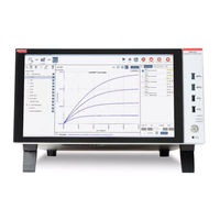
Keithley 4200-SCS Reference Manual (1719 pages)
Semiconductor Characterization System
Brand:
Keithley
| Category:
Test Equipment
| Size: 39.75 MB
Table of Contents
Table of Contents
7
Model 4200-SCS System Overview
22
Introduction
22
Embedded PC Policy
22
Software Features
24
Hardware Features and Capabilities
24
Model 4200-SCS Documentation Overview
28
Surveying the Documentation
28
Distinguishing Special Text Items in the Manuals
31
Shipment Contents
34
Inspection for Damage
34
Unpacking and Inspection
34
Introduction
34
Installation
34
Manual Package
35
Repacking for Shipment
35
System Connections
36
Connecting the Keyboard and Mouse (Optional)
36
Connecting GPIB Instruments
37
Connecting a Probe Station
38
Connecting a Printer
38
SMU Connections
39
Connecting a LAN
39
Triax Cables
40
Basic Connections
40
Test Fixtures
43
Mounting Preamps in a Probe Station
44
Pulsing: Source and Measure Hardware
45
Environmental Requirements
46
Shipping and Storage Environment
46
Operating Environment
46
Line Power
47
Powering the Model 4200-SCS
47
Power-Up Sequence
49
Warm-Up Period
49
Source-Measure Hardware
51
Introduction
53
Models 4200-SMU and 4210-SMU Overview
53
Basic SMU Circuit Configuration
53
Compliance Limit
55
Operating Boundaries
55
SMU Terminals and Connectors
61
Source Measure Unit (SMU) with Model 4200-PA Overview
62
Basic Smu/Preamp Circuit Configuration
63
Compliance Limit
63
Operating Boundaries
64
Preamp Terminals and Connectors
65
Preamp Mounting
67
Ground Unit (GNDU) Overview
69
Basic Characteristics
69
Basic Circuit Configurations
70
Ground Unit Terminals and Connectors
71
Connections and Configuration
73
LAN Connections/Usb Connections
74
Basic Source-Measure Connections
75
Introduction
75
Connection Considerations
76
SMU Connections
79
Preamp Connections
80
Using the Ground Unit
82
SMU Circuit COMMON Connections
86
Recommended Connecting Cables
87
Switch Matrix Connections
87
Test Equipment Connections
87
Prober Connections
91
Test Fixture Connections
91
Control and Data Connections
92
Safety Interlock Connections
92
Connections
94
Recommended Serial Cables
96
RS-232 Connector
96
Configuring COM1 Operation
97
LAN Connections
97
LAN Connectors
97
Recommended LAN Cables
98
USB Cables
98
USB Connections
98
Section 5 Source-Measure Concepts
99
Guarding
101
Guarding Overview
101
Introduction
101
Source-Measure Concepts
101
Guard Connections
102
Guarding Concepts
103
Test Fixture Guarding
104
Remote Sensing
105
Sensing Overview
105
Test Fixture Guarding
105
Local Sensing
106
Sense Selection
106
Sensing Concepts
107
Remote Sensing
108
Sensing Considerations
108
Model 4200-SMU Sink Boundaries
109
Sink Operating Boundaries
109
Sink Operation
109
Sink Overview
109
Model 4210-SMU Sink Boundaries
110
Source I, Measure V or I
110
Source-Measure Configurations
110
Source V, Measure I or V
111
Measure Only (V or I)
112
Source-Delay-Measure Cycle
113
Sweep Concepts
113
Sweep Waveforms
113
Current Source Stability
114
Making Stable Measurements
114
Single SMU Stability Considerations
114
Eliminating High-Frequency Oscillations
115
Eliminating Oscillations
115
Multiple SMU Stability Considerations
115
Voltage Source Stability
115
Eliminating Low Frequency Oscillations
116
Cable Leakage Currents
117
Leakage Currents
117
Low Current Measurements
117
Sources of Leakage Currents
117
Generated Currents
118
Offset Currents
118
Reducing Leakage Currents
118
Contamination and Humidity
120
Piezoelectric and Stored Charge Effects
120
Triboelectric Effects
120
Dielectric Absorption
121
Voltage Burden
121
Cable Capacitance
122
Noise and Source Impedance
122
Source Capacitance
122
Source Resistance
122
Electrostatic Interference
123
Interference
123
Performance of an Integrated Semiconductor Test System
123
Radio Frequency Interference
123
Ground Loops and Other SMU Grounding Considerations
124
Radio Frequency Interference
124
Section 6 Keithley Interactive Test Environment (Kite)
127
Keithley Interactive Test Environment (KITE)
127
Introduction
131
KITE Projects
131
KITE Interface
136
Overview of KITE
136
Project Navigator
138
Interactive Test Modules (Itms) and User Test Modules (Utms)
140
Enabling Real Time Plotting for Utms
142
Defining an ITM
144
Defining a UTM
145
Using the UTM GUI View
146
Viewing ITM or UTM Results Numerically: the Sheet Tab Data Worksheet
148
Viewing ITM or UTM Results Graphically: the Graph Tab
149
Developing and Using User Libraries for Utms
150
Developing Test Modules
150
Creating and Using User Libraries
152
Basic Test Execution
153
Project Navigator Checkboxes
153
Executing an Individual Test
154
Executing an Individual Test Sequence
155
Assigning a Site-Number Label to Individual Test and Test-Sequence Data
156
Executing an Entire Project Plan
156
Test Data
157
Multi-Site Project Plan Execution
159
Multi-Site Setup
159
Multi-Site Execution
160
Multi-Site Test Data
161
Project Components
163
Project Defined
163
Understanding KITE
163
Devices
164
Sites
164
Subsites
164
Tests
164
Project Plan
165
Project Structure
165
Initialization and Termination Steps
167
Site Plan
167
Subsite Plan
169
Device Plan
170
Interactive Test Module (ITM)
171
User Test Module (UTM)
172
Building a Completely New Project Plan
174
Building, Modifying, and Deleting a Project Plan
174
Defining the New Project Plan
175
Inserting Device Plans
175
Inserting the Itms
175
Inserting the Subsite Plans
175
Inserting the Utms
175
Modifying an Existing Project Plan
197
Saving the Project Plan
197
Opening an Existing Project Plan
198
Saving a Project Plan under a New Name
200
Adding and Deleting Initialization and Termination Steps
201
Adding, Rearranging, and Deleting Subsite Plans
202
Adding, Rearranging, and Deleting Device Plans
205
Rearranging and Deleting Itms and Utms
208
Deleting a Project Plan
210
Configuring the Project Plan Itms
212
Opening an ITM Window
213
Becoming Acquainted with the ITM Definition Tab
214
ITM Status Tab
216
Matching Definition Tab Terminal Connections to Physical Connections
217
Selecting the ITM Test Mode
218
Understanding the Mode Combo Box
218
Assigning/Reassigning Forcing Functions to the Device Terminals
219
Reviewing the Available Forcing Functions
219
Selecting Sweeping or Sampling Mode
219
Assigning Forcing Functions for a Completely New ITM
221
Reassigning Forcing Functions for an Existing Library ITM
223
Configuring SMU Forcing Functions/Measure Options Window
224
Opening a Forcing Functions/Measure Options Window
224
Reviewing a Typical Forcing Functions/Measure Options Window
225
Understanding the Forcing Function Area
225
Understanding the Instrument Information Area
225
The Forcingfunctionname Function Parameters Area
228
Understanding and Configuring the Measuring Options Area
252
Configuring the Speed and Timing Settings in the ITM Definition Tab
256
Speed Combo Box
257
Timing Window
258
Configuring Formulator Calculations
266
Saving the ITM Configuration
266
ITM Compliance Exit Conditions
267
Setting the ITM Compliance Exit Condition
267
Configuring the Utms
268
ITM Output Values
268
Opening a UTM Window
270
Connecting/Reconnecting the UTM to a User Library and Module
272
Configuring Formulator Calculations
273
Inputting the UTM Parameters
273
Saving the UTM Configuration
274
Submitting Devices, Itms, and Utms to Libraries
274
UTM Output Values
274
Submitting Devices to a Library
275
Submitting Tests to a Library
277
Copying Tests from a Library
280
Enabling Tests (Project Navigator Checkboxes)
283
Executing Project Plans, Subsite Plans, Device Plans, and Tests
283
Run' Execution of Project Plans
283
Run Execution of Individual Tests and Test Sequences
288
Run' Execution of Individual Subsite Plans
289
Run' Execution of Individual Device Plans
291
Append Execution of Tests, Test Sequences, and Project Plans
294
Specifying the Maximum Number of Append Worksheets
296
Performing an Append Execution
297
Repeating a Test
298
Test Data
298
Displaying and Analyzing Test Results
299
Stress Testing
299
Displaying and Analyzing Data Using the Sheet Tab
300
Opening a Sheet Tab
300
Understanding and Using the Data Worksheet of a Sheet Tab
302
Understanding the Data-Source Identifier
303
Saving a Worksheet
304
Understanding and Using Append Worksheets of a Sheet Tab
307
Understanding and Using the Calc Worksheet of a Sheet Tab
312
Understanding and Using the Settings Worksheet of a Sheet Tab
328
Accessing the Graph Tab Windows
330
Opening a Graph Tab
330
Viewing Data Using the Graph Tab
330
Defining the Data to be Graphed
334
Defining the Axis Properties of the Graph
338
Defining the Plot Properties of the Graph: Colors, Line Patterns, Symbols, Line Widths
349
Numerically Displaying Plot Coordinates Using Cursors
354
Viewing Plot Coordinates and Data Series Properties Using the Pointing Device (Mouse)
363
Visually Reading Plot Coordinates Using Cross Hairs
367
Performing On-Graph Line Fits
368
Displaying Test Conditions
389
Adding a Title, Legend, or Comment to the Graph
394
Changing Area Properties of the Graph
402
Changing the Size of a Graph
404
Changing the Position of a Graph
408
Identically Configuring the Graphs Resulting from One Test Executed at Multiple Sites
408
Saving a Graph
409
Resetting Certain Graph Properties to KITE Defaults
410
Appending Curves from Multiple Runs on a Single Graph
411
Analyzing Test Data Using the Formulator
413
Understanding the Formulator
414
Starting the Formulator
415
Becoming Familiar with the Formulator Window
416
Understanding the Formulator Functions
417
Formulator Function Reference
418
Identifying Data Analysis Requirements
437
Creating an Analysis Formula
438
Adding an Analysis Formula to the ITM or UTM
439
Executing an Analysis Formula
439
Viewing Analysis Results in the Sheet Tab Data Worksheet
440
Editing Formulas and Constants
441
Viewing Analysis Results in the Graph Tab
441
Deleting Formulator Formulas and Constants
442
Cycle Mode
443
Overview
443
Subsite Cycling
443
Perform the Following Steps to Select and Set the Number of Test Cycles to Perform
445
Segment Stress/Measure Mode
447
Stress/Measure Mode
447
AC Voltage Stressing
448
DC Voltage Stressing
448
Current Stressing
450
Testing
450
Combined Stressing and Testing
451
KDF User Tag Data
452
Storing Test Results in Exportable Keithley Data File (KDF) Format
452
Customizing KITE
462
Customizing Workspace Options
462
Specifying a Default Project
462
Specifying Environment Preferences
464
Customizing Directory Options
466
Specifying Execution Preferences
466
Specifying Which Test Library Directories Are to be Available to Projects
467
Customizing Graph Defaults
471
Specifying Which Device Library Directories Are to be Available to Projects
471
Custom GPIB Abort Options
472
Customizing the View
473
Messages Display Option
473
Project Navigator Display Options
473
Toolbar Display Options
473
Calibrating the System
475
Section 7 Keithley Configuration Utility (Kcon)
477
Keithley Configuration Utility (KCON)
477
Introduction
479
KCON Main Window
479
Configuration Navigator
480
File Menu
481
KCON Main Menu
481
File > Exit
482
File > Print Configuration
482
Filesave Configuration
482
Filesave Configuration as Web Page
482
Tools > Add External Instrument
482
Tools Menu
482
Tools > Delete External Instrument
485
Tools > Update DC Preamp and RPM Configuration
485
Tools > Validate Configuration
485
Tools > Formulator Constants
486
Help Menu
487
Helpgenerate Technical Support Files
487
Helpabout KCON
488
KI System Configuration Properties Window
488
System Configuration Properties
488
KI 4200 SCS Properties Window
489
System Properties Area
490
Instrument Cards Area
492
Communications Radio Buttons
493
GPIB Address Combo Box
493
Command Set Radio Buttons
494
Delimiter Radio Buttons
494
EOI Radio Buttons
494
Port Number Combo Box
494
KI 4200/4210 SMU Properties and Connections Tabs
495
KI 4200 Preamp Properties Tab
496
KI 4205 VPU Properties and Connections Tab
497
KI 4200 SCOPE Properties and Connections Tab
498
KI590 CV Analyzer Properties and Connections Tab
500
KI595 CV Analyzer Properties and Connections Tab
501
Keithley User Library Tool (KULT)
502
KI82 CV System Properties and Connections Tab
502
HP 4980 LCR Meter Properties and Connections Tab
503
HP 4294 LCR Meter Properties and Connections Tab
504
HP 8110 and HP 81110 Properties and Connections Tabs
505
Keithley User Library Tool (KULT)
505
KI 70X Switching Matrix Properties Tab
506
KI 7XXX Matrix Card Properties Tab
510
Probe Station Properties Tab
512
Section 8 Keithley User Library Tool (Kult)
517
Keithley User Library Tool (KULT)
520
KULT Window
520
KULT Window
521
Understanding the Module Identification Area
522
Understanding the Module Parameter Display Area
522
Parameters Tab Area
523
Understanding the Module Code Entry Area
523
Understanding the Tab Areas
523
Understanding the Terminating Brace Area
523
Data Type Field
524
Parameter Name Field
524
Default, Min, and Max Fields
525
I/O Field
525
Includes Tab Area
525
Description Tab Area
526
Build Tab Area
527
Understanding the Status Bar
527
File Menu
528
Understanding the Menus
528
Edit Menu
530
Help Menu
531
Options Menu
531
KULT Tutorials
532
Tutorial 1: Creating a New User Library and User Module
532
Naming a New User Library
533
Starting KULT
533
Naming a New User Module
534
Entering Parameters
535
Entering the Return Type
535
Entering User Module Code
535
Entering Header Files
537
Documenting the User Module
538
Compiling the User Module
539
Finding Code Errors
539
Saving the User Module
539
Building the User Library to Include the New User Module
541
Checking the User Module
541
Finding Build Errors
541
Entering the Vsweep User-Module Code
545
Entering the Vsweep User-Module Return Type
545
Naming New User Library and New Vsweep User Module
545
Tutorial 2: Creating a User Module that Returns Data Arrays
545
Entering the Vsweep User-Module Parameters
546
Entering the Vsweep User-Module Header Files
548
Checking the Vsweep User Module
549
Compiling and Building the Vsweep User Module
549
Documenting the Vsweep User Module
549
Saving the Vsweep User Module
549
Creating Vsweepbeep User Module Copying Existing User Module
551
Tutorial 3: Calling One User Module from Within Another
551
Compiling and Building the Vsweepbeep User Module
554
Specifying User Library Dependencies in Vsweepbeep User Module
554
Advanced KULT Features
555
Checking the Vsweepbeep User Module
555
Managing User Libraries
555
Controlling Where User Libraries Are Stored
556
Changing the Active User-Library Directory
559
Updating and Copying User Libraries Using KULT Command-Line Utilities
562
Performing Other KULT Tasks Using Command-Line Commands
564
Structuring Dependencies Hierarchically
567
Working with Interdependent User Modules and User Libraries
567
Building Dependent User Libraries in the Correct Order
571
Edit Locking
572
Understanding User Module Locking
572
Removing Locks that Remain after Interrupted Operation
573
Run-Time Locking
573
Creating a Debug Task
574
Debugging User Modules Using Microsoft Visual C
574
Loading a Debug Task
575
UTM GUI View
575
Creating a UTM GUI Definition Using the UTM GUI Editor
577
Enabling Access to the UTM GUI Editor
578
Using the UTM GUI Editor
579
Completing a Change
581
Example of Using the Editor
581
Groups
582
To Modify a Group
583
Selecting a GUI Image
584
Editing the Attributes for a Test Parameter
585
Control Type
586
Control Types
586
Displayed Group
586
Displayed Tooltips Field
586
Displayed Units Field
586
Help
586
Minimum, Maximum, and Default Value Fields
586
Editbox
587
Listbox
587
Checkbox Control
591
Optionbtn Control
592
Inputarray Control
593
Segarbconfig
596
Reset Defaults
605
UTM GUI Definition File Information
605
Copy or Move UTM GUI Definitions
606
LPT Library Function Reference
606
LPT Functions
607
Using Source Compliance Limits
607
LPT Functions for Smus and General Operations
612
LPT Functions for the Model
671
LPT Functions for the Models 4220-PGU and 4225-PMU
693
LPT Library Status and Error Codes
729
Cross-Platform Lptlib Compatibility
736
Lptlib and KITE Interaction Via Utms
736
S400/S600 Functions Not Supported by the Model 4200-SCS
742
Moving User Libraries: 4200-SCS to S400
743
Keithley External Control Interface (KXCI)
747
GPIB Standards
749
Introduction
749
Remote Control Overview (GPIB, Ethernet)
749
Communication Connections
750
Setting Remote Control Mode (GPIB Versus Ethernet)
751
KXCI Control Interface
752
Starting KXCI and the GPIB Command Interpreter
752
Understanding the KXCI User Interface
753
Understanding the Log File
754
Using KXCI
755
GPIB Command Set
757
GPIB Command Reference
767
System Mode Commands
767
User Mode Commands (US)
786
Commands Common to System and User Modes
790
4200 Extended Mode-Only Commands
794
Ethernet Command Reference
794
SMU Default Settings
794
System Mode SMU Default Settings
795
Data Format for System Mode Readings
796
Data Format for User Mode Readings
796
Output Data Formats
796
Status Byte
798
Status Byte and Serial Polling
798
Program 1: VAR1 and VAR2 Sweep (System Mode)
799
Sample Programs
799
Serial Polling
799
Waiting for SRQ
799
Program 2: Basic Source-Measure (User Mode)
801
Program 3: Retrieving Saved Data (System Mode)
802
GPIB Error Messages
803
Keithley Pulse Card KXCI Commands
803
Pulse Generator and Scope Commands
803
KXCI Commands to Control Scope Card
811
Scope Error Codes
839
KXCI CVU Commands
842
Code Examples
848
Calling KULT User Libraries Remotely
850
EX: Execute
850
UL: Usrlib
850
GN: Get Parameter (by Name)
851
GD - Get Description
852
GP: Get Parameter (by Number)
852
Systemutil User Library
853
Driver Functions
854
KXCI Ethernet Client Driver
854
System Administration
855
Embedded PC Policy
856
Introduction
856
Creating New User Accounts
857
Default User Accounts
857
Preconfigured User Accounts
857
Managing Multiple Users and Systems
858
Creating Additional User or Personal Directories
859
Default User Directory C:\S4200\Kiuser
859
System Directory C:\S4200\Sys
859
Sharing Libraries and Projects
861
BIOS Settings
863
Default Video Settings
863
Driving an External Monitor from a 4200-SCS with an Integrated FPD
863
Acronis True Image OEM
864
Placing KITE or KXCI in the Windows Startup Menu
864
System-Level Backup and Restore Software
864
Acronis True Image OEM
866
Image Restore to Factory Condition
866
Read and Write Permission Access to USB Ports
866
Pulse Source-Measure Concepts
869
Settings for Pulse Generator
872
Complement Mode
873
Current Limit
873
Full Arb Waveform
873
Segment ARB Waveform
879
Kiscopeulib UTM Descriptions
889
Basic Triggering
898
Triggering
898
Pulse-Measure Synchronization
899
Pulse Output Synchronization
901
Multi-Channel Synchronization with the Segment ARB Mode
904
Pulse Source-Measure Connections
906
Pulse Generator Connections
908
Scope Connections
908
Pulse Generator and Scope Connections
909
Multiple Pulse Generator and Scope Connections
910
Pulse Parameter Definitions
912
Pulse Period
913
Pulse Width
913
Duty Cycle
914
Pulse Delay
914
Interchannel Delay (Skew)
915
Transition Time
915
Jitter
916
Linearity (Deviation)
916
Pulse Levels
916
Distortion (Preshoot, Overshoot, and Ringing)
917
Settling Time
917
Dualpulseulib UTM Descriptions
918
PIV-Q User Libraries
918
Repeatability
918
Pulse Adapters, Cables, Hardware and PCU
960
Pulse Projects for Models 4200-PIV-A and 4200-PIV-Q
961
3-Port Power Divider
962
Model 4205-RBT (Remote Bias Tee) and Power Divider
962
Rbt
962
Using an RBT and Power Divider
963
Pulseiv-Complete and Demo-Pulseiv Projects
964
Theory of Operation for the 4200-PIV-A Package
966
PIV Tests
968
Cal_Pulseiv
978
Pulse IV UTM Descriptions
978
Qpulseiv-Complete Project
978
Vdsid_Pulseiv
980
Vdid_Pulse_Dc_Family_Pulseiv
982
Vgsid_Pulseiv
986
Vgid_Dc_Pulse_Pulseiv
988
Scopeshot_Cal_Pulseiv
991
Scopeshot_Pulseiv
993
Scopeshot_Pulseiv_Demo
995
Vdsid_Pulseiv_Demo
995
Vgsid_Pulseiv_Demo
995
Kpulse (for Keithley Pulse Generator Cards)
997
Kscope (for Models 4200-SCP2 and 4200-SCP2HR)
999
Kscope Graphical User Interface
1000
Configure Input Settings
1001
Configure Trigger Settings
1002
Configure Arm Settings
1003
Configure Calculate Settings
1004
Configure Measure Settings
1005
Configure the Hardware Settings
1006
Operate the Scope
1007
Multi-Frequency C-V Measurements (Model 4210-CVU)
1009
4210-CVU Card
1013
Introduction
1013
Measurement Overview
1013
Measurement Functions
1014
DC Bias Function and Sweep Characteristics
1015
Test Signal
1015
Force-Measure Timing
1016
Cables and Adapters
1017
Connections
1017
Test Connections
1019
Confidence Check
1023
Connection Compensation
1026
KCON System Configuration
1030
Properties & Connections Tab
1030
Properties Tab for the Switching Matrix
1031
Properties Tab for the Matrix Card
1033
Saving the Configuration
1035
C-V Project Plans
1036
Cvu_Bjt
1036
Cvu_Capacitor
1036
Cvu_Interconnectcap
1036
Cvu_Mobileion
1036
Cvu_Moscap
1036
Cvu_Mosfet
1036
Project Plans Overview
1036
Cvu_Nanowire
1130
Cvu_Pnjunction
1136
Cvu_Pvcell
1149
Default
1166
Running Project Plan Tests
1167
LPT Library Function Reference
1171
Asweepv
1172
Devclr
1173
Devint
1173
Dsweepf
1174
Dsweepv
1175
Forcev
1176
Getstatus
1176
Measf
1177
Meast
1177
Measv
1178
Measz
1178
Rangei
1179
Rtfary
1179
Setauto
1180
Setfreq
1180
Setlevel
1181
Setmode
1181
Smeasf
1182
Smeasfrt
1183
Smeast
1183
Smeastrt
1184
Smeasv
1184
Smeasvrt
1185
Smeasz
1185
Smeaszrt
1186
Sweepf
1187
Sweepv
1188
Programming Examples
1189
Using the 4210-CVU Card Switch Matrix
1191
Advertisement
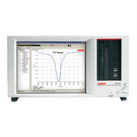
Keithley 4200-SCS User Manual (335 pages)
Semiconductor Characterization System
Brand:
Keithley
| Category:
Semiconductors
| Size: 26.35 MB
Table of Contents
Table of Contents
7
Getting Started
11
Installation and System Connections
13
Inspection for Damage
13
Manuals
13
Repacking for Shipment
13
Shipment Contents
13
Unpacking the Model 4200-SCS
13
Environmental Considerations
14
Operating Environment
14
Shipping and Storage Environment
14
Line Power
15
Line Power Connection
15
Powering up the 4200-SCS
15
Connecting the Keyboard and Mouse
16
Line Frequency Setting
16
System Connections
16
Warm-Up Period
16
Connecting GPIB Instruments
17
Connecting a Probe Station
18
Connecting a LAN
19
Connecting a Printer
19
Model 4200-SCS Hardware Overview
20
Basic Characteristics
20
Basic SMU Circuit Configuration
20
DC Source-Measure Unit (SMU)
20
Models 4200-SMU and 4210-SMU Overview
20
SMU Terminals and Connectors
22
Basic Smu/Preamp Circuit Configuration
23
SMU with Model 4200-PA Overview
23
DC Preamp
24
Preamp Terminals and Connectors
24
FORCE Terminal
25
Multi-Frequency Capacitance / Voltage Unit (CVU)
26
Measurement Overview
26
Model 4210-CVU Card
26
Preamp CONTROL Connector
26
SENSE Terminal
26
Measurement Functions
27
DC Bias Function and Sweep Characteristics
28
Test Signal
28
Force-Measure Timing
30
Pulse Cards
30
Bias Function
30
Sweep Function
30
About the Pulse Cards
31
Firmware Upgrade for the 4200
32
Standard Pulse
32
Segment ARB Waveform
33
Full Arb
34
Pulse Card Settings
35
3-Port Power Divider
36
Rbt
36
Remote Bias Tee (RBT) and 3-Port Power Divider
36
Using an RBT and Power Divider
37
SCP2 (Oscilloscope)
38
Scope Card Settings
39
Basic Characteristics
42
Basic Circuit Configurations
42
Ground Unit (GNDU)
42
Ground Unit Connections
42
Ground Unit DUT Connections
43
FORCE Terminal
44
Ground Unit Terminals and Connectors
44
Chassis Ground
45
COMMON Terminal
45
SENSE Terminal
45
Connecting Duts
46
Test Fixtures
46
Testing with Less than ±20 V
46
Advanced Connections
47
Probers
47
Testing with more than ±20 V
47
How to Run a Basic Test
48
Boot the System and Log in
48
Open KITE
48
Locate and Run the Vds-ID Test Module
50
Test Definition
51
Run Vds-ID Test
52
View and Save the Sheet Data
52
View and Save the Graph Data
53
Firmware Upgrade
55
Accessing the Release Notes
56
Section 2 Model 4200-Scs Software Environment
57
Model 4200-SCS Software Environment
57
KITE Project Structure
59
KITE Interface
59
Graphical User Interface
60
Project Navigator
61
Project Defined
63
Project Components
63
Devices
63
Sites
63
Subsites
63
Tests
63
Understanding KITE
59
Itms Versus Utms
64
Defining an ITM
65
Defining a UTM
66
Using the UTM GUI View
67
How to Create Your Own Itms
69
Understanding the ITM Definition Tab
69
Understanding the ITM Forcing Functions
69
Understanding Dual Sweep
71
Understanding Pulse Mode
72
How to Use the Definition Tab to Configure ITM Parameters
73
Match the Physical and Virtual Connections
73
Configuring Forcing Functions for each Device Terminal
74
Basic Test Execution
77
Project Navigator Check Boxes
77
Configuring Pulse Mode
77
Device Plan
78
Initialization and Termination Steps
78
Project Plan
78
Subsite Plan
78
Tests (Itms and Utms)
78
Executing an Individual Test
79
Running the Test
79
Selecting a Test
79
How to Display and Manage Test Results
80
Data File Management
80
Using File and Test-Result Directories
80
Default User Director: C:\S4200\Kiuser
81
Devices Subdirectory
81
Understanding Device Libraries
82
How to Create and Add a New Device
83
Projects Subdirectory
84
Tests Subdirectory
85
System Directory: C:\S4200\Sys
87
Usrlib Subdirectory
87
How to Manage Numeric Test Results in Sheet Tab
88
Displaying and Analyzing Data Using Sheet Tab
88
Opening a Sheet Tab
88
Understanding and Using the Data Worksheet of a Sheet Tab
90
Understanding the Formula Box of the Data Worksheet
90
Understanding the Data-Source Identifier
91
Saving a Worksheet
92
How to Manage Graphical Test Results in the Graph Tab
94
Opening a Graph Tab
94
Accessing the Graph Tab Windows
95
Opening the Graph Settings Menu
95
Understanding the Graph Settings Menu
96
Defining Data to be Graphed
98
Understanding Table Columns in the Graph Definition Window
98
Opening and Using the Graph Definition Window
99
Understanding Buttons in the Graph Definition Window
99
KITE Library Management
101
Submitting Devices, Itms, and Utms to Libraries
101
Submitting Devices to a Library
101
Submitting Tests to a Library
104
Section 3 Common Device Characterization Tests
107
Common Device Characterization Tests
107
Default Project Overview
110
4- Terminal N-MOSFET Tests
111
Three Terminal NPN BJT Tests
112
Two Wire Resistor Test
113
Diode Tests
114
Connections
115
Leveraging the Default Project
116
Copying Entire KITE Project
116
Copying Individual Tests Using the Test Library Manager
117
Changing KITE Startup Behavior
118
How to Perform an I-V Test on My Device
110
KITE ITM Configuration
119
How to Perform a C-V Test on My Device
119
Definition Tab
119
Terminal Settings
119
Forcing Functions and Measure Options
122
Selecting the Forcing Function
122
Setting the DC Bias Conditions
123
Setting the AC Drive Conditions
123
Measure Settings
123
Test Conditions
124
Advanced Settings (Terminal Properties)
124
Status
126
Compensation
126
CVU ITM Examples
127
CVU Voltage Bias
127
CVU Voltage Sweep
128
CVU Voltage List Sweep
129
CVU Frequency Sweep (Bias)
130
CVU Frequency Sweep (Step)
132
Introduction (PIV-A and PIV-Q)
133
What Is Pulse IV
134
Why Use Pulse IV
134
Pulse IV for CMOS: 4200-PIV-A
135
Target Applications and Test Projects for PIV-A
135
What Is the PIV-A Pulseiv Package
135
How to Perform a Pulsed I-V Test on My Device
133
4200-PIV-A Test Connections
136
Supplied Interconnect Parts
136
Supplied Tools
137
Model 8101- PIV Test Fixture
138
Prober Interconnect
139
DC Prober Interconnect
140
RF Prober Interconnect
141
PIV-A Interconnect Assembly Procedure
141
Using the Pulseiv-Complete Project for the First Time
144
Running Autocalscope
145
Running Pulseivcal
145
Running Vds-ID DC ITM
146
Running Vds-ID-Pulse UTM
147
Running Vds-ID-Pulse-Vs-DC UTM
148
Running Vgs-ID DC ITM
149
Running Vgs-ID-Pulse UTM
149
Running Vgs-ID-Pulse-Vs-DC UTM
150
Running Scope-Shot
151
Adjustable Parameters in Scopeshot_Cal_Pulseiv
151
Tips for Using Pulse IV
152
Comparing DC and Pulse Results
153
Pulse IV UTM Descriptions
155
Cal_Pulseiv
156
Vdsid_Pulseiv
157
Vdid_Pulse_Dc_Family_Pulseiv
159
Vgsid_Pulseiv
163
Vgid_Dc_Pulse_Pulseiv
165
Scopeshot_Cal_Pulseiv
169
Scopeshot_Pulseiv
170
Scopeshot_Pulseiv_Demo
172
How to Perform a Quiescent-Point Pulsed I-V Test (PIV-Q) on My Device
172
Vdsid_Pulseiv_Demo
172
Vgsid_Pulseiv_Demo
172
Q-Point Pulse IV - Model 4200-PIV-Q
172
What Is the PIV-Q Package
173
Target Applications and Test Projects
173
Connecting Devices for Stress / Measure Cycling
174
Overview of the Cycling-Related Tabs
175
How to Perform Reliability (Stress-Measure) Tests on My Device
174
Configuring Subsite Cycling
175
Configuring the Subsite Setup Tab
176
Step A: Enable Cycling
176
Step B: Choose the Mode of Cycling
176
Step C1: Specify Cycle Timing; Linear, Log or List (Stress / Measure Mode Only)
176
Step C2: Specify Number of Cycles (Cycle Mode Only)
178
Step D: Set Periodic Test Intervals (Stress / Measure Mode, Log Timing Only)
178
Step E: Update and Save the Subsite Setup Configuration
179
Configuring Device Stress Properties
180
Setting AC Stress Properties
181
How to Perform AC Stress for Wafer Level Reliability (WLR)
184
Device Stress Properties Configuration Notes
187
Segment Stress / Measure Mode
191
Segment ARB Stressing
191
Segment ARB Stressing
192
Segment Stress / Measure Mode Configuration
193
Configure Stress Counts
193
Configure Device Stress Properties
195
Subsite Cycling Data Sheets
197
Multiple Subsite Cycling
197
Cycle Mode Data Sheet
197
Settings Window
200
Executing Subsite Cycling
197
Subsite Cycling Graphs
202
Cycle Mode
202
Index
202
Stress/Measure Mode
203
Configuration Sequence for Subsite Cycling
204
How to Perform a Flash Memory Test on My Device
206
Introduction
206
Theory of Operation
206
Programming and Erasing Flash Memory
206
Endurance Testing
212
Disturb Testing
213
Using a Switch Matrix
214
Pulse Waveforms for NVM Testing
215
Using Kpulse to Create and Export Segment ARB Waveforms
215
Flash Connections
221
Direct Connection to Single DUT
226
Direct Connection to Array DUT for Disturb Testing
227
Switch Matrix Connection to Array DUT
228
Memory Projects
230
Nvm_Examples
232
Flash-NAND Tests
232
Flash-NOR Tests
236
Flash-Switch Tests
236
Running the Flash-NAND, Flash-NOR or Flash-Switch Project
239
Running any Flash Project for the First Time
239
Running the Program or Erase UTM
240
Running the Fast-Program-Erase UTM
242
Running the Vt-Maxgm ITM
243
Running the Setupdc UTM
243
Running the Conpin-Pulse or Conpin-DC UTM (Switch Projects Only)
244
Flashendurance-NAND Tests
245
Flashendurance-NOR Tests
251
Flashendurance-Switch Tests
251
Running a Flashendurance or Flashdisturb Project
252
Running Endurance or Disturb Looping
254
Flashdisturb Tests
255
Explanation of Flash UTM Parameters
257
Error Codes
259
Troubleshooting
260
No Pulse Output
260
How to Perform Charge Pumping
261
Voltage Levels Do Not Match Expected Values
261
How to Perform a Charge Trapping Test
262
Slow Single Pulse Charge Trapping High K Gate Stack
262
Charge Trapping Procedure
263
Keithley 4200-SCS Startup Manual (12 pages)
Brand:
Keithley
| Category:
Measuring Instruments
| Size: 0.3 MB
Advertisement
Advertisement
Related Products
Keithley 4200A-SCS
Keithley 4200A-SCS-PK3
Keithley 4200A
Keithley 4200A-SCS-PK1
Keithley 4210-MMPC-S
Keithley 485
Keithley 487
Keithley 414
Keithley 414C
Keithley 445
Keithley Categories
Measuring Instruments
Multimeter
Power Supply
Test Equipment
Switch
More Keithley Manuals
Login
Sign In
OR
Sign in with Facebook
Sign in with Google
Upload manual
Upload from disk
Upload from URL