Table of Contents

Subscribe to Our Youtube Channel
Related Manuals for Keithley 8009


Summary of Contents for Keithley 8009
- Page 1 Model 8009 Resistivity Test Fixture Instruction Manual 99 Washington Street Melrose, MA 02176 800.517.8431 TestEquipmentDepot.com Contains Operating and Servicing Information 8009-901-01 Rev. C A GREATER MEASURE OF CONFIDENCE...
- Page 3 OF REMOVAL AND INSTALLATION, LOSSES SUSTAINED AS THE RESULT OF INJURY TO ANY PERSON, OR DAMAGE TO PROPERTY. Keithley Instruments, Inc. • 28775 Aurora Road • Cleveland, Ohio 44139 • (216) 248-0400 • Fax: (216) 248-6168 CHINA: Holiday Inn Lido • Office Building 404C • Beijing, China, 100004 • 861-4362871 • 861-4362871 FRANCE: 3 Allée des Garays •...
- Page 4 Model 8009 Resistivity Test Fixture Instruction Manual ©2008, Keithley Instruments, Inc. Test Instrumentation Group All rights reserved. Cleveland, Ohio, U.S.A. May 2008, Third Printing Document Number: 8009-901-01 Rev. C...
-
Page 5: Safety Precautions
SAFETY PRECAUTIONS The following safety precautions should be observed before using this product and any associated instrumentation. Although some instruments and accessories would normally be used with non-hazardous voltages, there are situations where hazardous conditions may be present. This product is intended for use by qualified personnel who recognize shock haz- ards and are familiar with the safety precautions required to avoid possible injury. - Page 6 Chassis connections must only be used as shield connections for measuring cir- cuits, NOT as safety earth ground connections. If you are using a test fixture, keep the lid closed while power is applied to the device under test. Safe operation requires the use of a lid interlock. If a screw is present on the test fixture, connect it to safety earth ground using #18 AWG or larger wire.
-
Page 7: Specifications
Specifications Operating Voltages: 1kV Peak Source (safety banana plugs supplied with 6517). 200V Peak Measure (triax, 3-lug). 200V Peak Common mode. 0.1A Peak Test Current. 1VA. Volume Resistivity Range: 10 to 10 Ohm-cm. Surface Resistivity Range: 10 to 10 Ohm. Center Electrode: 50.8mm O.D. -
Page 8: Table Of Contents
Table of Contents Section 1 — General Information Introduction ..........1 Supplied accessories . - Page 9 Model 8009 resistivity test fixture ..... . . 6 Figure 2-2 Model 8009 schematic diagram ......7 Figure 2-3 Connecting the Model 6517 Electroemter/High Resistivity Meter to the Model 8009 test fixture .
- Page 10 List of Tables Section 4 — Maintenance Table 4-1 Model 8009 replaceable parts list ..... . . 22...
- Page 11 Blank page.
-
Page 12: Section 1 - General Information
General Information Introduction This packing list contains information on using the Model 8009 Resistivity Test Fixture. The Model 8009 allows volume resistivity measurements up to 10 ohm-cm or surface resistivity measurements up to 10 Ω. The test fixture is designed using a three-lug triax connector that allows simple connection to a Keithley Instruments Model 6517, 6517A, or Model 6517B Electrometer. -
Page 13: Safety Information
3-slot triaxial connectors. Used to connect the Model 8009 test fixture to the Model 6517 Electrometer. • 8007-GND-3: Safety ground wire with ground lug. Safety information Safety symbols and terms The following terms and symbols are found on the test equipment, or used in this packing list. - Page 14 6. After the test, set the voltage source to 0V and wait for the source to discharge before opening the lid of the test fixture. NOTE The Model 8009 Test Fixture includes a 10cm square, 1mm thick test sample. For maximum protection, the Model 8009 should always be stored with this sample between the elec-...
- Page 15 Blank page.
-
Page 16: Section 2 - Operation
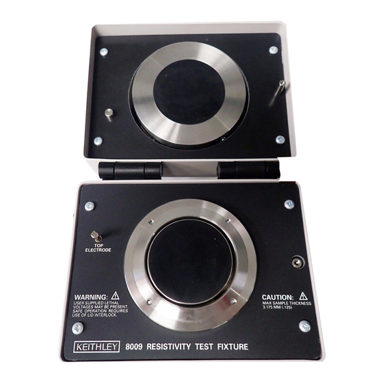
Then the test voltage value and measured current value are applied to the appropriate equation, and resistivity is calculated. The Model 8009 Resistivity Test Fixture is shown in Figure 2-1. The top view shows the inside of the test fixture where the sample is mounted. The front view shows the pushbutton switch that is used to select the desired resistivity test. -
Page 17: Figure 2-1 Model 8009 Resistivity Test Fixture
Figure 2-1 Model 8009 resistivity test fixture... -
Page 18: Figure 2-2 Model 8009 Schematic Diagram
Model 8009 schematic diagram Models 6517 and 6517B Electrometer/High Resistance Meters The Model 8009 Resistivity Fixture is designed to fully support the enhanced resistivity measurement capability of the Model 6517 and Model 6517B Electrometer/High Resistance Meters. Models 6517 and 6517B employ the ASTM D-257 measurement method, and display measurements in resistance, surface resistivity, or volume resistivity. -
Page 19: Astm Standard
Perform the following steps to mount the insulator sample in the Model 8009: 1. The top electrode in the Model 8009 is permanently attached to the top cover. A test sample is provided with the Model 8009 to protect the electrodes (this sample can be used for a functional check of the Model 8009). -
Page 20: Model 6517 Connections
Model 6517 Connections Refer to Figure 2-3 to connect the Model 6517 to the Model 8009 test fixture. The triax cable and the Model 6517-ILC-3 interlock cable are supplied with the Model 8009. Note that the ground link on the Model 6517 must be removed. -
Page 21: Meter To The Model 8009 Test Fixture
(both supplied with the Model 8009) is connected as shown in Figures 2-3 and 2-4. Whenever the lid of the Model 8009 is open, the Model 6517 or Model 6517B will go into standby, thus removing power from the test fixture. -
Page 22: Test Voltage
Typically specified test voltages to be applied to the insulator sample are 100V, 250V, 500V and 1000V. Higher test voltages are sometimes used, however the maximum test voltage that may be applied to the Model 8009 is 1000V. The most frequently used test voltages are 100V and 500V. The Keithley Instruments Model 6517 can provide test voltages up to 1000V. -
Page 23: Resistivity Measurement Procedure
If thickness is not known, use calipers to measure it. Calipers will provide a precise measurement. 1. Mount the insulator sample in the Model 8009 test fixture. See paragraph 2.3 for detailed information. 2. Close the lid of the test fixture, secure the latch and set the RESISTIVITY pushbutton switch for the desired test (SURFACE or VOLUME). -
Page 24: Section 3 - Derivation Of Resistivity Equations
Calculating resistivity The following equations used to calculate volume and surface resistivity are based on the physical dimensions of the electrodes of the Model 8009. Section 3.4, Derivation of Resistivity Equations, explains how these equations are derived. - Page 25 Volume Resistivity: Volume resistivity is defined as the electrical resistance through a one-centimeter cube of insulating material and is expressed in ohm- centimeters. Likewise, the electrical resistance through a one-inch cube of insulating material is expressed as ohm-inches. Volume resistivity (ρ) is measured by applying a voltage potential across opposite sides of the insulator sample, measuring the resultant current through the sample (see Figure 3-1), and then performing one of the following calculations:...
-
Page 26: Resistivity Nomographs
Resistivity nomographs With test voltage and measured current (and sample thickness for volume resistivity) known, resistivity can be approximated by using the appropriate nomograph. Figure 3-2 shows the nomograph for surface resistivity and Figure 3-3 shows the nomograph for volume resistivity. Surface Resistivity: The surface resistivity nomograph (Figure 3-2) is made up of three scales;... - Page 27 Volume Resistivity: The volume resistivity nomograph (Figure 3-3) is made up of four scales and a Graph Line. The four scales include; thickness (in cm) and current. Perform the following steps to determine volume resistivity: 1. Plot the average sample thickness (in cm) on the thickness scale. 2.
-
Page 28: Derivation Of Resistivity Equations
A is the effective area of the guarded electrode for the particular electrode arrangement employed. For the Model 8009, which uses circular electrodes, A is calculated as follows: (Equation 2) ------ - π... - Page 29 By using the calculated values for A, volume resistivity (Equation 1) looks like this: 22.9 ρ --------- - R 3.55 ρ --------- - R Where: t is the average thickness of the sample in centimeters. is the average thickness of the sample in inches. Volume resistance (R) is derived by dividing the applied test voltage (V) by the subsequent measured current (I).
-
Page 30: Figure 3-4 Electrode Dimensions
For the Model 8009, which uses circular electrodes, P is calculated as follows: P = D π Where: D , which is the effective diameter of the guarded electrode (see Figure 3-1), is 2.125 inches. Thus, P = 2.125π By substituting the values for g and P into Equation 3, it then looks like this:Sur- 2.125π... - Page 31 Blank page.
-
Page 32: Section 4 - Maintenance
Replaceable parts Table 4-1 lists the replaceable parts that are available for the Model 8009. These parts can be obtained directly from Keithley Instruments, Inc. When ordering parts, be sure to indicate the Model number (8009), serial number, and the Keithley Instruments part number. - Page 33 Table 4-1 Model 8009 replaceable parts list Keithley Instruments Description Part Number ASSY, 3LUG TRIAX CABLE 7078-308-3C BOTTOM PLATE 8009-302A BUSHING 14782G 6517-ILC-3 CABLE ASSEMBLY 6517-330A 6517B-ILC-3 CABLE ASSEMBLY CA-509A CENTER ELECTRODE 8009-305A COMPRESSION SPRING SP-7-1 COND RUBBER CENTER 8009-307A...
- Page 34 Service Form Model No. Serial No. Date Name and Telephone No. Company List all control settings, describe problem and check boxes that apply to problem. Intermittent Analog output follows display Particular range or function bad; specify: IEEE failure Obvious problem on power-up Batteries and fuses are OK Front panel operational All ranges or functions are bad...
Need help?
Do you have a question about the 8009 and is the answer not in the manual?
Questions and answers