Table of Contents
Advertisement
Quick Links
Download this manual
See also:
Instruction Manual
Advertisement
Table of Contents

Subscribe to Our Youtube Channel
Related Manuals for Keithley 8009


Summary of Contents for Keithley 8009
-
Page 1: Instruction Manual
Model 8009 Resistivity Test Fixture Instruction Manual 8009-901-01 Rev. D / May 2019 *P8009-901-01D* 8009-901-01D... - Page 2 Model 8009 Resistivity Test Fixture Instruction Manual...
- Page 3 All rights reserved. Any unauthorized reproduction, photocopy, or use of the information herein, in whole or in part, without the prior written approval of Keithley Instruments, LLC, is strictly prohibited. These are the original instructions in English. All Keithley Instruments product names are trademarks or registered trademarks of Keithley Instruments, LLC.
-
Page 4: Table Of Contents
Table of contents Getting started ......................1-1 Introduction .......................... 1-1 Features ..........................1-1 Accessories .......................... 1-2 Cleaning ..........................1-2 Operation ........................2-1 Operation overview ......................2-1 ASTM standard ......................... 2-4 Specimen mounting ........................2-4 Connections ......................... 2-4 6517 connections ........................2-5 6517B connections ........................ -
Page 6: Safety Precautions
Keithley products are designed for use with electrical signals that are measurement, control, and data I/O connections, with low transient overvoltages, and must not be directly connected to mains voltage or to voltage sources with high transient overvoltages. - Page 7 (note that selected parts should be purchased only through Keithley to maintain accuracy and functionality of the product). If you are unsure about the applicability of a replacement component, call a Keithley office for information.
-
Page 9: Getting Started
Features ................... 1-1 Accessories ................1-2 Cleaning ................... 1-2 Introduction The Model 8009 Resistivity Test Fixture allows volume resistivity measurements up to 10 Ω-cm or surface resistivity measurements up to 10 Ω. The test fixture is designed using a three-lug triaxial connector that allows simple connection to a Keithley Instruments Model 6517, 6517A, or 6517B Electrometer. -
Page 10: Accessories
Safety ground wire with ground lug Cleaning The 8009 electrodes should be periodically cleaned with methanol or other suitable solvent. The connectors should also be kept clean to prevent leakage when measuring low-level current. When not in use, keep the supplied protective spacer installed between the electrodes. This will help prevent the surfaces of the electrodes from getting nicked and scratched. -
Page 11: Operation
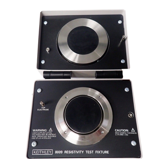
The 8009 is shown in following figure. The top view shows the interior of the test fixture where the specimen is mounted. The front view shows the pushbutton switch that is used to select the desired... - Page 12 Section 2: Operation Model 8009 Resistivity Test Fixture Instruction Manual Figure 1: 8009 text fixture 8009-901-01 Rev. D / May 2019...
- Page 13 Model 8009 Resistivity Test Fixture Instruction Manual Section 2: Operation The following figure shows a schematic diagram of the 8009. Note that the test fixture is externally connected to the electrode using a three-lug female triaxial connector. This connector will mate directly to the 6517 using the 6517-ILC-3 cable or to a 6517B using the 6517B-ILC-3 cable.
-
Page 14: Astm Standard
1. Remove the protective spacer. The top electrode in the 8009 is permanently attached to the top cover. A protective spacer is provided with the 8009 to protect the electrodes (this spacer can be used for a functional check of the 8009). -
Page 15: Connections
6517-ILC-3 or the 6517B-ILC-3 interlock cable (both supplied with 8009) is connected as shown in the following figures Whenever the lid of the 8009 is open, the 6517 or 6517B goes into standby, thus removing power from the test fixture. -
Page 16: 6517B Connections
Figure 3: Connecting a 6517 to the 8009 6517B connections Refer to the following figure to connect the 6517B to the 8009 test fixture. The triaxial cable and the 6517B-ILC-3 interlock cable are supplied with the 8009. Note that the ground link on the 6517B must be removed. -
Page 17: Test Voltage
Typically, specified test voltages to be applied to the specimen are 100 V, 250 V, 500 V, and 1000 V. The maximum test voltage that can be applied to the 8009 is 1000 V. The most frequently used test voltages are 100 V and 500 V. The 6517 can provide test voltages up to 1000 V. -
Page 18: Current Measurement Range And Compliance Limit
Section 2: Operation Model 8009 Resistivity Test Fixture Instruction Manual Current measurement range and compliance limit To make the most accurate resistivity measurement, the 6517 must be on the most sensitive (optimum) current measurement range. Place the 6517 in autorange to do this. - Page 19 6517-ILC-3 or the 6517B-ILC-3 interlock cable (both supplied with 8009) is connected as shown in the following figures Whenever the lid of the 8009 is open, the 6517 or 6517B goes into standby, thus removing power from the test fixture.
-
Page 20: Derivation Of Resistivity Equations
Calculating resistivity The following equations are used to calculate volume and surface resistivity. They are based on the physical dimensions of the electrodes of the 8009. For more information on how these equations are derived, see Derivation of resistivity equations... -
Page 21: Volume Resistivity
Section 3: Derivation of resistivity equations Model 8009 Resistivity Test Fixture Instruction Manual Figure 5: Basic measurement techniques Volume resistivity Volume resistivity is the electrical resistance through a 1 cm cube of insulating material and is expressed in ohm-centimeters. Likewise, the electrical resistance through a 1 inch cube of insulating material is expressed as ohm-inches. -
Page 22: Surface Resistivity
Model 8009 Resistivity Test Fixture Instruction Manual Section 3: Derivation of resistivity equations Where: ρ is the volume resistivity of the specimen V is the applied voltage for the electrometer is the average thickness of the specimen in centimeters is the average thickness of the specimen in inches... -
Page 23: Resistivity Nomographs
Section 3: Derivation of resistivity equations Model 8009 Resistivity Test Fixture Instruction Manual Resistivity nomographs With test voltage, measured current, and specimen thickness for volume resistivity known, resistivity can be approximated by using the appropriate nomograph. The following volume and surface resistivity figures show the nomograph for surface resistivity and the nomograph for volume resistivity. -
Page 24: Surface Resistivity
Model 8009 Resistivity Test Fixture Instruction Manual Section 3: Derivation of resistivity equations Figure 6: Volume resistivity nomograph Surface resistivity The surface resistivity nomograph is made up of three scales: voltage, resistivity, and current. To determine resistivity: 1. Plot the test voltage value on the voltage scale. -
Page 25: Resistivity Equations
Section 3: Derivation of resistivity equations Model 8009 Resistivity Test Fixture Instruction Manual Figure 7: Surface resistivity nomograph Resistivity equations The ASTM standard states that volume resistivity (ρ) shall be calculated as follows: Where: A is the effective area of the guarded electrode for the electrode arrangement... - Page 26 Model 8009 Resistivity Test Fixture Instruction Manual Section 3: Derivation of resistivity equations For the 8009, which uses circular electrode, A is calculated as follows: Where D , which is the effective diameter of the guarded electrode, is 5.40 cm (2.123 in.), as...
- Page 27 P is the effective perimeter of the guarded electrode for the particular electrode arrangement employed For the 8009, which uses circular electrodes, P is calculated as follows: Where: , which is the effective diameter of the guarded electrode, is 2.125 inches, see the figure below.
- Page 28 Model 8009 Resistivity Test Fixture Instruction Manual Section 3: Derivation of resistivity equations Surface resistance (R) is calculated by dividing the applied test voltage (V) by the subsequent measured content (I). By substituting R with V/I, the following equation is used to calculate surface resistivity is known.
- Page 29 All Keithley trademarks and trade names are the property of Keithley Instruments. All other trademarks and trade names are the property of their respective companies. Keithley Instruments Corporate Headquarters • 28775 Aurora Road • Cleveland, Ohio 44139 • 440-248-0400 • Fax: 440-248-6168 • 1-800-935-5595 • tek.com/keithley 12/17...
Need help?
Do you have a question about the 8009 and is the answer not in the manual?
Questions and answers