Juniper PTX5000 Hardware Manual
Packet transport router
Hide thumbs
Also See for PTX5000:
- Quick start manual (82 pages) ,
- Hardware manual (320 pages) ,
- Hardware manual (721 pages)

Subscribe to Our Youtube Channel
Related Manuals for Juniper PTX5000


Summary of Contents for Juniper PTX5000
- Page 1 PTX5000 Packet Transport Router Hardware Guide Modified: 2017-09-21 Copyright © 2017, Juniper Networks, Inc.
- Page 2 END USER LICENSE AGREEMENT The Juniper Networks product that is the subject of this technical documentation consists of (or is intended for use with) Juniper Networks software. Use of such software is subject to the terms and conditions of the End User License Agreement (“EULA”) posted at http://www.juniper.net/support/eula/.
-
Page 3: Table Of Contents
PTX5000 Craft Interface Description ........16... - Page 4 PTX5000 High Capacity AC PSM ........55...
- Page 5 PTX5000 Control Board Description ........83...
- Page 6 PTX5000 Physical Specifications ........
- Page 7 Overview of Installing the PTX5000 Packet Transport Router ....155 PTX5000 Installation Safety Guidelines ....... . 156 General Installation Safety Guidelines .
- Page 8 PTX5000 Field-Replaceable Units ........259...
- Page 9 Replacing a PTX5000 Craft Interface ........263...
- Page 10 Removing a PTX5000 AC PSM ........
- Page 11 Replacing a PTX5000 Control Board ........401...
- Page 12 Removing a PTX5000 PIC Cable ........439...
- Page 13 Maintaining the PTX5000 Fan Trays ........483...
- Page 14 Packing the PTX5000 Packet Transport Router for Shipment ....576 Packing PTX5000 Components for Shipment ......577...
- Page 15 PTX5000 Agency Approvals ........
- Page 16 PTX5000 Packet Transport Router Hardware Guide Copyright © 2017, Juniper Networks, Inc.
- Page 17 Chassis Components and Descriptions ....... 11 Figure 3: Front View of the PTX5000 Chassis ......12 Figure 4: Rear View of the PTX5000 Chassis .
- Page 18 PTX5000 Packet Transport Router Hardware Guide Figure 34: High Capacity Single-PhaseAC PDU Components ....54 Figure 35: AC PSM ..........55 Figure 36: High Capacity AC PSM .
- Page 19 Installing the Router into a Rack ........173 Figure 82: Loading the PTX5000 onto the Lift ......176 Figure 83: Installing the PTX5000 in an Open-Frame Rack .
- Page 20 PTX5000 Packet Transport Router Hardware Guide Figure 103: Installing a 120-A DC Input Power Tray ......210 Figure 104: Removing the Metal Retaining Bracket from a Three-Phase Delta AC PDU .
- Page 21 Tray ............301 Copyright © 2017, Juniper Networks, Inc.
- Page 22 PTX5000 Packet Transport Router Hardware Guide Figure 179: Connecting the DC Source Power Cable Lugs to a 120-A Input Power Tray ............302 Figure 180: Installing a 120-A Input Power Tray .
- Page 23 Figure 250: Installing a Routing Engine CompactFlash Card ....395 Figure 251: Removing an SSD Drive From a RE-DUO-C2600-16G ... . 397 Copyright © 2017, Juniper Networks, Inc. xxiii...
- Page 24 Figure 280: Removing a SIB from the PTX5000 ......461 Figure 281: Installing a SIB into the PTX5000 ......461 Figure 282: Removing an FPC from the PTX5000 .
- Page 25 Electrical Safety Guidelines and Warnings ......609 Figure 315: Placing a Component into an Antistatic Bag ....612 Copyright © 2017, Juniper Networks, Inc.
- Page 26 PTX5000 Packet Transport Router Hardware Guide xxvi Copyright © 2017, Juniper Networks, Inc.
- Page 27 Table 5: SIB LEDs on the PTX5000 Craft Interface ......20 Table 6: PTX5000 Host Subsystem LEDs ....... 20 Table 7: PTX5000 CCG LEDs .
- Page 28 Table 35: PTX5000 Routing Engines ........
- Page 29 Rear Support Bracket ........165 Table 76: Mounting Hole Locations for Installing a PTX5000 in a Four-Post Rack .
- Page 30 PTX5000 Packet Transport Router Hardware Guide Table 93: Troubleshooting FPC LEDs ........528 Table 94: Troubleshooting Power Distribution Unit Alarms .
-
Page 31: About The Documentation
® To obtain the most current version of all Juniper Networks technical documentation, see the product documentation page on the Juniper Networks website at http://www.juniper.net/techpubs/ If the information in the latest release notes differs from the information in the documentation, follow the product Release Notes. -
Page 32: Table 1: Notice Icons
PTX5000 Packet Transport Router Hardware Guide Table 1: Notice Icons Icon Meaning Description Informational note Indicates important features or instructions. Caution Indicates a situation that might result in loss of data or hardware damage. Warning Alerts you to the risk of personal injury or death. -
Page 33: Documentation Feedback
We encourage you to provide feedback, comments, and suggestions so that we can improve the documentation. You can provide feedback by using either of the following methods: Online feedback rating system—On any page of the Juniper Networks TechLibrary site , simply click the stars to rate the content, http://www.juniper.net/techpubs/index.html and use the pop-up form to provide us with information about your experience. -
Page 34: Requesting Technical Support
7 days a week, 365 days a year. Self-Help Online Tools and Resources For quick and easy problem resolution, Juniper Networks has designed an online self-service portal called the Customer Support Center (CSC) that provides you with the following features: Find CSC offerings: http://www.juniper.net/customers/support/... - Page 35 About the Documentation For international or direct-dial options in countries without toll-free numbers, see http://www.juniper.net/support/requesting-support.html Copyright © 2017, Juniper Networks, Inc. xxxv...
- Page 36 PTX5000 Packet Transport Router Hardware Guide xxxvi Copyright © 2017, Juniper Networks, Inc.
-
Page 37: Overview
Cooling System Components and Descriptions on page 27 Power System Components and Descriptions on page 33 Host Subsystem Components and Description on page 75 Switch Fabric Components and Descriptions on page 91 Interface Module Components and Descriptions on page 95 Copyright © 2017, Juniper Networks, Inc. - Page 38 PTX5000 Packet Transport Router Hardware Guide Copyright © 2017, Juniper Networks, Inc.
-
Page 39: System Overview And Architecture
PTX5000 Packet Transport Router Description The PTX5000 Packet Transport Router is designed for large networks and network applications, such as those supported by ISPs. The PTX5000 accommodates up to eight Flexible PIC Concentrators (FPCs), each of which can be configured with a variety of network media types. -
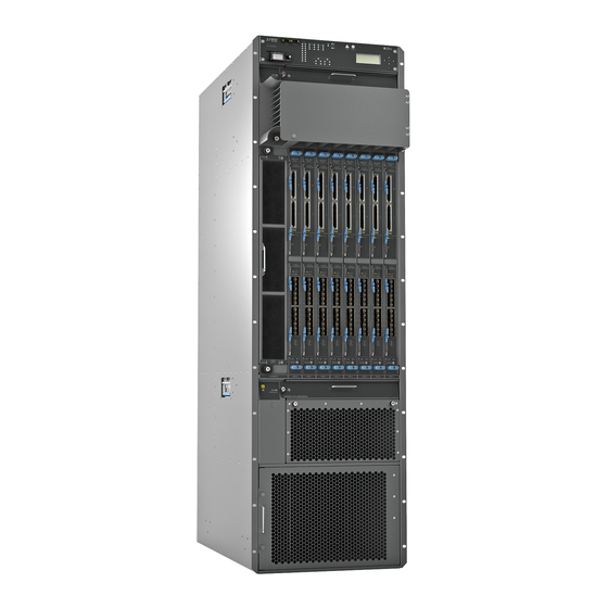
Page 40: Figure 1: Front View Of The Ptx5000
PTX5000 Packet Transport Router Hardware Guide Figure 1: Front View of the PTX5000 1— Front-mounting flange 6— FPCs and PICs 2— Craft interface 7— ESD point 3— Upper horizontal fan tray 8— Lower horizontal fan tray 4— Cable management system 9—... -
Page 41: Ptx5000 Hardware Component Overview
PTX5000 System Architecture Description on page 9 Documentation PTX5000 Chassis Description on page 11 Overview of Installing the PTX5000 Packet Transport Router on page 155 PTX5000 Hardware Component Overview The PTX5000 supports the components in Table 3 on page 6 listed in alphabetic order. -
Page 42: Table 3: Ptx5000 Hardware Components
PTX5000 Packet Transport Router Hardware Guide Table 3: PTX5000 Hardware Components Component Model Number Hardware Label CLI Output Description Cable management system – – – “PTX5000 Cable Management System” on page 15 Centralized Clock Generator CCG-PTX Clock Generator “PTX5000 (CCG) - Page 43 Chapter 1: System Overview and Architecture Table 3: PTX5000 Hardware Components (continued) Component Model Number Hardware Label CLI Output Description FPC-PTX-P1-A “PTX5000 FPC FPC-PTX-P1-A Description” on page 95 FPC2-PTX-P1A FPC2-PTX-P1A FPC E FPC3-PTX-U2 FPC3-PTX-U2 FPC-P1 FPC3-PTX-U3 FPC3-PTX-U3 FPC-P2 FPC-BLANK –...
-
Page 44: Ptx5000 Component Redundancy
PTX5000 Component Redundancy on page 8 PTX5000 Component Redundancy The PTX5000 is designed so that no single point of failure can cause the entire system to fail. The following major hardware components are redundant: Switch Interface Boards (SIBs)—The PTX5000 has nine SIBs. All nine SIBs are active and can sustain full throughput rate. -
Page 45: Ptx5000 System Architecture Description
(PDUs), located at the lower rear of the chassis in slots on the right and PDU0 on the left. The PDUs are hot-removable and hot-insertable. When the PTX5000 PDU1 is operating normally and both PDUs are switched on, load sharing between them occurs automatically. -
Page 46: Ptx5000 Packet Forwarding Engine Architecture
Packet Forwarding Engines—These high-performance, ASIC-based components provide packet forwarding, route lookups, and Layer 2 and Layer 3 packet switching. See “PTX5000 Packet Forwarding Engine Architecture” on page 10 for more information. The Routing Engines and the Packet Forwarding Engines perform their primary tasks independently, but communicate through multiple links. -
Page 47: Chassis Components And Descriptions
PTX5000 Centralized Clock Generator Description on page 23 PTX5000 Centralized Clock Generator LEDs on page 24 PTX5000 Chassis Description The PTX5000 Packet Transport Router chassis is a rigid sheet metal structure that houses all the other hardware components (see Figure 3 on page 12 Figure 4 on page 13). -
Page 48: Figure 3: Front View Of The Ptx5000 Chassis
PTX5000 Packet Transport Router Hardware Guide WARNING: The packet transport router must be connected to earth ground during normal operation. Figure 3: Front View of the PTX5000 Chassis 1— Front-mounting flange 6— FPCs and PICs 2— Craft interface 7— ESD point 3—... -
Page 49: Figure 4: Rear View Of The Ptx5000 Chassis
Chapter 2: Chassis Components and Descriptions Figure 4: Rear View of the PTX5000 Chassis 1— Center-mounting bracket 6— Control Board and Routing Engine 2— Air exhaust 7— ESD points 3— Centralized Clock Generators (CCGs) 8— Power distribution units (PDUs) 4—... -
Page 50: Ptx5000 Midplane Description
Documentation PTX5000 Packet Transport Router Description on page 3 PTX5000 Physical Specifications on page 116 Rack Requirements for the PTX5000 Packet Transport Router on page 119 PTX5000 Chassis Grounding Cable and Lug Specifications on page 112 PTX5000 Midplane Description The midplane is located in the center of the chassis and forms the rear of the Flexible PIC Concentrator (FPC) card cage. -
Page 51: Ptx5000 Cable Management System
All the cables from one FPC are routed to one channel. The cables are routed from the cable management system to the left side of the PTX5000. The front cable management system adds 3.8 in. (9.7 cm) to the depth of the chassis. -
Page 52: Ptx5000 Craft Interface Description
The craft interface allows you to view status and troubleshooting information at a glance and to perform many system control functions. It is hot-insertable and hot-removable. The craft interface is located at the upper front of the PTX5000 Packet Transport Router. Craft Interface Front Panel on page 16... -
Page 53: Craft Interface Lcd
To add a message that alternates every 2 seconds with the default status messages, use the command. set chassis display message Copyright © 2017, Juniper Networks, Inc. -
Page 54: Alarm Mode
Menu button Enter button Four arrow buttons for scrolling up or down, and left or right Related PTX5000 Hardware Component Overview on page 5 Documentation PTX5000 Craft Interface LEDs on page 18 PTX5000 Craft Interface LEDs Figure 9 on page 19 shows the craft interface LEDs. -
Page 55: Craft Interface Alarm Leds
The LCD display on the craft interface reports the cause of the alarm. A condition that causes an alarm LED to light also activates the corresponding alarm relay contact on the craft interface. Table 4 on page 20 describes the alarm LEDs. Copyright © 2017, Juniper Networks, Inc. -
Page 56: Craft Interface Sib Leds
PTX5000 Packet Transport Router Hardware Guide Table 4: Alarm LEDs on the PTX5000 Craft Interface Shape Color State Description On steadily Critical alarm LED—Indicates a critical condition that can cause the packet transport router to stop functioning. Possible causes include component removal, failure, or overheating. -
Page 57: Ccg Leds
Chapter 2: Chassis Components and Descriptions Table 6: PTX5000 Host Subsystem LEDs (continued) Label Color State Description Green On steadily Host subsystem is online and is functioning normally. – Host subsystem is offline or absent. FAIL On steadily Host subsystem has failed. -
Page 58: Power Distribution Unit Leds
PTX5000 Packet Transport Router Hardware Guide Power Distribution Unit LEDs LED for each power distribution unit is located on the craft interface below the host subsytem LEDs. The two LEDs are labeled Table 9: Power Distribution Unit LEDs Colour State... -
Page 59: Ptx5000 Centralized Clock Generator Description
LCD, CLI, and PSM LEDs on the PSM. – The PSM is offline or absent. The PSMs are offline or absent. Related PTX5000 Hardware Component Overview on page 5 Documentation PTX5000 Craft Interface Description on page 16 PTX5000 Centralized Clock Generator Description CCG Slots on page 23... -
Page 60: Ptx5000 Centralized Clock Generator Leds
PTX5000 Hardware Component Overview on page 5 Documentation PTX5000 Centralized Clock Generator LEDs on page 24 Troubleshooting the PTX5000 Centralized Clock Generators on page 507 PTX5000 Centralized Clock Generator LEDs Table 12 on page 24 describes the functions of the CCG LEDs.Table 13 on page 25... -
Page 61: Table 13: Ccg Port Leds
– The CCG has not detected a failure or is not powered on. Related PTX5000 Centralized Clock Generator Description on page 23 Documentation Troubleshooting the PTX5000 Centralized Clock Generators on page 507 Copyright © 2017, Juniper Networks, Inc. - Page 62 PTX5000 Packet Transport Router Hardware Guide Copyright © 2017, Juniper Networks, Inc.
-
Page 63: Cooling System Components And Descriptions
CHAPTER 3 Cooling System Components and Descriptions PTX5000 Cooling System Description on page 27 PTX5000 Cooling System Description The cooling system components work together to keep all components within the acceptable temperature range. The host subsystem monitors the temperature of the components. -
Page 64: Figure 11: Vertical Fan Tray
PTX5000 Packet Transport Router Hardware Guide Figure 11: Vertical Fan Tray FAN TRA VER TIC Cooling zone 1—The upper and lower horizontal fan trays, each Fan Tray 1 Fan Tray 2 of which contain six fans, cool the components installed in the front card cage (FPCs and PICs), and the CCGs. -
Page 65: Airflow
Rear Fantray Air intake Zone 1 Power supply air intake Air Filters The cooling system contains three air filters: One air filter is located inside the vertical fan tray (Figure 15 on page 30). Copyright © 2017, Juniper Networks, Inc. -
Page 66: Figure 15: Vertical Fan Tray Air Filter
PTX5000 Packet Transport Router Hardware Guide Figure 15: Vertical Fan Tray Air Filter One air filter is located below the lower horizontal fan tray (Figure 16 on page 30). Figure 16: Horizontal Fan Tray Air Filter One air filter is located inside the door for the power supply modules (Figure 17 on page 31). -
Page 67: Power Supply Cooling System
Related PTX5000 Hardware Component Overview on page 5 Documentation PTX5000 Clearance Requirements for Airflow and Hardware Maintenance on page 115 Maintaining the PTX5000 Air Filters on page 482 Maintaining the PTX5000 Fan Trays on page 483 Troubleshooting the PTX5000 Cooling System on page 509... - Page 68 PTX5000 Packet Transport Router Hardware Guide Copyright © 2017, Juniper Networks, Inc.
-
Page 69: Power System Components And Descriptions
PTX5000 DC Power Distribution Unit on page 33 PTX5000 DC Power Distribution Unit DC PDUs Supported on the PTX5000 The PTX5000 supports the DC power distribution units (PDUs) in Table 14 on page Table 14: DC PDUs Supported on the PTX5000... -
Page 70: Figure 18: 60-A Dc Pdu
PTX5000 Packet Transport Router Hardware Guide High Capacity DC PDU Description on page 37 PTX5000 DC Power Supply Module on page 40 Normal Capacity 60-A DC PDU Components NOTE: The 60-A DC PDUs do not have circuit breakers. Figure 18 on page 34 shows the 60-A DC PDU. -
Page 71: Figure 19: 60-A Dc Input Terminals
ORing circuit. Electronic fuses and hot-swap circuits also provide current limitation. NOTE: The PDUs contain no fans, but are cooled by the fans in the power supply modules. Copyright © 2017, Juniper Networks, Inc. -
Page 72: Figure 20: 120-A Dc Pdu
PTX5000 Packet Transport Router Hardware Guide 120-A DC PDU Components NOTE: The 120-A DC PDUs have circuit breakers and over current protection. Figure 20 on page 36 shows the 120-A DC PDU. Each 120-A DC PDU weighs approximately 60 lb (27.2 kg). - Page 73 Hot-pluggable and hot-removable. No power zoning for PSMs. NOTE: High Capacity DC PDU Components NOTE: The High Capacity 60-A DC PDUs do not have circuit breakers. Copyright © 2017, Juniper Networks, Inc.
-
Page 74: Figure 21: High Capacity Dc Pdu
PTX5000 Packet Transport Router Hardware Guide Figure 21 on page 38 shows the High Capacity 60-A DC PDU. Each 60-A DC PDU weighs approximately 64.5 lb (29.3 kg). Figure 21: High Capacity DC PDU -48V /60A 1— Metal handle 4—... -
Page 75: Figure 22: High Capacity Dc Input Terminals
Chapter 4: Power System Components and Descriptions Figure 22: High Capacity DC Input Terminals -48V/ 60A Figure 23: High Capacity DC Input Terminal Positions Copyright © 2017, Juniper Networks, Inc. -
Page 76: Table 15: Dc Psms Supported On The Ptx5000
Air exhaust ventilation PTX5000 DC Power Supply Module DC PSMs Supported on the PTX5000 The PTX5000 supports the DC power supply modules (PSMs) in Table 15 on page Table 15: DC PSMs Supported on the PTX5000 First Supported Junos OS... -
Page 77: Figure 24: 60-A Dc Psm And 120-A Dc Psm
DC IN OK DC OUT OK FAULT PTX5000 High Capacity DC PSM Each High Capacity DC PSM has 3.8 kW output and accepts two 60-A input feeds. These PSMs are smaller than the 60-A DC and 120-A DC PSMs, allowing up to eight PSMs to be installed per PDU, and up to 16 PSMs per chassis. -
Page 78: Ptx5000 Ac Power System Description
PTX5000 Hardware Component Overview on page 5 Documentation Connecting Power to the PTX5000 60-A DC Input Power Trays on page 202 Connecting Power to the PTX5000 120-A DC Input Power Trays on page 207 Connecting Power to the PTX5000 High Capacity DC PDUs on page 221... -
Page 79: Ac Pdus Supported On The Ptx5000
The PTX5000 supports the AC PDUs in Table 16 on page NOTE: Ensure that you use AC PDUs of the same model number during normal operation. Table 16: AC PDUs Supported on the PTX5000 First Supported Junos Name Model Number OS Release... -
Page 80: Figure 26: Three-Phase Delta Ac Pdu
PTX5000 Packet Transport Router Hardware Guide NOTE: The PDUs contain no fans, but are cooled by the fans in the power supply modules. Figure 26: Three-Phase Delta AC PDU 1— Top Installation handle 5— Circuit breaker 2— Front installation handle 6—... -
Page 81: Normal Capacity Three-Phase Wye Ac Pdu Components
ORing circuit. Electronic fuses and hot-swap circuits also provide current limitation. NOTE: The PDUs contain no fans, but are cooled by the fans in the power supply modules. Copyright © 2017, Juniper Networks, Inc. -
Page 82: Figure 28: Three-Phase Wye Ac Pdu
PTX5000 Packet Transport Router Hardware Guide Figure 28: Three-Phase Wye AC PDU 1— Top Installation handle 5— Circuit breaker 2— Front installation handle 6— Wiring compartment 3— OUTPUT 7— Wiring compartment door Power switch 4— Air exhaust ventilation 8— Metal retaining bracket Each three-phase wye AC PDU weighs approximately 51.2 lb (23.2 kg). -
Page 83: Ptx5000 High Capacity Delta And Wye Ac Pdu
2— Three-phase wye AC power cord PTX5000 High Capacity Delta and Wye AC PDU The High Capacity AC Delta and Wye AC PDUs support the following features: Up to eight PSMs are installed for each PDU. Each High Capacity Delta AC PDU requires a 60-A, 100-A, or 150-A feed, and each High Capacity Wye AC PDU requires a 63-A feed. -
Page 84: High Capacity Delta Ac Pdu Components
PTX5000 Packet Transport Router Hardware Guide High Capacity Delta AC PDU Components Each High Capacity Delta AC PDU has the following components (see Figure 30 on page 49): A metal retaining bracket located on the lower right to connect the delta AC power cord to the PDU. -
Page 85: Figure 30: High Capacity Delta Ac Pdu
AC power cord. The High Capacity Delta AC PDU supports three power cords for 60 A, 100 A, and 150 A. See “Connecting Power to the PTX5000 High Capacity Delta AC PDUs” on page 224 for setting the power cord selection switch. -
Page 86: High Capacity Wye Ac Pdu Components
PTX5000 Packet Transport Router Hardware Guide Figure 31: AC Power Cord 1— Retaining nut 2— AC power cord High Capacity Wye AC PDU Components Each High Capacity Wye AC PDU has the following components (Figure 32 on page 51): A metal retaining bracket located on the lower right to connect the wye AC power cord to the PDU. -
Page 87: Figure 32: High Capacity Wye Ac Pdu
Air exhaust ventilation 10— Wiring compartment door Each High Capacity Wye AC PDU weighs approximately 63.3 lb (28.7 kg). Figure 33 on page 52 shows the power cord for the High Capacity Wye AC PDU. Copyright © 2017, Juniper Networks, Inc. -
Page 88: Figure 33: Ac Power Cord
PTX5000 Packet Transport Router Hardware Guide Figure 33: AC Power Cord 1— Retaining nut 2— AC power cord Copyright © 2017, Juniper Networks, Inc. -
Page 89: Ptx5000 High Capacity Single-Phase Ac Pdu
Chapter 4: Power System Components and Descriptions PTX5000 High Capacity Single-Phase AC PDU The High Capacity Single-Phase AC PDU supports the following features: Supports up to eight high-capacity AC PSMs, each PSM requiresone 30-A or 20-A feed. Slidable input bracket to cover 20-A or 30-A connectionswith an built-in switch to indicate to the system which connectionsare active (20-A or 30-A inputs). -
Page 90: High Capacity Single-Phase Ac Pdu Components
Single 12V output power for the boards and 36V outputpower for the fan trays. AC PSMs Supported on the PTX5000 The PTX5000 supports the AC power supply modules (PSMs) listed in Table 17 on page Copyright © 2017, Juniper Networks, Inc. -
Page 91: Ptx5000 Normal Capacity Ac Psm
Chapter 4: Power System Components and Descriptions NOTE: Ensure that you use AC PSMs of the same model number during normal operation. Table 17: AC PSMs Supported on the PTX5000 First Supported Junos OS Name Model Number Release AC PSM PSM-PTX-AC 12.3... -
Page 92: Ptx5000 Power Distribution Unit Leds
PSMs is less than 422 W. Figure 36: High Capacity AC PSM Related PTX5000 Hardware Component Overview on page 5 Documentation Understanding Normal-Capacity Power System Power Zones on page 71 PTX5000 Power Distribution Unit LEDs... -
Page 93: Figure 37: 60-A Dc Pdu
The input power switches might be off or the host subsystem detected a failure and turned off the input power switch. The input power switch is on but at least one input is under –40 V. The input is not receiving any voltage. Copyright © 2017, Juniper Networks, Inc. -
Page 94: 120-A Dc Pdu Leds
PTX5000 Packet Transport Router Hardware Guide 120-A DC PDU LEDs Figure 38 on page 58 shows the 120-A DC PDU LEDs. Figure 38: 120-A DC PDU LEDs DC PDU PDU OK 1— PDU OK 3— –48 V 120 A 2—... -
Page 95: High Capacity Dc Pdu Leds
There are two LEDs labeled , indicating Green Blinking Input is receiving voltage and voltage is between –20 V the two DC inputs for each and –43 V. PSM. On steadily Connection is reversed. Copyright © 2017, Juniper Networks, Inc. -
Page 96: Three-Phase Delta Ac Pdu Leds
PTX5000 Packet Transport Router Hardware Guide Three-Phase Delta AC PDU LEDs Figure 40 on page 60 shows the three-phase delta AC PDU LEDs. Figure 40: Three-Phase Delta AC PDU LEDs Rev.: XX CLEI CODE Firmware Rev: X.XX/Y.YY Date Code: MM/DD... -
Page 97: Three-Phase Wye Ac Pdu Leds
The PDU is not receiving any input voltage. The circuit breaker is on but the input voltage is under –100 VAC. Three-Phase Wye AC PDU LEDs Figure 41 on page 62 shows the three-phase wye AC PDU LEDs. Copyright © 2017, Juniper Networks, Inc. -
Page 98: Figure 41: Three-Phase Wye Ac Pdu Leds
PTX5000 Packet Transport Router Hardware Guide Figure 41: Three-Phase Wye AC PDU LEDs 1— PDU OK 3— 220-240 V/346-415 V 30 A 50-60 Hz 2— CB ON Table 22 on page 63 describes LEDs on the the three-phase wye AC PDU faceplate. -
Page 99: High Capacity Delta Ac Pdu Leds
The PDU is not receiving any input voltage. The circuit breaker is on but the input voltage is under –100 VAC. High Capacity Delta AC PDU LEDs Figure 42 on page 64 shows the High Capacity Delta AC PDU LEDs. Copyright © 2017, Juniper Networks, Inc. -
Page 100: High Capacity Wye Ac Pdu
PTX5000 Packet Transport Router Hardware Guide Figure 42: High Capacity Delta AC PDU LEDs 1— PDU OK 2— AC input ( ) LED Table 23 on page 64 describes the LEDs on the High Capacity Delta AC PDU faceplate. Table 23: High Capacity Delta AC PDU LEDs... -
Page 101: Figure 43: High Capacity Wye Ac Pdu Leds
PDU has failed. – This LED can be off for one of the following reasons: The PDU is not receiving any input voltage. The circuit breaker might be off. The PDU is starting up. Copyright © 2017, Juniper Networks, Inc. -
Page 102: Ptx5000 Power Supply Module Leds
Related Understanding Normal-Capacity Power System Power Zones on page 71 Documentation PTX5000 AC Power System Description on page 42 PTX5000 DC Power System Description on page 33 PTX5000 Power Supply Module LEDs on page 66 Maintaining the PTX5000 Power System on page 492... -
Page 103: Figure 44: Ac Psm Leds
PSM might be starting up, not properly installed, not receiving FAULT sufficient power, or not functioning properly. – No faults have been detected for the PSM, or the PSM is not receiving any input voltage. Copyright © 2017, Juniper Networks, Inc. -
Page 104: High Capacity Ac Power Supply Module Leds
PTX5000 Packet Transport Router Hardware Guide High Capacity AC Power Supply Module LEDs Table 26 on page 68 describes the LEDs on the High Capacity AC power supply module faceplate. Table 26: High Capacity AC Power Supply Module LEDs Color... -
Page 105: High Capacity Dc Power Supply Module Leds
High Capacity DC Power Supply Module LEDs Figure 46 on page 70 shows the High Capacity DC power supply module LEDs and Table 28 on page 70 describes the LEDs. Copyright © 2017, Juniper Networks, Inc. -
Page 106: Figure 46: High Capacity Dc Psm Leds
PTX5000 Packet Transport Router Hardware Guide Figure 46: High Capacity DC PSM LEDs 1— 1 OK 3— Input Output 2— 2 OK 4— Input Fault ( ) LED Table 28: High Capacity DC Power Supply Module LEDs Color State Description... -
Page 107: Understanding Normal-Capacity Power System Power Zones
NOTE: There is no power zoning in the High Capacity power system. The PTX5000 normal-capacity power system has up to eight power supply modules (PSMs), located in the lower front of the chassis below the FPC card cage. The PSMs insert into one of four slots—labeled... -
Page 108: Table 30: Power Zone 0 Fault Tolerance
PTX5000 Packet Transport Router Hardware Guide Table 29: Components Powered by Each Zone (continued) Zone Component The craft interface and the following components installed in the rear card cage: Routing Engines, Control Boards, CCGs, and SIBs. Channel 1: Routing Engines and Control Boards... -
Page 109: Table 32: Power Zone 2 Fault Tolerance
Related PTX5000 Hardware Component Overview on page 5 Documentation PTX5000 Power Distribution Unit LEDs on page 56 PTX5000 Power Supply Module LEDs on page 66 Maintaining the PTX5000 Power System on page 492 Troubleshooting the PTX5000 Power System on page 535... - Page 110 PTX5000 Packet Transport Router Hardware Guide Copyright © 2017, Juniper Networks, Inc.
-
Page 111: Host Subsystem Components And Description
PTX5000 Craft Interface LEDs on page 18 PTX5000 Control Board Description on page 83 PTX5000 Routing Engine Description on page 76 Maintaining the PTX5000 Host Subsystem on page 484 Troubleshooting the PTX5000 Host Subsystem on page 520 Copyright © 2017, Juniper Networks, Inc. -
Page 112: Ptx5000 Routing Engine Description
RE-PTX-X8-64G Routing Engine Components on page 78 Routing Engine Boot Sequence on page 79 Routing Engine Slots You can install one or two Routing Engines in the PTX5000 Packet Transport Router. The Routing Engines install into the Control Boards labeled . If two Routing Engines are installed, one functions as the master and the other acts as the backup. -
Page 113: Re-Duo-C2600-16G Routing Engine Components
CompactFlash card slot —Provides primary storage for software images, configuration files, and microcode. Two solid-state disk slots Disk 1 Disk 2 —Provide secondary storage for log files, memory dumps, and rebooting the system if the CompactFlash card fails. Copyright © 2017, Juniper Networks, Inc. -
Page 114: Re-Ptx-X8-64G Routing Engine Components
Reset Offline button—Takes the Routing Engine offline when pressed. Extractor clips—Control the locking system that secures the Routing Engine. LEDs—“PTX5000 Routing Engine LEDs” on page 80 describes the functions of these LEDs. NOTE: For specific information about Routing Engine components (for... -
Page 115: Routing Engine Boot Sequence
PTX5000 Host Subsystem Description on page 75 PTX5000 Routing Engine LEDs on page 80 Connecting the PTX5000 Packet Transport Router to a Management Console or Auxiliary Device on page 188 Connecting the PTX5000 Packet Transport Router to a Management Ethernet Device... -
Page 116: Ptx5000 Routing Engine Leds
PTX5000 Packet Transport Router Hardware Guide PTX5000 Routing Engine LEDs Routing Engine LEDs (RE-DUO-C2600-16G) on page 80 Routing Engine LEDs (RE-PTX-X8-64G) on page 81 Routing Engine LEDs (RE-DUO-C2600-16G) Three LEDs— Online , and Disk1 —indicate the status of the Routing Engine (see Figure 49 on page 80). -
Page 117: Routing Engine Leds (Re-Ptx-X8-64G)
Indicates the presence of disk activity. DISK2 There is no disk activity. Related PTX5000 Routing Engine Description on page 76 Documentation PTX5000 Craft Interface LEDs on page 18 Troubleshooting the PTX5000 Routing Engines on page 522 Copyright © 2017, Juniper Networks, Inc. -
Page 118: Routing Engines Supported On Ptx Series Routers
RE-PTX-2X00x6 16.1R4 ixlv0 ixlv1 PTX5000 Routing Engines Table 35 on page 82 lists the Routing Engines supported on the PTX5000. NOTE: The PTX5000 supports 64-bit Junos OS only. Table 35: PTX5000 Routing Engines Management Name in CLI First Supported Junos OS... -
Page 119: Ptx Series Routing Engine Specifications
Chapter 5: Host Subsystem Components and Description Table 35: PTX5000 Routing Engines (continued) Management Name in CLI First Supported Junos OS Ethernet Internal Ethernet Model Number Output Release Interface Interface RE-PTX-X8-64G RE-PTX-2X00x8 15.1F4 ixlv0 16.1R1 ixlv1 PTX Series Routing Engine Specifications... -
Page 120: Control Board Slots
Control Board CB2-PTX Components on page 86 Control Board Slots You can install up to two Control Boards in the PTX5000. Control Boards install into the rear of the chassis in the slots labeled . A Routing Engine installs directly into a slot on each Control Board. -
Page 121: Figure 51: Control Board
If a packet transport router contains two host subsystems, connect both Control Boards to your external management network. Four 10-Gigabit Ethernet SFP+ fiber-optic ports— labeled through (X)GE0 (X)GE3 —located to the right of the management ports. Copyright © 2017, Juniper Networks, Inc. -
Page 122: Control Board Cb2-Ptx Components
PTX5000 Packet Transport Router Hardware Guide Two port LEDs—labeled —located below the 10-Gigabit Ethernet ports LINK port indicate the port speed and activity. NOTE: These ports are reserved for future use. Gigabit Ethernet SFP fiber-optic or copper port— labeled —located to the right of the 10-Gigabit Ethernet ports. -
Page 123: Ptx5000 Control Board Leds
Documentation PTX5000 Control Board LEDs on page 87 PTX5000 Routing Engine Description on page 76 Maintaining the PTX5000 Control Boards on page 485 Troubleshooting the PTX5000 Control Boards on page 524 Troubleshooting the PTX5000 Host Subsystem on page 520 PTX5000 Control Board LEDs Three LEDs located to the left of the online/offline button indicate the status of the Control Board. -
Page 124: Figure 53: Control Board Cb-Ptx Leds
PTX5000 Packet Transport Router Hardware Guide Figure 53: Control Board CB-PTX LEDs 1— MASTER FAIL 3— LINK , and status LEDs LEDs for the 10-Gigabit (X)GE 0 (X)GE 3 Ethernet ports labeled 2— Y=10/100 G=1000 4— LINK LEDs for the... -
Page 125: Figure 54: Control Board Cb2-Ptx Leds
No faults are detected on the Control Board. Green On steadily Control Board is online and is functioning normally. – Control Board is offline. LEDs MC-MASTERSHIP MASTER These LEDs are reserved for future use for multichassis applications. STBY Copyright © 2017, Juniper Networks, Inc. -
Page 126: Table 40: Control Board Cb2-Ptx Port Leds
PTX5000 Hardware Component Overview on page 5 Documentation PTX5000 Control Board Description on page 83 Maintaining the PTX5000 Control Boards on page 485 Troubleshooting the PTX5000 Control Boards on page 524 Troubleshooting the PTX5000 Host Subsystem on page 520 Copyright © 2017, Juniper Networks, Inc. -
Page 127: Switch Fabric Components And Descriptions
SIBs Supported on the PTX5000 on page 91 SIB Components on page 91 SIB Slots Each PTX5000 contains nine SIBs located at the center rear of the chassis in the slots labeled through (top to bottom). SIBs are hot-insertable and hot-removable. -
Page 128: Ptx5000 Switch Interface Board Leds
LEDs are replicated on the craft interface. Related PTX5000 Switch Interface Board LEDs on page 92 Documentation Maintaining the PTX5000 Switch Interface Boards on page 494 Troubleshooting the PTX5000 Switch Interface Boards on page 548 PTX5000 Switch Interface Board LEDs Figure 58: SIB LEDs 1—... -
Page 129: Switch Fabric Components And Descriptions
PTX5000 Hardware Component Overview on page 5 Documentation PTX5000 Switch Interface Board Description on page 91 Maintaining the PTX5000 Switch Interface Boards on page 494 Troubleshooting the PTX5000 Switch Interface Boards on page 548 Copyright © 2017, Juniper Networks, Inc. - Page 130 PTX5000 Packet Transport Router Hardware Guide Copyright © 2017, Juniper Networks, Inc.
-
Page 131: Interface Module Components And Descriptions
FPC Components on page 96 Identifying the FPCs on page 96 FPC Terminology on page 96 FPC Slots Up to eight FPCs install vertically in the front of the PTX5000. The FPC slots are numbered FPC0 through FPC7 , left to right. If a slot is not occupied by an FPC, an FPC blank panel must be installed to shield the empty slot and to allow cooling air to circulate properly through the packet transport router. -
Page 132: Fpc Components
PTX5000 Packet Transport Router Hardware Guide FPC Components Each FPC consists of the following components: FPC card carrier Packet Forwarding Engines, consisting of Lookup ASICs and the Queuing and Memory Interface ASICs Processor Mezzanine Board (PMB), which includes a 1.2-GHz CPU, 4 GB of SDRAM,... -
Page 133: Fpcs Supported On The Ptx5000
Table 42 on page 98 lists the FPCs supported on the PTX5000. The First Junos OS Release Supported column indicates the first release that the FPC is supported on the PTX5000. NOTE: PTX5000 does not support Junos OS Releases 12.1, 12.2, or 13.1. -
Page 134: Ptx5000 Fpc Leds
PTX5000 Packet Transport Router Hardware Guide Table 42: FPCs Supported on the PTX5000 First Junos OS FPC Generation FPC Model Number Maximum Throughput per FPC Release Supported First generation FPC-PTX-P1-A 480 Gbps 12.1X48 12.3 Second generation FPC2-PTX-P1A 960 Gbps 14.1... -
Page 135: Ptx5000 Pic Description
PICs supported on the PTX5000. PTX5000 PIC Components Figure 61 on page 100 shows an example of a PIC supported on the PTX5000. PICs have an upper ejector handle and a lower ejector handle. Copyright © 2017, Juniper Networks, Inc. -
Page 136: Pics Supported On The Ptx Series
PICs supported on the PTX Series and the first Junos OS release that supports each PIC. “PTX Series PIC/FPC Compatibility” on page 102 for information about supported FPC and PIC combinations. NOTE: PTX5000 does not support Junos OS Releases 12.1, 12.2, or 13.1. Copyright © 2017, Juniper Networks, Inc. -
Page 137: Table 44: Pics Supported On The Ptx Series
P3-10-U-QSFP28 PIC is supported on PTX3000 on a service release version of Junos OS 15.1F6-S2. 15-Port 10-Gigabit, 40-Gigabit Ethernet, P3-15-U-QSFP28 Not supported 15.1F5 100-Gigabit Ethernet PIC with QSFP28 16.1R2 (PTX Series) 17.1R1 100-Gigabit Ethernet Copyright © 2017, Juniper Networks, Inc. -
Page 138: Ptx Series Pic/Fpc Compatibility
FPCs that support each PIC, and the first Junos OS release that supports each PIC and FPC combination. NOTE: PTX5000 does not support Junos OS Releases 12.1, 12.2, or 13.1. PTX3000 PIC/FPC Compatibility on page 102 PTX5000 PIC/FPC Compatibility on page 104... -
Page 139: Table 45: Ptx3000 Pic/Fpc Compatibility
Junos OS 15.1F6-S2. 100-Gigabit Ethernet 100-Gigabit Ethernet PIC with P1-PTX-2-100GE-CFP 13.2R2 14.1R1 Not supported CFP (PTX Series) 100-Gigabit Ethernet OTN PIC P2-100GE-OTN Not supported Not supported 15.1F6 with CFP2 (PTX Series) 16.1R2 17.1R1 Copyright © 2017, Juniper Networks, Inc. -
Page 140: Ptx5000 Pic/Fpc Compatibility
PTX5000 Packet Transport Router Hardware Guide Table 45: PTX3000 PIC/FPC Compatibility (continued) PIC First PIC First Supported on Supported on PIC First Supported PIC Family and Type Model Number FPC-SFF-PTX-P1 FPC-SFF-PTX-T on FPC3-SFF-PTX 100-Gigabit DWDM OTN 100-Gigabit DWDM OTN PIC P1-PTX-2-100G-WDM 13.3R1... - Page 141 Chapter 7: Interface Module Components and Descriptions Table 46: PTX5000 PIC/FPC Compatibility (continued) PIC First PIC First PIC First PIC First PIC Family and Supported on Supported on Supported on Supported on Type Model Number FPC-PTX-P1-A FPC2-PTX-P1A FPC3-PTX-U2 FPC3-PTX-U3 40-Gigabit Ethernet P1-PTX-2-40GE-CFP 12.1X48...
- Page 142 PTX5000 Packet Transport Router Hardware Guide PTX3000 PIC Description FPCs Supported on the PTX3000 PTX5000 PIC Description on page 99 FPCs Supported on the PTX5000 on page 97 Copyright © 2017, Juniper Networks, Inc.
-
Page 143: Site Planning, Preparation, And Specifications
AC Power Specifications and Requirements on page 129 DC Power Specifications and Requirements on page 139 Network Cable and Transceiver Planning on page 145 Alarm and Management Cable Specifications and Pinouts on page 149 Copyright © 2017, Juniper Networks, Inc. - Page 144 PTX5000 Packet Transport Router Hardware Guide Copyright © 2017, Juniper Networks, Inc.
-
Page 145: Planning And Preparing The Site
CHAPTER 8 Planning and Preparing the Site Overview of Preparing the Site for the PTX5000 Packet Transport Router on page 109 PTX5000 Packet Transport Router Environmental Specifications on page 111 General Site Guidelines on page 112 PTX5000 Chassis Grounding Cable and Lug Specifications on page 112... - Page 146 Verify that your rack meets the minimum requirements for the installation of the packet transport router. Rack Requirements for the PTX5000 Packet Transport Router on page 119 PTX5000 Chassis Description on page 11 Plan to secure the rack to the floor and building structure.
-
Page 147: Ptx5000 Packet Transport Router Environmental Specifications
Overview of Installing the PTX5000 Packet Transport Router on page 155 PTX5000 Packet Transport Router Environmental Specifications Table 47 on page 111 specifies the environmental specifications required for normal PTX5000 operation. In addition, the site should be as dust-free as possible. Table 47: PTX5000 Environmental Specifications Description Value... -
Page 148: General Site Guidelines
PTX5000 Packet Transport Router Hardware Guide Related Routine Maintenance Procedures for the PTX5000 Packet Transport Router on page 479 Documentation General Site Guidelines Efficient device operation requires proper site planning and maintenance and proper layout of the equipment, rack or cabinet (if used), and wiring closet. -
Page 149: Specifications
Plated areas that are electrically connected to the grounding conductor shall be cleaned and free of contaminants before the connection is made. Related PTX5000 Chassis Description on page 11 Documentation Tools and Parts Required to Ground the PTX5000 Packet Transport Router on page 185 Copyright © 2017, Juniper Networks, Inc. -
Page 150: Table 49: Ptx5000 Ac Pdu Electrical And External Circuit Breaker
PTX5000 Packet Transport Router Hardware Guide Connecting the PTX5000 Grounding Cable on page 185 PTX5000 AC and DC PDU Electrical and External Circuit Breaker Specifications Table 49 on page 114 lists the AC PDU electrical and external circuit breaker specifications. -
Page 151: Ptx5000 Clearance Requirements For Airflow And Hardware Maintenance
At least 24 in. (61.0 cm) are required both in front of and behind the PTX5000. NEBS GR-63 recommends that you allow at least 30 in. (72.6 cm) behind the rack. -
Page 152: Ptx5000 Physical Specifications
Maintaining the PTX5000 Fan Trays on page 483 PTX5000 Physical Specifications on page 116 PTX5000 Installation Safety Guidelines on page 156 PTX5000 Physical Specifications Table 51 on page 116 lists the physical specifications for the PTX5000 chassis and components. Table 51: Physical Specifications Description Weight... - Page 153 18.5 in. (46.9 cm) 7.5 in. (19.1 cm) 17.7 in. (45 cm) PDU-PTX-DC-60: 60 lb (27.2 kg) DC PSM 10.6 lb (4.8 kg) 5.7 in. (14.5 cm) 3.4 in. (8.7 cm) 14.1 in. (35.9 cm) Copyright © 2017, Juniper Networks, Inc.
-
Page 154: Site Electrical Wiring Guidelines
10.7 in. (27.2 cm) SIB2-I-PTX5K: 7 lb (3.2 kg) SIB3-I-PTX5K: 10.4 lb (4.7 kg) Related PTX5000 Packet Transport Router Description on page 3 Documentation PTX5000 Chassis Description on page 11 PTX5000 Installation Safety Guidelines on page 156 Site Electrical Wiring Guidelines... -
Page 155: Rack Requirements For The Ptx5000 Packet Transport Router
Connection to Building Structure on page 121 Rack Size and Strength The PTX5000 Packet Transport Router is designed for installation in a rack that complies with either of the following standards: A 19-in. rack as defined in Cabinets, Racks, Panels, and Associated Equipment (document number EIA-310-D) published by the Electronics Components Industry Association http://www.ecianow.org/... - Page 156 EIA-310-D) published by the Electronics Industry Association. You can install one chassis in a rack that has at least 35.7 U of usable vertical space. The rack must be strong enough to support the weight of the fully configured PTX5000, up to about 1200 lb (544.3 kg).
-
Page 157: Spacing Of Mounting Bracket And Flange Holes
For maximum stability, also secure the rack to ceiling brackets. Related PTX5000 Chassis Description on page 11 Documentation PTX5000 Physical Specifications on page 116 PTX5000 Installation Safety Guidelines on page 156 Copyright © 2017, Juniper Networks, Inc. - Page 158 PTX5000 Packet Transport Router Hardware Guide Copyright © 2017, Juniper Networks, Inc.
-
Page 159: Calculating System Power Requirements
NOTE: Starting in Junos OS Release 14.1, new power management features in Junos OS for PTX5000 ensure that the chassis power requirements do not exceed the power available to the PTX5000. Power management ensures that high-priority FPCs continue to receive power when the system does not have sufficient power to keep all the FPCs online. -
Page 160: Table 53: Power Requirements For Ptx5000 Components
PTX5000 Packet Transport Router Hardware Guide Table 53: Power Requirements for PTX5000 Components Component 25° C (77° F) Ambient Temperature 40° C (104° F) Ambient Temperature Host subsystem with 130 W 150 W RE-DUO-C2600-16G Routing Engine, CB-PTX Control Board, and CCG... -
Page 161: Calculating Power Consumption For Your Configuration
PTX5000 AC and DC normal-capacity power supply module (PSM) efficiency is approximately 88% at full load and nominal voltage. PTX5000 AC and DC high capacity PSM efficiency is approximately 90% at full load and nominal voltage. Copyright © 2017, Juniper Networks, Inc. -
Page 162: Calculating System Thermal Output
PTX5000 Packet Transport Router Hardware Guide The examples below show the power requirement calculations for different types of configurations: NOTE: All the examples below use RE-PTX-X8-64G Routing Engines, CB2-PTX Control Boards, FAN3-PTX-H horizontal fan trays, and SIB3-PTX5K SIBs. This example shows the calculation for a non-redundant base configuration with no FPCs or PICs at 25°... - Page 163 Power consumption in watts * 3.41 = system thermal output in BTU/hr 13220 W * 3.41 = 45080.2 BTU/hr Related PTX5000 AC Power System Specifications on page 129 Documentation PTX5000 DC Power System Electrical Specifications on page 139 Copyright © 2017, Juniper Networks, Inc.
- Page 164 PTX5000 Packet Transport Router Hardware Guide Copyright © 2017, Juniper Networks, Inc.
-
Page 165: Ac Power Specifications And Requirements
PTX5000 Three-Phase Delta AC Power Distribution Unit Specifications on page 130 PTX5000 Three-Phase Wye AC Power Distribution Unit Specifications on page 130 PTX5000 High Capacity Delta AC Power Distribution Unit Specifications on page 131 PTX5000 High Capacity Wye AC Power Distribution Unit Specifications on page 131... -
Page 166: Ptx5000 Three-Phase Delta Ac Power Distribution Unit Specifications
48 A @ 200 VAC (line-to-line) Maximum AC input 16,600 W Related Connecting Power to the PTX5000 Three-Phase Delta AC PDUs on page 210 Documentation PTX5000 AC Power Electrical Safety Guidelines on page 612 PTX5000 AC Power Cord Specifications on page 132... -
Page 167: Ptx5000 High Capacity Delta Ac Power Distribution Unit Specifications
For the 150 A power cord, the maximum input current is 110 A @ 200 VAC. Related Connecting Power to the PTX5000 High Capacity Delta AC PDUs on page 224 Documentation PTX5000 AC Power Electrical Safety Guidelines on page 612... -
Page 168: Ptx5000 High Capacity Single-Phase Ac Power Distribution Unit Specifications
For the 63 A power cord, the maximum input current is 58 A @ 220 VAC. Related Connecting Power to the PTX5000 High Capacity Wye AC PDUs on page 230 Documentation PTX5000 AC Power Electrical Safety Guidelines on page 612... -
Page 169: Table 60: Ac Power Cord Specifications For The Three-Phase Ac Power
32 A @ 400 VAC IEC60309 5 wires labeled 4-pole CBL2-PTX-AC-W-S 63 A @ 400 VAC Figure 66 on page 134 Figure 67 on page 134 show the AC power cord provided for each region supported. Copyright © 2017, Juniper Networks, Inc. -
Page 170: Figure 66: Three-Phase Delta Ac Power Cord
PTX5000 Packet Transport Router Hardware Guide Figure 66: Three-Phase Delta AC Power Cord 1— Retaining nut 2— Three-phase delta AC power cord Figure 67: Three-Phase Wye AC Power Cord 1— Retaining nut 2— Three-phase wye AC power cord Figure 68 on page 135... -
Page 171: Figure 68: Three-Phase Delta 60-A Plug Type (North America)
Chapter 10: AC Power Specifications and Requirements Figure 68: Three-Phase Delta 60-A Plug Type (North America) Figure 69: Three-Phase Delta 100-A Plug Type (North America) Figure 70: Three-Phase Delta 150-A Plug Type (North America) Copyright © 2017, Juniper Networks, Inc. -
Page 172: Figure 71: Three-Phase Wye 32-A Plug Type (Europe)
PTX5000 Packet Transport Router Hardware Guide Figure 71: Three-Phase Wye 32-A Plug Type (Europe) Figure 72: Three-Phase Wye 63-A Plug Type (Europe) WARNING: The router is pluggable type A equipment installed in a restricted-access location. It has a separate protective earthing terminal (sized for UNC 1/4-20 ground lugs) provided on the chassis in addition to the grounding pin of the power supply cord. -
Page 173: Figure 73: Single-Phase 30-A Plug Type
IEC309-250 V 16A North America, Straight, Iec309-16a to Positronic 30-A cables CBL2-PTX-SP-US-30A L6-30 NEMA L6-30 US/Canada, L6-30 Plug to straight Positronic CBL2-PTX-SP-INTL30 IEC309-32A IEC309 250V 32A Jumper, Positronic to IEC309 Figure 73: Single-Phase 30-A Plug Type Copyright © 2017, Juniper Networks, Inc. -
Page 174: Figure 74: Single-Phase 20-A Plug Type
PTX5000 Packet Transport Router Hardware Guide Figure 74: Single-Phase 20-A Plug Type Related Connecting Power to the PTX5000 Three-Phase Delta AC PDUs on page 210 Documentation Connecting Power to the PTX5000 Three-Phase Wye AC PDUs on page 215 Replacing a PTX5000 Three-Phase Wye AC PDU Power Cord on page 334... -
Page 175: Dc Power Specifications And Requirements
Understanding Normal-Capacity Power System Power Zones on page 71 Documentation Connecting Power to the PTX5000 60-A DC Input Power Trays on page 202 Connecting Power to the PTX5000 120-A DC Input Power Trays on page 207 Copyright © 2017, Juniper Networks, Inc. -
Page 176: Ptx5000 Dc Power Distribution Unit Specifications
Input DC current rating 44.2 A @ –48 VDC (nominal) (2120 W) per input To allow for future growth so that you can operate the PTX5000 in any hardware configuration without upgrading the power infrastructure, we recommend that you provision the following: 60-A DC PDU: 51 A @ –48 VDC per input. -
Page 177: Ptx5000 Dc Power Cable And Lugs Specifications
Understanding Normal-Capacity Power System Power Zones on page 71 Documentation Connecting Power to the PTX5000 60-A DC Input Power Trays on page 202 Connecting Power to the PTX5000 120-A DC Input Power Trays on page 207 Connecting Power to the PTX5000 High Capacity DC PDUs on page 221... -
Page 178: Dc Power Lugs
PTX5000 Packet Transport Router Hardware Guide CAUTION: Before packet transport router installation begins, a licensed electrician must attach a cable lug to the power cables that you supply. A cable with an incorrectly attached lug can damage the packet transport router. -
Page 179: Ptx5000 Dc Power Distribution
Understanding Normal-Capacity Power System Power Zones on page 71 Documentation Connecting Power to the PTX5000 60-A DC Input Power Trays on page 202 Connecting Power to the PTX5000 120-A DC Input Power Trays on page 207 Connecting Power to the PTX5000 High Capacity DC PDUs on page 221... -
Page 180: Figure 77: Typical Dc Source Cabling To The Packet Transport Router
Understanding Normal-Capacity Power System Power Zones on page 71 Documentation Connecting Power to the PTX5000 60-A DC Input Power Trays on page 202 Connecting Power to the PTX5000 120-A DC Input Power Trays on page 207 Maintaining the PTX5000 Power System on page 492... -
Page 181: Network Cable And Transceiver Planning
Attenuation is the reduction in power of the light signal as it is transmitted. Attenuation is caused by passive media components, such as cables, cable splices, and connectors. Although attenuation is Copyright © 2017, Juniper Networks, Inc. -
Page 182: Calculating Power Budget And Power Margin For Fiber-Optic Cables
You can use the Hardware Compatibility Tool to find information about the pluggable transceivers supported on your Juniper Networks device. To calculate the power budget and power margin, perform the following tasks: Calculating Power Budget for Fiber-Optic Cable on page 146... -
Page 183: Calculating Power Margin For Fiber-Optic Cable
Higher-order mode losses Single-mode—None Multimode—0.5 dB Modal and chromatic dispersion Single-mode—None Multimode—None, if product of bandwidth and distance is less than 500 MHz-km Connector 0.5 dB Splice 0.5 dB Fiber attenuation Single-mode—0.5 dB/km Multimode—1 dB/km Copyright © 2017, Juniper Networks, Inc. - Page 184 PTX5000 Packet Transport Router Hardware Guide The following sample calculation for a 2-km-long multimode link with a power budget ) of 13 dB uses the estimated values from Table 69 on page 147 to calculate link loss (LL) as the sum of fiber attenuation (2 km @ 1 dB/km, or 2 dB) and loss for five connectors (0.5 dB per connector, or 2.5 dB) and two splices (0.5 dB per splice, or 1 dB) as well as...
-
Page 185: Alarm And Management Cable Specifications And Pinouts
PTX5000 Alarm Relay Contact Wire Specifications on page 149 PTX5000 Management Interface Cable Specifications on page 149 RJ-45 Connector Pinouts for the PTX5000 Auxiliary and Console Ports on page 150 RJ-45 Connector Pinouts for the PTX5000 Management HOST/ETHERNET Port on page 151... -
Page 186: Rj-45 Connector Pinouts For The Ptx5000 Auxiliary And Console Ports
The ports are configured as data terminal equipment (DTE). Table 71 on page 150 describes the RJ-45 connector pinouts. Table 71: RJ-45 Connector Pinouts for the PTX5000 Auxiliary and Console Ports Signal Description RTS Output... -
Page 187: Alarm And Management Cable Specifications And Pinouts
Chapter 13: Alarm and Management Cable Specifications and Pinouts Table 71: RJ-45 Connector Pinouts for the PTX5000 Auxiliary and Console Ports (continued) Signal Description CTS Input Clear to send Related PTX5000 Control Board Description on page 83 Documentation Connecting the PTX5000 Packet Transport Router to a Management Console or... - Page 188 PTX5000 Packet Transport Router Hardware Guide Copyright © 2017, Juniper Networks, Inc.
-
Page 189: Initial Installation And Configuration
Connecting the Router to Ground on page 185 Connecting the Router to External Devices on page 187 Connecting the Router to Power on page 195 Powering On the Router on page 243 Configuring Junos OS on page 253 Copyright © 2017, Juniper Networks, Inc. - Page 190 PTX5000 Packet Transport Router Hardware Guide Copyright © 2017, Juniper Networks, Inc.
-
Page 191: Installation Overview
Overview of Installing the PTX5000 Packet Transport Router You must proceed through the installation process in the following order: Prepare the installation site for the packet transport router. “Overview of Preparing the Site for the PTX5000 Packet Transport Router” on page 109. -
Page 192: Ptx5000 Installation Safety Guidelines
PTX5000 Packet Transport Router Hardware Guide “Overview of Installing a PTX5000 Packet Transport Router Using a Mechanical Lift” on page 173. Ground the packet transport router. “Connecting the PTX5000 Grounding Cable” on page 185. Connect the packet transport router to external devices. -
Page 193: General Installation Safety Guidelines
Calculating PTX5000 Power Consumption on page 123 Chassis Lifting Guidelines The weight of a fully configured PTX5000 chassis is 1,200 lb (544.3 kg). Observe the following guidelines for lifting and moving the packet transport router: A mechanical lift is required to maneuver the packet transport router into a rack. - Page 194 PTX5000 Packet Transport Router Hardware Guide Copyright © 2017, Juniper Networks, Inc.
-
Page 195: Unpacking The Router
Unpacking the Router Overview of Unpacking the PTX5000 Packet Transport Router on page 159 Tools and Parts Required to Unpack the PTX5000 Packet Transport Router on page 159 Unpacking the PTX5000 Packet Transport Router on page 160 Verifying the PTX5000 Packet Transport Router Parts Received on page 162... -
Page 196: Unpacking The Ptx5000 Packet Transport Router
Unpacking the PTX5000 Packet Transport Router on page 160 Unpacking the PTX5000 Packet Transport Router The PTX5000 is shipped in a wooden crate. A wooden pallet forms the base of the crate. The chassis is bolted to this pallet. Quick Start installation instructions and a cardboard accessory box are also included in the shipping crate. -
Page 197: Figure 78: Contents Of The Shipping Crate
PTX5000 at a later time. Figure 78: Contents of the Shipping Crate 1— Shipping crate cover 3— Shipping crate base 2—Chassis Related Overview of Unpacking the PTX5000 Packet Transport Router on page 159 Documentation Copyright © 2017, Juniper Networks, Inc. -
Page 198: Verifying The Ptx5000 Packet Transport Router Parts Received
PTX5000 Packet Transport Router Hardware Guide Tools and Parts Required to Unpack the PTX5000 Packet Transport Router on page 159 Verifying the PTX5000 Packet Transport Router Parts Received on page 162 Verifying the PTX5000 Packet Transport Router Parts Received A packing list is included in each shipment. The packing list specifies the part numbers and descriptions of each part in your order. -
Page 199: Table 74: Accessory Box Parts List
NOTE: Spare cable lugs are included in the accessory kit. Use one of the included spare cable lugs to connect the PTX5000 to earth ground. Connectors for alarm relay cables, Terminal Block Plug, 3 Pole, 5.08 mm spacing, 12 A... - Page 200 Table 74: Accessory Box Parts List (continued) Part Quantity ESD wrist strap with cable Related Overview of Unpacking the PTX5000 Packet Transport Router on page 159 Documentation Unpacking the PTX5000 Packet Transport Router on page 160 Copyright © 2017, Juniper Networks, Inc.
-
Page 201: Installing The Mounting Hardware
CHAPTER 16 Installing the Mounting Hardware Installing the PTX5000 Mounting Hardware for a Four-Post Rack or Cabinet on page 165 Installing the PTX5000 Mounting Hardware for an Open-Frame Rack on page 169 Installing the PTX5000 Mounting Hardware for a Four-Post Rack or Cabinet... -
Page 202: Four-Post Rack
1.50 in. (3.8 cm) 0.86 U 0.88 in. (2.2 cm) 0.50 U 0.25 in. (0.6 cm) 0.14 U Table 76: Mounting Hole Locations for Installing a PTX5000 in a Four-Post Rack Hole Distance Above U Division 63.88 in. (162.2 cm) 36.50 U 58.63 in. -
Page 203: Installing The Four-Post Mounting Shelf And Rear Support Bracket
NOTE: Several holes are provided on top of the shelf. Two holes on each side of the shelf will align with the holes in the rear support bracket. Tighten all the screws completely. Copyright © 2017, Juniper Networks, Inc. -
Page 204: Removing The Center-Mounting Brackets
PTX5000 Packet Transport Router Hardware Guide Figure 79: Installing the Mounting Hardware for a Four-Post Rack 1— Rear support bracket 2— Four-post mounting shelf Removing the Center-Mounting Brackets The center-mounting brackets are not used for a four-post rack, and must be removed from the chassis. -
Page 205: Installing The Ptx5000 Mounting Hardware For An Open-Frame Rack
Rack Requirements for the PTX5000 Packet Transport Router on page 119 Documentation Overview of Installing the PTX5000 Packet Transport Router on page 155 Installing the PTX5000 Mounting Hardware for an Open-Frame Rack on page 169 Overview of Installing a PTX5000 Packet Transport Router Using a Mechanical Lift on page 173... -
Page 206: Table 77: Mounting Hole Locations For Installing A Ptx5000 Open-Frame Rack
On the front side of both rack rails, insert cage nuts in the holes specified for mounting the chassis (see Table 78 on page 170). Table 77: Mounting Hole Locations for Installing a PTX5000 Open-Frame Rack Shelf Hole Distance Above U Division 17.25 in. -
Page 207: Installing The Open-Frame Rack Mounting Shelf
Partially insert screws into the open holes in the flanges of the open-frame rack mounting shelf. Tighten all the screws completely. Copyright © 2017, Juniper Networks, Inc. -
Page 208: Figure 81: Installing The Mounting Hardware For An Open-Frame Rack
Documentation Overview of Installing the PTX5000 Packet Transport Router on page 155 Installing the PTX5000 Mounting Hardware for a Four-Post Rack or Cabinet on page 165 Overview of Installing a PTX5000 Packet Transport Router Using a Mechanical Lift on page 173... -
Page 209: Installing The Router Into A Rack
Installing the PTX5000 By Using a Mechanical Lift on page 174 Overview of Installing a PTX5000 Packet Transport Router Using a Mechanical Lift Before installing the PTX5000 using a mechanical lift, verify that you have prepared your site, unpacked the chassis from the shipping crate, and installed the mounting hardware. -
Page 210: Tools Required To Install The Ptx5000 Packet Transport Router Using A
Do not lift the PTX5000 by using the handles on the sides of the chassis. Use these handles only to help position the PTX5000. Using the lift, position the PTX5000 in front of the rack, centering it in front of the mounting shelf. - Page 211 Chapter 17: Installing the Router into a Rack Carefully slide the PTX5000 onto the mounting shelf, so that the bottom of the chassis and the mounting shelf overlap by approximately 2 inches. With four people pushing on the front-mounting flanges, slide the PTX5000 onto the mounting shelf until the center-mounting brackets (open-frame racks) or front-mounting flanges (four-post racks) contact the rack rails.
-
Page 212: Figure 82: Loading The Ptx5000 Onto The Lift
PTX5000 Packet Transport Router Hardware Guide Figure 82: Loading the PTX5000 onto the Lift The holes in the center-mounting brackets are spaced at 3 U (5.25 in. or 13.3 cm). Copyright © 2017, Juniper Networks, Inc. -
Page 213: Figure 83: Installing The Ptx5000 In An Open-Frame Rack
Chapter 17: Installing the Router into a Rack Figure 83: Installing the PTX5000 in an Open-Frame Rack 1— Open-frame rack 2— Center-mounting bracket The holes in the front-mounting flanges are spaced at 3 U (5.25 in. or 13.3 cm). Copyright © 2017, Juniper Networks, Inc. -
Page 214: Figure 84: Installing The Ptx5000 In A Four-Post Rack
1— Four-post rack 2— Front-mounting flange Related Overview of Installing a PTX5000 Packet Transport Router Using a Mechanical Lift Documentation on page 173 Tools Required to Install the PTX5000 Packet Transport Router Using a Mechanical Lift on page 174 Copyright © 2017, Juniper Networks, Inc. -
Page 215: Installing The Front Door On The Router
Rack on page 181 Installing the Front Door on a PTX5000 Packet Transport Router in a Four-Post Rack Optionally, you can install a door over the front card cage of the PTX5000. Captive thumbscrews secure the door in a closed position. - Page 216 PTX5000 Packet Transport Router Hardware Guide Attach the side panels to the front mounting flanges, by using the cutouts in the side panel mounting holes to slide the panel behind the loosened screws. Tighten the screws completely using the Phillips (+) screwdriver.
-
Page 217: Installing The Front Door On A Ptx5000 Packet Transport Router In An Open-Frame Rack
Installing the Front Door on a PTX5000 Packet Transport Router in an Open-Frame Rack Optionally, you can install a door over the front card cage of the PTX5000. Captive thumbscrews secure the door in a closed position. Copyright © 2017, Juniper Networks, Inc. - Page 218 PTX5000 in an open-frame rack. Electrostatic discharge (ESD) grounding strap Phillips (+) screwdriver, number 2 To install the front door on a PTX5000 router in an open-frame rack (see Figure 86 on page 183 Figure 87 on page...
-
Page 219: Figure 86: Installing Brackets On The Front-Mounting Flanges
If the door is not aligned properly, loosen the screws securing the side panels to the front-mounting flanges, and adjust the panels until the door closes correctly, then tighten the screws completely using the screwdriver. Copyright © 2017, Juniper Networks, Inc. -
Page 220: Figure 87: Installing The Front Door On A Ptx5000 Router In An Open-Frame
Side panels 2— Door Related Installing the Front Door on a PTX5000 Packet Transport Router in a Four-Post Rack Documentation on page 179 Installing the PTX5000 Mounting Hardware for an Open-Frame Rack on page 169 Installing the PTX5000 By Using a Mechanical Lift on page 174... -
Page 221: Connecting The Router To Ground
Verifying the PTX5000 Packet Transport Router Parts Received on page 162 Connecting the PTX5000 Grounding Cable You ground the PTX5000 by attaching a grounding cable to the chassis. You must provide the grounding cable. An 0-AWG or 4-AWG (21.2 mm ) cable lug is supplied with the PTX5000. -
Page 222: Figure 88: Connecting The Grounding Cable
Verify that the grounding cabling is correct, that the grounding cable does not touch or block access to the PTX5000 components, and that it does not drape where people could trip on it. Figure 88: Connecting the Grounding Cable... -
Page 223: Connecting The Router To External Devices
Tools and Parts Required to Connect the PTX5000 Packet Transport Router to External Devices To connect the PTX5000 to external devices, you need the following tools and parts: 2.5-mm flat-blade (–) screwdriver for the alarm relay contacts Electrostatic discharge (ESD) grounding wrist strap (provided in the accessory kit) -
Page 224: Or Auxiliary Device
Console port 2— Auxiliary port Related PTX5000 Control Board Description on page 83 Documentation PTX5000 Management Interface Cable Specifications on page 149 RJ-45 Connector Pinouts for the PTX5000 Auxiliary and Console Ports on page 150 Copyright © 2017, Juniper Networks, Inc. -
Page 225: Figure 90: Routing Engine Ethernet Cable Connector
Connecting the PTX5000 Packet Transport Router to a Management Ethernet Device To connect the Routing Engines in a PTX5000 to a network for management of the PTX5000, connect a UTP Category 5 Ethernet cable with an RJ-45 connector to the port on a Control Board. -
Page 226: Device
Related PTX5000 Control Board Description on page 83 Documentation PTX5000 Management Interface Cable Specifications on page 149 RJ-45 Connector Pinouts for the PTX5000 Management HOST/ETHERNET Port on page 151 Connecting the PTX5000 Packet Transport Router to an External Alarm-Reporting Device... -
Page 227: Connecting Pic Cables To The Ptx5000 Packet Transport Router
PTX5000 Alarm Relay Contact Wire Specifications on page 149 Connecting PIC Cables to the PTX5000 Packet Transport Router The PTX5000 supports PICs that use various kinds of network cable, including multimode and single-mode fiber-optic cable. For information about the type of cable used by each PIC, see the PTX Series Interface Module Reference. -
Page 228: Device
Laser and LED Safety Guidelines and Warnings on page 600 Connecting the PTX5000 Packet Transport Router to an External Clocking Device To connect the PTX5000 to one or two external clocking devices, connect a cable with RJ-48 connectors to the port on the CCG. - Page 229 : 2011-09-26 17:04:24 PDT Configured sources Source Priority Deviation Last deviation Status (in ppm) (in ppm) bits-a secondary +0.05 +0.05 qualified gps-0-10mhz primary unknown unknown unknown Related PTX5000 Centralized Clock Generator Description on page 23 Documentation Copyright © 2017, Juniper Networks, Inc.
- Page 230 PTX5000 Packet Transport Router Hardware Guide Copyright © 2017, Juniper Networks, Inc.
-
Page 231: Connecting The Router To Power
Tools and Parts Required to Provide AC Power on page 195 Tools and Parts Required to Provide DC Power on page 196 Tools and Parts Required to Provide AC Power If you have an AC-powered router, gather the tools required to connect the PTX5000 to AC power: AC power cords Phillips (+) screwdriver, number 2 to access the metal AC wiring compartment and remove or attach the AC power cord. -
Page 232: Tools And Parts Required To Provide Dc Power
PTX5000 Packet Transport Router Hardware Guide Tools and Parts Required to Provide DC Power If you have a DC-powered router, gather the tools required to connect the PTX5000 to DC power: 7/16-in. (11-mm) nut driver, with a minimum of 81 lb-in. (9.0 Nm) tightening torque, for tightening nuts to the terminal studs. -
Page 233: Installing The Cable Management Comb Assembly With Extension
Ensure that while mounting the PTX5000 chassis on the four-post rack, you leave at least 1.75 in. (4.45 cm) between the bottom of the PTX5000 chassis and the floor, so that there is enough space to install the High Capacity DC power system and to connect the cables. - Page 234 PTX5000 Packet Transport Router Hardware Guide NOTE: The cable manager assembly is installed with the side wall of the comb assembly closer to the PDU but you can also install it with the side wall away from the PDU. The cable manager is symmetric in both positions.
-
Page 235: Figure 94: Installing The Cable Manager On The Four-Post Rack
Chapter 21: Connecting the Router to Power Figure 94: Installing the Cable Manager on the Four-post Rack -48V/6 0A -48V/6 0A Figure 95: Routing Power Cables Through the Comb Assembly Copyright © 2017, Juniper Networks, Inc. -
Page 236: Widening The Cable Management Comb Assembly Extension
(default) position when shipped. You can widen the comb assembly, if the rear edge of the PTX5000 chassis extends out from the rack post and you do not have enough space to route the cables with the default comb assembly extension width. - Page 237 12 screws is 30.0 lb-in. (3.4 Nm). Similarly, secure the comb assembly to the rack for the other PDU. “Connecting Power to the PTX5000 High Capacity DC PDUs” on page 221 connect the power cables. Route the power cables through the comb assembly. Ensure that you route each row...
-
Page 238: Connecting Power To The Ptx5000 60-A Dc Input Power Trays
Documentation Upgrading to the High Capacity DC Power System on page 373 Connecting Power to the PTX5000 60-A DC Input Power Trays To connect the DC source power cables to the 60-A DC inputs: Verify that a properly rated customer-site circuit breaker for each DC power cable has been installed. -
Page 239: Figure 97: Removing The 60-A Dc Input Power Tray
You must use an appropriate torque-controlled tool to tighten the nuts. Applying excessive torque damages the terminal studs and power supply. The maximum torque that may be applied to this nut is 99 lb-in. (11 Nm). Copyright © 2017, Juniper Networks, Inc. -
Page 240: Figure 98: 60-A Dc Input Terminals
PTX5000 Packet Transport Router Hardware Guide Figure 98: 60-A DC Input Terminals (RTN) -48V Copyright © 2017, Juniper Networks, Inc. -
Page 241: Figure 99: Connecting The Dc Source Power Cable Lugs To An Input Power
Route the negative (–) DC source power cable through the cable restraint, and connect it to the input terminal (see Figure 98 on page 204). Using a 7/16-in. (11-mm) -48 V –1 nut driver, tighten the nut to secure the cable lug to the input terminal. Copyright © 2017, Juniper Networks, Inc. -
Page 242: Figure 100: Installing A 60-A Dc Input Power Tray
Related Understanding Normal-Capacity Power System Power Zones on page 71 Documentation Tools and Parts Required to Provide Power to the PTX5000 Packet Transport Router on page 195 Powering On the DC Powered PTX5000 Packet Transport Router with 60-A DC PDUs and 60-A DC PSMs on page 243 Copyright ©... -
Page 243: Connecting Power To The Ptx5000 120-A Dc Input Power Trays
Chapter 21: Connecting the Router to Power Connecting Power to the PTX5000 120-A DC Input Power Trays To connect the DC source power cables to the 120-A DC inputs: Ensure that the voltage across the DC power source cable leads is 0 V and that there is no chance that the cable leads might become active during installation. - Page 244 PTX5000 Packet Transport Router Hardware Guide Attach the negative (–) DC source power cable lug to the (input) terminal, –48V located on the right (see Figure 102 on page 209). Use a 10-mm nut driver to tighten the nut. CAUTION: You must use an appropriate torque-controlled tool to tighten the nuts.
-
Page 245: Figure 102: Connecting The Dc Source Power Cable Lugs To An Input Power Tray
Repeat the procedure for the other PDU. Verify that the DC power cables do not touch or block access to the components, and that they do not drape where people could trip on them. Copyright © 2017, Juniper Networks, Inc. -
Page 246: Connecting Power To The Ptx5000 Three-Phase Delta Ac Pdus
Related Understanding Normal-Capacity Power System Power Zones on page 71 Documentation Tools and Parts Required to Provide Power to the PTX5000 Packet Transport Router on page 195 Powering On the DC Powered PTX5000 Packet Transport Router with 120-A DC PDUs... -
Page 247: Figure 104: Removing The Metal Retaining Bracket From A Three-Phase Delta
Unscrew the retaining nut from the AC power cord (see Figure 105 on page 211 Figure 106 on page 212). Figure 105: Retaining Nut on a Three-Phase Delta AC Power Cord 1— Retaining nut 2— Three-phase delta AC power cord Copyright © 2017, Juniper Networks, Inc. -
Page 248: Figure 106: Removing The Retaining Nut From A Three-Phase Delta Ac Power
PTX5000 Packet Transport Router Hardware Guide Figure 106: Removing the Retaining Nut from a Three-Phase Delta AC Power Cord 1— Retaining nut 2— Three-phase delta AC power cord Put the wires of the AC power cord through the hole of the metal retaining bracket,... -
Page 249: Figure 108: Connecting Power To A Three-Phase Delta Ac Pdu
Chapter 21: Connecting the Router to Power Figure 108: Connecting Power to a Three-Phase Delta AC PDU Copyright © 2017, Juniper Networks, Inc. -
Page 250: Figure 109: Connecting Ground And Power To A Three-Phase Delta Ac Pdu
AC wiring compartment. Verify that the AC power cord does not touch or block access to PTX5000 components, and that it does not drape where people could trip on it. -
Page 251: Connecting Power To The Ptx5000 Three-Phase Wye Ac Pdus
4— Air exhaust ventilation 8— Metal retaining bracket Connecting Power to the PTX5000 Three-Phase Wye AC PDUs To connect an AC power cord to a three-phase wye AC PDU (see Figure 117 on page 220): Switch off the customer-site circuit breakers. Ensure that the voltage across the AC power source is 0 V and that there is no chance that the voltage might become active during installation. -
Page 252: Figure 111: Removing The Metal Retaining Bracket From A Three-Phase Wye Ac
PTX5000 Packet Transport Router Hardware Guide Using a number 2 Phillips (+) screwdriver, loosen the four captive screws that fasten the metal retaining bracket to the PDU, and remove the metal retaining bracket from the PDU (see Figure 111 on page 216). -
Page 253: Figure 113: Removing The Retaining Nut From A Three-Phase Wye Ac Power
AC wiring compartment. Using a number 2 Phillips (+) screwdriver, use the four captive screws on the metal retaining bracket to secure the AC power cord to the PDU (see Figure 115 on page 218). Copyright © 2017, Juniper Networks, Inc. -
Page 254: Figure 115: Connecting Power To A Three-Phase Wye Ac Pdu
PTX5000 Packet Transport Router Hardware Guide Figure 115: Connecting Power to a Three-Phase Wye AC PDU Connect the wires to the AC terminal block on the three-phase wye AC power supply (Figure 116 on page 219). Using a 1/5-in. (5.5-mm) slotted screwdriver, loosen each of the input terminals or grounding point screws, insert each wire into the grounding point or input terminal, and tighten the screw. -
Page 255: Figure 116: Connecting Power To The Three-Phase Wye Ac Power Supply
Verify that the AC power cord does not touch or block access to router components, and that it does not drape where people could trip on it. Repeat the procedure for the other three-phase wye AC PDU. Copyright © 2017, Juniper Networks, Inc. -
Page 256: Figure 117: Three-Phase Wye Ac Pdu
Understanding Normal-Capacity Power System Power Zones on page 71 Documentation PTX5000 AC Power System Description on page 42 Powering On the Three-Phase AC-Powered PTX5000 Packet Transport Router on page 249 Powering Off the PTX5000 on page 495 Copyright © 2017, Juniper Networks, Inc. -
Page 257: Connecting Power To The Ptx5000 High Capacity Dc Pdus
Verify that a licensed electrician has attached appropriate cable lugs to the DC power cables. See “PTX5000 DC Power Cable and Lugs Specifications” on page 141 in the PTX5000 Packet Transport Router Hardware Guide for more information. -
Page 258: Figure 118: High Capacity Dc Input Terminals
PTX5000 Packet Transport Router Hardware Guide Figure 118: High Capacity DC Input Terminals -48V/ 60A Figure 119: Connecting the DC Source Power Cable Lugs to an Input Power Terminal -48V/ 60A CAUTION: You must ensure that power connections maintain the proper polarity. - Page 259 Verify that the DC power cables do not touch or block access to the components, and that they do not drape where people could trip on them. Related Tools and Parts Required to Provide Power to the PTX5000 Packet Transport Router Documentation on page 195...
-
Page 260: Connecting Power To The Ptx5000 High Capacity Delta Ac Pdus
PTX5000 Packet Transport Router Hardware Guide Connecting Power to the PTX5000 High Capacity Delta AC PDUs To connect an AC power cord to a High Capacity Delta AC PDU (see Figure 120 on page 224): Figure 120: High Capacity Delta AC PDU 1—... -
Page 261: Figure 121: Removing The Metal Retaining Bracket From A High Capacity Delta
Figure 122: Retaining Nut on an AC Power Cord 1— Retaining nut 2— AC power cord NOTE: This is a representational image. The High Capacity Delta AC PDU supports three power cords for 60 A, 100 A, and 150 A, respectively. Copyright © 2017, Juniper Networks, Inc. -
Page 262: Figure 123: Removing The Retaining Nut From An Ac Power Cord
PTX5000 Packet Transport Router Hardware Guide Figure 123: Removing the Retaining Nut from an AC Power Cord 1— Retaining nut 2— AC power cord Put the wires of the AC power cord through the hole of the metal retaining bracket,... -
Page 263: Figure 125: Metal Brackets For Power Cords
AC wiring compartment. Using a number 2 Phillips (+) screwdriver, use the four screws on the metal retaining bracket to secure the AC power cord to the PDU (see Figure 126 on page 228). Copyright © 2017, Juniper Networks, Inc. -
Page 264: Figure 126: Attaching The Power Cord To The High Capacity Delta Ac Pdu
PTX5000 Packet Transport Router Hardware Guide Figure 126: Attaching the Power Cord to the High Capacity Delta AC PDU Connect the wires to the AC terminal block on the High Capacity Delta AC PDU (Figure 127 on page 228). Using a 1/5-in. (5.5-mm) slotted screwdriver, loosen each of the input terminal screws and the grounding point screw, insert each wire into the grounding point or input terminal, and tighten the screw. - Page 265 AC wiring compartment. Verify that the AC power cord does not touch or block access to PTX5000 components, and that it does not drape where people could trip on it.
-
Page 266: Connecting Power To The Ptx5000 High Capacity Wye Ac Pdus
Repeat the procedure for the other High Capacity Delta AC PDU. Related PTX5000 AC Power System Description on page 42 Documentation Powering On the Three-Phase AC-Powered PTX5000 Packet Transport Router on page 249 Powering Off the PTX5000 on page 495 Connecting Power to the PTX5000 High Capacity Wye AC PDUs... -
Page 267: Figure 129: High Capacity Wye Ac Pdu
Using a number 2 Phillips (+) screwdriver, loosen the four captive screws that fasten the metal retaining bracket to the PDU, and remove the metal retaining bracket from the PDU (see Figure 130 on page 232). Copyright © 2017, Juniper Networks, Inc. -
Page 268: Figure 130: Removing The Metal Retaining Bracket From A High Capacity Wye Ac
PTX5000 Packet Transport Router Hardware Guide Figure 130: Removing the Metal Retaining Bracket from a High Capacity Wye AC PDU Unscrew the retaining nut from the AC power cord (see Figure 131 on page 232 Figure 132 on page 233). -
Page 269: Figure 132: Removing The Retaining Nut From An Ac Power Cord
AC power cord to secure it to the metal retaining bracket (see Figure 133 on page 233). Figure 133: Connecting the Metal Retaining Bracket to the AC Power Cord 1— Retaining nut 3— AC power cord 2—Metal retaining bracket Copyright © 2017, Juniper Networks, Inc. -
Page 270: Figure 134: Connecting Power To A High Capacity Wye Ac Pdu
PTX5000 Packet Transport Router Hardware Guide Attach the power cord to the PDU: Using a number 2 Phillips (+) screwdriver, loosen the two captive screws on the metal AC wiring compartment. Open the metal door of the metal AC wiring compartment. -
Page 271: Connecting Power To The Ptx5000 High Capacity Single-Phase Ac Pdus
AC wiring compartment. Verify that the AC power cord does not touch or block access to PTX5000 components, and that it does not drape where people could trip on it. -
Page 272: Figure 136: Connecting The Source Power To A High Capacity Single-Phase Ac
PTX5000 Packet Transport Router Hardware Guide To connect the AC power cords to the single-phase AC PDUs (see Figure 136 on page 236): Figure 136: Connecting the Source Power to a High Capacity Single-Phase AC PDU Switch off the customer-site circuit breakers. Ensure that the voltage across the AC power source is 0 V and that there is no chance that the voltage might become active during installation. -
Page 273: Figure 137: Plug Type For The 20-A Connector
Chapter 21: Connecting the Router to Power Figure 137: Plug Type for the 20-A Connector Copyright © 2017, Juniper Networks, Inc. -
Page 274: Figure 138: Connecting 20-A Inputs To A High Capacity Single-Phase Ac Pdu
PTX5000 Packet Transport Router Hardware Guide Figure 138: Connecting 20-A Inputs to a High Capacity Single-Phase AC Connect up to eight inputs (20-A or 30-A) to the PDU. See Figure 139 on page 239 Figure 140 on page 240. Copyright © 2017, Juniper Networks, Inc. -
Page 275: Figure 139: Plug Types For The 30-A Connector
Chapter 21: Connecting the Router to Power Figure 139: Plug Types for the 30-A Connector Copyright © 2017, Juniper Networks, Inc. -
Page 276: Figure 140: Connecting 30-A Inputs To A High Capacity Single-Phase Ac Pdu
Figure 140: Connecting 30-A Inputs to a High Capacity Single-Phase AC Verify that the AC power wiring connections are correct. Verify that the AC power cord does not touch or block access to PTX5000 components, and that it does not drape where people could trip on it. - Page 277 Chapter 21: Connecting the Router to Power Related PTX5000 AC Power Electrical Safety Guidelines on page 612 Documentation PTX5000 AC Power Cord Specifications on page 132 Copyright © 2017, Juniper Networks, Inc.
- Page 278 PTX5000 Packet Transport Router Hardware Guide Copyright © 2017, Juniper Networks, Inc.
-
Page 279: Powering On The Router
Powering On the DC Powered PTX5000 Packet Transport Router with 60-A DC PDUs and 60-A DC PSMs To power on the DC-powered PTX5000 with 60-A DC PDUs and 60-A DC PSMs: NOTE: After powering off a power supply, you must wait at least 60 seconds before powering it on again. - Page 280 PTX5000 Packet Transport Router Hardware Guide Switch on the customer-site circuit breakers to provide voltage to the DC power source cables. Attach an electrostatic discharge (ESD) grounding strap to your bare wrist, and connect the strap to one of the ESD points on the chassis.
-
Page 281: Powering On The Dc Powered Ptx5000 Packet Transport Router With 120-Adc Pdus And 120-A Dc Psms
Powering On the DC Powered PTX5000 Packet Transport Router with 120-A DC PDUs and 120-A DC PSMs To power on the DC-powered PTX5000 with 120-A DC PDUs and 120-A DC PSMs: NOTE: After powering off a power supply, you must wait at least 60 seconds before powering it on again. - Page 282 PTX5000 Packet Transport Router Hardware Guide Verify that the green LEDs on the PDU faceplate are lit steadily green, –48 V 120 A indicating that the inputs are receiving power. Switch all the circuit breakers on one of the PDUs to the on ( ) position.
-
Page 283: Powering On The Dc-Powered Ptx5000 Packet Transport Router With High Capacity Dc Pdus And High Capacity Dc Psms
Powering Off the PTX5000 on page 495 Powering On the DC-Powered PTX5000 Packet Transport Router with High Capacity DC PDUs and High Capacity DC PSMs To power on the DC-powered PTX5000 with High Capacity DC PDUs and High Capacity DC PSMs: NOTE: After powering off a power supply, you must wait at least 60 seconds before powering it on again. - Page 284 After powering on a power supply, you must wait at least 60 seconds before powering it off. Related Connecting Power to the PTX5000 High Capacity DC PDUs on page 221 Documentation Powering Off the PTX5000 on page 495 Copyright © 2017, Juniper Networks, Inc.
-
Page 285: Router
Chapter 22: Powering On the Router Powering On the Three-Phase AC-Powered PTX5000 Packet Transport Router To power on the AC-powered PTX5000 with three-phase delta AC PDUs or three-phase wye AC PDUs, and with AC PSMs: NOTE: After powering off a PDU, you must wait at least 60 seconds before powering it on again. -
Page 286: Router
Documentation PTX5000 Power Supply Module LEDs on page 66 Powering On the Single-Phase AC-Powered PTX5000 Packet Transport Router To power on the AC-powered PTX5000 with high-capacity single-phase AC PDUs, and with AC PSMs: NOTE: After powering off a PDU, you must wait at least 60 seconds before powering it on again. - Page 287 PDU is correctly installed and is functioning properly. NOTE: If the LED does not light steadily, repeat the installation PDU OK and cabling procedures. Check the LEDs on the PSMs. For each PSM, verify that the LEDs are lit steadily green. Copyright © 2017, Juniper Networks, Inc.
-
Page 288: Figure 141: Psm Leds On The Single-Phase Ac Pdu
On the external management device connected to the Routing Engine, monitor the startup process to verify that the system has booted properly. Related PTX5000 AC Power Electrical Safety Guidelines on page 612 Documentation PTX5000 AC Power Cord Specifications on page 132... -
Page 289: Configuring Junos Os
Performing the Initial Software Configuration for the PTX5000 on page 253 Performing the Initial Software Configuration for the PTX5000 These procedures connect a PTX5000 to the network but do not enable it to forward traffic. For complete information about enabling the PTX5000 to forward traffic, including examples, see the Junos OS configuration guides. -
Page 290: Entering Configuration Mode
[edit] root@# set system login user user-name class super-user Configuring System Attributes Configure the name of the PTX5000. If the name includes spaces, enclose the name in quotation marks (“ ”). [edit] root@# set system host-name host-name Copyright © 2017, Juniper Networks, Inc. -
Page 291: Committing The Configuration
[edit] root@# set interfaces em0 unit 0 family inet address address/prefix-length Configure the IP address of a backup router. The backup router allows the PTX5000 to install a route to the management network while the Routing Engine is booting and before the routing protocol process (rpd) is up and running. - Page 292 When you have finished the configuration, exit configuration mode. [edit] root@host# exit root@host> Related PTX5000 Packet Transport Router Description on page 3 Documentation PTX5000 Routing Engine Description on page 76 Overview of Installing the PTX5000 Packet Transport Router on page 155 Copyright © 2017, Juniper Networks, Inc.
-
Page 293: Removing, Installing, And Upgrading Components
Removing and Installing Host Subsystem Components on page 383 Upgrading to RE-PTX-X8-64G Routing Engines on page 411 Removing and Installing Switch Fabric Components on page 425 Removing and Installing Interface Module Components on page 429 Upgrading FPCs on page 455 Copyright © 2017, Juniper Networks, Inc. - Page 294 PTX5000 Packet Transport Router Hardware Guide Copyright © 2017, Juniper Networks, Inc.
-
Page 295: Overview Of Removing And Installing Components
Overview of Removing and Installing Components PTX5000 Field-Replaceable Units on page 259 Tools and Parts Required for Replacing PTX5000 Hardware Components on page 260 PTX5000 Field-Replaceable Units Field-replaceable units (FRUs) are packet transport router components that can be replaced at the customer site. Replacing most FRUs requires minimal packet transport router downtime. -
Page 296: Tools And Parts Required For Replacing Ptx5000 Hardware Components
PTX5000 Hardware Component Overview on page 5 Documentation PTX5000 Component Redundancy on page 8 Tools and Parts Required for Replacing PTX5000 Hardware Components To replace hardware components, you need the tools and parts listed in Table 80 on page 260. - Page 297 PIC cables Electrostatic bag or antistatic mat Blank panel (if component is not reinstalled) Routing Engine Phillips (+) screwdrivers, numbers 1 and 2 Electrostatic bag or antistatic mat Blank panel (if component is not reinstalled) Copyright © 2017, Juniper Networks, Inc.
- Page 298 Phillips (+) screwdrivers, numbers 1 and 2 Electrostatic bag or antistatic mat Blank panel (if component is not reinstalled) Related Verifying the PTX5000 Packet Transport Router Parts Received on page 162 Documentation Prevention of Electrostatic Discharge Damage on page 611 Copyright © 2017, Juniper Networks, Inc.
-
Page 299: Removing And Installing Chassis Components
Installing a PTX5000 Craft Interface on page 264 Removing a PTX5000 Craft Interface The craft interface is located on the upper front of the PTX5000 chassis. The craft interface weighs approximately 2.6 lb (1.2 kg). The craft interface is hot-insertable and hot-removable. -
Page 300: Installing A Ptx5000 Craft Interface
LEDs on the craft interface to reflect the current state of the packet transport router. Figure 143: Installing a Replacement Craft Interface Related PTX5000 Craft Interface Description on page 16 Documentation Prevention of Electrostatic Discharge Damage on page 611 Copyright © 2017, Juniper Networks, Inc. -
Page 301: Replacing A Centralized Clock Generator
Loosen the captive screws on the edges of the CCG faceplate. Grasp the CCG by the handle on the faceplate and slide it out of the chassis. Place the CCG on the antistatic mat. Figure 144: Removing a CCG Copyright © 2017, Juniper Networks, Inc. -
Page 302: Installing A Centralized Clock Generator
PTX5000 Centralized Clock Generator Description on page 23 Documentation PTX5000 Centralized Clock Generator LEDs on page 24 Troubleshooting the PTX5000 Centralized Clock Generators on page 507 Prevention of Electrostatic Discharge Damage on page 611 Copyright © 2017, Juniper Networks, Inc. -
Page 303: Device
Chapter 25: Removing and Installing Chassis Components Replacing a Cable Between a PTX5000 CCG and an External Clocking Device Removing a Cable for an External Clocking Device From a PTX5000 CCG on page 267 Installing a Cable Between an External Clocking Device and a PTX5000... - Page 304 PTX5000 Packet Transport Router Hardware Guide Prevention of Electrostatic Discharge Damage on page 611 Copyright © 2017, Juniper Networks, Inc.
-
Page 305: Removing And Installing Cooling System Components
Replacing a PTX5000 Vertical Air Filter on page 273 Replacing a PTX Series PIC Air Filter on page 276 Replacing a PTX5000 Power Supply Module Air Filter on page 279 Replacing a PTX5000 Horizontal Fan Tray on page 280 Replacing a PTX5000 Vertical Fan Tray on page 283... -
Page 306: Figure 146: Removing A Horizontal Air Filter Tray
PTX5000 Packet Transport Router Hardware Guide Remove air filter from the air filter tray. Discard the air filter. Figure 146: Removing a Horizontal Air Filter Tray Copyright © 2017, Juniper Networks, Inc. -
Page 307: Installing A Ptx5000 Horizontal Air Filter
Chapter 26: Removing and Installing Cooling System Components Figure 147: Removing a Horizontal Air Filter Installing a PTX5000 Horizontal Air Filter To install the horizontal air filter: Attach an electrostatic discharge (ESD) grounding strap to your bare wrist, and connect the strap to one of the ESD points on the chassis. -
Page 308: Figure 148: Inserting A Horizontal Fan Tray Air Filter
PTX5000 Packet Transport Router Hardware Guide Figure 148: Inserting a Horizontal Fan Tray Air Filter Figure 149: Installing the Horizontal Air Filter Copyright © 2017, Juniper Networks, Inc. -
Page 309: Replacing A Ptx5000 Vertical Air Filter
Documentation Prevention of Electrostatic Discharge Damage on page 611 Replacing a PTX5000 Vertical Air Filter Removing a PTX5000 Vertical Air Filter on page 273 Installing a PTX5000 Vertical Air Filter on page 275 Removing a PTX5000 Vertical Air Filter The vertical air filter is located with the vertical fan tray . -
Page 310: Figure 150: Removing A Vertical Air Filter Tray
PTX5000 Packet Transport Router Hardware Guide Figure 150: Removing a Vertical Air Filter Tray Figure 151: Removing a Vertical Air Filter Copyright © 2017, Juniper Networks, Inc. -
Page 311: Installing A Ptx5000 Vertical Air Filter
Chapter 26: Removing and Installing Cooling System Components Installing a PTX5000 Vertical Air Filter To install the vertical air filter: Attach an electrostatic discharge (ESD) grounding strap to your bare wrist, and connect the strap to one of the ESD points on the chassis. -
Page 312: Replacing A Ptx Series Pic Air Filter
PTX5000 Packet Transport Router Hardware Guide Figure 153: Installing a Vertical Air Filter Tray Related PTX5000 Cooling System Description on page 27 Documentation Prevention of Electrostatic Discharge Damage on page 611 Replacing a PTX Series PIC Air Filter Removing a PTX Series PIC Air Filter on page 277 Installing a PTX Series PIC Air Filter on page 278 Copyright ©... -
Page 313: Removing A Ptx Series Pic Air Filter
Pull to remove the air filter cover and air filter. Remove the air filter from the air filter cover. Discard the air filter. Figure 154: Removing a PIC Air Filter 1— Air filter cover 3— Air vent 2—Air filter Copyright © 2017, Juniper Networks, Inc. -
Page 314: Installing A Ptx Series Pic Air Filter
PTX5000 Packet Transport Router Hardware Guide Installing a PTX Series PIC Air Filter To install the PIC air filter (see Figure 155 on page 278): To prevent damage to the equipment caused by static discharge, attach an electrostatic discharge (ESD) grounding strap to your bare wrist, and connect the strap to one of the ESD points on the chassis. -
Page 315: Replacing A Ptx5000 Power Supply Module Air Filter
Chapter 26: Removing and Installing Cooling System Components Replacing a PTX5000 Power Supply Module Air Filter Removing a PTX5000 Power Supply Module Air Filter on page 279 Installing a PTX5000 Power Supply Module Air Filter on page 279 Removing a PTX5000 Power Supply Module Air Filter The PSM air filter is located inside the PSM door. -
Page 316: Replacing A Ptx5000 Horizontal Fan Tray
PTX5000 Cooling System Description on page 27 Documentation Prevention of Electrostatic Discharge Damage on page 611 Replacing a PTX5000 Horizontal Fan Tray Removing a PTX5000 Horizontal Fan Tray on page 281 Installing a PTX5000 Horizontal Fan Tray on page 282 Copyright © 2017, Juniper Networks, Inc. -
Page 317: Removing A Ptx5000 Horizontal Fan Tray
Chapter 26: Removing and Installing Cooling System Components Removing a PTX5000 Horizontal Fan Tray The upper horizontal fan tray is located below the craft interface, and the lower horizontal fan tray is located above the horizontal air filter. Each horizontal fan tray weighs about 16.3 lb (7.4 kg). -
Page 318: Installing A Ptx5000 Horizontal Fan Tray
PTX5000 Packet Transport Router Hardware Guide Figure 159: Removing a Lower Horizontal Fan Tray Installing a PTX5000 Horizontal Fan Tray To install a horizontal fan tray (see Figure 160 on page 282 Figure 161 on page 283): Attach an electrostatic discharge (ESD) grounding strap to your bare wrist, and connect the strap to one of the ESD points on the chassis. -
Page 319: Replacing A Ptx5000 Vertical Fan Tray
The vertical fan tray is located in the front of the chassis. The vertical fan tray contains fourteen fans and weighs about 26.8 lb (12.2 kg). CAUTION: To maintain proper cooling, do not operate the PTX5000 Packet Transport Router with the fan trays removed for more than one minute. To remove the vertical fan tray (see... -
Page 320: Installing A Ptx5000 Vertical Fan Tray
PTX5000 Packet Transport Router Hardware Guide Grasp the handle and pull the fan tray until it stops (approximately 1.5 inches). Place one hand under the fan tray to support it and pull the fan tray completely out of the chassis. -
Page 321: Figure 163: Installing A Vertical Fan Tray
VER TIC Related PTX5000 Cooling System Description on page 27 Documentation PTX5000 Craft Interface LEDs on page 18 Troubleshooting the PTX5000 Cooling System on page 509 Prevention of Electrostatic Discharge Damage on page 611 Copyright © 2017, Juniper Networks, Inc. - Page 322 PTX5000 Packet Transport Router Hardware Guide Copyright © 2017, Juniper Networks, Inc.
-
Page 323: Removing And Installing Power System Components
Replacing a PTX5000 High Capacity DC PSM on page 308 Replacing a PTX5000 Three-Phase Delta AC PDU on page 310 Replacing a PTX5000 Three-Phase Delta AC PDU Power Cord on page 319 Replacing a PTX5000 Three-Phase Wye AC PDU on page 325... -
Page 324: Figure 164: Removing The 60-A Input Power Tray
PTX5000 Packet Transport Router Hardware Guide To remove a 60-A DC PDU: Switch off the customer-site circuit breakers to the PDU being removed. Move the power switch on the PDU to the off ( ) position. OUTPUT Make sure that the voltage across the DC power source cable leads is 0 V and that there is no chance that the cables might become active during the removal process. -
Page 325: Figure 165: Removing A 60-A Dc Pdu
Do not leave a PDU slot empty for more than a short time while the packet transport router is operational. For proper airflow, the PDU must remain in the chassis or a blank panel must be used in an empty slot. Copyright © 2017, Juniper Networks, Inc. -
Page 326: Installing A Ptx5000 60-A Dc Pdu
PTX5000 Packet Transport Router Hardware Guide Installing a PTX5000 60-A DC PDU Each PDU weighs approximately 60 lb (27.2 kg). The input power tray weighs 1.6 lb (0.7 kg). To install a PDU: Make sure that the voltage across the DC power source cable leads is 0 V and that there is no chance that the cables might become active during installation. -
Page 327: Replacing A Ptx5000 60-A Dc Pdu Power Cable
PTX5000 Power Distribution Unit LEDs on page 56 Replacing a PTX5000 60-A DC PDU Power Cable Removing a PTX5000 60-A DC PDU Power Cable on page 291 Installing a PTX5000 60-A DC PDU Power Cable on page 293 Removing a PTX5000 60-A DC PDU Power Cable Each 60-A DC PDU has eight input power trays. -
Page 328: Figure 168: Removing The Input Power Tray
PTX5000 Packet Transport Router Hardware Guide To remove a 60-A DC power cable (see Figure 169 on page 293): Switch off the customer-site circuit breakers to the input power tray that contains the DC power cable being removed. Make sure that the voltage across the DC power source cable leads is 0 V and that there is no chance that the cables might become active during the removal process. -
Page 329: Installing A Ptx5000 60-A Dc Pdu Power Cable
Figure 169: Disconnecting the 60-ADC Source Power Cable Lugs from an Input Power Tray Installing a PTX5000 60-A DC PDU Power Cable To install a 60-A DC power cable: Make sure that the voltage across the DC power source cable leads is 0 V and that there is no chance that the cables might become active. -
Page 330: Figure 170: Installing A 60-A Input Power Tray
PTX5000 Packet Transport Router Hardware Guide Close the input power tray cover, and secure it with the screw. Insert the input power tray into the PDU. Figure 170: Installing a 60-A Input Power Tray Figure 171: 60-A DC Input Power Terminals... -
Page 331: Replacing A Ptx5000 120-A Dc Pdu
Installing a PTX5000 120-A DC PDU on page 298 Removing a PTX5000 120-A DC PDU The PTX5000 Packet Transport Router has two redundant, load-sharing PDUs. Each PDU is hot-insertable and hot-removable. The PDU weighs 60 lb (27.2 kg). Each input power tray weighs 1.6 lb (0.7 kg). -
Page 332: Figure 173: Removing A 120-A Input Power Tray
PTX5000 Packet Transport Router Hardware Guide Attach an electrostatic discharge (ESD) grounding strap to your bare wrist, and connect the strap to one of the ESD points on the chassis at the front of the chassis. Remove the PSMs in the front of the chassis from the PDU being removed... -
Page 333: Figure 174: Removing A 120-A Dc Pdu
Do not leave a PDU slot empty for more than a short time while the packet transport router is operational. For proper airflow, the PDU must remain in the chassis or a blank panel must be used in an empty slot. Copyright © 2017, Juniper Networks, Inc. -
Page 334: Installing A Ptx5000 120-A Dc Pdu
PTX5000 Packet Transport Router Hardware Guide Installing a PTX5000 120-A DC PDU Each PDU weighs approximately 60 lb (27.2 kg). The input power tray weighs 1.6 lb (0.7 kg). To install a PDU: Make sure that the voltage across the DC power source cable leads is 0 V and that there is no chance that the cables might become active during installation. -
Page 335: Replacing A Ptx5000 120-A Dc Pdu Power Cable
PTX5000 Power Distribution Unit LEDs on page 56 Replacing a PTX5000 120-A DC PDU Power Cable Removing a PTX5000 120-A DC PDU DC Power Cable on page 299 Installing a PTX5000 120-A DC PDU Power Cable on page 301 Removing a PTX5000 120-A DC PDU DC Power Cable Each PDU has eight input power trays. -
Page 336: Figure 177: Removing The Input Power Tray
PTX5000 Packet Transport Router Hardware Guide To remove a DC power cable: Switch off the customer-site circuit breakers to the input power tray that contains the DC power cable being removed. Make sure that the voltage across the DC power source cable leads is 0 V and that there is no chance that the cables might become active during the removal process. -
Page 337: Installing A Ptx5000 120-A Dc Pdu Power Cable
Figure 178: Disconnecting the DC Source Power Cable Lugs to an Input Power Tray Cable restraint Installing a PTX5000 120-A DC PDU Power Cable To install a DC power cable: Make sure that the voltage across the DC power source cable leads is 0 V and that there is no chance that the cables might become active. -
Page 338: Figure 179: Connecting The Dc Source Power Cable Lugs To A 120-A Input Power
PTX5000 Packet Transport Router Hardware Guide CAUTION: You must use an appropriate torque-controlled tool to tighten the nuts. Applying excessive torque damages the terminal studs and power supply. The maximum torque that may be applied to this nut is 99 lb-in. -
Page 339: Replacing A Ptx5000 60-A Or 120-A Dc Psm
PTX5000 Power Distribution Unit LEDs on page 56 Replacing a PTX5000 60-A or 120-A DC PSM Removing a PTX5000 60-A or 120-A DC PSM on page 303 Installing a PTX5000 60-A or 120-A DC PSM on page 304 Removing a PTX5000 60-A or 120-A DC PSM... -
Page 340: Installing A Ptx5000 60-A Or 120-A Dc Psm
PTX5000 Power Distribution Unit LEDs on page 56 Replacing a PTX5000 High Capacity DC PDU Removing a PTX5000 High Capacity DC PDU on page 305 Installing a PTX5000 High Capacity DC PDU on page 307 Copyright © 2017, Juniper Networks, Inc. -
Page 341: Removing A Ptx5000 High Capacity Dc Pdu
Chapter 27: Removing and Installing Power System Components Removing a PTX5000 High Capacity DC PDU The PTX5000 has two redundant, load-sharing PDUs. Each PDU is hot-insertable and hot-removable. The High Capacity DC PDU weighs 64.5 lb (29.3 kg) without PSMs. -
Page 342: Figure 182: Removing A High Capacity Dc Pdu
PTX5000 Packet Transport Router Hardware Guide Figure 182: Removing a High Capacity DC PDU -48V/60 A Place one hand underneath the PDU to support it and slide it partly out of the chassis until you can reach the two handles located on each side of the PDU. -
Page 343: Installing A Ptx5000 High Capacity Dc Pdu
Connect the DC input power cables to the DC power terminal blocks. See “Connecting Power to the PTX5000 High Capacity DC PDUs” on page 221 for details. Install the PSMs at the front of the chassis. See “Replacing a PTX5000 High Capacity DC PSM”... -
Page 344: Replacing A Ptx5000 High Capacity Dc Psm
PTX5000 Power Distribution Unit LEDs on page 56 Replacing a PTX5000 High Capacity DC PSM Removing a PTX5000 High Capacity DC PSM on page 308 Installing a PTX5000 High Capacity DC PSM on page 309 Removing a PTX5000 High Capacity DC PSM... -
Page 345: Installing A Ptx5000 High Capacity Dc Psm
Chapter 27: Removing and Installing Power System Components Figure 184: Removing a High Capacity DC PSM Installing a PTX5000 High Capacity DC PSM The High Capacity DC PSMs are smaller in dimensions compared to the first-generation PSMs. So, you must install the PSM sleeves to install the High Capacity DC PSMs in the chassis. -
Page 346: Replacing A Ptx5000 Three-Phase Delta Ac Pdu
Installing a PTX5000 Three-Phase Delta AC PDU on page 315 Removing a PTX5000 Three-Phase Delta AC PDU The PTX5000 Packet Transport Router has two redundant, load-sharing PDUs. Each PDU is hot-insertable and hot-removable. The PDU weighs 51.2 lb (23.2 kg). -
Page 347: Figure 186: Removing The Ac Power Supply Modules
Attach an electrostatic discharge (ESD) grounding strap to your bare wrist, and connect the strap to one of the ESD points on the chassis at the back of the packet transport router. Open the door of the metal wiring compartment. Copyright © 2017, Juniper Networks, Inc. -
Page 348: Figure 187: Disconnecting Ac Power Wires From A Three-Phase Delta Ac Power
PTX5000 Packet Transport Router Hardware Guide Disconnect the wires from the AC terminal block on the three-phase delta AC power supply (Figure 187 on page 312). Using a 1/5-in. (5.5-mm) slotted screwdriver, loosen the input terminal or grounding point screw, and remove each wire from the input terminal or grounding point. -
Page 349: Figure 188: Removing The Metal Retaining Bracket And Ac Power Cord
Do not leave a PDU slot empty for more than a short time while the packet transport router is operational. For proper airflow, the PDU must remain in the chassis or a blank panel must be used in an empty slot. Copyright © 2017, Juniper Networks, Inc. -
Page 350: Figure 189: Three-Phase Delta Ac Power Supply
PTX5000 Packet Transport Router Hardware Guide Figure 189: Three-Phase Delta AC Power Supply 1— Top installation handle 5— Circuit breaker 2— Front installation handle 6— Metal wiring compartment 3— Output power switch 7— Metal wiring compartment door 4— Air exhaust ventilation 8—... -
Page 351: Installing A Ptx5000 Three-Phase Delta Ac Pdu
Chapter 27: Removing and Installing Power System Components Figure 190: Removing a Three-Phase Delta AC PDU Installing a PTX5000 Three-Phase Delta AC PDU To install a three-phase delta AC PDU: Ensure that the voltage across the AC power source is 0 V and that there is no chance that the voltage might become active during installation. -
Page 352: Figure 191: Connecting The Metal Retaining Bracket And Ac Power Cord To The Three-Phase Delta Pdu
PTX5000 Packet Transport Router Hardware Guide Push the front installation handle up toward the PDU, and secure the handle with the captive screws. Using a number 2 Phillips (+) screwdriver, loosen the four captive screws that secure the metal retaining bracket to the newly installed PDU. Remove the metal retaining bracket from the PDU. -
Page 353: Figure 192: Connecting Grounding And Ac Power Wires To A Three-Phase Delta
Reconnect the AC power cord to the power source. NOTE: After powering on a PDU, you must wait at least 60 seconds before turning it off. Copyright © 2017, Juniper Networks, Inc. - Page 354 PTX5000 Packet Transport Router Hardware Guide Switch on the customer-site circuit breaker to the PDU. Verify that the 200-240 V ~ 60 A 50-60 Hz LED on the PDU faceplate is lit steadily, indicating that the PDU is receiving voltage.
-
Page 355: Replacing A Ptx5000 Three-Phase Delta Ac Pdu Power Cord
PTX5000 Power Supply Module LEDs on page 66 Replacing a PTX5000 Three-Phase Delta AC PDU Power Cord Removing a PTX5000 Three-Phase Delta AC PDU Power Cord on page 320 Installing a PTX5000 Three-Phase Delta AC PDU Power Cord on page 322... -
Page 356: Removing A Ptx5000 Three-Phase Delta Ac Pdu Power Cord
PTX5000 Packet Transport Router Hardware Guide Removing a PTX5000 Three-Phase Delta AC PDU Power Cord To remove a three-phase delta PDU power cord: Switch off the customer-site circuit breakers to the PDU being removed. Move the circuit breaker and power... -
Page 357: Figure 194: Disconnecting Ac Power Wires From A Three-Phase Delta Ac
AC power cord to the PDU. While gently removing the wires of the AC power cord from the wiring compartment, remove the metal retaining bracket and AC power cord from the PDU. See Figure 195 on page 322. Copyright © 2017, Juniper Networks, Inc. -
Page 358: Installing A Ptx5000 Three-Phase Delta Ac Pdu Power Cord
Three-phase delta AC power cord 2—Metal retaining bracket Installing a PTX5000 Three-Phase Delta AC PDU Power Cord To install a three-phase delta AC power cord: Ensure that the voltage across the AC power source is 0 V and that there is no chance that the voltage might become active during installation. -
Page 359: Figure 197: Attaching The Metal Retaining Bracket To The Three-Phase Delta Ac
Using a number 2 Phillips (+) screwdriver, use the four screws on the metal retaining bracket to secure the AC power cord to the PDU. Figure 198: Connecting the Metal Retaining Bracket and AC Power Cord to the Three-Phase Delta PDU Copyright © 2017, Juniper Networks, Inc. -
Page 360: Figure 199: Connecting Grounding And Ac Power Wires To A Three-Phase Delta
PTX5000 Packet Transport Router Hardware Guide Connect the wires to the AC terminal block on the three-phase delta AC PDU (Figure 199 on page 324). Using a 1/5-in. (5.5-mm) slotted screwdriver, loosen the input terminal or grounding point screw, insert each wire into the grounding point or input terminal, and tighten the screw. -
Page 361: Replacing A Ptx5000 Three-Phase Wye Ac Pdu
Installing a PTX5000 Three-Phase Wye AC PDU on page 330 Removing a PTX5000 Three-Phase Wye AC PDU The PTX5000 Packet Transport Router has two redundant, load-sharing PDUs. Each PDU is hot-insertable and hot-removable. The PDU weighs 51.2 lb (23.2 kg). -
Page 362: Figure 200: Removing The Ac Power Supply Modules
PTX5000 Packet Transport Router Hardware Guide Make sure that the voltage across the AC power cord is 0 V and that there is no chance that the AC power cord might become active during the removal process. Verify that LED on the PDU faceplate is off. -
Page 363: Figure 201: Disconnecting Ac Power Wires From A Three-Phase Wye Ac Pdu
AC power cord to the PDU. While gently removing the wires of the AC power cord from the wiring compartment, remove the metal retaining bracket and AC power cord from the PDU. See Figure 202 on page 328. Copyright © 2017, Juniper Networks, Inc. -
Page 364: Figure 202: Removing The Metal Retaining Bracket And Ac Power Cord
PTX5000 Packet Transport Router Hardware Guide Figure 202: Removing the Metal Retaining Bracket and AC Power Cord Loosen the four captive screws attaching the front PDU handle to the PDU and chassis. Grasp the front installation handle on the PDU faceplate and pull the handle firmly down toward you. -
Page 365: Figure 203: Three-Phase Wye Ac Pdu
Figure 203: Three-Phase Wye AC PDU 1— Top installation handle 5— Circuit breaker 2— Front installation handle 6— Metal wiring compartment 3— OUTPUT 7— Metal wiring compartment door Power switch 4— Air exhaust ventilation 8— Metal retaining bracket Copyright © 2017, Juniper Networks, Inc. -
Page 366: Installing A Ptx5000 Three-Phase Wye Ac Pdu
PTX5000 Packet Transport Router Hardware Guide Figure 204: Removing a Three-Phase Wye AC PDU Installing a PTX5000 Three-Phase Wye AC PDU To install a three-phase wye AC PDU: Ensure that the voltage across the AC power source is 0 V and that there is no chance that the voltage might become active during installation. -
Page 367: Figure 205: Removing The Metal Retaining Bracket From The Three-Phase Wye
Using a number 2 Phillips (+) screwdriver, tighten the four captive screws on the metal retaining bracket to secure the AC power cord to the PDU. Figure 206: Connecting the Metal Retaining Bracket and AC Power Cord to the Three-Phase Wye PDU Copyright © 2017, Juniper Networks, Inc. -
Page 368: Figure 207: Connecting Grounding And Ac Power Wires To A Three-Phase Wye
PTX5000 Packet Transport Router Hardware Guide Connect the wires to the AC terminal block on the three-phase wye AC PDU (Figure 207 on page 332). Using a 1/5-in. (5.5-mm) slotted screwdriver, loosen the input terminal or grounding point screw, and insert each wire into the grounding point or input terminal, and tighten the screw. - Page 369 PSM is receiving power. Verify that the FAULT LED is off. Verify that the LED on the PDU faceplate is lit steadily, indicating that the PDU OK PDU is functioning normally. Copyright © 2017, Juniper Networks, Inc.
-
Page 370: Replacing A Ptx5000 Three-Phase Wye Ac Pdu Power Cord
PTX5000 Power Supply Module LEDs on page 66 Replacing a PTX5000 Three-Phase Wye AC PDU Power Cord Removing a PTX5000 Three-Phase Wye AC PDU Power Cord on page 335 Installing a PTX5000 Three-Phase Wye AC PDU Power Cord on page 337... -
Page 371: Removing A Ptx5000 Three-Phase Wye Ac Pdu Power Cord
Chapter 27: Removing and Installing Power System Components Removing a PTX5000 Three-Phase Wye AC PDU Power Cord To remove a three-phase wye PDU power cord: Switch off the customer-site circuit breakers to the PDU for the AC power cord being removed. -
Page 372: Figure 209: Disconnecting Ac Power Wires From A Three-Phase Wye Ac Power
PTX5000 Packet Transport Router Hardware Guide Disconnect the wires from the AC terminal block on the three-phase delta AC power supply (Figure 209 on page 336). Using a 1/5-in. (5.5-mm) slotted screwdriver, loosen the input terminal or grounding point screw, and remove each wire from the input terminal or grounding point. -
Page 373: Installing A Ptx5000 Three-Phase Wye Ac Pdu Power Cord
Chapter 27: Removing and Installing Power System Components Figure 210: Removing the Metal Retaining Bracket and AC Power Cord Installing a PTX5000 Three-Phase Wye AC PDU Power Cord To install a three-phase wye AC power cord: Ensure that the voltage across the AC power source is 0 V and that there is no chance that the voltage might become active during installation. -
Page 374: Figure 212: Connecting The Metal Retaining Bracket And Ac Power Cord To The Three-Phase Wye Pdu
PTX5000 Packet Transport Router Hardware Guide Figure 212: Connecting the Metal Retaining Bracket and AC Power Cord to the Three-Phase Wye PDU Copyright © 2017, Juniper Networks, Inc. -
Page 375: Figure 213: Connecting Grounding And Ac Power Wires To A Three-Phase Wye Ac Power Supply
Verify that the AC power cord is not touching or blocking access to packet transport router components, and that it does not drape where people could trip on it. Reconnect the AC power cord to the power source. Copyright © 2017, Juniper Networks, Inc. -
Page 376: Replacing A Ptx5000 Ac Psm
LED on the PDU faceplate is lit steadily, indicating that the PDU is functioning normally. Related PTX5000 AC Power System Description on page 42 Documentation PTX5000 Power Distribution Unit LEDs on page 56 PTX5000 Power Supply Module LEDs on page 66... -
Page 377: Installing A Ptx5000 Ac Psm
Place one hand underneath the PSM to support it and slide it completely out of the chassis. Figure 214: Removing a PSM Installing a PTX5000 AC PSM To install an AC PSM: Using both hands, slide the PSM into the chassis until you feel resistance . Each AC PSM weighs approximately 10.5 lb (4.8 kg). -
Page 378: Replacing A Ptx5000 High Capacity Delta Ac Pdu
PTX5000 Power Supply Module LEDs on page 66 Replacing a PTX5000 High Capacity Delta AC PDU Removing a PTX5000 High Capacity Delta AC PDU on page 342 Installing a PTX5000 High Capacity Delta AC PDU on page 346 Removing a PTX5000 High Capacity Delta AC PDU The PTX5000 Packet Transport Router has two redundant, load-sharing PDUs. -
Page 379: Figure 216: Removing The High Capacity Ac Power Supply Modules
PTX5000. Attach an electrostatic discharge (ESD) grounding strap to your bare wrist, and connect the strap to one of the ESD points on the chassis. Open the door of the metal wiring compartment. Copyright © 2017, Juniper Networks, Inc. -
Page 380: Figure 217: Disconnecting Ac Power Wires From A High Capacity Delta Ac
PTX5000 Packet Transport Router Hardware Guide Disconnect the wires from the AC terminal block on the High Capacity Delta AC PDU (Figure 217 on page 344). Using a 5/16-in. (8-mm) slotted screwdriver, loosen the input terminal screws and the grounding point screw, and remove each wire from the input terminal and the grounding point. -
Page 381: Figure 218: Removing The Metal Retaining Bracket And Ac Power Cord
Each PDU weighs approximately 63.3 lb (28.7 kg). Be prepared to support the full weight of the PDU as you remove it from the packet transport router. Use the installation handle to slide the PDU completely out of the chassis. Copyright © 2017, Juniper Networks, Inc. -
Page 382: Installing A Ptx5000 High Capacity Delta Ac Pdu
For proper airflow, the PDU must remain in the chassis or a blank panel must be used in an empty slot. Installing a PTX5000 High Capacity Delta AC PDU To install a High Capacity Delta AC PDU: Ensure that the voltage across the AC power source is 0 V and that there is no chance that the voltage might become active during installation. -
Page 383: Figure 220: Installing A High Capacity Delta Ac Pdu
AC wiring compartment. Using a number 2 Phillips (+) screwdriver, use the four captive screws on the metal retaining bracket to secure the AC power cord to the PDU. See Figure 221 on page 348. Copyright © 2017, Juniper Networks, Inc. -
Page 384: Figure 221: Connecting The Metal Retaining Bracket And Ac Power Cord To The High Capacity Delta Pdu
PTX5000 Packet Transport Router Hardware Guide Figure 221: Connecting the Metal Retaining Bracket and AC Power Cord to the High Capacity Delta PDU Copyright © 2017, Juniper Networks, Inc. -
Page 385: Figure 222: Connecting Grounding And Ac Power Wires To A High Capacity Delta Ac Power Supply
Verify that the AC power cord does not touch or block access to chassis components, and that it does not drape where people could trip on it. Reconnect the AC power cord to the power source. Copyright © 2017, Juniper Networks, Inc. -
Page 386: Replacing A Ptx5000 High Capacity Wye Ac Pdu
PTX5000 Power Supply Module LEDs on page 66 Replacing a PTX5000 High Capacity Wye AC PDU Removing a PTX5000 High Capacity Wye AC PDU on page 350 Installing a PTX5000 High Capacity Wye AC PDU on page 355 Removing a PTX5000 High Capacity Wye AC PDU The PTX5000 Packet Transport Router has two redundant, load-sharing PDUs. - Page 387 Make sure that the voltage across the AC power cord is 0 V and that there is no chance that the AC power cord might become active during the removal process. Verify that the AC In LED on the PDU faceplate is off. Copyright © 2017, Juniper Networks, Inc.
-
Page 388: Figure 223: Removing The High Capacity Ac Power Supply Modules
PTX5000 Packet Transport Router Hardware Guide Remove the power supply modules (PSMs) in the front of the chassis from the PDU to be removed (see Figure 223 on page 352). Loosen the captive screws on the door covering the PSMs and open the door. -
Page 389: Figure 224: Disconnecting Ac Power Wires From A High Capacity Wye Ac
AC power cord to the PDU. While gently removing the wires of the AC power cord from the wiring compartment, remove the metal retaining bracket and AC power cord from the PDU. See Figure 225 on page 354. Copyright © 2017, Juniper Networks, Inc. -
Page 390: Figure 225: Removing The Metal Retaining Bracket And Ac Power Cord
PTX5000 Packet Transport Router Hardware Guide Figure 225: Removing the Metal Retaining Bracket and AC Power Cord Loosen the four captive screws attaching the front PDU handle to the PDU and chassis. Grasp the front installation handle on the PDU faceplate and pull the handle firmly down toward you. -
Page 391: Installing A Ptx5000 High Capacity Wye Ac Pdu
Chapter 27: Removing and Installing Power System Components Figure 226: Removing a High Capacity Wye AC PDU Installing a PTX5000 High Capacity Wye AC PDU To install a High Capacity Wye AC PDU: Ensure that the voltage across the AC power source is 0 V and that there is no chance that the voltage might become active during installation. -
Page 392: Figure 227: Installing A High Capacity Wye Ac Pdu
PTX5000 Packet Transport Router Hardware Guide Figure 227: Installing a High Capacity Wye AC PDU Using both hands, slide the PDU into the chassis until you feel resistance. Push the front installation handle up toward the PDU. Using a number 2 Phillips (+) screwdriver, tighten the captive screws on the handle. -
Page 393: Figure 229: Connecting The Metal Retaining Bracket And Ac Power Cord To The
AC power cord to the PDU. See Figure 229 on page 357. Figure 229: Connecting the Metal Retaining Bracket and AC Power Cord to the High Capacity Wye PDU Copyright © 2017, Juniper Networks, Inc. -
Page 394: Figure 230: Connecting Grounding And Ac Power Wires To A High Capacity Wye
PTX5000 Packet Transport Router Hardware Guide Connect the wires to the AC terminal block on the High Capacity Wye AC PDU (Figure 230 on page 358). Using a 1/5-in. (5.5-mm) slotted screwdriver, loosen the input terminal screws and the grounding point screw, and insert each wire into the grounding point or input terminal, and tighten the screw. - Page 395 LED on the PDU faceplate is lit steadily, indicating that the PDU OK PDU is functioning normally. Related PTX5000 AC Power System Description on page 42 Documentation PTX5000 Power Distribution Unit LEDs on page 56 PTX5000 Power Supply Module LEDs on page 66...
-
Page 396: Replacing A Ptx5000 High Capacity Single-Phase Ac Pdu
Replacing a PTX5000 High Capacity Single-Phase AC PDU Removing a PTX5000 Single-Phase AC PDU on page 360 Installing a PTX5000 High Capacity Single-Phase AC PDU on page 364 Removing a PTX5000 Single-Phase AC PDU The PTX5000 Packet Transport Router has two redundant, load-sharing PDUs. Each PDU is hot-insertable and hot-removable. -
Page 397: Figure 231: Disconnecting 20-A Inputs To High Capacity Single-Phase Ac
Chapter 27: Removing and Installing Power System Components Figure 231: Disconnecting 20-A inputs to High Capacity Single-Phase AC Copyright © 2017, Juniper Networks, Inc. -
Page 398: Figure 232: Removing The High Capacity Ac Power Supply Modules
PTX5000 Packet Transport Router Hardware Guide Remove the power supply modules (PSMs) in the front of the chassis from the PDU to be removed (see Figure 232 on page 362). Loosen the captive screws on the door covering the PSMs and open the door. -
Page 399: Figure 233: Removing A High Capacity Single-Phase Ac Pdu
For proper airflow, the PDU must remain in the chassis or a blank panel must be used in an empty slot. Figure 233: Removing a High Capacity Single-Phase AC PDU Copyright © 2017, Juniper Networks, Inc. -
Page 400: Installing A Ptx5000 High Capacity Single-Phase Ac Pdu
PTX5000 Packet Transport Router Hardware Guide Installing a PTX5000 High Capacity Single-Phase AC PDU To install a Single-Phase AC PDU: Ensure that the voltage across the AC power source is 0 V and that there is no chance that the voltage might become active during installation. -
Page 401: Figure 235: 20-A Plug Type (North America)
366). Tighten the screw after plugging in the connector. NOTE: The 30 A connector does not have a clamp, it has its own integral clip for locking the connector. Figure 235: 20-A Plug Type (North America) Copyright © 2017, Juniper Networks, Inc. -
Page 402: Figure 236: Connecting 20-A Inputs To High Capacity Single-Phase Ac Pdu
PTX5000 Packet Transport Router Hardware Guide Figure 236: Connecting 20-A Inputs to High Capacity Single-Phase AC Copyright © 2017, Juniper Networks, Inc. -
Page 403: Figure 237: Connecting 30 A Inputs To High Capacity Single-Phase Ac Pdu
Figure 237: Connecting 30 A inputs to High Capacity Single-Phase AC Connect up to eight inputs (20-A or 30-A) to the PDU. See Figure 238 on page 367. Figure 238: 30-A Plug Types (North America) Copyright © 2017, Juniper Networks, Inc. -
Page 404: Figure 239: Connecting 30 A Inputs To High Capacity Single-Phase Ac Pdu
Figure 239: Connecting 30 A Inputs to High Capacity Single-Phase AC Verify that the AC power wiring connections are correct. Verify that the AC power cord does not touch or block access to PTX5000 components, and that it does not drape where people could trip on it. -
Page 405: Replacing A Ptx5000 High Capacity Ac Psm
PTX5000 Power Supply Module LEDs on page 66 Replacing a PTX5000 High Capacity AC PSM Removing a PTX5000 High Capacity AC PSM on page 369 Installing a PTX5000 High Capacity AC PSM on page 370 Removing a PTX5000 High Capacity AC PSM... -
Page 406: Installing A Ptx5000 High Capacity Ac Psm
Figure 240: Removing a High Capacity AC PSM Installing a PTX5000 High Capacity AC PSM The High Capacity DC PSMs are smaller in dimensions compared to the first-generation PSMs. So, you must install the PSM sleeves to install the High Capacity DC PSMs in the chassis. -
Page 407: Figure 241: Installing A High Capacity Ac Psm
Related Installing the High Capacity PSM Sleeves on page 380 Documentation PTX5000 AC Power System Description on page 42 PTX5000 Power Distribution Unit LEDs on page 56 PTX5000 Power Supply Module LEDs on page 66 Copyright © 2017, Juniper Networks, Inc. - Page 408 PTX5000 Packet Transport Router Hardware Guide Copyright © 2017, Juniper Networks, Inc.
-
Page 409: Upgrading To The High Capacity Power System
Upgrading to the High Capacity AC Power System on page 376 Installing the High Capacity PSM Sleeves on page 380 Upgrading to the High Capacity DC Power System Before you upgrade a PTX5000 to the High Capacity DC power system from a normal-capacity power system: Ensure that the... - Page 410 PTX5000 Packet Transport Router Hardware Guide Remove the PDU from which PSMs have been removed and install a High Capacity DC PDU. See “Replacing a PTX5000 High Capacity DC PDU” on page 304 for details. Install the High Capacity PSM sleeve into the PTX5000. See “Installing the High...
- Page 411 DC Input DC Output Hours Used Firmware Version 01.46 PDU 0 PSM 4 status: State Online Temperature 38 degrees C / 100 degrees F Fans DC Input DC Output Hours Used Firmware Version 01.46 Copyright © 2017, Juniper Networks, Inc.
-
Page 412: Upgrading To The High Capacity Ac Power System
Ensure that the PTX5000 is running Junos OS release 14.1R2 or a later 14.1 release, or Junos OS release 14.2 or later. NOTE:... - Page 413 Remove the existing power supply modules (PSMs) from one of the power distribution units (PDUs). See “Replacing a PTX5000 60-A or 120-A DC PSM” on page 303 “Replacing a PTX5000 AC PSM” on page 340 for details, depending on your existing configuration.
- Page 414 PTX5000 Packet Transport Router Hardware Guide CAUTION: Do not replace other FRUs or perform online operations during the PDU upgrade procedure to ensure a smooth upgrade of the power system. Repeat Step through Step to replace the second PDU with a High Capacity AC PDU.
- Page 415 28 degrees C / 82 degrees F Fans AC Input DC Output Hours Used Firmware Version 01.01 PDU 0 PSM 4 status: State Online Temperature 28 degrees C / 82 degrees F Fans AC Input Copyright © 2017, Juniper Networks, Inc.
-
Page 416: Installing The High Capacity Psm Sleeves
The High Capacity AC and DC PSMs are smaller than the AC PSMs and 60-A or 120-A DC PSMs. Eight High Capacity AC or DC PSMs can be installed in a PTX5000. You must insert the PSM metal sleeves, provided with the High Capacity power system upgrade kit, in front of the PTX5000 router chassis before installing the PSMs. -
Page 417: Figure 242: Inserting High Capacity Psm Sleeve
Remove the existing PSMs from the chassis. See “Replacing a PTX5000 60-A or 120-A DC PSM” on page 303 “Replacing a PTX5000 AC PSM” on page 340 for details. Take out the PSM sleeve assembly from the upgrade kit and remove the bracket by using a number 1 Phillips (+) screwdriver. -
Page 418: Figure 244: Applying New Psm Slot Label
Remove the sticker liner from the new PSM slot label and apply it to the chassis, centered over the screws. Figure 244: Applying New PSM Slot Label Repeat these steps for the other sleeve assemblies. Related Replacing a PTX5000 High Capacity DC PSM on page 308 Documentation Copyright © 2017, Juniper Networks, Inc. -
Page 419: Removing And Installing Host Subsystem Components
CHAPTER 29 Removing and Installing Host Subsystem Components Understanding the Effect of Taking the PTX5000 Host Subsystem Offline on page 383 Replacing a PTX5000 RE-DUO-C2600 Routing Engine on page 385 Replacing a PTX5000 RE-PTX-X8-64G Routing Engine on page 389 Replacing a CompactFlash Card in a PTX5000 Routing Engine on page 393... - Page 420 PTX5000 Packet Transport Router Hardware Guide NOTE: For information about configuring high availability features such as graceful Routing Engine switchover (GRES) and nonstop active routing (NSR), see the Junos OS High Availability Library for Routing Devices. Both Routing Engines should be running the same Junos OS release.
-
Page 421: Replacing A Ptx5000 Re-Duo-C2600 Routing Engine
PTX5000 Control Board Description on page 83 PTX5000 Routing Engine Description on page 76 Replacing a PTX5000 Control Board on page 401 Replacing a PTX5000 RE-DUO-C2600 Routing Engine on page 385 Replacing a PTX5000 RE-DUO-C2600 Routing Engine Taking the PTX5000 Host Subsystem Offline on page 386... -
Page 422: Taking The Ptx5000 Host Subsystem Offline
Be aware of the effect of taking a host subsystem offline on traffic, forwarding, and routing. See “Understanding the Effect of Taking the PTX5000 Host Subsystem Offline” on page 383. To take a host subsystem offline:... -
Page 423: Removing A Ptx5000 Routing Engine
Removing a PTX5000 Routing Engine The PTX5000 Packet Transport Router can have one or two Routing Engines. They are located in a slot inside the Control Board below the SIBs in the rear of the chassis. Each Routing Engine can weigh up to 2.8 lb (1.3 kg). -
Page 424: Installing A Ptx5000 Routing Engine
PTX5000 Packet Transport Router Hardware Guide Figure 245: Removing a Routing Engine Installing a PTX5000 Routing Engine To install a Routing Engine (see Figure 246 on page 389): Attach an electrostatic discharge (ESD) grounding strap to your bare wrist, and connect the strap to one of the ESD points on the chassis. -
Page 425: Replacing A Ptx5000 Re-Ptx-X8-64G Routing Engine
Be aware of the effect of taking a host subsystem offline on traffic, forwarding, and routing. See “Understanding the Effect of Taking the PTX5000 Host Subsystem Offline” on page 383. To take a host subsystem offline:... - Page 426 PTX5000 Packet Transport Router Hardware Guide Issue the command. The master Routing Engine is show chassis routing-engine designated in the field. Master Current state user@host> show chassis routing-engine user@host> show chassis routing-engine Routing Engine status: Slot 0: Current state Master...
-
Page 427: Removing The Routing Engine
Chapter 29: Removing and Installing Host Subsystem Components Removing the Routing Engine The PTX5000 Packet Transport Router can have one or two Routing Engines. They are located in a slot inside the Control Board below the SIBs in the rear of the chassis. Each Routing Engine can weigh up to 2.6 lb (1.2 kg). -
Page 428: Installing The Routing Engine Re-Ptx-X8-64G
PTX5000 Packet Transport Router Hardware Guide Installing the Routing Engine RE-PTX-X8-64G Figure 248: Installing the RE-PTX-X8-64G Routing Engine NOTE: While installing, ensure that you install the Routing Engine RE-PTX-X8-64G into the Control Board CB2-PTX only. To install a Routing Engine (see... -
Page 429: Replacing A Compactflash Card In A Ptx5000 Routing Engine
Routing Engines Supported on PTX Series Routers on page 82 Replacing a CompactFlash Card in a PTX5000 Routing Engine Removing a CompactFlash Card from a PTX5000 Routing Engine on page 393 Installing a CompactFlash Card in a PTX5000 Routing Engine on page 394... -
Page 430: Installing A Compactflash Card In A Ptx5000 Routing Engine
Place the CompactFlash card on the antistatic mat. Figure 249: Removing a Routing Engine CompactFlash Card Installing a CompactFlash Card in a PTX5000 Routing Engine To install a CompactFlash card (see Figure 250 on page... -
Page 431: Engine
Engine to reset and for the router to boot from the solid-state disk. Figure 250: Installing a Routing Engine CompactFlash Card Copying the Junos OS to the CompactFlash Card in a PTX5000 Routing Engine After installing the CompactFlash card for the first time, you must copy the software from the Routing Engine's solid-state disk (SSD) to the CompactFlash card. -
Page 432: Replacing An Ssd Drive On A Re-Duo-C2600-16G
Removing an SSD Drive From a RE-DUO-C2600-16G on page 396 Installing an SSD Drive in a RE-DUO-C2600-16G on page 397 Copying the Junos OS to the Solid-State Disk in a PTX5000 Routing Engine on page 398 Removing an SSD Drive From a RE-DUO-C2600-16G... -
Page 433: Installing An Ssd Drive In A Re-Duo-C2600-16G
Reinstall the Routing Engine cover and tighten the screws on the corners of the cover to secure it to the Routing Engine (using a number 2 Phillips (+) screwdriver). From the master Routing Engine, issue the request system power-on other-routing-engine command to power on the Routing Engine. Copyright © 2017, Juniper Networks, Inc. -
Page 434: Figure 252: Installing An Ssd Drive In A Re-Duo-C2600-16G
PTX5000 Packet Transport Router Hardware Guide Figure 252: Installing an SSD Drive in a RE-DUO-C2600-16G Copying the Junos OS to the Solid-State Disk in a PTX5000 Routing Engine After installing a solid-state disk (SSD) for the first time, you must copy the software from the Routing Engine's CompactFlash card to the SSD drive. -
Page 435: Engine
Chapter 29: Removing and Installing Host Subsystem Components Replacing an SSD Drive on a RE-PTX-X8-64G Each RE-PTX-X8-64G Routing Engine supports two solid-state disk (SSD) drives specified by Juniper Networks. The RE-PTX-X8-64G ships with two SSD drives installed in the slot labeled Figure 253 on page 399... -
Page 436: Figure 254: Removing The Ssd Drive From A Re-Ptx-X8-64G
PTX5000 Packet Transport Router Hardware Guide To replace a SSD drive: Offline the Routing Engine by pressing the button. ONLINE/OFFLINE Remove the SSD drive. Attach an electrostatic discharge (ESD) grounding strap to your bare wrist, and connect the strap to an ESD point on the appliance. -
Page 437: Replacing A Ptx5000 Control Board
Be aware of the effect of taking a host subsystem offline on traffic, forwarding, and routing. See “Understanding the Effect of Taking the PTX5000 Host Subsystem Offline” on page 383. To take a host subsystem offline:... -
Page 438: Removing A Ptx5000 Control Board
PTX5000 Packet Transport Router Hardware Guide Resolving mastership... Complete. The other Routing Engine becomes the master. To halt the host subsystem: user@host> request system halt Halt the system ? [yes,no] (no) yes *** FINAL System shutdown message from user@host ***... -
Page 439: Figure 256: Removing A Routing Engine From A Control Board
Do not stack hardware components on one another after you remove them. Place each component on an antistatic mat resting on a stable, flat surface. Figure 256: Removing a Routing Engine from a Control Board Copyright © 2017, Juniper Networks, Inc. -
Page 440: Installing A Ptx5000 Control Board
PTX5000 Packet Transport Router Hardware Guide Figure 257: Removing a Control Board Installing a PTX5000 Control Board To install a Control Board (see Figure 258 on page 405): Attach an electrostatic discharge (ESD) grounding strap to your bare wrist, and connect the strap to an approved site ESD grounding point. -
Page 441: Figure 258: Installing A Control Board
NOTE: Ensure that you Install the Routing Engine RE-DUO-C2600-16G into the Control Board CB-PTX and the Routing Engine RE-PTX-X8-64G into the Control Board CB2-PTX only. Figure 258: Installing a Control Board Copyright © 2017, Juniper Networks, Inc. -
Page 442: Replacing A Ptx5000 Management Console Or Auxiliary Port Cable
Prevention of Electrostatic Discharge Damage on page 611 request system halt Replacing a PTX5000 Management Console or Auxiliary Port Cable Removing a Management Console or Auxiliary Port Cable on page 406 Installing a Management Console or Auxiliary Port Cable on page 407... -
Page 443: Installing A Management Console Or Auxiliary Port Cable
Attach the other end of the cable to the console or auxiliary device. Related PTX5000 Control Board Description on page 83 Documentation Connecting the PTX5000 Packet Transport Router to a Management Console or Auxiliary Device on page 188 Prevention of Electrostatic Discharge Damage on page 611 Replacing a PTX5000 Management Ethernet Cable... -
Page 444: Removing A Ptx5000 Management Ethernet Cable
PTX5000 Packet Transport Router Hardware Guide Removing a PTX5000 Management Ethernet Cable To remove a management Ethernet cable: Attach an electrostatic discharge (ESD) grounding strap to your bare wrist, and connect the strap to one of the ESD points on the chassis. - Page 445 Chapter 29: Removing and Installing Host Subsystem Components Related PTX5000 Control Board Description on page 83 Documentation Connecting the PTX5000 Packet Transport Router to a Management Ethernet Device on page 189 Prevention of Electrostatic Discharge Damage on page 611 Copyright © 2017, Juniper Networks, Inc.
- Page 446 PTX5000 Packet Transport Router Hardware Guide Copyright © 2017, Juniper Networks, Inc.
-
Page 447: Upgrading To Re-Ptx-X8-64G Routing Engines
Subsystem on page 417 Upgrading to the RE-PTX-X8-64G Routing Engine in a Redundant Host Subsystem In a PTX5000 packet transport router with a redundant host subsystem, Routing Engine RE0 is the master Routing Engine and RE1 is the backup Routing Engine. - Page 448 PTX5000 Packet Transport Router Hardware Guide Check the LED on the Control Board. If the blue LED is lit, the host MASTER MASTER subsystem is functioning as the master. Issue the show chassis routing-engine command. The master Routing Engine is...
-
Page 449: Removing The Backup Routing Engine
Grasp the Routing Engine by the ejector handles, and slide it about halfway out of the chassis. Place one hand underneath the Routing Engine to support it, and slide it completely out of the chassis. Place the Routing Engine on an antistatic mat. Copyright © 2017, Juniper Networks, Inc. -
Page 450: Removing The Control Board
PTX5000 Packet Transport Router Hardware Guide Removing the Control Board Figure 264: Removing a Control Board To remove a Control Board (see Figure 264 on page 414): Place an electrostatic bag or antistatic mat on a flat, stable surface. Attach an ESD grounding strap to your bare wrist, and connect the strap to one of the ESD points on the chassis. -
Page 451: Installing The Control Board (Cb2-Ptx)
LED still lights FAIL steadily, the Control Board is not functioning properly. Contact your customer support representative. d. To verify that the Control Board is , use the Online show chassis environment cb command. Copyright © 2017, Juniper Networks, Inc. -
Page 452: Installing The Routing Engine Re-Ptx-X8-64G
PTX5000 Packet Transport Router Hardware Guide NOTE: While installing, ensure that you install the Control Board that is compatible with the Routing Engine. Install the Routing Engine RE-DUO-C2600-16G into the Control Board CB-PTX and Routing Engine RE-PTX-X8-64G into the Control Board CB2-PTX only. -
Page 453: Verifying The Upgrade And Configuring The Upgraded Routing Engine
Be aware of the effect of taking a host subsystem offline on traffic, forwarding, and routing. See “Understanding the Effect of Taking the PTX5000 Host Subsystem Offline” on page 383. Halt the host subsystem. -
Page 454: Removing The Routing Engine
PTX5000 Packet Transport Router Hardware Guide Halt the system ? [yes,no] (no) yes *** FINAL System shutdown message from user@host *** System going down IMMEDIATELY Terminated syncing disks... 11 8 done The operating system has halted. Please press any key to reboot. -
Page 455: Removing The Control Board
Place it on the antistatic mat. CAUTION: Do not stack hardware components on one another after you remove them. Place each component on an antistatic mat resting on a stable, flat surface. Copyright © 2017, Juniper Networks, Inc. -
Page 456: Installing The Control Board Cb2-Ptx
PTX5000 Packet Transport Router Hardware Guide Figure 268: Removing a Control Board Installing the Control Board CB2-PTX To install a Control Board (see Figure 269 on page 421): Attach an ESD grounding strap to your bare wrist, and connect the strap to an approved site ESD grounding point. -
Page 457: Installing The Routing Engine Re-Ptx-X8-64G
Ensure that the ejector handles are not in the locked position. If necessary, press the red tabs and flip the ejector handles outward. Place one hand underneath the Routing Engine to support it. With the other hand, grasp one of the ejector handles on the faceplate. Copyright © 2017, Juniper Networks, Inc. -
Page 458: Verifying The Upgrade And Configuring The Upgraded Routing Engine
PTX5000 Packet Transport Router Hardware Guide Carefully align the sides of the Routing Engine with the guides inside the opening on the Control Board. Slide the Routing Engine into the chassis until you feel resistance, then press the Routing Engine's faceplate until it engages the connectors. - Page 459 Control Board is functioning normally, the Control Board comes online automatically. Reconnect the cables to the Control Board. The Routing Engine comes up. Related PTX5000 Routing Engine Description on page 76 Documentation Upgrading to the RE-PTX-X8-64G Routing Engine in a Redundant Host Subsystem on page 411...
- Page 460 PTX5000 Packet Transport Router Hardware Guide Copyright © 2017, Juniper Networks, Inc.
-
Page 461: Removing And Installing Switch Fabric Components
CHAPTER 31 Removing and Installing Switch Fabric Components Replacing a PTX5000 Switch Interface Board on page 425 Replacing a PTX5000 Switch Interface Board Removing a PTX5000 Switch Interface Board on page 425 Installing a PTX5000 Switch Interface Board on page 426 Removing a PTX5000 Switch Interface Board Nine SIBs are installed in the packet transport router. -
Page 462: Installing A Ptx5000 Switch Interface Board
PTX5000 Packet Transport Router Hardware Guide Figure 271: Removing a SIB Installing a PTX5000 Switch Interface Board Each SIB can weigh up to 10.4 lb (4.7 kg). To install a SIB (see Figure 272 on page 427): Attach an electrostatic discharge (ESD) grounding strap to your bare wrist, and connect the strap to one of the ESD points on the chassis. -
Page 463: Figure 272: Installing A Sib
PTX5000 Switch Interface Board Description on page 91 Documentation PTX5000 Switch Interface Board LEDs on page 92 Troubleshooting the PTX5000 Switch Interface Boards on page 548 Prevention of Electrostatic Discharge Damage on page 611 Copyright © 2017, Juniper Networks, Inc. - Page 464 PTX5000 Packet Transport Router Hardware Guide Copyright © 2017, Juniper Networks, Inc.
-
Page 465: Removing And Installing Interface Module Components
Installing a PTX5000 FPC on page 432 Removing a PTX5000 FPC The PTX5000 Packet Transport Router holds up to eight FPCs, which are installed vertically in the front of the packet transport router. An empty FPC weighs between 24.5 lb (11.1 kg) and 38.5 lb (17.5 kg), and an FPC with PICs installed can weigh up to 50 lb... - Page 466 PTX5000 Packet Transport Router Hardware Guide Issue the following CLI command: user@host>request chassis fpc slot slot-number offline Disconnect the cables from the PICs installed in the FPC. Immediately cover each transceiver and the end of each cable with a rubber safety cap. Arrange the disconnected cables in the cable management system, to prevent the cables from developing stress points.
-
Page 467: Figure 273: Removing An Fpc
FPC from a different slot, or inserting an FPC into a different slot. Figure 273: Removing an FPC FPC-PTX P1-A P1-PTX 24-10GE-SFP P STATUS ONLINE OFFLINE P1-PTX 24-10GE -SFPP STATUS ONLINE OFFLINE Copyright © 2017, Juniper Networks, Inc. -
Page 468: Installing A Ptx5000 Fpc
PTX5000 Packet Transport Router Hardware Guide Installing a PTX5000 FPC CAUTION: The FPC power connector is located in the corner where the bottom and the connector edges meet. If a power connector prong becomes bent, it no longer aligns with the female connector on the midplane, and the FPC no longer functions. -
Page 469: Figure 274: Installing An Fpc
Remove the rubber safety cap from each fiber-optic transceiver and fiber-optic cable. WARNING: Do not look directly into a fiber-optic transceiver or into the ends of fiber-optic cables. Fiber-optic transceivers and fiber-optic cable connected to a transceiver emit laser light that can damage your eyes. Copyright © 2017, Juniper Networks, Inc. - Page 470 PTX5000 Packet Transport Router Hardware Guide Insert the appropriate cable into the cable connector ports on each PIC on the FPC. Secure the cables so that they are not supporting their own weight. Place excess cable out of the way in a neatly coiled loop, using the cable management system. Placing fasteners on a loop helps to maintain its shape.
-
Page 471: Replacing A Ptx5000 Pic
Related PTX5000 FPC Description on page 95 Documentation PTX5000 FPC LEDs on page 98 Troubleshooting the PTX5000 FPCs on page 526 Prevention of Electrostatic Discharge Damage on page 611 request system halt Replacing a PTX5000 PIC Removing a PTX5000 PIC on page 436 Installing a PTX5000 PIC on page 437 Copyright ©... -
Page 472: Removing A Ptx5000 Pic
PTX5000 Packet Transport Router Hardware Guide Removing a PTX5000 PIC PICs are hot-insertable and hot-removable. When you remove a PIC, the packet transport router continues to function, although the PIC interfaces being removed no longer function. The PICs are located in the FPCs installed in the front of the packet transport router. A PIC weighs approximately 5 lb (2.3 kg). -
Page 473: Installing A Ptx5000 Pic
WARNING: Do not look directly into a fiber-optic transceiver or into the ends of fiber-optic cables. Fiber-optic transceivers and fiber-optic cable connected to a transceiver emit laser light that can damage your eyes. Copyright © 2017, Juniper Networks, Inc. -
Page 474: Replacing A Ptx5000 Pic Cable
Related PTX5000 PIC Description on page 99 Documentation Troubleshooting PTX5000 PICs and PIC Cables on page 529 Prevention of Electrostatic Discharge Damage on page 611 Replacing a PTX5000 PIC Cable Removing a PTX5000 PIC Cable on page 439 Installing a PTX5000 PIC Cable on page 439 Copyright ©... -
Page 475: Removing A Ptx5000 Pic Cable
Chapter 32: Removing and Installing Interface Module Components Removing a PTX5000 PIC Cable Removing and installing PIC cables does not affect packet transport router function, except that a PIC does not receive or transmit data while its cable is disconnected. To remove a PIC cable: Have ready a rubber safety cap for each fiber-optic cable and fiber-optic transceiver. - Page 476 PTX5000 Packet Transport Router Hardware Guide CAUTION: Do not leave a fiber-optic transceiver uncovered except when inserting or removing cable. The safety cap keeps the port clean and prevents accidental exposure to laser light. Insert the cable connector into the cable connector port on the PIC faceplate.
-
Page 477: Replacing A Ptx5000 Pic Cfp Transceiver
Related PTX5000 PIC Description on page 99 Documentation Troubleshooting PTX5000 PICs and PIC Cables on page 529 Prevention of Electrostatic Discharge Damage on page 611 Replacing a PTX5000 PIC CFP Transceiver Removing a PTX5000 PIC CFP Transceiver on page 442 Installing a PTX5000 PIC CFP Transceiver on page 443 Copyright ©... -
Page 478: Removing A Ptx5000 Pic Cfp Transceiver
PTX5000 Packet Transport Router Hardware Guide Removing a PTX5000 PIC CFP Transceiver C form-factor pluggables (CFPs) are transceivers that can be removed from a PIC. CFP transceivers are hot-insertable and hot-removable. Removing a CFP transceiver does not interrupt PIC functioning, but the removed CFP transceiver no longer receives or transmits data. -
Page 479: Installing A Ptx5000 Pic Cfp Transceiver
Chapter 32: Removing and Installing Interface Module Components Installing a PTX5000 PIC CFP Transceiver To install a replacement CFP: Attach an electrostatic discharge (ESD) grounding strap to your bare wrist, and connect the strap to one of the ESD points on the chassis. -
Page 480: Replacing A Ptx5000 Pic Cfp2 Transceiver
Related PTX5000 PIC Description on page 99 Documentation Troubleshooting PTX5000 PICs and PIC Cables on page 529 Prevention of Electrostatic Discharge Damage on page 611 Replacing a PTX5000 PIC CFP2 Transceiver Removing a PTX5000 PIC CFP2 Transceiver on page 445 Installing a PTX5000 PIC CFP2 Transceiver on page 446 Copyright ©... -
Page 481: Removing A Ptx5000 Pic Cfp2 Transceiver
Chapter 32: Removing and Installing Interface Module Components Removing a PTX5000 PIC CFP2 Transceiver C form-factor pluggables (CFPs) are transceivers that can be removed from a PIC. CFP2 transceivers are hot-insertable and hot-removable. Removing a CFP2 transceiver does not interrupt PIC functioning, but the removed CFP2 transceiver no longer receives or transmits data. -
Page 482: Installing A Ptx5000 Pic Cfp2 Transceiver
PTX5000 Packet Transport Router Hardware Guide Arrange the cable in the cable management system to prevent it from dislodging or developing stress points. Secure the cable so that it is not supporting its own weight as it hangs to the floor. Place excess cable out of the way in a neatly coiled loop in the cable management system. -
Page 483: Replacing A Ptx5000 Pic Sfp+ Transceiver
Related PTX5000 PIC Description on page 99 Documentation Troubleshooting PTX5000 PICs and PIC Cables on page 529 Prevention of Electrostatic Discharge Damage on page 611 Replacing a PTX5000 PIC SFP+ Transceiver Removing a PTX5000 PIC SFP+ Transceiver on page 448 Installing a PTX5000 PIC SFP+ Transceiver on page 449 Copyright ©... -
Page 484: Removing A Ptx5000 Pic Sfp+ Transceiver
PTX5000 Packet Transport Router Hardware Guide Removing a PTX5000 PIC SFP+ Transceiver Small form-factor pluggables (SFPs) are transceivers that can be removed from a PIC. SFPs are hot-insertable and hot-removable. Removing an SFP does not interrupt PIC functioning, but the removed SFP no longer receives or transmits data. -
Page 485: Installing A Ptx5000 Pic Sfp+ Transceiver
PIC. Pull the SFP+ out of the PIC and place it on the antistatic mat or in the electrostatic bag. Installing a PTX5000 PIC SFP+ Transceiver To install a replacement SFP+: Attach an electrostatic discharge (ESD) grounding strap to your bare wrist, and connect the strap to one of the ESD points on the chassis. -
Page 486: Replacing A Ptx5000 Pic Qsfp28 Transceiver
Related PTX5000 PIC Description on page 99 Documentation Troubleshooting PTX5000 PICs and PIC Cables on page 529 Prevention of Electrostatic Discharge Damage on page 611 Replacing a PTX5000 PIC QSFP28 Transceiver Removing a PTX5000 PIC QSFP28 Transceiver on page 451 Installing a PTX5000 PIC QSFP28 Transceiver on page 452 Copyright ©... -
Page 487: Removing A Ptx5000 Pic Qsfp28 Transceiver
Chapter 32: Removing and Installing Interface Module Components Removing a PTX5000 PIC QSFP28 Transceiver 28-Gbps quad small form-factor pluggable (QSFP28) are transceivers that can be removed from a PIC. QSFP28 transceivers are hot-insertable and hot-removable. Removing a QSFP28 transceiver does not interrupt PIC functioning, but the removed QSFP28 transceiver no longer receives or transmits data. -
Page 488: Installing A Ptx5000 Pic Qsfp28 Transceiver
PTX5000 Packet Transport Router Hardware Guide CAUTION: Avoid bending fiber-optic cable beyond its minimum bend radius. An arc smaller than a few inches in diameter can damage the cable and cause problems that are difficult to diagnose. Pull the transceiver’s rubber handle straight back. The locking pins on the transceiver automatically release. - Page 489 Verify that the status LEDs on the PIC faceplate indicate that the QSFP28 is functioning correctly. For more information about the PIC LEDs, see the PTX Series Interface Module Reference. You can also verify PIC functioning by issuing the show chassis fpc pic-status command. Copyright © 2017, Juniper Networks, Inc.
- Page 490 PTX5000 Packet Transport Router Hardware Guide Copyright © 2017, Juniper Networks, Inc.
-
Page 491: Upgrading Fpcs
CHAPTER 33 Upgrading FPCs Preparing to Upgrade the FPCs in a PTX5000 Packet Transport Router on page 455 PTX5000 FPC Upgrade Kit on page 456 Upgrading the FPCs in an Operational PTX5000 Packet Transport Router on page 458 Upgrading the FPCs in an Offline PTX5000 Packet Transport Router on page 468... -
Page 492: Ptx5000 Fpc Upgrade Kit
To accommodate the change in the addressing scheme with eight Packet Forwarding Engines in the new FPC, you must upgrade the Junos OS on the PTX5000 to Junos OS Release 14.1. The upgrade to Junos OS Release 14.1 requires a reboot of the PTX5000. - Page 493 The PTX5000 supports two midplanes. The FPC3-PTX-U3 FPC must be installed in the PTX5000BASE2 model midplane. Related Upgrading the FPCs in an Operational PTX5000 Packet Transport Router on page 458 Documentation Upgrading the FPCs in an Offline PTX5000 Packet Transport Router on page 468 Upgrading to the High Capacity DC Power System on page 373 Copyright ©...
-
Page 494: Upgrading The Fpcs In An Operational Ptx5000 Packet Transport Router
PTX5000 Packet Transport Router Hardware Guide Upgrading the FPCs in an Operational PTX5000 Packet Transport Router This topic describes the steps you take to upgrade your operational PTX5000 with new FPCs. This topic does not describe the steps required to update an offline router with FPCs. -
Page 495: Router
Installation and Upgrade Guide Upgrading to the High Capacity Power System The FPC that you are upgrading to might require you to upgrade your PTX5000 with the High Capacity power system. To determine whether an upgrade to the High Capacity power system is required, see “PTX5000 FPC Upgrade Kit”... - Page 496 PTX5000 Packet Transport Router Hardware Guide “Troubleshooting the PTX5000 Switch Interface Boards” on page 548 more information. Reset the interface statistics by using the command so clear interfaces statistics all that you can easily determine whether any traffic drops are occurring during the procedure.
-
Page 497: Figure 280: Removing A Sib From The Ptx5000
Grasp both ejector handles, pull firmly, and slide the SIB about three-quarters of the way out of the chassis. Figure 280: Removing a SIB from the PTX5000 Place one hand underneath the SIB to support it and slide it completely out of the chassis. - Page 498 NOTE: If link errors or traffic drops occur at any point during the upgrade, you can reverse the upgrade procedure and return the PTX5000 to its original state by taking the newly installed SIBs offline and replacing them with the original SIBs, one at a time. After the original SIBs are installed, use the commands listed above to verify that there are no longer any link errors or traffic drops.
-
Page 499: Upgrading The Fpcs In An Operational Ptx5000
Upgrading the FPCs in an Operational PTX5000 Before you begin upgrading the FPCs, use the show chassis hardware command to verify the following: That the correct SIBs are installed. -
Page 500: Figure 282: Removing An Fpc From The Ptx5000
After you remove each PIC, immediately place it on an antistatic mat or in an electrostatic bag. Simultaneously turn both the ejector handles counterclockwise to unseat the FPC. Grasp the handles and slide the FPC straight out of the card cage halfway. Figure 282: Removing an FPC from the PTX5000 FPC-PTX P1-A P1-PTX... - Page 501 Place one hand around the front of the FPC (the PIC housing) and the other hand under it to support it. Slide the FPC completely out of the chassis, and place it on the antistatic mat or in the electrostatic bag. For detailed handling instructions, see “Holding PTX5000 FPCs” on page 486. CAUTION: The weight of the FPC is concentrated in the back end.
- Page 502 PTX5000 Packet Transport Router Hardware Guide about installing a PIC, see the installation instructions in “Replacing a PTX5000 PIC” on page 435. Locate the slot in the FPC card cage in which you plan to install the FPC. Inspect the slot in the FPC card cage to verify that there are no missing or bent pins on the midplane.
-
Page 503: Figure 283: Installing An Fpc Into The Ptx5000
Chapter 33: Upgrading FPCs Figure 283: Installing an FPC into the PTX5000 FPC-PTX P1-A P1-PTX 24-10GE-SFP P STATUS ONLINE OFFLINE P1-PTX 24-10GE -SFPP STATUS ONLINE OFFLINE Gently rest the bottom edge of the FPC on the bottom edge of the slot opening, making contact a short distance forward of the power connector. -
Page 504: Upgrading The Fpcs In An Offline Ptx5000 Packet Transport Router
485. Upgrading the FPCs in an Offline PTX5000 Packet Transport Router This topic describes the steps you take to upgrade your offline PTX5000 with new FPCs. NOTE: This topic does not describe the steps required to update an operational router with new FPCs. -
Page 505: Upgrading Junos Os On An Offline Ptx5000
Verifying the Replaced SIBs on page 475 Upgrading the FPCs on page 475 Upgrading Junos OS on an Offline PTX5000 Upgrade Junos OS on the PTX5000 to the appropriate Junos OS Release for the FPC being upgraded to (see “FPCs Supported on the PTX5000” on page 97). -
Page 506: Powering Off The Ptx5000
PTX5000 Packet Transport Router Hardware Guide Powering Off the PTX5000 To power off the PTX5000 Packet Transport Router, follow these steps: On an external management device connected to the Routing Engine, issue the request operational mode command. The command shuts system halt both-routing-engines down the Routing Engines cleanly, so their state information is preserved. -
Page 507: Removing And Replacing Sibs In A Ptx5000
NOTE: After powering off a power supply, you must wait at least 60 seconds before powering it on again. Removing and Replacing SIBs in a PTX5000 To remove a SIB: Prepare the chassis for the upgrade by issuing the set chassis fabric upgrade-mode command at the hierarchy level. -
Page 508: Figure 285: Installing A Sib
PTX5000 Packet Transport Router Hardware Guide CAUTION: Do not stack hardware components on one another after you remove them. Place each component on an antistatic mat resting on a stable, flat surface. To install the new SIBs: Figure 285: Installing a SIB Attach an ESD grounding strap to your bare wrist, and connect the strap to one of the ESD points on the chassis. -
Page 509: Powering On The Ptx5000
“Powering On the Three-Phase AC-Powered PTX5000 Packet Transport Router” on page 249 “Powering On the DC Powered PTX5000 Packet Transport Router with 60-A DC PDUs and 60-A DC PSMs” on page 243. To power on the DC-powered PTX5000 Packet Transport Router with 120-A DC PDUs... - Page 510 PTX5000 Packet Transport Router Hardware Guide NOTE: After a PDU is powered on, it can take up to 60 seconds for status indicators—such as the LEDs on the PDU and PSMs, the command output displays, and messages on the LCD display on the craft interface—to indicate that the PDU and PSMs are functioning normally.
-
Page 511: Verifying The Replaced Sibs
To determine which hardware is required for the FPC that you are upgrading to, see “PTX5000 FPC Upgrade Kit” on page 456. To upgrade the FPCs: Verify that all the SIBs on the PTX5000 packet transport router are correct, by using show chassis hardware command. Copyright © 2017, Juniper Networks, Inc. - Page 512 PTX5000 Packet Transport Router Hardware Guide Replace the FPCs on the PTX5000 packet transport router with the new FPCs. Follow the replacement procedure in “Replacing a PTX5000 FPC” on page 429. Verify that all eight FPCs are installed properly and working by using the show chassis command.
-
Page 513: Maintaining The Chassis And Components
PART 5 Maintaining the Chassis and Components Routine Maintenance Procedures on page 479 Maintaining Components on page 481 Powering Off the Router on page 495 Copyright © 2017, Juniper Networks, Inc. - Page 514 PTX5000 Packet Transport Router Hardware Guide Copyright © 2017, Juniper Networks, Inc.
-
Page 515: Routine Maintenance Procedures
CHAPTER 34 Routine Maintenance Procedures Routine Maintenance Procedures for the PTX5000 Packet Transport Router on page 479 Routine Maintenance Procedures for the PTX5000 Packet Transport Router Purpose For optimum performance, perform preventive maintenance procedures. Action On a regular basis: Inspect the installation site for moisture, loose wires or cables, and excessive dust. - Page 516 PTX5000 Packet Transport Router Hardware Guide Copyright © 2017, Juniper Networks, Inc.
-
Page 517: Maintaining Components
Phillips (+) screwdriver, number 1 Phillips (+) screwdriver, number 2 Related Routine Maintenance Procedures for the PTX5000 Packet Transport Router on page 479 Documentation Maintaining the PTX5000 Centralized Clock Generators on page 482 Maintaining the PTX5000 Control Boards on page 485 Maintaining the PTX5000 Air Filters on page 482 Copyright ©... -
Page 518: Maintaining The Ptx5000 Centralized Clock Generators
Maintaining the PTX5000 PIC Cables on page 491 Maintaining the PTX5000 Power System on page 492 Maintaining the PTX5000 Routing Engines on page 484 Maintaining the PTX5000 Switch Interface Boards on page 494 Maintaining the PTX5000 Centralized Clock Generators Purpose For optimum performance, verify the condition of the CCGs. -
Page 519: Maintaining The Ptx5000 Fan Trays
This could damage the packet transport router components. Related PTX5000 Cooling System Description on page 27 Documentation Maintaining the PTX5000 Fan Trays on page 483 Troubleshooting the PTX5000 Cooling System on page 509 Maintaining the PTX5000 Fan Trays Purpose For optimum cooling, verify the condition of the fan trays. -
Page 520: Maintaining The Ptx5000 Host Subsystem
The red host subsystem FAIL LED on the craft interface is not lit. Related Maintaining the PTX5000 Control Boards on page 485 Documentation Maintaining the PTX5000 Routing Engines on page 484 Troubleshooting the PTX5000 Host Subsystem on page 520 Troubleshooting the PTX5000 Control Boards on page 524... -
Page 521: Maintaining The Ptx5000 Control Boards
Chapter 35: Maintaining Components Troubleshooting the PTX5000 Host Subsystem on page 520 Troubleshooting the PTX5000 Routing Engines on page 522 Maintaining the PTX5000 Control Boards Purpose For optimum performance, verify the condition of the Control Boards. Action On a regular basis: Check the host subsystem LEDs on the craft interface. -
Page 522: Holding Ptx5000 Fpcs
Related PTX5000 FPC Description on page 95 Documentation Troubleshooting the PTX5000 FPCs on page 526 Holding PTX5000 FPCs Preventing Damage to FPCs on page 486 Holding PTX5000 FPCs Vertically on page 489 Holding PTX5000 FPCs Horizontally on page 490... -
Page 523: Figure 286: Do Not Grasp The Connector Edge
Chapter 35: Maintaining Components Figure 286: Do Not Grasp the Connector Edge Copyright © 2017, Juniper Networks, Inc. -
Page 524: Figure 287: Do Not Carry An Fpc With Only One Hand
PTX5000 Packet Transport Router Hardware Guide Figure 287: Do Not Carry an FPC with Only One Hand Figure 288: Do Not Rest the FPC on an Edge Copyright © 2017, Juniper Networks, Inc. -
Page 525: Holding Ptx5000 Fpcs Vertically
To avoid deforming the electromagnetic interference (EMI) shielding strip, do not press hard on it. Place your other hand at the bottom edge of the FPC. Figure 289: Holding an FPC Vertically EMI shielding strip Copyright © 2017, Juniper Networks, Inc. -
Page 526: Holding Ptx5000 Fpcs Horizontally
490). Figure 290: Holding an FPC Horizontally Related PTX5000 FPC Description on page 95 Documentation Replacing a PTX5000 FPC on page 429 Maintaining the PTX5000 PICs Purpose For optimum performance, verify the condition of the PICs. Action On a regular basis: Check the LEDs on PIC faceplates. -
Page 527: Maintaining The Ptx5000 Pic Cables
Related PTX5000 PIC Description on page 99 Documentation Maintaining the PTX5000 PIC Cables on page 491 Troubleshooting PTX5000 PICs and PIC Cables on page 529 Maintaining the PTX5000 PIC Cables Purpose For optimum performance, verify the condition of the cables. -
Page 528: Maintaining The Ptx5000 Power System
PTX5000 Packet Transport Router Hardware Guide Troubleshooting PTX5000 PICs and PIC Cables on page 529 Maintaining the PTX5000 Power System Purpose For optimum performance, verify the condition of the power distribution units (PDUs), power supply modules (PSMs), DC power cables, and grounding cables. - Page 529 “PTX5000 Power Distribution Unit LEDs” on page 56 “PTX5000 Power Supply Module LEDs” on page Check the red and yellow alarm LEDs and the LCD display on the craft interface. PDU and PSM failure or removal triggers an alarm that causes one or both of the LEDs to light and an error message to appear on the LCD display.
-
Page 530: Maintaining The Ptx5000 Switch Interface Boards
Issue the command. show chassis environment sib Related PTX5000 Switch Interface Board Description on page 91 Documentation PTX5000 Switch Interface Board LEDs on page 92 Troubleshooting the PTX5000 Switch Interface Boards on page 548 Copyright © 2017, Juniper Networks, Inc. -
Page 531: Powering Off The Router
Powering Off the Router Powering Off the PTX5000 on page 495 Powering Off the PTX5000 Powering Off a PTX5000 with RE-DUO-C2600-16G Routing Engines on page 496 Powering Off a PTX5000 with RE-PTX-X8-64G Routing Engines on page 498 Copyright © 2017, Juniper Networks, Inc. -
Page 532: Powering Off A Ptx5000 With Re-Duo-C2600-16G Routing Engines
To power off a PTX5000 with RE-DUO-C2600-16G Routing Engines: NOTE: After powering on a power supply, wait at least 60 seconds before powering it off. On an external management device connected to the PTX5000, issue the request system halt both-routing-engines operational mode command. The command shuts down the Routing Engines cleanly, so their state information is preserved. - Page 533 Three-phase delta AC PDU or three-phase wye AC PDU—Verify that the CB ON is off. NOTE: After powering off a power supply, you must wait at least 60 seconds before powering it on again. Copyright © 2017, Juniper Networks, Inc.
-
Page 534: Powering Off A Ptx5000 With Re-Ptx-X8-64G Routing Engines
To power off a PTX5000 with RE-PTX-X8-64G Routing Engines: NOTE: After powering on a power supply, wait at least 60 seconds before powering it off. On an external management device connected to the PTX5000, issue the request vmhost halt routing-engine both operational mode command. The command shuts down the Routing Engines cleanly, so their state information is preserved. - Page 535 After powering off a power supply, you must wait at least 60 seconds before powering it on again. Related Powering On the DC Powered PTX5000 Packet Transport Router with 60-A DC PDUs Documentation and 60-A DC PSMs on page 243...
- Page 536 PTX5000 Packet Transport Router Hardware Guide Copyright © 2017, Juniper Networks, Inc.
-
Page 537: Troubleshooting Hardware
PART 6 Troubleshooting Hardware Troubleshooting Components on page 503 Copyright © 2017, Juniper Networks, Inc. - Page 538 PTX5000 Packet Transport Router Hardware Guide Copyright © 2017, Juniper Networks, Inc.
-
Page 539: Troubleshooting Components
PTX5000 Troubleshooting Resources Overview on page 503 PTX5000 LED Overview on page 504 PTX5000 Alarm Messages Overview on page 505 Troubleshooting the PTX5000 Centralized Clock Generators on page 507 Troubleshooting the PTX5000 Cooling System on page 509 Troubleshooting the PTX5000 Host Subsystem on page 520... -
Page 540: Ptx5000 Led Overview
CLI to troubleshoot the Junos OS, see the appropriate Junos OS configuration guide. JTAC—If you need assistance during troubleshooting, you can contact the Juniper Networks Technical Assistance Center (JTAC) by using the Web or by telephone. If you encounter software problems, or problems with hardware components not discussed here, contact JTAC. -
Page 541: Component Leds
— INPUT OK OUTPUT OK FAULT indicate the status of that PSM. See“PTX5000 Power Supply Module LEDs” on page 66 Related PTX5000 Craft Interface Description on page 16 Documentation PTX5000 Alarm Messages Overview When the Routing Engine detects an alarm condition, it lights the red or yellow alarm LED on the craft interface as appropriate, trips the corresponding alarm relay contact, and reports the cause of the alarm in the craft interface LCD. -
Page 542: Chassis Alarm Messages
For more information and troubleshooting for chassis alarms, see the following documentation: “Troubleshooting the PTX5000 Cooling System” on page 509. “Troubleshooting the PTX5000 Centralized Clock Generators” on page 507. “Troubleshooting the PTX5000 Control Boards” on page 524. “Troubleshooting the PTX5000 FPCs” on page 526. -
Page 543: Troubleshooting The Ptx5000 Centralized Clock Generators
Chapter 37: Troubleshooting Components Troubleshooting the PTX5000 Centralized Clock Generators Problem Description: The following alarms and LEDs indicate a problem with a CCG: Table 81 on page 508 lists the alarms. Table 82 on page 508 lists the CCG LEDs. -
Page 544: Table 81: Troubleshooting Chassis Alarm Messages For The Ccgs
BITS ports. This LED is not supported for the GPS ports. Related PTX5000 Centralized Clock Generator Description on page 23 Documentation PTX5000 Centralized Clock Generator LEDs on page 24 Maintaining the PTX5000 Centralized Clock Generators on page 482 Copyright © 2017, Juniper Networks, Inc. -
Page 545: Troubleshooting The Ptx5000 Cooling System
Chapter 37: Troubleshooting Components Troubleshooting the PTX5000 Cooling System Troubleshooting the PTX5000 Fan Trays on page 509 Troubleshooting Temperature Alarms on page 511 Troubleshooting the PTX5000 Fan Trays Problem Description: The following alarms and LEDs indicate a problem with the fan trays: Table 84 on page 511 lists the alarms. - Page 546 PTX5000 Packet Transport Router Hardware Guide Fan Tray 1 Fan 1 2199 RPM Fan Tray 1 Fan 2 2299 RPM Fan Tray 1 Fan 3 2166 RPM Fan Tray 1 Fan 4 2333 RPM Fan Tray 1 Fan 5 2233 RPM...
-
Page 547: Troubleshooting Temperature Alarms
State Description Recovery On steadily The fan tray has failed. Replace the fan tray. – The fan tray is offline or absent. Reinstall the fan tray in the chassis. Troubleshooting Temperature Alarms Problem Description: Copyright © 2017, Juniper Networks, Inc. - Page 548 “Maintaining the PTX5000 Fan Trays” on page 483, and “Maintaining the PTX5000 Air Filters” on page 482. Place your hand near the exhaust vents at the rear of the chassis to determine whether the fans are pushing air out of the chassis.
- Page 549 Table 86 on page 519. Verify that the status of each component is NOTE: , and Exhaust A Exhaust B Ambient Exhaust Junction correspond to temperature sensors located on the respective hardware component. Copyright © 2017, Juniper Networks, Inc.
- Page 550 PTX5000 Packet Transport Router Hardware Guide The output is similar to the following: user@host> show chassis environment monitored Class Item Status Measurement Routing Engine 0 CPU 69 degrees C / 156 degrees F Routing Engine 1 CPU 60 degrees C / 140 degrees F...
- Page 551 SIB. In this example, SIB 3 status is not listed. NOTE: , and correspond to temperature sensors Intake Exhaust Junction located on the sibs. Copyright © 2017, Juniper Networks, Inc.
- Page 552 PTX5000 Packet Transport Router Hardware Guide user@host> show chassis environment sib SIB 0 status: State Online Intake Temperature 39 degrees C / 102 degrees F Exhaust Temperature 37 degrees C / 98 degrees F Junction Temperature 43 degrees C / 109 degrees F Power 1.0 V...
- Page 553 Class Item Status Measurement Temp PDU 0 PDU 0 PSM 0 35 degrees C / 95 degrees F PDU 0 PSM 1 37 degrees C / 98 degrees F Copyright © 2017, Juniper Networks, Inc.
- Page 554 PTX5000 Packet Transport Router Hardware Guide PDU 0 PSM 2 37 degrees C / 98 degrees F PDU 0 PSM 3 37 degrees C / 98 degrees F PDU 1 Absent CCG 0 43 degrees C / 109 degrees F...
-
Page 555: Table 86: Troubleshooting Temperature Alarms
Verify that the room temperature is temperature Temperature Hot within acceptable limits. threshold. If this Verify that there is sufficient air flow. condition persists, Verify that the cooling system in the the FPC shuts down. chassis is operating properly. Copyright © 2017, Juniper Networks, Inc. -
Page 556: Troubleshooting The Ptx5000 Host Subsystem
PTX5000 Craft Interface LEDs on page 18 Maintaining the PTX5000 Air Filters on page 482 Maintaining the PTX5000 Fan Trays on page 483 Replacing a PTX5000 Horizontal Fan Tray on page 280 Replacing a PTX5000 Vertical Fan Tray on page 283 Troubleshooting the PTX5000 Host Subsystem... -
Page 557: Table 87: Troubleshooting Host Subsystem Alarm Messages
HOST1 FAIL to get more information about the cause of the problem. Check the LEDs on the faceplate of each Control Board and Routing Engine. See “Troubleshooting the PTX5000 Control Boards” on page 524 “Troubleshooting the PTX5000 Routing Engines” on page 522. -
Page 558: Troubleshooting The Ptx5000 Routing Engines
Maintaining the PTX5000 Control Boards on page 485 Maintaining the PTX5000 Routing Engines on page 484 Replacing a PTX5000 Control Board on page 401 Replacing a PTX5000 RE-DUO-C2600 Routing Engine on page 385 Troubleshooting the PTX5000 Routing Engines Problem Description:... - Page 559 0 percent Kernel 15 percent Interrupt 1 percent Idle 79 percent 15 min CPU utilization: User 5 percent Background 0 percent Kernel 15 percent Interrupt 1 percent Idle 79 percent Model RE-PTX-2X00x8 Serial ID ACLZ6566 Copyright © 2017, Juniper Networks, Inc.
-
Page 560: Troubleshooting The Ptx5000 Control Boards
PTX5000 Routing Engine Description on page 76 PTX5000 Routing Engine LEDs on page 80 PTX5000 Craft Interface LEDs on page 18 Maintaining the PTX5000 Routing Engines on page 484 Replacing a PTX5000 RE-DUO-C2600 Routing Engine on page 385 Troubleshooting the PTX5000 Control Boards Problem Description:... -
Page 561: Table 90: Troubleshooting Control Board Alarms
PTX5000 Control Board LEDs on page 87 PTX5000 Host Subsystem Description on page 75 PTX5000 Craft Interface Description on page 16 PTX5000 Craft Interface LEDs on page 18 Maintaining the PTX5000 Control Boards on page 485 Copyright © 2017, Juniper Networks, Inc. -
Page 562: Troubleshooting The Ptx5000 Fpcs
PTX5000 Packet Transport Router Hardware Guide Replacing a PTX5000 Control Board on page 401 Troubleshooting the PTX5000 FPCs Problem Description: Alarms listed in Table 92 on page 528 Table 93 on page 528 indicate a problem with an FPC. Solution... - Page 563 —Check if the FPC is configuration to be off. See Configuring Offlined due to config the Junos OS to Make a Flexible PIC Concentrator Stay Offlinepower. Unresponsive —There might be a hardware failure on the FPC. Reseat the FPC and reboot. Copyright © 2017, Juniper Networks, Inc.
-
Page 564: Table 92: Troubleshooting Fpc Alarms
PTX5000 Packet Transport Router Hardware Guide Table 92 on page 528, the text in the LCD Message column appears in the display of the craft interface. The text in the CLI Message column appears in the output of the command. -
Page 565: Troubleshooting Ptx5000 Pics And Pic Cables
Chapter 37: Troubleshooting Components PTX5000 FPC LEDs on page 98 Maintaining the PTX5000 FPCs on page 485 Replacing a PTX5000 FPC on page 429 Configuring the Junos OS to Make a Flexible PIC Concentrator Stay Offline Troubleshooting PTX5000 PICs and PIC Cables... - Page 566 PTX5000 Packet Transport Router Hardware Guide PIC 1 Offline 4x100GE OTN CFP2 Issue the command for more show chassis pic fpc-slot fpc-slot pic-slot pic-slot information about a specific PIC. user@host>show chassis pic fpc-slot 3 pic-slot 0 FPC slot 3, PIC slot 0 information:...
-
Page 567: Troubleshooting Ptx5000 Pic Transceivers
To troubleshoot the PIC cables: Check if the optical cables are plugged into the optics properly and ensure that they are intact. Troubleshooting PTX5000 PIC Transceivers Problem Description: A problem has occurred with a PIC transceiver. Copyright © 2017, Juniper Networks, Inc. - Page 568 PTX5000 Packet Transport Router Hardware Guide Solution To troubleshoot a PIC transceiver: Check the status of the optical transceivers. Issue the show interfaces diagnostics optics command. Alarms and warnings should be user@host> show interfaces diagnostics optics Physical interface: et-0/0/0 Module temperature...
- Page 569 Laser receiver power low warning Tx loss of signal functionality alarm Tx CDR loss of lock alarm Rx loss of signal alarm Rx CDR loss of lock alarm APD supply fault alarm TEC fault alarm Wavelength unlocked alarm Copyright © 2017, Juniper Networks, Inc.
- Page 570 PTX5000 Packet Transport Router Hardware Guide Physical interface: et-6/0/0 Module temperature 41 degrees C / 105 degrees F Module voltage 3.2560 V Module temperature high alarm Module temperature low alarm Module temperature high warning Module temperature low warning Module voltage high alarm...
-
Page 571: Troubleshooting The Ptx5000 Power System
APD supply fault alarm TEC fault alarm Wavelength unlocked alarm Troubleshooting the PTX5000 Power System Troubleshooting the PTX5000 Power Distribution Units on page 535 Troubleshooting the PTX5000 Power Supply Modules on page 542 Troubleshooting the PTX5000 Power Distribution Units Problem... - Page 572 The state of the PDU must be online. If the output indicates that a PSM in the PDU is present, see “Troubleshooting the PTX5000 Power Supply Modules” on page 542. user@host> show chassis environment pdu The following example shows output for a DC PDU.
- Page 573 Online Temperature 34 degrees C / 93 degrees F Fans AC Input DC Output Hours Used 1065 Firmware Version 00.00 Check the input voltage to the PDUs by issuing the command. show chassis power Copyright © 2017, Juniper Networks, Inc.
- Page 574 PTX5000 Packet Transport Router Hardware Guide In the following example for a 120-A DC PDU, is not receiving input Input 1 PSM 2 voltage. user@host> show chassis power Chassis Power Input(V) Used(W) Total Power 3533 PDU 0 3533 PSM 0...
-
Page 575: Table 94: Troubleshooting Power Distribution Unit Alarms
Failed fails in a router might get overheated. high-capacity Therefore, when this alarm is raised, PDU. check the PDU and replace the PDU if required. Copyright © 2017, Juniper Networks, Inc. -
Page 576: Table 95: Troubleshooting Pdu Leds
PTX5000 Packet Transport Router Hardware Guide Table 95: Troubleshooting PDU LEDs State Condition Solution The input is not receiving voltage or is Verify that the customer-site circuit breakers –48 V 120 A the 120-A DC under –40 V. are switched on. If the customer-site circuit breakers are off, switch them on. - Page 577 AC PDU or “Contacting Customer Support to Obtain three-phase wye AC PDU might be Return Material Authorization” on page 555. off. The input power switches on the 60-A DC PDU might be off. Copyright © 2017, Juniper Networks, Inc.
-
Page 578: Troubleshooting The Ptx5000 Power Supply Modules
PTX5000 Packet Transport Router Hardware Guide Troubleshooting the PTX5000 Power Supply Modules Problem Description: The following alarms, LEDs, and other conditions indicate a problem with the power supply modules during normal operations: Table 96 on page 544 lists alarms. Solution... - Page 579 Check the display on the craft interface to determine the source of a yellow or red alarm). Junos OS constantly updates the screen with status information for each component. If you cannot determine the cause of the problem or need additional assistance, contact customer support. Copyright © 2017, Juniper Networks, Inc.
-
Page 580: Table 96: Troubleshooting Psm Chassis Alarms
PTX5000 Packet Transport Router Hardware Guide Table 96: Troubleshooting PSM Chassis Alarms Alarm Type LCD Display Message CLI Message Alarm Condition Solution The specified PSM has failed. The Use the PSM psm-number Not OK PSM psm-number Not show chassis failure could be due to bad input,... - Page 581 Replacing a PTX5000 60-A DC PDU on page 287 Replacing a PTX5000 120-A DC PDU on page 295 Replacing a PTX5000 High Capacity DC PDU on page 304 Replacing a PTX5000 60-A or 120-A DC PSM on page 303 Copyright © 2017, Juniper Networks, Inc.
-
Page 582: Troubleshooting The Ptx5000 Switch Fabric
Troubleshooting the PTX5000 Switch Fabric Problem Description: The switching plane in the PTX5000 packet transport router consist of the SIBs and the FPCs. A link that is in a down or error state indicates a problem with the switching planes. - Page 583 SIB or FPC. Use the command to check that the fabric planes are enabled. show chassis fabric fpcs FPC #2 PFE #0 SIB0_Fcore0 (plane Plane Enabled, Links OK Copyright © 2017, Juniper Networks, Inc.
-
Page 584: Troubleshooting The Ptx5000 Switch Interface Boards
Fabric Plane Locations- Planes Use the show chassis fabric match error command. Related Troubleshooting the PTX5000 Switch Interface Boards on page 548 Documentation Replacing a PTX5000 Switch Interface Board on page 425 Troubleshooting the PTX5000 Switch Interface Boards Problem Description:... - Page 585 36 degrees C / 96 degrees F Exhaust Temperature 35 degrees C / 95 degrees F Junction Temperature 41 degrees C / 105 degrees F Power 1.0 V 999 mV 1.5 V 1500 mV 1.2 V 1200 mV Copyright © 2017, Juniper Networks, Inc.
-
Page 586: Table 97: Troubleshooting Sib Alarms
PTX5000 Packet Transport Router Hardware Guide 3.3 V 3299 mV 0.9 V 900 mV 2.5 V 2500 mV 3.3 V bias 3339 mV Table 97 on page 550, the text in the column labeled ”LCD Message” appears in the display of the craft interface. The text in the column labeled “CLI Message” appears in the output from the command. -
Page 587: Table 98: Troubleshooting Sib Leds
Table 98: Troubleshooting SIB LEDs Label Color State Description – SIB is offline or not seated properly. Yellow On steadily SIB has failed. FAIL Related PTX5000 Switch Interface Board Description on page 91 Documentation Copyright © 2017, Juniper Networks, Inc. - Page 588 PTX5000 Switch Interface Board LEDs on page 92 PTX5000 Craft Interface Description on page 16 PTX5000 Craft Interface LEDs on page 18 Maintaining the PTX5000 Switch Interface Boards on page 494 Replacing a PTX5000 Switch Interface Board on page 425 Copyright © 2017, Juniper Networks, Inc.
-
Page 589: Contacting Customer Support And Returning The Chassis Or Components
PART 7 Contacting Customer Support and Returning the Chassis or Components Obtaining Return Materials Authorization on page 555 Locating Component Serial Numbers on page 557 Packing and Returning Components on page 575 Copyright © 2017, Juniper Networks, Inc. - Page 590 PTX5000 Packet Transport Router Hardware Guide Copyright © 2017, Juniper Networks, Inc.
-
Page 591: Obtaining Return Materials Authorization
Contacting Customer Support to Obtain Return Material Authorization on page 555 Contacting Customer Support to Obtain Return Material Authorization If you are returning a device or hardware component to Juniper Networks for repair or replacement, obtain a Return Material Authorization (RMA) number from Juniper Networks Technical Assistance Center (JTAC). - Page 592 PTX5000 Packet Transport Router Hardware Guide The support representative validates your request and issues an RMA number for return of the component. Related Prevention of Electrostatic Discharge Damage on page 611 Documentation Copyright © 2017, Juniper Networks, Inc.
-
Page 593: Locating Component Serial Numbers
Before contacting Juniper Networks, Inc. to request a Return Materials Authorization (RMA), you must find the serial number on the packet transport router or component. To list all of the PTX5000 components and their serial numbers, enter the following command-line interface (CLI) command: user@host>... -
Page 594: Figure 291: Serial Number Id Label
Figure 291 on page 558) attached to the component body. Figure 291: Serial Number ID Label Related PTX5000 Component Serial Number Locations on page 559 Documentation Contacting Customer Support to Obtain Return Material Authorization on page 555 Copyright © 2017, Juniper Networks, Inc. -
Page 595: Ptx5000 Component Serial Number Locations
Chapter 39: Locating Component Serial Numbers PTX5000 Component Serial Number Locations Horizontal Air Filter Serial Number Label on page 559 Chassis Serial Number Label on page 559 CCG Serial Number Label on page 560 Control Board Serial Number Label on page 560... -
Page 596: Ccg Serial Number Label
PTX5000 Packet Transport Router Hardware Guide Figure 293: Chassis Serial Number Label CCG Serial Number Label The serial number label is located a shown in Figure 294 on page 560. Figure 294: CCG Serial Number Label Control Board Serial Number Label... -
Page 597: Craft Interface Serial Number Label
The serial number label is located as shown in Figure 298 on page 561. Figure 298: Horizontal Fan Tray Serial Number Label Vertical Fan Tray Serial Number Label The serial number label is located as shown in Figure 299 on page 562. Copyright © 2017, Juniper Networks, Inc. -
Page 598: Figure 299: Vertical Fan Tray Serial Number Label
PTX5000 Packet Transport Router Hardware Guide Figure 299: Vertical Fan Tray Serial Number Label FAN TRA VER TIC Copyright © 2017, Juniper Networks, Inc. -
Page 599: Fpc Serial Number Label
The location of the FPC serial number label depends on the FPC model number, as shown Figure 300 on page 563, Figure 301 on page 564, and Figure 302 on page 565. Figure 300: FPC-PTX-P1-A Serial Number Label Copyright © 2017, Juniper Networks, Inc. -
Page 600: Figure 301: Fpc2-Ptx-P1A Serial Number Label
PTX5000 Packet Transport Router Hardware Guide Figure 301: FPC2-PTX-P1A Serial Number Label FPC2-P TX-P1 Copyright © 2017, Juniper Networks, Inc. -
Page 601: Pic Serial Number Label
PIC Serial Number Label The serial number label for the 10-Gigabit Ethernet PIC is located on the PIC as shown Figure 303 on page 565. Figure 303: 10-Gigabit Ethernet PIC Serial Number Label EF4643 Copyright © 2017, Juniper Networks, Inc. -
Page 602: Figure 304: 40-Gigabit Ethernet Pic Serial Number Label
PTX5000 Packet Transport Router Hardware Guide The serial number label for the 40-Gigabit Ethernet PIC is located on the PIC as shown Figure 304 on page 566. Figure 304: 40-Gigabit Ethernet PIC Serial Number Label The serial number label for the 100-Gigabit Ethernet PIC is located on the PIC as shown Figure 305 on page 567. -
Page 603: Figure 305: 100-Gigabit Ethernet Pic Serial Number Label
Chapter 39: Locating Component Serial Numbers Figure 305: 100-Gigabit Ethernet PIC Serial Number Label The serial number label for the 100-Gigabit Ethernet CFP2 PIC is located on the PIC as shown in Figure 306 on page 568. Copyright © 2017, Juniper Networks, Inc. -
Page 604: Pdu Serial Number Label
PTX5000 Packet Transport Router Hardware Guide Figure 306: 100-Gigabit Ethernet CFP2 PIC Serial Number Label PDU Serial Number Label The serial number label is located as shown in Figure 307 on page 569 Figure 308 on page 570). Copyright © 2017, Juniper Networks, Inc. -
Page 605: Figure 307: Dc Pdu Serial Number Label
Chapter 39: Locating Component Serial Numbers Figure 307: DC PDU Serial Number Label Copyright © 2017, Juniper Networks, Inc. -
Page 606: Psm Serial Number Label
PTX5000 Packet Transport Router Hardware Guide Figure 308: AC PDU Serial Number Label PSM Serial Number Label The serial number label is located as shown in Figure 309 on page 571 Figure 310 on page 571. Copyright © 2017, Juniper Networks, Inc. -
Page 607: Routing Engine Serial Number Label
Figure 309: DC PSM Serial Number Label S/N: ZB00030 Figure 310: AC PSM Serial Number Label Routing Engine Serial Number Label The serial number label is located as shown in Figure 311 on page 572. Copyright © 2017, Juniper Networks, Inc. -
Page 608: Figure 311: Routing Engine Serial Number Label
PTX5000 Packet Transport Router Hardware Guide Figure 311: Routing Engine Serial Number Label Serial number ID label Figure 312: RE-PTX-X8-64G Routing Engine Serial Number Label Copyright © 2017, Juniper Networks, Inc. -
Page 609: Sib Serial Number Label
573. Figure 313: SIB Serial Number Label Figure 314: SIB2 Serial Number Label Related Displaying PTX5000 Component Serial Numbers on page 557 Documentation Contacting Customer Support to Obtain Return Material Authorization on page 555 Copyright © 2017, Juniper Networks, Inc. - Page 610 PTX5000 Packet Transport Router Hardware Guide Copyright © 2017, Juniper Networks, Inc.
-
Page 611: Packing And Returning Components
CHAPTER 40 Packing and Returning Components Tools and Parts Required to Remove Components from a PTX5000 Packet Transport Router on page 575 Packing the PTX5000 Packet Transport Router for Shipment on page 576 Packing PTX5000 Components for Shipment on page 577... -
Page 612: Packing The Ptx5000 Packet Transport Router For Shipment
To pack the packet transport router for shipment: Retrieve the shipping crate and packing materials in which the packet transport router was originally shipped. If you do not have these materials, contact your Juniper Networks representative about approved packaging materials. -
Page 613: Packing Ptx5000 Components For Shipment
Do not stack any of the packet transport router components. Related Contacting Customer Support to Obtain Return Material Authorization on page 555 Documentation Displaying PTX5000 Component Serial Numbers on page 557 PTX5000 Component Serial Number Locations on page 559 Copyright © 2017, Juniper Networks, Inc. - Page 614 PTX5000 Packet Transport Router Hardware Guide Copyright © 2017, Juniper Networks, Inc.
-
Page 615: Safety And Compliance Information
Radiation and Laser Safety Guidelines and Warnings on page 599 Maintenance and Operational Safety Warnings on page 603 Electrical Safety Guidelines and Warnings on page 609 Agency Approvals and Compliance Statements on page 625 Copyright © 2017, Juniper Networks, Inc. - Page 616 PTX5000 Packet Transport Router Hardware Guide Copyright © 2017, Juniper Networks, Inc.
-
Page 617: General Safety Guidelines And Warnings
Operate the device only when it is properly grounded. Ensure that the separate protective earthing terminal provided on this device is permanently connected to earth. Replace fuses only with fuses of the same type and rating. Copyright © 2017, Juniper Networks, Inc. -
Page 618: Definitions Of Safety Warning Levels
PTX5000 Packet Transport Router Hardware Guide Do not open or remove chassis covers or sheet-metal parts unless instructions are provided in the hardware documentation for this device. Such an action could cause severe electrical shock. Do not push or force any objects through any opening in the chassis frame. Such an action could result in electrical shock or fire. - Page 619 Innan du utför arbete på någon utrustning måste du vara medveten om farorna med elkretsar och känna till vanligt förfarande för att förebygga skador. Related General Safety Guidelines and Warnings on page 581 Documentation Copyright © 2017, Juniper Networks, Inc.
-
Page 620: Qualified Personnel Warning
PTX5000 Packet Transport Router Hardware Guide Installation Instructions Warning on page 589 Maintenance and Operational Safety Guidelines and Warnings on page 603 Grounded Equipment Warning on page 596 Laser and LED Safety Guidelines and Warnings on page 600 Laser and LED Safety Guidelines and Warnings for the ACX5000 Router... -
Page 621: Warning Statement For Norway And Sweden
The equipment must be connected to an earthed mains socket-outlet. Advarsel Apparatet skal kobles til en jordet stikkontakt. Varning! Apparaten skall anslutas till jordat nätuttag. Related General Safety Guidelines and Warnings on page 581 Documentation Copyright © 2017, Juniper Networks, Inc. - Page 622 PTX5000 Packet Transport Router Hardware Guide Copyright © 2017, Juniper Networks, Inc.
-
Page 623: Fire Safety Requirements
In addition, you should establish procedures to protect your equipment in the event of a fire emergency. Juniper Networks products should be installed in an environment suitable for electronic equipment. We recommend that fire suppression equipment be available in the event of a fire in the vicinity of the equipment and that all local fire, safety, and electrical codes and ordinances be observed when you install and operate your equipment. - Page 624 To keep warranties effective, do not use a dry chemical fire extinguisher to control a fire at or near a Juniper Networks device. If a dry chemical fire extinguisher is used, the unit is no longer eligible for coverage under a service agreement.
-
Page 625: Installation Safety Guidelines And Warnings
Advarsel Les installasjonsinstruksjonene før systemet kobles til strømkilden. Aviso Leia as instruções de instalação antes de ligar o sistema à sua fonte de energia. ¡Atención! Ver las instrucciones de instalación antes de conectar el sistema a la red de alimentación. Copyright © 2017, Juniper Networks, Inc. -
Page 626: Chassis Lifting Guidelines
PTX5000 Packet Transport Router Hardware Guide Varning! Läs installationsanvisningarna innan du kopplar systemet till dess strömförsörjningsenhet. Related General Safety Guidelines and Warnings on page 581 Documentation Laser and LED Safety Guidelines and Warnings on page 600 Laser and LED Safety Guidelines and Warnings for the ACX5000 Router... - Page 627 Varning! Denna enhet är avsedd för installation i områden med begränsat tillträde. Ett område med begränsat tillträde får endast tillträdas av servicepersonal med ett speciellt verktyg, lås och nyckel, eller annan säkerhetsanordning, och kontrolleras av den auktoritet som ansvarar för området. Copyright © 2017, Juniper Networks, Inc.
-
Page 628: Ramp Warning
PTX5000 Packet Transport Router Hardware Guide Related General Safety Guidelines and Warnings on page 581 Documentation General Electrical Safety Guidelines and Warnings on page 609 Installation Instructions Warning on page 589 Grounded Equipment Warning on page 596 Ramp Warning WARNING: When installing the device, do not use a ramp inclined at more than 10 degrees. - Page 629 De onderstaande richtlijnen worden verstrekt om uw veiligheid te verzekeren: De Juniper Networks switch moet in een stellage worden geïnstalleerd die aan een bouwsel is verankerd. Dit toestel dient onderaan in het rek gemonteerd te worden als het toestel het enige in het rek is.
- Page 630 PTX5000 Packet Transport Router Hardware Guide Le rack sur lequel est monté le Juniper Networks switch doit être fixé à la structure du bâtiment. Si cette unité constitue la seule unité montée en casier, elle doit être placée dans le bas.
- Page 631 Chapter 43: Installation Safety Guidelines and Warnings Juniper Networks switch må installeres i et stativ som er forankret til bygningsstrukturen. Denne enheten bør monteres nederst i kabinettet hvis dette er den eneste enheten i kabinettet. Ved montering av denne enheten i et kabinett som er delvis fylt, skal kabinettet lastes fra bunnen og opp med den tyngste komponenten nederst i kabinettet.
-
Page 632: Grounded Equipment Warning
Följande riktlinjer ges för att trygga din säkerhet: Juniper Networks switch måste installeras i en ställning som är förankrad i byggnadens struktur. Om denna enhet är den enda enheten på ställningen skall den installeras längst ned på... - Page 633 Varning! Denna utrustning är avsedd att jordas. Se till att värdenheten är jordad vid normal användning. Related General Safety Guidelines and Warnings on page 581 Documentation AC Power Electrical Safety Guidelines DC Power Electrical Safety Guidelines for Switches Copyright © 2017, Juniper Networks, Inc.
- Page 634 PTX5000 Packet Transport Router Hardware Guide Copyright © 2017, Juniper Networks, Inc.
-
Page 635: Radiation And Laser Safety Guidelines And Warnings
åpning når det ikke er tilkoblet en fiberkabel. Aviso Dada a possibilidade de emissão de radiação invisível através do orifício da via de acesso, quando esta não tiver nenhum cabo de fibra conectado, Copyright © 2017, Juniper Networks, Inc. -
Page 636: Laser And Led Safety Guidelines And Warnings
Grounded Equipment Warning on page 596 Laser and LED Safety Guidelines and Warnings Juniper Networks devices are equipped with laser transmitters, which are considered a Class 1 Laser Product by the U.S. Food and Drug Administration and are evaluated as a Class 1 Laser Product per EN 60825-1 requirements. -
Page 637: Class 1 Laser Product Warning
Aviso Produto de classe 1 com LED. ¡Atención! Aviso sobre producto LED de Clase 1. Varning! Lysdiodprodukt av klass 1. Laser Beam Warning WARNING: Do not stare into the laser beam or view it directly with optical instruments. Copyright © 2017, Juniper Networks, Inc. - Page 638 PTX5000 Packet Transport Router Hardware Guide Waarschuwing Niet in de straal staren of hem rechtstreeks bekijken met optische instrumenten. Varoitus Älä katso säteeseen äläkä tarkastele sitä suoraan optisen laitteen avulla. Attention Ne pas fixer le faisceau des yeux, ni l'observer directement à l'aide d'instruments optiques.
-
Page 639: Maintenance And Operational Safety Warnings
Attention Danger d'explosion si la pile n'est pas remplacée correctement. Ne la remplacer que par une pile de type semblable ou équivalent, recommandée par le fabricant. Jeter les piles usagées conformément aux instructions du fabricant. Copyright © 2017, Juniper Networks, Inc. -
Page 640: Jewelry Removal Warning
PTX5000 Packet Transport Router Hardware Guide Warnung Bei Einsetzen einer falschen Batterie besteht Explosionsgefahr. Ersetzen Sie die Batterie nur durch den gleichen oder vom Hersteller empfohlenen Batterietyp. Entsorgen Sie die benutzten Batterien nach den Anweisungen des Herstellers. Advarsel Det kan være fare for eksplosjon hvis batteriet skiftes på feil måte. -
Page 641: Lightning Activity Warning
Waarschuwing Tijdens onweer dat gepaard gaat met bliksem, dient u niet aan het systeem te werken of kabels aan te sluiten of te ontkoppelen. Varoitus Älä työskentele järjestelmän parissa äläkä yhdistä tai irrota kaapeleita ukkosilmalla. Copyright © 2017, Juniper Networks, Inc. -
Page 642: Operating Temperature Warning
6 in. (15.2 cm) of clearance around the ventilation openings. Waarschuwing Om te voorkomen dat welke switch van de Juniper Networks router dan ook oververhit raakt, dient u deze niet te bedienen op een plaats waar de maximale aanbevolen omgevingstemperatuur van 40°... -
Page 643: Product Disposal Warning
15,2 cm à volta das aberturas de ventilação. ¡Atención! Para impedir que un encaminador de la serie Juniper Networks switch se recaliente, no lo haga funcionar en un área en la que se supere la temperatura ambiente máxima recomendada de 40°... - Page 644 PTX5000 Packet Transport Router Hardware Guide Advarsel Endelig disponering av dette produktet må skje i henhold til nasjonale lover og forskrifter. Aviso A descartagem final deste produto deverá ser efectuada de acordo com os regulamentos e a legislação nacional. ¡Atención! El desecho final de este producto debe realizarse según todas las leyes y regulaciones nacionales Varning! Slutlig kassering av denna produkt bör skötas i enlighet med landets...
-
Page 645: Electrical Safety Guidelines And Warnings
Action to Take After an Electrical Accident on page 611 Prevention of Electrostatic Discharge Damage on page 611 PTX5000 AC Power Electrical Safety Guidelines on page 612 PTX5000 AC Power Electrical Safety Warnings on page 613 AC Power Disconnection Warning on page 614... - Page 646 PTX5000 Packet Transport Router Hardware Guide CAUTION: Before removing or installing components of a device, attach an electrostatic discharge (ESD) grounding strap to an ESD point and place the other end of the strap around your bare wrist. Failure to use an ESD grounding strap could result in damage to the device.
-
Page 647: Action To Take After An Electrical Accident
ESD grounding strap is attached to the ESD point on the chassis. If no grounding strap is available, touch the exposed, bare metal of the device to ground yourself before handling the component. Copyright © 2017, Juniper Networks, Inc. -
Page 648: Ptx5000 Ac Power Electrical Safety Guidelines
General Safety Guidelines and Warnings on page 581 Documentation PTX5000 AC Power Electrical Safety Guidelines The following electrical safety guidelines apply to an AC-powered PTX5000 with three-phase AC power supplies: AC-powered packet transport routers are shipped with three-phase electrical cords with grounding. -
Page 649: Ptx5000 Ac Power Electrical Safety Warnings
Documentation PTX5000 AC Power Electrical Safety Guidelines on page 612 Connecting Power to the PTX5000 Three-Phase Delta AC PDUs on page 210 Connecting Power to the PTX5000 Three-Phase Wye AC PDUs on page 215 Copyright © 2017, Juniper Networks, Inc. -
Page 650: Ac Power Disconnection Warning
PTX5000 Packet Transport Router Hardware Guide AC Power Disconnection Warning WARNING: Before working on the device or near power supplies, unplug all the power cords from an AC-powered device. Waarschuwing Voordat u aan een frame of in de nabijheid van voedingen werkt, dient u bij wisselstroom toestellen de stekker van het netsnoer uit het stopcontact te halen. -
Page 651: Ptx5000 Dc Power Electrical Safety Guidelines
To supply sufficient power, terminate the DC input wiring on a facility DC source ((see “PTX5000 AC and DC PDU Electrical and External Circuit Breaker Specifications” on page 114 for details) for the 60-A DC PDU. -
Page 652: Dc Power Copper Conductors Warning
PTX5000 Packet Transport Router Hardware Guide DC Power Copper Conductors Warning WARNING: Use copper conductors only. Waarschuwing Gebruik alleen koperen geleiders. Varoitus Käytä vain kuparijohtimia. Attention Utilisez uniquement des conducteurs en cuivre. Warnung Verwenden Sie ausschließlich Kupferleiter. Avvertenza Usate unicamente dei conduttori di rame. - Page 653 General Electrical Safety Guidelines and Warnings on page 609 DC Power Electrical Safety Guidelines for Switches DC Power Grounding Requirements and Warning on page 618 DC Power Wiring Sequence Warning on page 619 DC Power Wiring Terminations Warning on page 620 Copyright © 2017, Juniper Networks, Inc.
-
Page 654: Dc Power Grounding Requirements And Warning
PTX5000 Packet Transport Router Hardware Guide DC Power Grounding Requirements and Warning An insulated grounding conductor that is identical in size to the grounded and ungrounded branch circuit supply conductors but is identifiable by green and yellow stripes is installed as part of the branch circuit that supplies the device. -
Page 655: Dc Power Wiring Sequence Warning
–48 V. Al desconectar potencia, la secuencia apropiada del cableado es –48 V a –48 V, +RTN a +RTN, entonces molió para moler. Observe que el alambre de tierra se debe conectar siempre primero y desconectar por último. Copyright © 2017, Juniper Networks, Inc. -
Page 656: Dc Power Wiring Terminations Warning
PTX5000 Packet Transport Router Hardware Guide Observe que el alambre de tierra se debe conectar siempre primero y desconectar por último. ¡Atención! Wire a fonte de alimentação de DC Usando os talões apropriados na extremidade da fiação. Ao conectar a potência, a seqüência apropriada da fiação é... - Page 657 General Electrical Safety Guidelines and Warnings on page 609 DC Power Electrical Safety Guidelines for Switches DC Power Disconnection Warning on page 616 DC Power Grounding Requirements and Warning on page 618 DC Power Wiring Sequence Warning on page 619 Copyright © 2017, Juniper Networks, Inc.
-
Page 658: Midplane Energy Hazard Warning
PTX5000 Packet Transport Router Hardware Guide Midplane Energy Hazard Warning WARNING: High levels of electrical energy are distributed across the midplane. Be careful not to contact the midplane connectors, or any component connected to the midplane, with any metallic object while servicing components. - Page 659 TN-typ. Related General Safety Guidelines and Warnings on page 581 Documentation General Electrical Safety Guidelines and Warnings on page 609 Grounded Equipment Warning on page 596 Multiple Power Supplies Disconnection Warning on page 622 Copyright © 2017, Juniper Networks, Inc.
- Page 660 PTX5000 Packet Transport Router Hardware Guide Copyright © 2017, Juniper Networks, Inc.
-
Page 661: Agency Approvals And Compliance Statements
Compliance Statements for EMC Requirements on page 626 Compliance Statements for Environmental Requirements on page 627 PTX5000 Compliance Statements for NEBS on page 627 PTX5000 Compliance Statements for Acoustic Noise on page 628 PTX5000 Agency Approvals The PTX5000 complies with the following standards: Safety CAN/CSA-22.2 No. -
Page 662: Compliance Statements For Emc Requirements
EN-61000-4-6 Low Frequency Common Immunity EN-61000-4-11 Voltage Dips and Sags ETSI EN-300386-2 Telecommunication Network Equipment. Electromagnetic Compatibility Requirements The PTX5000 is designed to comply with the following standard: NEBS GR-1089-Core: EMC and Electrical Safety for Network Telecommunications Equipment SR-3580 NEBS Criteria Levels (Level 3 Compliance) -
Page 663: Japan
The battery return connection is to be treated as an isolated DC return (DC-I), as defined in GR-1089-CORE. For Juniper systems with AC power, an external surge protective device (SPD) must be used at the AC power source. During power supply and air filter maintenance, the cover is intended to be removed from the chassis. -
Page 664: Ptx5000 Compliance Statements For Acoustic Noise
Maschinenlärminformations-Verordnung - 3. GPSGV, der höchste Schalldruckpegel beträgt 70dB(A) oder weniger gemäss EN ISO 7779 Translation: The emitted sound pressure is below 70dB(A) per EN ISO 7779. Related PTX5000 Compliance Statements for NEBS on page 627 Documentation Copyright © 2017, Juniper Networks, Inc.
Need help?
Do you have a question about the PTX5000 and is the answer not in the manual?
Questions and answers