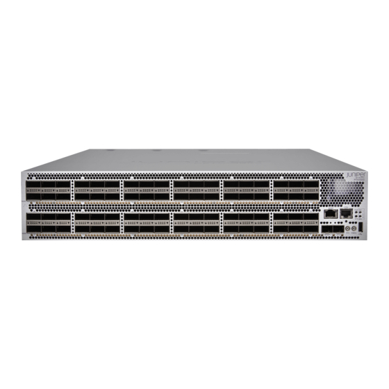
Juniper PTX1000 Hardware Manual
Packet transport router
Hide thumbs
Also See for PTX1000:
- Hardware manual (180 pages) ,
- Quick start manual (8 pages) ,
- Quick start (2 pages)

Subscribe to Our Youtube Channel
Related Manuals for Juniper PTX1000


Summary of Contents for Juniper PTX1000
- Page 1 PTX1000 Packet Transport Router Hardware Guide Modified: 2018-07-03 Copyright © 2018, Juniper Networks, Inc.
- Page 2 END USER LICENSE AGREEMENT The Juniper Networks product that is the subject of this technical documentation consists of (or is intended for use with) Juniper Networks software. Use of such software is subject to the terms and conditions of the End User License Agreement (“EULA”) posted at https://www.juniper.net/support/eula/.
-
Page 3: Table Of Contents
PTX1000 Management Panel ........ - Page 4 PTX1000 Site Preparation Checklist ........
- Page 5 Maintaining Components ......... . 87 Maintaining the PTX1000 Fan Modules ....... . . 87 Removing a Fan Module from the PTX1000 .
- Page 6 PTX1000 Agency Approvals ........
- Page 7 Figure 16: Fan Module LEDs on a PTX1000 ....... 36...
- Page 8 Figure 31: Connecting a Straight DC Power Cable to a DC Power Supply in a PTX1000 (CBL-JNP-PWR-DSUB) ........78 Figure 32: Connecting a Right-Angle DC Power Cable to a DC Power Supply in a PTX1000 (CBL-JNP-PWR-DSUB2) .
- Page 9 Table 10: PTX1000 Chassis Status LEDs ....... . . 33...
- Page 10 PTX1000 Packet Transport Router Hardware Guide Copyright © 2018, Juniper Networks, Inc.
-
Page 11: About The Documentation
® To obtain the most current version of all Juniper Networks technical documentation, see the product documentation page on the Juniper Networks website at https://www.juniper.net/documentation/ If the information in the latest release notes differs from the information in the documentation, follow the product Release Notes. -
Page 12: Table 1: Notice Icons
PTX1000 Packet Transport Router Hardware Guide Table 1: Notice Icons Icon Meaning Description Informational note Indicates important features or instructions. Caution Indicates a situation that might result in loss of data or hardware damage. Warning Alerts you to the risk of personal injury or death. -
Page 13: Documentation Feedback
We encourage you to provide feedback, comments, and suggestions so that we can improve the documentation. You can provide feedback by using either of the following methods: Online feedback rating system—On any page of the Juniper Networks TechLibrary site , simply click the stars to rate the https://www.juniper.net/documentation/index.html content, and use the pop-up form to provide us with information about your experience. -
Page 14: Requesting Technical Support
7 days a week, 365 days a year. Self-Help Online Tools and Resources For quick and easy problem resolution, Juniper Networks has designed an online self-service portal called the Customer Support Center (CSC) that provides you with the following features: Find CSC offerings: https://www.juniper.net/customers/support/... - Page 15 About the Documentation For international or direct-dial options in countries without toll-free numbers, see https://www.juniper.net/support/requesting-support.html Copyright © 2018, Juniper Networks, Inc.
- Page 16 PTX1000 Packet Transport Router Hardware Guide Copyright © 2018, Juniper Networks, Inc.
-
Page 17: Overview
Networks Junos operating system (Junos OS). The Routing Engine handles routing protocols, traffic engineering, policy, policing, monitoring, and configuration management. Junos OS is installed on the PTX1000 router’s internal 2 x 64-gigabyte (GB) M.2 SATA solid-state drives (SSDs). The 64-GB SSDs have 50 GB of usable space—the remaining space is reserved. -
Page 18: Benefits Of The Ptx1000 Router
Forwarding operations are performed by the Packet Forwarding Engines, which include ASICs designed by Juniper Networks. The custom ExpressPlus ASICs enable the PTX1000 to provide up to 2.88 terabits per second (Tbps) of forwarding capacity. The ExpressPlus ASICs are connected to Hybrid Memory Cubes (HMCs). These high-efficiency memory modules provide packet buffering, virtual output queue (VOQ) memory, and improved logical system scale. -
Page 19: Port Panel And Management Panel
Port Panel and Management Panel The port panel of the PTX1000 contains 72 network ports and port LEDs. The management panel of the PTX1000 contains console and management ports, a reset button, system status LEDs, clocking ports, and a USB port. -
Page 20: Fru Panel
In the PTX1000 cooling system, cool air enters through the vents in the port panel and hot air exhausts through the FRU panel. This type of airflow is known as airflow out or port-to-FRU airflow. -
Page 21: Ptx1000 Hardware Component Overview
PTX1000 Component Redundancy The following hardware components provide redundancy on PTX1000 models: Cooling system—The PTX1000 has three fan modules. Each fan module is a redundant unit containing two fans. If a fan module fails and the remaining fan modules are unable to keep the PTX1000 within the desired temperature thresholds, chassis alarms are raised and the PTX1000 might shut down. -
Page 22: Ptx1000 Port Panel
Required Actions Before Removal Power supplies (4) Remove the power cord or cable for the power supply unit. NOTE: You need a minimum of two powered power supplies for the PTX1000 to operate properly. Fan modules (3) None. Optical transceivers None. -
Page 23: Ptx1000 Port Panel
Chapter 1: Overview PTX1000 Port Panel The PTX1000 supports 10-Gbps, 40-Gbps, and 100-Gbps port speeds. Figure 4 on page 23 shows the PTX1000 port panel and management panel. Figure 4: PTX1000 Port Panel and Management Panel 1— Port panel 2—... -
Page 24: Example: Using Network Ports As 40-Gigabit Ethernet Interfaces
PTX1000 Port Mapping on page 25 Example: Using Network Ports as 40-Gigabit Ethernet Interfaces All network ports on the PTX1000 can be configured as 40-Gigabit Ethernet interfaces. You must configure 40-Gigabit Ethernet interfaces in groups of three network ports. When the port speed is configured as 40 Gbps on the first port in a port group, all three ports in the port group operate at 40 Gbps. -
Page 25: Example: Using Network Ports As 100-Gigabit Ethernet Interfaces
After you commit this configuration, port operates at 100 Gbps, while ports are disabled. PTX1000 Port Mapping Table 6 on page 26 shows the available combinations for the network ports on the PTX1000. Copyright © 2018, Juniper Networks, Inc. -
Page 26: Table 6: Ptx1000 Port Mapping
PTX1000 Packet Transport Router Hardware Guide Table 6: PTX1000 Port Mapping 40-Gigabit 4 x 10-Gigabit Ethernet Ports Disabled When a Ethernet Channelized Port 100-Gigabit 100-Gigabit Ethernet Port Number Ports (Default) Groups Ethernet Ports Interface Is Configured – – 0, 2 –... - Page 27 Chapter 1: Overview Table 6: PTX1000 Port Mapping (continued) 40-Gigabit 4 x 10-Gigabit Ethernet Ports Disabled When a Ethernet Channelized Port 100-Gigabit 100-Gigabit Ethernet Port Number Ports (Default) Groups Ethernet Ports Interface Is Configured – – – – 21, 22 –...
- Page 28 PTX1000 Packet Transport Router Hardware Guide Table 6: PTX1000 Port Mapping (continued) 40-Gigabit 4 x 10-Gigabit Ethernet Ports Disabled When a Ethernet Channelized Port 100-Gigabit 100-Gigabit Ethernet Port Number Ports (Default) Groups Ethernet Ports Interface Is Configured – – 42, 44 –...
-
Page 29: Ptx1000 Network Port Leds
69, 70 PTX1000 Network Port LEDs Each PTX1000 network port uses a single bicolored LED to indicate link status and activity. The triangular LEDs are located between the top row and bottom row of ports. The LEDs are shaped so that each LED points to the port with which it is associated. -
Page 30: Ptx1000 Management Panel
2— Management panel You manage the PTX1000 by using the Junos OS CLI, which is accessible through the console and out-of-band management ports on the management panel. In addition, the management panel has system status LEDs that alert you to minor or major alarms or other issues with the router, external clock synchronization ports, and a USB port to support software installation and recovery. -
Page 31: Ptx1000 Management Port Leds
). In the Junos OS CLI, this port is identified as PTX1000 Management Port LEDs There are two management ports on the PTX1000, located on the management panel next to the network ports. Both ports are labeled MGMT . The RJ-45 management port is for 10/100/1000BASE-T connections and the small form-factor pluggable (SFP) management port is for 10/100/1000BASE-T and 1000BASE-X connections. -
Page 32: Ptx1000 Chassis Status Leds
Blinking or flickering A link is established, and there is link activity. PTX1000 Chassis Status LEDs The PTX1000 has four status LEDs on the management panel of the chassis, next to the network ports (see Figure 12 on page 33). -
Page 33: Figure 12: Chassis Status Leds On A Ptx1000
) position or by unplugging the AC power cords. Correct any voltage issues. Power on the PTX1000 and monitor the power supply and fan LEDs to help determine where the error is occurring. If there is a CPU power failure, the PTX1000 does not boot. -
Page 34: Ptx1000 Cooling System
Airflow Through the Chassis on page 35 Fan Modules The cooling system in a PTX1000 consists of three 80-W fan modules that operate at 150 cubic feet per minute (CFM) at full speed as well as fans housed in the power supplies. -
Page 35: Airflow Through The Chassis
Airflow Through the Chassis In the PTX1000 cooling system, cool air enters through the vents in the port panel and hot air exhausts through the FRU panel. This type of airflow is known as airflow out or port-to-FRU airflow. When the chassis is installed, it must be positioned so that the FRUs are next to the hot aisle. -
Page 36: Ptx1000 Power System
Figure 17 on page 37 Figure 18 on page are hot-removable, and hot-insertable field-replaceable units (FRUs) that you can install without powering off the router or disrupting the routing function. The PTX1000 has four power supplies. CAUTION: Do not mix AC and DC power supplies in the same chassis. -
Page 37: Figure 17: Ptx1000 Fru Panel
Each of the 1600-W power supplies has a single AC input. The power supply provides 12-VDC output with a standby voltage of 12 VDC. A PTX1000 provides for twice the number of power supplies needed to power all of the components in the device, which is known as 2N redundancy. -
Page 38: Ptx1000 Dc Power Supply Description
Each of the four 1600-W power supplies has a single DC input. The power supply provides 12-VDC output with a standby voltage of 12 VDC. A PTX1000 provides for twice the number of power supplies needed to power all of the components in the router, which is known as 2N redundancy. -
Page 39: Ptx1000 Power Supply Leds
“PTX1000 Component Redundancy” on page PTX1000 Power Supply LEDs Each PTX1000 power supply has a status LED on the power supply faceplate. Figure 21 on page 39 shows the location of the LED on a PTX1000 AC power supply and Figure 22 on page 39 shows the location of the LED on a PTX1000 DC power supply. -
Page 40: Ptx1000 Ac Power Specifications
Check the fan modules and the fans in the power supplies and ensure there is proper airflow through the chassis. PTX1000 AC Power Specifications Table 13 on page 40 describes the AC power specifications for a PTX1000. Table 13: PTX1000 AC Power Specifications Item Specifications AC input voltage Operating range: 100–240 VAC... -
Page 41: Ptx1000 Dc Power Specifications
(approximately 4.5 meters) in length, to comply with National Electrical Code (NEC) Sections 400-8 (NFPA 75, 5-2.2) and 210-52 and Canadian Electrical Code (CEC) Section 4-010(3). The cords that can be ordered for the PTX1000 are in compliance. Table 14 on page 41 lists AC power cord specifications provided for each country or region. -
Page 42: Ptx1000 Dc Power Cable Specifications
“Connecting the PTX1000 to Ground” on page DC power cables, each approximately 13.1 ft (4 m) long, are supplied with the PTX1000. The provided cables include the three-pin connector on one end and insulated wires at the opposite end, for connection to the site’s DC power distribution system. - Page 43 Chapter 1: Overview WARNING: For field-wiring connections, use copper conductors only. WARNING: Power cables must not block access to PTX1000 components or drape where people could trip over them. CAUTION: You must ensure that power connections maintain the proper polarity. The power source cables might be labeled to indicate (–)
- Page 44 PTX1000 Packet Transport Router Hardware Guide Copyright © 2018, Juniper Networks, Inc.
-
Page 45: Site Planning, Preparation, And Specifications
Specifications PTX1000 Site Preparation Checklist on page 45 PTX1000 Site Guidelines and Requirements on page 46 PTX1000 Network Cable and Transceiver Planning on page 52 PTX1000 Management Cable Specifications and Pinouts on page 62 PTX1000 Site Preparation Checklist The checklist in... -
Page 46: Ptx1000 Site Guidelines And Requirements
Site Electrical Wiring Guidelines on page 50 PTX1000 Rack Requirements on page 51 PTX1000 Environmental Requirements and Specifications The PTX1000 must be installed in a rack. It must be housed in a dry, clean, well-ventilated, and temperature-controlled environment. Copyright © 2018, Juniper Networks, Inc. -
Page 47: Site Planning, Preparation, And Specifications
The site must be as dust-free as possible, because dust can clog air intake vents and filters, reducing the efficiency of the PTX1000 cooling system. Maintain ambient airflow for normal PTX1000 operation. If the airflow is blocked or restricted, or if the intake air is too warm, the chassis might overheat, leading to the PTX1000 temperature monitor shutting down the router to protect the hardware components. -
Page 48: General Site Guidelines
(EMI) requirements. To ground a PTX1000, connect a grounding cable to earth ground and then attach it to the chassis grounding points. -
Page 49: Ptx1000 Clearance Requirements For Airflow And Hardware Maintenance
The grounding lug required is a Panduit LCD6-14BH-L or equivalent (not provided). The grounding lug accommodates 14–6 AWG (2–13.3 mm²) stranded wire. The grounding cable that you provide for a PTX1000 must be the same size or heavier than the input wire of each power supply. Minimum recommendations are 8 AWG (8.4 mm²) stranded wire, 60°... -
Page 50: Ptx1000 Physical Specifications
PTX1000 Packet Transport Router Hardware Guide You must leave at least 24 in. (61 cm) both in front of and behind the PTX1000 for service personnel to remove and install hardware components, you must leave adequate space at the front and back of the PTX1000. NEBS GR-63 recommends that you allow at least 30 in. -
Page 51: Ptx1000 Rack Requirements
EIA-310–D) published by the Electronics Components Industry Association http://www.ecianow.org/ Mounting bracket hole The holes in the mounting brackets are spaced at 1 U (1.75 in. or 4.45 cm), so that the PTX1000 can spacing be mounted in any rack that provides holes spaced at that distance. -
Page 52: Ptx1000 Network Cable And Transceiver Planning
Ensure that the front and rear rack rails are spaced between 28 in. (71.1 cm) and 36 in. (91.4 cm) front-to-back. Ensure that the rack is strong enough to support the weight of the PTX1000. Ensure that the spacing of rails and adjacent racks allows for proper clearance around the PTX1000 and rack. Rack connection to Secure the rack to the building structure. -
Page 53: Devices
The Hardware Compatibility Tool enables you to search by product, displaying all the transceivers supported on that device, or category, by interface speed or type. The list of supported transceivers for the PTX1000 is located at https://pathfinder.juniper.net/hct/product/#prd=PTX1000... -
Page 54: 12-Fiber Mpo Connectors
LC Duplex Connectors on page 58 12-Fiber MPO Connectors There are two types of cables used with 12-fiber MPO connectors on Juniper Networks devices—patch cables with MPO connectors on both ends, and breakout cables with an MPO connector on one end and four LC duplex connectors on the opposite end. Depending on the application, the cables might use single-mode fiber (SMF) or multimode fiber (MMF). -
Page 55: Table 23: Cable Pinouts For 12-Fiber Ribbon Patch Cables
Table 22: Cable Signals for 12-Fiber Ribbon Patch Cables (continued) Fiber Signal Unused Unused Unused Rx3 (Receive) Rx2 (Receive) Rx1 (Receive) Rx0 (Receive) Table 23: Cable Pinouts for 12-Fiber Ribbon Patch Cables MPO Pin MPO Pin Copyright © 2018, Juniper Networks, Inc. -
Page 56: Table 24: Cable Pinouts For 12-Fiber Ribbon Breakout Cables
12-Ribbon Patch and Breakout Cables Available from Juniper Networks Juniper Networks sells 12-ribbon patch and breakout cables with MPO connectors that meet the requirements described above. It is not required to purchase cables from Juniper Networks. Table 25 on page 57 describes the available cables. -
Page 57: 24-Fiber Mpo Connectors
Chapter 2: Site Planning, Preparation, and Specifications Table 25: 12-Ribbon Patch and Breakout Cables Available from Juniper Networks Cable Fiber Type Connector Type Type Cable Length Juniper Model Number 12-ribbon Female MPO/PC to MTP12-FF-M1M patch female MPO/PC, key (OM3) up to key up... -
Page 58: Lc Duplex Connectors
PTX1000 Packet Transport Router Hardware Guide Figure 24: 24-Fiber MPO Optical Lane Assignments NOTE: Ensure that you order cables with the correct polarity. Vendors refer to these crossover cables as key up to key up, latch up to latch up, Type B, or Method B. -
Page 59: Dispersion
Although attenuation is significantly lower for optical fiber than for other media, it still occurs in both multimode and single-mode transmission. An efficient optical data link must have enough light available to overcome attenuation. Copyright © 2018, Juniper Networks, Inc. -
Page 60: Calculating Power Budget And Power Margin For Fiber-Optic Cables
You can use the to find information about Hardware Compatibility Tool the pluggable transceivers supported on your Juniper Networks device. To calculate the power budget and power margin, perform the following tasks: Calculating Power Budget for Fiber-Optic Cable on page 60... -
Page 61: Calculating Power Margin For Fiber-Optic Cable
(0.5 dB). The power margin (P ) is calculated as follows: – LL = 13 dB – 2 km (1 dB/km) – 5 (0.5 dB) – 2 (0.5 dB) – 0.5 dB Copyright © 2018, Juniper Networks, Inc. -
Page 62: Ptx1000 Management Cable Specifications And Pinouts
See “Determining Transceiver Support for the PTX1000” on page 52 for more information about supported transceivers. Table 27: Cable Specifications for Console and Management Connections for the PTX1000 Device Port on PTX1000 Cable Specification Cable Supplied... -
Page 63: Management Port Connector Pinouts For The Ptx1000
Table 29 on page 64 provides the pinout information for the RJ-45 console connector. An RJ-45 cable and an RJ-45 to DB-9 adapter are supplied with the PTX1000. NOTE: If your laptop or PC does not have a DB-9 male connector pin and you... -
Page 64: Usb Port Specifications For The Ptx1000
CTS Input Clear to send USB Port Specifications for the PTX1000 USB flash drives used with the PTX1000 must support USB 2.0 or later. CAUTION: Remove the USB flash drive before upgrading Junos OS or rebooting a PTX1000. Failure to do so could expose your router to unpredictable behavior. -
Page 65: Initial Installation And Configuration
PTX1000 Installation Safety Guidelines on page 66 Overview of Installing the PTX1000 You can mount a PTX1000 flush with the front of a 19-in. four-post rack. Use the standard mounting brackets provided with the PTX1000 for this configuration. Before you begin to install and connect a PTX1000, ensure that you have reviewed the information in “PTX1000 Installation Safety Guidelines”... -
Page 66: Ptx1000 Installation Safety Guidelines
41 PTX1000 Chassis Lifting Guidelines The weight of a fully-loaded PTX1000 is approximately 68.6 lb (31.1 kg) with AC power supplies and 67.8 lb (30.8 kg) with DC power supplies installed. In addition to the guidelines described in “Chassis and Component Lifting Guidelines”... -
Page 67: Unpacking And Mounting The Ptx1000
Remove the accessory kit and verify the contents against the inventory of components listed in Table 30 on page Pull out the packing material holding the PTX1000 in place and the PTX1000 chassis. Verify the chassis components received: Three fan modules... -
Page 68: Mounting The Ptx1000 In A Rack
RJ-45 cable and RJ-45 to DB-9 adapter Mounting the PTX1000 in a Rack You can mount a PTX1000 in a four post 19-in. rack by using the included mounting brackets. For four-post rack installation, the shipping carton contains two front-mounting rails with two matching rear-mounting blades. -
Page 69: Mounting The Ptx1000
Decide whether the field-replaceable unit (FRU) end or the port end of the PTX1000 must be placed at the front of the rack. Position the PTX1000 in such a manner that labels on components are next to the hot aisle. -
Page 70: Figure 26: Removing The Screws Holding The Cover On The Ptx1000
PTX1000. Perform one of the following steps: Use a mechanical lift to position the PTX1000 in the rack so that the ears on the front-mounting rails are aligned with the rack holes. Have two persons grasp both sides of the PTX1000, lift it, and position it in the rack so that the ears on the front-mounting rails are aligned with the rack holes. -
Page 71: Connecting The Ptx1000 To Power
Chapter 3: Initial Installation and Configuration Figure 28: Attaching Rear-Mounting Blades to the Rack Ensure that the PTX1000 chassis is level by verifying that all the screws on the front of the rack are aligned with the screws at the back of the rack. -
Page 72: Connecting The Ptx1000 To Ground
For installations that require a separate grounding conductor to the chassis, use the protective earthing terminal on the PTX1000 chassis to connect to the earth ground. NOTE:... -
Page 73: Connecting Ac Power To The Ptx1000
(ESD) damage (see “Prevention of Electrostatic Discharge Damage” on page 135). Ensure that you have connected the PTX1000 chassis to earth ground. CAUTION: Before you connect power to the PTX1000, a licensed electrician must attach a cable lug to the grounding and power cables that you supply. - Page 74 Ensure that the power supplies are fully inserted in the chassis and the latches are secure. Locate the power cord or cords shipped with the PTX1000; the cords have plugs appropriate for your geographical location. See “PTX1000 AC Power Cord Specifications”...
-
Page 75: Figure 30: Connecting An Ac Power Cord To An Ac Power Supply In A
(see Figure 30 on page 75). Figure 30: Connecting an AC Power Cord to an AC Power Supply in a PTX1000 If the AC power source outlet has a power switch, set it to the off ( ) position. -
Page 76: Connecting Dc Power To The Ptx1000
For installations that require a separate grounding conductor to the chassis, use the protective earthing terminal on the PTX1000 chassis to connect to the earth ground (see “Connecting the PTX1000 to Ground” on page 72). - Page 77 10 lb-in (1.13 Nm). Power cable or cables appropriate for your geographical location available to connect DC power to the PTX1000. There are two types of DC power cables—a straight DC power cable (CBL-JNP-PWR-DSUB) and a right-angle DC power cable (CBL-JNP-PWR-DSUB2 or CBL-JNP-PWR-DSUB3).
-
Page 78: Figure 31: Connecting A Straight Dc Power Cable To A Dc Power Supply In A Ptx1000 (Cbl-Jnp-Pwr-Dsub)
PTX1000 Packet Transport Router Hardware Guide Figure 31: Connecting a Straight DC Power Cable to a DC Power Supply in a PTX1000 (CBL-JNP-PWR-DSUB) Figure 32: Connecting a Right-Angle DC Power Cable to a DC Power Supply in a PTX1000 (CBL-JNP-PWR-DSUB2) -
Page 79: Figure 33: Connecting A Right-Angle Dc Power Cable To A Dc Power Supply In A Ptx1000 (Cbl-Jnp-Pwr-Dsub3)
Chapter 3: Initial Installation and Configuration Figure 33: Connecting a Right-Angle DC Power Cable to a DC Power Supply in a PTX1000 (CBL-JNP-PWR-DSUB3) WARNING: Ensure that the power cables do not block access to device components or drape where people could trip over them. -
Page 80: Connecting The Ptx1000 To External Devices
PTX1000 Packet Transport Router Hardware Guide NOTE: The PTX1000 powers on as soon as power is provided to the power supply. There is no power switch on the router. Verify that the status LEDs on each power supply are lit green. -
Page 81: Connecting The Ptx1000 To A Management Console
Figure 34: Connecting a PTX1000 to a Network for Out-of-Band Management Connecting the PTX1000 to a Management Console The PTX1000 has a console port with an RJ-45 connector. Use the console port to connect the router directly to a management console, such as a laptop, or to a console server. -
Page 82: Performing The Initial Software Configuration For The Ptx1000
Documentation Performing the Initial Software Configuration for the PTX1000 You must perform the initial configuration of the PTX1000 through the console port by using the Junos OS command-line interface (CLI). Before you begin connecting and configuring a PTX1000, set the following parameter values on the management console or console server: Baud Rate—9600... - Page 83 [edit] root@# set system root-authentication plain-text-password New password: password Retype new password: password (Optional) Configure the name of the PTX1000. If the name includes spaces, enclose the name in quotation marks (“ ”). [edit] root@# set system host-name host-name Configure the default gateway.
-
Page 84: Powering Off The Ptx1000
135. Ensure that you do not need to route traffic through the PTX1000. Ensure that you have the following parts and tools available to power off the PTX1000: An ESD grounding strap An external management device such as a PC... - Page 85 Please press any key to reboot. CAUTION: Although traffic and the operating system have stopped, the PTX1000 PSM LEDs remain lit and a fan module continues to run. Wait at least 60 seconds after first seeing this message before following the instructions in Step and Step to power off the PTX1000.
- Page 86 PTX1000 Packet Transport Router Hardware Guide Copyright © 2018, Juniper Networks, Inc.
-
Page 87: Maintaining Components
Before removing the fan module, ensure you have a replacement fan module available. Before you remove a fan module from a PTX1000, ensure that you have taken the necessary precautions to prevent electrostatic discharge (ESD) damage (see “Prevention of Electrostatic Discharge Damage”... -
Page 88: Installing A Fan Module In The Ptx1000
Installing a Fan Module in the PTX1000 The fan modules in a PTX1000 are hot-removable and hot-insertable field-replaceable units (FRUs)—you can remove and replace them without powering off the PTX1000 or disrupting routing functions. Copyright © 2018, Juniper Networks, Inc. -
Page 89: Figure 38: Installing A Fan Module In A Ptx1000
ESD points on the chassis. Taking care not to touch the connectors, remove the fan module from its bag. Align the module with the open slot on the FRU end of the PTX1000 and slide it in until it is fully seated. -
Page 90: Maintaining The Ptx1000 Power Supplies
Before removing the power supply, ensure you have a replacement power supply available. Before you remove a power supply from a PTX1000, ensure that you have taken the necessary precautions to prevent electrostatic discharge (ESD) damage (see “Prevention of Electrostatic Discharge Damage”... -
Page 91: Installing A Power Supply In A Ptx1000
Installing a Power Supply in a PTX1000 The power supplies in a PTX1000 are hot-removable and hot-insertable field-replaceable units (FRUs)—you can remove and replace them without powering off the PTX1000 or disrupting routing functions. CAUTION: Replace the power supply within 30 seconds of removal to prevent chassis overheating. -
Page 92: Figure 40: Installing A Power Supply In A Ptx1000
Using both hands, place the power supply in the power supply slot on the FRU panel of the PTX1000 and slide it in until it is fully seated and the locking lever slides into place. -
Page 93: Maintaining The Ptx1000 Transceivers And Fiber-Optic Cables
(FRUs)—you can remove and replace them without powering off the PTX1000 or disrupting routing functions. Before you begin removing a transceiver from a PTX1000, ensure that you have taken the necessary precautions for safe handling of lasers (see “Radiation from Open Port Apertures Warning”... - Page 94 PTX1000 Packet Transport Router Hardware Guide WARNING: Do not leave a fiber-optic transceiver uncovered except when inserting or removing a cable. The rubber safety cap keeps the port clean and prevents accidental exposure to laser light. CAUTION: Do not bend fiber-optic cables beyond their minimum bend radius.
-
Page 95: Installing A Transceiver In The Ptx1000
(FRUs)—you can remove and replace them without powering off the PTX1000 or disrupting routing functions. Before you begin installing a transceiver in a PTX1000, ensure that you have taken the necessary precautions for safe handling of lasers (see “Radiation from Open Port Apertures Warning”... -
Page 96: Disconnecting A Fiber-Optic Cable From The Ptx1000
Disconnecting a Fiber-Optic Cable from the PTX1000 The PTX1000 has optical transceivers to which you can connect fiber-optic cables. Before you disconnect a fiber-optic cable from a PTX1000, ensure that you have taken the necessary precautions for safe handling of lasers (see “Radiation from Open Port... -
Page 97: Connecting A Fiber-Optic Cable To The Ptx1000
Connecting a Fiber-Optic Cable to the PTX1000 The PTX1000 has optical transceivers to which you can connect fiber-optic cables. Before you connect a fiber-optic cable to a PTX1000, ensure that you have taken the necessary precautions for safe handling of lasers (see “Radiation from Open Port... -
Page 98: Maintaining Fiber-Optic Cables In A Ptx1000
PTX1000 Packet Transport Router Hardware Guide To connect a fiber-optic cable to an optical transceiver installed in the PTX1000: WARNING: Do not look directly into a fiber-optic transceiver or into the ends of fiber-optic cables. Fiber-optic transceivers and fiber-optic cables connected to transceivers emit laser light that can damage your eyes. -
Page 99: Uninstalling The Ptx1000
Before removing a PTX1000 from a rack: Ensure that the rack is stable and secured to the building. Ensure that there is enough space to place the removed PTX1000 in its new location and along the path to the new location. - Page 100 To remove a PTX1000 from a rack: Perform one of the following steps: Position a mechanical lift under the PTX1000. Use the screwdriver to remove the front-mounting screws that attach the router to the rack. Have two persons support the weight of the PTX1000 while another person uses the screwdriver to remove the front-mounting screws that attach the router to the rack.
-
Page 101: Troubleshooting Hardware
Chassis Alarm Messages on the PTX1000 on page 102 PTX1000 Troubleshooting Resources Overview To troubleshoot a PTX1000, you use the Junos OS CLI, alarms, and LEDs on the network ports, management panel, and components. LEDs—When the Routing Engine detects an alarm condition, it lights the red or yellow alarm LED on the management panel as appropriate. -
Page 102: Ptx1000 Alarm Messages Overview
Chassis alarms indicate a failure on the device or one of its components. Chassis alarms are preset and cannot be modified. Chassis alarms on PTX1000 routers have two severity levels: Major (red)—Indicates a critical situation on the device that has resulted from one of... -
Page 103: Troubleshooting Hardware
Chapter 5: Troubleshooting Hardware Table 31: PTX1000 Chassis Alarm Messages (continued) Component Alarm Type CLI Message Recommended Action Power supplies Major (red) Replace the power supply with a power PEM pem-number Airflow not matching supply that supports the same airflow Chassis Airflow direction as the chassis. - Page 104 PTX1000 Packet Transport Router Hardware Guide Table 31: PTX1000 Chassis Alarm Messages (continued) Component Alarm Type CLI Message Recommended Action Temperature Major (red) Check the system log for the following sensor-location Temp Sensor Fail sensors message and report it to customer...
-
Page 105: Returning The Chassis Or Components
Packing a PTX1000 Chassis or Component for Shipping on page 107 Locating the Serial Number on a PTX1000 Chassis or Component If you are returning a PTX1000 or a PTX1000 field-replaceable unit (FRU) to Juniper Networks for repair or replacement, you must locate the serial number of the router or FRU. -
Page 106: Listing The Chassis And Component Details By Using The Cli
Fan module—The serial number ID label is on the top of the fan module. Contacting Customer Support to Obtain Return Material Authorization If you are returning a device or hardware component to Juniper Networks for repair or replacement, obtain a Return Material Authorization (RMA) number from Juniper Networks Technical Assistance Center (JTAC). -
Page 107: Packing A Ptx1000 Chassis Or Component For Shipping
Prevention of Electrostatic Discharge Damage on page 135 Packing a PTX1000 Chassis or Component for Shipping If you are returning a PTX1000 or component to Juniper Networks for repair or replacement, pack the item as described in this topic. Before you pack a PTX1000 or component: Ensure that you have taken the necessary precautions to prevent electrostatic discharge (ESD) damage. -
Page 108: Packing A Ptx1000 For Shipping
Packing a PTX1000 for Shipping To pack a PTX1000 for shipping: Power off the PTX1000 and remove the AC power cords or DC power cables. See “Powering Off the PTX1000” on page Remove the cables that connect the PTX1000 to all external devices. See “Disconnecting a Fiber-Optic Cable from the PTX1000”... - Page 109 Chapter 6: Returning the Chassis or Components To pack and ship PTX1000 components: Place individual FRUs in antistatic bags. Ensure that the components are adequately protected with packing materials and packed so that the pieces are prevented from moving around inside the carton.
- Page 110 PTX1000 Packet Transport Router Hardware Guide Copyright © 2018, Juniper Networks, Inc.
-
Page 111: Safety And Compliance Information
Prevention of Electrostatic Discharge Damage on page 135 AC Power Electrical Safety Guidelines on page 136 AC Power Disconnection Warning on page 137 PTX1000 DC Power Electrical Safety Guidelines on page 138 DC Power Copper Conductors Warning on page 139 DC Power Disconnection Warning on page 139... -
Page 112: General Safety Guidelines And Warnings
PTX1000 Packet Transport Router Hardware Guide General Safety Guidelines and Warnings The following guidelines help ensure your safety and protect the device from damage. The list of guidelines might not address all potentially hazardous situations in your working environment, so be alert and exercise good judgment at all times. -
Page 113: Definitions Of Safety Warning Levels
Varoitus Tämä varoitusmerkki merkitsee vaaraa. Olet tilanteessa, joka voi johtaa ruumiinvammaan. Ennen kuin työskentelet minkään laitteiston parissa, Copyright © 2018, Juniper Networks, Inc. - Page 114 PTX1000 Packet Transport Router Hardware Guide ota selvää sähkökytkentöihin liittyvistä vaaroista ja tavanomaisista onnettomuuksien ehkäisykeinoista. Attention Ce symbole d'avertissement indique un danger. Vous vous trouvez dans une situation pouvant causer des blessures ou des dommages corporels. Avant de travailler sur un équipement, soyez conscient des dangers posés par les circuits électriques et familiarisez-vous avec les procédures...
-
Page 115: Qualified Personnel Warning
AC Power Electrical Safety Guidelines on page 136 PTX5000 AC Power Electrical Safety Guidelines PTX5000 AC Power Electrical Safety Warnings DC Power Electrical Safety Guidelines PTX1000 DC Power Electrical Safety Guidelines on page 138 Copyright © 2018, Juniper Networks, Inc. -
Page 116: Warning Statement For Norway And Sweden
In addition, you should establish procedures to protect your equipment in the event of a fire emergency. Juniper Networks products should be installed in an environment suitable for electronic equipment. We recommend that fire suppression equipment be available in the event of a fire in the vicinity of the equipment and that all local fire, safety, and electrical codes and ordinances be observed when you install and operate your equipment. -
Page 117: Installation Instructions Warning
To keep warranties effective, do not use a dry chemical fire extinguisher to control a fire at or near a Juniper Networks device. If a dry chemical fire extinguisher is used, the unit is no longer eligible for coverage under a service agreement. -
Page 118: Chassis And Component Lifting Guidelines
PTX1000 Packet Transport Router Hardware Guide Related General Safety Guidelines and Warnings on page 112 Documentation Laser and LED Safety Guidelines and Warnings on page 126 Laser and LED Safety Guidelines and Warnings for the ACX5000 Router Grounded Equipment Warning on page 124... - Page 119 Related General Safety Guidelines and Warnings on page 112 Documentation General Electrical Safety Guidelines and Warnings on page 133 Installation Instructions Warning on page 117 Copyright © 2018, Juniper Networks, Inc.
-
Page 120: Ramp Warning
PTX1000 Packet Transport Router Hardware Guide Grounded Equipment Warning on page 124 Ramp Warning WARNING: When installing the device, do not use a ramp inclined at more than 10 degrees. Waarschuwing Gebruik een oprijplaat niet onder een hoek van meer dan 10 graden. - Page 121 Les directives ci-dessous sont destinées à assurer la protection du personnel: Le rack sur lequel est monté le Juniper Networks switch doit être fixé à la structure du bâtiment. Si cette unité constitue la seule unité montée en casier, elle doit être placée dans le bas.
- Page 122 Le seguenti direttive vengono fornite per garantire la sicurezza personale: Il Juniper Networks switch deve essere installato in un telaio, il quale deve essere fissato alla struttura dell'edificio. Questa unità deve venire montata sul fondo del supporto, se si tratta dell'unica unità...
- Page 123 Para garantizar su seguridad, proceda según las siguientes instrucciones: El Juniper Networks switch debe instalarse en un bastidor fijado a la estructura del edificio. Colocar el equipo en la parte inferior del bastidor, cuando sea la única unidad en el mismo.
-
Page 124: Grounded Equipment Warning
PTX1000 Packet Transport Router Hardware Guide Juniper Networks switch måste installeras i en ställning som är förankrad i byggnadens struktur. Om denna enhet är den enda enheten på ställningen skall den installeras längst ned på ställningen. Om denna enhet installeras på en delvis fylld ställning skall ställningen fyllas nedifrån och upp, med de tyngsta enheterna längst ned på... -
Page 125: Radiation From Open Port Apertures Warning
Varning! Osynlig strålning kan avges från en portöppning utan ansluten fiberkabel och du bör därför undvika att bli utsatt för strålning genom att inte stirra in i oskyddade öppningar. Copyright © 2018, Juniper Networks, Inc. -
Page 126: Laser And Led Safety Guidelines And Warnings
Grounded Equipment Warning on page 124 Laser and LED Safety Guidelines and Warnings Juniper Networks devices are equipped with laser transmitters, which are considered a Class 1 Laser Product by the U.S. Food and Drug Administration and are evaluated as a Class 1 Laser Product per EN 60825-1 requirements. -
Page 127: Class 1 Led Product Warning
Varoitus Älä katso säteeseen äläkä tarkastele sitä suoraan optisen laitteen avulla. Attention Ne pas fixer le faisceau des yeux, ni l'observer directement à l'aide d'instruments optiques. Warnung Nicht direkt in den Strahl blicken und ihn nicht direkt mit optischen Geräten prüfen. Copyright © 2018, Juniper Networks, Inc. -
Page 128: Maintenance And Operational Safety Guidelines And Warnings
PTX1000 Packet Transport Router Hardware Guide Avvertenza Non fissare il raggio con gli occhi né usare strumenti ottici per osservarlo direttamente. Advarsel Stirr eller se ikke direkte p strlen med optiske instrumenter. Aviso Não olhe fixamente para o raio, nem olhe para ele directamente com instrumentos ópticos. -
Page 129: Jewelry Removal Warning
(inclusief ringen, kettingen en horloges) verwijderen. Metalen voorwerpen worden warm wanneer ze met stroom en aarde zijn verbonden, en kunnen ernstige brandwonden veroorzaken of het metalen voorwerp aan de aansluitklemmen lassen. Copyright © 2018, Juniper Networks, Inc. - Page 130 PTX1000 Packet Transport Router Hardware Guide Varoitus Ennen kuin työskentelet voimavirtajohtoihin kytkettyjen laitteiden parissa, ota pois kaikki korut (sormukset, kaulakorut ja kellot mukaan lukien). Metalliesineet kuumenevat, kun ne ovat yhteydessä sähkövirran ja maan kanssa, ja ne voivat aiheuttaa vakavia palovammoja tai hitsata metalliesineet kiinni liitäntänapoihin.
-
Page 131: Lightning Activity Warning
6 in. (15.2 cm) of clearance around the ventilation openings. Waarschuwing Om te voorkomen dat welke switch van de Juniper Networks router dan ook oververhit raakt, dient u deze niet te bedienen op een plaats waar de maximale aanbevolen omgevingstemperatuur van 40°... -
Page 132: Product Disposal Warning
PTX1000 Packet Transport Router Hardware Guide Attention Pour éviter toute surchauffe des routeurs de la gamme Juniper Networks switch, ne l'utilisez pas dans une zone où la température ambiante est supérieure à 40° C. Pour permettre un flot d'air constant, dégagez un espace d'au moins 15,2 cm autour des ouvertures de ventilations. -
Page 133: General Electrical Safety Guidelines And Warnings
The intrabuilding ports on the device are suitable for connection to intrabuilding or unexposed wiring or cabling only. The addition of primary protectors is not sufficient protection for connecting these interfaces metallically to OSP wiring. Copyright © 2018, Juniper Networks, Inc. - Page 134 PTX1000 Packet Transport Router Hardware Guide CAUTION: Before removing or installing components of a device, connect an electrostatic discharge (ESD) grounding strap to an ESD point and wrap and fasten the other end of the strap around your bare wrist. Failure to use an ESD grounding strap could result in damage to the device.
-
Page 135: Action To Take After An Electrical Accident
ESD wrist strap is attached to the ESD point on the chassis. If no grounding strap is available, touch the exposed, bare metal of the device to ground yourself before handling the component. Copyright © 2018, Juniper Networks, Inc. -
Page 136: Ac Power Electrical Safety Guidelines
PTX1000 Packet Transport Router Hardware Guide Avoid contact between the component that is subject to ESD damage and your clothing. ESD voltages emitted from clothing can damage components. When removing or installing a component that is subject to ESD damage, always place... -
Page 137: Ac Power Disconnection Warning
General Electrical Safety Guidelines and Warnings on page 133 Multiple Power Supplies Disconnection Warning on page 145 AC Power Disconnection Warning WARNING: Before working on the device or near power supplies, unplug all the power cords from an AC-powered device. Copyright © 2018, Juniper Networks, Inc. -
Page 138: Ptx1000 Dc Power Electrical Safety Guidelines
PTX1000 DC Power Electrical Safety Guidelines The following electrical safety guidelines apply to a DC-powered PTX1000: A DC-powered PTX1000 is equipped with a DC terminal block that is rated for the power requirements of a maximally configured PTX1000. To supply sufficient power, terminate the DC input wiring on a facility DC source capable of supplying at least 40 A @ –48 VDC per input for the DC power supply. -
Page 139: Dc Power Copper Conductors Warning
Run two wires from the circuit breaker box to a source of 48 VDC. A DC-powered PTX1000 is intended only for installation in a restricted-access location. In the United States, a restricted-access area is one in accordance with Articles 110-16, 110-17, and 110-18 of the National Electrical Code ANSI/NFPA 70. - Page 140 PTX1000 Packet Transport Router Hardware Guide de stroomverbreker naar de UIT positie en plakt de schakelaarhendel van de stroomverbreker met plakband in de UIT positie vast. Varoitus Varmista, että tasavirtapiirissä ei ole virtaa ennen seuraavien toimenpiteiden suorittamista. Varmistaaksesi, että virta on KATKAISTU täysin, paikanna tasavirrasta huolehtivassa kojetaulussa sijaitseva suojakytkin,...
-
Page 141: Dc Power Grounding Requirements And Warning
Aviso Ao instalar a unidade, a ligação à terra deverá ser sempre a primeira a ser ligada, e a última a ser desligada. ¡Atención! Al instalar el equipo, conectar la tierra la primera y desconectarla la última. Copyright © 2018, Juniper Networks, Inc. -
Page 142: Dc Power Wiring Sequence Warning
PTX1000 Packet Transport Router Hardware Guide Varning! Vid installation av enheten måste jordledningen alltid anslutas först och kopplas bort sist. Related General Safety Guidelines and Warnings on page 112 Documentation General Electrical Safety Guidelines and Warnings on page 133 DC Power Electrical Safety Guidelines... -
Page 143: Dc Power Wiring Terminations Warning
DC Power Grounding Requirements and Warning on page 141 DC Power Wiring Terminations Warning on page 143 DC Power Wiring Terminations Warning WARNING: When stranded wiring is required, use approved wiring terminations, such as closed-loop or spade-type with upturned lugs. These Copyright © 2018, Juniper Networks, Inc. - Page 144 PTX1000 Packet Transport Router Hardware Guide terminations must be the appropriate size for the wires and must clamp both the insulation and conductor. Waarschuwing Wanneer geslagen bedrading vereist is, dient u bedrading te gebruiken die voorzien is van goedgekeurde aansluitingspunten, zoals het gesloten-lus type of het grijperschop type waarbij de aansluitpunten omhoog wijzen.
-
Page 145: Multiple Power Supplies Disconnection Warning
å eliminere strøm fra enheten. Aviso Este dispositivo possui mais do que uma conexão de fonte de alimentação de energia; para poder remover a fonte de alimentação de energia, deverão ser desconectadas todas as conexões existentes. Copyright © 2018, Juniper Networks, Inc. -
Page 146: Tn Power Warning
PTX1000 Packet Transport Router Hardware Guide ¡Atención! Esta unidad tiene más de una conexión de suministros de alimentación; para eliminar la alimentación por completo, deben desconectarse completamente todas las conexiones. Varning! Denna enhet har mer än en strömförsörjningsanslutning; alla anslutningar måste vara helt avlägsnade innan strömtillförseln till enheten är fullständigt bruten. -
Page 147: Ptx1000 Agency Approvals And Compliance Statements
EN-61000-4-5 Surge EN-61000-4-6 Low Frequency Common Immunity ETSI EN-300386-2 Telecommunication Network Equipment. Electromagnetic Compatibility Requirements The PTX1000 is designed to comply with the following standard: NEBS GR-1089-Core: EMC and Electrical Safety for Network Telecommunications Equipment Copyright © 2018, Juniper Networks, Inc. -
Page 148: Compliance Statements For Emc Requirements
PTX1000 Packet Transport Router Hardware Guide SR-3580 NEBS Criteria Levels (Level 3 Compliance) GR-63-Core: NEBS, Physical Protection Compliance Statements for EMC Requirements Canada on page 148 European Community on page 148 Israel on page 148 Japan on page 148 United States on page 148... -
Page 149: Compliance Statements For Environmental Requirements
You must provision a readily accessible device outside of the equipment to disconnect power. The device must also be rated based on local electrical code practice. PTX1000 Compliance Statements for Acoustic Noise Maschinenlärminformations-Verordnung - 3. GPSGV, der höchste Schalldruckpegel beträgt 70dB(A) oder weniger gemäss EN ISO 7779 Translation: The emitted sound pressure is below 70 dB(A) per EN ISO 7779. - Page 150 PTX1000 Packet Transport Router Hardware Guide Copyright © 2018, Juniper Networks, Inc.
Need help?
Do you have a question about the PTX1000 and is the answer not in the manual?
Questions and answers