Table of Contents
Advertisement
Advertisement
Chapters
Table of Contents

Related Manuals for Juniper PTX10008


Summary of Contents for Juniper PTX10008
- Page 1 PTX10008 Packet Transport Router Hardware Guide Published 2019-11-12...
- Page 2 END USER LICENSE AGREEMENT The Juniper Networks product that is the subject of this technical documentation consists of (or is intended for use with) Juniper Networks software. Use of such software is subject to the terms and conditions of the End User License Agreement (“EULA”) posted at https://support.juniper.net/support/eula/.
-
Page 3: Table Of Contents
Overview PTX10008 System Overview | 23 PTX10008 Hardware Overview | 23 System Overview | 24 Benefits of the PTX10008 Router | 24 Chassis Description | 25 Routing and Control Board | 28 Line Cards | 29 Switch Interface Boards | 30... - Page 4 PTX10000 Status Panel LEDs | 41 PTX10000 Optional Equipment | 44 PTX10000 Cable Management System | 44 PTX10008 Cooling System | 46 PTX10008 Cooling System and Airflow | 46 Fan Trays | 46 Fan Tray Controllers | 49 Airflow Direction in the PTX10008 | 52...
- Page 5 SATA SSD LEDs | 84 Clock LEDs (JNP10K-RE1, JNP10K-RE1-LT, and JNP10K-RE1-128) | 85 PTX10008 Switch Fabric | 85 PTX10008 Switch Interface Board Description | 86 PTX10000 Switch Interface Board LEDs | 88 PTX10000 Line Card Components and Descriptions | 90...
- Page 6 Power Requirements for PTX10000 Components | 165 Calculating Power Requirements for a PTX10008 | 166 How to Calculate the Power Consumption of Your PTX10008 Configuration | 167 How to Calculate the Number of Power Supplies Required for Your PTX10008 Configuration | 169...
- Page 7 Installing the Mounting Hardware for a PTX10000 | 206 Installing the PTX10008 into a Rack | 209 Mounting a PTX10008 in a 4-Post Rack Using a Mechanical Lift | 209 Manually Mounting a PTX10008 in a 4-Post Rack | 212...
- Page 8 viii Connecting the PTX10000 to External Devices | 236 Connecting a PTX10000 to a Network for Out-of-Band Management | 237 Connecting a PTX10000 Router to a Management Console | 237 Configuring a PTX10000 | 239 Maintaining Components PTX10000 Field-Replaceable Units | 245 Removing and Installing PTX10000 Chassis Components | 247 Installing a PTX10000 Routing and Control Board | 247 Removing a PTX10000 Routing and Control Board | 250...
- Page 9 Locating the Serial Number on a PTX10000 Router or Component | 377 Listing the Chassis and Component Details Using the CLI | 377 Locating the Chassis Serial Number ID Label on a PTX10008 or a PTX10016 | 379 Locating the Serial Number ID Labels on PTX10000 Power Supplies | 381...
- Page 10 Fire Safety Requirements | 401 Fire Suppression | 401 Fire Suppression Equipment | 401 Installation Instructions Warning | 403 PTX10008 Chassis Lifting Guidelines | 403 Restricted Access Warning | 405 Ramp Warning | 407 Rack-Mounting and Cabinet-Mounting Warnings | 407...
- Page 11 TN Power Warning | 444 Fire Safety Requirements | 444 Fire Suppression | 445 Fire Suppression Equipment | 445 PTX10008 Installation Safety Guidelines and Warnings | 445 Installation Instructions Warning | 446 PTX10008 Chassis Lifting Guidelines | 447 Restricted Access Warning | 448...
- Page 12 Lightning Activity Warning | 460 Operating Temperature Warning | 461 Product Disposal Warning | 463 PTX10008 Electrical Safety Guidelines and Warnings | 464 General Electrical Safety Guidelines and Warnings | 464 Action to Take After an Electrical Accident | 465...
-
Page 13: About The Documentation
If the information in the latest release notes differs from the information in the documentation, follow the product Release Notes. Juniper Networks Books publishes books by Juniper Networks engineers and subject matter experts. These books go beyond the technical documentation to explore the nuances of network architecture, deployment, and administration. -
Page 14: Merging A Full Example
If the example configuration contains the top level of the hierarchy (or multiple hierarchies), the example is a full example. In this case, use the load merge command. If the example configuration does not start at the top level of the hierarchy, the example is a snippet. In this case, use the load merge relative command. -
Page 15: Merging A Snippet
Merging a Snippet To merge a snippet, follow these steps: 1. From the HTML or PDF version of the manual, copy a configuration snippet into a text file, save the file with a name, and copy the file to a directory on your routing platform. For example, copy the following snippet to a file and name the file ex-script-snippet.conf. - Page 16 Table 1: Notice Icons Icon Meaning Description Informational note Indicates important features or instructions. Caution Indicates a situation that might result in loss of data or hardware damage. Warning Alerts you to the risk of personal injury or death. Laser warning Alerts you to the risk of personal injury from a laser.
- Page 17 xvii Table 2: Text and Syntax Conventions (continued) Convention Description Examples Italic text like this Represents variables (options for Configure the machine’s domain which you substitute a value) in name: commands or configuration [edit] statements. root@# set system domain-name domain-name Text like this Represents names of configuration To configure a stub area, include...
-
Page 18: Documentation Feedback
URL or page number, and software version (if applicable). Requesting Technical Support Technical product support is available through the Juniper Networks Technical Assistance Center (JTAC). If you are a customer with an active Juniper Care or Partner Support Services support contract, or are... -
Page 19: Self-Help Online Tools And Resources
JTAC hours of operation—The JTAC centers have resources available 24 hours a day, 7 days a week, 365 days a year. Self-Help Online Tools and Resources For quick and easy problem resolution, Juniper Networks has designed an online self-service portal called the Customer Support Center (CSC) that provides you with the following features: Find CSC offerings: https://www.juniper.net/customers/support/... -
Page 20: Overview
C HAPTER Overview PTX10008 System Overview | 23 PTX10000 Chassis | 39 PTX10008 Cooling System | 46 PTX10000 Power System | 61 PTX10000 Routing and Control Board Components and Descriptions | 78 PTX10008 Switch Fabric | 85 PTX10000 Line Card Components and Descriptions | 90... -
Page 22: Ptx10008 System Overview
PTX10000 Hardware and CLI Terminology Mapping | 37 PTX10008 Hardware Overview IN THIS SECTION System Overview | 24 Benefits of the PTX10008 Router | 24 Chassis Description | 25 Routing and Control Board | 28 Line Cards | 29 Switch Interface Boards | 30... -
Page 23: System Overview
This high-performance, 13 rack unit (13 U) modular chassis can provide 24 Tbps of throughput and 16 Bpps of forwarding capacity. The PTX10008 router has eight slots for the line cards that can support a maximum of 1152 10-Gigabit Ethernet ports, 288 40-Gigabit Ethernet ports, or 240 100-Gigabit Ethernet ports. -
Page 24: Chassis Description
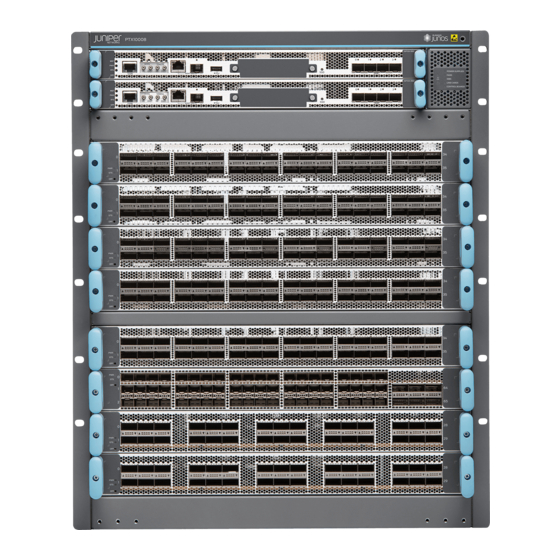
(NSR) providing software upgrades and changes without disrupting network traffic. Chassis Description The PTX10008 router is 13 U tall. Up to three PTX10008 routers can fit in a standard 42-U rack with adequate cooling and power. All key PTX10008 router components are field-replaceable units (FRUs). - Page 25 Figure 1: PTX10008 Chassis Front Routing and Control Boards Installation holes for the front panel — — Status LED panel Line card slots 0-7 (numbered top to bottom) — — Handles — Some chassis ship with an enhanced power bus to support the power needs of higher wattage line cards.
- Page 26 Figure 2: PTX10008 Chassis Rear FAN FTC SIB STATUS FAN FTC SIB STATUS AC or DC power supplies Fan trays with redundant fans — — Figure 3 on page 28 illustrates the components that are internal to the chassis.
-
Page 27: Routing And Control Board
The Routing and Control board (RCB) (see Figure 4 on page 29) contains a Routing Engine and is responsible for the system management and system control in the PTX10008. See “PTX10000 Routing and Control Board Description” on page 78. RCBs are FRUs that are installed in the front of the chassis in the slots labeled CB0 and CB1. -
Page 28: Line Cards
Figure 4: PTX10000 Routing and Control Board Line Cards The PTX10008 has eight horizontal line card slots and supports line rate for each line card. The line cards combine a Packet Forwarding Engine and Ethernet interfaces enclosed in a single assembly. PTX10008 line card architecture is based on a number of identical, independent Packet Forwarding Engine slices each with 500-Gbps full-duplex throughput. -
Page 29: Switch Interface Boards
30). A sixth SIB is available in the redundant configuration to provide n+1 redundancy. SIBs are installed between the line cards and the fan trays inside the chassis . Each PTX10008 SIB has eight connectors that match to a line card slot, eliminating the need for a backplane. See “PTX10008 Switch... -
Page 30: Cooling System
Figure 7: JNP10008-SF3 SIB Cooling System The cooling system in a PTX10008 router consists of two hot-removable and hot-insertable FRU fan trays (see Figure 8 on page 32) and two fan tray controllers (see Figure 9 on page 32). Two fan tray models and their associated fan tray controllers are available. Both models of fan tray contain 11 fans. -
Page 31: Power Supplies
Power supplies for the PTX10008 router are fully redundant, load-sharing, and hot-removable and hot-insertable FRUs. Each PTX10008 router with a base configuration has three power supplies; redundant configurations hold a maximum of six AC, high-voltage alternating current (HVAC), DC, or high-voltage direct current (HVDC) power supplies. - Page 32 Figure 10: JNP10K-PWR AC Power Supply Figure 11: JNP10K-PWR-AC2 Power Supply Figure 12: JNP10K-PWR-DC Power Supply...
-
Page 33: Software
Software The Juniper Networks PTX10000 line of Packet Transport Routers run Junos OS, which provides Layer 3 routing services. The same Junos OS code base that runs on the PTX10000 line of routers also runs on all Juniper Networks EX Series Ethernet Switches, M Series Multiservice Edge Routers, MX Series 5G universal Routing Platforms, and SRX Series Services Gateways. -
Page 34: Ptx10008 Components And Configurations
PTX10008 Components and Configurations Table 4 on page 35 lists the four hardware configurations for a PTX10008 modular chassis—base (AC and DC versions) and redundant (AC and DC versions)—and the components included in each configuration. Table 4: PTX10008 Hardware Configurations... - Page 35 Six SIBs Eight line card covers NOTE: You can install up to eight line cards (any combination of line cards) in the PTX10008. NOTE: Line cards and the cable management system are not part of the base or redundant configurations. You must order them separately.
-
Page 36: Ptx10008 Component Redundancy
PTX10008 Component Redundancy The PTX10008 router is designed so that no single point of failure can cause the entire system to fail. The following major hardware components in the redundant configuration provide redundancy: Routing and Control Board (RCB)—The RCB consolidates the Routing Engine function with control plane function in a single unit. -
Page 37: Line Cards
Line card (The Understanding Interface Naming the Flexible PIC of 0–7 for the router does Conventions Concentrator (FPC) PTX10008 and 0–15 for not have actual the PTX10016. The FPCs—the line On PTX10008, and value corresponds to the cards are the... -
Page 38: Ptx10000 Chassis
Description (CLI) Value (CLI) Documentation Additional Information Fan tray JNP10008-FAN or — Fan tray “PTX10008 Cooling System and JNP10008-FAN2 Airflow” on page 46 JNP10016-FAN or PTX10016 Cooling System JNP10016-FAN2 SIB (n) This field indicates: n is a value in the range... -
Page 39: Ptx10000 Field-Replaceable Units
RCB in the second slot. The system restarts to elect a master and backup. If necessary, you can switch the master and backup using the request chassis routing-engine master switch command. “PTX10008 Components and Configurations” on page 35 and PTX10016 Components and Configurations. -
Page 40: Ptx10000 Status Panel Leds
Line cards are not part of the base or redundant configuration. You must order them separately. NOTE: If you have a Juniper Care service contract, register any addition, change, or upgrade of hardware components at https://www.juniper.net/customers/support/tools/updateinstallbase/. Failure to do so can result in significant delays if you need replacement parts. This note does not apply if you replace an existing component with the same type of component. - Page 41 Indicates the type of power bus internal to the chassis Some chassis ship with an enhanced power bus to support the power needs of higher wattage line cards. The status panel indicates the chassis status through a set of five bi-color LEDs. See Figure 14 on page 42 for a chassis status panel with the original power bus.
- Page 42 Table 7: Status Panel LEDs in a PTX10000 Name Color State Description Power supplies Green On steadily All of the power supplies are online and operating normally. Yellow Blinking One or more of the power supplies has an error. None None of the power supplies is receiving power.
-
Page 43: Ptx10000 Optional Equipment
SEE ALSO PTX10000 Routing and Control Board Components and Descriptions | 78 PTX10000 Line Card Components and Descriptions | 90 PTX10008 Switch Fabric | 85 PTX10000 Power System | 61 PTX10000 Optional Equipment IN THIS SECTION PTX10000 Cable Management System | 44... - Page 44 Cables are draped across or under the handle extensions and then secured with cable wraps (see Figure 18 on page 45). Figure 18: Two Cable Management Systems Installed on PTX10008 SEE ALSO Installing the PTX10000 Cable Management System | 344...
-
Page 45: Ptx10008 Cooling System
Airflow Direction in the PTX10008 | 52 The cooling system in a PTX10008 chassis consists of dual fan trays with matching dual fan tray controllers. Two fan tray models and their associated fan tray controllers are available. All models are hot-insertable and hot-removable. - Page 46 Two handles on each front faceplate are available to help remove or replace fans. See. Figure 19 on page 47 Figure 20 on page Figure 19: Installed JNP10008-FAN with JNP10K-PWR-AC Power Supplies in a PTX10008 FAN FTC SIB STATUS FAN FTC...
- Page 47 Figure 20: Installed JNP10008-FAN2, with JNP10K-PWR-AC2 Power Supplies in an PTX10008 Router Power supplies Fan trays — — Table 8 on page 48 for the physical specifications for the fan trays. Table 8: Fan Tray Specifications Specification JNP10008-FAN JNP10008-FAN2 Corresponding fan tray controller...
-
Page 48: Fan Tray Controllers
Table 8: Fan Tray Specifications (continued) Specification JNP10008-FAN JNP10008-FAN2 Depth 4.0 in. (10.2 cm) without handles, 5.5 in. (13.97 cm) without handles, 5.2 in. (13.2 cm) with handles 6.7 in. (17.01 cm) with handles Weight 11.8 lb (5.4 kg) 20 lbs (9.07 kg) If you want to replace an existing fan tray while the router is running, remove only one fan tray. - Page 49 Figure 22: Fan Controller JNP10008-FTC2 WARNING: Do not mix the fan tray controller models. Use only the supported fan model for each fan tray controller. The system continually monitors the temperature of critical parts across the chassis and adjusts the chassis fan speed according to the temperature.
- Page 50 Fan Tray 1 Fan 6 6150 Spinning at normal speed Fan Tray 1 Fan 7 6150 Spinning at normal speed Fan Tray 1 Fan 8 6150 Spinning at normal speed Fan Tray 1 Fan 9 6150 Spinning at normal speed Fan Tray 1 Fan 10 6300 Spinning at normal speed...
-
Page 51: Airflow Direction In The Ptx10008
1.5 lb (0.68 kg) 1.1 lb (0.5 kg) Airflow Direction in the PTX10008 The air intake to cool the chassis is located on the port (line card) side of the chassis. Air flows into the chassis from the ports in the control boards and line cards, through the switch interface boards (SIBs), and exits from the fan trays and the power supplies. -
Page 52: Ptx10000 Fan Tray Leds And Fan Tray Controller Leds
Figure 23: Airflow Through a PTX10008 The fan tray continues to operate indefinitely and provide sufficient cooling even when a single fan fails, provided the room temperature is within the operating range. You can check the status of fans by viewing the LEDs on each fan tray. -
Page 53: Fan Tray Leds
Each fan tray has a set of LEDs, and each corresponding fan tray controller also has a set of LEDs. Fan Tray LEDs The two fan trays have a set of LEDs that represent the status of the fans in the fan tray, the fan tray controller, and the three Switch Interface Boards (SIBs). - Page 54 Figure 25: Fan Tray JNP10008-FAN2 and JNP10016 LEDs Fan status LED SIB status (SIB 0 through SIB 2 for the left fan tray — — and SIB 3 through 5 for the right fan tray). Fan tray controller status — Table 10 on page 55 describes the functions of the fan tray LEDs.
- Page 55 Table 10: Fan Tray LEDs on a PTX10000 Router (continued) Name Color State Description Fan tray controller status Green On steadily The fan tray controller is online and is operating normally. Green Blinking The beacon feature is enabled. This feature is enabled using the request chassis beacon command.
- Page 56 Table 10: Fan Tray LEDs on a PTX10000 Router (continued) Name Color State Description SIB 1 status Green On steadily The center SIB behind the left fan tray is online. Green Blinking The beacon feature is enabled. This feature is enabled using the request chassis beacon command.
- Page 57 Table 10: Fan Tray LEDs on a PTX10000 Router (continued) Name Color State Description SIB 3 status Green On steadily The left-most SIB behind the right fan tray is online. Green Blinking The beacon feature is enabled. This feature is enabled using the request chassis beacon command.
-
Page 58: Fan Tray Controller Leds
Table 10: Fan Tray LEDs on a PTX10000 Router (continued) Name Color State Description SIB 5 status Green On steadily The right-most SIB behind the right fan tray is online. Green Blinking The beacon feature is enabled. This feature is enabled using the request chassis beacon command. - Page 59 Table 11: Fan Tray Controller LEDs on a PTX10000 Name Color State Description Fan controller power Green On steadily The fan tray controller has power and is operating normally. Yellow Blinking A power error has been detected in the fan tray controller. Replace the fan tray controller as soon as possible.
-
Page 60: Ptx10000 Power System
JNP10K-PWR-DC2 Power Supply LEDs | 76 You can install up to six power supplies in a PTX10008 router in the slots labeled PEM 0 through PEM 5 (top to bottom) located in the rear of the chassis. In the PTX10016, you can install up to 10 power supplies in the slots labeled PEM 0 through PEM 9 (top to bottom) located in the rear of the chassis. -
Page 61: Jnp10K-Pwr-Ac Power Supply
Using a grounding cable with an incorrectly attached lug can damage the router. All base configuration PTX10008 routers are shipped with three power supplies; base configuration PTX10016 routers are shipped with five power supplies. Cover are installed over the remaining power supply slots. - Page 62 Each JNP10K-PWR-AC power supply comes with two power cord retainers that hold the power cords in place. See Figure 28 on page 63. Each power cord retainer has a clip and an adjustment nut. The ends of the clip hook into the bracket holes on each side of the AC appliance inlet on the faceplate. The adjustment nut holds the power cord in the correct position.
-
Page 63: Jnp10K-Pwr-Ac2 Power Supply
JNP10K-PWR-AC2 Power Supply The JNP10K-PWR-AC2 power supply is a high-capacity, high-line model that is designed to support either AC or DC systems in either a low power or high power mode. The power supply takes AC input and provides DC output of 12.3 VDC, 5000 W with a single feed and 5500 W with a dual feed. For AC systems, the operating input voltage is 180 to 305 VAC and for DC systems, the operating input voltage is 190 to 410 VDC. -
Page 64: Jnp10K-Pwr-Dc Power Supply
CAUTION: Before you begin installing the router, ensure that a licensed electrician has attached an appropriate grounding lug to the grounding cable that you supply. Using a grounding cable with an incorrectly attached lug can damage the router. Table 12: Power Input and Output Voltages for JNP10K-PWR-AC2 Power Supplies H/L (High Input 30 A/Low Input INP0 (Switch 1) INP1 (Switch 2) - Page 65 All three power supplies fit into a power slot bay, but the JNP10K-PWR-AC2 and JNP10K-PWR-DC2 are longer and protrude from the bay when fully inserted into the chassis. See Figure 30 on page Figure 30: Size Comparison Between JNP10K-PWR-DC and JNP10K-PWR-DC2 Power Supplies CAUTION: Do not mix power supply models in the same chassis in a running environment.
- Page 66 NOTE: DC power supplies are shipped only in the redundant configuration of PTX10000 routers. For details about different chassis configurations, see “PTX10008 Components and Configurations” on page 35 and PTX10016 Components and Configurations. Each JNP10K-PWR-DC power supply weighs approximately 6 lb (2.7 kg) and has two independent pairs of DC input lugs (Input 1, RTN, –48V/–60V and Input 2, RTN, –48V/–60V) on the faceplate of the power...
-
Page 67: Jnp10K-Pwr-Dc2 Power Supply
DC feed. The chosen breaker should be sized to deliver 60 A of input current. Each power supply connects to the combined power rail in a PTX10008 router or a PTX10016 router. The power rail distributes the output power produced by the power supplies to different router components. - Page 68 Table 13: Power Input and Output Voltages for JNP10K-PWR-DC2 Power Supplies H/L (High Input 80 A/Low Input INP0 (Switch 1) INP1 (Switch 2) 60A) Output Power On (80 A) 5500 W Off (60 A) 4400 W On (80 A) 2750 W On (80 A) 2750 W Off (60 A)
-
Page 69: Jnp10K-Pwr-Ac Power Supply Leds
NOTE: DC power supplies are shipped only in the redundant configuration of PTX10000 routers. For details about different chassis configurations, see “PTX10008 Components and Configurations” on page 35 and PTX10016 Components and Configurations. JNP10K-PWR-DC2 models can use the standard bus or the enhanced bus. The enhanced bus supports the full 5500 W available from the JNP10K-PWR-DC2. - Page 70 Figure 33: LEDs on an JNP10K-PWR-AC Power Supply FAULT INP2–Source input 1 — — PWR OK INP1–Source input 0 — — Table 14 on page 71 describes the LEDs on a JNP10K-PWR-AC power supply. Table 14: LEDs on a JNP10K-PWR-AC Power Supply Color State Description...
-
Page 71: Jnp10K-Pwr-Ac2 Power Supply Leds
If the INP1 or INP2 LED is lit and the PWR OK LED is unlit, the AC power supply is not installed properly or the power supply has an internal failure. SEE ALSO Power Requirements for PTX10000 Components | 165 PTX10008 Power Planning PTX10000 Power Cables Specifications | 172 Connecting AC Power to a PTX10000 | 235 JNP10K-PWR-AC2 Power Supply LEDs The JNP10K-PWR-AC2 power supply has four LEDs on its faceplate: !, OK, 2, and 1. - Page 72 Figure 34: LEDs on a JNP10K-PWR-AC2 HVAC?HVDC Power Supply ! FAULT 2 INP2–Source input 1 — — OK PWR OK 1 INP1–Source input 0 — — NOTE: Physical markings on the power supply are INP1 and INP2. These markings correspond to INP0 and INP1 in the show chassis power output (see Table 15 on page 73).
-
Page 73: Jnp10K-Pwr-Dc Power Supply Leds
Table 16: Interpreting JNP10K-PWR-AC2 LEDs Color State Description INP1 or INP0 in CLI output Yellow Blinking The input voltage is present, but is not within normal operating range. Green Solid The input voltage is present and within normal operating range. Unlit The power supply is switched off;... - Page 74 Figure 35: LEDs on a JNP10K-PWR-DC Power Supply INP1–Source input 0 PWR OK — — INP2–Source input 1 FAULT — — Table 17 on page 75 describes the LEDs on JNP10K-PWR-DC power supplies. Table 17: LEDs on a JNP10K-PWR-DC Power Supply Color State Description...
-
Page 75: Jnp10K-Pwr-Dc2 Power Supply Leds
If the FAULT LED is blinking, add a power supply to balance the power demand and supply. SEE ALSO Power Requirements for PTX10000 Components | 165 PTX10008 Power Planning Connecting DC Power to a PTX10000 | 235 JNP10K-PWR-DC2 Power Supply LEDs A JNP10K-PWR-DC2 power supply module has four LEDs on its faceplate: 1, 2, OK, and the symbol for fault, !. - Page 76 Table 18 on page 77 describes the LEDs on a JNP10K-PWR-DC2 power supply. Table 18: LEDs on a JNP10K-PWR-DC2 Power Supply Color State Description 1 (INP0 in CLI output) or 2 Yellow Blinking Indicates the DC power input voltage is not within (INP1 in CLI output) normal operating range.
- Page 77 PTX10000 Routing and Control Board LEDs | 81 The PTX10008 and PTX10016 host subsystem comprises the Routing and Control Board (RCB). The RCB is an integrated board and a single FRU that provides Routing Engine (RE) and Control Board (CB) functionality.
- Page 78 JNP10K-RE1-LT JNP10K-RE1-128G Figure 37: PTX10000 Routing and Control Board (JNP10K-RE0) Figure 38: PTX10000 Routing and Control Board (JNP10K-RE1 and JNP-RE1-128) JNP10K-RE1-128 JNP10K-RE1-128 MASTER This topic covers: Routing and Control Board Functions The Routing and Control Board integrates the control plane and Routing Engine functions into a single management unit.
- Page 79 Routing and Control Board Components Each RCB consists of the following internal components: Quad-core 2.5 GHz CPU 32 gigabytes SDRAM SATA SSD Other standard interfaces are shown in Figure 39 on page Figure 39: Routing and Control Board Faceplate (JNP10K-RE0) RCB status LEDs USB 2.0 port —...
- Page 80 SEE ALSO Handling and Storing PTX10000 Line Cards, Routing and Control Boards, and SIBs | 321 Installing a PTX10000 Routing and Control Board | 247 PTX10000 Routing and Control Board LEDs IN THIS SECTION Routing and Control Board Status Panel LEDs | 82 PTX10000 Management Port LEDs | 83 SATA SSD LEDs | 84 Clock LEDs (JNP10K-RE1, JNP10K-RE1-LT, and JNP10K-RE1-128) | 85...
- Page 81 This topic covers: Routing and Control Board Status Panel LEDs The RCB status panel LEDs indicate the state of the RCB (see Figure 43 on page 82). Figure 43: Routing and Control Board Status Panel LEDs Power (PWR) LED Master (MST) LED —...
- Page 82 PTX10000 Management Port LEDs The two management ports on the RCB of a PTX10008 router and a PTX10016 router have LEDs that indicate link status and link activity. These two ports, located on the RCB panel between the clocking connections and the USB port, are both labeled MGMT. The left management port is for 10/100/1000...
- Page 83 Table 21: SFP Management Port LEDs on a PTX10000 Routing and Control Board (JNP10K-RE0 and JNP10K-RE1) Color State Description Link/Activity/Status Unlit No transceiver is present. Green On steadily A link is established. The interface is up. Green Blinking or flickering The beacon feature is enabled.
- Page 84 Installing a PTX10000 Routing and Control Board | 247 PTX10008 Switch Fabric IN THIS SECTION PTX10008 Switch Interface Board Description | 86 PTX10000 Switch Interface Board LEDs | 88 The PTX10000 Switch Interface Boards (SIBs) form the switch fabric for the router.
- Page 85 See Figure 45 on page Figure 45: SIB The SIBs make up the PTX10008 switching plane. There are two models of SIBs: the standard SIB (see Figure 45 on page 86) and the enhanced SIB (see Figure 46 on page 87).
- Page 86 Figure 46: Enhanced SIB for 14.4 Terabyte Line Cards Table 25 on page 87 shows the physical specifications for a PTX10008 SIB. Table 25: Dimensions of a PTX10008 SIB Specification Value Height 19.7 in. (50.04 cm) Width 1.8 in. (4.57 cm) Depth 10.4 in.
- Page 87 Figure 47: SIBs Installed in a PTX10008 Fan tray controllers SIBs — — SEE ALSO Installing a PTX10000 Switch Interface Board | 326 Removing a PTX10000 Switch Interface Board | 332 PTX10000 Switch Interface Board LEDs The Switch Interface Board (SIB) has two status LEDs at the top of each board. See...
- Page 88 Figure 48: SIB LEDs Table 26 on page 89 describes the functions of these LEDs. Table 26: SIB LEDs Label Color State Description Green On steadily The SIB is receiving power. Yellow Blinking Power fault. Unlit The SIB is either offline or not receiving power. STAT Green On steadily...
- Page 89 QFX10000-60S-6Q Line Card in PTX10008 and PTX10016 Routers | 137 PTX10000 Line Card LEDs | 144 The PTX10008 chassis supports up to eight line cards and the PTX10016 chassis supports 16 line cards. Table 27 on page Table 27: Line Card Summary...
- Page 90 Table 27: Line Card Summary (continued) Line Card Description Dimensions Weight PTX10K-LC1105 30-port 100-Gigabit or 40-Gigabit Ethernet 17.2 in x 1.89 in x 20.5 28.5 lbs with MACsec 12.93 kg 43.68 cm x 4.8 cm x 52.07 cm QFX10000-60S-6Q 60-port 10-Gigabit or 1-Gigabit Ethernet; 17.2 in x 1.89 in x 20.5 9.7 lbs 2-port of 40-Gigabit or 100-Gigabit Ethernet;...
- Page 91 common naming convention, where JNP10K-LC1101 is the name used on the overlay for the LC1101 line card. See Figure 49 on page Figure 49: PTX10K-LC1101 Port Panel Status and activity LEDs Network ports — — Each QSFP28 socket supports: 100-Gigabit Ethernet using QSFP28 optical transceivers. When a QSFP28 transceiver is inserted into any of the ports, the QSFP28 socket is enabled for 100-Gigabit Ethernet.
- Page 92 Table 28: Maximum Port Configuration (continued) Port Speed Non-Channelized Mode (Mode D) Channelized Mode (Mode A) 40 Gbps 24 or 10 Gbps Unlike the PTX10K-LC1102 line card, the PTX10K-LC1101 line card does not have port groups; instead, port behavior is tied to the ASIC associated with the port. You must configure each port individually, in order to channelize a 40-Gigabit Ethernet port to 4 independent 10-Gigabit Ethernet ports.
- Page 93 To change from the default mode to 40-Gigabit Ethernet channelized mode, use the Junos OS operational command set chassis fpc slot-number pic 0 port port number channelization-speed 10g. Network Ports Each of the 30 QSFP28 ports supports: 100-Gigabit Ethernet QSFP28 transceivers 40-Gigabit Ethernet QSFP+ transceivers PTX10K-LC1102 Line Card IN THIS SECTION...
- Page 94 Figure 51: PTX10K-LC1102 Port Panel Status and activity LEDs Network ports — — Each QSFP28 socket can be configured to support: 100-Gigabit Ethernet using QSFP28 optical transceivers. When a QSFP28 transceiver is inserted into the ports marked with a fine black line underneath the socket and the port is configured for 100-Gigabit Ethernet, the two adjacent ports are disabled and the QSFP28 socket is enabled for 100-Gigabit Ethernet.
- Page 95 Figure 52: All Ports Are Enabled for Channelized 4x10-Gigabit Ethernet by Default All por t s can be u sed as 40-Gi gabit Ethern et Figure 53: 100-Gigabit Ethernet Ports 100-Gi gabit Ethern et por t s Disab led when 100-Gi gabit Ethern et por t s are used Figure 54: 100-Gigabit Ethernet Port Disables Two Associated 40-Gigabit Ethernet Ports The 40-Gigabit Ethernet ports can operate independently, be channelized into four 10-Gigabit Ethernet...
- Page 96 Figure 55: Use the First and Fourth Port in Each 6XQSFP Cage to Channelize a Port Range Port 0 Port 3 Use every third port to create a port range for 40-Gigabit Channelization. Table 30 on page 97 shows the available combinations for the ports. On the LC1102, the ports are enabled by default.
- Page 97 Table 30: PTX10K-LC1102 Port Mapping (continued) 4X10-Gigabit 4X10-Gigabit Channelized 40-Gigabit 100-Gigabit 100-Gigabit Ethernet Port Number Ethernet Port Group Ethernet Ethernet Disables – – 12, 14 – – – – – – 15, 16 – – 18, 20 – – – –...
- Page 98 Alarms, Errors, and Events | 107 OT and ET Interface Alarms and Defects | 113 The PTX10K-LC1104 line card runs Juniper Networks Junos OS for PTX Series software on Juniper Networks JNP10K-LC1104 hardware. The PTX10k-LC1104 line card provides up to 1.2 Tbps of packet forwarding for cloud providers, service providers, and enterprises that need coherent dense wavelength-division multiplexing (DWDM) with MACsec security features.
- Page 99 PTX10K-LC1104 coherent line cards are supported in all models of the PTX10000 Packet Transport Router. The PTX10K-LC1104 line card is supported on Junos OS Release 17.4R1-S1 and later on PTX10008 and Junos OS Release 18.3R1 on PTX10016. This topic includes:...
- Page 100 Figure 57: PTX10K-LC1104 Interfaces NOTE: All optical properties are configured under the ot interface. Use the set interfaces ot-x/x/x optics-options CLI command to set these options. Perform MACsec configuration on the et interface using the set security macsec connectivity-association ca-name encryption-algorithm. Optical transport network (OTN) related configurations also are done on the et interface.
-
Page 101: Compatibility
The Juniper Networks Open Cloud Interconnect solution includes integrated 100-GbE coherent optics on Juniper Networks QFX Series switches; MX Series 5G Universal Routing Platforms and PTX Series Packet Transport Routers; and BTI Packet Optical Platforms optimized for DCI. As part of the Open Cloud Interconnect solution, the PTX10K-LC1104 coherent line card is compatible with many third-party optical products as well as Juniper Networks optical solutions and offerings. -
Page 102: Optical Receive Specifications
Table 33: PTX10K-LC1104 Optical Transmit Specifications (continued) Specification Value Modulation format DP-QPSK, DP-8QAM, DP-16QAM Line rate DP-QPSK = 136.66 Gbps DP-8QAM = 205 Gbps DP-16QAM= 273.33 Gbps FEC types 15% or 25% SDFEC Channel-plan wavelength range Extended C-band, 1528.77 nm to 1566.72 nm Channel-plan frequency range 196.1 THz to 191.35 THz Channel spacing... -
Page 103: Status And Activity Leds
Table 34: PTX10k-LC1104 Optical Receive Specifications (continued) Specification 100G DP-PSK 150G DP-8QAM 200G DP-16QAM Optical receiver damage input power +17 dBm +17 dBm +17 dBm threshold Optical receiver minimum OSNR 10.3 dB 14.7 dB 17.6 dB (back-to-back), typical Optical receiver minimum OSNR 11.5 dB 16.0 dB 19.0 dB... - Page 104 Table 35: Network Port Status LEDs (ot Interfaces) Color Description Unlit The port is not configured. Solid green A link is established on the ot interface. Solid amber The optical module associated with the port has a fault condition, or the port is configured but the link is down. You can also determine the configuration of the et interfaces by examining the pattern of the four Ethernet LEDs.
-
Page 105: Software Features
Software Features Compliance with ITU G.709 and G.798 Transport interface and state model (GR-1093) Performance monitoring features such as alarms, threshold-crossing alarms, OTU/ODU error seconds, and FEC and bit error rate (BER) statistics SNMP management of the MIC based on RFC 3591, Managed Objects for the Optical Interface Type, including the following: Black Link MIB–jnx-bl.mib IFOTN MIB–jnx-ifotn.mib... -
Page 106: Alarms, Errors, And Events
Alarms, Errors, and Events Chassis and Line Card Alarms NOTE: For ot and et alarms, see Table 38 on page 113 Table 39 on page 114. Chassis and line card: Line card (FRU) inserted or removed Line card (FRU) Administrative State: In Service, Out Of Service Line card (FRU) Operational State: Unequipped, Init, Normal, Mismatch, Fault, Upgrade Mismatch equipment Temperature alarm... - Page 107 Module fault alarm PLD Flash initialization fault alarm Power supply fault alarm Checksum fault alarm RX CDR loss of lock alarm TEC fault alarm Wavelength unlocked alarm TX loss of signal functionality alarm TX CDR loss of lock alarm RX loss of signal alarm Module temp fault Specific hardware fault Internal power fault...
- Page 108 ITLA fault DAC calib fault ADC calib fault PROM fault TX mod bias VOA ctrl loop high alarm TX mod bias VOA ctrl loop low alarm TX jitter PLL LOL TX out of alignment TX CMU lock fault ADC signal below threshold TX output power adjustment fault TX output mod converge fault TX laser ready fault...
- Page 109 High warning Low warning TX laser output power alarm High alarm Low alarm High warning Low warning TX laser temperature alarm: High alarm Low alarm High warning Low warning TX laser bias current alarm: High alarm Low alarm High warning Low warning TX modulator bias current alarm: High alarm...
- Page 110 High warning Low warning RX phase control loop High alarm Low alarm High warning Low warning TIP: You can view optics-related status by using the show interfaces diagnostics optics operational-mode CLI commands. OT Interface Network Lane Performance Monitoring Status Messages Network lane receive-related status: Chromatic dispersion: Current chromatic dispersion...
- Page 111 Current SNR Minimum over PM interval Maximum over PM interval Average over PM interval Carrier frequency offset Current carrier frequency offset Minimum over PM interval Maximum over PM interval Average over PM interval TX output power Current TX output power Minimum over PM interval Maximum over PM interval Average over PM interval...
-
Page 112: Ot And Et Interface Alarms And Defects
FEC statistics: Corrected Errors—The number of bits received that were in error, but corrected. Uncorrected Words—The number of FEC codewords received that were not correctable. Corrected Error Ratio—The number of corrected bits divided by the number of bits received. TIP: You can view FEC statistics by using the show interfaces interface-name extensive operational-mode CLI command. - Page 113 Table 38: OT Interface Alarms and Defects (continued) Category Alarm Description Link Status Optics Module fault Module fault state Link down Optical RX modem synch fault Modem sync detect fault Link down Channel RX modem loss of lock OTU-BDI Modem lock fault Link down RX loss of alignment Loss of alignment fault...
- Page 114 Table 39: ET Interface Alarms and Defects (continued) Category Alarm Description Link Status OTN OTU OTU-AIS Alarm indication signal or all ones signal Alarm OTU-BDI Backward defect identification Alarm OTU-IAE Incoming alignment error Warning OTU-TTIM Destination access point identifier (DAPI), source Warning access point identifier (SAPI), or both mismatch from expected to received...
- Page 115 MACsec ports with built-in long-reach optics. DWDM channel frequency offsets are 0.02 THz. The QFX10000-12C-DWDM line card is available for QFX10008 and QFX10016 switch chassis running Junos Os Release 17.3R1 and later. The PTX10K-1104 coherent line card is available for PTX10008 and PTX10016 line cards. See Table 40 on page 116 for the available channel frequencies and wavelengths.
- Page 116 Table 40: DWDM Module Wavelengths (continued) Frequency (THz) Wavelength (nm) Offset 191.53 1565.29 12.5 GHz 191.54 1565.19 12.5 GHz 191.55 1565.09 12.5/50 GHz 191.56 1564.99 12.5 GHz 191.58 1564.88 12.5 GHz 191.59 1564.78 12.5 GHz 191.6 1564.68 12.5/50/100 GHz 191.61 1564.58 12.5 GHz 191.63...
- Page 117 Table 40: DWDM Module Wavelengths (continued) Frequency (THz) Wavelength (nm) Offset 191.79 1563.15 12.5 GHz 191.8 1563.05 12.5/50/100 GHz 191.81 1562.95 12.5 GHz 191.83 1562.84 12.5 GHz 191.84 1562.74 12.5 GHz 191.85 1562.64 12.5/50 GHz 191.86 1562.54 12.5 GHz 191.88 1562.44 12.5 GHz 191.89...
- Page 118 Table 40: DWDM Module Wavelengths (continued) Frequency (THz) Wavelength (nm) Offset 192.05 1561.01 12.5/50 GHz 192.06 1560.91 12.5 GHz 192.08 1560.81 12.5 GHz 192.09 1560.71 12.5 GHz 192.1 1560.61 12.5/50/100 GHz 192.11 1560.51 12.5 GHz 192.13 1560.4 12.5 GHz 192.14 1560.3 12.5 GHz 192.15...
- Page 119 Table 40: DWDM Module Wavelengths (continued) Frequency (THz) Wavelength (nm) Offset 192.31 1558.88 12.5 GHz 192.33 1558.78 12.5 GHz 192.34 1558.68 12.5 GHz 192.35 1558.58 12.5/50 GHz 192.36 1558.48 12.5 GHz 192.38 1558.38 12.5 GHz 192.39 1558.27 12.5 GHz 192.4 1558.17 12.5/50/100 GHz 192.41...
- Page 120 Table 40: DWDM Module Wavelengths (continued) Frequency (THz) Wavelength (nm) Offset 192.58 1556.76 12.5 GHz 192.59 1556.66 12.5 GHz 192.6 1556.56 12.5/50/100 GHz 192.61 1556.45 12.5 GHz 192.63 1556.35 12.5 GHz 192.64 1556.25 12.5 GHz 192.65 1556.15 12.5/50 GHz 192.66 1556.05 12.5 GHz 192.68...
- Page 121 Table 40: DWDM Module Wavelengths (continued) Frequency (THz) Wavelength (nm) Offset 192.84 1554.64 12.5 GHz 192.85 1554.54 12.5/50 GHz 192.86 1554.44 12.5 GHz 192.88 1554.34 12.5 GHz 192.89 1554.24 12.5 GHz 192.9 1554.13 1554.134 192.91 1554.03 12.5 GHz 192.93 1553.93 12.5 GHz 192.94 1553.83...
- Page 122 Table 40: DWDM Module Wavelengths (continued) Frequency (THz) Wavelength (nm) Offset 193.1 1552.52 12.5/50/100 GHz 193.11 1552.42 12.5 GHz 193.13 1552.32 12.5 GHz 193.14 1552.22 12.5 GHz 193.15 1552.12 12.5/50 GHz 193.16 1552.02 12.5 GHz 193.18 1551.92 12.5 GHz 193.19 1551.82 12.5 GHz 193.2...
- Page 123 Table 40: DWDM Module Wavelengths (continued) Frequency (THz) Wavelength (nm) Offset 193.36 1550.42 12.5 GHz 193.38 1550.32 12.5 GHz 193.39 1550.22 12.5 GHz 193.4 1550.12 12.5/50/100 GHz 193.41 1550.02 12.5 GHz 193.43 1549.92 12.5 GHz 193.44 1549.82 12.5 GHz 193.45 1549.72 12.5/50 GHz 193.46...
- Page 124 Table 40: DWDM Module Wavelengths (continued) Frequency (THz) Wavelength (nm) Offset 193.63 1548.32 12.5 GHz 193.64 1548.22 12.5 GHz 193.65 1548.12 12.5/50 GHz 193.66 1548.02 12.5 GHz 193.68 1547.92 12.5 GHz 193.69 1547.82 12.5 GHz 193.7 1547.72 12.5/50/100 GHz 193.71 1547.62 12.5 GHz 193.73...
- Page 125 Table 40: DWDM Module Wavelengths (continued) Frequency (THz) Wavelength (nm) Offset 193.89 1546.22 12.5 GHz 193.9 1546.12 12.5/50/100 GHz 193.91 1546.02 12.5 GHz 193.93 1545.92 12.5 GHz 193.94 1545.82 12.5 GHz 193.95 1545.72 12.5/50 GHz 193.96 1545.62 12.5 GHz 193.98 1545.52 12.5 GHz 193.99...
- Page 126 Table 40: DWDM Module Wavelengths (continued) Frequency (THz) Wavelength (nm) Offset 194.15 1544.13 12.5/50 GHz 194.16 1544.03 12.5 GHz 194.18 1543.93 12.5 GHz 194.19 1543.83 12.5 GHz 194.2 1543.73 12.5/50/100 GHz 194.21 1543.63 12.5 GHz 194.23 1543.53 12.5 GHz 194.24 1543.43 12.5 GHz 194.25...
- Page 127 Table 40: DWDM Module Wavelengths (continued) Frequency (THz) Wavelength (nm) Offset 194.41 1542.04 12.5 GHz 194.43 1541.94 12.5 GHz 194.44 1541.85 12.5 GHz 194.45 1541.75 12.5/50 GHz 194.46 1541.65 12.5 GHz 194.48 1541.55 12.5 GHz 194.49 1541.45 12.5 GHz 194.5 1541.35 12.5/50/100 GHz 194.51...
- Page 128 Table 40: DWDM Module Wavelengths (continued) Frequency (THz) Wavelength (nm) Offset 194.68 1539.96 12.5 GHz 194.69 1539.87 12.5 GHz 194.7 1539.77 12.5/50/100 GHz 194.71 1539.67 12.5 GHz 194.73 1539.57 12.5 GHz 194.74 1539.47 12.5 GHz 194.75 1539.37 12.5/50 GHz 194.76 1539.27 12.5 GHz 194.78...
- Page 129 Table 40: DWDM Module Wavelengths (continued) Frequency (THz) Wavelength (nm) Offset 194.94 1537.89 12.5 GHz 194.95 1537.79 12.5/50 GHz 194.96 1537.69 12.5 GHz 194.98 1537.59 12.5 GHz 194.99 1537.5 12.5 GHz 1537.4 12.5/50/100 GHz 195.01 1537.3 12.5 GHz 195.03 1537.2 12.5 GHz 195.04 1537.1...
- Page 130 Table 40: DWDM Module Wavelengths (continued) Frequency (THz) Wavelength (nm) Offset 195.2 1535.82 12.5/50/100 GHz 195.21 1535.72 12.5 GHz 195.23 1535.63 12.5 GHz 195.24 1535.53 12.5 GHz 195.25 1535.43 12.5/50 GHz 195.26 1535.33 12.5 GHz 195.28 1535.23 12.5 GHz 195.29 1535.13 12.5 GHz 195.3...
- Page 131 Table 40: DWDM Module Wavelengths (continued) Frequency (THz) Wavelength (nm) Offset 195.46 1533.76 12.5 GHz 195.48 1533.66 12.5 GHz 195.49 1533.56 12.5 GHz 195.5 1533.47 12.5/50/100 GHz 195.51 1533.37 12.5 GHz 195.53 1533.27 12.5 GHz 195.54 1533.17 12.5 GHz 195.55 1533.07 12.5/50 GHz 195.56...
- Page 132 Table 40: DWDM Module Wavelengths (continued) Frequency (THz) Wavelength (nm) Offset 195.73 1531.7 12.5 GHz 195.74 1531.61 12.5 GHz 185.75 1531.51 12.5/50 GHz 185.76 1531.41 12.5 GHz 195.78 1531.31 12.5 GHz 195.79 1531.21 12.5 GHz 195.8 1531.12 12.5/50/100 GHz 195.81 1531.02 12.5 GHz 195.83...
- Page 133 Table 40: DWDM Module Wavelengths (continued) Frequency (THz) Wavelength (nm) Offset 195.99 1529.65 12.5 GHz 1529.55 12.5/50/100 GHz 196.01 1529.46 12.5 GHz 196.03 1529.36 12.5 GHz 196.04 1529.26 12.5 GHz 196.05 1529.16 12.5/50 GHz 196.06 1529.07 12.5 GHz 196.08 1528.97 12.5 GHz 196.09 1528.87...
- Page 134 Control Security (MACsec) capable. The ports support speeds of 100 Gbps or 40 Gbps and you can configure the port speed through the CLI. The PTX10K-LC1105 line card is supported on Junos OS Release 17.4R1-S1 and later. This topic describes: Overview The line cards in PTX10000 Packet Transport Routers combine a Packet Forwarding Engine and Ethernet interfaces in a single assembly.
- Page 135 Table 41: Power LED Color State Description Unlit There is no power to the line card. Green On steadily The line card has power. Yellow or amber Blinking The line card has a power fault. Table 42: Status LED Color State Description Unlit...
- Page 136 A single LED blinking indicates an interface fault. SEE ALSO PTX10000 Field-Replaceable Units | 40 Installing a PTX10000 Line Card | 338 QFX10000-60S-6Q Line Card in PTX10008 and PTX10016 Routers IN THIS SECTION Hardware Features | 138 Port Groups | 139...
- Page 137 This topic describes: Hardware Features The line cards in PTX10008 and PTX10016 routers combine a Packet Forwarding Engine and Ethernet interfaces in a single assembly. Line cards are field-replaceable units (FRUs) that can be installed in the line card slots on the front of the chassis. The line cards are hot-insertable and hot-removable; you can remove and replace them without powering off the router or disrupting router functions.
- Page 138 Each QSFP28 port (60 and 64) controls a port group and can be configured to support: 100-Gigabit Ethernet using QSFP28 optical transceivers. The interface speeds are configured by port group. When a QSFP28 transceiver is inserted into the one of the QSFP28 ports marked with a fine black line above the port (60 or 64) and the port is configured for 100-Gigabit Ethernet, the two adjacent ports are disabled and the QSFP28 port is enabled for 100-Gigabit Ethernet.
- Page 139 Figure 62 on page 140 shows the location of QSFP28 ports and port groups for the QFX10000-60S-6Q. Table 44 on page 140 shows the available combinations for the ports. Figure 62: QFX10000-60S-6Q Port Groups Table 44: QFX10000-60S-6Q Port Mapping 4X10-Gigabit 4X10-Gigabit Channelized 40-Gigabit...
- Page 140 user@router# set port 60 speed 10g Review your configuration and issue the commit command. If you want to return the port to the default, delete the speed statement from the configuration at the [chassis fpc 6 pic 1 port port-number] hierarchy level and commit the configuration. The network port is reset to the default 40-Gigabit Ethernet interface.
- Page 141 Figure 64: Belly-to-Belly SFP Transceivers Recommended configuration SFP+ Status and Activity LEDs All status and activity LEDs for the SFP+ ports are located between the second and third rows of SFP+. The up arrow, circle, and down arrow indicate the row of the status. A bi-color LED indicates the status and activity.
- Page 142 Table 45: Network Port Status and Activity LEDs for SFP+ Ports on a QFX10000-60S-6Q Line Card (continued) Color State Description Yellow or Amber Slow blink, or blip The beacon function is enabled on one or more sub-channels. Blinking The interface has a fault condition. QSFP+ and QSFP28 Status and Activity LEDs All QSFP+ and QSFP28 ports have an up or down indicator for each port and four bi-colored LEDs that show port status and link activity based on whether or not the port is configured for channelization.
- Page 143 PTX10000 Field-Replaceable Units | 40 PTX10000 Line Card LEDs All PTX10000 line cards have three bi-colored LEDs (see Figure 67 on page 144). Figure 67: Line Card LEDs Table 47 on page 144 describes the functions of the line card LEDs. Table 47: Line Card LEDs Label Color...
- Page 144 Installing a PTX10000 Line Card | 338...
- Page 145 C HAPTER Site Planning, Preparation, and Specifications PTX10000 Site Preparation Overview | 149 PTX10008 Power Planning | 164 PTX10000 Transceiver and Cable Specifications | 184 PTX10000 Console and Management Cable Specifications and Pinouts | 190...
- Page 147 PTX10008 Chassis Physical Specifications | 159 PTX10016 Chassis Physical Specifications | 161 The following sections describe the guidelines, the specifications, and the requirements to prepare the site for installing a PTX10008 or a PTX10016 router. PTX10000 Site Preparation Checklist The checklist in...
- Page 148 Power Measure the distance between external power sources and the router installation site. Calculate the “PTX10008 Power Planning” on page 164 power PTX10016 Power Planning consumption requirements. Rack Verify that your “PTX10000 Rack Requirements” on page 155 rack meets the...
- Page 149 Plan the cable routing and management. PTX10000 Environmental Requirements and Specifications The PTX10008 and PTX10016 router must be installed in a four-post rack. It must be housed in a dry, clean, well-ventilated, and temperature-controlled environment. Follow these environmental guidelines: The site must be as dust-free as possible, because dust can clog air intake vents and filters, reducing the efficiency of the router cooling system.
- Page 150 Designed to comply with Zone 4 earthquake requirements per NEBS GR-63-CORE, Issue 3. NOTE: Install PTX10008 and PTX10016 router only in restricted areas, such as dedicated equipment rooms and equipment closets, in accordance with Articles 110-16, 110-17, and 110-18 of the National Electrical Code, ANSI/NFPA 70.
- Page 151 Efficient device operation requires proper site planning and maintenance and proper layout of the equipment, rack or cabinet (if used), and wiring closet. To plan and create an acceptable operating environment for your device and prevent environmentally caused equipment failures: Keep the area around the chassis free from dust and conductive material, such as metal flakes.
- Page 152 Table 50: Site Electrical Wiring Guidelines Site Wiring Factor Guideline Signaling limitations To ensure that signaling functions optimally: Install wires correctly. Improperly installed wires can emit radio interference. Do not exceed the recommended distances or pass wires between buildings. The potential for damage from lightning strikes increases if wires exceed recommended distances or if wires pass between buildings.
- Page 153 Rack mount kit hole spacing Rack size and strength Rack connection to the building structure Table 51 on page 155 provides the rack requirements and specifications for the PTX10008 and the PTX10016 routers. Table 51: Rack Requirements for the PTX10000 Rack Requirement...
- Page 154 PTX10000 Clearance Requirements for Airflow and Hardware Maintenance When planning the site for a PTX10008 or a PTX10016 router installation, you must allow sufficient clearance around the installed chassis for cooling and maintenance (see Figure 68 on page 157 Figure 69 on page 157for PTX10008.
- Page 155 Figure 68: Clearance Requirements for Airflow and Hardware Maintenance for a PTX10008 Chassis with JNP10008-FAN Figure 69: Clearance Requirements for Airflow and Hardware Maintenance for a PTX10008 with JNP10008-FAN2 30 in. (76.2 cm) 24 in. (61 cm) Clearance required Clearance required for maintenance 32 in.
- Page 156 Follow these guidelines: For the cooling system to function properly, the airflow around the chassis must be unrestricted. See “PTX10008 Cooling System and Airflow” on page 46 and PTX10016 Cooling System for more information about the airflow through the chassis.
- Page 157 The PTX10008 modular chassis is a rigid sheet-metal structure that houses the other router components. You can mount up to three PTX10008 routers in a standard 19-in. 4-post rack (42 U) rack provided the rack can handle the combined weight and there is adequate power and cooling.
- Page 158 See “Mounting a PTX10008 in a 4-Post Rack Using a Mechanical Lift” on page 209 “Manually Mounting a PTX10008 in a 4-Post Rack” on page 212 instructions for properly moving a loaded chassis. SEE ALSO PTX10008 Components and Configurations | 35...
- Page 159 PTX10016 Chassis Physical Specifications The PTX10016 modular chassis is a rigid sheet-metal structure that houses the field-replaceable units (FRUs). You can mount up to two PTX10016 chassis in a standard 19-in. 4-post rack (42 U) rack, provided the rack can handle the combined weight and there is adequate power and cooling.Table 53 on page 161 summarizes the physical specifications of the chassis.
- Page 160 Table 53: PTX10016 Physical Specifications (continued) Description Weight Height Width Depth PTX10K-LC1102 22.6 lb (10.2 kg) 1.89 in. (4.8 cm) 17.2 in. (43.7 cm) 20.54 in. (52.2 cm) Line Card PTX10K-LC1104 31 lb (14.06 kg) 1.89 in. (4.8 cm) 17.2 in. (43.7 cm) 20.54 in.(52.2 cm) Line Card PTX10K-LC1105...
- Page 161 Figure 73: Front View of PTX10016 Routing and Control Boards (RCBs) Mounting holes for front panel — — Status panel Line cards — — Handles — WARNING: The handles on each side of the chassis facilitate the fine-tune positioning of the chassis on the base brackets. Do not use the handles to lift the chassis, even when the chassis is empty.
- Page 162 PTX10000 Power Cables Specifications | 172 JNP10K-PWR-DC Power Specifications | 180 JNP10K-PWR-DC2 Power Specifications | 181 PTX10000 Grounding Cable and Lug Specifications | 182 Use the information to calculate the power consumption for the PTX10008 and plan your configuration’s power requirements.
- Page 163 Power Requirements for PTX10000 Components Table 54 on page 165 lists the power requirements for different hardware components of a PTX10008 router and PTX10016 router under typical voltage conditions. For power requirements for chassis configurations, see “Calculating Power Requirements for a PTX10008” on page 166 and Calculating Power Requirements for a PTX10016 Router.
- Page 164 1250 W QSSP28 line card Calculating Power Requirements for a PTX10008 Use the information in this topic to calculate power requirements of your PTX10008 configuration and the number of power supplies required for different PTX10008 router configurations. CAUTION: To ensure adequate power and to avoid raising a power alarm, we recommend that you maintain n +1 power supplies in your router at all times.
- Page 165 This topic describes these tasks: How to Calculate the Power Consumption of Your PTX10008 Configuration | 167 How to Calculate the Number of Power Supplies Required for Your PTX10008 Configuration | 169 How to Calculate the Power Consumption of Your PTX10008 Configuration Use the following procedure to determine the maximum power you need to supply to the router.
- Page 166 The PTX10K-LC1104 line card is designed to comply with NEBS regulations on the PTX10008 Packet Transport Router when these routers are used in typical configurations. In a typical configuration, a PTX10008 router supports up to eight line cards, with up to four PTX10K-LC1104 line cards in any of the eight slots.
- Page 167 Use this procedure to calculate the number of power supplies required by your router configuration. The minimum power configuration for PTX10008 routers is three power supplies. However, using the calculated minimum power configuration does not prevent the system from raising a power alarm. To ensure you do not log power alarms, you must configure your router for n+1 power supplies.
- Page 168 In the previous examples, we calculated that a PTX10008 AC system would require 9300 W with five PTX10K-LC1102 and three PTX10K-LC1101 line cards. In this example, we calculate the total power...
- Page 169 JNP10K-PWR-AC Power Specifications PTX10008 and PTX10016 redundant configuration router can use either AC or DC power supplies; base configuration routers are AC only. Table 58 on page 171 lists the power specifications for the AC power supply (JNP10K-PWR-AC) used in a PTX10000 chassis.
- Page 170 Table 60: Power Specifications for a JNP10K-PWR-AC2 Power Supply Item Specifications AC input voltage 180–305 VAC DC input voltage 190–410 VDC Input current rating 28.5 A DC output power 12.3 V, 5500 W with dual feed and 5000 W with single feed Table 61 on page 172 shows the physical specifications for a JNP10K-PWR-AC2 power supply.
- Page 171 Each detachable AC power cord is 8 feet (approximately 2.5 meters) long. The appliance coupler at the female end of the cord inserts into the AC appliance inlet on the faceplate of the AC power supply. The coupler type is C19 as described by the International Electrotechnical Commission (IEC) standard 60320. The plug at the male end of the power cord fits into the power source outlet that is standard for your geographical location.
- Page 172 Table 62: AC Power Cord Specifications for JNP10K-PWR-AC Power Supplies Electrical Juniper Model Country/Region Specifications Plug Standards Number Graphic Argentina 250 VAC, 16 A, IRAM Type RA/3/20 CBL-EX-PWR-C19-AR 50 Hz Australia 250 VAC, 15 A, AS/NZS 3112 Type CBL-EX-PWR-C19-AU 50 Hz...
- Page 173 Table 62: AC Power Cord Specifications for JNP10K-PWR-AC Power Supplies (continued) Electrical Juniper Model Country/Region Specifications Plug Standards Number Graphic Korea 250 VAC, 16 A, CEE (7) VII Type VIIG CBL-EX-PWR-C19-KR 50 Hz North America 250 VAC, 16 A, NEMA 6–20 Type...
- Page 174 20-A input. WARNING: Do not run JNP10K-PWR-AC2 power supplies using 20-A cables if connected to 30-A input. Table 63: JNP10K-PWR-AC2 Power Cable Specifications for 20-A Input Spare Juniper Locale Cord Set Rating Plug Standards Model Number...
- Page 175 Table 63: JNP10K-PWR-AC2 Power Cable Specifications for 20-A Input (continued) Spare Juniper Locale Cord Set Rating Plug Standards Model Number Graphic India 16 A, 250 VAC SANS 164/1 CBL-JNP-SG4-SA Israel 16 A, RA, 250 VAC SI 32/1971 Type CBL-JNP-SG4-IL IL/3G...
- Page 176 JNP10K-PWR-AC2 orders. An example of the right-angle cable and connector is shown in Figure 76 on page 180. For connection to AC systems, Juniper provides a cable with either a NEMA 30-A connector (Figure 74 on page 178) or an IEC 330P6W connector (Figure 75 on page 178).
- Page 177 Table 64: 30-A Cabling Options Cord Set Plug Spare Juniper Model Locale Rating Standards Connector Number HVAC/HVDC 30- A, UL 950 and Anderson/straight to CBL-PWR2-BARE power cord 400 VAC IEC 60950 bare wire HVAC/HVDC 30-A, UL 950 and Anderson/right-angle CBL-PWR2-BARE-RA...
- Page 178 — Green wire-Ground — JNP10K-PWR-DC Power Specifications The DC power supply (JNP10K-PWR-DC) is supported in only the PTX10008 and PTX10016 redundant configuration. Table 65 on page 180 lists the power specifications for the JNP10K-PWR-DC power supply used in a PTX10000 chassis.
- Page 179 14.4 in. (36.58 cm) Weight 6 lb (2.72 kg) JNP10K-PWR-DC2 Power Specifications HVDC power supplies (JNP10K-PWR-DC2) are supported in only the PTX10008 and PTX10016 redundant configuration. Table 67 on page 181 lists the power specifications for the HVDC power supply used in a PTX10000 chassis.
- Page 180 Table 68: Physical Specifications of a JNP10K-PWR-DC2 Power Supply Specification Value Height 3.5 in. (8.89 cm) Width 3.6 in. (1.63 cm) Depth 16.05 in. (40.77 cm) Weight 8.1 lb (3.67 kg) PTX10000 Grounding Cable and Lug Specifications NOTE: A ground connection to the protective earthing terminal is not required for an AC powered switch.
- Page 181 CAUTION: Before router installation begins, a licensed electrician must attach a cable lug to the grounding cables that you supply. See “Connecting Earth Ground to a PTX10000” on page 232. A cable with an incorrectly attached lug can damage the router. Before connecting the router to earth ground, review the following information: Two threaded inserts (PEM nuts) are provided on the lower rear of the chassis for connecting the router to earth ground.
- Page 182 PTX10000 Optical Transceiver and Cable Support The PTX10008 router has eight slots for the line cards that can support a maximum of 1152 ports as 10-Gigabit Ethernet ports, 288 ports as 40-Gigabit Ethernet ports, or 240 ports as 100-Gigabit Ethernet ports.
- Page 183 CAUTION: If you face a problem running a Juniper Networks device that uses a third-party optic or cable, the Juniper Networks Technical Assistance Center (JTAC) can help you diagnose the source of the problem. Your JTAC engineer might recommend that you check the third-party optic or cable and potentially replace it with an equivalent Juniper Networks optic or cable that is qualified for the device.
- Page 184 Console Port Connector Pinouts for a PTX10000 | 190 Management Port Connector Pinouts for the PTX10000 Router | 192 Connecting a PTX10000 Router to a Management Console | 237 Connecting a PTX10000 to a Network for Out-of-Band Management | 237 Understanding PTX10000 Series Fiber-Optic Cable Signal Loss, Attenuation, and Dispersion IN THIS SECTION...
- Page 185 Attenuation and Dispersion in Fiber-Optic Cable An optical data link functions correctly provided that modulated light reaching the receiver has enough power to be demodulated correctly. Attenuation is the reduction in strength of the light signal during transmission. Passive media components such as cables, cable splices, and connectors cause attenuation. Although attenuation is significantly lower for optical fiber than for other media, it still occurs in both multimode and single-mode transmission.
- Page 186 = –15 dBm = –28 dBm NOTE: See the specifications for your transmitter and receiver to find the minimum transmitter power and minimum receiver sensitivity. 2. Calculate the power budget (P ) by subtracting (P ) from (P –15 dBm – (–28 dBm) = 13 dBm Calculating the Fiber-Optic Cable Power Margin for a PTX10000 Router Calculate the link's power margin when planning fiber-optic cable layout and distances to ensure that fiber-optic connections have sufficient signal power to overcome system losses and still satisfy the minimum...
- Page 187 Table 70: Estimated Values for Factors Causing Link Loss Link-Loss Factor Estimated Link Loss Value Sample Link Loss (LL) Calculation Values Higher-order mode Multimode—0.5 dBm 0.5 dBm losses Single-mode—None 0 dBm Modal and chromatic Multimode—None, if product of 0 dBm dispersion bandwidth and distance is less than 500 MHz/km...
- Page 188 If your laptop or PC does not have a DB-9 male connector pin and you want to connect your laptop or PC directly to a PTX10008 router or a PTX10016 router, use a combination of the RJ-45 cable and RJ-45 to DB-9 adapter supplied with the device and a USB to DB-9 male adapter.
- Page 189 Connecting a PTX10000 Router to a Management Console | 237 USB Port Specifications for the PTX10000 Series The following Juniper Networks USB flash drives have been tested and are officially supported for the USB port in the PTX10000 Series: RE-USB-1G-S—1-gigabyte (GB) USB flash drive...
- Page 190 CAUTION: Any USB memory product not listed as supported for the PTX10000 Series has not been tested by Juniper Networks. The use of any unsupported USB memory product could expose your device to unpredictable behavior. Juniper Networks Technical Assistance Center (JTAC) can provide only limited support for issues related to unsupported hardware.
- Page 191 Table 72: RJ-45 Management Port Connector Pinouts for the PTX10000 Series (continued) Signal Description TRP2+ Transmit/receive data pair 2 TRP3+ Transmit/receive data pair 3 TRP3– Transmit/receive data pair 3 TRP2– Transmit/receive data pair 2 TRP4+ Transmit/receive data pair 4 TRP4– Transmit/receive data pair 4 SEE ALSO PTX10000 Routing and Control Board LEDs | 81...
- Page 192 PTX10008 Installation Overview | 197 Unpacking the PTX10008 | 198 Installing the Mounting Hardware for a PTX10000 | 206 Installing the PTX10008 into a Rack | 209 Installing the Front Panel on a PTX10000 | 217 Connecting the PTX10000 to Power | 231...
- Page 194 The router chassis is bolted to the pallet base. You can install a PTX10008 router in a standard 19 in. (483 mm) equipment rack by using the supplied rack mount kit and the flange that is attached to the chassis.
- Page 195 The chassis is maximally protected inside the shipping box. Do not unpack it until you are ready to begin installation. Ensure that you have the following parts and tools available to unpack the PTX10008: A 13/32 in. (10 mm) open-end or socket wrench to remove the bracket bolts from the shipping pallet...
- Page 196 To unpack the chassis (see Figure 77 on page 199): Figure 77: Shipping Crate and Accessory Box 1. Move the shipping box to a staging area as close to the installation site as possible. While the chassis is bolted to the pallet, you can use a forklift or pallet jack to move it. Make sure there is enough space to remove components from the chassis.
- Page 197 10. Verify that your order includes all appropriate parts. See “Comparing the PTX10000 Order to the Pack” on page 202 “PTX10008 Components and Configurations” on page 35 for information about base configurations and redundant configurations. 11. Store the brackets and bolts inside the accessory box.
- Page 198 CAUTION: The components are maximally protected inside the shipping carton. Do not unpack them until you are ready to install the components in the router chassis. Before you unpack a component: Ensure that you have taken the necessary precautions to prevent electrostatic discharge (ESD) damage. “Prevention of Electrostatic Discharge Damage”...
- Page 199 The packing list specifies the part number and description of each part in your order. If any part on the packing list is missing, contact your customer service representative, or contact Juniper Networks Customer Care from within the U.S. or Canada by telephone at 1-888-314-5822. For international-dial or direct-dial options in countries without toll-free numbers, see https://www.juniper.net/support/requesting-support.html.
- Page 200 Table 73: Premium Redundant Configuration Order Component PTX10008 Quantity PTX10016 Quantity Chassis, including power bus RCBs Fan tray controllers JNP10008-FAN-CTRL or JNP10016-FAN-CTRL or JNP10008-FTC2 JNP10016-FTC2 Fan trays JNP10008-FAN or JNP10016-FAN or JNP10008-FAN2 JNP10016-FAN2 Power supplies JNP10K-PWR-AC JNP10K-PWR-AC2, only available on chassis with the...
- Page 201 Table 74: Base Configuration Order (continued) Component PTX10008 Quantity PTX10016 Quantity RCBs Cover panel, in the RCB slot Fan tray controllers Fan trays Power supplies SIBs Cover in a SIB position Cover in the power supply positions Covers in the line card positions Dust covers for RCB ports 5 for RE0;...
- Page 202 Media kit (flash drives, PCMCIA card adapter) Chassis ground lug, 2-hole, 10-32, 6 AWG Power cord retainer clips Premium Base – PTX10008 PTX10016 DC terminal lugs, 2-hole, 10-32, – Premium Base 4 AWG PTX10008 PTX10016 ESD bags 5.
- Page 203 To mount the chassis on a four-post rack, you must first install the mounting hardware in the rack. The PTX10008 and PTX10016 routers come with a four-piece set of brackets that supports the chassis in the rack. The rack mount kit, EX-MOD-RMK-4POST, can be ordered as a spare.
- Page 204 NOTE: Two-post installation racks are not supported. The main pieces of the rack mount kit are: One left base bracket. The bracket is labeled LEFT FRONT on the side of the bracket that faces the interior of the rack, near the holes for attaching the bracket to the rack. One right base bracket.
- Page 205 5. Connect left base bracket and rear brackets (see Figure 80 on page 208): a. Insert six of the flat-head screws provided with the mounting brackets into the overlapping bracket holes. b. Tighten the screws fully (to 12–16 in.-lb torque) using a number 2 Phillips screwdriver. Figure 80: Mounting Brackets for Four-Post Rack Installation Right and left base brackets Rear brackets...
- Page 206 Mounting a PTX10008 in a 4-Post Rack Using a Mechanical Lift | 209 Manually Mounting a PTX10008 in a 4-Post Rack | 212 You can install a PTX10008 router into a rack by using a mechanical lift, or you can install it manually. The following sections describe both the procedures.
- Page 207 Hardware for a PTX10000” on page 206). Review chassis lifting guidelines described in “PTX10008 Chassis Lifting Guidelines” on page 403. Ensure that you have the following parts and tools available to install the router: A mechanical lift rated for 350 lb (158.8 kg)
- Page 208 Figure 81: Loading the PTX10008 into a Rack Using a Mechanical Lift 3. Using the lift, align the router in front of the rack, centering it in front of the base brackets. 4. Lift the chassis approximately 0.75 in. (1.9 cm) above the surface of the base brackets. Align the chassis as close as possible to the base brackets.
- Page 209 10. After you install the mounting screws and securely bolt the chassis to the rack, reinstall the components in the chassis. Manually Mounting a PTX10008 in a 4-Post Rack If you cannot use a mechanical lift to install the router (the preferred method), you can install it manually.
- Page 210 “PTX10000 Clearance Requirements for Airflow and Hardware Maintenance” on page 156. 3. Unpack the router as described in “Unpacking the PTX10008” on page 198. 4. Remove all components except the two fan tray controllers from the chassis. See: Removing a PTX10000 Routing and Control Board on page 250...
- Page 211 To install the router in the rack or cabinet (see Figure 84 on page 216): CAUTION: If you are installing more than one router in a rack or cabinet, install the first one at the bottom of the rack. Do not attempt to install a router manually in an upper position in a rack or cabinet.
- Page 212 Figure 83: Lifting the PTX10008 Without Using a Mechanical Lift 4. Carefully slide the router onto the base and rear mounting brackets until the chassis flanges contact the rack rails. The mounting brackets ensure that the holes in the flanges align with the holes in the rack rails.
- Page 213 Figure 84: Installing a PTX10008 in a 4-Post Rack After you install the mounting screws and securely bolt the chassis to the rack, reinstall the components in the chassis. See: Installing a PTX10000 Line Card on page 338 Installing a PTX10000 Switch Interface Board on page 326 Installing a PTX10000 Fan Tray on page 252 “How to Install a JNP10K-PWR-AC Power Supply”...
- Page 214 Installing the Front Panel on a PTX10000 The front panel is required on the PTX10008 and the PTX10016 routers to protect fiber optic cabling and to provide additional protection from electromagnetic interference (EMI). The front panel can be installed with or without the optional cable management system.
- Page 215 4. Use the Phillips screwdriver to attach two mounting screws to the right base bracket at the bottom right side of the chassis frame. 5. Use the Phillips screwdriver to attach two mounting screws to the latch bracket at the top left of the chassis frame (see Figure 86 on page 219 for PTX10008 and PTX10016 installations).
- Page 216 Figure 86: Attaching Front Panel Brackets on a PTX10008...
- Page 217 9. Tilt the panel towards the chassis until it is vertical with the chassis. The blue release buttons on the side of the panel click into place (see Figure 88 on page 221 for PTX10008 and Figure 89 on page 222 for PTX10016).
- Page 218 Figure 88: Front Panel Installation on a PTX10008...
- Page 219 Figure 89: Front Panel Installation on a PTX10016 The front panel has an air filter to keep the dust away from the chassis. To remove the air filter in the front panel: 1. Attach an ESD grounding strap to your bare wrist and connect the strap to one of the ESD points on the chassis.
- Page 220 Figure 90: Air Filter Frame in a PTX10008...
- Page 221 Figure 91: Air Filter Frame in a PTX10016 CAUTION: Always keep the air filter in place while the device is operating. Because the fans are very powerful, they could pull small bits of wire or other materials into the through the unfiltered air intake. This could damage the components. CAUTION: Do not run the router for more than a few minutes without the air filter in place.
- Page 222 Figure 92: Air Filter in a PTX10008 Front Panel...
- Page 223 Figure 93: Air Filter in a PTX10016 Front Panel To install the air filter in the front panel: 1. Attach an ESD grounding strap to your bare wrist and connect the strap to one of the ESD points on the chassis. 2.
- Page 224 Figure 94: Air Filter Frame in a PTX10008 Front Panel...
- Page 225 Figure 95: Air Filter Frame in a PTX10016 Front Panel 3. Hold the air filter with both hands and insert it into the front panel until it stops.
- Page 226 Figure 96: Inserting the AIr Filter into a PTX10008 Front Panel...
- Page 227 Figure 97: Inserting the Air Filter into a PTX10016 Front Panel 4. Move the air filter frame over the front panel and turn the knob on the air filter frame clockwise back in place. NOTE: You must replace the filter every 6 months. RELATED DOCUMENTATION PTX10000 Optional Equipment | 44...
- Page 228 PTX10008 and PTX10016 routers support both AC and DC power supplies. Additionally, PTX10000 routers also support high-voltage alternating current (HVAC) and high-voltage direct current (HVDC) power supplies. To connect power to a PTX10008 router or a PTX10016 router, refer to the following procedures: NOTE: Do not mix power supply models in the same chassis in a running environment.
- Page 229 Mount your router in the rack before attaching the grounding lug to the router. For the PTX10008 and PTX10016, see: Installing the PTX10008 into a Rack on page 209 Mounting a PTX10016 in a Four-Post Rack Using a Mechanical Lift Ensure that you have the following parts and tools available: An electrostatic discharge (ESD) grounding strap (provided).
- Page 230 To connect earth ground to a PTX10008 or PTX10016 chassis: 1. Verify that a licensed electrician has attached the cable lug (provided in the accessory kit) to the grounding cable. 2. Connect the other end of the grounding cable to a proper earth ground, such as the rack in which the router is mounted.
- Page 231 Figure 100 on page 234 Figure 101 on page 234. Figure 100: Connecting a Grounding Cable to the PTX10008 Figure 101: Connecting a Grounding Cable to the PTX10016 6. Place the two screws over the grounding lug and grounding cable.
- Page 232 Connecting AC Power to a PTX10000 After you ground the chassis, add power supplies, and supply power to the chassis, the system initiates the power-on sequence. This sequence can start incrementally with a single power supply, but it is not recommended that you bring up a PTX10000 system with less than three power supplies.
- Page 233 Connecting a PTX10000 Router to a Management Console | 237 You can manage the PTX10008 or PTX10016 router by using the two management ports on the Routing and Control board (RCB) for out-band management or through the console port on the RCB. To connect...
- Page 234 Connecting a PTX10000 to a Network for Out-of-Band Management You can monitor and manage a PTX10008 or PTX10016 router using a dedicated management channel. Each PTX10000 Routing and Control Board (RCB) has two management ports: a 10/100/1000BASE-T RJ-45 port for copper connections and a 1-Gigabit SFP port for fiber connections. Use the management ports to connect the RCB to a network for out-of-band management.
- Page 235 Ensure that you have an RJ-45 to DB-9 rollover cable available. An RJ-45 cable with an RJ-45 to DB-9 adapter is provided with the device. NOTE: If your laptop or PC does not have a DB-9 male connector pin and you want to connect your laptop or PC directly to the PTX10000 Series, use a combination of the RJ-45 cable and RJ-45 to DB-9 adapter supplied with the device and a USB to DB-9 male adapter.
- Page 236 Configuring a PTX10000 You must perform the initial configuration of a PTX10000 router through the console port using the command-line interface (CLI). Before you begin connecting and configuring the router, set the following parameter values on the console server or PC: Baud Rate—9600 Flow Control—None Data—8...
- Page 237 NOTE: The management ports, em0 (MGMT for RJ-45 connections) and em1 (also labeled MGMT for fiber connections), are found on the port panel of the Control Boards of the PTX10008 router. and the PTX10016 router. 9. (Optional) Configure the static routes to remote prefixes with access to the management port.
- Page 238 RELATED DOCUMENTATION PTX10008 Installation Overview | 197 PTX10008 Hardware Overview | 23 PTX10016 Installation Overview PTX10016 Packet Transport Router Description...
- Page 239 Removing and Installing PTX10000 Power System Components | 269 Removing and Installing PTX10000 Switch Fabric Components | 321 Removing and Installing PTX10000 Line Card Components | 337 Removing and Installing Transceivers and Fiber Optic Cables | 347 Removing the PTX10008 Router | 355...
- Page 241 RCB in the second slot. The system restarts to elect a master and backup. If necessary, you can switch the master and backup using the request chassis routing-engine master switch command. “PTX10008 Components and Configurations” on page 35 and PTX10016 Components and Configurations.
- Page 242 Line cards are not part of the base or redundant configuration. You must order them separately. NOTE: If you have a Juniper Care service contract, register any addition, change, or upgrade of hardware components at https://www.juniper.net/customers/support/tools/updateinstallbase/. Failure to do so can result in significant delays if you need replacement parts. This note does not apply if you replace an existing component with the same type of component.
- Page 243 Removing and Installing PTX10000 Chassis Components IN THIS SECTION Installing a PTX10000 Routing and Control Board | 247 Removing a PTX10000 Routing and Control Board | 250 The PTX10000 line of modular chassis can have one or two Routing and Control Boards (RCBs), depending on the configuration.
- Page 244 (see Figure 105 on page 248 Figure 106 on page 248). Figure 105: ESD Point for PTX10008 Chassis Front ESD point — Figure 106: ESD Point for PTX10016 Chassis Front 2. Either remove the cover from the available RCB slot (see...
- Page 245 Another method of verifying that the RCB is online is to use the CLI command: user@host> show chassis environment cb SEE ALSO Power Requirements for PTX10000 Components | 165 PTX10008 Power Planning PTX10000 Routing and Control Board LEDs | 81...
- Page 246 2. Attach the ESD grounding strap to your bare wrist, and connect the strap to the ESD point on the chassis (see Figure 109 on page 250 Figure 110 on page 251). Figure 109: ESD Point on PTX10008 Chassis Front ESD point —...
- Page 247 Figure 110: ESD Point on PTX10016 Chassis Front 3. Simultaneously rotate the RCB handles counterclockwise to unseat the RCB. 4. Grasp the handles and slide the RCB about halfway out of the chassis (see Figure 111 on page 251). Figure 111: Removing a Routing and Control Board 5.
- Page 248 Installing a PTX10000 Fan Tray Controller | 265 Removing a PTX10000 Fan Tray Controller | 267 Both PTX10008 router and PTX10016 routers have two independent, field-replaceable fan trays. To install or remove the fan trays and fan tray controller, see the following sections.
- Page 249 CAUTION: The fan tray can be removed and replaced while the router is operating. However, the fan tray must be replaced within three minutes of removing the fan tray to prevent the chassis from overheating.
- Page 250 1. Attach the ESD grounding strap to your bare wrist, and connect the strap to the ESD point on the rear left side of the chassis (see Figure 112 on page 254 Figure 113 on page 254 Figure 112: ESD Point for PTX10008 Chassis Rear ESD point — Figure 113: ESD Point for PTX10016 Chassis Rear ESD point —...
- Page 251 Figure 114: Installing Fan Tray JNP10008-FAN in a PTX10008 FAN FTC SIB STATUS FAN FTC SIB STATUS...
- Page 252 Figure 115: Installing Fan Tray JNP10008-FAN2 in a PTX10008...
- Page 253 Figure 116: Installing Fan Tray JNP10016-FAN in a PTX10016...
- Page 254 Figure 117: Installing Fan Tray JNP10016-FAN2 in a PTX10016 Removing a PTX10000 Fan Tray The PTX10008 chassis and the PTX10016 chassis have two independent, field-replaceable fan trays. Each fan tray is a hot-removable and hot-insertable field-replaceable unit (FRU); you can remove and replace the fan tray while the router is running without turning off power to the router or disrupting routing functions.
- Page 255 CAUTION: Do not remove the fan tray unless you have a replacement fan tray available. Each fan tray is installed vertically on the rear, or FRU-side, of the chassis. Before you remove a fan tray: Ensure you understand how to prevent ESD damage. See “Prevention of Electrostatic Discharge Damage”...
-
Page 256: Esd Point
ESD point on the rear left side of the chassis. See Figure 118 on page 260 Figure 119 on page 260. Figure 118: ESD Point on PTX10008 Chassis Rear ESD point — Figure 119: ESD Point on PTX10016 Chassis Rear ESD point —... - Page 257 Figure 120: Removing a Fan Tray from a PTX10008 FAN FTC SIB STATUS FAN FTC SIB STATUS...
- Page 258 Figure 121: Removing Fan Tray JNP10008-FAN2 from a PTX10008...
- Page 259 Figure 122: Removing Fan Tray JNP10016-FAN from a PTX10016...
- Page 260 Figure 123: Removing Fan Tray JNP10016-FAN2 from a PTX10016 4. Tilt the top of the fan tray forward. 5. Using both hands, lift the fan tray out of the slot and rest it on a flat surface with the handles to the side.
- Page 261 There are two models of fan tray controller for the PTX10008, JNP10008-FAN-CTRL and JNP10008-FTC2. There are also two models of fan tray controller for the PTX10016, JNP10016-FAN-CTRL and JNP10016-FTC2.
- Page 262 2. Carefully slide the fan tray controller into the fan tray controller slot until it is flush with the mounting holes. See Figure 126 on page 266 Figure 127 on page 266. Figure 126: Replacing a PTX10008 Fan Tray Controller Figure 127: Replacing a PTX10016 Fan Tray Controller...
- Page 263 3. Using a Phillips screwdriver, tighten the captive screws for the fan tray controller. 4. Replace the fan tray. See “Installing a PTX10000 Fan Tray” on page 252. Removing a PTX10000 Fan Tray Controller For each of the two fan trays, there is a fan tray controller. Each controller is a hot-removable and hot-insertable field-replaceable unit (FRU);...
- Page 264 3. Grasp the fan tray controller and pull it straight out of the slot. See Figure 130 on page 268 for the PTX10008 and Figure 131 on page 269 for the PTX10016. Figure 130: Removing a PTX10008 Fan Tray Controller...
- Page 265 Figure 131: Removing a PTX10016 Fan Tray Controller 4. Place the fan tray controller in an electrostatic bag or on an antistatic mat. RELATED DOCUMENTATION PTX10008 Cooling System and Airflow | 46 PTX10016 Cooling System PTX10000 Field-Replaceable Units | 40...
- Page 266 PTX10008 and PTX10016 routers support both AC and DC power supplies. Additionally, PTX10000 routers support high-voltage alternating current (HVAC) or high-voltage direct current (HVDC) power supplies. To install and remove the power supplies in a PTX10008 router or a PTX10016 router, refer to the following sections.
- Page 267 1. Attach the electrostatic discharge (ESD) grounding strap to your bare wrist, and connect the strap to the ESD point on the chassis. There is an ESD point located next to the protective earthing terminal and below PSU 5 on the PTX10008 rear panel (see Figure 132 on page...
-
Page 268: Figure
4. Remove the power cords from the AC appliance inlets on the AC power supply faceplate. 5. Turn the adjustment nut of the power cord retainers counterclockwise till you can see the power cord. Pull the power cord from the slot in the adjustment nuts. 6. - Page 269 Figure 134: Removing a JNP10K-PWR-AC Power Supply from a PTX10008 Figure 135: Removing a JNP10K-PWR-AC Power Supply from a PTX10016 Keep latch in open position during removal.
- Page 270 The JNP10K-PWR-AC power supply in a PTX10008 or a PTX10016 chassis is a hot-insertable and hot-removable field-replaceable unit (FRU). You can install up to 6 power supplies in a PTX10008 and 10 in a PTX10016 router chassis. All power supplies install in the rear of the chassis in the slots provided along the left side.
- Page 271 Electrostatic discharge (ESD) grounding strap Phillips (+) screwdriver, number 1 Power cords appropriate for your geographical location. See “PTX10000 Power Cables Specifications” on page 172. Power cord retainer clips To install an AC power supply in a PTX10008 or a PTX10016:...
-
Page 272: For The Ptx10016
1. Attach the electrostatic discharge (ESD) grounding strap to your bare wrist, and connect the strap to the ESD point on the chassis. There is an ESD point located next to the protective earthing terminal and below PSU 5 on the PTX10008 rear panel (see Figure 136 on page... - Page 273 Figure 138: Removing the PSU Cover Panel on a PTX10008 Figure 139: Removing the PSU Cover Panel on a PTX10016 3. Taking care not to touch power supply connections, remove the power supply from its bag. 4. Peel back and remove the protective plastic wrap that covers all four sides of the power supply.
- Page 274 You can install the power supplies in any slot labeled PSU 0 through PSU 5 (top to bottom) on a PTX10008, and PSU 0 through PSU 9 on a PTX10016. 8. Using both hands, place the power supply in the power supply slot on the rear of the system.
- Page 275 To load balance, route the power cables to alternate between power sources. The JNP10K-PWR-AC does not share power; all power comes into INP1 (lower receptacle) and only uses INP2 (top receptacle) at fail over. See Figure 142 on page 280 for PTX10008 and Figure 143 on page 280...
- Page 276 Figure 142: Proper Load Balancing for JNP10K-PWR-AC Power Cables on PTX10008 Figure 143: Proper Load Balancing for JNP10K-PWR-AC Power Cables on PTX10016 WARNING: Ensure that the power cords do not block access to router components or drape where people can trip on them.
- Page 277 13. Squeeze the two sides of the power cord retainer clip and insert the ends of the clip into the holes in the bracket on each side of the AC appliance inlets on the AC power supply faceplate. See Figure 144 on page 281.
- Page 278 20. Press the power switch to the on (|) position. How to Remove a JNP10K-PWR-AC2 Power Supply The JNP10K-PWR-AC2 power supply in a PTX10008 or a PTX10016 chassis is a hot-removable and hot-insertable field-replaceable unit (FRU). You remove all power supplies from the rear of the chassis.
- Page 279 1. Attach the electrostatic discharge (ESD) grounding strap to your bare wrist, and connect the strap to the ESD point on the chassis. There is an ESD point located next to the protective earthing terminal and below PSU 5 on the PTX10008 rear panel (see Figure 145 on page...
- Page 280 Figure 148 on page 284. Figure 147: Removing a JNP10K-PWR-AC2 from a PTX10008 Chassis Figure 148: Removing a JNP10K-PWR-AC2 from a PTX10016 Chassis 6. Rotate the captive screw away from the faceplate of the power supply to release the latch.
- Page 281 The JNP10K-PWR-AC2 power supply in a PTX10008 or a PTX10016 chassis is a hot-insertable and hot-removable field-replaceable unit (FRU). You can install up to 6 AC power supplies in a PTX10008 and 10 in a PTX10016 router chassis. All power supplies install in the rear of the chassis in the slots provided along the left side.
- Page 282 If the AC or DC power source outlets have a power switch, set them to the off (O) position. Ensure that you have the following parts and tools available to install an JNP10K-PWR-AC2 power supply: Electrostatic discharge (ESD) grounding strap Phillips (+) screwdriver, number 1 Power cables appropriate for your geographical location (for low-voltage installations) or input amperage (for high-voltage installations).
- Page 283 To install a JNP10K-PWR-AC2 power supply in a PTX10008 or a PTX10016: 1. Attach the electrostatic discharge (ESD) grounding strap to your bare wrist, and connect the strap to the ESD point on the chassis. There is an ESD point located next to the protective earthing terminal...
- Page 284 Figure 151: Removing the Power Supply Cover on a PTX10008 Figure 152: Removing the Power Supply Cover on a PTX10016 3. Taking care not to touch power supply connections, remove the power supply from its bag. 4. Peel back and remove the protective plastic wrap that covers all four sides of the power supply.
- Page 285 You can install the power supplies in any slot labeled PSU 0 through PSU 5 (top to bottom) on a PTX10008, and PSU 0 through PSU 9 on a PTX10016. 8. Using both hands, place the power supply in the power supply slot on the rear of the system. Slide the power supply straight into the chassis until the power supply is fully seated in the slot.
- Page 286 See Figure 155 on page 290 for some possible cabling combinations for PTX10008 and Figure 156 on page 291 for PTX10016. Figure 155: Proper Load Balancing for JNP10K-PWR-AC2 Power Cables on PTX10008...
- Page 287 Figure 156: Proper Load Balancing for JNP10K-PWR-AC2 Power Cables on PTX100016 12. For each power cable, insert the end of the cable with the Anderson connector into the JNP10K-PWR-AC2 power supply module. The connector snaps and locks the cable into position. WARNING: Ensure that the power cords do not block access to router components or drape where people can trip on them.
- Page 288 16. Press the power switch to the on (|) position. How to Remove a JNP10K-PWR-DC Power Supply The JNP10K-PWR-DC power supply in a PTX10008 and in a PTX10016 chassis is a hot-removable and hot-insertable field-replaceable unit (FRU). You remove DC power supplies from the rear of the chassis.
- Page 289 Ensure you understand how to prevent ESD damage. See “Prevention of Electrostatic Discharge Damage” on page 427. Ensure that you have the following parts and tools available to remove a JNP10K-PWR-DC power supply: Electrostatic discharge (ESD) grounding strap Phillips (+) screwdriver, numbers 1 and 2 13/32 in.
- Page 290 1. Attach the electrostatic discharge (ESD) grounding strap to your bare wrist, and connect the strap to the ESD point on the chassis. There is an ESD point located next to the protective earthing terminal and below PSU 5 on the PTX10008 rear panel (see Figure 157 on page...
- Page 291 5. Rotate the captive screw away from the faceplate of the power supply to release the latch. See Figure 159 on page 296 Figure 160 on page 296. 6. Taking care not to touch power supply components, pins, leads, or solder connections, place one hand under the power supply to support it.
- Page 292 Figure 159: Removing a JNP10K-PWR-DC Power Supply from a PTX10008 Figure 160: Removing a JNP10K-PWR-DC Power Supply from a PTX10016 Keep latch in open position during removal.
- Page 293 (FRU). You can install up to 6 JNP10K-PWR-DC power supplies in a PTX10008 router chassis and 10 in a PTX10016 router chassis. All power supplies install in the rear of the chassis in the slots along the left side of the chassis.
- Page 294 CAUTION: To meet safety and electromagnetic interference (EMI) requirements and to ensure proper operation, you must connect PTX10000 routers to earth ground before you connect them to power. For installations that require a separate grounding conductor to the chassis, use the protective earthing terminal on the router chassis to connect to earth ground.
- Page 295 1. Attach the electrostatic discharge (ESD) grounding strap to your bare wrist, and connect the strap to the ESD point on the chassis. There is an ESD point located next to the protective earthing terminal and below PSU 5 on the PTX10008 rear panel (see Figure 161 on page...
- Page 296 3. Peel back and remove the protective plastic wrap that covers all four sides of the power supply. 4. Ensure the power switch is set to the standby (O) position. This switch turns off the output voltage; it does not interrupt DC. 5.
- Page 297 9. Verify that the DC power cables are correctly labeled before making connections to the power supply. In a typical power distribution scheme where the return is connected to chassis ground at the battery plant, you can use a multimeter to verify the resistance of the –48V and RTN DC cables to chassis ground: The cable with very high resistance (indicating an open circuit) to chassis ground is negative (–) and will be installed on the –48V (input) DC power input terminal.
- Page 298 12. If the power supply slot on the chassis has a cover panel on it, insert your thumb and forefinger into the finger holes, squeeze, and pull the cover out of the slot. Save the cover panel for later use (see Figure 165 on page 303 for PTX10008 installations and Figure 166 on page 303 for PTX10016...
- Page 299 You can install the power supplies in any slot labeled PSU 0 through PSU 5 (top to bottom) on a PTX10008 and PSU 0 through PSU 9 on a PTX10016. 15. Using both hands, place the power supply in the power supply slot on the rear of the router.
- Page 300 18. Tighten the captive screw by turning it clockwise by using the Phillips (+) screwdriver, number 1. When the screw is completely tight, the latch locks into the router chassis. Figure 167: Installing a JNP10K-PWR-DC Power Supply in a PTX10008...
- Page 301 Figure 168: Installing a DC Power Supply in a PTX10016 Close latch after power supply is fully installed. Keep latch in open position during installation. NOTE: Ensure that the ejector is fully open to avoid scratching the chassis. Scratches Ejector fully open Ejector closed 19.
- Page 302 Figure 169: Proper Load Balancing for JNP10K-PWR-DC Power Cables on PTX10008 Figure 170: Proper Load Balancing for JNP10K-PWR-DC Power Cables on PTX100016 WARNING: Ensure that the power cords do not block access to router components or drape where people can trip on them.
- Page 303 20. Set the enable switches for input 1 and input 2 (see Figure 171 on page 307). Set both enable switches to the | (on) position when using both source inputs. When not using source redundancy, set the unused source to the off (O) position. The LED turns red and indicates an error if a source input is not in use and the enable switch is on (|).
- Page 304 CAUTION: Before you remove a power supply, ensure that you have power supplies sufficient to power the router left in the chassis. See PTX10008 Power Planning and “Power Requirements for PTX10000 Components” on page 165. Before you remove a DC power supply from the router: Ensure you understand how to prevent ESD damage.
- Page 305 1. Attach the electrostatic discharge (ESD) grounding strap to your bare wrist, and connect the strap to the ESD point on the chassis. There is an ESD point located next to the protective earthing terminal and below PSU 5 on the PTX10008 rear panel (see Figure 172 on page 309...
- Page 306 Figure 174 on page 310 Figure 175 on page 310.) Figure 174: Removing a JNP10K-PWR-DC2 Power Supply on PTX10008 Figure 175: Removing a JNP10K-PWR-DC2 Power Supply on PTX10016 6. Put on the heat resistant gloves to protect your hands from the hot power supply.
- Page 307 The JNP10K-PWR-DC2 power supply in a PTX10000 chassis is a hot-removable and hot-insertable field-replaceable unit (FRU). You can install up to 6 power supplies in a PTX10008 router chassis. All HVDC power supplies install in the rear of the chassis in the slots along the left side of the chassis.
- Page 308 CAUTION: To meet safety and electromagnetic interference (EMI) requirements and to ensure proper operation, you must connect PTX10008 routers to earth ground before you connect them to power. For installations that require a separate grounding conductor to the chassis, use the protective earthing terminal on the router chassis to connect to earth ground.
- Page 309 1. Attach the electrostatic discharge (ESD) grounding strap to your bare wrist, and connect the strap to the ESD point on the chassis. There is an ESD point located next to the protective earthing terminal and below PSU 5 on the PTX10008 rear panel (see Figure 176 on page...
- Page 310 5. Remove the plastic cable cover from the power input terminals by using the Phillips (+) screwdriver, number 2, to loosen the screws (see Figure 178 on page 314). Figure 178: Removing the Plastic Cable Cover on a JNP10K-PWR-DC2 Power Supply 6.
- Page 311 CAUTION: You must ensure that power connections maintain the proper polarity. The power source cables might be labeled (+) and (–) to indicate their polarity. There is no standard color coding for DC power cables. 9. Install each power cable lug on the DC power input terminal, securing it with the nut (see Figure 179 on page 315).
- Page 312 Figure 181 on page 316). Figure 180: Removing the Power Supply Cover on a PTX10008 Figure 181: Removing the Power Supply Cover on a PTX10016 12. Unscrew the captive screw in the counterclockwise direction by using the Phillips (+) screwdriver, number 1.
- Page 313 16. Tighten the captive screw by turning it clockwise by using the Phillips (+) screwdriver, number 1. When the screw is completely tight, the latch locks into the router chassis. Figure 182: Installing a JNP10K-PWR-DC2 in PTX10008...
- Page 314 17. Route INP1 cables to a power source and INP2 to another power source. The JNP10K-PWR-DC shares power, so if power dips on one input, the power supply is able to load balance internally. See Figure 184 on page 318 Figure 185 on page 319. Figure 184: Proper Load Balancing for JNP10k-PWR-DC2 Power Cables on PTX10008...
- Page 315 Figure 185: Proper Load Balancing for JNP10K-PWR-DC2 Power Cables on PTX100016 WARNING: Ensure that the power cords do not block access to router components or drape where people can trip on them. 18. Set the three dip switches to set the inputs and whether the power supply is running at 3000 W, 5000 W, or 5500 W.
- Page 316 JNP10K-PWR-AC Power Supply | 61 JNP10K-PWR-DC Power Supply | 65 Connecting AC Power to a PTX10000 | 235 Connecting DC Power to a PTX10000 | 235 Calculating Power Requirements for a PTX10008 | 166 Calculating Power Requirements for a PTX10016 Router...
- Page 317 To install or remove the switch interface boards in a PTX10008 router or a PTX10016 router, refer to the following sections:...
- Page 318 Holding Line Cards and Control Boards Pay proper attention to the way you are holding line cards and RCBs. Line cards and RCBs are installed horizontally and it is best to hold them by the sides of the units when they are not in the chassis. When walking with a line card or RCB: 1.
- Page 319 Holding SIBs...
- Page 320 SIBs are installed vertically and should be held vertically until they are clear of the router before rotating them 90 degrees and placing them on an antistatic mat or placing them in an electrostatic bag for storage. Figure 188 on page 324 Figure 189 on page 324.
- Page 321 The proper method of holding a SIB is to: 1. Hold the SIB by the ejectors while you keep the SIB vertical, and slide the SIB about three-quarters of the way out of the chassis. 2. Place one hand underneath the SIB to support it, and slide it completely out of the chassis. CAUTION: Never hold the SIB by the connector edge.
- Page 322 Installing a PTX10000 Switch Interface Board A PTX10008 and a PTX10016 router has six Switch Interface Boards (SIBs) that are located in the middle of the chassis behind the fan trays. SIB 0 through SIB 2 are located behind the left fan tray, and SIB 3 through SIB 5 are located behind the right fan tray.
- Page 323 Figure 190 on page 327) and below PSU_9 on the PTX10016 rear panel (see Figure 191 on page 327). Figure 190: ESD Point on PTX10008 Chassis Rear ESD point — Figure 191: ESD Point on PTX10016 Chassis Rear 3. Remove the appropriate fan tray (see “Removing a PTX10000 Fan Tray”...
- Page 324 Figure 192: Removing a SIB Cover Plate on a PTX10008 5. Lift the SIB by the handle with one hand and support the lower edge with the other hand. 6. Holding the SIB vertically, slide the SIB into the open slot until the ejector handles engage and start to close.
- Page 325 Figure 193: Installing a PTX10008 SIB...
- Page 326 Figure 194: Installing a PTX10016 SIB 8. Hand-tighten the captive screws. 9. Bring the SIB online using the request chassis sib slot slot number online command. You can check the status of the SIB using the show chassis fabric sibs and the show chassis fabric plane-location commands.
- Page 327 PFE #5 : OK FPC #3 PFE #0 : OK PFE #1 : OK PFE #2 : OK PFE #3 : OK PFE #4 : OK PFE #5 : OK FASIC #1 (plane 1) Active FPC #0 PFE #0 : OK PFE #1 : OK PFE #2...
- Page 328 Removing a PTX10000 Switch Interface Board A PTX10008 and a PTX10016 router has six Switch Interface Boards (SIBs) that are located in the middle of the chassis behind the fan trays. SIB 0 through SIB 2 are located behind the left fan tray and SIB 3 through SIB 5 are located behind the right fan tray.
- Page 329 Figure 195: ESD Point on PTX10008 Chassis Rear ESD point — Figure 196: ESD Point on PTX10016 Chassis Rear 4. Remove the appropriate fan tray (see “Removing a PTX10000 Fan Tray” on page 258). 5. Loosen the captive screws at the top and bottom of the card.
- Page 330 Figure 197: Loosening Captive Screws and Spread Ejector Handles 7. Grasp the ejector handle with one hand and place your other hand under the SIB for support as you slide the SIB out of the slot (see Figure 198 on page 335 Figure 199 on page 336).
- Page 331 Figure 198: Removing the SIB from a PTX10008 Chassis...
- Page 332 Figure 199: Removing the SIB from a PTX10016 Chassis 8. Support the SIB as you rotate the SIB 90 degrees and place it on the antistatic mat with the printed circuit (PC) board facing upward. Be careful not to bump or handle the SIB by the connectors. If you do not have an antistatic mat, have another person help you slide the electrostatic bag over the SIB before placing it on the stable surface.
- Page 333 The line cards are hot-insertable and hot-removable: you can remove and replace them without powering off the router or disrupting router functions. To install or remove the line cards in a PTX10008 router or a PTX10016 router, refer to the following sections:...
- Page 334 Installing a PTX10000 Line Card Before you install a line card in the router chassis: Ensure that you have taken the necessary precautions to prevent electrostatic discharge (ESD) damage. “Prevention of Electrostatic Discharge Damage” on page 427. Ensure that you know how to handle and store the line card. See “Unpacking PTX10000 Line Cards, Routing Control Boards, and Switch Interface Boards”...
- Page 335 The ESD point is located above the status LED panel on the front of the router chassis. See Figure 201 on page 339 Figure 202 on page 339. Figure 201: ESD Point on PTX10008 Chassis Front ESD point — Figure 202: ESD Point on PTX10016 Chassis Front 2.
- Page 336 Figure 203: Removing the Cover Panel for a Line Card CAUTION: Do not lift the line card by holding the edge connectors or the handles on the faceplate. Neither the handles or the edge connectors can support the weight of the line card. Lifting the line card by the handles or edge connectors might bend them, which would prevent the line cards from being properly seated in the chassis.
- Page 337 Figure 205: Inserting a Line Card into the Slot and Rotating the Handles 6. Screw the line card into the chassis by rotating the handles until the card is fully seated and the handles are vertical. 7. The line card automatically comes online. You can install the optional cable management kit after the card is installed.
- Page 338 2. Attach the ESD grounding strap to your bare wrist and connect the strap to the ESD point above the status LEDs on the router chassis (see Figure 206 on page 342). Figure 206: ESD Point on PTX10008 Chassis Front ESD point — Figure 207: ESD Point on PTX10016 Chassis Front ESD point —...
- Page 339 4. Take the line card offline by issuing the following CLI command: user@router> request chassis fpc slot slot-number offline 5. Unscrew the line card from the chassis by continually turning the handles to the left until the line card is fully unseated. See Figure 208 on page 343.
- Page 340 Figure 209: PTX10000 Line Card Connectors Connectors — 8. If you are not installing a line card in the emptied line card slot within a short time, install a cover over the slot. Do this to protect the interior of the chassis from dust or other foreign substances and to ensure that the airflow inside the chassis is not disrupted.
- Page 341 Phillips (+) screwdriver, number 2 To install the cable management system (see Figure 210 on page 345): 1. Open the shipping carton for cable management system and check that you have: Two handle extensions One cable tray Figure 210: Cable Management System Components 2.
- Page 342 Figure 212: Adding Handle Extensions 4. Tighten the screws into the handle extensions. 5. Snap open the blue clips on the ends of the cable tray with your hands. 6. Place the cable tray across the front of the line card so that the two ends of the cable tray are under the handle extensions.
- Page 343 Figure 214: Completed Cable Management System RELATED DOCUMENTATION PTX10K-LC1101 Line Card | 91 PTX10K-LC1102 Line Card | 94 PTX10000 Optional Equipment | 44 Handling and Storing PTX10000 Line Cards, Routing and Control Boards, and SIBs | 321 Removing and Installing Transceivers and Fiber Optic Cables IN THIS SECTION Installing a Transceiver in a PTX10000 Router | 348...
- Page 344 The transceivers for the PTX10000 Series are hot-removable and hot-insertable field-replaceable units (FRUs). You can remove and replace them without powering off the device or disrupting device functions. To install or remove a transceiver of a PTX10008 router or a PTX10016 router refer to the following sections:...
- Page 345 3. If the port in which you want to install the transceiver is covered with a dust cover, remove the dust cover and save it in case you need to cover the port later. 4. Using both hands, carefully place the transceiver in the empty port. The connectors must face the device chassis.
- Page 346 Before you begin removing a transceiver from the PTX10000 Series, ensure that you have taken the necessary precautions for safe handling of lasers (see Laser and LED Safety Guidelines and Warnings for the PTX10008 and PTX10016). Ensure that you have the following parts and tools available:...
- Page 347 To remove a transceiver from the PTX10000 Series: 1. Place the antistatic bag or antistatic mat on a flat, stable surface. 2. Wrap and fasten one end of the ESD wrist strap around your bare wrist, and connect the other end of the strap to the ESD point on the switch.
- Page 348 Before you disconnect a fiber-optic cable from an optical transceiver installed in the PTX10000 Series, ensure that you have taken the necessary precautions for safe handling of lasers (see Laser and LED Safety Guidelines and Warnings for the PTX10008 and PTX10016). Ensure that you have the following parts and tools available:...
- Page 349 Before you connect a fiber-optic cable to an optical transceiver installed in the PTX10000 router, ensure that you have taken the necessary precautions for safe handling of lasers (see Laser and LED Safety Guidelines and Warnings for the PTX10008 and PTX10016).
- Page 350 To connect a fiber-optic cable to an optical transceiver installed in the PTX10000 Series: WARNING: Do not look directly into a fiber-optic transceiver or into the ends of fiber-optic cables. Fiber-optic transceivers and fiber-optic cables connected to transceivers emit laser light that can damage your eyes. WARNING: Do not stare into the laser beam or view it directly with optical instruments even if the interface has been disabled.
- Page 351 Connecting a Fiber-Optic Cable to a PTX10000 Router | 353 Removing the PTX10008 Router IN THIS SECTION Powering Off a PTX10000 | 356 Removing a PTX10008 From a 4-Post Rack Using a Mechanical Lift | 358 Manually Removing a PTX10008 from a 4-Post Rack | 360...
- Page 352 To power off and remove a PTX10008 router, refer to the following sections: Powering Off a PTX10000 Before you power off a PTX10000: Ensure that you have taken the necessary precautions to prevent electrostatic discharge (ESD) damage. “Prevention of Electrostatic Discharge Damage” on page 427.
- Page 353 Waiting (max 60 seconds) for system process `vnlru' to stop...done Waiting (max 60 seconds) for system process `bufdaemon' to stop...done Waiting (max 60 seconds) for system process `syncer' to stop... Syncing disks, vnodes remaining...0 0 0 0 done syncing disks... All buffers synced. Uptime: 11h0m30s Normal shutdown (no dump device defined) unloading fpga driver...
- Page 354 Connecting AC Power to a PTX10000 | 235 Connecting DC Power to a PTX10000 | 235 Removing a PTX10008 From a 4-Post Rack Using a Mechanical Lift Because of the router's size and weight, we strongly recommend using a mechanical lift to install the PTX10008.
- Page 355 Review the chassis lifting guidelines described in “PTX10008 Installation Safety Guidelines and Warnings” on page 445. Ensure that the router has been safely powered off (see “Powering Off a PTX10000” on page 356). CAUTION: When removing more than one router chassis from a rack, remove the routers in order from top to bottom.
- Page 356 Figure 218: Moving the PTX10008 Using a Mechanical Lift SEE ALSO Powering Off a PTX10000 | 356 Manually Removing a PTX10008 from a 4-Post Rack If you cannot use a mechanical lift to remove the router (the preferred method), you can install it manually.
- Page 357 156. Review “General Safety Guidelines and Warnings” on page 397. Review the chassis lifting guidelines described in PTX10008 Installation Safety Guidelines and Warnings. Ensure that the router has been safely powered off (see “Powering Off a PTX10000” on page 356).
- Page 358 After moving the router to its new location, reinstall the components in the chassis or store the components in electrostatic bags. SEE ALSO Removing a PTX10008 From a 4-Post Rack Using a Mechanical Lift | 358 Connecting Earth Ground to a PTX10000 | 232 Connecting AC Power to a PTX10000 | 235...
- Page 359 C HAPTER Troubleshooting Hardware Restoring Junos OS | 365 Alarm Messages | 370...
- Page 361 Creating an Emergency Boot Device | 365 Performing a Recovery Installation Using an Emergency Boot Device | 368 To restore Junos OS on a PTX10008 or a PTX10016 router refer to the following sections: Creating an Emergency Boot Device If Junos OS on the device is damaged in some way that prevents the software from loading properly, you can use an emergency boot device to repartition the primary disk and load a fresh installation of Junos OS.
- Page 362 % su Password: password NOTE: The password is the root password for the device. If you logged in to the device as root, you do not need to perform this step. 5. Do gunzip of the installed media file. 6. Enter the following command on the device: root@device% dd if=/var/tmp/filename of=/dev/da1 bs=16k The device writes the installation media image to the USB device: root@device% dd if=junos-vmhost-install-usb-ptx-x86-64-17.4R1.1-limited.img...
- Page 363 NOTE: The device automatically create a recovery Junos OS image. The “Select a recovery image” menu appears on the console when one of these routers is booted and unable to load a version of Junos OS. You can follow the instructions in the “Select a recovery image”...
- Page 364 Boot Device for QFX Series Switches for information on how to create an emergency boot device. 2. Copy the existing configuration in the file /config/juniper.conf.gz from the device to a remote system, such as a server, or to an emergency boot device. For extra safety, you can also copy the backup configurations (the files named /config/juniper.conf.n, where n is a number from 0 through 9) to a...
- Page 365 Install Juniper Linux Platform Boot to host shell [debug] Select Install Juniper Linux Platform to install the Junos OS software from the emergency boot device. 4. The device copies the software from the emergency boot device, occasionally displaying status messages.
- Page 366 IN THIS SECTION Understanding Alarms | 370 Interface Alarm Messages | 371 The following sections contain PTX10008 and PTX10016 alarms information. Understanding Alarms The PTX10000 Series and OCX Series support different alarm types and severity levels. Table 81 on page 370 provides a list of alarm terms and definitions that may help you in monitoring the device.
- Page 367 Table 81: Alarm Terms and Definitions (continued) Term Definition Alarm types Alarms include the following types: Chassis alarm—Predefined alarm triggered by a physical condition on the device such as a power supply failure or excessive component temperature. Interface alarm—Alarm you configure to alert you when an interface link is down. Applies to ethernet, fibre-channel, and management-ethernet interfaces.
- Page 368 C HAPTER Contacting Customer Support and Returning the Chassis or Components Contacting Customer Support | 375 Returning the PTX10000 Chassis or Components | 375...
- Page 370 Contacting Customer Support You can contact Juniper Networks Technical Assistance Center (JTAC) 24 hours a day, 7 days a week in one of the following ways: On the Web, using the Service Request Manager link at: https://support.juniper.net/support/ By telephone: From the US and Canada: 1-888-314-JTAC...
- Page 371 To return a PTX10008 or a PTX10016 router or component, refer to the following sections: Returning a PTX10000 Router or Component for Repair or Replacement If you need to return a PTX10008 router, or a PTX10016 router, or a component to Juniper Networks for repair or replacement, follow this procedure: 1.
- Page 372 Locating the Serial Number ID Label on a PTX10000 SATA SSD | 386 If you are returning a router or component to Juniper Networks for repair or replacement, you must locate the serial number of the router or component. You must provide the serial number to the Juniper Networks Technical Assistance Center (JTAC) when you contact them to obtain a Return Materials Authorization (RMA).
- Page 373 Hardware inventory: Item Version Part number Serial number Description Chassis DE519 JNP10008 [PTX1000] Midplane REV 27 750-071974 ACPD6951 Midplane 8 Routing Engine 1 BUILTIN BUILTIN RE-PTX-2X00x4 CB 1 REV 31 750-052688 ACPB6939 Control Board FPC 0 REV 35 750-071976 ACNS6795 LC1101 - 30C / 30Q / 96X BUILTIN BUILTIN...
- Page 374 ACNZ2234 Switch Fabric 8 Locating the Chassis Serial Number ID Label on a PTX10008 or a PTX10016 The serial number ID label is located on a label on the right side of the chassis. See Figure 220 on page 380...
- Page 375 Figure 220: PTX10008 Serial Number Label Serial number ID label...
- Page 376 Figure 221: PTX10016 Serial Number Label Locating the Serial Number ID Labels on PTX10000 Power Supplies The power supplies installed in a PTX10000 are field-replaceable units (FRUs). For each FRU, you must remove the FRU from the router chassis to see the FRU serial number ID label.
- Page 377 JNP10K-PWR-AC power supply—The serial number ID label is on the right side of the JNP10K-PWR-AC power supply. See Figure 222 on page 382. Figure 222: JNP10K-PWR-AC Power Supply Serial Number Location JNP10K-PWR-AC2 power supply—The serial ID label is on the right side of the power supply. See Figure 223 on page 382.
- Page 378 Figure 224: JNP10K-PWR DC Power Supply Serial Number Location JNP10K-PWR-DC2 power supply—The serial number ID label is on the left side of the power supply. Figure 225 on page 383. Figure 225: JNP10K-PWR-DC2 Power Supply Serial Number Location Serial number ID label...
- Page 379 Fan tray controller–The serial number ID label for all fan tray controller models (JNP10008-FAN-CTRL, JNP10008-FTC2, JNP10016-FAN-CTRL, and JNP10016-FTC2) is located on the top of the fan tray controller. See Figure 227 on page 384 Figure 228 on page 385. Figure 227: PTX10008 Fan Tray Controller Serial Number Location...
- Page 380 Figure 228: PTX10016 Fan Tray Controller Serial Number Location Serial number ID label Locating the Serial Number ID Labels on PTX10000 Routing and Control Boards The serial number ID label for a Routing and Control Board (RCB) is located on the connector end of the unit.
- Page 381 Locating the Serial Number ID Labels on a PTX10000 Line Card The serial number ID label for a line card is located on the connector end of the card. See Figure 230 on page 386. Figure 230: PTX10000 Line Card Serial Number Location Locating the Serial Number ID Labels on a PTX10000 Switch Interface Board (SIB) The serial number ID label for a SIB is located on the PC board.
- Page 382 Contacting Customer Support to Obtain a Return Materials Authorization for a PTX10000 Router or Component If you are returning a PTX10000 router or component to Juniper Networks for repair or replacement, you must first obtain a Return Materials Authorization (RMA) from the Juniper Networks Technical Assistance Center (JTAC).
- Page 383 Packing a PTX10000 Chassis for Shipping | 389 Packing PTX10000 Components for Shipping | 393 Follow this procedure if you are returning a PTX10000 chassis or component to Juniper Networks for repair or replacement. Before you pack a PTX10000 or component: Ensure that you have taken the necessary precautions to prevent electrostatic discharge (ESD) damage.
- Page 384 The router chassis is bolted to the pallet base with four pallet fasteners, two on each side of the chassis. See Figure 233 on page 389 for the stacking configuration of the PTX10008 and Figure 234 on page 390 for the PTX10016. Figure 233: Stacking Configuration for Packing the PTX10008 Chassis...
- Page 385 Figure 234: Stacking Configuration for Packing the PTX10016 Chassis To pack a PTX10000 for shipping: 1. Power down the chassis and remove the power cables. See “Powering Off a PTX10000” on page 356. 2. Remove the cables that connect the PTX10000 to all external devices. 3.
- Page 386 6. Position a mechanical lift under the device. If a mechanical lift is not available, have three people support the weight of the router while another person uses the screwdriver to remove the front mounting screws that attach the chassis mounting brackets to the rack. For PTX10008 removal, see “Removing a PTX10008 From a 4-Post Rack Using a Mechanical Lift”...
- Page 387 Figure 235: Attaching the PTX10008 to the Pallet...
- Page 388 Figure 236: Attaching the PTX10016 to the Pallet 17. Write the RMA number on the exterior of the box to ensure proper tracking. Packing PTX10000 Components for Shipping Before you begin packing a router component, ensure that you have the following parts and tools available: Antistatic bag, one for each component Electrostatic discharge (ESD) grounding strap CAUTION:...
- Page 389 4. Close the top of the cardboard shipping box and seal it with packing tape. 5. Write the RMA number on the exterior of the box to ensure proper tracking. RELATED DOCUMENTATION PTX10008 Hardware Overview | 23 PTX10016 Packet Transport Router Description Packing a PTX10000 or Component for Shipping | 388...
- Page 390 Qualified Personnel Warning | 400 Warning Statement for Norway and Sweden | 401 Fire Safety Requirements | 401 Installation Instructions Warning | 403 PTX10008 Chassis Lifting Guidelines | 403 Restricted Access Warning | 405 Ramp Warning | 407 Rack-Mounting and Cabinet-Mounting Warnings | 407...
- Page 391 Multiple Power Supplies Disconnection Warning | 443 TN Power Warning | 444 Fire Safety Requirements | 444 PTX10008 Installation Safety Guidelines and Warnings | 445 Maintenance and Operational Safety Guidelines and Warnings | 456 PTX10008 Electrical Safety Guidelines and Warnings | 464...
- Page 392 General Safety Guidelines and Warnings The following guidelines help ensure your safety and protect the device from damage. The list of guidelines might not address all potentially hazardous situations in your working environment, so be alert and exercise good judgment at all times. Perform only the procedures explicitly described in the hardware documentation for this device.
- Page 393 Always ensure that all modules, power supplies, and cover panels are fully inserted and that the installation screws are fully tightened. Definitions of Safety Warning Levels The documentation uses the following levels of safety warnings (there are two Warning formats): NOTE: You might find this information helpful in a particular situation, or you might overlook this important information if it was not highlighted in a Note.
- Page 394 WARNING: This symbol means danger. You are in a situation that could cause bodily injury. Before you work on any equipment, be aware of the hazards involved with electrical circuitry and be familiar with standard practices for preventing accidents. Waarschuwing Dit waarschuwingssymbool betekent gevaar. U verkeert in een situatie die lichamelijk letsel kan veroorzaken.
- Page 395 Varning! Denna varningssymbol signalerar fara. Du befinner dig i en situation som kan leda till personskada. Innan du utför arbete på någon utrustning måste du vara medveten om farorna med elkretsar och känna till vanligt förfarande för att förebygga skador. Qualified Personnel Warning WARNING: Only trained and qualified personnel should install or replace the device.
- Page 396 In addition, you should establish procedures to protect your equipment in the event of a fire emergency. Juniper Networks products should be installed in an environment suitable for electronic equipment. We recommend that fire suppression equipment be available in the event of a fire in the vicinity of the equipment and that all local fire, safety, and electrical codes and ordinances be observed when you install and operate your equipment.
- Page 397 To keep warranties effective, do not use a dry chemical fire extinguisher to control a fire at or near a Juniper Networks device. If a dry chemical fire extinguisher is used, the unit is no longer eligible for coverage under a service agreement.
- Page 398 The weight of a fully loaded base AC configuration is approximately 280 lb (127 kg) and 322 lb (146 kg) for the redundant AC configuration. Similarly, the weight of a redundant DC configuration is 319 lb (144.69 kg). (Observe the following guidelines for lifting and moving a PTX10008:...
- Page 399 Before lifting or moving the PTX10008, disconnect all external cables. When raising the PTX10008 into the rack, have two people lift and align the router with the rack while another person secures the router to the rack. As when lifting any heavy object, lift most of the weight with your legs rather than your back.
- Page 400 Restricted Access Warning...
- Page 401 WARNING: This unit is intended for installation in restricted access areas. A restricted access area is an area to which access can be gained only by service personnel through the use of a special tool, lock and key, or other means of security, and which is controlled by the authority responsible for the location.
- Page 402 de servicio mediante la utilización de una herramienta especial, cerradura con llave, o algún otro medio de seguridad, y que está bajo el control de la autoridad responsable del local. Varning! Denna enhet är avsedd för installation i områden med begränsat tillträde. Ett område med begränsat tillträde får endast tillträdas av servicepersonal med ett speciellt verktyg, lås och nyckel, eller annan säkerhetsanordning, och kontrolleras av den auktoritet som ansvarar för området.
- Page 403 De onderstaande richtlijnen worden verstrekt om uw veiligheid te verzekeren: De Juniper Networks switch moet in een stellage worden geïnstalleerd die aan een bouwsel is verankerd. Dit toestel dient onderaan in het rek gemonteerd te worden als het toestel het enige in het rek is.
- Page 404 Les directives ci-dessous sont destinées à assurer la protection du personnel: Le rack sur lequel est monté le Juniper Networks switch doit être fixé à la structure du bâtiment. Si cette unité constitue la seule unité montée en casier, elle doit être placée dans le bas.
- Page 405 Para garantizar su seguridad, proceda según las siguientes instrucciones: El Juniper Networks switch debe instalarse en un bastidor fijado a la estructura del edificio. Colocar el equipo en la parte inferior del bastidor, cuando sea la única unidad en el mismo.
- Page 406 Följande riktlinjer ges för att trygga din säkerhet: Juniper Networks switch måste installeras i en ställning som är förankrad i byggnadens struktur.
- Page 407 Grounded Equipment Warning WARNING: The device is intended to be grounded. During normal use, ensure that you have connected earth ground to the chassis. Waarschuwing Deze apparatuur hoort geaard te worden Zorg dat de host-computer tijdens normaal gebruik met aarde is verbonden. Varoitus Tämä...
- Page 408 Radiation from Open Port Apertures Warning WARNING: Because invisible radiation might be emitted from the aperture of the port when no fiber cable is connected, avoid exposure to radiation and do not stare into open apertures. Waarschuwing Aangezien onzichtbare straling vanuit de opening van de poort kan komen als er geen fiberkabel aangesloten is, dient blootstelling aan straling en het kijken in open openingen vermeden te worden.
- Page 409 Class 1 LED Product Warning | 416 Laser Beam Warning | 417 Juniper Networks devices are equipped with laser transmitters, which are considered a Class 1 Laser Product by the U.S. Food and Drug Administration and are evaluated as a Class 1 Laser Product per EN 60825-1 requirements.
- Page 410 Class 1 Laser Product Warning WARNING: Class 1 laser product. Waarschuwing Klasse-1 laser produkt. Varoitus Luokan 1 lasertuote. Attention Produit laser de classe I. Warnung Laserprodukt der Klasse 1. Avvertenza Prodotto laser di Classe 1. Advarsel Laserprodukt av klasse 1. Aviso Produto laser de classe 1.
- Page 411 Class 1 LED Product Warning WARNING: Class 1 LED product. Waarschuwing Klasse 1 LED-product. Varoitus Luokan 1 valodiodituote. Attention Alarme de produit LED Class I. Warnung Class 1 LED-Produktwarnung. Avvertenza Avvertenza prodotto LED di Classe 1. Advarsel LED-produkt i klasse 1. Aviso Produto de classe 1 com LED.
- Page 412 Laser Beam Warning WARNING: Do not stare into the laser beam or view it directly with optical instruments. Waarschuwing Niet in de straal staren of hem rechtstreeks bekijken met optische instrumenten. Varoitus Älä katso säteeseen äläkä tarkastele sitä suoraan optisen laitteen avulla. Attention Ne pas fixer le faisceau des yeux, ni l'observer directement à...
- Page 413 Operating Temperature Warning | 423 Product Disposal Warning | 425 While performing the maintenance activities for devices, observe the following guidelines and warnings:...
- Page 414 Battery Handling Warning WARNING: Replacing a battery incorrectly might result in an explosion. Replace a battery only with the same or equivalent type recommended by the manufacturer. Dispose of used batteries according to the manufacturer's instructions. Waarschuwing Er is ontploffingsgevaar als de batterij verkeerd vervangen wordt. Vervang de batterij slechts met hetzelfde of een equivalent type dat door de fabrikant aanbevolen is.
- Page 415 Jewelry Removal Warning...
- Page 416 WARNING: Before working on equipment that is connected to power lines, remove jewelry, including rings, necklaces, and watches. Metal objects heat up when connected to power and ground and can cause serious burns or can be welded to the terminals. Waarschuwing Alvorens aan apparatuur te werken die met elektrische leidingen is verbonden, sieraden (inclusief ringen, kettingen en horloges) verwijderen.
- Page 417 Varning! Tag av alla smycken (inklusive ringar, halsband och armbandsur) innan du arbetar på utrustning som är kopplad till kraftledningar. Metallobjekt hettas upp när de kopplas ihop med ström och jord och kan förorsaka allvarliga brännskador; metallobjekt kan också sammansvetsas med kontakterna. Lightning Activity Warning WARNING: Do not work on the system or connect or disconnect cables during periods...
- Page 418 Operating Temperature Warning...
- Page 419 6 in. (15.2 cm) of clearance around the ventilation openings. Waarschuwing Om te voorkomen dat welke switch van de Juniper Networks router dan ook oververhit raakt, dient u deze niet te bedienen op een plaats waar de maximale aanbevolen omgevingstemperatuur van 40°...
- Page 420 Varning! Förhindra att en Juniper Networks switch överhettas genom att inte använda den i ett område där den maximalt rekommenderade omgivningstemperaturen på 40° C överskrids. Förhindra att luftcirkulationen inskränks genom att se till att det finns fritt utrymme på minst 15,2 cm omkring ventilationsöppningarna.
- Page 421 General Electrical Safety Guidelines and Warnings WARNING: Certain ports on the device are designed for use as intrabuilding (within-the-building) interfaces only (Type 2 or Type 4 ports as described in GR-1089-CORE) and require isolation from the exposed outside plant (OSP) cabling. To comply with NEBS requirements and protect against lightning surges and commercial power disturbances, the intrabuilding ports must not be metallically connected to interfaces that connect to the OSP or its wiring.
- Page 422 Operate the device within marked electrical ratings and product usage instructions. To ensure that the device and peripheral equipment function safely and correctly, use the cables and connectors specified for the attached peripheral equipment, and make certain they are in good condition. You can remove and replace many device components without powering off or disconnecting power to the device, as detailed elsewhere in the hardware documentation for this device.
- Page 423 Always use an ESD wrist strap when you are handling components that are subject to ESD damage, and make sure that it is in direct contact with your skin. If a grounding strap is not available, hold the component in its antistatic bag (see Figure 237 on page 428) in one hand and touch the exposed, bare metal of the device with the other hand immediately before...
- Page 424 AC Power Electrical Safety Guidelines CAUTION: For devices with AC power supplies, an external surge protective device (SPD) must be used at the AC power source. The following electrical safety guidelines apply to AC-powered devices: Note the following warnings printed on the device: “CAUTION: THIS UNIT HAS MORE THAN ONE POWER SUPPLY CORD.
- Page 425 AC Power Disconnection Warning WARNING: Before working on the device or near power supplies, unplug all the power cords from an AC-powered device. Waarschuwing Voordat u aan een frame of in de nabijheid van voedingen werkt, dient u bij wisselstroom toestellen de stekker van het netsnoer uit het stopcontact te halen. Varoitus Kytke irti vaihtovirtalaitteiden virtajohto, ennen kuin teet mitään asennuspohjalle tai työskentelet virtalähteiden läheisyydessä.
- Page 426 A DC-powered device is equipped with a DC terminal block that is rated for the power requirements of a maximally configured device. NOTE: To supply sufficient power, terminate the DC input wiring on a facility DC source that is capable of supplying: Minimum of 60 A at –48 VDC for PTX10000 routers Incorporate an easily accessible disconnect device into the facility wiring.
- Page 427 DC Power Copper Conductors Warning WARNING: Use copper conductors only. Waarschuwing Gebruik alleen koperen geleiders. Varoitus Käytä vain kuparijohtimia. Attention Utilisez uniquement des conducteurs en cuivre. Warnung Verwenden Sie ausschließlich Kupferleiter. Avvertenza Usate unicamente dei conduttori di rame. Advarsel Bruk bare kobberledninger. Aviso Utilize apenas fios condutores de cobre.
- Page 428 DC Power Disconnection Warning...
- Page 429 WARNING: Before performing any of the DC power procedures, ensure that power is removed from the DC circuit. To ensure that all power is off, locate the circuit breaker on the panel board that services the DC circuit, switch the circuit breaker to the OFF position, and tape the device handle of the circuit breaker in the OFF position.
- Page 430 corrente contínua e coloque-o na posição OFF (Desligado), segurando nessa posição a manivela do interruptor do disjuntor com fita isoladora. ¡Atención! Antes de proceder con los siguientes pasos, comprobar que la alimentación del circuito de corriente continua (CC) esté cortada (OFF). Para asegurarse de que toda la alimentación esté...
- Page 431 WARNING: When you install the device, the ground connection must always be made first and disconnected last. Waarschuwing Bij de installatie van het toestel moet de aardverbinding altijd het eerste worden gemaakt en het laatste worden losgemaakt. Varoitus Laitetta asennettaessa on maahan yhdistäminen aina tehtävä ensiksi ja maadoituksen irti kytkeminen viimeiseksi.
- Page 432 DC Power Wiring Sequence Warning...
- Page 433 WARNING: Wire the DC power supply using the appropriate lugs. When connecting power, the proper wiring sequence is ground to ground, +RTN to +RTN, then –48 V to –48 V. When disconnecting power, the proper wiring sequence is –48 V to –48 V, +RTN to +RTN, then ground to ground.
- Page 434 último. Observe que el alambre de tierra se debe conectar siempre primero y desconectar por último. ¡Atención! Wire a fonte de alimentação de DC Usando os talões apropriados na extremidade da fiação. Ao conectar a potência, a seqüência apropriada da fiação é moída para moer, +RTN a +RTN, então –48 V a –48 V.
- Page 435 DC Power Wiring Terminations Warning...
- Page 436 WARNING: When stranded wiring is required, use approved wiring terminations, such as closed-loop or spade-type with upturned lugs. These terminations must be the appropriate size for the wires and must clamp both the insulation and conductor. Waarschuwing Wanneer geslagen bedrading vereist is, dient u bedrading te gebruiken die voorzien is van goedgekeurde aansluitingspunten, zoals het gesloten-lus type of het grijperschop type waarbij de aansluitpunten omhoog wijzen.
- Page 437 hacia arriba. Estos terminales deberán ser del tamaño apropiado para los cables que se utilicen, y tendrán que sujetar tanto el aislante como el conductor. Varning! När flertrådiga ledningar krävs måste godkända ledningskontakter användas, t.ex. kabelsko av sluten eller öppen typ med uppåtvänd tapp. Storleken på dessa kontakter måste vara avpassad till ledningarna och måste kunna hålla både isoleringen och ledaren fastklämda.
- Page 438 Multiple Power Supplies Disconnection Warning WARNING: The network device has more than one power supply connection. All connections must be removed completely to remove power from the unit completely. Waarschuwing Deze eenheid heeft meer dan één stroomtoevoerverbinding; alle verbindingen moeten volledig worden verwijderd om de stroom van deze eenheid volledig te verwijderen.
- Page 439 In addition, you should establish procedures to protect your equipment in the event of a fire emergency. Juniper Networks products should be installed in an environment suitable for electronic equipment. We recommend that fire suppression equipment be available in the event of a fire in the vicinity of the equipment and that all local fire, safety, and electrical codes and ordinances be observed when you install and operate your equipment.
- Page 440 To keep warranties effective, do not use a dry chemical fire extinguisher to control a fire at or near a Juniper Networks device. If a dry chemical fire extinguisher is used, the unit is no longer eligible for coverage under a service agreement.
- Page 441 Restricted Access Warning | 448 Ramp Warning | 450 Rack-Mounting and Cabinet-Mounting Warnings | 450 Grounded Equipment Warning | 455 Installation Instructions Warning WARNING: Read the installation instructions before you connect the device to a power source. Waarschuwing Raadpleeg de installatie-aanwijzingen voordat u het systeem met de voeding verbindt.
- Page 442 Before lifting or moving the PTX10008, disconnect all external cables. When raising the PTX10008 into the rack, have two people lift and align the router with the rack while another person secures the router to the rack. As when lifting any heavy object, lift most of the weight with your legs rather than your back.
- Page 443 Restricted Access Warning...
- Page 444 WARNING: This unit is intended for installation in restricted access areas. A restricted access area is an area to which access can be gained only by service personnel through the use of a special tool, lock and key, or other means of security, and which is controlled by the authority responsible for the location.
- Page 445 de servicio mediante la utilización de una herramienta especial, cerradura con llave, o algún otro medio de seguridad, y que está bajo el control de la autoridad responsable del local. Varning! Denna enhet är avsedd för installation i områden med begränsat tillträde. Ett område med begränsat tillträde får endast tillträdas av servicepersonal med ett speciellt verktyg, lås och nyckel, eller annan säkerhetsanordning, och kontrolleras av den auktoritet som ansvarar för området.
- Page 446 De onderstaande richtlijnen worden verstrekt om uw veiligheid te verzekeren: De Juniper Networks switch moet in een stellage worden geïnstalleerd die aan een bouwsel is verankerd. Dit toestel dient onderaan in het rek gemonteerd te worden als het toestel het enige in het rek is.
- Page 447 Les directives ci-dessous sont destinées à assurer la protection du personnel: Le rack sur lequel est monté le Juniper Networks switch doit être fixé à la structure du bâtiment. Si cette unité constitue la seule unité montée en casier, elle doit être placée dans le bas.
- Page 448 Para garantizar su seguridad, proceda según las siguientes instrucciones: El Juniper Networks switch debe instalarse en un bastidor fijado a la estructura del edificio. Colocar el equipo en la parte inferior del bastidor, cuando sea la única unidad en el mismo.
- Page 449 Följande riktlinjer ges för att trygga din säkerhet: Juniper Networks switch måste installeras i en ställning som är förankrad i byggnadens struktur.
- Page 450 Grounded Equipment Warning WARNING: The device is intended to be grounded. During normal use, ensure that you have connected earth ground to the chassis. Waarschuwing Deze apparatuur hoort geaard te worden Zorg dat de host-computer tijdens normaal gebruik met aarde is verbonden. Varoitus Tämä...
- Page 451 Maintenance and Operational Safety Guidelines and Warnings IN THIS SECTION Battery Handling Warning | 457 Jewelry Removal Warning | 458 Lightning Activity Warning | 460 Operating Temperature Warning | 461 Product Disposal Warning | 463 While performing the maintenance activities for devices, observe the following guidelines and warnings:...
- Page 452 Battery Handling Warning WARNING: Replacing a battery incorrectly might result in an explosion. Replace a battery only with the same or equivalent type recommended by the manufacturer. Dispose of used batteries according to the manufacturer's instructions. Waarschuwing Er is ontploffingsgevaar als de batterij verkeerd vervangen wordt. Vervang de batterij slechts met hetzelfde of een equivalent type dat door de fabrikant aanbevolen is.
- Page 453 Jewelry Removal Warning...
- Page 454 WARNING: Before working on equipment that is connected to power lines, remove jewelry, including rings, necklaces, and watches. Metal objects heat up when connected to power and ground and can cause serious burns or can be welded to the terminals. Waarschuwing Alvorens aan apparatuur te werken die met elektrische leidingen is verbonden, sieraden (inclusief ringen, kettingen en horloges) verwijderen.
- Page 455 Varning! Tag av alla smycken (inklusive ringar, halsband och armbandsur) innan du arbetar på utrustning som är kopplad till kraftledningar. Metallobjekt hettas upp när de kopplas ihop med ström och jord och kan förorsaka allvarliga brännskador; metallobjekt kan också sammansvetsas med kontakterna. Lightning Activity Warning WARNING: Do not work on the system or connect or disconnect cables during periods...
- Page 456 Operating Temperature Warning...
- Page 457 6 in. (15.2 cm) of clearance around the ventilation openings. Waarschuwing Om te voorkomen dat welke switch van de Juniper Networks router dan ook oververhit raakt, dient u deze niet te bedienen op een plaats waar de maximale aanbevolen omgevingstemperatuur van 40°...
- Page 458 Varning! Förhindra att en Juniper Networks switch överhettas genom att inte använda den i ett område där den maximalt rekommenderade omgivningstemperaturen på 40° C överskrids. Förhindra att luftcirkulationen inskränks genom att se till att det finns fritt utrymme på minst 15,2 cm omkring ventilationsöppningarna.
- Page 459 PTX10008 Electrical Safety Guidelines and Warnings IN THIS SECTION General Electrical Safety Guidelines and Warnings | 464 Action to Take After an Electrical Accident | 465 Prevention of Electrostatic Discharge Damage | 466 AC Power Electrical Safety Guidelines | 467...
- Page 460 CAUTION: Before removing or installing components of a device, connect an electrostatic discharge (ESD) grounding strap to an ESD point and wrap and fasten the other end of the strap around your bare wrist. Failure to use an ESD grounding strap could result in damage to the device.
- Page 461 3. If possible, send another person to get medical aid. Otherwise, assess the condition of the victim, then call for help. Prevention of Electrostatic Discharge Damage Device components that are shipped in antistatic bags are sensitive to damage from static electricity. Some components can be impaired by voltages as low as 30 V.
- Page 462 Figure 238: Placing a Component into an Antistatic Bag CAUTION ELECTROSTATIC SENSITIVE DEVICES DO NOT OPEN OR HANDLE EXCEPT AT A STATIC-FREE WORKSTATION CAUTION: ANSI/TIA/EIA-568 cables such as Category 5e and Category 6 can get electrostatically charged. To dissipate this charge, always ground the cables to a suitable and safe earth ground before connecting them to the system.
- Page 463 The power cord serves as the main disconnecting device for the AC-powered device. The socket outlet must be near the AC-powered device and be easily accessible. For devices that have more than one power supply connection, you must ensure that all power connections are fully disconnected so that power to the device is completely removed to prevent electric shock.
- Page 464 AC Power Disconnection Warning WARNING: Before working on the device or near power supplies, unplug all the power cords from an AC-powered device. Waarschuwing Voordat u aan een frame of in de nabijheid van voedingen werkt, dient u bij wisselstroom toestellen de stekker van het netsnoer uit het stopcontact te halen. Varoitus Kytke irti vaihtovirtalaitteiden virtajohto, ennen kuin teet mitään asennuspohjalle tai työskentelet virtalähteiden läheisyydessä.
- Page 465 A DC-powered device is equipped with a DC terminal block that is rated for the power requirements of a maximally configured device. NOTE: To supply sufficient power, terminate the DC input wiring on a facility DC source that is capable of supplying: Minimum of 60 A at –48 VDC for PTX10000 routers Incorporate an easily accessible disconnect device into the facility wiring.
- Page 466 DC Power Disconnection Warning...
- Page 467 WARNING: Before performing any of the DC power procedures, ensure that power is removed from the DC circuit. To ensure that all power is off, locate the circuit breaker on the panel board that services the DC circuit, switch the circuit breaker to the OFF position, and tape the device handle of the circuit breaker in the OFF position.
- Page 468 corrente contínua e coloque-o na posição OFF (Desligado), segurando nessa posição a manivela do interruptor do disjuntor com fita isoladora. ¡Atención! Antes de proceder con los siguientes pasos, comprobar que la alimentación del circuito de corriente continua (CC) esté cortada (OFF). Para asegurarse de que toda la alimentación esté...
- Page 469 WARNING: When you install the device, the ground connection must always be made first and disconnected last. Waarschuwing Bij de installatie van het toestel moet de aardverbinding altijd het eerste worden gemaakt en het laatste worden losgemaakt. Varoitus Laitetta asennettaessa on maahan yhdistäminen aina tehtävä ensiksi ja maadoituksen irti kytkeminen viimeiseksi.
- Page 470 DC Power Wiring Terminations Warning...
- Page 471 WARNING: When stranded wiring is required, use approved wiring terminations, such as closed-loop or spade-type with upturned lugs. These terminations must be the appropriate size for the wires and must clamp both the insulation and conductor. Waarschuwing Wanneer geslagen bedrading vereist is, dient u bedrading te gebruiken die voorzien is van goedgekeurde aansluitingspunten, zoals het gesloten-lus type of het grijperschop type waarbij de aansluitpunten omhoog wijzen.
- Page 472 hacia arriba. Estos terminales deberán ser del tamaño apropiado para los cables que se utilicen, y tendrán que sujetar tanto el aislante como el conductor. Varning! När flertrådiga ledningar krävs måste godkända ledningskontakter användas, t.ex. kabelsko av sluten eller öppen typ med uppåtvänd tapp. Storleken på dessa kontakter måste vara avpassad till ledningarna och måste kunna hålla både isoleringen och ledaren fastklämda.
- Page 473 Multiple Power Supplies Disconnection Warning WARNING: The network device has more than one power supply connection. All connections must be removed completely to remove power from the unit completely. Waarschuwing Deze eenheid heeft meer dan één stroomtoevoerverbinding; alle verbindingen moeten volledig worden verwijderd om de stroom van deze eenheid volledig te verwijderen.
- Page 474 TN Power Warning WARNING: The device is designed to work with a TN power system. Waarschuwing Het apparaat is ontworpen om te functioneren met TN energiesystemen. Varoitus Koje on suunniteltu toimimaan TN-sähkövoimajärjestelmien yhteydessä. Attention Ce dispositif a été conçu pour fonctionner avec des systèmes d'alimentation Warnung Das Gerät ist für die Verwendung mit TN-Stromsystemen ausgelegt.
- Page 475 Safety CAN/CSA-C22.2 No. 60950-1 Information Technology Equipment - Safety EN 60950-1 Information Technology Equipment - Safety IEC 60825-1 IEC 60950-1 Information Technology Equipment - Safety CB Scheme report UL 60950-1 Information Technology Equipment - Safety EN 300 386 V1.6.1 Telecom Network Equipment - EMC requirements Class A EN 300 386 V2.1.1 Telecom Network Equipment - EMC requirements Class A EN 55032:2012 + EN55032:2012/AC:2013 Electromagnetic compatibility of multimedia equipment - Emission requirements Class A...
- Page 476 EN 300 386 V2.1.1 Telecom Network Equipment - EMC requirements KN35 Immunity Characteristics TEC/EMI/TEL-001/01/FEB-09,Class A EN-61000-4-2 ESD EN-61000-4-3 Radiated Immunity EN-61000-4-4 EFT EN-61000-4-5 Surge EN-61000-4-6 Low Frequency Common Immunity EN-61000-4-11 Voltage Dips and Sags Compliance Statements for EMC Requirements for the PTX10000 Series IN THIS SECTION Canada | 481 European Community | 482...
- Page 477 Before installing this equipment, users should ensure that it is permissible to connect the equipment to the facilities of the local telecommunications company. The equipment must also be installed using an acceptable method of connection. In some cases, the inside wiring associated with a single line individual service may be extended by means of a certified connector assembly.
- Page 478 Nonregulatory Environmental Standards These PTX Series product SKUs are designed to be Network Equipment Building System (NEBS) compliant: PTX10008 PTX10016 Those device product SKUs are designed to meet the following NEBS compliance standards: SR-3580 NEBS Criteria Levels (Level 3 Compliance) GR-1089-CORE, Issue 6: EMC and Electrical Safety—Generic Criteria for Network Telecommunications...
- Page 479 The battery return connection is to be treated as an Isolated DC return (DC-I), as defined in GR-1089-CORE. GR-63-CORE: NEBS, Physical Protection The equipment is suitable for installation as part of the Common Bonding Network (CBN). The equipment is suitable for installation in a central office (CO).
Need help?
Do you have a question about the PTX10008 and is the answer not in the manual?
Questions and answers