Juniper PTX5000 Hardware Manual
Packet transport router
Hide thumbs
Also See for PTX5000:
- Hardware manual (664 pages) ,
- Quick start manual (82 pages) ,
- Hardware manual (320 pages)
Table of Contents
Advertisement
Quick Links
Advertisement
Chapters
Table of Contents
Troubleshooting

Related Manuals for Juniper PTX5000


Summary of Contents for Juniper PTX5000
- Page 1 PTX5000 Packet Transport Router Hardware Guide Published 2022-12-04...
- Page 2 The Juniper Networks product that is the subject of this technical documentation consists of (or is intended for use with) Juniper Networks software. Use of such software is subject to the terms and conditions of the End User License Agreement ("EULA") posted at https:/ /support.juniper.net/support/eula/.
-
Page 3: Table Of Contents
PTX5000 AC Power System Description | 39 PTX5000 AC Power Distribution Unit LEDs | 58 PTX5000 AC Power Supply Module LEDs | 70 PTX5000 AC Power System Specifications | 73 PTX5000 Three-Phase Delta AC Power Distribution Unit Specifications | 74... - Page 4 PTX5000 Three-Phase Wye AC Power Distribution Unit Specifications | 74 PTX5000 High Capacity Delta AC Power Distribution Unit Specifications | 75 PTX5000 High Capacity Wye AC Power Distribution Unit Specifications | 76 PTX5000 High Capacity Single-Phase AC Power Distribution Unit Specifications | 76...
- Page 5 General Site Guidelines | 163 PTX5000 Chassis Grounding Cable and Lug Specifications | 164 PTX5000 AC and DC PDU Electrical and External Circuit Breaker Specifications | 166 PTX5000 Clearance Requirements for Airflow and Hardware Maintenance | 168 PTX5000 Physical Specifications | 169...
- Page 6 Verifying the PTX5000 Parts Received | 203 Installing the PTX5000 in a Rack | 206 Installing the PTX5000 Mounting Hardware for a Four-Post Rack or Cabinet | 206 Installing Cage Nuts, If Needed | 206 Installing the Four-Post Mounting Shelf and Rear Support Bracket | 208...
- Page 7 Connecting the PTX5000 to DC Power | 255 Tools and Parts Required to Provide DC Power to the PTX5000 | 255 Installing the PTX5000 Cable Management System for a High Capacity DC PDU | 256 Identifying the Parts of the Cable Management System | 256...
- Page 8 Powering On the Single-Phase AC-Powered PTX5000 | 292 Powering On the DC Powered PTX5000 with 60-A DC PDUs and 60-A DC PSMs | 294 Powering On the DC Powered PTX5000 with 120-A DC PDUs and 120-A DC PSMs | 296...
- Page 9 Removing a Cable for an External Clocking Device From a PTX5000 CCG | 319 Installing a Cable Between an External Clocking Device and a PTX5000 CCG | 319 Maintaining the PTX5000 Cooling System | 320 Maintaining the PTX5000 Fan Trays | 320...
- Page 10 Installing a PTX5000 Three-Phase Delta AC PDU Power Cord | 362 Replacing a PTX5000 Three-Phase Wye AC PDU | 366 Removing a PTX5000 Three-Phase Wye AC PDU | 366 Installing a PTX5000 Three-Phase Wye AC PDU | 373 Replacing a PTX5000 Three-Phase Wye AC PDU Power Cord | 378...
- Page 11 Maintaining the PTX5000 Host Subsystem | 460 Maintaining the PTX5000 Host Subsystem | 461 Understanding the Effect of Taking the PTX5000 Host Subsystem Offline | 462 Maintaining the PTX5000 Routing Engines | 464 Replacing a PTX5000 RE-DUO-C2600 Routing Engine | 465...
- Page 12 Copying the Junos OS to the CompactFlash Card in a PTX5000 Routing Engine | 471 Replacing an SSD Drive on a RE-DUO-C2600-16G | 472 Removing an SSD Drive From a RE-DUO-C2600-16G | 472 Installing an SSD Drive in a RE-DUO-C2600-16G | 473...
- Page 13 Installing the RE-PTX-X8-64G Routing Engine in a Nonredundant Host Subsystem | 504 Verifying the Upgrade and Configuring the Routing Engine in a Nonredundant Host Subsystem | 504 Maintaining the PTX5000 Switch Interface Boards | 505 Maintaining the PTX5000 Switch Interface Boards | 506 Replacing a PTX5000 Switch Interface Board | 506...
- Page 14 Removing a QSFP28 Transceiver | 540 Installing a QSFP28 Transceiver | 541 Upgrading the PTX5000 FPCs | 543 Preparing to Upgrade the FPCs in a PTX5000 | 543 PTX5000 FPC Upgrade Kit | 544 Upgrading the FPCs in an Operational PTX5000 | 546...
- Page 15 PTX5000 Component Serial Number Locations | 636 Contact Customer Support to Obtain a Return Material Authorization | 657 Tools and Parts Required to Remove Components from a PTX5000 | 658 Packing the PTX5000 for Shipment | 658 Packing PTX5000 Components for Shipment | 659...
- Page 16 Radiation from Open Port Apertures Warning | 675 Laser and LED Safety Guidelines and Warnings | 676 Maintenance and Operational Safety Guidelines and Warnings | 679 PTX5000 Agency Approvals and Compliance Statements | 685 PTX5000 Agency Approvals | 685 Compliance Statements for EMC Requirements | 686...
- Page 17 xvii DC Power Grounding Requirements and Warning | 698 DC Power Wiring Sequence Warning | 699 DC Power Wiring Terminations Warning | 701 Midplane Energy Hazard Warning | 702 Multiple Power Supplies Disconnection Warning | 702 TN Power Warning | 703...
-
Page 18: About This Guide
About This Guide Use this guide to install hardware and perform initial software configuration, routine maintenance, and troubleshooting for the PTX5000 Packet Transport Router. After completing the installation and basic configuration procedures covered in this guide, refer to the Junos OS documentation for information about further software configuration. -
Page 19: Overview
Overview PTX5000 System Overview | 2 PTX5000 Chassis | 13 PTX5000 Cooling System | 32 PTX5000 AC Power System | 38 PTX5000 DC Power System | 86 PTX5000 Host Subsystem | 116 PTX5000 Switch Interface Boards | 139 PTX5000 Interface Modules | 143... -
Page 20: Ptx5000 System Overview
ISPs and high-volume content providers. Benefits of the PTX5000 Router • Increased scalability—The PTX5000 scales to 24 Tbps in a single chassis, supporting up to 1536 10- Gigabit Ethernet interfaces, 384 40-Gigabit Ethernet interfaces, and 240 100-Gigabit Ethernet interfaces, giving service providers the performance and scalability needed as networks grow. -
Page 21: System Overview
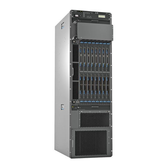
System Overview The PTX5000 occupies 36 rack units (36 U) and accommodates up to eight Flexible PIC Concentrators (FPCs), each of which can be configured with two Physical Interface Cards (PICs) to support a variety of network media types. - Page 22 Figure 1 on page 4 Figure 2 on page 5 illustrate the front and rear of a PTX5000 and its components. Figure 1: Front View of the PTX5000 Front-mounting flange FPCs and PICs — — Craft interface ESD point —...
- Page 23 Vertical fan tray and vertical air filter Power supply module door and power supply — — modules air filter Figure 2: Rear View of the PTX5000 Center-mounting bracket Control Board CB1 and Routing Engine RE1 — — Air exhaust ESD point —...
-
Page 24: Ptx5000 System Architecture Description
— SEE ALSO PTX5000 Chassis Description | 14 Overview of Installing the PTX5000 | 197 PTX5000 System Architecture Description The PTX5000 has two main architectural components: • Routing Engine—One or more Routing Engines provide Layer 3 routing services and network management. -
Page 25: Ptx5000 Hardware Component Overview
The fabric ASICs, located on the Switch Interface Boards (SIBs), extract the route lookup key and manage the flow of data cells across the switch fabric. PTX5000 Hardware Component Overview The PTX5000 supports the components in Table 1 on page 7 listed in alphabetic order. - Page 26 (Continued) Table 1: PTX5000 Hardware Components Component Model Number Hardware Label CLI Output Description FAN3-PTX-H FANTRAY PTX 2 Horizontal Fan HORIZONTAL Tray V3 Air filter kit including FLTR-PTX-KIT – – – the horizontal air filter, vertical air filter, and PSM air filter...
- Page 27 Midplane – – Midplane-8S "PTX5000 Midplane Description" on page Midplane-8SeP See the PTX Series Interface Module Reference "PTX5000 PIC information about the PICs supported on the PTX5000. Description" on page PIC-BLANK-PTX – – – – Three-phase AC delta PDU-PTX-AC-D –...
- Page 28 (Continued) Table 1: PTX5000 Hardware Components Component Model Number Hardware Label CLI Output Description 120-A DC PDU PDU-PTX- – DC Power Dist Unit "PTX5000 DC Power DC-120 System Description" on page 86 60-A DC PDU PDU-PTX-DC-60 – DC PDU 2x60A...
-
Page 29: Ptx5000 Component Redundancy
DOOR-S PTX5000 Component Redundancy The PTX5000 is designed so that no single point of failure can cause the entire system to fail. The following major hardware components are redundant: • Switch Interface Boards (SIBs)—The PTX5000 has nine SIBs. All nine SIBs are active and can sustain full throughput rate. -
Page 30: Ptx5000 Field-Replaceable Units
• Centralized Clock Generators (CCGs)—The PTX5000 has a standard configuration of one CCG. If two CCGs are installed, the second CCG functions as backup. If one CCG fails, the other becomes the primary CCG. Primary Role of the CCG is independent of the host subsystem, so routing functions are not affected. -
Page 31: Ptx5000 Chassis
Before you replace a component in the host subsystem, you must take the host subsystem offline. Table 2 on page 13 lists the FRUs for the PTX5000. Table 2: Field-Replaceable Units Hot-Removable and Hot-Insertable FRUs Hot-Pluggable FRUs • • Air filters SIBs if fewer than eight SIBs are operational •... -
Page 32: Ptx5000 Chassis Description
• Front-mounting flanges for mounting in a four-post rack or cabinet. • Center-mounting metal brackets for center-mounting in an open-frame rack. • Handles on each side to facilitate positioning the PTX5000 in the rack. Do not use the handles to lift the PTX5000. - Page 33 WARNING: The PTX5000 must be connected to earth ground during normal operation. Figure 3: Front View of the PTX5000 Chassis Front-mounting flange FPCs and PICs — — Craft interface ESD point — — Upper horizontal fan tray Lower horizontal fan tray —...
- Page 34 Vertical fan tray and vertical air filter Power supply module door and power — — supply modules air filter Figure 4: Rear View of the PTX5000 Chassis Center-mounting bracket Control Board CB1 and Routing Engine RE1 — — Air exhaust ESD points —...
- Page 35 Chassis grounding points — — Control Board CB0 and Routing Engine RE0 — Figure 5: ESD Points on the PTX5000 SEE ALSO PTX5000 Description | 2 PTX5000 Component Redundancy | 11 PTX5000 Hardware Component Overview | 7 PTX5000 Physical Specifications | 169...
-
Page 36: Ptx5000 Midplane Description
All the cables from one FPC are routed to one channel. The cables are routed from the cable management system to the left side of the PTX5000. The front cable management system adds 3.8 in. (9.7 cm) to the depth of the chassis. -
Page 37: Ptx5000 Craft Interface Description
NOTE: We recommend that you use the cable management system to maintain the cable bend radius. SEE ALSO Maintaining the PTX5000 PIC Cables | 527 PTX5000 Craft Interface Description IN THIS SECTION Craft Interface Front Panel | 20... - Page 38 Craft Interface Front Panel Figure 6 on page 20 shows the craft interface. Figure 6: Craft Interface Alarm relay contacts Alarm LEDs and ACO/LT button — — SIB LEDs M/S CHASSIS NUM configuration switches — — Host Subsystem LEDs Power system LEDs —...
- Page 39 Figure 7 on page Figure 7: LCD in Idle Mode The lines in the display report the following information: • First line—Router name. • Second line—Length of time the PTX5000 has been running, reported in the following form: days + hours : minutes...
- Page 40 • Third and fourth lines—Status messages, which rotate at 2-second intervals. Some conditions, such as removal or insertion of a system component, can interrupt the messages. To add a message that alternates every 2 seconds with the default status messages, use the set chassis display message command.
-
Page 41: Ptx5000 Craft Interface Leds
PTX5000 Craft Interface LEDs IN THIS SECTION Craft Interface Alarm LEDs | 24 Craft Interface SIB LEDs | 24 Craft Interface Host Subsystem LEDs | 25 CCG LEDs | 26 Fan Trays LEDs | 26 Power Distribution Unit LEDs | 27... -
Page 42: Craft Interface Alarm Leds
The LCD display on the craft interface reports the cause of the alarm. A condition that causes an alarm LED to light also activates the corresponding alarm relay contact on the craft interface. Table 3 on page 24 describes the alarm LEDs. Table 3: Alarm LEDs on the PTX5000 Craft Interface Shape Color State... -
Page 43: Craft Interface Host Subsystem Leds
(Continued) Table 4: SIB LEDs on the PTX5000 Craft Interface Label Color State Description – SIB is offline or absent. Green On steadily SIB is in active mode and actively passing traffic. – SIB is either offline or not actively passing traffic. -
Page 44: Ccg Leds
LEDs labeled CCG0 show the status of the CCG in slot CCG0. The LEDs labeled CCG1 show the status of the CCG in slot CCG1. Table 6 on page 26 describes the functions of the CCG LEDs. Table 6: PTX5000 CCG LEDs Label Color State... -
Page 45: Power Distribution Unit Leds
(Continued) Table 7: Fan Tray LEDs on the Craft Interface Color State Description – The fan tray is offline or absent. Power Distribution Unit LEDs One OK LED for each power distribution unit is located on the craft interface below the host subsytem LEDs. - Page 46 Table 9: PSM-LED Mapping PDU Type No of PSMs per PDU Mapping of the PSM LEDs on the Craft Interface and the PSMs PSM 0 LED PSM 1 LED PSM 2 LED PSM 3 LED PSM 0 PSM 1 PSM 2 PSM 3 Existing PDUs: PDU-PTX-DC-120...
-
Page 47: Ptx5000 Centralized Clock Generator Description
The Centralized Clock Generators (CCGs) are installed into the upper rear of the chassis in the slots labeled CCG0 and CCG1. One CCG is shipped as part of the standard PTX5000 configuration, but up to two CCGs can be installed to provide redundancy. -
Page 48: Ptx5000 Centralized Clock Generator Leds
GPS external clock inputs, 5 MHz or 10 MHz. The LEDs for the GPS ports are not supported. SEE ALSO Troubleshooting the PTX5000 Centralized Clock Generators | 571 PTX5000 Centralized Clock Generator LEDs Table 11 on page 30 describes the functions of the CCG LEDs.Table 12 on page 31... - Page 49 There is no loss of signal, no signal is detected. FAULT Yellow On steadily The CCG has detected a failure. – The CCG has not detected a failure or is not powered on. SEE ALSO Troubleshooting the PTX5000 Centralized Clock Generators | 571...
-
Page 50: Ptx5000 Cooling System
Power Supplies | 38 Fan Trays The PTX5000 cooling system components work together to keep all components within the acceptable temperature range. If the maximum temperature specification is exceeded and the system cannot be adequately cooled, the Routing Engine shuts down some or all of the hardware components. If a fan fails or the temperature rises above the temperature thresholds, the speed of the remaining fans in the zone is automatically adjusted to keep the temperature within the acceptable range. - Page 51 interchangeable with the horizontal fan trays. The fans in the Fan Tray 0 are set to a default speed of 21% of maximum speed. Figure 11: Vertical Fan Tray • Cooling zone 1—The upper Fan Tray 1 and lower Fan Tray 2 horizontal fan trays, each of which contain six fans, cool the components installed in the front card cage (FPCs and PICs), and the CCGs.
- Page 52 NOTE: FPCs 3 and 4 can be cooled by either cooling zone 1 section. When FPCs are installed in a section, the software sets the fan speeds according to the temperature. When no FPCs are installed in cooling zone 1 section 1, the left fans in the horizontal fan trays in cooling zone 1 are set to 34% of maximum speed.
- Page 53 Airflow Figure 14 on page 35 shows the airflow through the PTX5000. Figure 14: Airflow Through the Chassis Air Filters The cooling system contains three air filters:...
- Page 54 • One air filter is located inside the vertical fan tray (Figure 15 on page 36). Figure 15: Vertical Fan Tray Air Filter...
- Page 55 • One air filter is located below the lower horizontal fan tray (Figure 16 on page 37). Figure 16: Horizontal Fan Tray Air Filter • One air filter is located inside the door for the power supply modules (Figure 17 on page 37).
-
Page 56: Ptx5000 Ac Power System
PTX5000 Three-Phase Delta AC Power Distribution Unit Specifications | 74 PTX5000 Three-Phase Wye AC Power Distribution Unit Specifications | 74 PTX5000 High Capacity Delta AC Power Distribution Unit Specifications | 75 PTX5000 High Capacity Wye AC Power Distribution Unit Specifications | 76... -
Page 57: Ptx5000 Ac Power System Description
PTX5000 AC Power System Description IN THIS SECTION AC PDUs Supported on the PTX5000 | 39 PTX5000 Normal Capacity Delta and Wye AC PDUs | 40 PTX5000 High Capacity Delta and Wye AC PDU | 47 PTX5000 High Capacity Single-Phase AC PDU | 54... - Page 58 PTX5000 Normal Capacity Delta and Wye AC PDUs Normal Capacity Three-Phase Delta AC PDU Components Each normal-capacity three-phase delta AC PDU has the following components (see Figure 18 on page 42): • A metal retaining bracket located on the lower right to connect the delta AC power cord to the PDU.
- Page 59 NOTE: The PDUs contain no fans, but are cooled by the fans in the power supply modules.
- Page 60 Figure 18: Three-Phase Delta AC PDU Top Installation handle Circuit breaker — — Front installation handle Wiring compartment — — Power OUTPUT switch Wiring compartment door — —...
- Page 61 Air exhaust ventilation Metal retaining bracket — — Each three-phase delta AC PDU weighs approximately 51.2 lb (23.2 kg). Figure 19 on page 43 shows the three-phase delta AC power cord. Figure 19: Three-Phase Delta AC Power Cord Retaining nut Three-phase delta AC power cord —...
- Page 62 • One 32-A circuit breaker. • A power OUTPUT switch provides power to the PSMs. • LEDs to monitor the status of the PDU. • Twenty-one monitored electronic fuses for the fan trays, Control Boards, and FPCs. NOTE: There are no mechanical fuses in the PDU to be replaced. For output voltage, current protection is provided by electronic fuses, hot-swap circuits, or ORing circuit.
- Page 63 NOTE: The PDUs contain no fans, but are cooled by the fans in the power supply modules.
- Page 64 Figure 20: Three-Phase Wye AC PDU Top Installation handle Circuit breaker — — Front installation handle Wiring compartment — — Power OUTPUT switch Wiring compartment door — —...
- Page 65 — — PTX5000 High Capacity Delta and Wye AC PDU The High Capacity AC Delta and Wye AC PDUs support the following features: • Up to eight PSMs are installed for each PDU. Each High Capacity Delta AC PDU requires a 60-A, 100-A, or 150-A feed, and each High Capacity Wye AC PDU requires a 63-A feed.
- Page 66 • Front-to-back airflow direction. • Single output enable or disable switch to switch on or switch off the output of the PDU. • Reverse polarity protection—The PDU or PSMs are not damaged even if the input voltage is reversed for an indefinite period of time. •...
- Page 67 NOTE: The PDUs contain no fans, but are cooled by the fans in the power supply modules. Figure 22: High Capacity Delta AC PDU Top installation handle Input voltage LED — — Front installation handle Wiring compartment — — PDU OK LED Power input cord selection switch —...
- Page 68 AC power cord. The High Capacity Delta AC PDU supports three power cords for 60 A, 100 A, and 150 A. See "Connecting Power to the PTX5000 High Capacity Delta AC PDUs" on page 235 for setting the power cord selection switch.
- Page 69 • A metal retaining bracket located on the lower right to connect the wye AC power cord to the PDU. • A metal wiring compartment that contains the AC input terminal block and ground. The AC terminal block consists of three input terminals labeled L1, L2, and L3, from left to right. The neutral input is labeled N.
- Page 70 NOTE: The PDUs contain no fans, but are cooled by the fans in the power supply modules. Figure 24: High Capacity Wye AC PDU Top installation handle Circuit breaker — — Front installation handle Input voltage LED — — PDU OK LED Wiring compartment —...
- Page 71 ) for the standby position. Air exhaust ventilation Wiring compartment door — — Each High Capacity Wye AC PDU weighs approximately 63.3 lb (28.7 kg). Figure 25 on page 53 shows the power cord for the High Capacity Wye AC PDU. Figure 25: AC Power Cord Retaining nut AC power cord...
- Page 72 PTX5000 High Capacity Single-Phase AC PDU The High Capacity Single-Phase AC PDU supports the following features: • Supports up to eight high-capacity AC PSMs, each PSM requiresone 30-A or 20-A feed. • Slidable input bracket to cover 20-A or 30-A connectionswith an built-in switch to indicate to the system which connectionsare active (20-A or 30-A inputs).
- Page 73 • Hot-pluggable and hot-removable. • No power zoning for PSMs. High Capacity Single-Phase AC PDU Components Figure 26: High Capacity Single-PhaseAC PDU Components PDU OK LED 20-A/30-A Power cord input connectors — — Output-Enable switch PSM LEDs — — Each High Capacity Single-Phase AC PDU has the following components(Figure 26 on page 55): •...
- Page 74 • Single 12V output power for the boards and 36V outputpower for the fan trays. AC PSMs Supported on the PTX5000 The PTX5000 supports the AC power supply modules (PSMs) listed in Table 14 on page NOTE: Ensure that you use AC PSMs of the same model number during normal operation.
- Page 75 PSM or inside the PDU, use caution to ensure that you have an AC PSM before installing it in any high-capacity AC PDU. Figure 27: AC PSM PTX5000 High Capacity AC PSM Figure 28 on page 58 shows the High Capacity AC PSM. These PSMs are smaller than the normal-...
-
Page 76: Ptx5000 Ac Power Distribution Unit Leds
Light load condition occurs when the average input power to the PSMs is less than 422 W. Figure 28: High Capacity AC PSM PTX5000 AC Power Distribution Unit LEDs IN THIS SECTION Three-Phase Delta AC PDU LEDs | 60... - Page 77 High Capacity Delta AC PDU LEDs | 66 High Capacity Wye AC PDU | 68...
- Page 78 Three-Phase Delta AC PDU LEDs Figure 29 on page 61 shows the three-phase delta AC PDU LEDs.
- Page 79 Figure 29: Three-Phase Delta AC PDU LEDs PDU OK LED 200-240 V 60 A 50-60 Hz LED — — CB ON LED — Table 15 on page 62 describes the LEDs on the three-phase delta AC PDU faceplate.
- Page 80 Table 15: Three-Phase Delta AC PDU LEDs Color State Description PDU OK—One per power Green On steadily PDU is functioning normally. supply On steadily PDU has failed. – This LED can be off for one of the following reasons: • The PDU is not receiving any input voltage.
- Page 81 Three-Phase Wye AC PDU LEDs Figure 30 on page 64 shows the three-phase wye AC PDU LEDs.
- Page 82 Figure 30: Three-Phase Wye AC PDU LEDs PDU OK LED 220-240 V/346-415 V 30 A 50-60 Hz LED — — CB ON LED — Table 16 on page 65 describes LEDs on the the three-phase wye AC PDU faceplate.
- Page 83 Table 16: Three-Phase Wye AC PDU LEDs Color State Description PDU OK—One per power Green On steadily PDU is functioning normally. supply On steadily PDU has failed. – This LED can be off for one of the following reasons: • The PDU is not receiving any input voltage.
- Page 84 High Capacity Delta AC PDU LEDs Figure 31 on page 66 shows the High Capacity Delta AC PDU LEDs. Figure 31: High Capacity Delta AC PDU LEDs PDU OK LED AC input (~) LED — — Table 17 on page 66 describes the LEDs on the High Capacity Delta AC PDU faceplate.
- Page 85 (Continued) Table 17: High Capacity Delta AC PDU LEDs Color State Description Blinking A 36 V converter fault has occurred, but the 36 V output remains operational. On steadily PDU has failed. – This LED can be off for one of the following reasons: •...
- Page 86 High Capacity Wye AC PDU Figure 32 on page 68 shows the High Capacity Wye AC PDU LEDs. Figure 32: High Capacity Wye AC PDU LEDs PDU OK LED AC input (~) LED — — CB OK LED — Table 18 on page 68 describes the LEDs on the High Capacity Wye AC PDU faceplate.
- Page 87 (Continued) Table 18: High Capacity Wye AC PDU LEDs Color State Description Blinking A 36 V converter fault has occurred, but the 36 V output remains operational. On steadily PDU has failed. – This LED can be off for one of the following reasons: •...
-
Page 88: Ptx5000 Ac Power Supply Module Leds
PTX5000 AC Power Supply Module LEDs IN THIS SECTION AC Power Supply Module LEDs | 70 High Capacity AC Power Supply Module LEDs | 71 AC Power Supply Module LEDs Figure 33 on page 70 describes the LEDs on the AC power supply module (PSM) faceplate. - Page 89 AC IN OK LED FAULT LED — — DC IN OK LED — Table 19: AC Power Supply Module LEDs Color State Description AC IN OK Green On steadily PSM is receiving voltage. Blinking PSM is receiving voltage outside the supported range. –...
- Page 90 Table 20: High Capacity AC Power Supply Module LEDs Color State Description AC input OK Green On steadily PSM is receiving voltage. Blinking PSM is receiving voltage outside the supported range. The supported range is 180–305 V. – Input voltage is not present. AC outputOK Green On steadily...
-
Page 91: Ptx5000 Ac Power System Specifications
– No faults have been detected for the PSM, or the PSM is not receiving any input voltage. PTX5000 AC Power System Specifications Table 21 on page 73 lists the AC power system electrical specifications. Table 21: AC Power System Electrical Specifications... -
Page 92: Ptx5000 Three-Phase Delta Ac Power Distribution Unit Specifications
PTX5000 Three-Phase Delta AC Power Distribution Unit Specifications Table 22 on page 74 lists the AC power distribution unit (PDU) electrical specifications. Table 22: Three-Phase Delta AC PDU Electrical Specifications Item Specification Maximum output power 17,600 W AC input voltage... -
Page 93: Ptx5000 High Capacity Delta Ac Power Distribution Unit Specifications
25 A @ 240 VAC (line-to-neutral) 30 A @ 200 VAC (line-to-neutral) Maximum AC input 16,600 W PTX5000 High Capacity Delta AC Power Distribution Unit Specifications Table 24 on page 75 lists the High Capacity Delta AC power distribution unit (PDU) electrical specifications. -
Page 94: Ptx5000 High Capacity Wye Ac Power Distribution Unit Specifications
PTX5000 High Capacity Wye AC Power Distribution Unit Specifications Table 25 on page 76 lists the High Capacity Wye AC power distribution unit (PDU) electrical specifications. Table 25: High Capacity Wye AC PDU Electrical Specifications Item Specification Maximum output power... -
Page 95: Ptx5000 Ac Power Cord Specifications
AC input current rating 16-A maximum for 20-A inputs or 24-A maximum for 30-A inputs PTX5000 AC Power Cord Specifications Most sites distribute power through a main conduit that leads to frame-mounted power distribution panels, one of which can be located at the top of the rack that houses the router. An AC power cord connects the power distribution units (PDUs) to the power distribution panel. - Page 96 (Continued) Table 27: AC Power Cord Specifications for the Three-Phase AC Power Cords Power Region Model Number Electrical Plug Type Wire Pole Cord Specification CBL2-PTX-100AC- 100 A @ 250 V CBL2-PTX-150AC- 150 A @ 250 A Europe CBL-PTX-AC-W 32 A @ 400 VAC IEC60309 5 wires labeled 4-pole...
- Page 97 Figure 34 on page 79 Figure 35 on page 80 show the AC power cord provided for each region supported. Figure 34: Three-Phase Delta AC Power Cord...
- Page 98 Retaining nut Three-phase delta AC power cord — — Figure 35: Three-Phase Wye AC Power Cord Retaining nut Three-phase wye AC power cord — —...
- Page 99 Figure 36 on page 81 through Figure 40 on page 83 show the three-phase plugs for each region. Figure 36: Three-Phase Delta 60-A Plug Type (North America) Figure 37: Three-Phase Delta 100-A Plug Type (North America)
- Page 100 Figure 38: Three-Phase Delta 150-A Plug Type (North America) Figure 39: Three-Phase Wye 32-A Plug Type (Europe)
- Page 101 Figure 40: Three-Phase Wye 63-A Plug Type (Europe) WARNING: The router is pluggable type A equipment installed in a restricted-access location. It has a separate protective earthing terminal (sized for UNC 1/4-20 ground lugs) provided on the chassis in addition to the grounding pin of the power supply cord. This separate protective earthing terminal must be permanently connected to earth.
- Page 102 Table 28: AC Power Cord Specifications for the High Capacity Single-Phase AC Power Cords (Continued) Model Number Facility Connection Cable plug specification Description CBL2-PTX-SP-UK BS 1363 (Type G) UK, Right Angle Plug to Straight CBL2-PTX-SP-SA South Africa and BS 546, IS 1293, SABS South Africa/India, Straight Plug India 164-3...
- Page 103 RELATED DOCUMENTATION Understanding Normal-Capacity Power System Power Zones | 182 Calculating PTX5000 Power Consumption | 177 Connecting the PTX5000 to AC Power | 221 Powering the PTX5000 On and Off | 291 Maintaining the PTX5000 AC Power System | 345...
-
Page 104: Ptx5000 Dc Power System
PTX5000 DC Power System Description IN THIS SECTION PTX5000 DC Power Distribution Unit | 86 PTX5000 DC Power Distribution Unit DC PDUs Supported on the PTX5000 The PTX5000 supports the DC power distribution units (PDUs) in Table 29 on page... - Page 105 Table 29: DC PDUs Supported on the PTX5000 Name Model Number First Supported Junos OS Release DC PDU (120-A feeds) PDU-PTX-DC-120 12.1X48 12.3 DC PDU (60-A feeds) PDU-PTX-DC-60 12.1X48R3 12.3 High Capacity DC PDU (60-A feeds) PDU2-PTX-DC 14.1 PTX5000 Normal Capacity DC PDU Normal Capacity 60-A DC PDU Components NOTE: The 60-A DC PDUs do not have circuit breakers.
- Page 106 Figure 43 on page 88 shows the 60-A DC PDU. Each 60-A DC PDU weighs approximately 60 lb (27.2 kg). Figure 43: 60-A DC PDU Metal handle Input power switches — — Power OUTPUT switch Input power trays — — Air exhaust ventilation —...
- Page 107 Each 60-A input power tray weighs 1.6 lb (0.7 kg), not including cables. The input power tray has two inputs, labeled input –2 and input –1. Each input is labeled RTN and –48 V. The input power switch for both inputs in each input power tray is located on the PDU above the input power tray. Figure 44: 60-A DC Input Terminals •...
- Page 108 • Twenty-one monitored electronic fuses for the fan trays, Control Boards, and FPCs. NOTE: There are no mechanical fuses in the PDU to be replaced. For output voltage, current protection is provided by electronic fuses, hot-swap circuits, or ORing circuit. Electronic fuses and hot-swap circuits also provide current limitation.
- Page 109 Figure 45 on page 91 shows the 120-A DC PDU. Each 120-A DC PDU weighs approximately 60 lb (27.2 kg). Figure 45: 120-A DC PDU Metal handle Circuit breakers — — Power switch Input power trays — — Air exhaust ventilation —...
- Page 110 Each 120-A DC PDU has the following components: • Four removable input power trays, labeled 0 through 3, from left to right. The input power trays are hot-removable and hot-insertable. Each 120-A input power tray weighs 1.6 lb (0.7 kg), not including cables. The input power tray has one input, labeled RTN and –48 V, from left to right, and has its own 125-A circuit breaker located on the PDU above the input power tray.
- Page 111 • Front-to-back airflow direction. • Single output enable or disable switch to switch on or switch off the output of the PDU, which enables or disables the outputs from all the PSMs in the PDU. • Reverse polarity protection—The PDU or PSMs are not damaged even if the input voltage is reversed for an indefinite period of time.
- Page 112 Figure 46 on page 94 shows the High Capacity 60-A DC PDU. Each 60-A DC PDU weighs approximately 64.5 lb (29.3 kg). Figure 46: High Capacity DC PDU Metal handle PSM LEDs — — PDU OK LED Input power terminals and safety cover —...
- Page 113 • Four fixed power input terminal blocks stacked vertically. Each terminal has inputs for each PSM—for example, PSM0_1— indicates the first input terminal for PSM0. Each input is also labeled RTN and – 48 V/60A (see Figure 47 on page 95 Figure 48 on page 96).
- Page 114 "PTX5000 DC Power Distribution Unit LEDs" on page 99 for details. • Air exhaust ventilation PTX5000 DC Power Supply Module DC PSMs Supported on the PTX5000 The PTX5000 supports the DC power supply modules (PSMs) in Table 30 on page...
- Page 115 Table 30: DC PSMs Supported on the PTX5000 Name Model Number First Supported Junos OS Release DC PSM (120-A) PSM-PTX-DC-120 12.1X48 12.3 DC PSM (60-A) PSM-PTX-DC-60 12.1X48R3 12.3 High Capacity DC PSM (60-A) PSM2-PTX-DC 14.1 PTX5000 Normal Capacity DC PSM Figure 49 on page 98 shows both the normal-capacity 60-A DC PSM and 120-A DC PSM.
- Page 116 PSM before installing it in the PDU. Figure 49: 60-A DC PSM and 120-A DC PSM PTX5000 High Capacity DC PSM Each High Capacity DC PSM has 3.8 kW output and accepts two 60-A input feeds. These PSMs are smaller than the 60-A DC and 120-A DC PSMs, allowing up to eight PSMs to be installed per PDU, and up to 16 PSMs per chassis.
-
Page 117: Ptx5000 Dc Power Distribution Unit Leds
• I2C fault reporting and control Figure 50 on page 99 shows the High Capacity DC PSM. Figure 50: High Capacity DC PSM PTX5000 DC Power Distribution Unit LEDs IN THIS SECTION 60-A DC PDU LEDs | 100 120-A DC PDU LEDs | 102... - Page 118 60-A DC PDU LEDs Figure 51 on page 100 shows the 60-A DC PDU LEDs. Figure 51: 60-A DC PDU PDU OK LED DC IN LEDs — — SW ON LEDs — Table 31 on page 100 describes the LEDs on the 60-A DC PDU faceplate. Table 31: 60-A DC PDU LEDs Color State...
- Page 119 (Continued) Table 31: 60-A DC PDU LEDs Color State Description On steadily PDU has failed. – PDU might be starting up or not receiving any input voltage. DC IN—One per input Green On steadily Input is receiving voltage. – Input voltage is not present, or is under –40 V. SW ON—One per input Green On steadily...
- Page 120 120-A DC PDU LEDs Figure 52 on page 102 shows the 120-A DC PDU LEDs. Figure 52: 120-A DC PDU LEDs PDU OK LED –48 V 120 A LED — — CB ON LED — Table 32 on page 103 describes the LEDs on the 120-A DC PDU faceplate.
- Page 121 Table 32: 120-A DC PDU LEDs Color State Description PDU OK—One per power Green On steadily PDU is functioning normally. supply On steadily PDU has failed. – PDU might be starting up or not receiving any input voltage. The circuit breakers might be off. –48 V 120 A—One per input Green On steadily...
- Page 122 High Capacity DC PDU LEDs Figure 53 on page 104 shows the High Capacity DC PDU LEDs. Figure 53: High Capacity DC PDU LEDs PDU OK LED PSM_0 through PSM_7 LEDs—There are two — — LEDs—-1 and -2— that indicate the status of the two inputs for each PSM, that is, input -1 and -2.
-
Page 123: Ptx5000 Dc Power Supply Module Leds
–20 V and –43 V. On steadily Connection is reversed. PTX5000 DC Power Supply Module LEDs IN THIS SECTION 60-A and 120-A DC Power Supply Module LEDs | 106 High Capacity DC Power Supply Module LEDs | 108... - Page 124 60-A and 120-A DC Power Supply Module LEDs Table 34 on page 106 describes the DC power supply module LEDs on the faceplate. The 60-A PSM and 120-A PSM have the same LEDs. Figure 54: DC PSM LEDs DC IN OK LED FAULT —...
- Page 125 (Continued) Table 34: DC Power Supply Module LEDs Color State Description Blinking PSM is receiving voltage outside the range of –40 V through – 72 V. – Input voltage is not present. DC OUT OK Green On steadily Output is functioning normally, and input voltage is within the range of the range of –40 V through –72 V.
- Page 126 High Capacity DC Power Supply Module LEDs Figure 55 on page 108 shows the High Capacity DC power supply module LEDs and Table 35 on page describes the LEDs. Figure 55: High Capacity DC PSM LEDs Input 1 OK LED Output OK LED —...
-
Page 127: Ptx5000 Dc Power System Electrical Specifications
– No faults have been detected for the PSM, or the PSM is not receiving any input voltage. PTX5000 DC Power System Electrical Specifications Table 36 on page 110 lists the DC power system electrical specifications. -
Page 128: Ptx5000 Dc Power Distribution Unit Specifications
Operating range: –40.0 to –72.0 VDC DC system current rating 704 A @ –48 VDC (nominal) (30,400 W) For details on circuit breakers, see "PTX5000 AC and DC PDU Electrical and External Circuit Breaker Specifications" on page 166. PTX5000 DC Power Distribution Unit Specifications... -
Page 129: Ptx5000 Dc Power Cable And Lugs Specifications
Input DC current rating 44.2 A @ –48 VDC (nominal) (2120 W) per input To allow for future growth so that you can operate the PTX5000 in any hardware configuration without upgrading the power infrastructure, we recommend that you provision the following: •... - Page 130 ) maximum WARNING: For field-wiring connections, use copper conductors only. WARNING: DC power cables must not block access to PTX5000 components or drape where people could trip on them. CAUTION: Before PTX5000 installation begins, a licensed electrician must attach a cable lug to the power cables that you supply.
- Page 131 DC Power Lugs The accessory box shipped with the PTX5000 includes 0-AWG and 4-AWG cable lugs . The cable lugs are dual hole, and sized to fit 1/4-20 UNC terminal studs at 15.86-mm (0.625-in.) center line. Table 42 on page 113 indicates the cable lug specifications for each type of PDU.
-
Page 132: Ptx5000 Dc Power Distribution
Most sites distribute DC power through a main conduit that leads to frame-mounted DC power distribution panels, one of which might be located at the top of the rack that houses the PTX5000. A pair of cables (one input and one return) connects each set of terminal studs to the power distribution panel. - Page 133 DC source cabling arrangement and two 120-A DC PDUs. The source cabling distribution for 60-A DC PDUs would be similar. Figure 58: Typical DC Source Cabling to the PTX5000 RELATED DOCUMENTATION Understanding Normal-Capacity Power System Power Zones | 182...
-
Page 134: Ptx5000 Host Subsystem
PTX5000 Control Board LEDs | 135 PTX5000 Host Subsystem Description The PTX5000 host subsystem is comprised of a Routing Engine and Control Board working together as a unit. The host subsystem provides the routing and system management functions of the PTX5000. You can install one or two host subsystems. -
Page 135: Ptx5000 Routing Engine Description
Routing Engine Boot Sequence | 122 Routing Engine Slots You can install one or two Routing Engines in the PTX5000. The Routing Engines install into the Control Boards labeled CB0 and CB1. If two Routing Engines are installed, one functions as the primary and the other acts as the backup. -
Page 136: Re-Duo-C2600-16G Routing Engine Components
• Storage and change management—Configuration files, system images, and microcode can be held and maintained in primary and secondary storage systems, permitting local or remote upgrades. • Monitoring efficiency and flexibility—The PTX5000 supports functions such as alarm handling and packet counting on every port, without degrading packet-forwarding performance. - Page 137 • Reset button—Reboots the Routing Engine when pressed. • Offline button—Takes the Routing Engine offline when pressed. • Extractor clips—Control the locking system that secures the Routing Engine. • LEDs—"PTX5000 Routing Engine LEDs" on page 123 describes the functions of these LEDs.
-
Page 138: Re-Ptx-X8-64G Routing Engine Components
NOTE: For specific information about Routing Engine components (for example, the amount of DRAM), issue the show chassis routing-engine command. RE-PTX-X8-64G Routing Engine Components Figure 60: RE-PTX-X8-64G Routing Engine Components Extractor clips RESET button — — LEDs—DISK1, DISK2, and ONLINE USB0 and USB1 ports —... -
Page 139: Re-Ptx-X8-128G Routing Engine Components
• Extractor clips—Control the locking system that secures the Routing Engine. • LEDs—"PTX5000 Routing Engine LEDs" on page 123 describes the functions of these LEDs. NOTE: For specific information about Routing Engine components (for example, the amount of DRAM), issue the show chassis routing-engine command. -
Page 140: Routing Engine Boot Sequence
• Extractor clips—Control the locking system that secures the Routing Engine. • LEDs—"PTX5000 Routing Engine LEDs" on page 123 describes the functions of these LEDs. NOTE: For specific information about Routing Engine components (for example, the amount of DRAM), issue the show chassis routing-engine command. -
Page 141: Ptx5000 Routing Engine Leds
PTX5000 Routing Engine LEDs IN THIS SECTION Routing Engine LEDs (RE-DUO-C2600-16G) | 123 Routing Engine LEDs (RE-PTX-X8-64G and RE-PTX-X8-128G) | 125 Routing Engine LEDs (RE-DUO-C2600-16G) Three LEDs—Online, CF, and Disk1—indicate the status of the Routing Engine (see Figure 62 on page 123). - Page 142 (Continued) Table 43: Routing Engine LEDs Label Color State Description On steadily Routing Engine is not functioning normally. – Routing Engine is not online or not functioning normally. Disk1 Green On steadily An SSD is installed in the Disk1 slot in the Routing Engine. Blinking Indicates disk activity.
- Page 143 Routing Engine LEDs (RE-PTX-X8-64G and RE-PTX-X8-128G) Figure 63: RE-PTX-X8-64G Routing Engine LEDs DISK1 LED ONLINE/OFFLINE button — — DISK2 LED RESET button — — ONLINE LED — Table 44: RE-PTX-X8-64G and RE-PTX-X8-128G Routing Engine LEDs Label Color State Description ONLINE Green On steadily Routing Engine is functioning normally.
-
Page 144: Routing Engines Supported On Ptx Series Routers
IN THIS SECTION PTX1000 Routing Engines | 126 PTX3000 Routing Engines | 126 PTX5000 Routing Engines | 127 PTX10008 and PTX10016 Routing Engines | 128 PTX Series Routing Engine Specifications | 129 The following tables list the Routing Engines that each PTX Series router supports and the Routing Engine specifications. - Page 145 NOTE: • PTX5000 supports 64-bit Junos OS only. • The PTX5000 router supports two midplanes. The midplane identified as Midplane-8S in the CLI output is supported in Junos OS releases, 12.1X48, 12.3, and 13.2. The enhanced midplane, identified as Midplane-8SeP is supported from Junos OS release 14.1 onwards.
- Page 146 Table 47: PTX5000 Routing Engines Model Number Name in CLI Output First Supported Junos OS Management Internal Ethernet Release Ethernet Interface Interface RE-DUO- RE-DUO-2600 12.1X48 ixgbe0 C2600-16G 12.3 ixgbe1 13.2 NOTE: The PTX5000 does not support Junos OS Releases 12.1, 12.2, or 13.1.
- Page 147 Connection to Packet Disk Media Forwarding Engines RE-DUO-C2600-16G 2.6 GHz 16 GB Gigabit Ethernet 4-GB CompactFlash card RE-PTX-X8-64G 2.3 GHz 64 GB 10-Gigabit Ethernet Dual SSD – (PTX5000 only) RE-PTX-X8-128G 2.3 GHz 128 GB 10-Gigabit Ethernet Dual SSD – (PTX5000 only)
- Page 148 (Continued) Table 49: PTX Series Routing Engine Specifications Model Number Processor Memory Connection to Packet Disk Media Forwarding Engines RCB-PTX-X6-32G 2.0 GHz 32 GB 10-Gigabit Ethernet Dual SSD – (PTX3000 only) NOTE: Each link can operate at 10-Gbps or 1-Gbps depending on the capability of the FPC.
-
Page 149: Ptx5000 Control Board Description
Control Board Slots You can install up to two Control Boards in the PTX5000. Control Boards install into the rear of the chassis in the slots labeled CB0 and CB1. A Routing Engine installs directly into a slot on each Control Board. - Page 150 LAN (or any other device that plugs into an Ethernet connection) for management of the PTX5000. The port uses an autosensing RJ-45 connector to support 10- Mbps, 100-Mbps, or 1-Gbps connections. Two small LEDs on the bottom edge of the port indicate the port speed and traffic on the port.
- Page 151 • AUX— One copper 9600 baud port for connecting the Routing Engine to a laptop, modem, or other auxiliary device through a copper cable with RJ-45 connectors. NOTE: If a PTX5000 contains two host subsystems, connect both Control Boards to your external management network.
- Page 152 LAN (or any other device that plugs into an Ethernet connection) for management of the PTX5000. The port uses an autosensing RJ-45 connector to support 10- Mbps, 100-Mbps, or 1-Gbps connections. Two small LEDs on the bottom edge of the port indicate the port speed and traffic on the port.
-
Page 153: Ptx5000 Control Board Leds
NOTE: If a PTX5000 contains two host subsystems, connect both Control Boards to your external management network. • Eighteen 10-Gigabit Ethernet SFP+ fiber-optic ports—labeled (X)GE0 through (X)GE17—located to the right of the management ports. These ports are reserved for future use. However, (X)GE14 and (X)GE15 are configured as 1-Gigabit Ethernet ports. - Page 154 (Continued) Table 50: Control Board CB-PTX LEDs Label Color State Description – Control Board is functioning as the backup. FAIL Yellow On steadily Control Board has failed. – No faults have been detected on the Control Board. Green On steadily Control Board is online and is functioning normally.
- Page 155 (Continued) Table 51: Control Board CB-PTX Port LEDs Port Label Color State Description Green – NOTE: This port is reserved for future use. Figure 67: Control Board CB2-PTX LEDs LCL-MASTER, FAIL, and OK status LEDs Link and activity LEDs for the Gigabit —...
- Page 156 (Continued) Table 52: Control Board CB2-PTX LEDs Label Color State Description – Control Board is offline. MC-MASTERSHIP LEDs MASTER These LEDs are reserved for future use for multichassis applications. STBY Table 53: Control Board CB2-PTX Port LEDs Port Label Color State Description HOST/ETHERNET...
-
Page 157: Ptx5000 Switch Interface Boards
Ethernet ports. RELATED DOCUMENTATION PTX5000 Craft Interface LEDs | 23 Connecting the PTX5000 to a Management Console or Auxiliary Device | 275 Connecting the PTX5000 to a Management Ethernet Device | 276 Maintaining the PTX5000 Host Subsystem | 460 Troubleshooting the PTX5000 Host Subsystem | 605... -
Page 158: Ptx5000 Switch Interface Board Description
SIB Components | 141 SIB Slots The PTX5000 Switch Interface Boards (SIBs) form the switch fabric for the router. Each PTX5000 contains nine SIBs located at the center rear of the chassis in the slots labeled SIB0 through SIB8 (top to bottom). - Page 159 SIB Components Figure 68 on page 141 ,Figure 69 on page 141 , and Figure 70 on page 141 show the supported SIBs. Each SIB weighs 6 lb (2.7 kg). Figure 68: SIB-I-PTX5008 SIB OK, FAIL, and ACTIVE LEDs ONLINE/OFFLINE button —...
-
Page 160: Ptx5000 Switch Interface Board Leds
• Three LEDs located on the SIB faceplate that display the status of the SIB. The OK and ACT LEDs are replicated on the craft interface. PTX5000 Switch Interface Board LEDs Figure 71: SIB LEDs OK, FAIL, and ACTIVE LEDs ONLINE/OFFLINE button —... -
Page 161: Ptx5000 Interface Modules
RELATED DOCUMENTATION Maintaining the PTX5000 Switch Interface Boards | 506 Troubleshooting the PTX5000 Switch Interface Boards | 616 PTX5000 Interface Modules IN THIS SECTION PTX5000 FPC Description | 143 FPCs Supported on the PTX5000 | 147 PTX5000 FPC LEDs | 148... - Page 162 PTX5000. FPC Function FPCs house the PICs that connect the PTX5000 to network media. The main function of an FPC is to connect the PICs installed in it to the other chassis components. The Packet Forwarding Engine receives incoming packets from the PICs installed on the FPC and forwards them through the switch planes to the appropriate destination port.
- Page 163 Identifying the FPCs Check the label on the faceplate to identify the FPC, as shown in Figure 72 on page 145. Figure 72: Identifying the FPCs...
- Page 164 FPC Terminology Regardless of whether you are holding an FPC vertically or horizontally, this document uses the same terms for all four edges of the FPC (see Figure 73 on page 146): • Faceplate—Edge of the FPC that has slots into which you insert the PICs •...
-
Page 165: Fpcs Supported On The Ptx5000
FPCs Supported on the PTX5000 Table 55 on page 147 lists the FPCs supported on the PTX5000. The First Junos OS Release Supported column indicates the first release that the FPC is supported on the PTX5000. NOTE: PTX5000 does not support Junos OS Releases 12.1, 12.2, or 13.1. -
Page 166: Ptx5000 Fpc Leds
IN THIS SECTION PTX5000 PIC Slots | 148 PTX5000 PIC Function | 149 PICs Supported on the PTX5000 | 149 PTX5000 PIC Components | 150 PTX5000 PIC Slots Each FPC has two PIC slots. Blank PICs resemble other PICs but do not provide any physical connection or activity. - Page 167 Before transmitting outgoing data packets, the PICs encapsulate the packets received from the FPCs. PICs Supported on the PTX5000 PICs Supported on the PTX Series for a complete list of PICs supported on the PTX5000.
-
Page 168: Pics Supported On The Ptx Series
PTX5000 PIC Components Figure 74 on page 150 shows an example of a PIC supported on the PTX5000. PICs have an upper ejector handle and a lower ejector handle. Figure 74: PIC Faceplate PICs Supported on the PTX Series Table 57 on page 151 lists the PICs supported on the PTX Series and the first Junos OS release that supports each PIC. - Page 169 PTX Series PIC/FPC Compatibility for information about supported FPC and PIC combinations. NOTE: PTX5000 does not support Junos OS Releases 12.1, 12.2, or 13.1. Table 57: PICs Supported on the PTX Series PIC Family and Type Ports Model Number PIC First Supported...
- Page 170 (Continued) Table 57: PICs Supported on the PTX Series PIC Family and Type Ports Model Number PIC First Supported PIC First Supported on PTX3000 on PTX5000 10-Gigabit Ethernet/40-Gigabit Ethernet/100-Gigabit Ethernet 10-Port 10-Gigabit Ethernet, P3-10-U-QSFP28 16.1R3 17.1R1 40-Gigabit Ethernet, 100- 17.1R1...
-
Page 171: Ptx Series Pic/Fpc Compatibility
PICs supported on each PTX Series router, the FPCs that support each PIC, and the first Junos OS release that supports each PIC and FPC combination. NOTE: PTX5000 does not support Junos OS Releases 12.1, 12.2, or 13.1. PTX3000 PIC/FPC Compatibility Table 58 on page 154... - Page 172 Table 58: PTX3000 PIC/FPC Compatibility PIC Family and Type Model Number PIC First PIC First PIC First Supported Supported on Supported on on FPC3-SFF-PTX FPC-SFF-PTX- FPC-SFF-PTX-T 10-Gigabit Ethernet 10-Gigabit Ethernet PIC P1-PTX-24-10GE- 13.2R2 14.1R1 Not supported with SFP+ (PTX Series) SFPP 10-Gigabit Ethernet P1-PTX-24-10G-W-...
- Page 173 100-Gigabit DWDM P1-PTX-2-100G- 13.3R1 14.1R1 Not supported OTN PIC (PTX Series) 100-Gigabit DWDM PTX-5-100G-WDM Not supported Not supported 15.1F6 OTN PIC with CFP2- 17.1R1 ACO (PTX Series) PTX5000 PIC/FPC Compatibility Table 59 on page 156 describes PIC/FPC compatibility for the PTX5000.
- Page 174 Table 59: PTX5000 PIC/FPC Compatibility PIC Family and Model Number PIC First PIC First PIC First PIC First Type Supported on Supported on Supported on Supported on FPC-PTX-P1-A FPC2-PTX- FPC3-PTX-U2 FPC3-PTX-U3 10-Gigabit Ethernet 10-Gigabit Ethernet P1-PTX-24-10GE- 12.1X48 14.1R1 Not supported...
- Page 175 (Continued) Table 59: PTX5000 PIC/FPC Compatibility PIC Family and Model Number PIC First PIC First PIC First PIC First Type Supported on Supported on Supported on Supported on FPC-PTX-P1-A FPC2-PTX- FPC3-PTX-U2 FPC3-PTX-U3 10-Gigabit Ethernet/40-Gigabit Ethernet/100-Gigabit Ethernet 10-Port 10-Gigabit P3-10-U-QSFP28 Not supported 17.1R1...
- Page 176 (PTX Series) 100-Gigabit PTX-5-100G- Not supported 15.1F6 15.1F6 DWDM OTN PIC supported 17.1R1 17.1R1 with CFP2-ACO (PTX Series) RELATED DOCUMENTATION Maintaining PTX5000 Interface Modules | 509 Troubleshooting the PTX5000 FPCs | 620 Troubleshooting the PTX5000 PICs and PIC Transceivers | 625...
-
Page 177: Site Planning, Preparation, And Specifications
C HAPTER Site Planning, Preparation, and Specifications Overview of Preparing the Site for the PTX5000 | 160 PTX5000 Site Guidelines and Requirements | 162 PTX5000 Power Planning | 177 Network Cable and Transceiver Planning | 187 PTX5000 Alarm and Management Cable Specifications and Pinouts | 192... -
Page 178: Overview Of Preparing The Site For The Ptx5000
Overview of Preparing the Site for the PTX5000 To prepare a site for PTX5000 installation: Verify that environmental factors such as temperature and humidity do not exceed PTX5000 tolerances. "PTX5000 Environmental Specifications" on page 162. Verify that the site and installation plan meets all safety guidelines and requirements. - Page 179 Verify that the plan for power installation meets all electrical safety guidelines. Site Electrical Wiring Guidelines General Electrical Safety Guidelines and Warnings Verify that your rack meets the minimum requirements for the installation of the PTX5000. • "Rack Requirements for the PTX5000" on page 174 •...
-
Page 180: Ptx5000 Site Guidelines And Requirements
General Site Guidelines | 163 PTX5000 Chassis Grounding Cable and Lug Specifications | 164 PTX5000 AC and DC PDU Electrical and External Circuit Breaker Specifications | 166 PTX5000 Clearance Requirements for Airflow and Hardware Maintenance | 168 PTX5000 Physical Specifications | 169... -
Page 181: General Site Guidelines
• High-capacity AC and DC power: 115,182 BTU/hour (33,778 W) NOTE: Install the PTX5000 only in restricted areas, such as dedicated equipment rooms and equipment closets, in accordance with Articles 110-16, 110-17, and 110-18 of the National Electrical Code, ANSI/NFPA 70. -
Page 182: Ptx5000 Chassis Grounding Cable And Lug Specifications
A cable with an incorrectly attached lug can damage the PTX5000. NOTE: You must install the PTX5000 in a restricted-access location and ensure that the chassis is always properly grounded. The PTX5000 has a two-hole protective grounding terminal provided on the chassis. - Page 183 along with the two-hole grounding lug connection. This tested system meets or exceeds all applicable EMC regulatory requirements with the two-hole protective grounding terminal. Figure 75: 0-AWG Grounding Cable Lug Figure 76: 4-AWG Grounding Cable Lug You must supply a grounding cable. Table 61 on page 165 summarizes the specifications for the grounding cable and lug.
-
Page 184: Ptx5000 Ac And Dc Pdu Electrical And External Circuit Breaker Specifications
PTX5000 AC and DC PDU Electrical and External Circuit Breaker Specifications Table 62 on page 166 lists the AC PDU electrical and external circuit breaker specifications. Table 62: PTX5000 AC PDU Electrical and External Circuit Breaker Specifications Maximum Cable External... - Page 185 (Continued) Table 62: PTX5000 AC PDU Electrical and External Circuit Breaker Specifications Maximum Cable External Operational Feeds Plug Current Circuit Voltage per PDU Rating Drawn Rating Breaker/ Fuse High Capacity Delta AC 114 A 120 A 120 A 200 V–240 V...
-
Page 186: Ptx5000 Clearance Requirements For Airflow And Hardware Maintenance
At least 24 in. (61.0 cm) are required both in front of and behind the PTX5000. NEBS GR-63 recommends that you allow at least 30 in. (72.6 cm) behind the rack. • Additional clearance is required to accommodate the depth of the following components: •... -
Page 187: Ptx5000 Physical Specifications
SEE ALSO PTX5000 Installation Safety Guidelines | 198 PTX5000 Cooling System | 32 PTX5000 Physical Specifications Table 64 on page 169 lists the physical specifications for the PTX5000 chassis and components. Table 64: Physical Specifications Description Weight Height Width Depth... - Page 188 (Continued) Table 64: Physical Specifications Description Weight Height Width Depth Vertical air filter tray 7.6 lb (3.5 kg) 26.4 in. (67 cm) 3.4 in. (8.7 cm) 11.3 in. (28.6 cm) (including the air filter) Control Board CB-PTX: 10 lb (4.5 kg) 3.4 in.
- Page 189 (Continued) Table 64: Physical Specifications Description Weight Height Width Depth P1-PTX-2-40GE-CFP: 3.5 lb (1.6 kg) P2-10G-40G-QSFPP: 4.3 lb (2 kg) P3-15-U-QSFP28: 4 lb (1.8 kg) P3-24-U-QSFP28: 4.3 lb (2 kg) P1-PTX-2-100GE-CFP: 3.5 lb (1.6 kg) P2-100GE-CFP2: 3.9 lb (1.8 kg) P2-100GE-OTN: 4.4 lb (2 kg) P1-PTX-2-100G-WDM:...
- Page 190 (Continued) Table 64: Physical Specifications Description Weight Height Width Depth PDU2-PTX-AC-W: 63.3 lb (28.7 kg) PDU2-PTX-AC-SP: 60.5 lb (27.4 kg) AC PSM 10.5 lb (4.8 kg) 5.7 in. (14.5 cm) 3.4 in. (8.7 cm) 14.1 in. (35.9 cm) DC PDU PDU-PTX-DC-120: 60 lb 18.5 in.
-
Page 191: Site Electrical Wiring Guidelines
SEE ALSO PTX5000 Installation Safety Guidelines | 198 Site Electrical Wiring Guidelines Table 65 on page 173 describes the factors you must consider while planning the electrical wiring at your site. WARNING: You must provide a properly grounded and shielded environment and use electrical surge-suppression devices. -
Page 192: Rack Requirements For The Ptx5000
Connection to Building Structure | 176 Rack Size and Strength The PTX5000 is designed for installation in a rack that complies with either of the following standards: Cabinets, Racks, Panels, and Associated Equipment (document number • A 19-in. rack as defined in... - Page 193 Electronics Industry Association. You can install one chassis in a rack that has at least 35.7 U of usable vertical space. The rack must be strong enough to support the weight of the fully configured PTX5000, up to about 1,200 lb (544.3 kg).
- Page 194 The holes in the mounting brackets and front-mount flanges used to attach the chassis to a rack are spaced at 3 U (5.25 in. or 13.3 cm). The PTX5000 can be mounted in any rack that provides holes spaced at those distances.
-
Page 195: Ptx5000 Power Planning
Use the information in this topic to determine the power consumption for your router. NOTE: Starting in Junos OS Release 14.1, new power management features in Junos OS for PTX5000 ensure that the chassis power requirements do not exceed the power available to the PTX5000. -
Page 196: Power Requirements For Ptx5000 Components
Power Requirements for PTX5000 Components Table 1 describes the output power requirements for the required and optional FRUs for the PTX5000. The power requirements vary depending on the ambient air temperature for your installation. NOTE: The power requirements listed below are accurate for estimating typical power consumption at different ambient temperatures. - Page 197 (Continued) Table 66: Power Requirements for PTX5000 Components Component 25° C (77° F) Ambient 40° C (104° F) Ambient Temperature Temperature SIB-I-PTX5008 SIBs (total power requirements for 9 380 W 450 W SIBs) SIB2-I-PTX5K SIBs (total power requirements for 9...
-
Page 198: Calculating Power Consumption For Your Configuration
• Any FPCs or PICs specific to your configuration 3. Determine the power consumption in watts by dividing the total output power requirements by the power efficiency: • PTX5000 AC and DC normal-capacity power supply module (PSM) efficiency is approximately 88% at full load and nominal voltage. - Page 199 • PTX5000 AC and DC high capacity PSM efficiency is approximately 90% at full load and nominal voltage. The examples below show the power requirement calculations for different types of configurations: NOTE: All the examples below use RE-PTX-X8-64G Routing Engines, CB2-PTX Control Boards, FAN3-PTX-H horizontal fan trays, and SIB3-PTX5K SIBs.
-
Page 200: Calculating System Thermal Output
Power consumption in watts * 3.41 = system thermal output in BTU/hr 13220 W * 3.41 = 45080.2 BTU/hr RELATED DOCUMENTATION PTX5000 AC Power System Specifications | 73 PTX5000 DC Power System Electrical Specifications | 109 Understanding Normal-Capacity Power System Power Zones IN THIS SECTION PSM Slots | 183... - Page 201 NOTE: There is no power zoning in the High Capacity power system. The PTX5000 normal-capacity power system has up to eight power supply modules (PSMs), located in the lower front of the chassis below the FPC card cage. The PSMs insert into one of four slots—labeled 0 through 3—located in the rear of each PDU labeled PDU0 and PDU1.
- Page 202 If neither PSM in this zone is powered on, the fan trays are not powered on, zone is not powered on, the fan and the PTX5000 will not be powered on. trays are not powered on, and the PTX5000 will not be powered on.
- Page 203 Table 69: Power Zone 1 Fault Tolerance Nonredundant Configuration Redundant Configuration PDU0 PDU1 One PSM1 in either PDU can PSM1 in PDU0 is required for full PSM1 in PDU1 is required for full provide power to the craft power redundancy. power redundancy.
- Page 204 If all four PSMs in this zone fail, all FPCs are powered off. SEE ALSO PTX5000 Hardware Component Overview | 7 PTX5000 AC Power Distribution Unit LEDs | 58 PTX5000 DC Power Distribution Unit LEDs | 99 PTX5000 AC Power Supply Module LEDs | 70...
-
Page 205: Network Cable And Transceiver Planning
Juniper Networks. If you face a problem running a Juniper device that uses third-party optical modules or cables, JTAC may help you diagnose host-related issues if the observed issue is not, in the opinion of JTAC, related to the use of the third-party optical modules or cables. -
Page 206: Fiber-Optic Cable Signal Loss, Attenuation, And Dispersion
ZR or ZR+) can potentially cause thermal damage to or reduce the lifespan of the host equipment. Any damage to the host equipment due to the use of third-party optical modules or cables is the users’ responsibility. Juniper Networks will accept no liability for any damage caused due to such use. - Page 207 Single-mode fiber is so small in diameter that rays of light can reflect internally through one layer only. Interfaces with single-mode optics use lasers as light sources. Lasers generate a single wavelength of light, which travels in a straight line through the single-mode fiber. Compared with multimode fiber, single-mode fiber has higher bandwidth and can carry signals for longer distances.
-
Page 208: Calculating Power Budget And Power Margin For Fiber-Optic Cables
TIP: You can use the Hardware Compatibility Tool to find information about the pluggable transceivers supported on your Juniper Networks device. To calculate the power budget and power margin, perform the following tasks: How to Calculate Power Budget for Fiber-Optic Cables To ensure that fiber-optic connections have sufficient power for correct operation, you need to calculate the link's power budget, which is the maximum amount of power it can transmit. - Page 209 – LL greater than zero indicates that the power budget is sufficient to operate the receiver. Factors that can cause link loss include higher-order mode losses, modal and chromatic dispersion, connectors, splices, and fiber attenuation. Table 71 on page 191 lists an estimated amount of loss for the factors used in the following sample calculations.
-
Page 210: Ptx5000 Alarm And Management Cable Specifications And Pinouts
RJ-45 Connector Pinouts for the PTX5000 Management HOST/ETHERNET Port | 195 PTX5000 Alarm Relay Contact Wire Specifications For management and service operations, you can connect the PTX5000 to external alarm-reporting devices through the alarm relay contacts on the craft interface. You must provide a wire with gauge... -
Page 211: Ptx5000 Management Interface Cable Specifications
Port is reserved for future None 328 ft (100 m) use. SEE ALSO PTX5000 Control Board Description | 131 Connecting the PTX5000 to a Management Console or Auxiliary Device | 275 Connecting the PTX5000 to a Management Ethernet Device | 276... -
Page 212: Rj-45 Connector Pinouts For The Ptx5000 Auxiliary And Console Ports
CONSOLE port connects it to a management console. The ports are configured as data terminal equipment (DTE). Table 73 on page 194 describes the RJ-45 connector pinouts. Table 73: RJ-45 Connector Pinouts for the PTX5000 Auxiliary and Console Ports Signal Description RTS Output Request to send... -
Page 213: Connector Pinouts For The Ptx5000 Management Host/Ethernet Port
RJ-45 connector pinouts. Table 74: RJ-45 Connector Pinouts Signal TX – Termination network Termination network RX– Termination network Termination network SEE ALSO PTX5000 Control Board Description | 131 Connecting the PTX5000 to a Management Ethernet Device | 276... -
Page 214: Initial Installation And Configuration
Connecting the PTX5000 to DC Power | 255 Connecting the PTX5000 to External Devices | 274 Installing the Front Doors on the PTX5000 | 283 Powering the PTX5000 On and Off | 291 Performing the Initial Software Configuration for the PTX5000 | 303... -
Page 215: Ptx5000 Installation Overview
160. 2. Review all safety guidelines and warnings for the PTX5000. WARNING: To avoid harm to yourself or the PTX5000 as you install and maintain it, you must follow the safety procedures for working with routers, as well as the guidelines and warnings for working with and near electrical equipment. -
Page 216: Ptx5000 Installation Safety Guidelines
• 60-A DC PDU and PSM—See "Connecting Power to the PTX5000 60-A DC Input Power Trays" on page 262 "Powering On the DC Powered PTX5000 with 60-A DC PDUs and 60-A DC PSMs" on page 294. • 120-A DC PDU and PSM—See "Connecting Power to the PTX5000 120-A DC Input Power Trays"... - Page 217 "Calculating PTX5000 Power Consumption" on page 177 Chassis Lifting Guidelines The weight of a fully configured PTX5000 chassis is 1,200 lb (544.3 kg). Observe the following guidelines for lifting and moving the PTX5000: • A mechanical lift is required to maneuver the PTX5000 into a rack.
-
Page 218: Unpacking The Ptx5000
1. Gather the tools required to unpack the PTX5000. "Tools and Parts Required to Unpack the PTX5000" on page 200. 2. Remove the PTX5000, accessory box, tool kit, and all parts from the shipping crate. "Unpacking the PTX5000" on page 201. -
Page 219: Unpacking The Ptx5000
Unpacking the PTX5000 The PTX5000 is shipped in a wooden crate. A wooden pallet forms the base of the crate. The chassis is bolted to this pallet. Quick Start installation instructions and a cardboard accessory box are also included in the shipping crate. - Page 220 12. Save the shipping crate cover, pallet, and packing materials in case you need to move or ship the PTX5000 at a later time. Figure 79: Contents of the Shipping Crate Shipping crate cover Shipping crate base — — Chassis...
-
Page 221: Verifying The Ptx5000 Parts Received
Verifying the PTX5000 Parts Received A packing list is included in each shipment. The packing list specifies the part numbers and descriptions of each part in your order. To verify that you have received all parts: 1. Verify that the items on the packing list are included in the parts in the main shipment. - Page 222 (Continued) Table 75: PTX5000 Parts List Component Quantity Horizontal fan trays Vertical fan tray Quick start installation Open-frame mounting shelf Four-post mounting shelf Rear support bracket—Required only for mounting a four-post rack or cabinet Blank panels for slots without components installed...
- Page 223 NOTE: Spare cable lugs are included in the accessory kit. Use one of the included spare cable lugs to connect the PTX5000 to earth ground. Connectors for alarm relay cables, Terminal Block Plug, 3 Pole, 5.08 mm spacing, 12 A...
-
Page 224: Installing The Ptx5000 In A Rack
Installing the PTX5000 in a Rack IN THIS SECTION Installing the PTX5000 Mounting Hardware for a Four-Post Rack or Cabinet | 206 Installing the PTX5000 Mounting Hardware for an Open-Frame Rack | 211 Overview of Installing a PTX5000 Using a Mechanical Lift | 213... - Page 225 0.86 U 0.88 in. (2.2 cm) 0.50 U 0.25 in. (0.6 cm) 0.14 U Table 78: Mounting Hole Locations for Installing a PTX5000 in a Four-Post Rack Hole Distance Above U Division 63.88 in. (162.2 cm) 36.50 U 58.63 in. (148.9 cm) 33.50 U...
-
Page 226: Installing The Four-Post Mounting Shelf And Rear Support Bracket
(Continued) Table 78: Mounting Hole Locations for Installing a PTX5000 in a Four-Post Rack Hole Distance Above U Division 32.38 in. (82.2 cm) 18.50 U 27.13 in. (68.9 cm) 15.50 U 21.88 in. (55.6 cm) 12.50 U 16.63 in. (42.2 cm) 9.50 U... -
Page 227: Removing The Center-Mounting Brackets
NOTE: Several holes are provided on top of the shelf. Two holes on each side of the shelf will align with the holes in the rear support bracket. 10. Tighten all the screws completely. Figure 80: Installing the Mounting Hardware for a Four-Post Rack Rear support bracket Four-post mounting shelf —... - Page 228 2. Remove each bracket. Figure 81: Removing the Center-Mounting Bracket...
-
Page 229: Installing The Ptx5000 Mounting Hardware For An Open-Frame Rack
2. On the front side of both rack rails, insert cage nuts in the holes specified for mounting the chassis (see Table Table 79: Mounting Hole Locations for Installing a PTX5000 Open-Frame Rack Shelf Hole Distance Above U Division 17.25 in. (43.8 cm) 9.86 U... -
Page 230: Installing The Open-Frame Rack Mounting Shelf
Table 80: Mounting Hole Locations for Installing a Chassis in an Open-Frame Rack Hole Distance Above U Division 60.38 in. (153.4 cm) 34.50 U 55.13 in. (140.0 cm) 31.50 U 49.88 in. (126.7 cm) 28.50 U 44.63 in. (113.3 cm) 25.50 U 39.38 in. -
Page 231: Overview Of Installing A Ptx5000 Using A Mechanical Lift
Figure 82: Installing the Mounting Hardware for an Open-Frame Rack Overview of Installing a PTX5000 Using a Mechanical Lift Before installing the PTX5000 using a mechanical lift, verify that you have prepared your site, unpacked the chassis from the shipping crate, and installed the mounting hardware. -
Page 232: Tools Required To Install The Ptx5000 Using A Mechanical Lift
Because of the PTX5000 router’s size and weight—up to 1,200 lb (544.3 kg) depending on the configuration— you must install the PTX5000 using a mechanical lift. To install the PTX5000: 1. Gather the tools required to install the PTX5000. "Tools Required to Install the PTX5000 Using a Mechanical Lift" on page 214. - Page 233 Use these handles only to help position the PTX5000. 2. Using the lift, position the PTX5000 in front of the rack, centering it in front of the mounting shelf. 3. Lift the chassis slightly above the surface of the mounting shelf, and position it as close as possible to the shelf.
- Page 234 8. Move the lift away from the rack.
- Page 235 Figure 83: Loading the PTX5000 onto the Lift...
- Page 236 The holes in the center-mounting brackets are spaced at 3 U (5.25 in. or 13.3 cm). Figure 84: Installing the PTX5000 in an Open-Frame Rack Open-frame rack Center-mounting bracket — —...
- Page 237 The holes in the front-mounting flanges are spaced at 3 U (5.25 in. or 13.3 cm). Figure 85: Installing the PTX5000 in a Four-Post Rack Four-post rack Front-mounting flange — — RELATED DOCUMENTATION Rack Requirements for the PTX5000 | 174...
-
Page 238: Connecting The Ptx5000 Grounding Cable
Verifying the PTX5000 Parts Received | 203 Connecting the PTX5000 to Earth Ground You ground the PTX5000 by attaching a grounding cable to the chassis. You must provide the grounding cable. Depending on your configuration, 0-AWG or 4-AWG (21.2 mm ) cable lugs are supplied with DC PDUs, and can be used for grounding. -
Page 239: Connecting The Ptx5000 To Ac Power
221): 1. Connect the grounding cable to a proper earth ground. 2. Verify that a licensed electrician has attached the cable lug provided with the PTX5000 to the grounding cable. 3. Make sure that grounding surfaces are clean and brought to a bright finish before grounding connections are made. -
Page 240: Tools And Parts Required To Provide Ac Power To The Ptx5000
Tools and Parts Required to Provide AC Power to the PTX5000 If you have an AC-powered router, gather the tools required to connect the PTX5000 to AC power: • AC power cords • Phillips (+) screwdriver, number 2 to access the metal AC wiring compartment and remove or attach the AC power cord. - Page 241 Using a number 2 Phillips (+) screwdriver, remove the four screws from the metal retaining bracket located on the lower right of the PDU. Remove the metal retaining bracket from the PDU (see Figure 87 on page 223). Figure 87: Removing the Metal Retaining Bracket from a Three-Phase Delta AC PDU...
- Page 242 Unscrew the retaining nut from the AC power cord (see Figure 88 on page 224 Figure 89 on page 225). Figure 88: Retaining Nut on a Three-Phase Delta AC Power Cord...
- Page 243 Retaining nut Three-phase delta AC power cord — — Figure 89: Removing the Retaining Nut from a Three-Phase Delta AC Power Cord Retaining nut Three-phase delta AC power cord — — Put the wires of the AC power cord through the hole of the metal retaining bracket, and screw the retaining nut onto the AC power cord to secure it to the metal retaining bracket (see Figure 90 on page...
- Page 244 metal AC wiring compartment. Using a number 2 Phillips (+) screwdriver, use the four screws on the metal retaining bracket to secure the AC power cord to the PDU (see Figure 91 on page 226). Figure 91: Connecting Power to a Three-Phase Delta AC PDU Connect the wires to the AC terminal block on the three-phase delta AC PDU (Figure 92 on page 227).
- Page 245 AC wiring compartment. 10. Verify that the AC power cord does not touch or block access to PTX5000 components, and that it does not drape where people could trip on it.
- Page 246 11. Repeat the procedure for the other three-phase delta AC PDU. Figure 93: Three-Phase Delta AC PDU Top installation handle Circuit breaker — —...
-
Page 247: Connecting Power To The Ptx5000 Three-Phase Wye Ac Pdus
Air exhaust ventilation Metal retaining bracket — — Connecting Power to the PTX5000 Three-Phase Wye AC PDUs To connect an AC power cord to a three-phase wye AC PDU (see Figure 100 on page 234): Switch off the customer-site circuit breakers. Ensure that the voltage across the AC power source is 0 V and that there is no chance that the voltage might become active during installation. - Page 248 Unscrew the retaining nut from the AC power cord (see Figure 95 on page 230 Figure 96 on page 231). Figure 95: Retaining Nut on a Three-Phase Wye AC Power Cord...
- Page 249 Retaining nut Three-phase wye AC power cord — — Figure 96: Removing the Retaining Nut from a Three-Phase Wye AC Power Cord Retaining nut Three-phase wye AC power cord — — Put the wires of the AC power cord through the hole of the metal retaining bracket, and screw the retaining nut onto the AC power cord to secure it to the metal retaining bracket (see Figure 97 on page...
- Page 250 screws on the metal retaining bracket to secure the AC power cord to the PDU (see Figure 98 on page 232). Figure 98: Connecting Power to a Three-Phase Wye AC PDU Connect the wires to the AC terminal block on the three-phase wye AC power supply (Figure 99 on page 233).
- Page 251 CAUTION: To avoid damage to the PDU, do not connect the neutral wire to the L1, L2, or L3 input terminals. Figure 99: Connecting Power to the Three-Phase Wye AC Power Supply Verify that the AC power wiring connections are correct. Close the door to the metal AC wiring compartment, and use a number 2 Phillips (+) screwdriver to tighten the two captive screws to secure the door to the metal AC wiring compartment.
- Page 252 11. Repeat the procedure for the other three-phase wye AC PDU. Figure 100: Three-Phase Wye AC PDU Top installation handle Circuit breaker — —...
-
Page 253: Connecting Power To The Ptx5000 High Capacity Delta Ac Pdus
Air exhaust ventilation Metal retaining bracket — — Connecting Power to the PTX5000 High Capacity Delta AC PDUs To connect an AC power cord to a High Capacity Delta AC PDU (see Figure 101 on page 235): Figure 101: High Capacity Delta AC PDU... - Page 254 Top installation handle Input voltage LED — — Front installation handle Wiring compartment — — PDU OK LED Power input cord selection switch — — Power switch labeled (|) for the on position Metal retaining bracket — — ) for the standby position. Air exhaust ventilation Wiring compartment door —...
- Page 255 Unscrew the retaining nut from the AC power cord (see Figure 103 on page 237 Figure 104 on page 238). Figure 103: Retaining Nut on an AC Power Cord Retaining nut AC power cord — —...
- Page 256 NOTE: This is a representational image. The High Capacity Delta AC PDU supports three power cords for 60 A, 100 A, and 150 A, respectively. Figure 104: Removing the Retaining Nut from an AC Power Cord Retaining nut AC power cord —...
- Page 257 Put the wires of the AC power cord through the hole of the metal retaining bracket, and screw the retaining nut onto the AC power cord to secure it to the metal retaining bracket (see Figure 105 on page 239). Figure 105: Connecting the Metal Retaining Bracket to an AC Power Cord NOTE: If you are using 150 A power, you must use a metal bracket that is larger than the default metal bracket.
- Page 258 bracket (see Figure 106 on page 240). The installation procedure to connect the metal bracket to the PDU is the same for both metal brackets. Figure 106: Metal Brackets for Power Cords Metal Bracket with label Use for Metal Bracket with label Use for —...
- Page 259 d. Using a number 2 Phillips (+) screwdriver, use the four screws on the metal retaining bracket to secure the AC power cord to the PDU (see Figure 107 on page 241). Figure 107: Attaching the Power Cord to the High Capacity Delta AC PDU Connect the wires to the AC terminal block on the High Capacity Delta AC PDU (Figure 108 on page...
- Page 260 AC wiring compartment. 10. Verify that the AC power cord does not touch or block access to PTX5000 components, and that it does not drape where people could trip on it.
- Page 261 show chassis environment pdu 0 PDU 0 status: State Online BoostConv OK Feed Switch 150Amps <<<=== Hours Used 142 Firmware Version (MCU1) 03.04 Figure 109: Ampere Switch WARNING: If you set the ampere switch in the wiring compartment incorrectly, the AC power cord might overheat.
-
Page 262: Connecting Power To The Ptx5000 High Capacity Wye Ac Pdus
Connecting Power to the PTX5000 High Capacity Wye AC PDUs To connect an AC power cord to a High Capacity Wye AC PDU (see Figure 110 on page 244): Figure 110: High Capacity Wye AC PDU Top Installation handle Circuit breaker —... - Page 263 ) for the standby position. Air exhaust ventilation Wiring compartment door — — To connect an AC power cord to a High Capacity Wye AC PDU (see Figure 110 on page 244): Switch off the customer-site circuit breakers. Ensure that the voltage across the AC power source is 0 V and that there is no chance that the voltage might become active during installation.
- Page 264 Unscrew the retaining nut from the AC power cord (see Figure 112 on page 246 Figure 113 on page 247). Figure 112: Retaining Nut on an AC Power Cord...
- Page 265 Retaining nut AC power cord — — Figure 113: Removing the Retaining Nut from an AC Power Cord Retaining nut AC power cord — — Put the wires of the AC power cord through the hole of the metal retaining bracket, and screw the retaining nut onto the AC power cord to secure it to the metal retaining bracket (see Figure 114 on page...
- Page 266 c. Push the wires of the AC power cord into the area for the metal retaining bracket, and pull the wires to the left toward the metal AC wiring compartment. d. Using a number 2 Phillips (+) screwdriver, use the four captive screws on the metal retaining bracket to secure the AC power cord to the PDU (see Figure 115 on page 248).
-
Page 267: Connecting Power To The Ptx5000 High Capacity Single-Phase Ac Pdus
AC wiring compartment. 11. Verify that the AC power cord does not touch or block access to PTX5000 components, and that it does not drape where people could trip on it. - Page 268 To connect the AC power cords to the single-phase AC PDUs (see Figure 117 on page 250): Figure 117: Connecting the Source Power to a High Capacity Single-Phase AC PDU 1. Switch off the customer-site circuit breakers. Ensure that the voltage across the AC power source is 0 V and that there is no chance that the voltage might become active during installation.
- Page 269 NOTE: The 30-A connector does not have a clamp, but it has its own integral clip for locking the connector. Figure 118: Plug Type for the 20-A Connector...
- Page 270 Figure 119: Connecting 20-A Inputs to a High Capacity Single-Phase AC PDU...
- Page 271 5. Connect up to eight inputs (20-A or 30-A) to the PDU. See Figure 120 on page 253 Figure 121 on page 254. Figure 120: Plug Types for the 30-A Connector...
- Page 272 Figure 121: Connecting 30-A Inputs to a High Capacity Single-Phase AC PDU 6. Verify that the AC power wiring connections are correct.
-
Page 273: Connecting The Ptx5000 To Dc Power
7. Verify that the AC power cord does not touch or block access to PTX5000 components, and that it does not drape where people could trip on it. 8. Repeat the procedure for the other single-phase AC PDU. RELATED DOCUMENTATION... -
Page 274: Installing The Ptx5000 Cable Management System For A High Capacity Dc Pdu
• Phillips (+) screwdriver, number 2 • DC power cables, which you must provide • DC power lugs Installing the PTX5000 Cable Management System for a High Capacity DC PDU IN THIS SECTION Identifying the Parts of the Cable Management System | 256... -
Page 275: Installing The Cable Management Comb Assembly With Extension
NOTE: Ensure that while mounting the PTX5000 chassis on the four-post rack, you leave at least 1.75 in. (4.45 cm) between the bottom of the PTX5000 chassis and the floor, so that there is enough space to install the High Capacity DC power system and to connect the cables. - Page 276 4. Similarly, secure the cable manager for the other PDU. 5. Connect power cables to the PDU (see "Connecting Power to the PTX5000 High Capacity DC PDUs" on page 270 6. Route the power cables through the comb assembly. Ensure that each row of cables from the PDU is...
- Page 277 through the bottom comb (see Figure 124 on page 260). You can secure the cables by tie-wrapping the cables to the comb. Figure 123: Installing the Cable Manager on the Four-post Rack...
-
Page 278: Widening The Cable Management Comb Assembly Extension
NOTE: The cable manager comb assembly extension is fixed at the minimum (default) position when shipped. You can widen the comb assembly, if the rear edge of the PTX5000 chassis extends out from the rack post and you do not have enough space to route the cables with the default comb assembly extension width. -
Page 279: Installing The Cable Management Comb Assembly Without Extension
Installing the Cable Management Comb Assembly Without Extension NOTE: You can use only the comb assembly without the extension, if the rear edge of the PTX5000 chassis is aligned with the four-post rack. In such a scenario, only the comb assembly is sufficient to route the cables. -
Page 280: Connecting Power To The Ptx5000 60-A Dc Input Power Trays
260). Figure 125: Installing Comb Assembly Without Extension Connecting Power to the PTX5000 60-A DC Input Power Trays To connect the DC source power cables to the 60-A DC inputs: Verify that a properly rated customer-site circuit breaker for each DC power cable has been PTX5000 installed. - Page 281 Loosen the captive screw that fastens the input power tray to the PDU . Grasp the metal handle of the input power tray, and pull it out to remove the input power tray from the PDU (see Figure 126 on page 263.
- Page 282 CAUTION: You must use an appropriate torque-controlled tool to tighten the nuts. Applying excessive torque damages the terminal studs and power supply. The maximum torque that may be applied to this nut is 99 lb-in. (11 Nm). Figure 127: 60-A DC Input Terminals...
- Page 283 Figure 128: Connecting the DC Source Power Cable Lugs to an Input Power Tray CAUTION: You must ensure that power connections maintain the proper polarity. The power source cables might be labeled (+) and (–) to indicate their polarity. There is no standard color coding for DC power cables. The color coding used by the external DC power source at your site determines the color coding for the leads on the power cables that attach to the terminal studs on each power supply.
-
Page 284: Connecting Power To The Ptx5000 120-A Dc Input Power Trays
22. Verify that the DC power cables do not touch or block access to the components, and that they do not drape where people could trip on them. Figure 129: Installing a 60-A DC Input Power Tray Connecting Power to the PTX5000 120-A DC Input Power Trays To connect the DC source power cables to the 120-A DC inputs:... - Page 285 Ensure that the voltage across the DC power source cable leads is 0 V and that there is no chance that the cable leads might become active during installation. Attach an ESD grounding strap to your bare wrist, and connect the strap to one of the ESD points on the chassis.
- Page 286 CAUTION: You must use an appropriate torque-controlled tool to tighten the nuts. Applying excessive torque damages the terminal studs and power supply. The maximum torque that may be applied to this nut is 99 lb-in. (11 Nm). CAUTION: You must ensure that power connections maintain the proper polarity. The power source cables might be labeled (+) and (–) to indicate their polarity.
- Page 287 be powered by dedicated power feeds derived from feed B. This configuration provides the commonly deployed A/B feed redundancy for the system. Figure 131: Connecting the DC Source Power Cable Lugs to an Input Power Tray 14. Tighten the cable restraint over the DC power cables. 15.
-
Page 288: Connecting Power To The Ptx5000 High Capacity Dc Pdus
0 V and that there is no chance that the cable leads might become active during installation. Verify that a licensed electrician has attached appropriate cable lugs to the DC power cables. See PTX5000 Packet Transport "PTX5000 DC Power Cable and Lugs Specifications" on page 111 in the Router Hardware Guide for more information. - Page 289 Install heat-shrink tubing insulation around the power cables. To install heat-shrink tubing: a. Slide the tubing over the portion of the cable where it is attached to the lug barrel. Ensure that tubing covers the end of the wire and the barrel of the lug attached to it. b.
- Page 290 CAUTION: You must use an appropriate torque-controlled tool to tighten the nuts. Applying excessive torque damages the terminal studs and power supply. The maximum torque that may be applied to this nut is 65 lb-in. (7.3 Nm). Figure 134: High Capacity DC Input Terminals...
- Page 291 Figure 135: Connecting the DC Source Power Cable Lugs to an Input Power Terminal CAUTION: You must ensure that power connections maintain the proper polarity. The power source cables might be labeled (+) and (–) to indicate their polarity. There is no standard color coding for DC power cables. The color coding used by the external DC power source at your site determines the color coding for the leads on the power cables that attach to the terminal studs on each power supply.
-
Page 292: Connecting The Ptx5000 To External Devices
Upgrading to the High Capacity DC Power System | 454 Powering On the DC Powered PTX5000 with 60-A DC PDUs and 60-A DC PSMs | 294 Powering On the DC Powered PTX5000 with 120-A DC PDUs and 120-A DC PSMs | 296... -
Page 293: Tools And Parts Required To Connect The Ptx5000 To External Devices
Connecting PIC Cables to the PTX5000 | 280 Tools and Parts Required to Connect the PTX5000 to External Devices To connect the PTX5000 to external devices, you need the following tools and parts: • 2.5-mm flat-blade (–) screwdriver for the alarm relay contacts •... -
Page 294: Connecting The Ptx5000 To A Management Ethernet Device
Connecting the PTX5000 to a Management Ethernet Device To connect the Routing Engines in a PTX5000 to a network for management of the PTX5000, connect a UTP Category 5 Ethernet cable with an RJ-45 connector to the HOST/ETHERNET port on a Control Board. - Page 295 Figure 138: Connecting to the HOST/ETHERNET Port on the Control Board HOST/ETHERNET port — SEE ALSO PTX5000 Control Board Description | 131 PTX5000 Management Interface Cable Specifications | 193 RJ-45 Connector Pinouts for the PTX5000 Management HOST/ETHERNET Port | 195...
-
Page 296: Connecting The Ptx5000 To An External Alarm-Reporting Device
PTX5000 Alarm Relay Contact Wire Specifications | 192 Connecting the PTX5000 to an External Clocking Device To connect the PTX5000 to one or two external clocking devices, connect a cable with RJ-48 connectors to the BITS A or BITS B port on the CCG. - Page 297 3. Plug the other end of the cable into the T1 external clocking device. 4. Repeat the procedure for the BITS B port on the CCG. 5. Verify that the LINK LED for the port is lit steadily green and that the FAULT LED is not lit. 6.
-
Page 298: Connecting Pic Cables To The Ptx5000
PTX5000 Centralized Clock Generator Description | 29 Connecting PIC Cables to the PTX5000 The PTX5000 supports PICs that use various kinds of network cable, including multimode and single- mode fiber-optic cable. For information about the type of cable used by each PIC, see the... - Page 299 CAUTION: Avoid bending fiber-optic cable beyond its minimum bend radius. An arc smaller than a few inches in diameter can damage the cable and cause problems that are difficult to diagnose.
- Page 300 CAUTION: Do not let fiber-optic cable hang free from the connector. Do not allow fastened loops of cable to dangle, which stresses the cable at the fastening point. Figure 139: Connecting PIC Cables SEE ALSO PTX5000 PIC Description | 148...
-
Page 301: Installing The Front Doors On The Ptx5000
Installing the Front Door on a PTX5000 in an Open-Frame Rack | 287 Installing the Front Door on a PTX5000 in a Four-Post Rack Optionally, you can install a door over the front card cage of the PTX5000. Captive thumbscrews secure the door in a closed position. - Page 302 of the chassis. Do this for both front-mounting flanges. When you are done, there should be four screws loosened on each side of the chassis. 3. Attach the side panels to the front mounting flanges, by using the cutouts in the side panel mounting holes to slide the panel behind the loosened screws.
- Page 303 NOTE: If the door is not aligned properly, loosen the screws securing the side panels to the front-mounting flanges, and adjust the panels until the door closes correctly, then tighten the screws completely using the screwdriver.
- Page 304 Figure 140: Installing the Front Door on a PTX5000 in a Four-Post Rack Side panels Door — —...
-
Page 305: Installing The Front Door On A Ptx5000 In An Open-Frame Rack
Installing the Front Door on a PTX5000 in an Open-Frame Rack You can install a door over the front card cage of the PTX5000. Captive thumbscrews secure the door in a closed position. NOTE: If you plan to install the PTX5000 in an open-frame rack, you can install the door before the chassis is mounted in the rack. - Page 306 mounting bracket with the flange edge of the router chassis. Tighten the screws completely using the Phillips (+) screwdriver. Figure 141: Installing Brackets on the Front-Mounting Flanges...
- Page 307 3. Partially install the remaining screws, and attach the side panels to the front mounting flanges. Use the cutouts in the side panel mounting holes to slide the panel behind the partially installed screws (seeFigure 142 on page 290). Tighten the screws completely. 4.
- Page 308 NOTE: If the door is not aligned properly, loosen the screws securing the side panels to the front-mounting flanges, and adjust the panels until the door closes correctly, then tighten the screws completely using the screwdriver. Figure 142: Installing the Front Door on a PTX5000 Router in an Open-Frame Rack Side panels Door —...
-
Page 309: Powering The Ptx5000 On And Off
Powering On the DC Powered PTX5000 with 60-A DC PDUs and 60-A DC PSMs | 294 Powering On the DC Powered PTX5000 with 120-A DC PDUs and 120-A DC PSMs | 296 Powering On the DC-Powered PTX5000 with High Capacity DC PDUs and High Capacity DC PSMs | 298 Powering Off the PTX5000 | 299... -
Page 310: Powering On The Single-Phase Ac-Powered Ptx5000
12. On the external management device connected to the Routing Engine, monitor the startup process to verify that the system has booted properly. Powering On the Single-Phase AC-Powered PTX5000 To power on the AC-powered PTX5000 with high-capacity single-phase AC PDUs, and with AC PSMs:... - Page 311 NOTE: After powering off a PDU, you must wait at least 60 seconds before powering it on again. Verify that the PDUs and PSMs are fully inserted in the chassis and that the captive screws on the faceplates are tightened. Verify that an external management device is connected to one of the Routing Engine ports on the Control Board (AUXILIARY or CONSOLE).
-
Page 312: Powering On The Dc Powered Ptx5000 With 60-A Dc Pdus And 60-Adc Psms
10. On the external management device connected to the Routing Engine, monitor the startup process to verify that the system has booted properly. Powering On the DC Powered PTX5000 with 60-A DC PDUs and 60-A DC PSMs To power on the DC-powered PTX5000 with 60-A DC PDUs and 60-A DC PSMs:... - Page 313 NOTE: After powering off a power supply, you must wait at least 60 seconds before powering it on again. Verify that the power distribution units (PDUs) and power supply modules (PSMs) are fully inserted in the chassis and that the captive screws on the faceplates are tightened. Verify that an external management device is connected to one of the Routing Engine ports on the Control Board (AUXILIARY or CONSOLE).
-
Page 314: Powering On The Dc Powered Ptx5000 With 120-A Dc Pdus And 120-Adc Psms
Powering On the DC Powered PTX5000 with 120-A DC PDUs and 120-A DC PSMs To power on the DC-powered PTX5000 with 120-A DC PDUs and 120-A DC PSMs: NOTE: After powering off a power supply, you must wait at least 60 seconds before powering it on again. - Page 315 Fault LED is off. NOTE: If the Input OK and Output OK LEDs do not light steadily or if the FAULT LED is lit, PTX5000 Packet "Troubleshooting the PTX5000 Power System" on page 591 in the Transport Router Hardware Guide 12.
-
Page 316: Powering On The Dc-Powered Ptx5000 With High Capacity Dc Pdus And High Capacity Dc Psms
Powering On the DC-Powered PTX5000 with High Capacity DC PDUs and High Capacity DC PSMs To power on the DC-powered PTX5000 with High Capacity DC PDUs and High Capacity DC PSMs: NOTE: After powering off a power supply, you must wait at least 60 seconds before powering it on again. -
Page 317: Powering Off The Ptx5000
After powering on a power supply, you must wait at least 60 seconds before powering it off. Powering Off the PTX5000 IN THIS SECTION Powering Off a PTX5000 with RE-DUO-C2600-16G Routing Engines | 299 Powering Off a PTX5000 with RE-PTX-X8-64G Routing Engines | 301 Powering Off a PTX5000 with RE-DUO-C2600-16G Routing Engines... - Page 318 NOTE: After powering on a power supply, wait at least 60 seconds before powering it off. 1. On an external management device connected to the PTX5000, issue the request system halt both- routing-engines operational mode command. The command shuts down the Routing Engines cleanly, request system halt so their state information is preserved.
-
Page 319: Powering Off A Ptx5000 With Re-Ptx-X8-64G Routing Engines
NOTE: After powering on a power supply, wait at least 60 seconds before powering it off. 1. On an external management device connected to the PTX5000, issue the request vmhost halt routing- engine both operational mode command. The command shuts down the Routing Engines cleanly, so request vmhost halt their state information is preserved. - Page 320 NOTE: After powering off a power supply, you must wait at least 60 seconds before powering it on again. RELATED DOCUMENTATION PTX5000 AC Power Distribution Unit LEDs | 58 PTX5000 DC Power Distribution Unit LEDs | 99 PTX5000 AC Power Supply Module LEDs | 70...
-
Page 321: Performing The Initial Software Configuration For The Ptx5000
Configuring System Attributes | 305 Committing the Configuration | 306 These procedures connect a PTX5000 to the network but do not enable it to forward traffic. For complete information about enabling the PTX5000 to forward traffic, including examples, see the Junos OS configuration guides. -
Page 322: Entering Configuration Mode
• Password for the root user Entering Configuration Mode 1. Verify that the network device is powered on. 2. Log in as the root user. There is no password. Amnesiac <ttyd0> login: root 3. Start the CLI. root@% cli root> 4. -
Page 323: Configuring System Attributes
3. Set the user account class to super-user. [edit] user-name class super-user root@host# set system login user Configuring System Attributes 1. Configure the name of the PTX5000. If the name includes spaces, enclose the name in quotation marks (“ ”). [edit] host-name root@# set system host-name NOTE: The DNS server does not use the hostname to resolve to the correct IP address. -
Page 324: Committing The Configuration
0 family inet address 5. Configure the IP address of a backup router. The backup router allows the PTX5000 to install a route to the management network while the Routing Engine is booting and before the routing protocol process (rpd) is up and running. - Page 325 1. Display the configuration to verify that it is correct. [edit] root@# show system { host-name ; host-name domain-name ; domain-name backup-router address ; root-authentication { authentication-method ( password | public-key ); name-server { address ; interfaces { em0 { unit 0 { family inet { address/prefix-length ;...
- Page 326 4. When you have finished the configuration, exit configuration mode. [edit] root@host# exit root@host> RELATED DOCUMENTATION PTX5000 Routing Engine Description | 117...
-
Page 327: Maintaining Components
Maintaining the PTX5000 AC Power System | 345 Maintaining the PTX5000 DC Power System | 417 Upgrading the PTX5000 to a High Capacity Power System | 449 Maintaining the PTX5000 Host Subsystem | 460 Upgrading the PTX5000 Host Subsystem | 492... -
Page 328: Maintaining The Ptx5000 Chassis
Replacing a PTX5000 Craft Interface | 314 Maintaining the PTX5000 Centralized Clock Generators | 315 Replacing a PTX5000 Centralized Clock Generator | 316 Replacing a Cable Between a PTX5000 CCG and an External Clocking Device | 318 Routine Maintenance Procedures for the PTX5000 IN THIS SECTION... -
Page 329: Tools And Parts Required To Maintain Ptx5000 Components
The filter elements degrade over time, and replacement intervals will vary by operating environment. NOTE: Do not run the PTX5000 for more than a few minutes without all the air filters in place. SEE ALSO... -
Page 330: Tools And Parts Required For Replacing Ptx5000 Hardware Components
Maintaining the PTX5000 Routing Engines | 464 Maintaining the PTX5000 Switch Interface Boards | 506 Tools and Parts Required for Replacing PTX5000 Hardware Components To replace hardware components, you need the tools and parts listed in Table 81 on page 312. - Page 331 (Continued) Table 81: Tools and Parts Required for Component Replacement Components Tool or part DC power cable 7/16-in. (11-mm) nut driver CAUTION: You must use an appropriate torque-controlled tool to tighten the nuts. Applying excessive torque damages the terminal studs and the PDU input power trays. Fan tray Phillips (+) screwdrivers, numbers 1 and 2 Phillips (+) screwdrivers, numbers 1 and 2...
-
Page 332: Replacing A Ptx5000 Craft Interface
Installing a PTX5000 Craft Interface | 315 Removing a PTX5000 Craft Interface The craft interface is located on the upper front of the PTX5000 chassis. The craft interface weighs approximately 2.6 lb (1.2 kg). The craft interface is hot-insertable and hot-removable. -
Page 333: Installing A Ptx5000 Craft Interface
5. Tighten the screws at the four corners of the craft interface, using a number 2 Phillips (+) screwdriver. NOTE: After you install the craft interface in an operating PTX5000, allow several minutes for the LEDs on the craft interface to reflect the current state of the PTX5000. -
Page 334: Replacing A Ptx5000 Centralized Clock Generator
Removing a Centralized Clock Generator The PTX5000 can have one or two CCGs installed. The CCGs are located in the upper rear of the chassis, above the Control Boards and Routing Engines. Each CCG weighs approximately 1.9 lb (0.9 kg). -
Page 335: Installing A Centralized Clock Generator
CCG does not affect the functioning of the PTX5000. Taking the primary CCG offline might result in a brief loss of SONET clock lock while the backup CCG becomes the primary. To remove a CCG (see Figure 1. Place an electrostatic bag or antistatic mat on a flat, stable surface. -
Page 336: Replacing A Cable Between A Ptx5000 Ccg And An External Clocking Device
Replacing a Cable Between a PTX5000 CCG and an External Clocking Device IN THIS SECTION Removing a Cable for an External Clocking Device From a PTX5000 CCG | 319 Installing a Cable Between an External Clocking Device and a PTX5000 CCG | 319... -
Page 337: Removing A Cable For An External Clocking Device From A Ptx5000 Ccg
Removing a Cable for an External Clocking Device From a PTX5000 CCG To remove a cable with RJ-48 connectors from a BITS A or BITS B port on the CCG: 1. Attach an electrostatic discharge (ESD) grounding strap to your bare wrist, and connect the strap to one of the ESD points on the chassis. -
Page 338: Maintaining The Ptx5000 Cooling System
Replacing a PTX5000 Horizontal Air Filter | 330 Replacing a PTX5000 Vertical Air Filter | 335 Replacing a PTX5000 Power Supply Module Air Filter | 340 Replacing a PTX Series PIC Air Filter | 342 Maintaining the PTX5000 Fan Trays... -
Page 339: Replacing A Ptx5000 Horizontal Fan Tray
To display the status of the fans, issue the show chassis fan command. Replacing a PTX5000 Horizontal Fan Tray IN THIS SECTION Removing a PTX5000 Horizontal Fan Tray | 321 Installing a PTX5000 Horizontal Fan Tray | 323 Removing a PTX5000 Horizontal Fan Tray The upper horizontal fan tray is located below the craft interface, and the lower horizontal fan tray is located above the horizontal air filter. - Page 340 2. Loosen the captive screw on the left side of the fan tray faceplate, using a number 2 Phillips (+) screwdriver. 3. Grasp the handle and pull the fan tray until it stops (approximately 1.5 inches out of the chassis). WARNING: To avoid injury, keep tools and your fingers away from the fans as you slide the fan tray out of the chassis.
-
Page 341: Installing A Ptx5000 Horizontal Fan Tray
5. Grasp the handle and pull the fan tray completely out of the chassis. Figure 148: Removing an Upper Horizontal Fan Tray Figure 149: Removing a Lower Horizontal Fan Tray Installing a PTX5000 Horizontal Fan Tray To install a horizontal fan tray (see Figure 150 on page 324... - Page 342 1. Attach an electrostatic discharge (ESD) grounding strap to your bare wrist, and connect the strap to one of the ESD points on the chassis. 2. Grasp the fan tray by its handle and insert it straight into the chassis. 3.
-
Page 343: Replacing A Ptx5000 Vertical Fan Tray
The vertical fan tray is located in the front of the chassis. The vertical fan tray contains fourteen fans and weighs about 26.8 lb (12.2 kg). CAUTION: To maintain proper cooling, do not operate the PTX5000 with the fan trays removed for more than one minute. - Page 344 WARNING: To avoid injury, keep tools and your fingers away from the fans as you slide the fan tray out of the chassis. The fans might still be spinning. Figure 152: Removing the Vertical Fan Tray...
-
Page 345: Installing A Ptx5000 Vertical Fan Tray
Installing a PTX5000 Vertical Fan Tray To install a replacement vertical fan tray (see Figure 153 on page 328): 1. Attach an electrostatic discharge (ESD) grounding strap to your bare wrist, and connect the strap to one of the ESD points on the chassis. - Page 346 3. Tighten the captive screw on the bottom of the fan tray faceplate to secure it in the chassis, using a number 2 Phillips (+) screwdriver. Figure 153: Installing a Vertical Fan Tray...
-
Page 347: Maintaining The Ptx5000 Air Filters
CAUTION: Always keep the air filters in place while the PTX5000 is operating. The fans are very powerful, and could pull small bits of wire or other materials into the PTX5000 through the unfiltered air intake. This could damage the router’s components. -
Page 348: Replacing A Ptx5000 Horizontal Air Filter
Replacing a PTX5000 Horizontal Air Filter IN THIS SECTION Removing a PTX5000 Horizontal Air Filter | 330 Installing a PTX5000 Horizontal Air Filter | 332 Removing a PTX5000 Horizontal Air Filter The horizontal air filter is located below the lower horizontal fan tray. The horizontal air filter weighs approximately 7.1 lb (3.2 kg). - Page 349 6. Discard the air filter. Figure 154: Removing a Horizontal Air Filter Tray...
-
Page 350: Installing A Ptx5000 Horizontal Air Filter
Figure 155: Removing a Horizontal Air Filter Installing a PTX5000 Horizontal Air Filter To install the horizontal air filter: 1. Attach an electrostatic discharge (ESD) grounding strap to your bare wrist, and connect the strap to one of the ESD points on the chassis. - Page 351 6. Tighten captive screws to secure the air filter tray. Figure 156: Inserting a Horizontal Fan Tray Air Filter...
- Page 352 Figure 157: Installing the Horizontal Air Filter...
-
Page 353: Replacing A Ptx5000 Vertical Air Filter
Replacing a PTX5000 Vertical Air Filter IN THIS SECTION Removing a PTX5000 Vertical Air Filter | 335 Installing a PTX5000 Vertical Air Filter | 337 Removing a PTX5000 Vertical Air Filter The vertical air filter is located with the vertical fan tray fan tray 0. The vertical air filter weighs approximately 7.6 lb (3.5 kg). - Page 354 6. Discard the air filter. Figure 158: Removing a Vertical Air Filter Tray...
-
Page 355: Installing A Ptx5000 Vertical Air Filter
Figure 159: Removing a Vertical Air Filter Installing a PTX5000 Vertical Air Filter To install the vertical air filter: 1. Attach an electrostatic discharge (ESD) grounding strap to your bare wrist, and connect the strap to one of the ESD points on the chassis. - Page 356 6. Tighten the captive screws to secure the air filter tray. Figure 160: Inserting a Vertical Air Filter...
- Page 357 Figure 161: Installing a Vertical Air Filter Tray...
-
Page 358: Replacing A Ptx5000 Power Supply Module Air Filter
Replacing a PTX5000 Power Supply Module Air Filter IN THIS SECTION Removing a PTX5000 Power Supply Module Air Filter | 340 Installing a PTX5000 Power Supply Module Air Filter | 341 Removing a PTX5000 Power Supply Module Air Filter The PSM air filter is located inside the PSM door. -
Page 359: Installing A Ptx5000 Power Supply Module Air Filter
Air filter retaining bracket Air filter — — Installing a PTX5000 Power Supply Module Air Filter To install the PSM air filter (see Figure 163 on page 341): 1. Attach an electrostatic discharge (ESD) grounding strap to your bare wrist, and connect the strap to one of the ESD points on the chassis. -
Page 360: Replacing A Ptx Series Pic Air Filter
Replacing a PTX Series PIC Air Filter IN THIS SECTION Removing a PTX Series PIC Air Filter | 342 Installing a PTX Series PIC Air Filter | 343 Removing a PTX Series PIC Air Filter The 10-port 10-Gigabit Ethernet/40-Gigabit Ethernet/100-Gigabit Ethernet PIC with QSFP28 (P3-10- U-QSFP28) has air vents on the PIC faceplate, and has a field-replaceable air filter cover over the air vents. -
Page 361: Installing A Ptx Series Pic Air Filter
5. Discard the air filter. Figure 164: Removing a PIC Air Filter Air filter cover Air vent — — Air filter — Installing a PTX Series PIC Air Filter To install the PIC air filter (see Figure 165 on page 344): 2. - Page 362 Figure 165: Installing a PIC Air Filter Air filter cover Air vent — — Air filter — RELATED DOCUMENTATION PTX5000 Craft Interface LEDs | 23 PTX5000 Cooling System | 32 Troubleshooting the PTX5000 Cooling System | 574 Prevention of Electrostatic Discharge Damage...
-
Page 363: Maintaining The Ptx5000 Ac Power System
Maintaining the PTX5000 AC Power System | 345 Replacing a PTX5000 Three-Phase Delta AC PDU | 348 Replacing a PTX5000 Three-Phase Delta AC PDU Power Cord | 359 Replacing a PTX5000 Three-Phase Wye AC PDU | 366 Replacing a PTX5000 Three-Phase Wye AC PDU Power Cord | 378... - Page 364 • Periodically inspect the site to ensure that the grounding and AC power cords connected to the PTX5000 are securely in place and that no moisture is accumulating near the PTX5000. To review grounding and site wiring requirements for the PTX5000, see "PTX5000 Chassis Grounding Cable...
- Page 365 PSM 3 Input 1 1386 Issue the show chassis power detail command to check the power usage in watts for hardware components such as FPCs, fan trays, Routing Engine and Control Board, and SIB, CCG, and craft interface. user@host> show chassis power detail Chassis Power Used(W) Total Power...
-
Page 366: Replacing A Ptx5000 Three-Phase Delta Ac Pdu
Installing a PTX5000 Three-Phase Delta AC PDU | 355 Removing a PTX5000 Three-Phase Delta AC PDU The PTX5000 has two redundant, load-sharing PDUs. Each PDU is hot-insertable and hot-removable. The PDU weighs 51.2 lb (23.2 kg). To remove a three-phase delta PDU: Switch off the customer-site circuit breakers to the PDU being removed. - Page 367 Figure 166: Removing the AC Power Supply Modules Attach an electrostatic discharge (ESD) grounding strap to your bare wrist, and connect the strap to one of the ESD points on the chassis at the back of the PTX5000. Open the door of the metal wiring compartment.
- Page 368 d. Remove the wire labeled GND from the grounding point. Figure 167: Disconnecting AC Power Wires from a Three-Phase Delta AC Power Supply Using a number 2 Phillips (+) screwdriver, loosen the captive screws that secure the metal retaining bracket and AC power cord to the PDU. While gently removing the wires of the AC power cord...
- Page 369 CAUTION: Each PDU weighs approximately 63.3 lb (28.7 kg). Be prepared to support the full weight of the PDU as you remove it from the PTX5000. 12. Use the installation handle to slide the PDU completely out of the chassis.
- Page 370 CAUTION: Do not leave a PDU slot empty for more than a short time while the PTX5000 is operational. For proper airflow, the PDU must remain in the chassis or a blank panel must be used in an empty slot.
- Page 371 Figure 169: Three-Phase Delta AC Power Supply Top installation handle Circuit breaker — — Front installation handle Metal wiring compartment — — Output power switch Metal wiring compartment door — —...
- Page 372 Air exhaust ventilation Metal retaining bracket — — Figure 170: Removing a Three-Phase Delta AC PDU...
-
Page 373: Installing A Ptx5000 Three-Phase Delta Ac Pdu
Installing a PTX5000 Three-Phase Delta AC PDU To install a three-phase delta AC PDU: Ensure that the voltage across the AC power source is 0 V and that there is no chance that the voltage might become active during installation. - Page 374 11. Using a number 2 Phillips (+) screwdriver, tighten the two captive screws on the metal AC wiring compartment. 12. Verify that the AC power cord is not touching or blocking access to PTX5000 components, and that it does not drape where people could trip on it.
- Page 375 a. Loosen the captive screws on the door covering the PSMs and open the door. b. Place one hand underneath the PSM to support it and slide it into the PSM slot. c. Push the ejector handle toward the PSM, and tighten the captive screw on the ejector handle to secure it to the PSM.
- Page 376 21. Verify that the PDU OK LED on the PDU faceplate is lit steadily, indicating that the PDU is functioning normally. Figure 173: Installing a Three-Phase Delta AC PDU...
-
Page 377: Replacing A Ptx5000 Three-Phase Delta Ac Pdu Power Cord
5. Attach an electrostatic discharge (ESD) grounding strap to your bare wrist, and connect the strap to one of the ESD points on the chassis at the back of the PTX5000. 6. Open the door of the metal wiring compartment. Disconnect the wires from the AC terminal block... - Page 378 d. Remove the wire labeled GND into the grounding point. Figure 174: Disconnecting AC Power Wires from a Three-Phase Delta AC PDU 7. Using a number 2 Phillips (+) screwdriver, loosen the captive screws that secure the metal retaining bracket and AC power cord to the PDU. While gently removing the wires of the AC power cord from...
- Page 379 the wiring compartment, remove the metal retaining bracket and AC power cord from the PDU. See Figure Figure 175: Removing the Metal Retaining Bracket and AC Power Cord 8. Unscrew the retaining nut from the AC power cord, and detach the AC power cord from the metal retaining bracket.
-
Page 380: Installing A Ptx5000 Three-Phase Delta Ac Pdu Power Cord
Metal retaining bracket — Installing a PTX5000 Three-Phase Delta AC PDU Power Cord To install a three-phase delta AC power cord: Ensure that the voltage across the AC power source is 0 V and that there is no chance that the voltage might become active during installation. - Page 381 Gently push the AC power cord wires through the hole in the metal retaining bracket. Screw the retaining nut onto the AC power cord to secure the metal retaining bracket to the replacement AC power cord. Figure 177: Attaching the Metal Retaining Bracket to the Three-Phase Delta AC Power Cord Retaining nut Three-phase delta AC power cord —...
- Page 382 Using a number 2 Phillips (+) screwdriver, use the four screws on the metal retaining bracket to secure the AC power cord to the PDU. Figure 178: Connecting the Metal Retaining Bracket and AC Power Cord to the Three-Phase Delta Connect the wires to the AC terminal block on the three-phase delta AC PDU (Figure 179 on page 365).
- Page 383 Using a number 2 Phillips (+) screwdriver, tighten the two captive screws on the metal AC wiring compartment. 10. Verify that the AC power cord is not touching or blocking access to PTX5000 components, and that it does not drape where people could trip on it.
-
Page 384: Replacing A Ptx5000 Three-Phase Wye Ac Pdu
Installing a PTX5000 Three-Phase Wye AC PDU | 373 Removing a PTX5000 Three-Phase Wye AC PDU The PTX5000 has two redundant, load-sharing PDUs. Each PDU is hot-insertable and hot-removable. The PDU weighs 51.2 lb (23.2 kg). To remove a three-phase wye PDU: Switch off the customer-site circuit breakers to the PDU being removed. - Page 385 Attach an electrostatic discharge (ESD) grounding strap to your bare wrist, and connect the strap to one of the ESD points on the chassis at the back of the PTX5000. Using a number 2 Phillips (+) screwdriver, loosen the two captive screws to the metal wiring compartment door.
- Page 386 d. Remove the wire labeled GND into the grounding point. Figure 181: Disconnecting AC Power Wires from a Three-Phase Wye AC PDU Using a number 2 Phillips (+) screwdriver, loosen the screws that secure the metal retaining bracket and AC power cord to the PDU. While gently removing the wires of the AC power cord from the...
- Page 387 CAUTION: Each PDU weighs approximately 51.2 lb (23.2 kg). Be prepared to support the full weight of the PDU as you remove it from the PTX5000. WARNING: Do not touch the power connectors on the rear of the PDU. They can...
- Page 388 CAUTION: Do not leave a PDU slot empty for more than a short time while the PTX5000 is operational. For proper airflow, the PDU must remain in the chassis or a blank panel must be used in an empty slot.
- Page 389 Figure 183: Three-Phase Wye AC PDU Top installation handle Circuit breaker — — Front installation handle Metal wiring compartment — — Power OUTPUT switch Metal wiring compartment door — —...
- Page 390 Air exhaust ventilation Metal retaining bracket — — Figure 184: Removing a Three-Phase Wye AC PDU...
-
Page 391: Installing A Ptx5000 Three-Phase Wye Ac Pdu
Installing a PTX5000 Three-Phase Wye AC PDU To install a three-phase wye AC PDU: Ensure that the voltage across the AC power source is 0 V and that there is no chance that the voltage might become active during installation. - Page 392 Using a number 2 Phillips (+) screwdriver, tighten the four captive screws on the metal retaining bracket to secure the AC power cord to the PDU. Figure 186: Connecting the Metal Retaining Bracket and AC Power Cord to the Three-Phase Wye 10.
- Page 393 e. Insert the wire labeled N into the N input terminal. Figure 187: Connecting Grounding and AC Power Wires to a Three-Phase Wye AC PDU 11. Verify that the AC power and grounding wire connections are correct. 12. Using a number 2 Phillips (+) screwdriver, tighten the two captive screws on the metal AC wiring compartment.
- Page 394 c. Push the ejector handle toward the PSM, and tighten the captive screw on the ejector handle to secure it to the PSM. d. Repeat these step for the other PSMs in the PDU. 18. Move the circuit breaker on the PDU to the on (|) position. 19.
- Page 395 22. Verify that the PDU OK LED on the PDU faceplate is lit steadily, indicating that the PDU is functioning normally. Figure 188: Installing a Three-Phase Wye AC PDU...
-
Page 396: Replacing A Ptx5000 Three-Phase Wye Ac Pdu Power Cord
5. Attach an electrostatic discharge (ESD) grounding strap to your bare wrist, and connect the strap to one of the ESD points on the chassis at the back of the PTX5000. 6. Open the door of the metal wiring compartment. - Page 397 e. Remove the wire labeled GND into the grounding point. Figure 189: Disconnecting AC Power Wires from a Three-Phase Wye AC Power Supply 8. Using a number 2 Phillips (+) screwdriver, loosen the captive screws that secure the metal retaining bracket and AC power cord to the PDU.
-
Page 398: Installing A Ptx5000 Three-Phase Wye Ac Pdu Power Cord
Figure Figure 190: Removing the Metal Retaining Bracket and AC Power Cord Installing a PTX5000 Three-Phase Wye AC PDU Power Cord To install a three-phase wye AC power cord: Ensure that the voltage across the AC power source is 0 V and that there is no chance that the voltage might become active during installation. - Page 399 Gently push the AC power cord wires through the hole in the metal retaining bracket. Screw the retaining nut onto the AC power cord to secure the metal retaining bracket to the replacement AC power cord (see Figure 191 on page 381).
- Page 400 screwdriver, use the four screws on the metal retaining bracket to secure the AC power cord to the PDU (see Figure 192 on page 382). Figure 192: Connecting the Metal Retaining Bracket and AC Power Cord to the Three-Phase Wye Connect the wires to the AC terminal block on the three-wye AC PDU (Figure 193 on page 383).
- Page 401 Using a number 2 Phillips (+) screwdriver, tighten the two captive screws on the metal AC wiring compartment. Verify that the AC power cord is not touching or blocking access to PTX5000 components, and that it does not drape where people could trip on it.
-
Page 402: Replacing A Ptx5000 Normal-Capacity Ac Psm
4. Grasp the ejector handle and pull to eject the PSM. Slide it halfway out of the chassis (see Figure 29). CAUTION: Each AC PSM weighs approximately 10.5 lb (4.8 kg). Be prepared to support the full weight of the PSM as you remove it from the PTX5000. -
Page 403: Installing A Ptx5000 Ac Psm
5. Place one hand underneath the PSM to support it and slide it completely out of the chassis. Figure 194: Removing a PSM Installing a PTX5000 AC PSM To install an AC PSM: 1. Using both hands, slide the PSM into the chassis until you feel resistance . Each AC PSM weighs approximately 10.5 lb (4.8 kg). -
Page 404: Replacing A Ptx5000 High Capacity Delta Ac Pdu
Installing a PTX5000 High Capacity Delta AC PDU | 390 Removing a PTX5000 High Capacity Delta AC PDU The PTX5000 has two redundant, load-sharing PDUs. Each PDU is hot-insertable and hot-removable. The High Capacity Delta AC PDU weighs 63.3 lb (28.7 kg). - Page 405 Move the power switch located on the faceplate of the PDU to the standby ) position. Disconnect the AC power cord from the power source. NOTE: After powering off a PDU, you must wait at least 60 seconds before turning it back Make sure that the voltage across the AC power cord is 0 V and that there is no chance that the AC power cord might become active during the removal process.
- Page 406 WARNING: Each High Capacity AC PSM weighs approximately 9.8 lb (4.5 kg). Be prepared to support the full weight of the PSM as you remove it from the PTX5000. Attach an electrostatic discharge (ESD) grounding strap to your bare wrist, and connect the strap to one of the ESD points on the chassis.
- Page 407 PDU. (See Figure 34). WARNING: Each PDU weighs approximately 63.3 lb (28.7 kg). Be prepared to support the full weight of the PDU as you remove it from the PTX5000.
-
Page 408: Installing A Ptx5000 High Capacity Delta Ac Pdu
CAUTION: Do not leave a PDU slot empty for more than a short time while the PTX5000 is operational. For proper airflow, the PDU must remain in the chassis or a blank panel must be used in an empty slot. - Page 409 Ensure that the voltage across the AC power source is 0 V and that there is no chance that the voltage might become active during installation. Move the power switch located on the faceplate of the PDU to the standby ) position.
- Page 410 Using a number 2 Phillips (+) screwdriver, loosen the two captive screws on the metal AC wiring compartment of the replacement PDU. Open the metal door of the metal AC wiring compartment. Gently push the wires of the AC power cord into the area for the metal retaining bracket, and pull the wires to the left toward the metal AC wiring compartment.
- Page 411 d. Insert the wire labeled L3 into the L3 input terminal. Figure 202: Connecting Grounding and AC Power Wires to a High Capacity Delta AC Power Supply 11. Verify that the AC power and grounding wiring connections are correct. 12. Using a number 2 Phillips (+) screwdriver, tighten the two captive screws on the metal AC wiring compartment.
-
Page 412: Replacing A Ptx5000 High Capacity Wye Ac Pdu
Installing a PTX5000 High Capacity Wye AC PDU | 398 Removing a PTX5000 High Capacity Wye AC PDU The PTX5000 has two redundant, load-sharing PDUs. Each PDU is hot-insertable and hot-removable. The High Capacity Wye AC PDU weighs 63.3 lb (28.7 kg). - Page 413 WARNING: Each High Capacity AC PSM weighs approximately 9.8 lb (4.5 kg). Be prepared to support the full weight of the PSM as you remove it from the PTX5000. Attach an electrostatic discharge (ESD) grounding strap to your bare wrist, and connect the strap to...
- Page 414 Using a number 2 Phillips (+) screwdriver, loosen the two captive screws to the metal wiring compartment door. Open the door of the metal wiring compartment. Disconnect the wires from the AC terminal block on the High Capacity Wye AC PDU (Figure 39).
- Page 415 CAUTION: Each PDU weighs approximately 63.3 lb (28.7 kg). Be prepared to support the full weight of the PDU as you remove it from the PTX5000. WARNING: Do not touch the power connectors on the rear of the PDU. They can...
-
Page 416: Installing A Ptx5000 High Capacity Wye Ac Pdu
CAUTION: Do not leave a PDU slot empty for more than a short time while the PTX5000 is operational. For proper airflow, the PDU must remain in the chassis or a blank panel must be used in an empty slot. - Page 417 Grasping both the front and top installation handles, insert the replacement PDU into the PDU slot. Figure 207 on page 399. Figure 207: Installing a High Capacity Wye AC PDU Using both hands, slide the PDU into the chassis until you feel resistance. Push the front installation handle up toward the PDU.
- Page 418 Using a number 2 Phillips (+) screwdriver, loosen the four captive screws on the metal retaining bracket located on the lower right of the newly installed PDU. Remove the metal retaining bracket from the PDU. See Figure 208 on page 400.
- Page 419 Using a number 2 Phillips (+) screwdriver, tighten the four captive screws on the metal retaining bracket to secure the AC power cord to the PDU. See Figure 209 on page 401. Figure 209: Connecting the Metal Retaining Bracket and AC Power Cord to the High Capacity Wye PDU 10.
- Page 420 e. Insert the wire labeled N into the N input terminal. Figure 210: Connecting Grounding and AC Power Wires to a High Capacity Wye AC PDU 11. Verify that the AC power and grounding wire connections are correct. 12. Using a number 2 Phillips (+) screwdriver, tighten the two captive screws on the metal AC wiring compartment.
-
Page 421: Replacing A Ptx5000 High Capacity Single-Phase Ac Pdu
Installing a PTX5000 High Capacity Single-Phase AC PDU | 406 Removing a PTX5000 Single-Phase AC PDU The PTX5000 has two redundant, load-sharing PDUs. Each PDU is hot-insertable and hot-removable. The Single-Phase AC PDU weighs 60.5 lb (27.4 kg). To remove a Single-Phase AC PDU: Switch off the customer-site circuit breakers to the PDU that is being removed. - Page 422 NOTE: After powering off a PDU, you must wait at least 60 seconds before turning it back Make sure that the voltage across the AC power cord is 0 V and that there is no chance that the AC power cord might become active during the removal process. If 20-A input cord is used, then use a number 2 Phillips (+) screwdriver to loosen the screw on the 20-A input terminal and plug in the connector (see Figure...
- Page 423 WARNING: Each High Capacity AC PSM weighs approximately 14.3 lb (6.5 kg). Be prepared to support the full weight of the PSM as you remove it from the PTX5000. Attach an electrostatic discharge (ESD) grounding strap to your bare wrist, and connect the strap to one of the ESD points on the chassis at the back of the PTX5000.
-
Page 424: Installing A Ptx5000 High Capacity Single-Phase Ac Pdu
CAUTION: Do not leave a PDU slot empty for more than a short time while the PTX5000 is operational. For proper airflow, the PDU must remain in the chassis or a blank panel must be used in an empty slot. - Page 425 Move the power switch located on the faceplate of the PDU to the standby ) position. Grasping both the front and top installation handles, insert the replacement PDU into the PDU slot. Figure 214 on page 407. Figure 214: Installing a Single-Phase AC PDU Using both hands, slide the PDU into the chassis until you feel resistance.
- Page 426 c. Push the ejector handle toward the PSM, and tighten the captive screw on the ejector handle to secure it to the PSM. d. Repeat these steps for all the other PSMs in the PDU. Using a number 2 Phillips (+) screwdriver, loosen the two screws from the metal door of the metal AC wiring compartment located in the middle of the PDU for 20-A inputs and lower part of the PDU for the 30-A inputs.
- Page 427 NOTE: The 30 A connector does not have a clamp, it has its own integral clip for locking the connector. Figure 215: 20-A Plug Type (North America)
- Page 428 Figure 216: Connecting 20-A Inputs to High Capacity Single-Phase AC PDU...
- Page 429 Figure 217: Connecting 30 A inputs to High Capacity Single-Phase AC PDU...
- Page 430 Connect up to eight inputs (20-A or 30-A) to the PDU. See Figure 218 on page 412. Figure 218: 30-A Plug Types (North America)
- Page 431 Figure 219: Connecting 30 A Inputs to High Capacity Single-Phase AC PDU 10. Verify that the AC power wiring connections are correct.
-
Page 432: Replacing A Ptx5000 High Capacity Ac Psm
11. Verify that the AC power cord does not touch or block access to PTX5000 components, and that it does not drape where people could trip on it. 12. Repeat the procedure for the other single-phase AC PDU. 13. Verify that the AC power cord does not touch or block access to chassis components, and that it does not drape where people could trip on it. -
Page 433: Installing A Ptx5000 High Capacity Ac Psm
CAUTION: Each High Capacity AC PSM weighs approximately 9.8 lb (4.5 kg). Be prepared to support the full weight of the PSM as you remove it from the PTX5000. 4. Place one hand underneath the PSM to support it and slide it completely out of the chassis. - Page 434 RELATED DOCUMENTATION PTX5000 AC Power System Description | 39 Understanding Normal-Capacity Power System Power Zones | 182 PTX5000 AC Power Distribution Unit LEDs | 58 PTX5000 AC Power Supply Module LEDs | 70 Installing the High Capacity PSM Sleeves | 457...
-
Page 435: Maintaining The Ptx5000 Dc Power System
(PSMs), DC power cables, and grounding cables. Action On a regular basis: • Periodically inspect the site to ensure that the grounding and DC power cables connected to the PTX5000 are securely in place and that no moisture is accumulating near the PTX5000. To review... - Page 436 PTX5000, see "PTX5000 Chassis Grounding Cable Site Electrical Wiring Guidelines and Lug Specifications" on page 164 • Check the status of the PDUs by issuing the show chassis environment pdu command. • Make sure that the DC power cables are arranged so that they do not obstruct access to other router components.
- Page 437 CLI command: user@host> show chassis alarms For a list of possible alarm messages, see "Troubleshooting the PTX5000 Power System" on page 591. • The power system requires an unobstructed airflow at both the front and rear of the chassis. Periodically check the site to ensure that both the air intake at the bottom front of the chassis and the exhaust from the PSM faceplates are unobstructed.
-
Page 438: Replacing A Ptx5000 60-A Dc Pdu
FPC 0 FPC 1 FPC 2 FPC 3 FPC 4 FPC 5 FPC 6 FPC 7 Replacing a PTX5000 60-A DC PDU IN THIS SECTION Removing a PTX5000 60-A DC PDU | 421 Installing a PTX5000 60-A DC PDU | 423... -
Page 439: Removing A Ptx5000 60-A Dc Pdu
Attach an electrostatic discharge (ESD) grounding strap to your bare wrist, and connect the strap to one of the ESD points on the chassis at the back of the PTX5000. Switch all input power switches on the PDU faceplate to the off (O) position. - Page 440 NOTE: It is not necessary to remove the power cables from the input power trays when you are replacing the PDU. 10. Loosen the four captive screws attaching the PDU handle to the PDU and chassis. 11. Grasp the handle on the PDU faceplate and pull firmly down toward you. Slide the PDU halfway out of the chassis (see Figure Figure 223: Removing a 60-A DC PDU...
-
Page 441: Installing A Ptx5000 60-A Dc Pdu
CAUTION: Do not leave a PDU slot empty for more than a short time while the PTX5000 is operational. For proper airflow, the PDU must remain in the chassis or a blank panel must be used in an empty slot. - Page 442 Using both hands, slide the PDU into the chassis until you feel resistance (see Figure 224 on page 424). Figure 224: Installing a 60-A DC PDU Push the metal handle up toward the PDU. Tighten the captive screws on the metal handle. Use a Phillips (+) screwdriver.
-
Page 443: Replacing A Ptx5000 60-A Dc Pdu Power Cable
15. Verify that the PDU OK LED on the PDU faceplate is lit steadily, indicating that the PDU is correctly installed and is functioning properly. Replacing a PTX5000 60-A DC PDU Power Cable IN THIS SECTION Removing a PTX5000 60-A DC PDU Power Cable | 426 Installing a PTX5000 60-A DC PDU Power Cable | 427... -
Page 444: Removing A Ptx5000 60-A Dc Pdu Power Cable
Removing a PTX5000 60-A DC PDU Power Cable Each 60-A DC PDU has eight input power trays. Each input power tray is hot-insertable and hot- removable, and weighs 1.6 lb (0.7 kg). To remove a 60-A DC power cable (see... -
Page 445: Installing A Ptx5000 60-A Dc Pdu Power Cable
10. Remove the DC source power cable lug from the DC power terminal stud. Figure 227: Disconnecting the 60-ADC Source Power Cable Lugs from an Input Power Tray Installing a PTX5000 60-A DC PDU Power Cable To install a 60-A DC power cable: 1. - Page 446 6. Verify that the source power cables are connected to the appropriate terminal: the positive (+) source cable to the return terminal (labeled RTN) and the negative (–) source cable to the input terminal (labeled –48V). 7. Close the input power tray cover, and secure it with the screw.
- Page 447 8. Insert the input power tray into the PDU. Figure 228: Installing a 60-A Input Power Tray...
- Page 448 Figure 229: 60-A DC Input Power Terminals...
-
Page 449: Replacing A Ptx5000 120-A Dc Pdu
Figure 230: Connecting the 60-A DC Source Power Cable Lugs to an Input Power Tray Replacing a PTX5000 120-A DC PDU IN THIS SECTION Removing a PTX5000 120-A DC PDU | 432 Installing a PTX5000 120-A DC PDU | 434... -
Page 450: Removing A Ptx5000 120-A Dc Pdu
Attach an electrostatic discharge (ESD) grounding strap to your bare wrist, and connect the strap to one of the ESD points on the chassis at the back of the PTX5000. Switch the circuit breakers on the PDU faceplate to the off (O) position. - Page 451 NOTE: It is not necessary to remove the power cables from the input power trays when you are replacing the PDU. 10. Loosen the four captive screws attaching the PDU handle to the PDU and chassis. 11. Grasp the handle on the PDU faceplate and pull firmly down toward you. Slide the PDU halfway out of the chassis (see Figure 11).
-
Page 452: Installing A Ptx5000 120-A Dc Pdu
CAUTION: Do not leave a PDU slot empty for more than a short time while the PTX5000 is operational. For proper airflow, the PDU must remain in the chassis or a blank panel must be used in an empty slot. - Page 453 Using both hands, slide the PDU into the chassis until you feel resistance (see Figure 233 on page 435). Figure 233: Installing a 120-A DC PDU Push the metal handle up toward the PDU. Tighten the captive screws on the metal handle. Use a Phillips (+) screwdriver.
-
Page 454: Replacing A Ptx5000 120-A Dc Pdu Power Cable
15. Verify that the PDU OK LED on the PDU faceplate is lit steadily, indicating that the PDU is correctly installed and is functioning properly. Replacing a PTX5000 120-A DC PDU Power Cable IN THIS SECTION Removing a PTX5000 120-A DC PDU DC Power Cable | 437 Installing a PTX5000 120-A DC PDU Power Cable | 438... -
Page 455: Removing A Ptx5000 120-A Dc Pdu Dc Power Cable
Removing a PTX5000 120-A DC PDU DC Power Cable Each PDU has eight input power trays. Each input power tray is hot-insertable and hot-removable, and weighs 1.6 lb (0.7 kg). To remove a DC power cable: Switch off the customer-site circuit breakers to the input power tray that contains the DC power cable being removed. -
Page 456: Installing A Ptx5000 120-A Dc Pdu Power Cable
10. Remove the DC source power cable lug from the DC power terminal stud. Figure 236: Disconnecting the DC Source Power Cable Lugs to an Input Power Tray Installing a PTX5000 120-A DC PDU Power Cable To install a DC power cable: Make sure that the voltage across the DC power source cable leads is 0 V and that there is no chance that the cables might become active. - Page 457 Attach the negative (–) DC source power cable lug to the –48V (input) terminal, located on the right. Use a 7/16-in. (11-mm) nut driver to tighten the nut. CAUTION: You must use an appropriate torque-controlled tool to tighten the nuts. Applying excessive torque damages the terminal studs and power supply.
- Page 458 be powered by dedicated power feeds derived from feed B. This configuration provides the commonly deployed A/B feed redundancy for the system. Figure 237: Connecting the DC Source Power Cable Lugs to a 120-A Input Power Tray Tighten the cable restraint over the DC power cables. Verify that the source power cables are connected to the appropriate terminal: the positive (+) source cable to the return terminal (labeled RTN) and the negative (–) source cable to the input terminal (labeled –48V).
-
Page 459: Replacing A Ptx5000 60-A Or 120-A Dc Psm
4. Grasp the ejector handle and pull to eject the PSM. Slide it halfway out of the chassis (see Figure 18). CAUTION: Each DC PSM weighs approximately 10.6 lb (4.8 kg). Be prepared to support the full weight of the PSM as you remove it from the PTX5000. -
Page 460: Installing A Ptx5000 60-A Or 120-A Dc Psm
5. Verify that the OUTPUT OK LED on the PSM faceplate is lit steadily. Replacing a PTX5000 High Capacity DC PDU IN THIS SECTION Removing a PTX5000 High Capacity DC PDU | 443 Installing a PTX5000 High Capacity DC PDU | 445... -
Page 461: Removing A Ptx5000 High Capacity Dc Pdu
Removing a PTX5000 High Capacity DC PDU The PTX5000 has two redundant, load-sharing PDUs. Each PDU is hot-insertable and hot-removable. The High Capacity DC PDU weighs 64.5 lb (29.3 kg) without PSMs. To remove a High Capacity DC PDU: Switch off the customer-site circuit breakers to the PDU being removed. - Page 462 WARNING: Do not touch the power connectors on the rear of the PDU. They can contain dangerous voltages. CAUTION: Each PDU weighs approximately 64.5 lb (29.3 kg). Be prepared to support the full weight of the PDU as you remove it from the PTX5000.
-
Page 463: Installing A Ptx5000 High Capacity Dc Pdu
CAUTION: Do not leave a PDU slot empty for more than a short time while the PTX5000 is operational. For proper airflow, the PDU must remain in the chassis or a blank panel must be used in an empty slot. - Page 464 Tighten the captive screws on the metal handle. Use a number 2 Phillips (+) screwdriver. Connect the DC input power cables to the DC power terminal blocks. See "Connecting Power to the PTX5000 High Capacity DC PDUs" on page 270 for details. Install the PSMs at the front of the chassis. See "Replacing a PTX5000 High Capacity DC PSM"...
-
Page 465: Replacing A Ptx5000 High Capacity Dc Psm
CAUTION: Each High Capacity DC PSM weighs approximately 10.1 lb (4.6 kg). Be prepared to support the full weight of the PSM as you remove it from the PTX5000. 4. Place one hand underneath the PSM to support it and slide it completely out of the chassis. -
Page 466: Installing A Ptx5000 High Capacity Dc Psm
5. Verify that the Input 2 OK LED on the PSM faceplate is lit steadily, indicating that the power output is steady. RELATED DOCUMENTATION PTX5000 DC Power Distribution Unit LEDs | 99 Understanding Normal-Capacity Power System Power Zones | 182... -
Page 467: Upgrading The Ptx5000 To A High Capacity Power System
Once redundant power is configured and the alarm is no longer displayed, you can begin the upgrade procedure. • Ensure that the PTX5000 is running Junos OS release 14.1R2 or a later 14.1 release, or Junos OS release 14.2 or later. - Page 468 Operational alarm being raised. However, as long as the PDU is operational, one PDU and associated PSMs can fulfill the power requirements of the PTX5000. In this configuration, the No Redundant Power for System alarm is not displayed when you run the show chassis alarms command.
- Page 469 Run the show chassis hardware command to verify that the PDUs and PSMs are connected. user@host> show chassis hardware Hardware inventory: Item Version Part number Serial number Description Chassis JN120A713AJA PTX5000 Midplane REV 16 750-035893 ACAW7978 Midplane-8S REV 12 760-030647...
- Page 470 The following example shows output for High Capacity PDU 0. user@host> show chassis environment pdu 0 PDU 0 status: State Online BoostConv Hours Used Firmware Version (MCU1) 03.04 Firmware Version (MCU2) 03.02 Firmware Version (MCU3) 03.02 Firmware Version (MCU4) 03.02 Firmware Version (MCU5) 03.02 Firmware Version (MCU6)
- Page 471 DC Output Hours Used Firmware Version 01.01 PDU 0 PSM 7 status: State Online Temperature 28 degrees C / 82 degrees F Fans AC Input DC Output Hours Used Firmware Version 01.01 SEE ALSO PTX5000 AC Power System Description | 39...
-
Page 472: Upgrading To The High Capacity Dc Power System
Upgrading to the High Capacity DC Power System Before you upgrade a PTX5000 to the High Capacity DC power system from a normal-capacity power system: • Ensure that the No Redundant Power for System alarm is not displayed when you run the show chassis alarms operational-mode CLI command. - Page 473 8. Run the show chassis hardware command to verify that the PDUs and PSMs are connected. user@host> show chassis hardware Hardware inventory: Item Version Part number Serial number Description Chassis JN120A713AJA PTX5000 Midplane REV 16 750-035893 ACAW7978 Midplane-8S REV 12 760-030647...
- Page 474 State Online BoostConv Hours Used Firmware Version (MCU1) 02.16 PDU 0 PSM 0 status: State Online Temperature 38 degrees C / 100 degrees F Fans DC Input DC Output Hours Used Firmware Version 01.46 PDU 0 PSM 1 status: State Online Temperature 36 degrees C / 96 degrees F...
-
Page 475: Installing The High Capacity Psm Sleeves
The High Capacity AC and DC PSMs are smaller than the AC PSMs and 60-A or 120-A DC PSMs. Eight High Capacity AC or DC PSMs can be installed in a PTX5000. You must insert the PSM metal sleeves, provided with the High Capacity power system upgrade kit, in front of the PTX5000 router chassis before installing the PSMs. - Page 476 1. Attach an ESD grounding strap to your bare wrist and connect the strap to one of the ESD points on the chassis. 2. Remove the existing PSMs from the chassis. See "Replacing a PTX5000 60-A or 120-A DC PSM" on page 441 "Replacing a PTX5000 Normal-Capacity AC PSM" on page 384 for details.
- Page 477 5. Align and fix the sleeve bracket tabs in to the slots at the top and bottom of the sleeve (see Figure 245 on page 459). Figure 245: Fixing PSM Sleeve Bracket 6. Fasten the sleeve bracket screws into the chassis by using a number 1 Phillips (+) screwdriver. 7.
-
Page 478: Maintaining The Ptx5000 Host Subsystem
9. Repeat these steps for the other sleeve assemblies. SEE ALSO Replacing a PTX5000 High Capacity DC PSM | 447 Maintaining the PTX5000 Host Subsystem IN THIS SECTION Maintaining the PTX5000 Host Subsystem | 461 Understanding the Effect of Taking the PTX5000 Host Subsystem Offline | 462... -
Page 479: Maintaining The Ptx5000 Host Subsystem
IN THIS SECTION Purpose | 461 Action | 461 Purpose For optimum PTX5000 performance, verify the condition of the host subsystem. Each host subsystem comprises a Routing Engine and an adjacent Control Board functioning together. Action On a regular basis: •... -
Page 480: Understanding The Effect Of Taking The Ptx5000 Host Subsystem Offline
Taking a nonredundant host subsystem offline shuts down the PTX5000. Taking a Backup Host Subsystem Offline Taking a backup host subsystem offline does not interrupt the functioning of the PTX5000. The backup host subsystem is hot-removable and hot-insertable. Taking a Primary Host Subsystem Offline Removal or failure of the primary Routing Engine affects forwarding and routing based on the high availability configuration. - Page 481 However, graceful Routing Engine switchover does not preserve the control plane. Neighboring routers detect that the PTX5000 has restarted and react to the event in a manner prescribed by individual routing protocol specifications. To preserve routing without interruption during a switchover, graceful Routing Engine switchover must be combined with nonstop active routing.
-
Page 482: Maintaining The Ptx5000 Routing Engines
• Check the host subsystem LEDs on the craft interface. During normal operations, the OK LED is lit green, and the FAIL LED is not lit. See "PTX5000 Craft Interface LEDs" on page • Check the LEDs on the Routing Engine. During normal operation, the ONLINE LED on each Routing Engine is lit green, indicating that the Routing Engine is functional. -
Page 483: Replacing A Ptx5000 Re-Duo-C2600 Routing Engine
Before you replace a Routing Engine, you must take the host subsystem offline. The host subsystem is taken offline and brought online as a unit. Be aware of the effect of taking a host subsystem offline on traffic, forwarding, and routing. See "Understanding the Effect of Taking the PTX5000 Host Subsystem Offline" on page 462. - Page 484 2. If the Routing Engine to be replaced is currently functioning as the primary, switch it to backup using the CLI command: user@host> request chassis routing-engine master switch warning: Traffic will be interrupted while the PFE is re-initialized Toggle mastership between Routing Engines ? [yes,no] (no) yes Resolving mastership...
-
Page 485: Removing A Ptx5000 Routing Engine
Removing a PTX5000 Routing Engine The PTX5000 can have one or two Routing Engines. They are located in a slot inside the Control Board below the SIBs in the rear of the chassis. Each Routing Engine can weigh up to 2.8 lb (1.3 kg). - Page 486 6. Press both the ejector handles inward to seat the Routing Engine. The Routing Engine might require several minutes to boot. If the PTX5000 is powered on and the Routing Engine's corresponding Control Board is functioning normally, the Routing Engine comes online automatically.
-
Page 487: Replacing A Compactflash Card In A Ptx5000 Routing Engine
Removing a CompactFlash Card from a PTX5000 Routing Engine | 469 Installing a CompactFlash Card in a PTX5000 Routing Engine | 470 Copying the Junos OS to the CompactFlash Card in a PTX5000 Routing Engine | 471 Removing a CompactFlash Card from a PTX5000 Routing Engine The CompactFlash card is located in the slot labeled CompactFlash on the Routing Engine faceplate. -
Page 488: Installing A Compactflash Card In A Ptx5000 Routing Engine
The CompactFlash card pops partially out of the slot. Grasp the card and pull it completely out of the slot. 10. Place the CompactFlash card on the antistatic mat. Figure 249: Removing a Routing Engine CompactFlash Card Installing a CompactFlash Card in a PTX5000 Routing Engine To install a CompactFlash card (see Figure 250 on page 471): 1. -
Page 489: Copying The Junos Os To The Compactflash Card In A Ptx5000 Routing Engine
Figure 250: Installing a Routing Engine CompactFlash Card Copying the Junos OS to the CompactFlash Card in a PTX5000 Routing Engine After installing the CompactFlash card for the first time, you must copy the software from the Routing Engine's solid-state disk (SSD) to the CompactFlash card. -
Page 490: Replacing An Ssd Drive On A Re-Duo-C2600-16G
Removing an SSD Drive From a RE-DUO-C2600-16G | 472 Installing an SSD Drive in a RE-DUO-C2600-16G | 473 Copying the Junos OS to the Solid-State Disk in a PTX5000 Routing Engine | 474 Removing an SSD Drive From a RE-DUO-C2600-16G The solid-state disk (SSD) drive is located in the slot labeled Disk1 on the Routing Engine faceplate. -
Page 491: Installing An Ssd Drive In A Re-Duo-C2600-16G
From the primary Routing Engine, issue the request system power-off other-routing-engine to power down the backup Routing Engine. Verify that the Online, Disk1 , and CF LEDs on the backup Routing Engine faceplate are off. Attach an electrostatic discharge (ESD) grounding strap to your bare wrist, and connect the strap to one of the ESD points on the chassis. -
Page 492: Copying The Junos Os To The Solid-State Disk In A Ptx5000 Routing Engine
Figure 252: Installing an SSD Drive in a RE-DUO-C2600-16G Copying the Junos OS to the Solid-State Disk in a PTX5000 Routing Engine After installing a solid-state disk (SSD) for the first time, you must copy the software from the Routing Engine's CompactFlash card to the SSD drive. -
Page 493: Replacing A Ptx5000 Re-Ptx-X8-64G Routing Engine
Before you replace a Routing Engine, you must take the host subsystem offline. The host subsystem is taken offline and brought online as a unit. Be aware of the effect of taking a host subsystem offline on traffic, forwarding, and routing. See "Understanding the Effect of Taking the PTX5000 Host Subsystem Offline" on page 462. - Page 494 2. If the Routing Engine to be replaced is currently functioning as the primary, switch it to backup by using the CLI command: user@host> request chassis routing-engine master switch warning: Traffic will be interrupted while the PFE is re-initialized Toggle mastership between Routing Engines ? [yes,no] (no) yes Resolving mastership...
-
Page 495: Removing The Routing Engine
Removing the Routing Engine The PTX5000 can have one or two Routing Engines. They are located in a slot inside the Control Board below the SIBs in the rear of the chassis. Each Routing Engine can weigh up to 2.6 lb (1.2 kg). -
Page 496: Installing The Routing Engine Re-Ptx-X8-64G
Installing the Routing Engine RE-PTX-X8-64G Figure 254: Installing the RE-PTX-X8-64G Routing Engine NOTE: While installing, ensure that you install the Routing Engine RE-PTX-X8-64G into the Control Board CB2-PTX only. To install a Routing Engine (see Figure 254 on page 478): 1. -
Page 497: Replacing An Ssd Drive On A Re-Ptx-X8-64G
• Verify the status of the Routing Engine using the show chassis routing-engine command. The Routing Engine might require several minutes to boot. If the PTX5000 is powered on and the Routing Engine's corresponding Control Board is functioning normally, the Routing Engine comes online automatically. - Page 498 d. Carefully slide the drive out of the slot. Figure 256: Removing the SSD Drive From a RE-PTX-X8-64G 3. Reinstall a storage drive. a. Carefully align the sides of the drive with the guides in the slot. b. Slide the drive into the slot until you feel resistance, carefully ensuring that it is correctly aligned. c.
-
Page 499: Maintaining The Ptx5000 Control Boards
Action On a regular basis: • Check the host subsystem LEDs on the craft interface. See "PTX5000 Craft Interface LEDs" on page During normal operations: • The green host subsystem OK LED on the craft interface is lit. • The red host subsystem FAIL LED on the craft interface is not lit. -
Page 500: Replacing A Ptx5000 Control Board
Before you replace a Control Board, you must take the host subsystem offline. The host subsystem is taken offline and brought online as a unit. Be aware of the effect of taking a host subsystem offline on traffic, forwarding, and routing. See "Understanding the Effect of Taking the PTX5000 Host Subsystem Offline" on page 462. - Page 501 Resolving mastership... Complete. The other Routing Engine becomes the master. 3. To halt the host subsystem: user@host> request system halt Halt the system ? [yes,no] (no) yes *** FINAL System shutdown message from user@host *** System going down IMMEDIATELY Terminated syncing disks...
-
Page 502: Removing A Ptx5000 Control Board
Removing a PTX5000 Control Board To remove a Control Board (see Figure 259 on page 486): 1. Place an electrostatic bag or antistatic mat on a flat, stable surface. 2. Attach an electrostatic discharge (ESD) grounding strap to your bare wrist, and connect the strap to one of the ESD points on the chassis. - Page 503 CAUTION: Do not stack hardware components on one another after you remove them. Place each component on an antistatic mat resting on a stable, flat surface. Figure 258: Removing a Routing Engine from a Control Board...
-
Page 504: Installing A Ptx5000 Control Board
Figure 259: Removing a Control Board Installing a PTX5000 Control Board To install a Control Board (see Figure 260 on page 488): 1. Attach an electrostatic discharge (ESD) grounding strap to your bare wrist, and connect the strap to an approved site ESD grounding point. - Page 505 • Connect an Ethernet cable to the HOST/ETHERNET port on the Control Board. If the host subsystem is operational, the ACT port LED is lit to indicate Ethernet activity. If you can run the CLI from a management device attached to the Control Board, the Control Board is installed correctly.
- Page 506 NOTE: Ensure that you Install the Routing Engine RE-DUO-C2600-16G into the Control Board CB-PTX and the Routing Engine RE-PTX-X8-64G into the Control Board CB2-PTX only. Figure 260: Installing a Control Board...
-
Page 507: Replacing A Ptx5000 Management Console Or Auxiliary Port Cable
Figure 261: Installing a Routing Engine into a Control Board Replacing a PTX5000 Management Console or Auxiliary Port Cable IN THIS SECTION Removing a Management Console or Auxiliary Port Cable | 489 Installing a Management Console or Auxiliary Port Cable | 490... -
Page 508: Installing A Management Console Or Auxiliary Port Cable
CB1. This port connects to the Routing Engine installed into the control in slot CB1. 6. Attach the other end of the cable to the console or auxiliary device. Replacing a PTX5000 Management Ethernet Cable IN THIS SECTION Removing a PTX5000 Management Ethernet Cable | 491 Installing a PTX5000 Management Ethernet Cable | 491... -
Page 509: Removing A Ptx5000 Management Ethernet Cable
Removing a PTX5000 Management Ethernet Cable To remove a management Ethernet cable: 1. Attach an electrostatic discharge (ESD) grounding strap to your bare wrist, and connect the strap to one of the ESD points on the chassis. 2. Press the tab on the connector and pull the connector straight out of the HOST/ETHERNET port (see Figure 18). -
Page 510: Upgrading The Ptx5000 Host Subsystem
Routing Engines Supported on PTX Series Routers Connecting the PTX5000 to a Management Ethernet Device | 276 Connecting the PTX5000 to a Management Console or Auxiliary Device | 275 Troubleshooting the PTX5000 Host Subsystem | 605 Troubleshooting the PTX5000 Routing Engines | 607... -
Page 511: Upgrading To The Re-Ptx-X8-64G Routing Engine In A Redundant Host Subsystem
Installing the Routing Engine RE-PTX-X8-64G During Upgrade | 498 Verifying the Upgrade and Configuring the Upgraded Routing Engine | 499 In a PTX5000 with a redundant host subsystem, Routing Engine RE0 is the primary Routing Engine and RE1 is the backup Routing Engine. - Page 512 • Issue the show chassis routing-engine command. The primary Routing Engine is designated Master in the Current state field. user@host> show chassis routing-engine user@host> show chassis routing-engine Routing Engine status: Slot 0: Current state Master Election priority Master (default) 2. If the Routing Engine to be replaced is currently functioning as the primary, switch it to backup by using the CLI command: user@host>...
-
Page 513: Removing The Backup Routing Engine During Upgrade
information is preserved. The SIBs might continue forwarding traffic for approximately 5 minutes after the request vmhost halt command has been issued. To reboot a Routing Engine that has been halted, you must connect through the console. On the console or other management device connected to the other Routing Engine, enter CLI operational mode and issue the following command. -
Page 514: Removing The Control Board During Upgrade
3. Verify that the Routing Engine LEDs are off. Loosen the captive screws on the top and bottom of the Routing Engine. 4. Grasp the Routing Engine by the ejector handles, and slide it about halfway out of the chassis. 5. -
Page 515: Installing The Cb2-Ptx Control Board During Upgrade
CAUTION: Do not stack hardware components on one another after you remove them. Place each component on an antistatic mat resting on a stable, flat surface. Installing the CB2-PTX Control Board During Upgrade Figure 267: Installing the CB2-PTX Control Board To install a Control Board (see Figure 267 on page 497):... -
Page 516: Installing The Routing Engine Re-Ptx-X8-64G During Upgrade
b. Verify that the green OK LED on the Control Board faceplate is lit steadily green. The green OK LED should light steadily a few minutes after the Control Board is installed. c. Verify that the FAIL on the Control Board faceplate is not lit. If the FAIL LED is lit steadily, remove and install the Control Board again. -
Page 517: Verifying The Upgrade And Configuring The Upgraded Routing Engine
4. Carefully align the sides of the Routing Engine with the guides inside the opening on the Control Board. 5. Slide the Routing Engine into the chassis until you feel resistance, and then press the Routing Engine's faceplate until it engages the connectors. 6. -
Page 518: Taking The Host Subsystem Offline In A Nonredundant Host Subsystem
Before you replace a Routing Engine, you must take the host subsystem offline. The host subsystem is taken offline and brought online as a unit. Be aware of the effect of taking a host subsystem offline on traffic, forwarding, and routing. See "Understanding the Effect of Taking the PTX5000 Host Subsystem Offline" on page 462. -
Page 519: Removing The Routing Engine From A Nonredundant Host Subsystem
2. On the console or other management device connected to the other Routing Engine, enter CLI operational mode and issue the following command. user@host> request chassis cb offline slot n is 0 or 1 for the slot number of the host subsystem being taken offline. 3. -
Page 520: Removing The Control Board From A Nonredundant Host Subsystem
Removing the Control Board From a Nonredundant Host Subsystem To remove a Control Board (see Figure 270 on page 502): 1. Place an electrostatic bag or antistatic mat on a flat, stable surface. 2. Attach an ESD grounding strap to your bare wrist, and connect the strap to one of the ESD points on the chassis. - Page 521 2. Carefully align the bottom and then the top edges of the Control Board with the guides inside the chassis. 3. Slide the Control Board into the chassis, carefully ensuring that it is correctly aligned. 4. Twist both ejector handles clockwise to seat the host subsystem until the ejectors latch into the faceplate.
-
Page 522: Installing The Re-Ptx-X8-64G Routing Engine In A Nonredundant Host Subsystem
• To verify that the Control Board is Online, use the show chassis environment cb command. Installing the RE-PTX-X8-64G Routing Engine in a Nonredundant Host Subsystem To install the Routing Engine (see Figure 272 on page 504): 1. Attach an ESD grounding strap to your bare wrist, and connect the strap to one of the ESD points on the chassis. -
Page 523: Maintaining The Ptx5000 Switch Interface Boards
3. Reconnect the cables to the Control Board. The Routing Engine comes up. RELATED DOCUMENTATION PTX5000 Routing Engine Description | 117 Maintaining the PTX5000 Switch Interface Boards IN THIS SECTION Maintaining the PTX5000 Switch Interface Boards | 506 Replacing a PTX5000 Switch Interface Board | 506... -
Page 524: Maintaining The Ptx5000 Switch Interface Boards
SIBs and FPCs links are in the OK state. • Issue the show chassis environment sib command. Replacing a PTX5000 Switch Interface Board IN THIS SECTION Removing a PTX5000 Switch Interface Board | 507 Installing a PTX5000 Switch Interface Board | 508... -
Page 525: Removing A Ptx5000 Switch Interface Board
Removing a PTX5000 Switch Interface Board Nine SIBs are installed in the PTX5000. The SIBs are located in the rear of the chassis in the slots marked SIB0 through SIB8. Each SIB can weigh up to 10.4 lb (4.7 kg). -
Page 526: Installing A Ptx5000 Switch Interface Board
• Press and hold the ONLINE/OFFLINE button on the SIB faceplate. The green OK LED on the faceplate begins to blink. Hold the button down until the LED blinks. • Issue the following CLI command on the PTX5000: user@host> request chassis sib online slot 0... -
Page 527: Maintaining Ptx5000 Interface Modules
RELATED DOCUMENTATION PTX5000 Switch Interface Board Description | 140 PTX5000 Switch Interface Board LEDs | 142 Troubleshooting the PTX5000 Switch Interface Boards | 616 Prevention of Electrostatic Discharge Damage Maintaining PTX5000 Interface Modules IN THIS SECTION Maintaining the PTX5000 FPCs | 509... -
Page 528: Holding Ptx5000 Fpcs
Purpose For optimum PTX5000 performance, verify the condition of the FPCs. Action On a regular basis: • Check the LEDs on the FPC. During normal operation: The green OK LED located the bottom of the FPC lights steadily when the FPC is online and functioning normally. - Page 529 CAUTION: To prevent damage when handling or carrying FPCs: • As you carry the FPC, do not bump it against anything. FPC components are fragile. • Do not grasp the FPC anywhere except places that this document indicates. In particular, never grasp the connector edge, especially at the power connector in the corner where the connector and bottom edges meet (see Figure •...
- Page 530 vertical and horizontal, use your hand as a cushion between the edge and the surface. Figure 275: Do Not Grasp the Connector Edge...
- Page 531 Figure 276: Do Not Carry an FPC with Only One Hand...
-
Page 532: Holding Ptx5000 Fpcs Vertically
Figure 277: Do Not Rest the FPC on an Edge Holding PTX5000 FPCs Vertically NOTE: An FPC configured with PICs installed can weigh as much as 50 lb (22.7 kg). Be prepared to accept the full weight of the FPC as you lift it. -
Page 533: Holding Ptx5000 Fpcs Horizontally
3. Place your other hand at the bottom edge of the FPC. Figure 278: Holding an FPC Vertically Holding PTX5000 FPCs Horizontally To hold an FPC horizontally: 1. Orient the FPC so that the faceplate is facing you. 2. Grasp the top edge with your left hand and the bottom edge with your right hand. -
Page 534: Replacing A Ptx5000 Fpc
Removing a PTX5000 FPC The PTX5000 holds up to eight FPCs, which are installed vertically in the front of the PTX5000. An empty FPC weighs between 24.5 lb (11.1 kg) and 38.5 lb (17.5 kg), and an FPC with PICs installed can... - Page 535 Each FPC slot not occupied by an FPC must be covered by an FPC blank panel. An FPC blank panel weighs 6.9 lb (3.1 kg). To remove an FPC (see Figure Place an electrostatic bag or antistatic mat on a flat, stable surface. Attach an electrostatic discharge (ESD) grounding strap to your bare wrist, and connect the strap to one of the ESD points on the chassis.
- Page 536 For detailed handling instructions, see "Holding PTX5000 FPCs" on page 510. 10. If you are not reinstalling a FPC into the emptied FPC slot within a short time, install a blank FPC...
- Page 537 CAUTION: After removing an FPC from the chassis, wait at least 30 seconds before reinserting it, removing an FPC from a different slot, or inserting an FPC into a different slot. Figure 280: Removing an FPC...
-
Page 538: Installing A Ptx5000 Fpc
Install each PIC into the appropriate slot on the FPC. For information about installing a PIC, see the installation instructions in "Replacing a PTX5000 PIC" on page 524. Locate the slot in the FPC card cage in which you plan to install the FPC. - Page 539 11. Lift the FPC into place and carefully align the bottom and top of the FPC with the guides inside the card cage. Figure 281: Installing an FPC 12. Gently rest the bottom edge of the FPC on the bottom edge of the slot opening, making contact a short distance forward of the power connector.
- Page 540 CAUTION: Take care not to bend or otherwise damage the power connector prongs. 13. Slowly slide the FPC into the slot until you feel resistance. 14. Align the ejector handles on the FPC faceplate in a position close to horizontal. 15.
- Page 541 You can also verify correct FPC and PIC functioning by issuing the show chassis fpc and show chassis fpc pic-status commands, as described in "Maintaining the PTX5000 FPCs" on page 509. Figure 282: Connecting Fiber-Optic Cable to a PIC...
-
Page 542: Maintaining The Ptx5000 Pics
• Issue the CLI show chassis fpc pic-status command. The PIC slots in an FPC are numbered from 0 through 1, top to bottom. Replacing a PTX5000 PIC IN THIS SECTION Removing a PTX5000 PIC | 525 Installing a PTX5000 PIC | 526... -
Page 543: Removing A Ptx5000 Pic
PICs are hot-insertable and hot-removable. When you remove a PIC, the PTX5000 continues to function, although the PIC interfaces being removed no longer function. The PICs are located in the FPCs installed in the front of the PTX5000. A PIC weighs approximately 5 lb (2.3 kg). -
Page 544: Installing A Ptx5000 Pic
9. If you are not reinstalling a PIC into the emptied PIC slot within a short time, install a blank PIC panel over the slot to maintain proper airflow in the FPC card cage. Installing a PTX5000 PIC To install a PIC: 1. -
Page 545: Maintaining The Ptx5000 Pic Cables
The normal functioning status LED confirms that the PIC is online. You can also verify correct PIC functioning by issuing the show chassis fpc pic-status command. Maintaining the PTX5000 PIC Cables IN THIS SECTION Purpose | 527... -
Page 546: Replacing A Ptx5000 Pic Cable
Replacing a PTX5000 PIC Cable IN THIS SECTION Removing a PTX5000 PIC Cable | 529 Installing a PTX5000 PIC Cable | 529... -
Page 547: Removing A Ptx5000 Pic Cable
Removing a PTX5000 PIC Cable Removing and installing PIC cables does not affect router functionality, except that a PIC does not receive or transmit data while its cable is disconnected. To remove a PIC cable: 1. Have ready a rubber safety cap for each fiber-optic cable and fiber-optic transceiver. - Page 548 CAUTION: Do not leave a fiber-optic transceiver uncovered except when inserting or removing cable. The safety cap keeps the port clean and prevents accidental exposure to laser light. 3. Insert the cable connector into the cable connector port on the PIC faceplate. 4.
- Page 549 The normal functioning indicator LED confirms that the PIC is online. You can also verify correct PIC functioning by issuing the show chassis fpc pic-status command. Figure 283: Connecting Fiber-Optic Cable to a PIC...
-
Page 550: Replacing A Ptx5000 Pic Cfp Transceiver
Replacing a PTX5000 PIC CFP Transceiver IN THIS SECTION Removing a PTX5000 PIC CFP Transceiver | 532 Installing a PTX5000 PIC CFP Transceiver | 533 Removing a PTX5000 PIC CFP Transceiver C form-factor pluggables (CFPs) are transceivers that can be removed from a PIC. CFP transceivers are hot-insertable and hot-removable. -
Page 551: Installing A Ptx5000 Pic Cfp Transceiver
PIC. Pull the CFP transceiver out of the PIC and place it on the antistatic mat or in the electrostatic bag. Installing a PTX5000 PIC CFP Transceiver To install a replacement CFP: 1. Attach an electrostatic discharge (ESD) grounding strap to your bare wrist, and connect the strap to one of the ESD points on the chassis. -
Page 552: Replacing A Cfp2 Transceiver
CAUTION: Do not let fiber-optic cable hang free from the connector. Do not allow fastened loops of cable to dangle, which stresses the cable at the fastening point. CAUTION: Avoid bending fiber-optic cable beyond its minimum bend radius. An arc smaller than a few inches in diameter can damage the cable and cause problems that are difficult to diagnose. -
Page 553: Removing A Cfp2 Transceiver
Removing a CFP2 Transceiver C form-factor pluggables (CFPs) are transceivers that can be removed from a PIC. CFP2 transceivers are hot-insertable and hot-removable. Removing a CFP2 transceiver does not interrupt PIC functioning, but the removed CFP2 transceiver no longer receives or transmits data. Figure 284: Form-Factor Pluggable (CFP2) To remove a CFP2 transceiver (see Figure... -
Page 554: Installing A Cfp2 Transceiver
LASER WARNING: Do not look directly into a fiber-optic transceiver or into the ends of fiber-optic cables. Fiber-optic transceivers and fiber-optic cable connected to a transceiver emit laser light that can damage your eyes. CAUTION: Do not leave a fiber-optic transceiver uncovered except when inserting or removing cable. -
Page 555: Replacing A Ptx5000 Pic Sfp+ Transceiver
7. Verify that the status LEDs on the PIC faceplate indicate that the CFP2 is functioning correctly. You can also verify PIC functioning by issuing the show chassis fpc pic-status command. Replacing a PTX5000 PIC SFP+ Transceiver IN THIS SECTION Removing a PTX5000 PIC SFP+ Transceiver | 538 Installing a PTX5000 PIC SFP+ Transceiver | 539... -
Page 556: Removing A Ptx5000 Pic Sfp+ Transceiver
Removing a PTX5000 PIC SFP+ Transceiver Small form-factor pluggables (SFPs) are transceivers that can be removed from a PIC. SFPs are hot- insertable and hot-removable. Removing an SFP does not interrupt PIC functioning, but the removed SFP no longer receives or transmits data. -
Page 557: Installing A Ptx5000 Pic Sfp+ Transceiver
6. Pull the ejector handle away from the SFP+ faceplate to unseat the SFP+ from the PIC. Pull the SFP+ out of the PIC and place it on the antistatic mat or in the electrostatic bag. Installing a PTX5000 PIC SFP+ Transceiver To install a replacement SFP+: 1. -
Page 558: Replacing A Qsfp28 Transceiver
CAUTION: Do not let fiber-optic cable hang free from the connector. Do not allow fastened loops of cable to dangle, which stresses the cable at the fastening point. CAUTION: Avoid bending fiber-optic cable beyond its minimum bend radius. An arc smaller than a few inches in diameter can damage the cable and cause problems that are difficult to diagnose. -
Page 559: Installing A Qsfp28 Transceiver
To remove a QSFP28 transceiver (see Figure 12): 1. Place an electrostatic bag or antistatic mat on a flat, stable surface to receive the QSFP28 transceiver. Have ready a rubber safety cap for the QSFP28 transceiver and the cable. 2. Attach an electrostatic discharge (ESD) grounding strap to your bare wrist, and connect the strap to one of the ESD points on the chassis. - Page 560 For more information about the PIC LEDs, see the PTX Series Interface Module Reference. You can also verify PIC functioning by issuing the show chassis fpc pic-status command. RELATED DOCUMENTATION PTX5000 FPC Description | 143 PTX5000 FPC LEDs | 148...
-
Page 561: Upgrading The Ptx5000 Fpcs
Upgrading the FPCs in an Offline PTX5000 | 558 Preparing to Upgrade the FPCs in a PTX5000 When you upgrade a PTX5000 to use second-generation or third-generation FPCs, the forwarding capacity increases. See "FPCs Supported on the PTX5000" on page 147 for more information about the forwarding capacity for each type of FPC. -
Page 562: Ptx5000 Fpc Upgrade Kit
NOTE: To accommodate the change in the addressing scheme with eight Packet Forwarding Engines in the new FPC, you must upgrade the Junos OS on the PTX5000 to Junos OS Release 14.1. The upgrade to Junos OS Release 14.1 requires a reboot of the PTX5000. - Page 563 FPC2-PTX-P1A FPCs. Refer to "Calculating PTX5000 Power Consumption" on page 177 for more details. • The following components are required to upgrade the FPCs to FPC3-PTX-U2 in a PTX5000: • FPC3-PTX-U2 FPCs • SIB3-PTX5K SIBs • FAN3-PTX-H fan tray NOTE: When upgrading to FPC3-PTX-U2 FPCs, you are not required to upgrade to the PDU2-PTX-DC power distribution unit or the PSM2-PTX-DC power supply module.
-
Page 564: Upgrading The Fpcs In An Operational Ptx5000
147), be aware of the following: • When you are upgrading the FPCs on an operational PTX5000, make sure that the router is running Junos OS Release 15.1F5. • If the PTX5000 is running Junos OS Release 15.1F3 or 15.1F4, you must use the offline upgrade procedure. -
Page 565: Upgrading Junos Os On An Operational Ptx5000
To upgrade your operational PTX5000 with new FPCs follow these procedures: Upgrading Junos OS on an Operational PTX5000 Upgrade Junos OS on the PTX5000 to the appropriate Junos OS Release for the FPC being upgraded to (see "FPCs Supported on the PTX5000" on page 147). - Page 566 Use the show interfaces statistics command to determine whether there are any errors. Include the fabric upgrade-mode default statement in the configuration of the PTX5000 at the [edit chassis] hierarchy level.
- Page 567 Grasp both ejector handles, pull firmly, and slide the SIB about three-quarters of the way out of the chassis. Figure 287: Removing a SIB from the PTX5000 c. Place one hand underneath the SIB to support it and slide it completely out of the chassis. Place it on the antistatic mat.
- Page 568 11. Install the new SIB: Figure 288: Installing a SIB into the PTX5000 a. Attach an ESD grounding strap to your bare wrist, and connect the strap to one of the ESD points on the chassis. b. Place one hand underneath the SIB to support it. With the other hand, hold one of the ejector handles on the SIB faceplate.
-
Page 569: Upgrading The Fpcs In An Operational Ptx5000
14. Repeat Step through Step until you have replaced each of the old SIBs with the new SIBs. 15. Delete the fabric upgrade-mode default statement from the configuration of the PTX5000 at the [edit chassis] hierarchy level. [edit] user@host# delete chassis fabric upgrade-mode 16. - Page 570 Place an electrostatic bag or antistatic mat on a flat, stable surface. Attach an ESD grounding strap to your bare wrist, and connect the strap to one of the ESD points on the chassis. Use one of the following methods to take the FPC offline: •...
- Page 571 Grasp the handles and slide the FPC straight out of the card cage halfway. Figure 289: Removing an FPC from the PTX5000 Place one hand around the front of the FPC (the PIC housing) and the other hand under it to support it.
- Page 572 PICs on the FPC. For information about installing a PIC, see the installation instructions in "Replacing a PTX5000 PIC" on page 524. Locate the slot in the FPC card cage in which you plan to install the FPC.
- Page 573 Inspect the FPC to verify that the connectors are not misaligned or damaged. Orient the FPC vertically with the component side facing to the right. Be sure the FPC is right-side up, with the components on the right of the FPC. CAUTION: When the FPC is out of the chassis, do not hold it by the ejector handles, bus bars, or edge connectors.
- Page 574 11. Lift the FPC into place and carefully align the bottom and top of the FPC with the guides inside the card cage. Figure 290: Installing an FPC into the PTX5000 12. Gently rest the bottom edge of the FPC on the bottom edge of the slot opening, making contact a...
- Page 575 CAUTION: Take care not to bend or otherwise damage the power connector prongs. 13. Slowly slide the FPC into the slot until you feel resistance. 14. Align the ejector handles on the FPC faceplate in a position close to horizontal. 15.
-
Page 576: Upgrading The Fpcs In An Offline Ptx5000
Verifying the Replaced SIBs | 564 Upgrading the FPCs | 565 This topic describes the steps you take to upgrade your offline PTX5000 with new FPCs. NOTE: This topic does not describe the steps required to update an operational router with new FPCs. -
Page 577: Upgrading Junos Os On An Offline Ptx5000
To upgrade your offline PTX5000 with new FPCs: Upgrading Junos OS on an Offline PTX5000 Upgrade Junos OS on the PTX5000 to the appropriate Junos OS Release for the FPC being upgraded to (see "FPCs Supported on the PTX5000" on page 147). -
Page 578: Removing And Replacing Sibs In A Ptx5000
NOTE: After powering off a power supply, you must wait at least 60 seconds before powering it on again. Removing and Replacing SIBs in a PTX5000 To remove a SIB: 1. Prepare the chassis for the upgrade by issuing the set chassis fabric upgrade-mode default command at the [edit] hierarchy level. - Page 579 5. Twist the ejector handles counterclockwise to unseat the SIB. 6. Grasp both ejector handles, pull firmly, and slide the SIB about three-quarters of the way out of the chassis. Figure 291: Removing a SIB 7. Place one hand underneath the SIB to support it and slide it completely out of the chassis. Place it on the antistatic mat.
-
Page 580: Powering On The Ptx5000
2 Phillips (+) screwdriver. Power on the router. Depending on the power supplies used on the router, see "Powering On the DC Powered PTX5000 with 120-A DC PDUs and 120-A DC PSMs" on page 296 "Powering On... - Page 581 60-A DC PDUs and 60-A DC PSMs" on page 294. To power on the DC-powered PTX5000 with 120-A DC PDUs and 120-A DC PSMs, follow these steps: NOTE: After powering off a power supply, you must wait at least 60 seconds before powering it on again.
-
Page 582: Verifying The Replaced Sibs
• Press and hold the ONLINE/OFFLINE button on the SIB faceplate. The green OK LED on the faceplate begins to blink. Hold the button down until the LED blinks. • Issue the following CLI command on the PTX5000: slot number user@host>... -
Page 583: Upgrading The Fpcs
544. To upgrade the FPCs: 1. Verify that all the SIBs on the PTX5000 are correct, by using the show chassis hardware command. 2. Replace the FPCs on the PTX5000 with the new FPCs. Follow the replacement procedure in "Replacing a PTX5000 FPC" on page 516. -
Page 584: Troubleshooting Hardware
C HAPTER Troubleshooting Hardware Troubleshooting PTX5000 Components | 567... -
Page 585: Troubleshooting Ptx5000 Components
Troubleshooting the PTX5000 PICs and PIC Transceivers | 625 PTX5000 Troubleshooting Resources Overview To troubleshoot a PTX5000, you use the Junos OS command-line interface (CLI), LCD, alarms, devices connected to the alarm relay contacts, and LEDs on both the components and craft interface. -
Page 586: Ptx5000 Led Overview
Craft Interface LEDs | 568 Component LEDs | 569 Craft Interface LEDs The craft interface displays system status messages and allows you to troubleshoot the PTX5000. See "PTX5000 Craft Interface LEDs" on page NOTE: The FPC LEDs are located on the FPC faceplate. - Page 587 • PSM LEDs—One bicolor green and red LED for each PSM labeled 0 and, 1, 2, and 3, which indicates the status of the PSM. Component LEDs The following LEDs are located on various PTX5000 components and display the status of those components: • SIB LEDs—Three LEDs on each SIB faceplate—ACTIVE, OK, and FAIL—indicate the status of that SIB.
-
Page 588: Ptx5000 Alarm Messages Overview
PTX5000 Alarm Messages Overview IN THIS SECTION Chassis Alarm Messages | 570 Interface Alarm Messages | 571 When the Routing Engine detects an alarm condition, it lights the red or yellow alarm LED on the craft interface as appropriate, trips the corresponding alarm relay contact, and reports the cause of the alarm in the craft interface LCD. -
Page 589: Troubleshooting The Ptx5000 Centralized Clock Generators
"Troubleshooting the PTX5000 FPCs" on page 620. • See "Troubleshooting the PTX5000 Host Subsystem" on page 605 • See "Troubleshooting the PTX5000 PICs and PIC Transceivers" on page 625. • See "Troubleshooting the PTX5000 Power System" on page 591. • See "Troubleshooting the PTX5000 Routing Engines"... - Page 590 Problem Description The following alarms and LEDs indicate a problem with a CCG: • Table 82 on page 573 lists the alarms. • Table 83 on page 573 lists the CCG LEDs. • Table 84 on page 574 lists the CCG port LEDs. Solution To troubleshoot the CCGs: 1.
- Page 591 1.8 V 1799 mV 3.3 V 3300 mV 3.3 V bias 3300 mV Bus Revision Table 82 on page 573, the text in the column labeled ”LCD Message” appears in the display of the craft interface. The text in the column labeled “CLI Message” appears in the output from the show chassis alarms command.
-
Page 592: Troubleshooting The Ptx5000 Cooling System
This LED is not supported for the GPS ports. – No loss of signal SEE ALSO PTX5000 Centralized Clock Generator LEDs | 30 Troubleshooting the PTX5000 Cooling System IN THIS SECTION Troubleshooting the PTX5000 Fan Trays | 574 Troubleshooting Temperature Alarms | 578... - Page 593 Problem Description The following alarms and LEDs indicate a problem with the fan trays: • Table 4 lists the alarms. • Table 5 lists the LEDs. Solution To troubleshoot the fan trays: 1. Check the alarms. • Issue the show chassis alarms command to get information about the source of an alarm condition: user@host>...
- Page 594 Fan Tray 0 Fan 11 3128 RPM Fan Tray 0 Fan 12 3128 RPM Fan Tray 0 Fan 13 3257 RPM Fan Tray 0 Fan 14 3042 RPM Fan Tray 1 Fan 1 2199 RPM Fan Tray 1 Fan 2 2299 RPM Fan Tray 1 Fan 3 2166 RPM...
- Page 595 5. Use the show chassis zones detail command to verify the status of each component in cooling zone 0 and cooling zone 1. user@host> show chassis zones detail ZONE 0 Status Item Status Measurement CB 0 CB 1 Routing Engine 0 Routing Engine 1 SIB 0 SIB 1...
-
Page 596: Troubleshooting Temperature Alarms
PIC 7/0 PIC 7/1 Fan Tray 1 Spinning at 31% fan tray speed Fan Tray 2 Spinning at 32% fan tray speed Table 4, the text in the column labeled ”LCD Message” appears in the display of the craft interface. The text in the column labeled “CLI Message”... - Page 597 • Table 87 on page 589 lists the alarms. • The PTX5000 is powered off immediately if the temperature of a component exceeds the preconfigured maximum Fire Shutdown threshold. Solution To troubleshoot temperature alarms: 1. Find the source of the problem by looking at the display on the craft interface. The number of alarm conditions, as well as the source of each alarm, appears on the screen.
- Page 598 n , TQ n , Ambient, Exhaust, and Junction correspond to temperature NOTE: Exhaust A, Exhaust B, TL sensors located on the respective hardware component. user@host> show chassis temperature-thresholds show chassis temperature-thresholds Fan speed Yellow alarm Red alarm Fire Shutdown (degrees C) (degrees C) (degrees C)
- Page 599 SIB 4 Junction SIB 5 Exhaust SIB 5 Junction SIB 6 Exhaust SIB 6 Junction SIB 7 Exhaust SIB 7 Junction SIB 8 Exhaust SIB 8 Junction 5. Look at the PDU and PSM LEDs on the craft interface. 6. If both PDUs fail, the system temperature might have exceeded the threshold, causing the system to shut down.
- Page 600 SIB 1 Exhaust 35 degrees C / 95 degrees F SIB 1 Junction 42 degrees C / 107 degrees F SIB 2 Exhaust 36 degrees C / 96 degrees F SIB 2 Junction 40 degrees C / 104 degrees F SIB 3 Exhaust 38 degrees C / 100 degrees F SIB 3 Junction...
- Page 601 • Use the show chassis environment routing-engine command to check the temperature of each Routing Engine. user@host> show chassis environment routing-engine Routing Engine 0 status: State Online Master Temperature 55 degrees C / 131 degrees F CPU Temperature 66 degrees C / 150 degrees F Routing Engine 1 status: State Online Standby...
- Page 602 Exhaust B Temperature 36 degrees C / 96 degrees F Power 1 1.2 V 1199 mV 1.25 V 1250 mV 2.5 V 2499 mV 3.3 V 3299 mV Power 2 1.0 V 1000 mV 3.3 V bias 3312 mV 3.9 V 3961 mV Bus Revision FPGA Revision...
- Page 603 1.2 V 1200 mV 3.3 V 3300 mV 0.9 V 900 mV 2.5 V 2499 mV 3.3 V bias 3321 mV SIB 2 status: State Online Intake Temperature 37 degrees C / 98 degrees F Exhaust Temperature 37 degrees C / 98 degrees F Junction Temperature 41 degrees C / 105 degrees F Power...
- Page 604 State Online PMB Temperature 35 degrees C / 95 degrees F Intake Temperature 33 degrees C / 91 degrees F Exhaust A Temperature 51 degrees C / 123 degrees F Exhaust B Temperature 43 degrees C / 109 degrees F TL0 Temperature 48 degrees C / 118 degrees F TQ0 Temperature...
- Page 605 n , TQ n , Ambient, Intake, Exhaust, and Junction correspond to NOTE: Exhaust A, Exhaust B, TL temperature sensors located on the respective hardware component. user@host> show chassis environment Class Item Status Measurement Temp PDU 0 PDU 0 PSM 0 35 degrees C / 95 degrees F PDU 0 PSM 1 37 degrees C / 98 degrees F...
- Page 606 SIB 5 Exhaust 42 degrees C / 107 degrees F SIB 5 Junction 69 degrees C / 156 degrees F SIB 6 Intake 56 degrees C / 132 degrees F SIB 6 Exhaust 41 degrees C / 105 degrees F SIB 6 Junction 63 degrees C / 145 degrees F SIB 7 Intake...
- Page 607 Fan Tray 0 Fan 7 2700 RPM Fan Tray 0 Fan 8 2700 RPM Fan Tray 0 Fan 9 2657 RPM Fan Tray 0 Fan 10 2871 RPM Fan Tray 0 Fan 11 2871 RPM Fan Tray 0 Fan 12 2871 RPM Fan Tray 0 Fan 13 2785 RPM...
- Page 608 (Continued) Table 87: Troubleshooting Temperature Alarms Alarm CLI Message Alarm Condition Solution Type Message FPC- FPC-number PIC The FPC • show chassis fpc Issue the temperature number PIC PIC-number Temperature command. exceeded the hot PIC-number temperature • Verify that the room temperature threshold.
-
Page 609: Troubleshooting The Ptx5000 Power System
Verify that fans in the horizontal fan trays are running at the appropriate speed. • show chassis fpc Issue the command. Troubleshooting the PTX5000 Power System IN THIS SECTION Troubleshooting the PTX5000 Power Distribution Units | 592 Troubleshooting the PTX5000 Power Supply Modules | 601... -
Page 610: Troubleshooting The Ptx5000 Power Distribution Units
Troubleshooting the PTX5000 Power Distribution Units IN THIS SECTION Problem | 592 Solution | 592 Problem Description The following alarms and LEDs indicate a problem with the power system during normal operations: • Table 7 lists alarms for the PDUs. - Page 611 7. Check the status of the PDUs by issuing the show chassis environment pdu command. The state of the PDU must be online. If the output indicates that a PSM in the PDU is present, see "Troubleshooting the PTX5000 Power Supply Modules" on page 601. user@host> show chassis environment pdu The following example shows output for a DC PDU.
- Page 612 Fans DC Input DC Output Hours Used 1379 Firmware Version 02.03 PDU 0 PSM 1 status: State Online Temperature 37 degrees C / 98 degrees F Fans DC Input DC Output Hours Used 1411 Firmware Version 02.03 PDU 0 PSM 2 status: State Present Fans...
- Page 613 Fans AC Input DC Output Hours Used 1070 Firmware Version 00.00 PDU 0 PSM 2 status: State Online Temperature 34 degrees C / 93 degrees F Fans AC Input DC Output Hours Used 1065 Firmware Version 00.00 8. Check the input voltage to the PDUs by issuing the show chassis power command. In the following example for a 120-A DC PDU, Input 1 on PSM 2 is not receiving input voltage.
- Page 614 In the following example for a delta AC PDU, the input voltage is within range for all PSM. Chassis Power Input(V) Used(W) Total Power 5773 PDU 0 2919 PSM 0 Input 1 Input 2 Input 3 PSM 1 Input 1 Input 2 Input 3 PSM 2...
- Page 615 Input 2 Input 3 9. If you cannot determine the cause of the problem or need additional assistance, contact customer support. Table 88: Troubleshooting Power Distribution Unit Alarms Alarm LCD Display CLI Message Alarm Condition Solution Type Message pdu-number pdu-number An electronic fuse has 1.
- Page 616 Table 89: Troubleshooting PDU LEDs State Condition Solution –48 V 120 A on The input is not receiving • Verify that the customer-site circuit breakers are the 120-A DC voltage or is under –40 V. switched on. If the customer-site circuit breakers are off, switch them on.
- Page 617 (Continued) Table 89: Troubleshooting PDU LEDs State Condition Solution PSM_0 through Input voltage is not present, Verify that the customer-site circuit breakers are PSM_7 on the or is under –20 V. switched on and that the input terminals are High Capacity receiving power within the supported voltage range.
- Page 618 (Continued) Table 89: Troubleshooting PDU LEDs State Condition Solution CB ON on the The LED might be off for one 1. Verify that the circuit breaker on the PDU are 120-A DC PDU, of the following reasons: switched to the ON position (|) . delta AC PDU, •...
-
Page 619: Troubleshooting The Ptx5000 Power Supply Modules
PDU or three-phase wye AC PDU might be off. • The input power switches on the 60-A DC PDU might be off. Troubleshooting the PTX5000 Power Supply Modules IN THIS SECTION Problem | 601 Solution | 602 Problem Description The following alarms, LEDs, and other conditions indicate a problem with the power supply modules during normal operations: •... - Page 620 Solution 1. Check the status of the PSMs by issuing the show chassis environment pdu command. The state of the PSM must be online for all installed PSMs. user@host> show chassis environment pdu user@host> show chassis environment pdu 0 PDU 0 status: State Online Hours Used...
- Page 621 PDU is correctly connected. 3. Reinstall the PSM to clear alarms. 4. If the input is correctly connected, replace the PSM. psm- psm-number The PTX5000 does not Replace the PSM with a supported support the PSM. PSM. number Not Not Recognized Recognized...
- Page 622 (Continued) Table 90: Troubleshooting PSM Chassis Alarms Alarm LCD Display CLI Message Alarm Condition Solution Type Message No Power for No Power for The FPCs will lose service. 1. Verify that the minimum number FPC 0-7 FPC 0-7 PSM2 and PSM3 in both of PSMs are installed.
-
Page 623: Troubleshooting The Ptx5000 Host Subsystem
NOTE: Zoning and nonzoning PSMs might be present. RELATED DOCUMENTATION PTX5000 AC Power Distribution Unit LEDs | 58 PTX5000 DC Power Distribution Unit LEDs | 99 PTX5000 AC Power Supply Module LEDs | 70 PTX5000 DC Power Supply Module LEDs | 105... - Page 624 If the red HOST0 FAIL or HOST1 FAIL LED is lit, look at the LCD on the craft interface to get more information about the cause of the problem. 2. Check the LEDs on the faceplate of each Control Board and Routing Engine. See "Troubleshooting the PTX5000 Control Boards" on page 611 "Troubleshooting the PTX5000 Routing Engines" on page 607.
-
Page 625: Troubleshooting The Ptx5000 Routing Engines
FAIL On steadily Host subsystem has failed. Replace the Routing Engine or Control Board. SEE ALSO PTX5000 Control Board LEDs | 135 PTX5000 Routing Engine LEDs | 123 Troubleshooting the PTX5000 Routing Engines IN THIS SECTION Problem | 607 Solution | 608... - Page 626 Solution 1. Issue the show chassis alarms command to check for alarms. 2. Check the display on the craft interface to determine the source of a yellow or red alarm). Junos OS constantly updates the screen with status information for each component. 3.
- Page 627 Background 0 percent Kernel 0 percent Interrupt 0 percent Idle 99 percent Model RE-DUO-2600 Serial ID P737A-002438 Start time 2011-12-07 09:53:16 PST Uptime 3 hours, 11 minutes, 23 seconds Last reboot reason Router rebooted after a normal shutdown. Routing Engine status: Slot 0: Current state Master...
- Page 628 Model RE-PTX-2X00x8 Serial ID ACLZ6566 Start time 2015-10-04 18:39:45 PDT Uptime 6 hours, 25 minutes, 15 seconds Last reboot reason 0x1:power cycle/failure Load averages: 1 minute 5 minute 15 minute 1.24 1.30 1.31 Routing Engine status: Slot 1: Current state Backup Election priority Backup (default)
-
Page 629: Troubleshooting The Ptx5000 Control Boards
SEE ALSO PTX5000 Routing Engine LEDs | 123 Troubleshooting the PTX5000 Control Boards IN THIS SECTION Problem | 611 Solution | 611 Problem Description The following alarms and LEDs indicate a problem with a Control Board: • Table 94 on page 612 lists the alarms. -
Page 630: Troubleshooting The Ptx5000 Switch Fabric
Control Board has failed. Replace the Control Board. – Control Board is offline. Bring the Control Board online. SEE ALSO PTX5000 Control Board LEDs | 135 Troubleshooting the PTX5000 Switch Fabric IN THIS SECTION Problem | 613 Solution | 613... - Page 631 Problem Description The switch fabric in the PTX5000 includes the SIBs and the FPCs. A link that is in a down or error state indicates a problem with the switch fabric. Solution To troubleshoot the switch fabric: 1. Verify that all nine SIBs and all installed FPCs are online. Use the show chassis fabric summary command to check for errors.
- Page 632 • For an FPC and a SIB that are online, the Down state indicates that the link between an FPC and a SIB is powered down. The Down state for the links can also indicate that an FPC or a SIB is offline. •...
- Page 633 FPC05FE2TQ2(13)-->S06F0_1(1,2,09) OK S06F0_1(5,3,05)-->FPC05FE2TQ2(13) OK FPC05FE3TQ3(13)-->S06F0_1(1,3,09) OK S06F0_1(5,2,05)-->FPC05FE3TQ3(13) OK FPC06FE0TQ0(13)-->S06F0_1(0,4,08) Down S06F0_1(4,7,04)-->FPC06FE0TQ0(13) Down FPC06FE1TQ1(13)-->S06F0_1(0,5,08) Down S06F0_1(4,0,04)-->FPC06FE1TQ1(13) Down FPC06FE2TQ2(13)-->S06F0_1(0,6,08) Down S06F0_1(4,6,04)-->FPC06FE2TQ2(13) Down FPC06FE3TQ3(13)-->S06F0_1(0,7,08) Down S06F0_1(4,1,04)-->FPC06FE3TQ3(13) Down FPC07FE0TQ0(13)-->S06F0_1(0,0,08) OK S06F0_1(4,3,04)-->FPC07FE0TQ0(13) OK FPC07FE1TQ1(13)-->S06F0_1(0,1,08) OK S06F0_1(4,4,04)-->FPC07FE1TQ1(13) OK FPC07FE2TQ2(13)-->S06F0_1(0,2,08) OK S06F0_1(4,2,04)-->FPC07FE2TQ2(13) OK FPC07FE3TQ3(13)-->S06F0_1(0,3,08) OK S06F0_1(4,5,04)-->FPC07FE3TQ3(13) OK 3.
-
Page 634: Troubleshooting The Ptx5000 Switch Interface Boards
5. Use the show chassis fabric plane-location command to display which SIBs correspond to the planes. user@host>show chassis fabric plane-location Fabric Plane Locations- Planes 6. Use the show chassis fabric match error command. Troubleshooting the PTX5000 Switch Interface Boards IN THIS SECTION Problem | 616 Solution | 617 Problem... - Page 635 • Table 97 on page 620 lists the LEDs. Solution To troubleshoot the SIBs: 1. Check the SIB LEDs on the SIB faceplate and on the craft interface. 2. Use the CLI to check for alarms. Issue the show chassis alarms command to view the alarms. show chassis alarms 1 alarms currently active Alarm time...
- Page 636 3.3 V 3300 mV 0.9 V 900 mV 2.5 V 2500 mV 3.3 V bias 3299 mV SIB 1 status: State Online Intake Temperature 37 degrees C / 98 degrees F Exhaust Temperature 35 degrees C / 95 degrees F Junction Temperature 43 degrees C / 109 degrees F Power...
- Page 637 Table 96: Troubleshooting SIB Alarms Alarm LCD Message CLI Message Alarm Condition Recovery Type sib-number sib-number A SIB has failed. This Replace the failed SIB. might affect traffic- Failure Fault Restart the SIB. If this does not fix forwarding capacity. the issue, contact JTAC.
-
Page 638: Troubleshooting The Ptx5000 Fpcs
– SIB is offline or not seated properly. FAIL Yellow On steadily SIB has failed. SEE ALSO PTX5000 Switch Interface Board LEDs | 142 Troubleshooting the PTX5000 FPCs IN THIS SECTION Problem | 620 Solution | 620 Problem Description Alarms listed in... - Page 639 2. Issue the show chassis alarms command. user@host> show chassis alarms 2 alarms currently active Alarm time Class Description 2012-11-02 17:46:53 PDT Major FPC 3 PIC 1 Failure 3. Verify that the FPC is properly seated in the midplane. Check that each ejector handle has been turned clockwise and is tight.
- Page 640 SIB6 Online None SIB7 Online None SIB8 Online None FPC0 Online None FPC1 Online None FPC2 Online None FPC3 Online None FPC4 Offline FPC5 Online None FPC6 Online None FPC7 Offline 6. Use the following show chassis fpc detail command to display more detailed information. The following examples specify a slot number, which is optional: user@host>...
- Page 641 PSM 0 Input 1 PSM 1 Input 1 PSM 2 Input 1 PSM 3 Input 1 2065 Configuring a FPC to Stay • Offlined due to config—Check if the FPC is configuration to be off. See Offlinepower • Unresponsive—There might be a hardware failure on the FPC. Reseat the FPC and reboot. Table 98 on page 623, the text in the LCD Message column appears in the display of the craft interface.
- Page 642 Table 99: Troubleshooting FPC LEDs Label Color State Description Recovery FPC is offline or not seated properly. Reinstall the FPC and verify the FPC. FAULT On steadily FPC has failed. Replace the FPC. SEE ALSO PTX5000 FPC LEDs | 148...
-
Page 643: Troubleshooting The Ptx5000 Pics And Pic Transceivers
Troubleshooting the PTX5000 PICs and PIC Transceivers IN THIS SECTION Troubleshooting PTX5000 PICs | 625 Troubleshooting PTX5000 PIC Transceivers | 628 Troubleshooting PTX5000 PICs IN THIS SECTION Problem | 625 Solution | 625 Problem Description A PIC LED lit red indicates a problem with the PIC. - Page 644 3. Check the status of the PICs. issue the show chassis fpc pic-status command. The PIC slots in each FPC are numbered from 0 through 1, top to bottom: user@host> show chassis fpc pic-status Slot 0 Online FPC E PIC 0 Online 24x 10GE(LAN) SFP+ PIC 1 Online 24x 10GE(LAN) SFP+...
- Page 645 PIC port information: Fiber Xcvr vendor Port Cable type type Xcvr vendor part number Wavelength 10GBASE SR SumitomoElectric SPP5200SR-J6-M 850 nm 10GBASE LR FINISAR CORP. FTLX1471D3BNL-J1 1310 nm 10GBASE LR FINISAR CORP. FTLX1471D3BNL-J1 1310 nm 10GBASE SR OPNEXT, INC. TRS2001EM-0014 850 nm 10GBASE SR OPNEXT, INC.
-
Page 646: Troubleshooting Ptx5000 Pic Transceivers
Troubleshooting PTX5000 PIC Transceivers IN THIS SECTION Problem | 628 Solution | 628 Problem Description A problem has occurred with a PIC transceiver. Solution To troubleshoot a PIC transceiver: 1. Check the status of the optical transceivers. Issue the show interfaces diagnostics optics command. - Page 647 Checksum fault alarm : Off Tx laser disabled alarm : Off Tx loss of signal functionality alarm : Off Tx CDR loss of lock alarm : Off Rx loss of signal alarm : Off Rx CDR loss of lock alarm : Off Module temperature high alarm threshold : 80 degrees C / 176 degrees F...
- Page 648 Laser temperature high alarm : Off Laser temperature low alarm : Off Laser temperature high warning : Off Laser temperature low warning : Off Laser receiver power high alarm : Off Laser receiver power low alarm : Off Laser receiver power high warning : Off Laser receiver power low warning : Off...
- Page 649 Module voltage high alarm threshold : 3.4640 V Module voltage low alarm threshold : 3.1340 V Module voltage high warning threshold : 3.4310 V Module voltage low warning threshold : 3.1670 V Laser bias current high alarm threshold : 175.000 mA Laser bias current low alarm threshold : 75.000 mA Laser bias current high warning threshold : 162.500 mA...
- Page 650 : Off Rx loss of signal alarm : Off Rx CDR loss of lock alarm : Off APD supply fault alarm : Off TEC fault alarm : Off Wavelength unlocked alarm : Off RELATED DOCUMENTATION PTX5000 Craft Interface LEDs | 23...
-
Page 651: Returning The Chassis Or Components
C HAPTER Returning the Chassis or Components Returning the PTX5000 Chassis or Components | 634... -
Page 652: Returning The Ptx5000 Chassis Or Components
Before contacting Juniper Networks, Inc. to request a Return Materials Authorization (RMA), you must find the serial number on the PTX5000 or component. To list all of the PTX5000 components and their serial numbers, enter the following command-line interface (CLI) command: user@host>... - Page 653 REV 12 711-030686 EJ3260 SNG PMB FPC 2 REV 13 750-036844 EG5065 REV 09 711-030686 EG4082 SNG PMB PIC 0 REV 14 750-031913 EG5127 24x 10GE(LAN) SFP+ Xcvr 0 REV 01 740-031980 143363A00240 SFP+-10G-SR Xcvr 1 REV 01 740-031981 UK90PZ1 SFP+-10G-LR Xcvr 3 REV 01...
-
Page 654: Ptx5000 Component Serial Number Locations
Figure 293 on page 636) attached to the component body. Figure 293: Serial Number ID Label PTX5000 Component Serial Number Locations IN THIS SECTION Horizontal Air Filter Serial Number Label | 637 Chassis Serial Number Label | 638 CCG Serial Number Label | 639... - Page 655 PIC Serial Number Label | 646 PDU Serial Number Label | 650 PSM Serial Number Label | 653 Routing Engine Serial Number Label | 655 SIB Serial Number Label | 656 Horizontal Air Filter Serial Number Label The serial number label is located on the horizontal air filter as shown in Figure 294 on page 637.
- Page 656 Chassis Serial Number Label The serial number label is located on the chassis as shown in Figure 295 on page 638. Figure 295: Chassis Serial Number Label...
- Page 657 CCG Serial Number Label The serial number label is located a shown in Figure 296 on page 639. Figure 296: CCG Serial Number Label...
- Page 658 Control Board Serial Number Label The serial number label is located as shown in Figure 296 on page 639. Figure 297: Control Board Serial Number Label Figure 298: CB2-PTX Control Board Serial Number Label...
- Page 659 Craft Interface Serial Number Label The serial number label is located as shown in Figure 299 on page 641. Figure 299: Craft Interface Serial Number Label Horizontal Fan Tray Serial Number Label The serial number label is located as shown in Figure 300 on page 641.
- Page 660 Vertical Fan Tray Serial Number Label The serial number label is located as shown in Figure 301 on page 642. Figure 301: Vertical Fan Tray Serial Number Label...
- Page 661 FPC Serial Number Label The location of the FPC serial number label depends on the FPC model number, as shown in Figure 302 on page 643, Figure 303 on page 644, and Figure 304 on page 645. Figure 302: FPC-PTX-P1-A Serial Number Label...
- Page 662 Figure 303: FPC2-PTX-P1A Serial Number Label...
- Page 663 Figure 304: FPC3-PTX-U2 and FPC3-PTX-U3 Serial Number Label...
- Page 664 PIC Serial Number Label The serial number label for the 10-Gigabit Ethernet PIC is located on the PIC as shown in Figure 305 on page 646. Figure 305: 10-Gigabit Ethernet PIC Serial Number Label...
- Page 665 The serial number label for the 40-Gigabit Ethernet PIC is located on the PIC as shown in Figure 306 on page 647. Figure 306: 40-Gigabit Ethernet PIC Serial Number Label...
- Page 666 The serial number label for the 100-Gigabit Ethernet PIC is located on the PIC as shown in Figure 307 on page 648. Figure 307: 100-Gigabit Ethernet PIC Serial Number Label...
- Page 667 The serial number label for the 100-Gigabit Ethernet CFP2 PIC is located on the PIC as shown in Figure 308 on page 649. Figure 308: 100-Gigabit Ethernet CFP2 PIC Serial Number Label...
- Page 668 PDU Serial Number Label The serial number label is located as shown in Figure 309 on page 651 Figure 310 on page 652).
- Page 669 Figure 309: DC PDU Serial Number Label...
- Page 670 Figure 310: AC PDU Serial Number Label...
- Page 671 PSM Serial Number Label The serial number label is located as shown in Figure 311 on page 653 Figure 312 on page 654. Figure 311: DC PSM Serial Number Label...
- Page 672 Figure 312: AC PSM Serial Number Label...
- Page 673 Routing Engine Serial Number Label The serial number label is located as shown in Figure 313 on page 655. Figure 313: Routing Engine Serial Number Label...
- Page 674 Figure 314: RE-PTX-X8-64G Routing Engine Serial Number Label SIB Serial Number Label The serial number label is located as shown in Figure 315 on page 656 Figure 316 on page 656. Figure 315: SIB Serial Number Label Figure 316: SIB2 Serial Number Label...
-
Page 675: Contact Customer Support To Obtain A Return Material Authorization
Contact Customer Support to Obtain a Return Material Authorization If you need to return a device or hardware component to Juniper Networks for repair or replacement, obtain a Return Material Authorization (RMA) number from Juniper Networks Technical Assistance Center (JTAC). You must obtain an RMA number before you attempt to return the component. -
Page 676: Tools And Parts Required To Remove Components From A Ptx5000
Tools and Parts Required to Remove Components from a PTX5000 To remove components from the PTX5000 or the PTX5000 from a rack, you need the following tools and parts: • 2.5-mm flat-blade (–) screwdriver, for detaching alarm relay terminal block •... -
Page 677: Packing Ptx5000 Components For Shipment
Place the PTX5000 in the shipping crate or onto the pallet. If on a pallet, bolt the router to the pallet. Cover the PTX5000 with an ESD bag and place the packing foam on top of and around the router. -
Page 678: Safety And Compliance Information
Laser and LED Safety Guidelines and Warnings | 676 Maintenance and Operational Safety Guidelines and Warnings | 679 PTX5000 Agency Approvals and Compliance Statements | 685 General Electrical Safety Guidelines and Warnings | 689 Action to Take After an Electrical Accident | 691... - Page 679 AC Power Disconnection Warning | 694 PTX5000 DC Power Electrical Safety Guidelines | 695 DC Power Copper Conductors Warning | 696 DC Power Disconnection Warning | 697 DC Power Grounding Requirements and Warning | 698 DC Power Wiring Sequence Warning | 699...
-
Page 680: General Safety Guidelines And Warnings
General Safety Guidelines and Warnings The following guidelines help ensure your safety and protect the device from damage. The list of guidelines might not address all potentially hazardous situations in your working environment, so be alert and exercise good judgment at all times. •... -
Page 681: Definitions Of Safety Warning Levels
• Some parts of the chassis, including AC and DC power supply surfaces, power supply unit handles, SFB card handles, and fan tray handles might become hot. The following label provides the warning for hot surfaces on the chassis: • Always ensure that all modules, power supplies, and cover panels are fully inserted and that the installation screws are fully tightened. - Page 682 Waarschuwing Dit waarschuwingssymbool betekent gevaar. U verkeert in een situatie die lichamelijk letsel kan veroorzaken. Voordat u aan enige apparatuur gaat werken, dient u zich bewust te zijn van de bij elektrische schakelingen betrokken risico's en dient u op de hoogte te zijn van standaard maatregelen om ongelukken te voorkomen. Varoitus Tämä...
-
Page 683: Qualified Personnel Warning
Qualified Personnel Warning WARNING: Only trained and qualified personnel should install or replace the device. Waarschuwing Installatie en reparaties mogen uitsluitend door getraind en bevoegd personeel uitgevoerd worden. Varoitus Ainoastaan koulutettu ja pätevä henkilökunta saa asentaa tai vaihtaa tämän laitteen. Avertissement Tout installation ou remplacement de l'appareil doit être réalisé... -
Page 684: Fire Safety Requirements
In addition, you should establish procedures to protect your equipment in the event of a fire emergency. Juniper Networks products should be installed in an environment suitable for electronic equipment. We recommend that fire suppression equipment be available in the event of a fire in the vicinity of the equipment and that all local fire, safety, and electrical codes and ordinances be observed when you install and operate your equipment. -
Page 685: Installation Instructions Warning
NOTE: To keep warranties effective, do not use a dry chemical fire extinguisher to control a fire at or near a Juniper Networks device. If a dry chemical fire extinguisher is used, the unit is no longer eligible for coverage under a service agreement. -
Page 686: Chassis And Component Lifting Guidelines
Chassis and Component Lifting Guidelines • Before moving the device to a site, ensure that the site meets the power, environmental, and clearance requirements. • Before lifting or moving the device, disconnect all external cables and wires. • As when lifting any heavy object, ensure that your legs bear most of the weight rather than your back. - Page 687 Avertissement Cet appareil est à installer dans des zones d'accès réservé. Ces dernières sont des zones auxquelles seul le personnel de service peut accéder en utilisant un outil spécial, un mécanisme de verrouillage et une clé, ou tout autre moyen de sécurité. L'accès aux zones de sécurité...
-
Page 688: Ramp Warning
Ramp Warning WARNING: When installing the device, do not use a ramp inclined at more than 10 degrees. Waarschuwing Gebruik een oprijplaat niet onder een hoek van meer dan 10 graden. Varoitus Älä käytä sellaista kaltevaa pintaa, jonka kaltevuus ylittää 10 astetta. Avertissement Ne pas utiliser une rampe dont l'inclinaison est supérieure à... - Page 689 Les directives ci-dessous sont destinées à assurer la protection du personnel: • Le rack sur lequel est monté le Juniper Networks switch doit être fixé à la structure du bâtiment.
- Page 690 Le seguenti direttive vengono fornite per garantire la sicurezza personale: • Il Juniper Networks switch deve essere installato in un telaio, il quale deve essere fissato alla struttura dell'edificio. • Questa unità deve venire montata sul fondo del supporto, se si tratta dell'unica unità...
- Page 691 Para garantizar su seguridad, proceda según las siguientes instrucciones: • El Juniper Networks switch debe instalarse en un bastidor fijado a la estructura del edificio. • Colocar el equipo en la parte inferior del bastidor, cuando sea la única unidad en el...
-
Page 692: Grounded Equipment Warning
Följande riktlinjer ges för att trygga din säkerhet: • Juniper Networks switch måste installeras i en ställning som är förankrad i byggnadens struktur. • Om denna enhet är den enda enheten på ställningen skall den installeras längst ned på... -
Page 693: Radiation From Open Port Apertures Warning
Avvertenza Questo dispositivo deve sempre disporre di una connessione a massa. Seguire le istruzioni indicate in questa guida per connettere correttamente il dispositivo a massa. Advarsel Denne enheten på jordes skikkelig hele tiden. Følg instruksjonene i denne veiledningen for å jorde enheten. Aviso Este equipamento deverá... -
Page 694: Laser And Led Safety Guidelines And Warnings
Class 1 LED Product Warning | 678 Laser Beam Warning | 678 Juniper Networks devices are equipped with laser transmitters, which are considered a Class 1 Laser Product by the U.S. Food and Drug Administration and are evaluated as a Class 1 Laser Product per IEC/EN 60825-1 requirements. - Page 695 General Laser Safety Guidelines When working around ports that support optical transceivers, observe the following safety guidelines to prevent eye injury: • Do not look into unterminated ports or at fibers that connect to unknown sources. • Do not examine unterminated optical ports with optical instruments. •...
- Page 696 Class 1 LED Product Warning LASER WARNING: Class 1 LED product. Waarschuwing Klasse 1 LED-product. Varoitus Luokan 1 valodiodituote. Avertissement Alarme de produit LED Class I. Warnung Class 1 LED-Produktwarnung. Avvertenza Avvertenza prodotto LED di Classe 1. Advarsel LED-produkt i klasse 1. Aviso Produto de classe 1 com LED.
-
Page 697: Maintenance And Operational Safety Guidelines And Warnings
Aviso Não olhe fixamente para o raio, nem olhe para ele directamente com instrumentos ópticos. ¡Atención! No mirar fijamente el haz ni observarlo directamente con instrumentos ópticos. Varning! Rikta inte blicken in mot strålen och titta inte direkt på den genom optiska instrument. - Page 698 aanbevolen is. Gebruikte batterijen dienen overeenkomstig fabrieksvoorschriften weggeworpen te worden. Varoitus Räjähdyksen vaara, jos akku on vaihdettu väärään akkuun. Käytä vaihtamiseen ainoastaan saman- tai vastaavantyyppistä akkua, joka on valmistajan suosittelema. Hävitä käytetyt akut valmistajan ohjeiden mukaan. Avertissement Danger d'explosion si la pile n'est pas remplacée correctement. Ne la remplacer que par une pile de type semblable ou équivalent, recommandée par le fabricant.
- Page 699 Waarschuwing Alvorens aan apparatuur te werken die met elektrische leidingen is verbonden, sieraden (inclusief ringen, kettingen en horloges) verwijderen. Metalen voorwerpen worden warm wanneer ze met stroom en aarde zijn verbonden, en kunnen ernstige brandwonden veroorzaken of het metalen voorwerp aan de aansluitklemmen lassen.
- Page 700 Varning! Tag av alla smycken (inklusive ringar, halsband och armbandsur) innan du arbetar på utrustning som är kopplad till kraftledningar. Metallobjekt hettas upp när de kopplas ihop med ström och jord och kan förorsaka allvarliga brännskador; metallobjekt kan också sammansvetsas med kontakterna. Lightning Activity Warning WARNING: Do not work on the system or connect or disconnect cables during periods of lightning activity.
- Page 701 6 in. (15.2 cm) of clearance around the ventilation openings. Waarschuwing Om te voorkomen dat welke switch van de Juniper Networks router dan ook oververhit raakt, dient u deze niet te bedienen op een plaats waar de maximale aanbevolen omgevingstemperatuur van 40°...
- Page 702 ¡Atención! Para impedir que un encaminador de la serie Juniper Networks switch se recaliente, no lo haga funcionar en un área en la que se supere la temperatura ambiente máxima recomendada de 40° C. Para impedir la restricción de la entrada de aire, deje un espacio mínimo de 15,2 cm alrededor de las aperturas para ventilación.
-
Page 703: Ptx5000 Agency Approvals And Compliance Statements
Compliance Statements for EMC Requirements | 686 Compliance Statements for Environmental Requirements | 688 PTX5000 Compliance Statements for NEBS | 688 PTX5000 Compliance Statements for Acoustic Noise | 689 PTX5000 Agency Approvals IN THIS SECTION Compliance Statement for Argentina | 686 The PTX5000 complies with the following standards: •... -
Page 704: Compliance Statements For Emc Requirements
• EN-61000-4-11 Voltage Dips and Sags • ETSI EN-300386-2 Telecommunication Network Equipment. Electromagnetic Compatibility Requirements The PTX5000 is designed to comply with the following standard: • NEBS • GR-1089-Core: EMC and Electrical Safety for Network Telecommunications Equipment • SR-3580 NEBS Criteria Levels (Level 3 Compliance) •... - Page 705 Israel | 687 Japan | 687 United States | 688 Canada CAN ICES-3 (A)/NMB-3(A) European Community This is a Class A product. In a domestic environment, this product might cause radio interference in which case the user might be required to take adequate measures. Israel Translation from Hebrew—Warning: This product is Class A.
-
Page 706: Compliance Statements For Environmental Requirements
PTX5000 Compliance Statements for NEBS • The equipment is suitable for installation as part of the Common Bonding Network (CBN). • The equipment is suitable for installation in locations where the National Electrical Code (NEC) applies. -
Page 707: Ptx5000 Compliance Statements For Acoustic Noise
PTX5000 Compliance Statements for Acoustic Noise Maschinenlärminformations-Verordnung - 3. GPSGV, der höchste Schalldruckpegel beträgt 70dB(A) oder weniger gemäss EN ISO 7779 Translation: The emitted sound pressure is below 70dB(A) per EN ISO 7779. General Electrical Safety Guidelines and Warnings WARNING: Certain ports on the device are designed for use as intrabuilding (within-... - Page 708 Attention Avant de retirer ou d’installer des composants d’un appareil, raccordez un bracelet antistatique à un point de décharge électrostatique et fixez le bracelet à votre poignet nu. L’absence de port d’un bracelet antistatique pourrait provoquer des dégâts sur l’appareil. •...
-
Page 709: Action To Take After An Electrical Accident
Action to Take After an Electrical Accident If an electrical accident results in an injury, take the following actions in this order: 1. Use caution. Be aware of potentially hazardous conditions that could cause further injury. 2. Disconnect power from the device. 3. -
Page 710: Ptx5000 Ac Power Electrical Safety Guidelines
à une prise de terre adaptée avant de les raccorder au système. PTX5000 AC Power Electrical Safety Guidelines The following electrical safety guidelines apply to an AC-powered PTX5000 with three-phase AC power supplies: • AC-powered PTX5000 routers are shipped with three-phase electrical cords with grounding. Do not circumvent this safety feature. - Page 711 • For each three-phase wye AC PDU, you must provide an external listed customer-site circuit breaker. "PTX5000 AC and DC PDU Electrical and External Circuit Breaker Specifications" on page 166 for details, or as required by local code.
-
Page 712: Ptx5000 Ac Power Electrical Safety Warnings
General Electrical Safety Guidelines and Warnings | 689 PTX5000 AC Power Electrical Safety Guidelines | 692 Connecting Power to the PTX5000 Three-Phase Delta AC PDUs | 222 Connecting Power to the PTX5000 Three-Phase Wye AC PDUs | 229 AC Power Disconnection Warning WARNING: Before working on the device or near power supplies, unplug all the power cords from an AC-powered device. -
Page 713: Ptx5000 Dc Power Electrical Safety Guidelines
Varning! Innan du arbetar med ett chassi eller nära strömförsörjningsenheter skall du för växelströmsenheter dra ur nätsladden. PTX5000 DC Power Electrical Safety Guidelines The following electrical safety guidelines apply to a DC-powered router: • A DC-powered router that is equipped with a DC terminal block is intended for installation only in a restricted access location. -
Page 714: Dc Power Copper Conductors Warning
60-A DC PDU. • Run two wires from the circuit breaker box to a source of 48 VDC. Use appropriate gauge wire (see "PTX5000 AC and DC PDU Electrical and External Circuit Breaker Specifications" on page 166 details). -
Page 715: Dc Power Disconnection Warning
Avvertenza Usate unicamente dei conduttori di rame. Advarsel Bruk bare kobberledninger. Aviso Utilize apenas fios condutores de cobre. ¡Atención! Emplee sólo conductores de cobre. Varning! Använd endast ledare av koppar. DC Power Disconnection Warning WARNING: Before performing any of the DC power procedures, ensure that power is removed from the DC circuit. - Page 716 Avvertenza Prima di svolgere una qualsiasi delle procedure seguenti, verificare che il circuito CC non sia alimentato. Per verificare che tutta l'alimentazione sia scollegata (OFF), individuare l'interruttore automatico sul quadro strumenti che alimenta il circuito CC, mettere l'interruttore in posizione OFF e fissarlo con nastro adesivo in tale posizione.
- Page 717 Waarschuwing Bij de installatie van het toestel moet de aardverbinding altijd het eerste worden gemaakt en het laatste worden losgemaakt. Varoitus Laitetta asennettaessa on maahan yhdistäminen aina tehtävä ensiksi ja maadoituksen irti kytkeminen viimeiseksi. Avertissement Lors de l'installation de l'appareil, la mise à la terre doit toujours être connectée en premier et déconnectée en dernier.
- Page 718 Avertissement Câblez l'approvisionnement d'alimentation CC En utilisant les crochets appropriés à l'extrémité de câblage. En reliant la puissance, l'ordre approprié de câblage est rectifié pour rectifier, +RTN à +RTN, puis –48 V à –48 V. En débranchant la puissance, l'ordre approprié de câblage est –48 V à –48 V, +RTN à +RTN, a alors rectifié pour rectifier.
- Page 719 DC Power Wiring Terminations Warning WARNING: When stranded wiring is required, use approved wiring terminations, such as closed-loop or spade-type with upturned lugs. These terminations must be the appropriate size for the wires and must clamp both the insulation and conductor. Waarschuwing Wanneer geslagen bedrading vereist is, dient u bedrading te gebruiken die voorzien is van goedgekeurde aansluitingspunten, zoals het gesloten-lus type of het grijperschop type waarbij de aansluitpunten omhoog wijzen.
- Page 720 ¡Atención! Cuando se necesite hilo trenzado, utilizar terminales para cables homologados, tales como las de tipo "bucle cerrado" o "espada", con las lengüetas de conexión vueltas hacia arriba. Estos terminales deberán ser del tamaño apropiado para los cables que se utilicen, y tendrán que sujetar tanto el aislante como el conductor. Varning! När flertrådiga ledningar krävs måste godkända ledningskontakter användas, t.ex.
- Page 721 Avvertenza Questa unità ha più di una connessione per alimentatore elettrico; tutte le connessioni devono essere completamente rimosse per togliere l'elettricità dall'unità. Advarsel Denne enheten har mer enn én strømtilkobling. Alle tilkoblinger må kobles helt fra for å eliminere strøm fra enheten. Aviso Este dispositivo possui mais do que uma conexão de fonte de alimentação de energia;...
Need help?
Do you have a question about the PTX5000 and is the answer not in the manual?
Questions and answers