
Related Manuals for Juniper PTX Series


Summary of Contents for Juniper PTX Series
- Page 1 PTX Series PTX5000 Packet Transport Switch Hardware Guide Published: 2012-03-28 Copyright © 2012, Juniper Networks, Inc.
- Page 2 Products made or sold by Juniper Networks or components thereof might be covered by one or more of the following patents that are owned by or licensed to Juniper Networks: U.S. Patent Nos. 5,473,599, 5,905,725, 5,909,440, 6,192,051, 6,333,650, 6,359,479, 6,406,312, 6,429,706, 6,459,579, 6,493,347, 6,538,518, 6,538,899, 6,552,918, 6,567,902, 6,578,186, and 6,590,785.
-
Page 3: Table Of Contents
Control Board Function ........22 Copyright © 2012, Juniper Networks, Inc. - Page 4 PTX Series PIC Description ........
- Page 5 Device ............90 Copyright © 2012, Juniper Networks, Inc.
- Page 6 Maintaining the PTX5000 Routing Engines ......114 Maintaining the PTX5000 Switch Interface Boards ..... . . 114 Copyright © 2012, Juniper Networks, Inc.
- Page 7 Installing the PTX5000 PSM Air Filter ......170 Copyright © 2012, Juniper Networks, Inc.
- Page 8 Removing a Solid-State Disk From a PTX5000 Routing Engine ..210 Installing a Solid-State Disk in a PTX5000 Routing Engine ....211 viii Copyright © 2012, Juniper Networks, Inc.
- Page 9 Laser Safety Warnings for M Series, MX Series, and T Series Routers, and PTX Series Packet Transport Switches ......231 Class 1 Laser Product Warning .
- Page 10 General Electrical Safety Guidelines ......239 General Electrical Safety Warnings for Juniper Networks Devices ..240 Grounded Equipment Warning .
- Page 11 Contacting Customer Support ........275 Returning a Hardware Component to Juniper Networks, Inc....276 Tools and Parts Required to Remove Components from a PTX5000 Packet Transport Switch .
- Page 12 PTX5000 Packet Transport Switch Hardware Guide Copyright © 2012, Juniper Networks, Inc.
- Page 13 Figure 31: Contents of the Shipping Crate ....... . 63 Copyright © 2012, Juniper Networks, Inc.
- Page 14 Figure 63: Connecting Fiber-Optic Cable to a PIC ......184 Copyright © 2012, Juniper Networks, Inc.
- Page 15 Figure 84: ESD Points on the Packet Transport Switch ....223 Figure 85: Placing a Component into an Electrostatic Bag ....223 Copyright © 2012, Juniper Networks, Inc.
- Page 16 Figure 104: SIB Serial Number Label ........288 Copyright © 2012, Juniper Networks, Inc.
- Page 17 Switch Chassis in a Four-Post Rack ....... . . 68 Copyright © 2012, Juniper Networks, Inc.
- Page 18 Table 44: Packet Transport Switch Environmental Specifications ... . 257 Appendix D Power Guidelines, Requirements, and Specifications ....259 xviii Copyright © 2012, Juniper Networks, Inc.
- Page 19 Ports ............272 Copyright © 2012, Juniper Networks, Inc.
- Page 20 PTX5000 Packet Transport Switch Hardware Guide Copyright © 2012, Juniper Networks, Inc.
-
Page 21: About The Documentation
Junos OS Release Notes. ® To obtain the most current version of all Juniper Networks technical documentation, see the product documentation page on the Juniper Networks website at http://www.juniper.net/techpubs/ Objectives This documentation describes hardware components, installation, basic configuration, and basic troubleshooting procedures for the Juniper Networks PTX5000 Packet Transport Switch. -
Page 22: Audience
Audience This documentation is designed for network administrators who are installing and maintaining Juniper Networks hardware equipment or preparing a site for hardware installation. To use the documentation, you need a broad understanding of networks in general, the Internet in particular, networking principles, and network configuration. Any detailed discussion of these concepts is beyond the scope of this hardware documentation. -
Page 23: Documentation Feedback
Documentation Feedback We encourage you to provide feedback, comments, and suggestions so that we can improve the documentation. You can send your comments to , or fill out the documentation feedback form at techpubs-comments@juniper.net Copyright © 2012, Juniper Networks, Inc. xxiii... -
Page 24: Requesting Technical Support
7 days a week, 365 days a year. Self-Help Online Tools and Resources For quick and easy problem resolution, Juniper Networks has designed an online self-service portal called the Customer Support Center (CSC) that provides you with the following features: Find CSC offerings: http://www.juniper.net/customers/support/... -
Page 25: Opening A Case With Jtac
You can open a case with JTAC on the Web or by telephone. Use the Case Management tool in the CSC at http://www.juniper.net/cm/ Call 1-888-314-JTAC (1-888-314-5822 toll-free in the USA, Canada, and Mexico). For international or direct-dial options in countries without toll-free numbers, see http://www.juniper.net/support/requesting-support.html Copyright © 2012, Juniper Networks, Inc. - Page 26 PTX5000 Packet Transport Switch Hardware Guide xxvi Copyright © 2012, Juniper Networks, Inc.
-
Page 27: Ptx5000 Packet Transport Switch Overview
PART 1 PTX5000 Packet Transport Switch Overview PTX5000 Packet Transport Switch Overview on page 3 PTX5000 Packet Transport Switch System Architecture Overview on page 7 PTX5000 Hardware Components Overview on page 9 Copyright © 2012, Juniper Networks, Inc. - Page 28 PTX5000 Packet Transport Switch Hardware Guide Copyright © 2012, Juniper Networks, Inc.
-
Page 29: Ptx5000 Packet Transport Switch Overview
Forwarding operations are performed by the Packet Forwarding Engines, which consist of hardware, including ASICs, designed by Juniper Networks. The application-specific integrated circuits (ASICs) are a definitive part of the hardware design; and enable the packet transport switch to achieve data forwarding rates that match current fiber-optic capacity. -
Page 30: Figure 1: Front View Of The Ptx5000 Packet Transport Switch
Upper horizontal fan tray 8— Lower horizontal fan tray 4— Cable management system 9— Horizontal air filter 5— Vertical fan tray and vertical air filter 10— Power supply module door and power supply modules air filter Copyright © 2012, Juniper Networks, Inc. -
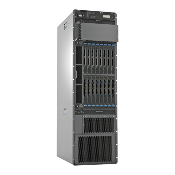
Page 31: Figure 2: Rear View Of The Ptx5000 Packet Transport Switch
Chassis grounding points 5— Control board and Routing Engine Related PTX5000 System Architecture Description on page 7 Documentation PTX5000 Chassis Description on page 12 Overview of Installing the PTX5000 Packet Transport Switch on page 53 Copyright © 2012, Juniper Networks, Inc. - Page 32 PTX5000 Packet Transport Switch Hardware Guide Copyright © 2012, Juniper Networks, Inc.
-
Page 33: Ptx5000 Packet Transport Switch System Architecture Overview
PTX5000 System Architecture Description on page 7 PTX5000 Packet Forwarding Engine Architecture on page 7 PTX5000 System Architecture Description The PTX Series Packet Transport Switches have two main architectural components: Routing Engine—One or more Routing Engines provide Layer 3 routing services and network management. - Page 34 ), located on the switch interface boards, extract the route lookup key and manage the flow of data cells across the switch fabric. Related PTX5000 Packet Transport Switch Description on page 3 Documentation PTX5000 System Architecture Description on page 7 Copyright © 2012, Juniper Networks, Inc.
-
Page 35: Ptx5000 Hardware Components Overview
The PTX5000 Packet Transport Switch supports the components in Table 3 on page 9 listed in alphabetic order. Table 3: PTX5000 Hardware Components Component Model Number Hardware Label CLI Output Description Cable “PTX5000 Cable Management management System” on page 15 system Copyright © 2012, Juniper Networks, Inc. - Page 36 “PTX5000 FPC Description” on FPC-PTX-P1-A page 32 FPC-BLANK Host CB-PTX “PTX5000 Host Subsystem CB-PTX Control Board subsystem Description” on page 35 including RE-DUO-C2600-16G RE-DUO-2600 control board and Routing Engine Midplane “PTX5000 Midplane Midplane-8S Description” on page 14 Copyright © 2012, Juniper Networks, Inc.
-
Page 37: Ptx5000 Component Redundancy
Chapter 3: PTX5000 Hardware Components Overview Table 3: PTX5000 Hardware Components (continued) Component Model Number Hardware Label CLI Output Description P1-PTX-24-10GE-SFPP “PTX Series PIC Description” on P1-PTX 24x 10GE (LAN) page 36 24-10GE-SFPP SFP+ PTX5000 Packet Transport P1-PTX-2-100GE-CFP P1-PTX 2x 100GE CFP... -
Page 38: Ptx5000 Chassis Description
Handles on each side to facilitate positioning the packet transport switch in the rack. Do not use the handles to lift the packet transport switch. Two electrostatic discharge (ESD) points (banana plug receptacles), one front and one rear. Copyright © 2012, Juniper Networks, Inc. -
Page 39: Figure 3: Front View Of Ptx5000 Chassis
Upper horizontal fan tray 8— Lower horizontal fan tray 4— Cable management system 9— Horizontal air filter 5— Vertical fan tray and vertical air filter 10— Power supply module door and power supply modules air filter Copyright © 2012, Juniper Networks, Inc. -
Page 40: Ptx5000 Midplane Description
PIC Concentrator (FPC) card cage. The FPCs install into the midplane from the front of the chassis; and the Switch Interface Boards (SIBs), Routing Engines, control boards, Centralized Clock Generators (CCGs), and power distribution units (PDUs) install into Copyright © 2012, Juniper Networks, Inc. -
Page 41: Ptx5000 Cable Management System
Related PTX5000 FPC Description on page 32 Documentation PTX Series PIC Description on page 36 Maintaining the PTX5000 PIC Cables on page 112 PTX5000 Centralized Clock Generator Overview PTX5000 Centralized Clock Generator Description on page 16 PTX5000 Centralized Clock Generator LEDs on page 17 Copyright ©... -
Page 42: Ptx5000 Centralized Clock Generator Description
, and GPS1 SYNC , for GPS external clock inputs, 5 MHz or 10 MHz. The LEDs for the GPS ports are not supported. Related PTX5000 Centralized Clock Generator LEDs on page 17 Documentation Copyright © 2012, Juniper Networks, Inc. -
Page 43: Ptx5000 Centralized Clock Generator Leds
Related PTX5000 Centralized Clock Generator Description on page 16 Documentation Troubleshooting the PTX5000 Centralized Clock Generators on page 120 PTX5000 Cooling System Overview PTX5000 Cooling System Description on page 18 Copyright © 2012, Juniper Networks, Inc. -
Page 44: Ptx5000 Cooling System Description
Routing Engines, control boards, and SIBs. The vertical fan tray is not interchangeable with the horizontal fan trays. Figure 6: Vertical Fan Tray FAN TRA VER TIC Copyright © 2012, Juniper Networks, Inc. -
Page 45: Airflow
FPCs are installed in cooling zone 1 section 2, the right fans in the horizontal fan trays in cooling zone 1 are set to 30% of maximum speed. Figure 7: Horizontal Fan Tray Airflow Figure 8 on page 20 shows the airflow through the packet transport switch. Copyright © 2012, Juniper Networks, Inc. -
Page 46: Air Filters
One air filter is located inside the vertical fan tray (Figure 9 on page 20). Figure 9: Vertical Fan Tray Air Filter One air filter is located below the lower horizontal fan tray (Figure 10 on page 21). Copyright © 2012, Juniper Networks, Inc. -
Page 47: Power Supply Cooling System
PSMs. Related PTX5000 Clearance Requirements for Airflow and Hardware Maintenance on page 59 Documentation Maintaining the PTX5000 Air Filters on page 109 Maintaining the PTX5000 Fan Trays on page 110 Copyright © 2012, Juniper Networks, Inc. -
Page 48: Ptx5000 Control Board Overview
Each control board consists of the following components (see Figure 12 on page 23) : Ethernet switch used for intermodule communication PCI bus to the Routing Engines Switch Processor Mezzanine Board (SPMB) Figure 12 on page 23 shows the control board. Copyright © 2012, Juniper Networks, Inc. -
Page 49: Figure 12: Control Board
If a packet transport switch contains two host subsystems, connect both control boards to your external management network. Four 10-Gigabit Ethernet SFP+ fiber-optic ports— labeled through (X)GE0 —located to the right of the management ports. (X)GE3 Copyright © 2012, Juniper Networks, Inc. -
Page 50: Ptx5000 Control Board Leds
HOST/ETHERNET port port labeled GE 4 Table 6: Control Board LEDs Label Color State Description MASTER Blue On steadily Control board is functioning as the master. – Control board is functioning as the backup. Copyright © 2012, Juniper Networks, Inc. -
Page 51: Ptx5000 Craft Interface Overview
Troubleshooting the PTX5000 Control Boards on page 135 Troubleshooting the PTX5000 Host Subsystem on page 138 PTX5000 Craft Interface Overview PTX5000 Craft Interface Description on page 26 PTX5000 Craft Interface LEDs on page 28 Copyright © 2012, Juniper Networks, Inc. -
Page 52: Ptx5000 Craft Interface Description
Two configuration switches: The M/S configuration switch must be set to S. The CHASSIS ID configuration switch must always be set to 0. NOTE: The CHASSIS ID configuration switch is set to 0 by default. LEDs Copyright © 2012, Juniper Networks, Inc. -
Page 53: Craft Interface Lcd
Junos OS System Basics and Services Command Reference Alarm Mode When a red or yellow alarm occurs, the LCD switches to alarm mode and reports the alarm condition, as shown in Figure 16 on page Copyright © 2012, Juniper Networks, Inc. -
Page 54: Lcd Navigation Buttons
Four arrow buttons for scrolling up or down, and left or right Related PTX5000 Craft Interface LEDs on page 28 Documentation PTX5000 Craft Interface LEDs Figure 17 on page 29 shows the craft interface LEDs. Copyright © 2012, Juniper Networks, Inc. -
Page 55: Craft Interface Alarm Leds
Possible causes include component removal, failure, or overheating. Yellow On steadily Warning alarm LED—Indicates a serious but nonfatal error condition, such as a maintenance alert or a significant increase in component temperature. Copyright © 2012, Juniper Networks, Inc. -
Page 56: Craft Interface Sib Leds
MASTER FAIL host subsystem LEDs on the craft interface, which indicate the status of the CCGs. The LEDs labeled CCG0 show the status of the Routing Engine in slot CCG0 . The LEDs labeled Copyright © 2012, Juniper Networks, Inc. -
Page 57: Fan Trays Leds
Description Green On steadily The fan tray is functioning normally. On steadily The fan tray has failed. – The fan tray is offline or absent. Related PTX5000 Craft Interface Description on page 26 Documentation Copyright © 2012, Juniper Networks, Inc. -
Page 58: Ptx5000 Fpc Overview
FPC card carrier Four Packet Forwarding Engines, consisting of Lookup ASICs and the Queuing and Memory Interface ASICs Processor Mezzanine Board (PMB), which includes a 1.2-GHz CPU, 4 GB of SDRAM, and two Fast Ethernet interfaces. Copyright © 2012, Juniper Networks, Inc. -
Page 59: Fpc Terminology
Top edge—Edge at the top of the FPC when it is vertical Bottom edge—Edge at the bottom of the FPC when it is vertical Figure 18: FPC Edges Identifying the FPCs Check the label on the faceplate to identify the FPC. Copyright © 2012, Juniper Networks, Inc. -
Page 60: Ptx5000 Fpc Leds
Related PTX5000 FPCs Supported on page 35 Documentation PTX5000 FPC LEDs on page 34 PTX Series PIC Description on page 36 Maintaining the PTX5000 FPCs on page 111 Troubleshooting the PTX5000 FPCs on page 136 PTX5000 FPC LEDs Each FPC has two LEDs—labeled FAULT .Table 14 on page 34... -
Page 61: Ptx5000 Fpcs Supported
In addition, there are LEDs on each Routing Engine and control board. Related PTX5000 Craft Interface LEDs on page 28 Documentation PTX5000 Control Board Description on page 22 Copyright © 2012, Juniper Networks, Inc. -
Page 62: Ptx5000 Pic Overview
PICs are hot-removable and hot-insertable. You can install up to two PICs in each Type 5 FPC. Type 5 PICs have an upper ejector handle and a lower ejector handle. The PTX Series Packet Transport Switches support 10-Gigabit Ethernet, 40-Gigabit Ethernet, and 100-Gigabit Ethernet PICs. Blank PICs resemble other PICs but do not provide any physical connection or activity. -
Page 63: Ptx5000 Power System Overview
The PTX5000 Packet Transport Switch has two redundant, load-sharing power distribution units (PDUs), located at the lower rear of the chassis in slots on the PDU0 right and PDU1 on the left. The PDUs are hot-removable and hot-insertable. Copyright © 2012, Juniper Networks, Inc. -
Page 64: Figure 21: Pdu
Figure 21 on page 38 shows the PDU. Each 120-A DC PDU weighs approximately 60 lb (27.2 kg). Figure 21: PDU 1— Metal handle 4— Circuit breakers 2— Power switch 5— Input power trays 3—Air exhaust ventilation Copyright © 2012, Juniper Networks, Inc. -
Page 65: Ptx5000 Dc Power Supply Module
PSMs Supported The packet transport switch supports the PSM in Table 17 on page Table 17: Supported Power Distribution Units Name Model Number First Supported Junos OS Release DC PSM (120 A) PSM-PTX-DC-120 12.1x48 Copyright © 2012, Juniper Networks, Inc. -
Page 66: Figure 22: Psm
Routing Engines, control boards, CCGs, and SIBs. Channel 1: Routing Engines and control boards Channel 2: SIBs, CCGs, and craft interface Any four FPCs in slots through FPC0 FPC7 Any four FPCs in slots through FPC0 FPC7 Copyright © 2012, Juniper Networks, Inc. -
Page 67: Table 19: Power Zone Fault Tolerance
Connecting DC Power to the PTX5000 Packet Transport Switch on page 94 Powering On the DC Powered PTX5000 Packet Transport Switch on page 96 Maintaining the PTX5000 Power System on page 113 Troubleshooting the PTX5000 Power System on page 139 Copyright © 2012, Juniper Networks, Inc. -
Page 68: Ptx5000 Power Distribution Unit Leds
–40 V. The circuit breaker might have been turned off, the host subsystem detected a failure and turned off the circuit breaker, or the power supply is not receiving any input voltage. Copyright © 2012, Juniper Networks, Inc. -
Page 69: Ptx5000 Power Supply Module Leds
PSM is not enabled or is in a fault condition, or the input voltage to the PSM is too low. – Output is not functioning normally because of a fault condition or the PSM is not receiving input voltage. Copyright © 2012, Juniper Networks, Inc. -
Page 70: Ptx5000 Routing Engine Overview
The Routing Engine constructs and maintains one or more routing tables. From the routing tables, the Routing Engine derives a table of active routes, called the forwarding table, which is then copied into the Packet Forwarding Engine. The design of the ASICs allows Copyright © 2012, Juniper Networks, Inc. -
Page 71: Routing Engine Components
EEPROM—Stores the serial number of the Routing Engine. Interfaces for management access—Provide information about Routing Engine status to the external management devices (console, laptop, or terminal server) connected to the management ports on the control board. Copyright © 2012, Juniper Networks, Inc. -
Page 72: Routing Engine Boot Sequence
The Routing Engine boots from the storage media in this order: the USB device (if present), the CompactFlash card (if present), the disk (if present) in slot 1 , the disk (if SSD1 present) in slot 2 , then the LAN. SSD2 NOTE: is not currently supported. SSD2 Copyright © 2012, Juniper Networks, Inc. -
Page 73: Ptx5000 Routing Engine Leds
There is no disk activity. Blue On steadily Indicates disk activity. SSD2 – There is no disk activity. Green On steadily Indicates activity for the CompactFlash card. – There is no activity for the CompactFlash card. Copyright © 2012, Juniper Networks, Inc. -
Page 74: Ptx5000 Switch Interface Board Overview
SIB. Each SIB weighs 6 lb (2.7 kg). Figure 27: SIB 1— FAIL ACTIVE 2— ONLINE/OFFLINE , and LEDs button Each SIB consists of the following components: Switch fabric ASICs. High-speed links to each FPC. Copyright © 2012, Juniper Networks, Inc. -
Page 75: Ptx5000 Switch Interface Board Leds
No faults have been detected for the SIB. Related PTX5000 Switch Interface Board Description on page 48 Documentation Maintaining the PTX5000 Switch Interface Boards on page 114 Troubleshooting the PTX5000 Switch Interface Boards on page 148 Copyright © 2012, Juniper Networks, Inc. - Page 76 PTX5000 Packet Transport Switch Hardware Guide Copyright © 2012, Juniper Networks, Inc.
-
Page 77: Ptx5000 Packet Transport Switch Initial Installation
Grounding the PTX5000 Packet Transport Switch on page 83 Connecting the PTX5000 Packet Transport Switch to External Devices on page 85 Providing Power to the PTX5000 Packet Transport Switch on page 93 Configuring the Junos OS on page 101 Copyright © 2012, Juniper Networks, Inc. - Page 78 PTX5000 Packet Transport Switch Hardware Guide Copyright © 2012, Juniper Networks, Inc.
-
Page 79: Ptx5000 Packet Transport Switch Installation Summary
“Installing the PTX5000 Mounting Hardware for a Four-Post Rack or Cabinet” on page Install the packet transport switch using a mechanical lift. “Overview of Installing a PTX5000 Packet Transport Switch Using a Mechanical Lift” on page Copyright © 2012, Juniper Networks, Inc. - Page 80 Connect the power, and power on the packet transport switch. “Connecting DC Power to the PTX5000 Packet Transport Switch” on page 94 “Powering On the DC Powered PTX5000 Packet Transport Switch” on page Related PTX5000 Packet Transport Switch Description on page 3 Documentation Copyright © 2012, Juniper Networks, Inc.
-
Page 81: Preparing For Ptx5000 Packet Transport Switch Installation
“PTX5000 Packet Transport Switch Environmental Specifications” on page 257. Verify that the site and installation plan meets all safety guidelines and requirements. “General Safety Guidelines for Juniper Networks Devices” on page 219. Locate sites for connection of system grounding. “PTX5000 Chassis Grounding Cable and Lug Specifications” on page 259. -
Page 82: Rack Requirements For The Ptx5000 Packet Transport Switch
Acquire cables and connectors: Determine the number of cables and type of cable needed based on your planned configuration. “Network Cable and Transceiver Overview for PTX Series Packet Transport Switches” on page 267 PTX5000 Packet Transport Switch PIC Guide Supported Network Interface Standards by Transceiver Review the maximum distance allowed for each cable. - Page 83 Juniper recommends the use of single-sided panel adapters of at least 10 U in height, using as many as needed to fully overlap the chassis rack mount bracket for this type of installation.
-
Page 84: Spacing Of Mounting Bracket And Flange Holes
For maximum stability, also secure the rack to ceiling brackets. Related PTX5000 Chassis Description on page 12 Documentation PTX5000 Physical Specifications on page 255 PTX5000 Installation Safety Guidelines on page 225 Copyright © 2012, Juniper Networks, Inc. -
Page 85: Ptx5000 Clearance Requirements For Airflow And Hardware Maintenance
Maintaining the PTX5000 Air Filters on page 109 Maintaining the PTX5000 Fan Trays on page 110 PTX5000 Physical Specifications on page 255 PTX5000 Installation Safety Guidelines on page 225 Maintenance and Operational Safety Warnings for Juniper Networks Devices on page 234 Copyright © 2012, Juniper Networks, Inc. - Page 86 PTX5000 Packet Transport Switch Hardware Guide Copyright © 2012, Juniper Networks, Inc.
-
Page 87: Unpacking The Ptx5000 Packet Transport Switch
To unpack the packet transport switch and prepare for installation, you need the following tools: Phillips (+) screwdriver, number 2 1/2-in. or 13-mm open-end or socket wrench to remove bracket bolts from the shipping pallet Blank panels to cover any slots not occupied by a component Copyright © 2012, Juniper Networks, Inc. -
Page 88: Unpacking The Ptx5000 Packet Transport Switch
Store the brackets and bolts inside the accessory box. Save the shipping crate cover, pallet, and packing materials in case you need to move or ship the packet transport switch at a later time. Copyright © 2012, Juniper Networks, Inc. -
Page 89: Verifying The Ptx5000 Packet Transport Switch Parts Received
To verify that you have received all parts: Verify that the items on the packing list are included in the parts in the main shipment. Table 24 on page Verify that all parts in the accessory box have been received. Copyright © 2012, Juniper Networks, Inc. -
Page 90: Table 24: Packet Transport Switch Parts List
One blank panel for each slot not occupied by a installed component Table 25: Accessory Box Parts List Part Quantity Screws to mount chassis, Phillips, 12-24 x 1/2 in. , self-tapping Split washers for the grounding cable Copyright © 2012, Juniper Networks, Inc. - Page 91 (DB9 to RJ-45 adapter, straight through) ESD wrist strap with cable Related Overview of Unpacking the PTX5000 Packet Transport Switch on page 61 Documentation Unpacking the PTX5000 Packet Transport Switch on page 62 Copyright © 2012, Juniper Networks, Inc.
- Page 92 PTX5000 Packet Transport Switch Hardware Guide Copyright © 2012, Juniper Networks, Inc.
-
Page 93: Installing The Ptx5000 Packet Transport Switch Mounting Hardware
Table 26: Mounting Hole Locations for Installing the Four-Post Mounting Shelf and Rear-Support Bracket Four-Post Rack Rear Support Hole Distance Above U Division Mounting Shelf Bracket 3.25 in. (8.3 cm) 1.86 U 2.63 in. (6.7 cm) 1.5 U Copyright © 2012, Juniper Networks, Inc. -
Page 94: Table 27: Mounting Hole Locations For Installing A Ptx5000 Packet Transport Switch Chassis In A Four-Post Rack
16.63 in. (42.2 cm) 9.50 U 11.38 in. (28.9 cm) 6.50 U 6.13 in. (15.6 cm) 3.50 U The holes in the front-mounting flanges are spaced at 3 U (5.25 in. or 13.3 cm). Copyright © 2012, Juniper Networks, Inc. -
Page 95: Installing The Four-Post Mounting Shelf And Rear Support Bracket
NOTE: Several holes are provided on top of the shelf. Two holes on each side of the shelf will align with the holes in the rear support bracket. Tighten all the screws completely. Copyright © 2012, Juniper Networks, Inc. -
Page 96: Removing The Center-Mounting Brackets
The center-mounting brackets are not used for a four-post rack, and must be removed from the chassis. To remove the center-mounting brackets from the chassis: Loosen the screws from each bracket (see Figure 33 on page 71). Remove each bracket. Copyright © 2012, Juniper Networks, Inc. -
Page 97: Installing The Ptx5000 Mounting Hardware For An Open-Frame Rack
(see Table 28 on page 72). On the front side of both rack rails, insert cage nuts in the holes specified for mounting the chassis (see Table 29 on page 72). Copyright © 2012, Juniper Networks, Inc. - Page 98 39.38 in. (100.0 cm) 22.50 U 34.13 in. (86.7 cm) 19.50 U 28.88 in. (73.3 cm) 16.50 U 23.63 in. (60.0 cm) 13.50 U 18.38 in. (46.7 cm) 10.50 U 13.13 in. (33.3 cm) 7.50 U Copyright © 2012, Juniper Networks, Inc.
-
Page 99: Installing The Open-Frame Rack Mounting Shelf
Partially insert screws into the open holes in the flanges of the open-frame rack mounting shelf. Tighten all the screws completely. Figure 34: Installing the Mounting Hardware for an Open-Frame Rack Copyright © 2012, Juniper Networks, Inc. - Page 100 PTX5000 Packet Transport Switch Hardware Guide Copyright © 2012, Juniper Networks, Inc.
-
Page 101: Lift
Gather the tools required to install the packet transport switch. “Tools Required to Install the PTX5000 Packet Transport Switch Using a Mechanical Lift” on page Read the safety information in “General Safety Guidelines for Juniper Networks Devices” on page 219 “PTX5000 Installation Safety Guidelines” on page 225. -
Page 102: Mechanical Lift
Lift the chassis slightly above the surface of the mounting shelf, and position it as close as possible to the shelf. Carefully slide the packet transport switch onto the mounting shelf, so that the bottom of the chassis and the mounting shelf overlap by approximately 2 inches. Copyright © 2012, Juniper Networks, Inc. - Page 103 Install a mounting screw into each of the mounting holes aligned with the rack, starting from the bottom. Move the lift away from the rack. Copyright © 2012, Juniper Networks, Inc.
-
Page 104: Figure 35: Loading The Ptx5000 Onto The Lift
PTX5000 Packet Transport Switch Hardware Guide Figure 35: Loading the PTX5000 onto the Lift Copyright © 2012, Juniper Networks, Inc. -
Page 105: Figure 36: Installing The Ptx5000 Packet Transport Switch In An Open-Frame
Chapter 8: Installing the PTX5000 Packet Transport Switch Using a Mechanical Lift Figure 36: Installing the PTX5000 Packet Transport Switch in an Open-Frame Rack Open frame rack Center-mounting bracket Copyright © 2012, Juniper Networks, Inc. -
Page 106: Figure 37: Installing The Ptx5000 Packet Transport Switch In A Four-Post
Table 30: Mounting Hole Locations for Installing a Chassis in an Open-Frame Rack Hole Distance Above U Division 60.38 in. (153.4 cm) 34.50 U 55.13 in. (140.0 cm) 31.50 U 49.88 in. (126.7 cm) 28.50 U 44.63 in. (113.3 cm) 25.50 U Copyright © 2012, Juniper Networks, Inc. -
Page 107: Table 31: Mounting Hole Locations For Installing A Ptx5000 Packet Transport
3.50 U The holes in the front-mounting flanges are spaced at 3 U (5.25 in. or 13.3 cm). Related Overview of Installing a PTX5000 Packet Transport Switch Using a Mechanical Lift Documentation on page 75 Copyright © 2012, Juniper Networks, Inc. - Page 108 PTX5000 Packet Transport Switch Hardware Guide Tools Required to Install the PTX5000 Packet Transport Switch Using a Mechanical Lift on page 76 Copyright © 2012, Juniper Networks, Inc.
-
Page 109: Grounding The Ptx5000 Packet Transport Switch
Verify that a licensed electrician has attached the cable lug provided with the packet transport switch to the grounding cable. Make sure that grounding surfaces are clean and brought to a bright finish before grounding connections are made. Copyright © 2012, Juniper Networks, Inc. -
Page 110: Figure 38: Connecting The Grounding Cable
Figure 38: Connecting the Grounding Cable Related PTX5000 Chassis Description on page 12 Documentation Tools and Parts Required to Ground the PTX5000 Packet Transport Switch on page 83 Copyright © 2012, Juniper Networks, Inc. -
Page 111: Devices
Electrostatic discharge (ESD) grounding wrist strap (provided in the accessory kit) Related Verifying the PTX5000 Packet Transport Switch Parts Received on page 63 Documentation Connecting the PTX5000 Packet Transport Switch to an External Alarm-Reporting Device on page 87 Copyright © 2012, Juniper Networks, Inc. -
Page 112: Connecting The Ptx5000 Packet Transport Switch To A Management Console Or Auxiliary Device
Console port 2— Auxiliary port Related PTX5000 Control Board Description on page 22 Documentation PTX5000 Management Interface Cable Specifications on page 271 RJ-45 Connector Pinouts for the PTX5000 AUXILIARY and CONSOLE Ports on page 272 Copyright © 2012, Juniper Networks, Inc. -
Page 113: Connecting The Ptx5000 Packet Transport Switch To An External Alarm-Reporting Device
Have ready a length of the type of cable used by the PIC. See the PTX5000 Packet Transport Switch PIC Guide If the PIC cable connector port is covered by a rubber safety plug, remove the plug. Copyright © 2012, Juniper Networks, Inc. - Page 114 CAUTION: Do not let fiber-optic cable hang free from the connector. Do not allow fastened loops of cable to dangle, which stresses the cable at the fastening point. Copyright © 2012, Juniper Networks, Inc.
-
Page 115: Figure 40: Connecting Pic Cables
Preventing Electrostatic Discharge Damage to a PTX5000 Packet Transport Switch on page 222 PTX5000 General Laser Safety Guidelines on page 231 Laser Safety Warnings for M Series, MX Series, and T Series Routers, and PTX Series Packet Transport Switches on page 231 Copyright © 2012, Juniper Networks, Inc. -
Page 116: Device
. This port connects to the Routing Engine installed into the control boardin slot Plug the other end of the cable into the network device. Figure 41: Routing Engine Ethernet Cable Connector Copyright © 2012, Juniper Networks, Inc. -
Page 117: Figure 42: Connecting To The Host/Ethernet Port On The Control Board
LED for the port is lit steadily green and that the LED is not LINK FAULT lit. Configure the port. See the statement for PTX Series Packet Transport synchronization Switches in the Junos OS System Basics Configuration Guide Issue the command to check the status of the show chassis synchronization extensive port. - Page 118 : 2011-09-26 17:04:24 PDT Configured sources Source Priority Deviation Last deviation Status (in ppm) (in ppm) bits-a secondary +0.05 +0.05 qualified gps-0-10mhz primary unknown unknown unknown Related PTX5000 Centralized Clock Generator Description on page 16 Documentation Copyright © 2012, Juniper Networks, Inc.
-
Page 119: Providing Power To The Ptx5000 Packet Transport Switch
Phillips (+) screwdriver, number 2 DC power cables, which you must provide. DC power lugs Related PTX5000 Power System Description on page 37 Documentation Connecting DC Power to the PTX5000 Packet Transport Switch on page 94 Copyright © 2012, Juniper Networks, Inc. -
Page 120: Connecting Dc Power To The Ptx5000 Packet Transport Switch
Figure 44 on page 95). Use a 7/16-in. (11 mm) nut driver to tighten the nut. CAUTION: You must use an appropriate torque-controlled tool to tighten the nuts. Applying excessive torque damages the terminal studs and power Copyright © 2012, Juniper Networks, Inc. -
Page 121: Figure 44: Connecting The Dc Source Power Cable Lugs To An Input Power
Verify that the source power cables are connected to the appropriate terminal: the positive (+) source cable to the return terminal (labeled ) and the negative (–) source cable to the input terminal (labeled –48V Copyright © 2012, Juniper Networks, Inc. -
Page 122: Powering On The Dc Powered Ptx5000 Packet Transport Switch
You can monitor the startup process during the initial installation using devices connected to the ports. AUXILIARY CONSOLE Turn on the power to the external management device. Copyright © 2012, Juniper Networks, Inc. - Page 123 If the Routing Engine finishes booting and you need to power off the system, see the “Powering Off the PTX5000 Packet Transport Switch” on page After powering on a power supply, you must wait at least 60 seconds before powering it off. Copyright © 2012, Juniper Networks, Inc.
-
Page 124: Powering Off The Ptx5000 Packet Transport Switch
Switch the circuit breakers on the PDU to the off position ( Repeat steps 3 and 4 for the other PDU. Verify that the LEDs on both PDU faceplate are off. PDU OK CB ON Copyright © 2012, Juniper Networks, Inc. - Page 125 After powering off a power supply, you must wait at least 60 seconds before powering it on again. Related PTX5000 Power System Description on page 37 Documentation Powering On the DC Powered PTX5000 Packet Transport Switch on page 96 Copyright © 2012, Juniper Networks, Inc.
- Page 126 PTX5000 Packet Transport Switch Hardware Guide Copyright © 2012, Juniper Networks, Inc.
-
Page 127: Configuring The Junos Os
Name the packet transport switch will use on the network Domain name the packet transport switch will use IP address and prefix length information for the Ethernet interface IP address of a default packet transport switch Copyright © 2012, Juniper Networks, Inc. -
Page 128: Entering Configuration Mode
Configuring System Attributes Configure the name of the packet transport switch. If the name includes spaces, enclose the name in quotation marks (“ ”). [edit] root@# set system host-name host-name Copyright © 2012, Juniper Networks, Inc. -
Page 129: Committing The Configuration
[edit system services] [edit] set system services telnet Committing the Configuration Display the configuration to verify that it is correct. [edit] root@# show system { host-name host-name; domain-name domain-name; backup-router address; root-authentication { Copyright © 2012, Juniper Networks, Inc. - Page 130 Optionally, configure additional properties by adding the necessary configuration statements. Then commit the changes to activate them. [edit] root@host# commit When you have finished the configuration, exit configuration mode. [edit] root@host# exit root@host> Copyright © 2012, Juniper Networks, Inc.
-
Page 131: Ptx5000 Maintenance, Troubleshooting, And Replacement Procedures
PART 3 PTX5000 Maintenance, Troubleshooting, and Replacement Procedures Maintaining Packet Transport Switch Hardware Components on page 107 Troubleshooting Packet Transport Switch Hardware Components on page 117 Replacing Packet Transport Switch Hardware Components on page 155 Copyright © 2012, Juniper Networks, Inc. - Page 132 PTX5000 Packet Transport Switch Hardware Guide Copyright © 2012, Juniper Networks, Inc.
-
Page 133: Maintaining Packet Transport Switch Hardware Components
Routine Maintenance Procedures for the PTX5000 Packet Transport Switch on page 108 Documentation Maintaining the PTX5000 Centralized Clock Generators on page 108 Maintaining the PTX5000 Control Boards on page 109 Maintaining the PTX5000 Air Filters on page 109 Copyright © 2012, Juniper Networks, Inc. -
Page 134: Routine Maintenance Procedures For The Ptx5000 Packet Transport Switch
During normal operations: The green LED on the CCG faceplate is lit. The yellow LED on the CCG faceplate is not lit. FAIL Issue the show chassis environment ccg command to display information about the CCGs. Copyright © 2012, Juniper Networks, Inc. -
Page 135: Maintaining The Ptx5000 Control Boards
Maintaining PTX5000 Cooling System Components Maintaining the PTX5000 Air Filters on page 109 Maintaining the PTX5000 Fan Trays on page 110 Maintaining the PTX5000 Air Filters Purpose For optimum cooling, verify the condition of the air filters. Copyright © 2012, Juniper Networks, Inc. -
Page 136: Maintaining The Ptx5000 Fan Trays
To display the status of the fans, issue the command. show chassis environment Related PTX5000 Cooling System Description on page 18 Documentation Maintaining the PTX5000 Air Filters on page 109 Troubleshooting the PTX5000 Cooling System on page 122 Copyright © 2012, Juniper Networks, Inc. -
Page 137: Maintaining The Ptx5000 Fpcs
LED on the craft interface is not lit. FAIL Related Maintaining the PTX5000 Control Boards on page 109 Documentation Maintaining the PTX5000 Routing Engines on page 114 Troubleshooting the PTX5000 Host Subsystem on page 138 Copyright © 2012, Juniper Networks, Inc. -
Page 138: Maintaining The Ptx5000 Pics
, top to bottom. Related PTX Series PIC Description on page 36 Documentation Maintaining the PTX5000 PIC Cables on page 112 Troubleshooting the PTX5000 PICs and PIC Cables on page 147 Maintaining the PTX5000 PIC Cables Purpose For optimum performance, verify the condition of the cables. -
Page 139: Maintaining The Ptx5000 Power System
Related PTX Series PIC Description on page 36 Documentation Maintaining the PTX5000 PICs on page 112... -
Page 140: Maintaining The Ptx5000 Routing Engines
Troubleshooting the PTX5000 Host Subsystem on page 138 Troubleshooting the PTX5000 Routing Engines on page 145 Maintaining the PTX5000 Switch Interface Boards Purpose For optimum performance, verify the status of the switch interface boards (SIBs). Copyright © 2012, Juniper Networks, Inc. - Page 141 For more information about the commands, see the Junos OS manuals. Related PTX5000 Switch Interface Board Description on page 48 Documentation PTX5000 Switch Interface Board LEDs on page 49 Troubleshooting the PTX5000 Switch Interface Boards on page 148 Copyright © 2012, Juniper Networks, Inc.
- Page 142 PTX5000 Packet Transport Switch Hardware Guide Copyright © 2012, Juniper Networks, Inc.
-
Page 143: Troubleshooting Packet Transport Switch Hardware Components
Alarm devices connected to the alarm relay contact—When a red or yellow alarm occurs, it trips the corresponding alarm relay contact. CLI—The CLI is the primary tool for controlling and troubleshooting hardware, Junos OS, routing protocols, and network connectivity. CLI commands display information Copyright © 2012, Juniper Networks, Inc. -
Page 144: Ptx5000 Led Overview
CLI to troubleshoot the Junos OS, see the appropriate Junos OS configuration guide. JTAC—If you need assistance during troubleshooting, you can contact the Juniper Networks Technical Assistance Center (JTAC) by using the Web or by telephone. If you encounter software problems, or problems with hardware components not discussed here, contact JTAC. -
Page 145: Component Leds
17 alarms currently active Alarm time Class Description 2011-12-07 11:28:52 PST Minor SIB 8 FPC Link Error 2011-12-07 11:28:52 PST Minor SIB 7 FPC Link Error 2011-12-07 11:28:52 PST Minor SIB 6 FPC Link Error Copyright © 2012, Juniper Networks, Inc. -
Page 146: Chassis Alarm Messages
121, the text in the column labeled ”LCD Message” appears in the display of the craft interface. The text in the column labeled “CLI Message” appears in the output from the command. show chassis alarms Copyright © 2012, Juniper Networks, Inc. -
Page 147: Table 32: Chassis Alarm Messages For The Ccgs
1800 mV 3.3 V 3300 mV 3.3 V bias 3299 mV Bus Revision CCG 1 status: State Online - Master clock Temperature 42 degrees C / 107 degrees F Power 1.2 V bias 1199 mV Copyright © 2012, Juniper Networks, Inc. -
Page 148: Troubleshooting The Ptx5000 Cooling System
Issue the command to get information about the source of an show chassis alarms alarm condition: user@host> show chassis alarms Copyright © 2012, Juniper Networks, Inc. - Page 149 Use the show chassis zones command to verify the status of each cooling zone. user@host> show chassis zones ZONE 0 Status Driving FRU Routing Engine 0 Temperature 72 degrees C / 161 degrees F Condition Copyright © 2012, Juniper Networks, Inc.
- Page 150 FPC 3 Absent FPC 4 Absent FPC 5 PIC 5/0 PIC 5/1 FPC 6 PIC 6/0 Absent PIC 6/1 Absent FPC 7 PIC 7/0 PIC 7/1 Fan Tray 1 Spinning at 31% fan tray speed Copyright © 2012, Juniper Networks, Inc.
-
Page 151: Troubleshooting Temperature Alarms
Warm cb-numberT emperature temperature tray have not failed. Warm exceeded the warm Verify that fans in the vertical fan tray temperature are running at appropriate speed. threshold. Issue the show chassis routing-engine command. Copyright © 2012, Juniper Networks, Inc. - Page 152 Verify that the room temperature is within acceptable limits. Use the show chassis temperature-thresholds to show the temperature thresholds for various components. NOTE: Exhaust A Exhaust B Ambient Exhaust , and Junction correspond to temperature sensors located on the respective hardware component. Copyright © 2012, Juniper Networks, Inc.
- Page 153 PDUs. Check the temperature of components that are monitored for temperature alarms by issuing the command. For more information show chassis environment monitored about temperature alarms, see Table 34 on page 125. Copyright © 2012, Juniper Networks, Inc.
- Page 154 59 degrees C / 138 degrees F FPC 2 TL3 60 degrees C / 140 degrees F FPC 2 TQ3 63 degrees C / 145 degrees F PIC 2/0 Ambient 48 degrees C / 118 degrees F Copyright © 2012, Juniper Networks, Inc.
- Page 155 3299 mV Power 2 1.0 V 1000 mV 3.3 V bias 3312 mV 3.9 V 3961 mV Bus Revision FPGA Revision Use the command to check the temperature of each show chassis environment sib component. Copyright © 2012, Juniper Networks, Inc.
- Page 156 45 degrees C / 113 degrees F Power 1.0 V 1000 mV 1.5 V 1500 mV 1.2 V 1199 mV 3.3 V 3299 mV 0.9 V 900 mV 2.5 V 2500 mV 3.3 V bias 3328 mV SIB 4 status: Copyright © 2012, Juniper Networks, Inc.
- Page 157 Exhaust Temperature 43 degrees C / 109 degrees F Junction Temperature 71 degrees C / 159 degrees F Power 1.0 V 1000 mV 1.5 V 1500 mV 1.2 V 1199 mV 3.3 V 3299 mV Copyright © 2012, Juniper Networks, Inc.
- Page 158 Bias 3.3v 3327 mV 3.3v 3300 mV 2.5v 2500 mV 0.9v 900 mV 12.0v 2014 mV 12.0v 2030 mV Use the show chassis environment command to verify that the status of each component is Copyright © 2012, Juniper Networks, Inc.
- Page 159 34 degrees C / 93 degrees F FPC 0 Intake 32 degrees C / 89 degrees F FPC 0 Exhaust A 50 degrees C / 122 degrees F FPC 0 Exhaust B 43 degrees C / 109 degrees F Copyright © 2012, Juniper Networks, Inc.
- Page 160 PTX5000 Cooling System Description on page 18 Documentation PTX5000 Craft Interface Description on page 26 PTX5000 Craft Interface LEDs on page 28 Maintaining the PTX5000 Air Filters on page 109 Maintaining the PTX5000 Fan Trays on page 110 Copyright © 2012, Juniper Networks, Inc.
-
Page 161: Troubleshooting The Ptx5000 Control Boards
PTX5000 Control Board Description on page 22 Documentation PTX5000 Control Board LEDs on page 24 PTX5000 Host Subsystem Description on page 35 PTX5000 Craft Interface Description on page 26 PTX5000 Craft Interface LEDs on page 28 Copyright © 2012, Juniper Networks, Inc. -
Page 162: Troubleshooting The Ptx5000 Fpcs
Temp CPU Utilization (%) Memory Utilization Slot State Total Interrupt DRAM (MB) Heap Buffer Online 2816 Empty Online 2816 Online 2816 Empty Online 2816 Online 2816 Copyright © 2012, Juniper Networks, Inc. - Page 163 SIB3 Online None SIB4 Online None SIB5 Online None SIB6 Online None SIB7 Online None SIB8 Online None FPC0 Online None FPC1 Empty FPC2 Online None FPC3 Online None FPC4 Empty FPC5 Online None Copyright © 2012, Juniper Networks, Inc.
-
Page 164: Troubleshooting The Ptx5000 Host Subsystem
Use the CLI to check for alarms. Issue the command to view the show chassis alarms alarms. Related PTX5000 Host Subsystem Description on page 35 Documentation Copyright © 2012, Juniper Networks, Inc. -
Page 165: Troubleshooting The Ptx5000 Power System
2. Remove and reinstall the PDU to reset the electronic fuses. PDU pdu-number Not PDU pdu-number Not The PDU is not supported. Install a supported PDU. Recognized Recognized Copyright © 2012, Juniper Networks, Inc. -
Page 166: Table 39: Pdu Leds
To return it for replacement, “Contacting Customer Support” on page 275. Check the status of the power supplies by issuing the show chassis environment pdu command. The output is similar to the following: user@host> show chassis environment pdu Copyright © 2012, Juniper Networks, Inc. - Page 167 PDUs and PSMs. Chassis Power Input(V) Used(W) Total Power 3810 PDU 0 3810 PSM 0 Input 1 PSM 1 Input 1 PSM 2 Input 1 1432 PSM 3 Input 1 1386 Copyright © 2012, Juniper Networks, Inc.
- Page 168 Verify that the DC power cables from the power source to the PDU are not damaged. If the insulation is cracked or broken, immediately replace the DC power cable. If you cannot determine the cause of the problem or need additional assistance, see “Contacting Customer Support” on page 275. Copyright © 2012, Juniper Networks, Inc.
-
Page 169: Troubleshooting The Ptx5000 Power Supply Modules
4. Iif the input is correctly connected, replace the PSM. PSM psm-number Not PSM psm-number Not The packet transport switch does Replace the PSM with a Recognized Recognized not support the power supply supported PSM. module. Copyright © 2012, Juniper Networks, Inc. - Page 170 1386 Issue the command to check the power usage in watts for show chassis power detail hardware components such as FPCs, fan trays, Routing Engine and control board, and SIB, CCG, and craft interface. Copyright © 2012, Juniper Networks, Inc.
-
Page 171: Troubleshooting The Ptx5000 Routing Engines
Junos OS constantly updates the screen with status information for each component. Check the LED on the Routing Engine faceplate. If the LED is red, issue ONLINE ONLINE command to check the status of the Routing Engine. chassis routing-engine user@host> show chassis routing-engine Copyright © 2012, Juniper Networks, Inc. - Page 172 PTX5000 Routing Engine Description on page 44 PTX5000 Routing Engine LEDs on page 47 PTX5000 Craft Interface LEDs on page 28 Maintaining the PTX5000 Routing Engines on page 114 Replacing a PTX5000 C2600 Routing Engine on page 203 Copyright © 2012, Juniper Networks, Inc.
-
Page 173: Troubleshooting The Ptx5000 Pics And Pic Cables
OPNEXT, INC. TRS2001EM-0014 10GBASE SR OPNEXT, INC. TRS2001EM-0014 10GBASE SR SumitomoElectric SPP5200SR-J6-M 10GBASE SR FINISAR CORP. FTLX8571D3BNL-J1 10GBASE SR SumitomoElectric SPP5200SR-J6-M 10GBASE SR SumitomoElectric SPP5200SR-J6-M 10GBASE SR FINISAR CORP. FTLX8571D3BNL-J1 10GBASE SR FINISAR CORP. FTLX8571D3BNL-J1 Copyright © 2012, Juniper Networks, Inc. -
Page 174: Troubleshooting The Ptx5000 Switch Interface Boards
For further description of the output from the command, see the Junos OS System Basics and Services Command Reference Related PTX Series PIC Description on page 36 Documentation Maintaining the PTX5000 PICs on page 112 Maintaining the PTX5000 PIC Cables on page 112... - Page 175 3334 mV SIB 5 status: State Online Intake Temperature 51 degrees C / 123 degrees F Exhaust Temperature 40 degrees C / 104 degrees F Junction Temperature 63 degrees C / 145 degrees F Power Copyright © 2012, Juniper Networks, Inc.
- Page 176 PTX5000 Switch Interface Board LEDs on page 49 PTX5000 Craft Interface Description on page 26 PTX5000 Craft Interface LEDs on page 28 Maintaining the PTX5000 Switch Interface Boards on page 114 Replacing a PTX5000 Switch Interface Board on page 212 Copyright © 2012, Juniper Networks, Inc.
-
Page 177: Troubleshooting The Ptx5000 Switch Fabric
FPC2 Online None FPC3 Empty FPC4 Empty FPC5 Online None FPC6 Empty FPC7 Online None Use the command to check for show chassis fabric summary user@host> show chassis fabric plane-location -Fabric Plane Locations- Planes Copyright © 2012, Juniper Networks, Inc. - Page 178 S06F0_1(7,7,07)-->FPC00FE2TQ2(13) Down FPC00FE3TQ3(13)-->S06F0_1(3,7,11) Down S06F0_1(7,5,07)-->FPC00FE3TQ3(13) Down FPC01FE0TQ0(13)-->S06F0_1(3,0,11) Down S06F0_1(7,2,07)-->FPC01FE0TQ0(13) Down FPC01FE1TQ1(13)-->S06F0_1(3,1,11) Down S06F0_1(7,0,07)-->FPC01FE1TQ1(13) Down FPC01FE2TQ2(13)-->S06F0_1(3,2,11) Down S06F0_1(7,3,07)-->FPC01FE2TQ2(13) Down FPC01FE3TQ3(13)-->S06F0_1(3,3,11) Down S06F0_1(7,1,07)-->FPC01FE3TQ3(13) Down FPC02FE0TQ0(13)-->S06F0_1(2,4,10) OK S06F0_1(6,5,06)-->FPC02FE0TQ0(13) FPC02FE1TQ1(13)-->S06F0_1(2,5,10) OK S06F0_1(6,4,06)-->FPC02FE1TQ1(13) FPC02FE2TQ2(13)-->S06F0_1(2,6,10) OK S06F0_1(6,7,06)-->FPC02FE2TQ2(13) FPC02FE3TQ3(13)-->S06F0_1(2,7,10) OK S06F0_1(6,6,06)-->FPC02FE3TQ3(13) Copyright © 2012, Juniper Networks, Inc.
- Page 179 /var/log/messages To display it, issue the show log command. For example: user@host> show log messages For more information about system log messages, see the Junos OS System Log Messages Reference Copyright © 2012, Juniper Networks, Inc.
- Page 180 PTX5000 Packet Transport Switch Hardware Guide Your customer support representative can assist you with using the information in the system log to determine if you have a faulty SIB or FPC. Copyright © 2012, Juniper Networks, Inc.
-
Page 181: Replacing Packet Transport Switch Hardware Components
Replacing a PTX5000 C2600 Routing Engine on page 203 Replacing a CompactFlash Card in a PTX5000 Routing Engine on page 207 Replacing a Solid-State Disk in a PTX5000 Routing Engine on page 209 Replacing a PTX5000 Switch Interface Board on page 212 Copyright © 2012, Juniper Networks, Inc. -
Page 182: Ptx5000 Field-Replaceable Units
PTX5000 Hardware Component Overview on page 9 Documentation PTX5000 Component Redundancy on page 11 Tools and Parts Required for Replacing Hardware Components To replace hardware components, you need the tools and parts listed in Table 42 on page 157. Copyright © 2012, Juniper Networks, Inc. -
Page 183: Table 42: Tools And Parts Required For Component Replacement
PIC cables Electrostatic bag or antistatic mat Blank panel (if component is not reinstalled) Routing Engine Phillips (+) screwdrivers, numbers 1 and 2 Electrostatic bag or antistatic mat Blank panel (if component is not reinstalled) Copyright © 2012, Juniper Networks, Inc. -
Page 184: Replacing A Centralized Clock Generator
Loosen the captive screws on the edges of the CCG faceplate. Grasp the CCG by the handle on the faceplate and slide it out of the chassis. Place the CCG on the antistatic mat. Copyright © 2012, Juniper Networks, Inc. -
Page 185: Installing A Centralized Clock Generator
To check the status of the CCGs, use the following CLI command: user@host> show chassis environment ccg For more information about using CLI commands, see the Junos OS System Basics and Services Command Reference Figure 47: Installing a CCG Copyright © 2012, Juniper Networks, Inc. -
Page 186: Replacing A Cable Between A Ptx5000 Ccg And An External Clocking
Selected for : 1 hour, 27 minutes, 26 seconds Selected since : 2011-12-09 11:21:07 PST Deviation (in ppm) : +0.51 Last deviation (in ppm): +0.51 Related PTX5000 Centralized Clock Generator Description on page 16 Documentation Copyright © 2012, Juniper Networks, Inc. -
Page 187: Replacing A Ptx5000 Craft Interface
Figure 49 on page 162): Attach an electrostatic discharge (ESD) grounding strap to your bare wrist, and connect the strap to one of the ESD points on the chassis. Locate the ribbon cable on the left side. Copyright © 2012, Juniper Networks, Inc. -
Page 188: Replacing A Ptx5000 Control Board
Preventing Electrostatic Discharge Damage to a PTX5000 Packet Transport Switch on page 222 Replacing a PTX5000 Control Board Removing a PTX5000 Control Board on page 163 Installing a PTX5000 Control Board on page 164 Copyright © 2012, Juniper Networks, Inc. -
Page 189: Removing A Ptx5000 Control Board
Place it on the antistatic mat. CAUTION: Do not stack hardware components on one another after you remove them. Place each component on an antistatic mat resting on a stable, flat surface. Copyright © 2012, Juniper Networks, Inc. -
Page 190: Installing A Ptx5000 Control Board
Slide the control board into the chassis, carefully ensuring that it is correctly aligned. Twist both ejector handles clockwise to seat the host subsystem until the ejectors latch into the faceplate. Install the Routing Engine into the control board. Copyright © 2012, Juniper Networks, Inc. -
Page 191: Figure 52: Installing A Control Board
Contact your customer support representative. To verify that the control board is , use the Online show chassis environment cb command. Figure 52: Installing a Control Board Copyright © 2012, Juniper Networks, Inc. -
Page 192: Replacing A Ptx5000 Horizontal Air Filter
Remove air filter from the air filter tray. Discard the air filter. Copyright © 2012, Juniper Networks, Inc. -
Page 193: Installing A Ptx5000 Horizontal Air Filter
Reinstall the horizontal air filter tray into chassis, and Tighten captive screws to secure the air filter tray. Related PTX5000 Cooling System Description on page 18 Documentation Preventing Electrostatic Discharge Damage to a PTX5000 Packet Transport Switch on page 222 Copyright © 2012, Juniper Networks, Inc. -
Page 194: Replacing A Ptx5000 Vertical Air Filter
Remove the air filter from the air filter tray. Discard the air filter. Figure 55: Vertical Fan Tray Air Filter Copyright © 2012, Juniper Networks, Inc. -
Page 195: Installing A Ptx5000 Vertical Air Filter
Inside the PSM door, locate the air filter retaining bracket at the top of the door. Using a Phillips (+) screwdriver, number 2, remove the 2 screws from the air filter retaining bracket, and remove the bracket. Remove the air filter. Discard the air filter. Copyright © 2012, Juniper Networks, Inc. -
Page 196: Installing The Ptx5000 Psm Air Filter
ESD points on the chassis. Turn off the power to the console or auxiliary device. Pull the cable connector straight out of the port. Disconnect the cable from the console or auxiliary device. Copyright © 2012, Juniper Networks, Inc. -
Page 197: Installing A Management Console Or Auxiliary Port Cable
Removing a PTX5000 Management Ethernet Cable To remove a management Ethernet cable: Attach an electrostatic discharge (ESD) grounding strap to your bare wrist, and connect the strap to one of the ESD points on the chassis. Copyright © 2012, Juniper Networks, Inc. -
Page 198: Installing A Ptx5000 Management Ethernet Cable
PTX5000 Control Board Description on page 22 Documentation Connecting the PTX5000 Packet Transport Switch to a Management Ethernet Device on page 90 Preventing Electrostatic Discharge Damage to a PTX5000 Packet Transport Switch on page 222 Copyright © 2012, Juniper Networks, Inc. -
Page 199: Replacing A Ptx5000 Fpc
CAUTION: Do not leave a fiber-optic transceiver uncovered except when inserting or removing cable. The safety cap keeps the port clean and prevents accidental exposure to laser light. Copyright © 2012, Juniper Networks, Inc. - Page 200 FPC panel over the slot to maintain proper airflow in the FPC card cage. CAUTION: After removing an FPC from the chassis, wait at least 30 seconds before reinserting it, removing an FPC from a different slot, or inserting an FPC into a different slot. Copyright © 2012, Juniper Networks, Inc.
-
Page 201: Installing A Ptx5000 Fpc
If it does not, cover the transceiver with a safety cap. Install each PIC into the appropriate slot on the FPC. For information about installing a PIC, see the installation instructions in “Replacing a PTX5000 PIC” on page 178. Copyright © 2012, Juniper Networks, Inc. -
Page 202: Figure 61: Installing An Fpc
ONLINE OFFLINE P1-PTX 24-10GE -SFPP STATUS ONLINE OFFLINE Gently rest the bottom edge of the FPC on the bottom edge of the slot opening, making contact a short distance forward of the power connector. Copyright © 2012, Juniper Networks, Inc. - Page 203 Services Command Reference CAUTION: After the LED lights steadily, wait at least 30 seconds before removing the FPC again, removing an FPC from a different slot, or inserting an FPC in a different slot. Copyright © 2012, Juniper Networks, Inc.
-
Page 204: Replacing A Ptx5000 Pic
Troubleshooting the PTX5000 FPCs on page 136 Preventing Electrostatic Discharge Damage to a PTX5000 Packet Transport Switch on page 222 Replacing a PTX5000 PIC Removing a PTX5000 PIC on page 179 Installing a PTX5000 PIC on page 180 Copyright © 2012, Juniper Networks, Inc. -
Page 205: Removing A Ptx5000 Pic
Secure the cable so that it is not supporting its own weight as it hangs to the floor. Place excess cable out of the way in a neatly coiled loop in the cable management system. Placing fasteners on the loop helps to maintain its shape. Copyright © 2012, Juniper Networks, Inc. -
Page 206: Installing A Ptx5000 Pic
Secure the cable so that it is not supporting its own weight as it hangs to the floor. Place excess cable out of the way in a neatly coiled Copyright © 2012, Juniper Networks, Inc. -
Page 207: Replacing A Ptx5000 Pic Cable
PIC functioning by issuing the command. show chassis fpc pic-status Related PTX Series PIC Description on page 36 Documentation Troubleshooting the PTX5000 PICs and PIC Cables on page 147 Preventing Electrostatic Discharge Damage to a PTX5000 Packet Transport Switch... -
Page 208: Installing A Ptx5000 Pic Cable
Secure the cable so that it is not supporting its own weight as it hangs to the floor. Place excess cable out of the way in a neatly coiled loop in the cable management system. Placing fasteners on the loop helps to maintain its shape. Copyright © 2012, Juniper Networks, Inc. - Page 209 Junos OS System Basics and Services Command Reference The normal functioning indicator LED confirms that the PIC is online. You can also verify correct PIC functioning by issuing the command. show chassis fpc pic-status Copyright © 2012, Juniper Networks, Inc.
-
Page 210: Replacing A Ptx5000 Pic Sfp+ Transceiver
PTX5000 Packet Transport Switch Hardware Guide Figure 63: Connecting Fiber-Optic Cable to a PIC Related PTX Series PIC Description on page 36 Documentation Troubleshooting the PTX5000 PICs and PIC Cables on page 147 Preventing Electrostatic Discharge Damage to a PTX5000 Packet Transport Switch... -
Page 211: Removing A Ptx5000 Pic Sfp+ Transceiver
Secure the cable so that it is not supporting its own weight as it hangs to the floor. Place excess cable out of the way in a neatly coiled loop in the cable management system. Placing fasteners on the loop helps to maintain its shape. Copyright © 2012, Juniper Networks, Inc. -
Page 212: Installing A Ptx5000 Pic Sfp+ Transceiver
Placing fasteners on the loop helps to maintain its shape. CAUTION: Do not let fiber-optic cable hang free from the connector. Do not allow fastened loops of cable to dangle, which stresses the cable at the fastening point. Copyright © 2012, Juniper Networks, Inc. -
Page 213: Replacing A Ptx5000 Pic Cfp Transceiver
Switch PIC Guide show chassis fpc command. pic-status Related PTX Series PIC Description on page 36 Documentation Troubleshooting the PTX5000 PICs and PIC Cables on page 147 Preventing Electrostatic Discharge Damage to a PTX5000 Packet Transport Switch on page 222... -
Page 214: Installing A Ptx5000 Pic Cfp Transceiver
Arrange the cable in the cable management system to prevent the cable from dislodging or developing stress points. Secure the cable so that it is not supporting its Copyright © 2012, Juniper Networks, Inc. -
Page 215: Replacing A Ptx5000 Horizontal Fan Tray
Switch PIC Guide show chassis fpc command. pic-status Related PTX Series PIC Description on page 36 Documentation Troubleshooting the PTX5000 PICs and PIC Cables on page 147 Preventing Electrostatic Discharge Damage to a PTX5000 Packet Transport Switch on page 222... -
Page 216: Installing A Ptx5000 Horizontal Fan Tray
Grasp the fan tray by its handle and insert it straight into the chassis. Tighten the captive screw on the left side of the fan tray faceplate to secure it in the chassis, using a Phillips (+) screwdriver, number 2. Copyright © 2012, Juniper Networks, Inc. -
Page 217: Replacing A Ptx5000 Vertical Fan Tray
Preventing Electrostatic Discharge Damage to a PTX5000 Packet Transport Switch on page 222 Replacing a PTX5000 Vertical Fan Tray Removing a PTX5000 Vertical Fan Tray on page 192 Installing a PTX5000 Vertical Fan Tray on page 193 Copyright © 2012, Juniper Networks, Inc. -
Page 218: Removing A Ptx5000 Vertical Fan Tray
Place one hand under the fan tray to support it and pull the fan tray completely out of the chassis. WARNING: To avoid injury, keep tools and your fingers away from the fans as you slide the fan tray out of the chassis. The fans might still be spinning. Copyright © 2012, Juniper Networks, Inc. -
Page 219: Installing A Ptx5000 Vertical Fan Tray
Grasp the fan tray handle and insert it straight into the chassis. Tighten the captive screw on the bottom of the fan tray faceplate to secure it in the chassis, using a Phillips (+) screwdriver, number 2. Copyright © 2012, Juniper Networks, Inc. -
Page 220: Replacing A Ptx5000 Pdu
Removing a PTX5000 PDU The PTX5000 Packet Transport Switch has two redundant, load-sharing PDUs. Each PDU is hot-insertable and hot-removable. The PDU weighs 60 lb (27.3 kg). Each input power tray weighs 1.6 lb (0.7 kg). Copyright © 2012, Juniper Networks, Inc. -
Page 221: Figure 71: Removing The Input Power Tray
Loosen the four captive screws attaching the PDU handle to the PDU and chassis. Grasp the handle on the PDU faceplate and pull firmly down toward you. Slide the PDU halfway out of the chassis (see Figure 72 on page 196). Copyright © 2012, Juniper Networks, Inc. -
Page 222: Figure 72: Removing The Pdu
Do not leave a PDU slot empty for more than a short time while the packet transport switch is operational. For proper airflow, the PDU must remain in the chassis or a blank panel must be used in an empty slot. Copyright © 2012, Juniper Networks, Inc. -
Page 223: Installing A Ptx5000 Pdu
Push the metal handle up toward the PDU. Tighten the captive screws on the metal handle. Use a Phillips screwdriver. Slide the input power trays into the new PDU (Figure 74 on page 198). Copyright © 2012, Juniper Networks, Inc. -
Page 224: Replacing A Ptx5000 Pdu Dc Power Cable
Switch the circuit breaker for the input power tray on the PDU faceplate to the off position ( Loosen the captive screws that secure the input power tray to the PDU. Remove the input power tray from the PDU. Copyright © 2012, Juniper Networks, Inc. -
Page 225: Figure 75: Removing The Input Power Tray
Use a 7/16-in. (11 mm) nut driver to loosen the nuts, and remove the nuts from the DC power terminal stud. Remove the DC source power cable lug from the DC power terminal stud. Figure 76: Disconnecting the DC Source Power Cable Lugs to an Input Power Tray Cable restraint Copyright © 2012, Juniper Networks, Inc. -
Page 226: Installing A Ptx5000 Pdu Dc Power Cable
A, and all inputs on the DC PDU in slot must be powered by dedicated power feeds derived from feed PDU1 B. This configuration provides the commonly deployed A/B feed redundancy for the system. Copyright © 2012, Juniper Networks, Inc. -
Page 227: Replacing A Ptx5000 Psm
Close the input power tray cover, and secure it with the screw.. Insert the input power tray into the PDU. Figure 78: Installing an Input Power Tray Replacing a PTX5000 PSM Removing a PTX5000 PSM on page 202 Installing a PTX5000 PSM on page 202 Copyright © 2012, Juniper Networks, Inc. -
Page 228: Removing A Ptx5000 Psm
PSM is receiving power. Verify that the LED on the PSM faceplate is lit steadily. OUTPUT OK Related PTX5000 Power System Description on page 37 Documentation PTX5000 Power Distribution Unit LEDs on page 42 Copyright © 2012, Juniper Networks, Inc. -
Page 229: Replacing A Ptx5000 C2600 Routing Engine
Load averages: 1 minute 5 minute 15 minute 0.04 0.03 0.00 If the host subsystem is functioning as the master, switch it to backup using the CLI command: user@host> request chassis routing-engine master switch Copyright © 2012, Juniper Networks, Inc. - Page 230 To reboot a Routing Engine that has been halted, you must connect through the console. For more information about system commands, see the Junos OS System Basics and Services Command Reference Copyright © 2012, Juniper Networks, Inc.
-
Page 231: Removing A Ptx5000 Routing Engine
Grasp the Routing Engine by the ejector handles and slide it about halfway out of the chassis. Place one of your hands underneath the Routing Engine to support it and slide it completely out of the chassis. Place the Routing Engine on the antistatic mat. Copyright © 2012, Juniper Networks, Inc. -
Page 232: Installing A Ptx5000 Routing Engine
Verify that the Routing Engine is installed correctly and functioning properly: Verify that the green LED lights steadily. ONLINE Verify the status of the Routing Engine using the show chassis routing-engine command. For more information about the commands, see the Junos OS manuals. Copyright © 2012, Juniper Networks, Inc. -
Page 233: Replacing A Compactflash Card In A Ptx5000 Routing Engine
Issue the following CLI command. The master Routing Engine is designated Master in the field: Current state user@host> show chassis routing-engine Routing Engine status: Slot 0: Current state Master Copyright © 2012, Juniper Networks, Inc. -
Page 234: Installing A Compactflash Card In A Ptx5000 Routing Engine
Reinstall the Routing Engine cover and tighten the screws on the corners of the cover to secure it to the Routing Engine (using a Phillips (+) screwdriver, number 2). From the master Routing Engine, issue the request system power-on command to power on the Routing Engine. other-routing-engine Copyright © 2012, Juniper Networks, Inc. -
Page 235: Engine
Removing a Solid-State Disk From a PTX5000 Routing Engine on page 210 Installing a Solid-State Disk in a PTX5000 Routing Engine on page 211 Copying the Junos OS to the Solid-State Disk in a PTX5000 Routing Engine on page 211 Copyright © 2012, Juniper Networks, Inc. -
Page 236: Removing A Solid-State Disk From A Ptx5000 Routing Engine
Do not remove the cover if any of the LEDs on the Routing Engine faceplate are lit. Press the eject button on the right side of the slot to release the SSD. SSD1 DISK 1 Copyright © 2012, Juniper Networks, Inc. -
Page 237: Installing A Solid-State Disk In A Ptx5000 Routing Engine
Wait until a message appears on the console confirming that the snapshot partition procedure is complete. Copyright © 2012, Juniper Networks, Inc. -
Page 238: Replacing A Ptx5000 Switch Interface Board
Place one hand underneath the SIB to support it and slide it completely out of the chassis. Place it on the antistatic mat. CAUTION: Do not stack hardware components on one another after you remove them. Place each component on an antistatic mat resting on a stable, flat surface. Copyright © 2012, Juniper Networks, Inc. -
Page 239: Installing A Ptx5000 Switch Interface Board
SIB faceplate. The green ONLINE/OFFLINE LED on the faceplate begins to blink. Hold the button down until the LED blinks. Issue the following CLI command on the packet transport switch: user@host> request chassis sib online slot 0 Copyright © 2012, Juniper Networks, Inc. -
Page 240: Figure 83: Installing A Sib
PTX5000 Switch Interface Board Description on page 48 Documentation PTX5000 Switch Interface Board LEDs on page 49 Troubleshooting the PTX5000 Switch Interface Boards on page 148 Preventing Electrostatic Discharge Damage to a PTX5000 Packet Transport Switch on page 222 Copyright © 2012, Juniper Networks, Inc. -
Page 241: Appendixes
Packet Transport Switch Environmental Specifications on page 257 Power Guidelines, Requirements, and Specifications on page 259 Packet Transport Switch Cable, Wire, and Pinout Specifications and Guidelines on page 267 Contacting Customer Support and Returning Packet Transport Switch Hardware on page 275 Copyright © 2012, Juniper Networks, Inc. - Page 242 PTX5000 Packet Transport Switch Hardware Guide Copyright © 2012, Juniper Networks, Inc.
-
Page 243: Appendix Aptx5000 Safety And Regulatory Compliance Information
Definition of Safety Warning Levels on page 217 General Safety Guidelines and Warnings on page 219 Fire Safety Requirements for Juniper Networks Devices on page 223 PTX5000 Installation Safety Guidelines on page 225 Installation Safety Warnings for Juniper Networks Devices on page 226... - Page 244 Varning! Denna varningssymbol signalerar fara. Du befinner dig i en situation som kan leda till personskada. Innan du utför arbete på någon utrustning måste du vara medveten om farorna med elkretsar och känna till vanligt förfarande för att förebygga skador. Copyright © 2012, Juniper Networks, Inc.
-
Page 245: General Safety Guidelines And Warnings
Documentation Installation Safety Warnings for Juniper Networks Devices on page 226 Maintenance and Operational Safety Warnings for Juniper Networks Devices on page 234 General Electrical Safety Warnings for Juniper Networks Devices on page 240 DC Power Electrical Safety Warnings for Juniper Networks Devices on page 246... -
Page 246: General Safety Warnings For Juniper Networks Devices
Avoid touching uninsulated electrical wires or terminals that have not been disconnected from their power source. Such an action could cause electrical shock. Related General Safety Warnings for Juniper Networks Devices on page 220 Documentation General Safety Warnings for Juniper Networks Devices... - Page 247 ¡Atención! Esta unidad ha sido diseñada para instalarse en áreas de acceso restringido. Área de acceso restringido significa un área a la que solamente tiene acceso el personal de servicio mediante la utilización de una herramienta Copyright © 2012, Juniper Networks, Inc.
-
Page 248: Switch
Installation Safety Warnings for Juniper Networks Devices on page 226 Documentation Maintenance and Operational Safety Warnings for Juniper Networks Devices on page 234 General Electrical Safety Warnings for Juniper Networks Devices on page 240 DC Power Electrical Safety Warnings for Juniper Networks Devices on page 246... -
Page 249: Fire Safety Requirements For Juniper Networks Devices
Figure 84: ESD Points on the Packet Transport Switch point Figure 85: Placing a Component into an Electrostatic Bag Fire Safety Requirements for Juniper Networks Devices General Fire Safety Requirements on page 224 Fire Suppression on page 224 Fire Suppression Equipment on page 224... -
Page 250: General Fire Safety Requirements
To keep warranties effective, do not use a dry chemical fire extinguisher to control a fire at or near a Juniper Networks hardware equipment. If a dry chemical fire extinguisher is used, the unit is no longer eligible for coverage under a service agreement. -
Page 251: Ptx5000 Installation Safety Guidelines
Appendix A: PTX5000 Safety and Regulatory Compliance Information General Electrical Safety Warnings for Juniper Networks Devices on page 240 DC Power Electrical Safety Warnings for Juniper Networks Devices on page 246 PTX5000 Installation Safety Guidelines Observe the following guidelines before and during packet transport switch installation:... -
Page 252: Installation Safety Warnings For Juniper Networks Devices
PTX5000 Packet Transport Switch Hardware Guide Installation Safety Warnings for Juniper Networks Devices Observe the following warnings before and during hardware equipment installation: Installation Instructions Warning on page 226 Rack-Mounting Requirements and Warnings on page 226 Ramp Warning on page 230... - Page 253 Les directives ci-dessous sont destinées à assurer la protection du personnel: Copyright © 2012, Juniper Networks, Inc.
- Page 254 Advarsel Unngå fysiske skader under montering eller reparasjonsarbeid på denne enheten når den befinner seg i et kabinett. Vær nøye med at systemet er stabilt. Følgende retningslinjer er gitt for å verne om sikkerheten: Copyright © 2012, Juniper Networks, Inc.
- Page 255 Varning! För att undvika kroppsskada när du installerar eller utför underhållsarbete på denna enhet på en ställning måste du vidta särskilda försiktighetsåtgärder för att försäkra dig om att systemet står stadigt. Följande riktlinjer ges för att trygga din säkerhet: Copyright © 2012, Juniper Networks, Inc.
-
Page 256: Ramp Warning
Laser and LED Safety Guidelines and Warnings PTX5000 General Laser Safety Guidelines on page 231 Laser Safety Warnings for M Series, MX Series, and T Series Routers, and PTX Series Packet Transport Switches on page 231 Copyright © 2012, Juniper Networks, Inc. -
Page 257: Ptx5000 General Laser Safety Guidelines
Laser Safety Warnings for M Series, MX Series, and T Series Routers, and PTX Series Packet Transport Switches on page 231 Laser Safety Warnings for M Series, MX Series, and T Series Routers, and PTX Series Packet Transport Switches Class 1 Laser Product Warning on page 231... -
Page 258: Class 1 Led Product Warning
Varoitus Älä katso säteeseen äläkä tarkastele sitä suoraan optisen laitteen avulla. Attention Ne pas fixer le faisceau des yeux, ni l'observer directement à l'aide d'instruments optiques. Warnung Nicht direkt in den Strahl blicken und ihn nicht direkt mit optischen Geräten prüfen. Copyright © 2012, Juniper Networks, Inc. -
Page 259: Radiation From Open Port Apertures Warning
Aviso Dada a possibilidade de emissão de radiação invisível através do orifício da via de acesso, quando esta não tiver nenhum cabo de fibra conectado, deverá evitar a exposição à radiação e não deverá olhar fixamente para orifícios que se encontrarem a descoberto. Copyright © 2012, Juniper Networks, Inc. -
Page 260: Maintenance And Operational Safety Guidelines And Warnings
Installation Safety Warnings for Juniper Networks Devices on page 226 Maintenance and Operational Safety Guidelines and Warnings Maintenance and Operational Safety Warnings for Juniper Networks Devices on page 234 Maintenance and Operational Safety Warnings for Juniper Networks Devices As you maintain the hardware equipment, observe the following warnings:... -
Page 261: Jewelry Removal Warning
Varoitus Ennen kuin työskentelet voimavirtajohtoihin kytkettyjen laitteiden parissa, ota pois kaikki korut (sormukset, kaulakorut ja kellot mukaan lukien). Metalliesineet kuumenevat, kun ne ovat yhteydessä sähkövirran ja maan kanssa, ja ne voivat aiheuttaa vakavia palovammoja tai hitsata metalliesineet kiinni liitäntänapoihin. Copyright © 2012, Juniper Networks, Inc. -
Page 262: Lightning Activity Warning
Do not work on the system or connect or disconnect cables during periods of lightning activity. Waarschuwing Tijdens onweer dat gepaard gaat met bliksem, dient u niet aan het systeem te werken of kabels aan te sluiten of te ontkoppelen. Copyright © 2012, Juniper Networks, Inc. -
Page 263: Operating Temperature Warning
C. Pour permettre un flot d'air constant, dégagez un espace d'au moins 15,2 cm autour des ouvertures de ventilations. Warnung Um einen router der router vor Überhitzung zu schützen, darf dieser nicht in einer Gegend betrieben werden, in der die Umgebungstemperatur Copyright © 2012, Juniper Networks, Inc. -
Page 264: Product Disposal Warning
à toutes les lois et réglementations en vigueur. Warnung Dieses Produkt muß den geltenden Gesetzen und Vorschriften entsprechend entsorgt werden. Avvertenza L'eliminazione finale di questo prodotto deve essere eseguita osservando le normative italiane vigenti in materia Copyright © 2012, Juniper Networks, Inc. -
Page 265: Ptx5000 Electrical Safety Guidelines And Warnings
PTX5000 Electrical Safety Guidelines and Warnings PTX5000 General Electrical Safety Guidelines on page 239 General Electrical Safety Warnings for Juniper Networks Devices on page 240 DC Power Electrical Safety Guidelines and Warnings on page 244 PTX5000 General Electrical Safety Guidelines... -
Page 266: General Electrical Safety Warnings For Juniper Networks Devices
Many components can be removed and replaced without powering off or disconnecting power to the packet transport switch. Never install equipment if it appears damaged. Related General Safety Guidelines for Juniper Networks Devices on page 219 Documentation General Safety Warnings for Juniper Networks Devices on page 220... -
Page 267: Grounding Requirements And Warning
Advarsel Når enheten installeres, må jordledningen alltid tilkobles først og frakobles sist. Aviso Ao instalar a unidade, a ligação à terra deverá ser sempre a primeira a ser ligada, e a última a ser desligada. Copyright © 2012, Juniper Networks, Inc. -
Page 268: Midplane Energy Hazard Warning
å eliminere strøm fra enheten. Aviso Este dispositivo possui mais do que uma conexão de fonte de alimentação de energia; para poder remover a fonte de alimentação de energia, deverão ser desconectadas todas as conexões existentes. Copyright © 2012, Juniper Networks, Inc. -
Page 269: Power Disconnection Warning
¡Atención! Antes de manipular el chasis de un equipo o trabajar cerca de una fuente de alimentación, desenchufar el cable de alimentación en los equipos de corriente alterna (CA); cortar la alimentación desde el interruptor automático en los equipos de corriente continua (CC). Copyright © 2012, Juniper Networks, Inc. -
Page 270: Dc Power Electrical Safety Guidelines And Warnings
överspänningsskyddet. Related DC Power Electrical Safety Warnings for Juniper Networks Devices on page 246 Documentation DC Power Electrical Safety Guidelines and Warnings PTX5000 DC Power Electrical Safety Guidelines on page 244... -
Page 271: Site Electrical Wiring Guidelines For Juniper Networks Devices
Appendix A: PTX5000 Safety and Regulatory Compliance Information Site Electrical Wiring Guidelines for Juniper Networks Devices Distance Limitations for Signaling on page 245 Radio Frequency Interference on page 245 Electromagnetic Compatibility on page 245 Distance Limitations for Signaling Improperly installed wires can emit radio interference. In addition, the potential for damage from lightning strikes increases if wires exceed recommended distances or if wires pass between buildings. -
Page 272: Dc Power Electrical Safety Warnings For Juniper Networks Devices
PTX5000 Packet Transport Switch Hardware Guide DC Power Electrical Safety Warnings for Juniper Networks Devices When working with DC-powered equipment, observe the following warnings: DC Power Copper Conductors Warning on page 246 DC Power Disconnection Warning on page 246 DC Power Wiring Terminations Warning on page 248... - Page 273 Varning! Innan du utför någon av följande procedurer måste du kontrollera att strömförsörjningen till likströmskretsen är bruten. Kontrollera att all strömförsörjning är BRUTEN genom att slå AV det överspänningsskydd som skyddar likströmskretsen och tejpa fast överspänningsskyddets omkopplare i FRÅN-läget. Copyright © 2012, Juniper Networks, Inc.
- Page 274 ¡Atención! Cuando se necesite hilo trenzado, utilizar terminales para cables homologados, tales como las de tipo "bucle cerrado" o "espada", con las lengüetas de conexión vueltas hacia arriba. Estos terminales deberán ser del Copyright © 2012, Juniper Networks, Inc.
-
Page 275: Agency Approvals And Compliance Statements
Storleken på dessa kontakter måste vara avpassad till ledningarna och måste kunna hålla både isoleringen och ledaren fastklämda. Related General Electrical Safety Warnings for Juniper Networks Devices on page 240 Documentation Agency Approvals and Compliance Statements PTX5000 Agency Approvals on page 249... -
Page 276: Ptx5000 Compliance Statements For Nebs
PTX5000 Agency Approvals on page 249 Documentation Compliance Statements for EMC Requirements for Juniper Networks Devices (Canada) This Class A digital apparatus complies with Canadian ICES-003. Cet appareil numérique de la classe A est conforme à la norme NMB-003 du Canada. -
Page 277: Community)
Appendix A: PTX5000 Safety and Regulatory Compliance Information Related Compliance Statements for EMC Requirements for Juniper Networks Devices (Japan) Documentation on page 253 Compliance Statements for EMC Requirements for Juniper Networks Devices (United States) on page 253 PTX5000 Compliance Statements for EMC Requirements (European Community) This is a Class A product. -
Page 278: Figure 86: Declaration Of Conformity
PTX5000 Packet Transport Switch Hardware Guide Figure 86: Declaration of Conformity Related PTX5000 Agency Approvals on page 249 Documentation Copyright © 2012, Juniper Networks, Inc. -
Page 279: (Japan)
Compliance Statements for EMC Requirements for Juniper Networks Devices (United States) on page 253 Compliance Statements for EMC Requirements for Juniper Networks Devices (United States) The hardware equipment has been tested and found to comply with the limits for a Class A digital device, pursuant to Part 15 of the FCC Rules. - Page 280 PTX5000 Packet Transport Switch Hardware Guide The emitted sound pressure is below 70dB(A) per EN ISO 7779. Related PTX5000 Compliance Statements for NEBS on page 250 Documentation Copyright © 2012, Juniper Networks, Inc.
-
Page 281: Appendix B Packet Transport Switch Physical Specifications
FPCs with PICs installed: Up to 30 lb (13.6 kg) FPC without PICs installed: up to 25 lb (11.4 kg) Blank panel in FPC slot: 6.9 lb (3.1 kg) PIC weight 5 lb (2.3 kg) Copyright © 2012, Juniper Networks, Inc. -
Page 282: Table 43: Physical Specifications
Vertical air filter weight 7.6 lb (3.5 kg) CCG weight 2 lb (0.9 kg) Related PTX5000 Packet Transport Switch Description on page 3 Documentation PTX5000 Chassis Description on page 12 PTX5000 Installation Safety Guidelines on page 225 Copyright © 2012, Juniper Networks, Inc. -
Page 283: Appendix C Packet Transport Switch Environmental Specifications
Articles 110-16, 110-17, and 110-18 of the National Electrical Code, ANSI/NFPA Related Routine Maintenance Procedures for the PTX5000 Packet Transport Switch on page 108 Documentation General Safety Guidelines for Juniper Networks Devices on page 219 Copyright © 2012, Juniper Networks, Inc. - Page 284 PTX5000 Packet Transport Switch Hardware Guide Copyright © 2012, Juniper Networks, Inc.
-
Page 285: Appendix D Power Guidelines, Requirements, And Specifications
Figure 87 on page 260 can also used for the DC power cables. CAUTION: Before packet transport switch installation begins, a licensed electrician must attach a cable lug to the grounding cable that you supply. Copyright © 2012, Juniper Networks, Inc. -
Page 286: Ptx5000 Dc Power System Electrical Specifications
PTX5000 DC Power System Electrical Specifications Table 46 on page 260 lists the DC power system electrical specifications. Table 46: Power System Electrical Specifications Item Specification DC input voltage Operating range: –40.0 to –72.0 VDC Copyright © 2012, Juniper Networks, Inc. -
Page 287: Ptx5000 Dc Power Distribution Unit Specifications
Connecting DC Power to the PTX5000 Packet Transport Switch on page 94 PTX5000 DC Power System Electrical Specifications on page 260 PTX5000 DC Power Requirements on page 262 PTX5000 DC Power Cable and Lugs Specifications on page 263 Copyright © 2012, Juniper Networks, Inc. -
Page 288: Ptx5000 Dc Power Requirements
Base System + 1 FPC + 1 PIC= 28.2 A + 11.6 A + 0.7 A = 40.5 A @ –48 VDC = 1944 W Example of calculating power consumption for a maximum configuration: Copyright © 2012, Juniper Networks, Inc. -
Page 289: Ptx5000 Dc Power Cable And Lugs Specifications
Before packet transport switch installation begins, a licensed electrician must attach a cable lug to the power cables that you supply. A cable with an incorrectly attached lug can damage the packet transport switch. Copyright © 2012, Juniper Networks, Inc. -
Page 290: Dc Power Lugs
B. This configuration provides the commonly deployed A/B feed redundancy for the system. Related PTX5000 Power System Description on page 37 Documentation Connecting DC Power to the PTX5000 Packet Transport Switch on page 94 Copyright © 2012, Juniper Networks, Inc. - Page 291 Maintaining the PTX5000 Power System on page 113 PTX5000 DC Power System Electrical Specifications on page 260 PTX5000 DC Power Cable and Lugs Specifications on page 263 PTX5000 DC Power Distribution on page 264 Copyright © 2012, Juniper Networks, Inc.
- Page 292 PTX5000 Packet Transport Switch Hardware Guide Copyright © 2012, Juniper Networks, Inc.
-
Page 293: Packet Transport Switch Cable, Wire, And Pinout Specifications And Guidelines
Calculating Power Budget and Power Margin for Fiber-Optic Cables on page 269 Network Cable and Transceiver Overview for PTX Series Packet Transport Switches PTX Series Packet Transport Switches support a variety of fixed and pluggable transceivers and network cable, including multimode and single-mode fiber-optic cable. -
Page 294: Dispersion
An efficient optical data link must have enough light to exceed the minimum power that the receiver requires to operate within its specifications. In addition, the total dispersion must be less than the limits specified for the type of link in Telcordia Technologies Copyright © 2012, Juniper Networks, Inc. -
Page 295: Calculating Power Budget And Power Margin For Fiber-Optic Cables
Calculating Power Budget and Power Margin for Fiber-Optic Cables on page 269 Documentation Network Cable and Transceiver Overview for PTX Series Packet Transport Switches on page 267 Network Cable and Transceiver Overview for M Series, MX Series, and T Series Routers... -
Page 296: Table 50: Estimated Values For Factors Causing Link Loss
) as the sum of fiber attenuation (8 km @ 0.5 dB/km, or 4 dB) and loss for seven connectors (0.5 dB per connector, or 3.5 dB). The power margin ( ) is calculated as follows: – LL Copyright © 2012, Juniper Networks, Inc. -
Page 297: Ptx5000 Management Interface Cable Specifications
Network Cable and Transceiver Overview for M Series, MX Series, and T Series Routers Documentation Network Cable and Transceiver Overview for PTX Series Packet Transport Switches on page 267 h t t p : / / w w w . j u n i p e r . n e t / t e c h p u b s / e n _ U S / r e l e a s e - i n d e p e n d e n t / j u n o s / t o p i c s / r e f e r e n c e / g e n e r a l / t r a n s c e i v e r - m - m x - t - s e r i e s - s t a n d a r d s - b y - m o d e l . h t m l... -
Page 298: Port
The ports are configured as data terminal equipment (DTE). Table 53 on page 272 describes the RJ-45 connector pinouts. Table 53: RJ-45 Connector Pinouts for the PTX5000 AUXILIARY and CONSOLE Ports Signal Direction Description <– Carrier Detect <– Receive Data Copyright © 2012, Juniper Networks, Inc. -
Page 299: Ptx5000 Alarm Relay Contact Wire Specifications
You must provide a wire with gauge between 28-AWG and 14-AWG (0.08 and 2.08 Related PTX5000 Craft Interface Description on page 26 Documentation Connecting the PTX5000 Packet Transport Switch to an External Alarm-Reporting Device on page 87 Copyright © 2012, Juniper Networks, Inc. - Page 300 PTX5000 Packet Transport Switch Hardware Guide Copyright © 2012, Juniper Networks, Inc.
-
Page 301: Contacting Customer Support And Returning Packet Transport Switch
PTX5000 Component Serial Number Locations on page 280 Contacting Customer Support You can contact Juniper Networks Technical Assistance Center (JTAC) 24 hours a day, 7 days a week in one of the following ways: On the Web, using the Case Manager link at: http://www.juniper.net/support/... -
Page 302: Returning A Hardware Component To Juniper Networks, Inc
NOTE: Do not return any component to Juniper Networks, Inc. unless you have first obtained an RMA number. Juniper Networks, Inc. reserves the right to refuse shipments that do not have an RMA. Refused shipments will be returned to the customer by collect freight. -
Page 303: Tools And Parts Required To Remove Components From A Ptx5000 Packet Transport Switch
To pack the packet transport switch for shipment: Retrieve the shipping crate and packing materials in which the packet transport switch was originally shipped. If you do not have these materials, contact your Juniper Networks representative about approved packaging materials. -
Page 304: Packing The Packet Transport Switch Components For Shipment
Displaying PTX5000 Component Serial Numbers on page 278 PTX5000 Component Serial Number Locations on page 280 Returning a Hardware Component to Juniper Networks, Inc. on page 276 Displaying PTX5000 Component Serial Numbers Before contacting Juniper Networks, Inc. to request a Return Materials Authorization (RMA), you must find the serial number on the packet transport switch or component. - Page 305 REV 10 711-030686 EG5418 SNG PMB SPMB 1 REV 09 711-030686 EG5373 SNG PMB SIB 0 REV 07 750-030631 EG4858 SIB-I-8S SIB 1 REV 07 750-030631 EG4872 SIB-I-8S SIB 2 REV 07 750-030631 EG4866 SIB-I-8S Copyright © 2012, Juniper Networks, Inc.
-
Page 306: Ptx5000 Component Serial Number Locations
PTX5000 Component Serial Number Locations on page 280 Documentation Contacting Customer Support on page 275 Returning a Hardware Component to Juniper Networks, Inc. on page 276 PTX5000 Component Serial Number Locations Horizontal Air Filter Serial Number Label on page 280... -
Page 307: Chassis Serial Number Label
Figure 91 on page 281). Figure 91: Chassis Serial Number Label CCG Serial Number Label The serial number label is located on the middle right of the CCG (see Figure 92 on page 282). Copyright © 2012, Juniper Networks, Inc. -
Page 308: Control Board Serial Number Label
Figure 93: Control Board Serial Number Label Craft Interface Serial Number Label The serial number label is located on the front right side of the craft interface (see Figure 94 on page 282). Figure 94: Craft Interface Serial Number Label Copyright © 2012, Juniper Networks, Inc. -
Page 309: Horizontal Fan Tray Serial Number Label
The serial number label is located on the upper left side of the vertical fan tray (see Figure 96 on page 283). Figure 96: Vertical Fan Tray Serial Number Label FAN TRA VER TIC Copyright © 2012, Juniper Networks, Inc. -
Page 310: Fpc Serial Number Label
ONL INE OFF LINE EF4381 PIC Serial Number Label The serial number label for the 10-Gigabit Ethernet PIC is located on the lower right side of the PIC (see Figure 98 on page 285). Copyright © 2012, Juniper Networks, Inc. -
Page 311: Figure 98: 10-Gigabit Ethernet Pic Serial Number Label
EF4643 The serial number label for the 40-Gigabit Ethernet PIC is located on the upper right side of the PIC (see Figure 99 on page 285). Figure 99: 40-Gigabit Ethernet PIC Serial Number Label Copyright © 2012, Juniper Networks, Inc. -
Page 312: Pdu Serial Number Label
Figure 100 on page 286). Figure 100: 100-Gigabit Ethernet PIC Serial Number Label PDU Serial Number Label The serial number label is located on the faceplate of the PDU (see Figure 101 on page 287). Copyright © 2012, Juniper Networks, Inc. -
Page 313: Psm Serial Number Label
Figure 101: PDU Serial Number Label PSM Serial Number Label The serial number label is located on the front right side of the PSM (see Figure 102 on page 287). Figure 102: PSM Serial Number Label S/N: ZB00030 Copyright © 2012, Juniper Networks, Inc. -
Page 314: Routing Engine Serial Number Label
288). Figure 104: SIB Serial Number Label Related Displaying PTX5000 Component Serial Numbers on page 278 Documentation Contacting Customer Support on page 275 Returning a Hardware Component to Juniper Networks, Inc. on page 276 Copyright © 2012, Juniper Networks, Inc. -
Page 315: Index
PART 5 Index Index on page 291 Copyright © 2012, Juniper Networks, Inc. - Page 316 PTX5000 Packet Transport Switch Hardware Guide Copyright © 2012, Juniper Networks, Inc.
-
Page 317: Index
(RJ-45)......272 compatibility, electromagnetic........245 compliance EMC requirements..........250, battery general standards............249 environmental compliance........253 components lithium................253 chassis.................12 braces, in configuration statements......xxiii cooling system..............18 brackets field replacement............156 angle, in syntax descriptions........xxiii FPCs..................32 square, in configuration statements.....xxiii midplane................14 Copyright © 2012, Juniper Networks, Inc. - Page 318 (HOL)........268 EIA rack standards..............56 hot-pluggable components, description.....156 electricity humidity (relative), acceptable........257 safety warnings............240 site wiring guidelines..........245 immunity standards............249 Copyright © 2012, Juniper Networks, Inc.
- Page 319 PIC................112 securing to building............58 FPC..................111 size and strength required..........56 PIC..................112 standards, EIA and ETSI..........56 warnings................234 radio frequency interference, preventing....245 manuals redundancy..................11 comments on..............xxiii relative humidity, acceptable...........257 RFI....................245 Copyright © 2012, Juniper Networks, Inc.
- Page 320 See also cable, PIC chassis................255 electrical components..............255 cable and wiring..........245 wiring, electrical See electricity environmental...............257 fire safety.................223 power drawn by hardware components....262 power system..............262 rack connection to building structure.....58 front-mount flange hole spacing....58 Copyright © 2012, Juniper Networks, Inc.
Need help?
Do you have a question about the PTX Series and is the answer not in the manual?
Questions and answers