Table of Contents
Advertisement
Quick Links
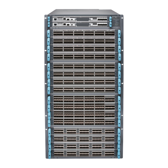
PTX10016 Router Quick Start Guide
December 2017
Part Number: 530-079089
Revision 01
Contents
Copyright © 2018, Juniper Networks, Inc.
This document describes how to install the Juniper Networks
Quick Start Description . . . . . . . . . . . . . . . . . . . . . . . . . . . . . . . . . . . . . . . . . . . . . . . 2
Step 1-Preparing the Site for the PTX10016 . . . . . . . . . . . . . . . . . . . . . . . . . . . . . . . 2
Rack-Mounting Requirements . . . . . . . . . . . . . . . . . . . . . . . . . . . . . . . . . . . . . . 2
Clearance Requirements . . . . . . . . . . . . . . . . . . . . . . . . . . . . . . . . . . . . . . . . . . . 3
Cooling and Airflow Requirements . . . . . . . . . . . . . . . . . . . . . . . . . . . . . . . . . . . 3
Step 2-Unpacking the PTX10016 . . . . . . . . . . . . . . . . . . . . . . . . . . . . . . . . . . . . . . . 4
Step 3-Mounting the Router Chassis . . . . . . . . . . . . . . . . . . . . . . . . . . . . . . . . . . . . 8
Installing the Mounting Hardware . . . . . . . . . . . . . . . . . . . . . . . . . . . . . . . . . . . 8
Mounting the PTX10016 Using a Mechanical Lift . . . . . . . . . . . . . . . . . . . . . . . 10
Step 4-Installing Line Cards . . . . . . . . . . . . . . . . . . . . . . . . . . . . . . . . . . . . . . . . . . . 12
Step 5-Installing the Front Panel . . . . . . . . . . . . . . . . . . . . . . . . . . . . . . . . . . . . . . 15
Step 6-Connecting Power to the Chassis . . . . . . . . . . . . . . . . . . . . . . . . . . . . . . . . 17
Ground the Chassis . . . . . . . . . . . . . . . . . . . . . . . . . . . . . . . . . . . . . . . . . . . . . . 17
Install AC Power Supplies . . . . . . . . . . . . . . . . . . . . . . . . . . . . . . . . . . . . . . . . 20
Install DC Power Supplies . . . . . . . . . . . . . . . . . . . . . . . . . . . . . . . . . . . . . . . . . 23
Step 7-Connecting to the Network . . . . . . . . . . . . . . . . . . . . . . . . . . . . . . . . . . . . . 29
Step 8-Performing Initial Configuration . . . . . . . . . . . . . . . . . . . . . . . . . . . . . . . . . 30
Safety Warnings Summary . . . . . . . . . . . . . . . . . . . . . . . . . . . . . . . . . . . . . . . . . . . . 31
Power Cable Warning (Japanese) . . . . . . . . . . . . . . . . . . . . . . . . . . . . . . . . . . 32
Junos OS Documentation and Release Notes . . . . . . . . . . . . . . . . . . . . . . . . . . . . . 32
Requesting Technical Support . . . . . . . . . . . . . . . . . . . . . . . . . . . . . . . . . . . . . . . . . 33
Self-Help Online Tools and Resources . . . . . . . . . . . . . . . . . . . . . . . . . . . . . . . 33
Opening a Case with JTAC . . . . . . . . . . . . . . . . . . . . . . . . . . . . . . . . . . . . . . . . 33
Revision History . . . . . . . . . . . . . . . . . . . . . . . . . . . . . . . . . . . . . . . . . . . . . . . . . . . . 34
®
PTX10016 Router Chassis.
1
Advertisement
Table of Contents

Related Manuals for Juniper PTX10016


Summary of Contents for Juniper PTX10016
-
Page 1: Table Of Contents
Quick Start Description ..........2 Step 1–Preparing the Site for the PTX10016 ....... 2 Rack-Mounting Requirements . -
Page 2: Quick Start Description
The router chassis ships in a cardboard box that has a two-layer wooden pallet base. The router chassis is bolted to the pallet base. You can install a PTX10016 router in a standard 19 in. (48.26 cm) equipment rack by using the supplied rack-mounting kit and the front-mounting bracket that is attached to the chassis. -
Page 3: Clearance Requirements
12" (30.5 cm) For airflow For airflow If you are mounting a PTX10016 in a rack with other equipment, ensure that the exhaust from other equipment does not blow into the intake vents of the chassis. Cooling and Airflow Requirements The cooling system in a PTX10016 chassis consists of dual fan trays and dual fan tray controllers. -
Page 4: Step 2-Unpacking The Ptx10016
Leave at least 24 in. (61 cm) both in front of and behind the PTX10016 for service personnel to remove and install hardware components. To be NEBS GR-63 compliant, allow at least 30 in. - Page 5 The shipper has the option to either ship the front panel separately or to ship along with the chassis. If the front panel arrives with the chassis, set aside the front panel box until you are ready to verify the contents of the order. Copyright © 2018, Juniper Networks, Inc.
- Page 6 PTX10016 Router Quick Start Guide To unpack the chassis (see Figure 3 on page Figure 3: Shipping Crate and Accessory Box Move the shipping box to a staging area as close to the installation site as possible. While the chassis is bolted to the pallet, you can use a forklift or pallet jack to move it.
- Page 7 Verify that your order includes all appropriate parts. Store the brackets and bolts inside the accessory box. Save the shipping box and packing materials in case you need to move or ship the router at a later time. Copyright © 2018, Juniper Networks, Inc.
-
Page 8: Step 3-Mounting The Router Chassis
PTX10016 Router Quick Start Guide Step 3–Mounting the Router Chassis To install the PTX10016, first install the mounting hardware and then use a mechanical lift to load the chassis into the rack. Installing the Mounting Hardware on page 8 Mounting the PTX10016 Using a Mechanical Lift on page 10 Installing the Mounting Hardware Install the mounting hardware on the rack before installing the router. - Page 9 Rear adjustable mounting brackets Position the right front adjustable mounting bracket at the desired position in the right side of the rack opposite the installed left front bracket, so that it is on the same rack Copyright © 2018, Juniper Networks, Inc.
-
Page 10: Mounting The Ptx10016 Using A Mechanical Lift
Hand-tighten the screws fully (to 12–16 in.-lb torque) using a number 2 Phillips screwdriver. Mounting the PTX10016 Using a Mechanical Lift Because of the router's size and weight, the PTX10016 can safely be installed only by using a mechanical lift. CAUTION: Do not install line cards in the chassis until after you mount the chassis securely on a rack or cabinet. - Page 11 Load the router onto the lift, making sure it rests securely on the lift platform. Figure 6: Loading the PTX10016 into a Rack By Using a Mechanical Lift Using the lift, align the router in front of the rack, centering it in front of the mounting brackets.
-
Page 12: Step 4-Installing Line Cards
PTX10016 Router Quick Start Guide Lift the chassis approximately 0.75 in. (1.9 cm) above the surface of the mounting brackets. Align the chassis as close as possible to the mounting brackets. Carefully slide the chassis onto the adjustable mounting brackets until the front-mounting brackets attached to the chassis contact the rack rails. - Page 13 Figure 9: Removing the Cover Panel for a Line Card CAUTION: Do not lift the line card by holding the edge connectors or the handles on the faceplate. Neither the handles or the edge connectors can Copyright © 2018, Juniper Networks, Inc.
- Page 14 PTX10016 Router Quick Start Guide support the weight of the line card. Lifting the line card by the handles or edge connectors might bend them, which would prevent the line cards from being properly seated in the chassis. See Figure 10 on page Figure 10: Line Card Connectors 1—...
-
Page 15: Step 5-Installing The Front Panel
You can install the optional cable management kit after the card is installed. Step 5–Installing the Front Panel The front panel is required on the PTX10016 to protect fiber optic cabling and to provide additional protection from electromagnetic interference (EMI). The front panel can be installed with or without the optional cable management system. - Page 16 PTX10016 Router Quick Start Guide Use the Phillips screwdriver to attach two mounting screws to the right base bracket at the bottom right side of the chassis frame. Use the Phillips screwdriver to attach two mounting screws to the latch bracket at...
-
Page 17: Step 6-Connecting Power To The Chassis
Step 6–Connecting Power to the Chassis Figure 14: Front Panel Installation Step 6–Connecting Power to the Chassis Before supplying power to the PTX10016, ensure that you complete these tasks: Ground the Chassis on page 17 Install AC Power Supplies on page 20... - Page 18 Grounding lug for your grounding cable (provided)—This bracket attaches to the lower left corner of the PTX10016 router chassis next to PSU 9, providing a protective earthing terminal for the router. The grounding lug required is a Panduit LCD6-10A-L or equivalent.
- Page 19 Place the chassis grounding lug and cable over the PEM nuts with the cable connection pointing to the left. See Figure 16 on page Figure 16: Connecting a Grounding Cable to the PTX10016 Place the two screws over the grounding lug and grounding cable. Copyright © 2018, Juniper Networks, Inc.
-
Page 20: Install Ac Power Supplies
Install AC Power Supplies PTX10016 power supplies are hot-insertable and are field-replaceable units (FRUs). You can install up to 10 power supplies in a PTX10016. The power supplies install in the rear of the chassis in the slots provided along the left side. - Page 21 (see Figure 18 on page 22). Push the captive screw into the power supply faceplate. Ensure that the screw is seated inside the corresponding hole on the faceplate. Copyright © 2018, Juniper Networks, Inc.
- Page 22 PTX10016 Router Quick Start Guide Tighten the captive screw by turning it clockwise by using the Phillips (+) screwdriver, number 1. When the screw is completely tight, the latch locks into the router chassis. Figure 18: Installing an AC Power Supply Locate two power cords shipped with the router;...
-
Page 23: Install Dc Power Supplies
Install DC Power Supplies PTX10016 power supplies are hot-insertable and are field-replaceable units (FRUs). You can install up to 10 power supplies in a PTX10016. The power supplies install in the rear of the chassis in the slots provided along the left side. - Page 24 Electrostatic discharge (ESD) grounding strap DC power source cables (not provided) with the cable lugs (provided) attached The provided terminal lugs in a PTX10016 are sized for 4 AWG (21.1 mm ) power source cables. The DC power source cables that you provide must be 4 AWG (21.1 mm...
- Page 25 INPUT 2: : RTN –48V/–60V supply must be powered by dedicated power feeds derived from feed INPUT 1 and feed INPUT 2. This configuration provides the commonly deployed INPUT 1 / INPUT 2 feed redundancy for the router. Copyright © 2018, Juniper Networks, Inc.
- Page 26 PTX10016 Router Quick Start Guide Figure 20: Connecting the DC Power Supply Cables to a PTX10016 Install the plastic cable cover over each set of power cables by using the Phillips (+) screwdriver, number 2, to tighten the screw. If the power supply slot on the chassis has a cover panel on it, insert your thumb and forefinger into the finger holes, then squeeze and pull the cover out of the slot.
- Page 27 Tighten the captive screw by turning it clockwise by using the Phillips (+) screwdriver, number 1. When the screw is completely tight, the latch locks into the router chassis. Copyright © 2018, Juniper Networks, Inc.
- Page 28 PTX10016 Router Quick Start Guide Figure 22: Installing a PTX10000 DC Power Supply 1— Source input 1 enable switch 2— Source input 2 enable switch WARNING: Ensure that the power cords do not block access to router components or drape where people can trip on them.
-
Page 29: Step 7-Connecting To The Network
Connect the other end of the Ethernet cable into the console server. Figure 24: Connecting a Router to a Management Console Through a Console Server To Console port Console server Figure 25: Connecting a Router Directly to a Management Console Copyright © 2018, Juniper Networks, Inc. -
Page 30: Step 8-Performing Initial Configuration
PTX10016 Router Quick Start Guide Step 8–Performing Initial Configuration You must perform the initial configuration of a PTX10016 router through the console port using the CLI. Before you begin connecting and configuring the router, set the following parameter values on the console server or PC: Baud Rate—9600... -
Page 31: Safety Warnings Summary
[edit] root@# set system services telnet NOTE: When Telnet is enabled, you cannot log in to a PTX10016 through Telnet using root credentials. Root login is allowed only for SSH access. Commit the configuration to activate it on the router. -
Page 32: Power Cable Warning (Japanese)
A base configuration is about 533 lb (241.77 kg) and redundant configurations can weigh 596 lb (270.34 kg). Installing the PTX10016 router in a rack or cabinet requires either a mechanical lift or three people to lift the router and another person to secure it to the rack. -
Page 33: Requesting Technical Support
7 days a week, 365 days a year. Self-Help Online Tools and Resources For quick and easy problem resolution, Juniper Networks has designed an online self-service portal called the Customer Support Center (CSC) that provides you with the following features: Find CSC offerings: http://www.juniper.net/customers/support/... -
Page 34: Revision History
Copyright © 2018 Juniper Networks, Inc. All rights reserved. Juniper Networks, the Juniper Networks logo, Juniper, and Junos are registered trademarks of Juniper Networks, Inc. and/or its affiliates in the United States and other countries. All other trademarks may be property of their respective owners.