Sign In
Upload
Manuals
Brands
INVT Manuals
DC Drives
Goodrive350-19 Series
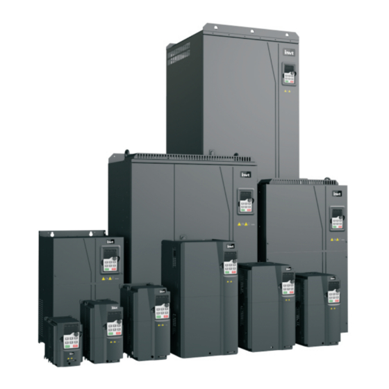
User Manuals: INVT Goodrive350-19 Series DC Drives
Manuals and User Guides for INVT Goodrive350-19 Series DC Drives. We have
3
INVT Goodrive350-19 Series DC Drives manuals available for free PDF download: Operation Manual
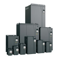
INVT Goodrive350-19 Series Operation Manual (524 pages)
Brand:
INVT
| Category:
Inverter
| Size: 18 MB
Table of Contents
Table of Contents
4
Safety Precautions
13
What this Chapter Contains
13
Safety Definition
13
Warning
13
Safety Guidelines
14
Delivery and Installation
14
Commissioning and Running
15
Maintenance and Component Replacement
16
Disposal
16
Quick Startup
17
What this Chapter Contains
17
Unpacking Inspection
17
Checking before Use
17
Environment Checking
17
Checking after Installation
18
Basic Commissioning
18
Product Overview
19
What this Chapter Contains
19
Basic Principles
19
Product Specifications
21
Product Nameplate
27
Model Designation Code
28
Product Ratings
28
Structure
30
Installation Guidelines
32
What this Chapter Contains
32
Mechanical Installation
32
Installation Environment
32
Installation Direction
33
Installation Method
34
Installing One VFD
35
Installing Multiple Vfds
35
Vertical Installation
36
Tilted Installation
37
Standard Wiring of the Main Circuit
38
Wiring Diagram of the Main Circuit
38
Main Circuit Terminal Diagram
39
Wiring Procedure for Main Circuit Terminals
43
Standard Wiring of the Control Circuit
44
Wiring Diagram of Basic Control Circuit
44
Input/Output Signal Connection Diagram
46
Control Circuit Wiring of I/O Expansion Card 2
48
Wiring Protection
49
Protecting the VFD and Input Power Cable in Case of Short Circuit
49
Protecting the Motor and Motor Cable in Case of Short Circuit
50
Protecting the Motor against Thermal Overload
50
Bypass Connection
50
Commissioning Guidelines
51
Lifting in Open-Loop Vector Control
51
Wiring
51
Commissioning Procedure
51
Macro Parameters (P90.00=1)
52
Points for Attention
53
Lifting in Closed-Loop Vector Control
54
Wiring
54
Commissioning Procedure
54
Macro Parameters (P90.00=2)
55
Points for Attention
57
Switching from Lifting in Closed-Loop Vector Control to Open-Loop Vector Control
57
Horizontal Moving
58
Wiring
58
Commissioning Procedure
59
Macro Parameters (P90.00=3)
59
Points for Attention
60
Tower Crane Slewing with Vortex
60
Wiring
60
Commissioning Procedure
61
Macro Parameters (P90.00=4)
61
Points for Attention
62
Controlling the Vortex Module through the HDO Terminal
62
Controlling the Vortex Module through the AO Terminal
64
Tower Crane Rotating Without Vortex in Space Voltage Vector Control
66
Wiring
66
Commissioning Procedure
66
Macro Parameters (P90.00=15)
66
Points for Attention
68
Conical Motor Function
68
Wiring
68
Commissioning Procedure
68
Macro Parameters (P90.00=5)
69
Points for Attention
69
Lifting in Space Voltage Vector Control
70
Wiring
70
Commissioning Procedure
70
Macro Parameters (P90.00=9)
71
Points for Attention
72
Winching in Closed-Loop Vector Control (Applicable to Lifting in Mineral Wells and Winches)
73
Wiring
73
Commissioning Procedure
74
Macro Parameters (P90.00=11)
74
Points for Attention
77
How to Use the -10-+10V Analog Operating Lever
77
Winching in Open-Loop Vector Control (Applicable to Lifting in Mineral Wells and Winches)
78
Wiring
78
Commissioning Procedure
79
Macro Parameters (P90.00=12)
79
Points for Attention
81
Electric Potentiometer
82
Wiring
82
Commissioning Procedure
82
Electric Potentiometer Commissioning Parameters
83
Brake
84
Brake Function in Space Voltage Vector Control
84
Brake Function in Open/Closed-Loop Vector Control
88
Description about Torque Verification and Brake Slip
89
Commissioning Parameters
91
Brake Function in Torque Control
93
Zero Servo
97
Zero Servo Function Description
97
Zero Servo Function Codes
99
Anti-Sway
102
Wiring
103
Commissioning Procedure of the Anti-Sway Function for Tower Cranes
103
Commissioning Procedure of the Anti-Sway Function for Factory Cranes
103
Macro Parameters
103
Master/Slave Control
106
Function Description
106
Terminal Master/Slave Function
108
Master/Slave Communication
112
Master/Slave Switchover
116
User-Defined Application Macros
119
Motor and Macro Switchover
124
Function Description
124
Description about Switching from Motor 2 to Motor 3
124
Motor and Macro Switchover Parameters
125
Motor and Macro Switchover Flowchart
127
Height Measuring
128
Commissioning Description
128
Parameters about Height Measuring
134
Temperature Measuring
137
Using PT100/PT100
137
Using KTY84
140
Basic Operation Guidelines
141
What this Chapter Contains
141
Keypad Introduction
141
Keypad Display
143
Displaying Fault Information
143
Editing Function Codes
143
Operation Procedure
144
Modifying Function Codes
144
Setting a Password for the VFD
145
Viewing VFD Status
145
Basic Operation Description
146
What this Section Describes
146
Common Commissioning Procedure
146
Vector Control
150
Space Voltage Vector Control Mode
156
Torque Control
165
Motor Parameters
170
Start/Stop Control
175
Frequency Setting
179
Analog Input
183
Analog Output
185
Digital Input
187
Digital Output
195
Simple PLC
199
Multi-Step Speed Running
201
Graded Multi-Step Speed Reference
203
Local Encoder Input
204
Commissioning Procedures for Position Control and Spindle Positioning
205
Fault Handling
211
Function Parameter List
217
What this Chapter Contains
217
P00 Group--Basic Functions
218
P01 Group--Start and Stop Control
222
P02 Group--Parameters of Motor 1
228
P03 Group--Vector Control of Motor 1
232
P04 Group--V/F Control
238
P05 Group--Input Terminals
247
P06 Group--Output Terminals
256
P07 Group--Human-Machine Interface
261
P08 Group--Enhanced Functions
269
P09 Group-- PID Control
276
P10 Group--Simple PLC and Multi-Step Speed Control
281
P11 Group--Protection Parameters
284
P12 Group--Parameters of Motor 2
291
P13 Group--SM Control
294
P14 Group--Serial Communication
296
P15 Group--Communication Expansion Card 1 Functions
298
P16 Group--Communication Expansion Card 2 Functions
298
P17 Group--Status Viewing
299
P18 Group--Status Viewing in Closed-Loop Control
304
P19 Group--Expansion Card Status Viewing
306
P20 Group--Encoder of Motor 1
307
P21 Group--Position Control
311
P22 Group--Spindle Positioning
319
P23 Group--Vector Control of Motor 2
322
P24 Group--Encoder of Motor 2
324
P25 Group--I/O Card Input Functions
328
P26 Group--I/O Card Output Functions
330
P28 Group--Master/Slave Control
332
P85 Group--Anti-Sway Control
335
P86 Group--Slewing Control
336
P89 Group--Parameters of Motor 3
338
P90 Group--Functions Special for Cranes
341
P91 Group--Functions Special for Cranes
351
P92 Group--Hoisting Protection Function Group 3
365
P93 Group--Closed-Loop Hoisting Functions
374
P94 Group--Hoisting Status Display
383
Troubleshooting
387
What this Chapter Contains
387
Indications of Alarms and Faults
387
Fault Reset
387
Fault History
387
Faults and Alarms
387
Faults and Solutions
387
Alarms and Solutions
397
Ther Status
399
Analysis on Common Faults
399
Motor Fails to Work
399
Motor Vibrates
400
Overvoltage
401
Undervoltage
401
Motor Overheating
402
VFD Overheating
403
Motor Stalls During ACC
404
Overcurrent
405
Countermeasures on Common Interference
405
Interference on Meter Switches and Sensors
405
Interference on RS485 Communication
406
Failure to Stop and Indicator Shimmering Due to Motor Cable Coupling
407
Leakage Current and Interference on RCD
408
Live Device Chassis
409
Maintenance
410
What this Chapter Contains
410
Periodical Inspection
410
Cooling Fan
413
Capacitor
414
Capacitor Reforming
414
Electrolytic Capacitor Replacement
415
Power Cable
415
Communication Protocol
416
What this Chapter Contains
416
Modbus Protocol Introduction
416
Application of Modbus
416
Rs485
416
Rtu
419
RTU Command Code and Communication Data
422
Command Code 03H, Reading N Words (Continuously up to 16 Words)
422
Command Code 06H, Writing a Word
424
Command Code 08H, Diagnosis
425
Command Code 10H, Continuous Writing
426
Data Address Definition
427
Fieldbus Scale
431
Error Message Response
432
Read/Write Operation Examples
434
Common Communication Faults
438
CW and SW Module for Port Crane Applications
439
Cws for Port Crane Applications
439
Sws for Port Crane Applications
440
Canopen/Profibus PZD Communication
440
PROFINET PZD Communication
443
Appendix A Expansion Card
446
Model Definition
446
Dimensions and Installation
452
Wiring
454
Function Description of I/O Expansion Card 1 (EC-IO501-00)
455
Communication Cards
457
Bluetooth Communication Card (EC-TX501) and WIFI Communication Card (EC-TX502)
457
PROFIBUS-DP Communication Card (EC-TX503)
459
Ethernet Communication Card (EC-TX504)
460
Canopen Communication Card (EC-TX511) and CAN Master/Slave Control
461
Communication Card (EC-TX511)
461
PROFINET Communication Card (EC-TX509)
463
CAN-NET Two-In-One Communication Card (EC-TX511B)
465
PG Expansion Cards
466
Sin/Cos PG Card (EC
466
UVW Incremental PG Card (EC
469
Resolver PG Card (EC
471
Multi-Function Incremental PG Card (EC
473
Simplified Incremental PG Card (EC
477
Simplified Incremental PG Card (EC
479
Appendix B Technical Data
483
What this Chapter Contains
483
Derated Application
483
Capacity
483
Derating
483
Grid Specifications
484
Motor Connection Data
484
Application Standards
484
CE Marking
485
EMC Compliance Declaration
485
EMC Regulations
485
VFD Category of C2
486
VFD Category of C3
486
Appendix C Dimension Drawings
487
What this Chapter Contains
487
LED Keypad
487
Structure Diagram
487
Keypad Mounting Bracket
487
LCD Keypad
488
Structure Diagram
488
Keypad Mounting Bracket
488
VFD Structure
489
Dimensions of AC 3PH 380V (-15%)-440V (+10%)
490
Wall Mounting Dimensions
490
Flange Installation Dimensions
492
Floor Installation Dimensions
494
Dimensions of AC 3PH 520V (-15%)-690V (+10%)
495
Wall Mounting Dimensions
495
Flange Installation Dimensions
496
Floor Installation Dimensions
497
Appendix D Optional Peripheral Accessories
499
What this Chapter Contains
499
Wiring of Peripheral Accessories
499
LCD Keypad
500
Power Supply
501
Cable
501
Powe Cable
501
Control Cables
502
Recommended Cable Size
503
Cable Arrangement
505
Insulation Inspection
506
Breaker and Electromagnetic Contactor
506
Reactor
508
Filters
511
Filter Model Description
512
Filter Model Selection
512
Braking System
514
Braking Component Selection
514
Braking Resistor Cable Selection
518
Braking Resistor Installation
518
Regenerative Feedback Unit
519
Installation Wiring for Regenerative Feedback Unit
519
Regenerative Feedback Unit Model Selection
519
Appendix E STO Function Description
521
STO Function Logic Table
521
STO Channel Delay Description
521
STO Function Installation Checklist
522
Appendix F Further Information
523
Product and Service Queries
523
Feedback on INVT VFD Manuals
523
Documents on the Internet
523
Advertisement
INVT Goodrive350-19 Series Operation Manual (533 pages)
VFD for Crane
Brand:
INVT
| Category:
DC Drives
| Size: 33 MB
Table of Contents
Table of Contents
5
Safety Precautions
13
What this Chapter Contains
13
Safety Definition
13
Warning Symbols
13
Safety Guidelines
14
Delivery and Installation
14
Commissioning and Running
15
Maintenance and Component Replacement
16
Disposal
16
Quick Startup
17
What this Chapter Contains
17
Unpacking Inspection
17
Checking before Use
17
Environment Checking
17
Checking after Installation
18
Basic Commissioning
18
Product Overview
20
What this Chapter Contains
20
Basic Principles
20
Product Specifications
22
Product Nameplate
29
Model Designation Code
29
Product Ratings
30
Structure
33
Installation Guidelines
34
What this Chapter Contains
34
Mechanical Installation
34
Installation Environment
34
Installation Direction
35
Installation Method
36
Installing One VFD
37
Multiple-VFD Installation
37
Vertical Installation
38
Tilted Installation
39
Standard Wiring of the Main Circuit
40
Main Circuit Wiring Diagram
40
Main Circuit Terminal Diagram
41
Wiring Procedure for Main Circuit Terminals
45
Standard Wiring of the Control Circuit
46
Wiring Diagram of Basic Control Circuit
46
Input/Output Signal Connection Diagram
48
Control Circuit Wiring of I/O Expansion Card 2
50
Wiring Protection
52
Protecting the VFD and Input Power Cable in Case of Short Circuit
52
Protecting the Motor and Motor Cable in Case of Short Circuit
52
Protecting the Motor against Thermal Overload
52
Bypass Connection
52
Commissioning Guidelines
53
Lifting
53
Commissioning the Mechanical Holding Brake Function (P90.04=1)
53
Commissioning Steel Wire Rope (such as in a Tower Crane) Lifting Applications
66
Commissioning Gear-Rack Lifting Applications (such as in Elevators and Hoists)
71
Commissioning Lifting Applications in Mine Hoists, Winches, and Drawworks
76
Commissioning the Zero Servo Function
82
Height Measuring
86
Commissioning the Conical Motor Function
97
Commissioning Horizontal Moving
99
Wiring
99
Commissioning Procedure
99
Horizontal Moving Application Macro Parameters (P90.00=3)
99
Points for Attention
100
Commissioning Anti-Sway
101
Commissioning Tower Crane Slewing
107
Wiring
107
Commissioning Tower Crane Slewing Without Using an Eddy Current Controller
107
Commissioning Tower Crane Slewing that Uses an Eddy Current Controller
111
Commissioning the Electric Potentiometer
116
Wiring
116
Commissioning Procedure
116
Electric Potentiometer Commissioning Parameters
117
Master/Slave Control
118
Function Description
118
Terminal Master/Slave Function
120
Master/Slave Communication
124
Master/Slave Switchover
129
User-Defined Application Macros
131
Motor and Macro Switchover
136
Description about Switching from Motor 2 to Motor 3
137
Motor and Macro Switchover Parameters
137
Terminal-Based Motor and Macro Switchover Flowchart
139
Shortcut Multi-Motor Speed Control Mode Switchover
140
PG Card Switchover
141
Temperature Measuring
142
Using PT100/PT1000
142
Using KTY84
145
Using PTC
146
Basic Operation Guidelines
148
What this Chapter Contains
148
LED Keypad Introduction
148
LED Keypad Display
150
Displaying Fault Information
150
Editing Function Codes
150
Operating the VFD through the LED Keypad
151
Modifying Function Codes
151
Setting a Password for the VFD
152
Viewing VFD Status
153
Basic Operation Description
153
What this Section Describes
153
Common Commissioning Procedure
153
Vector Control
153
Space Voltage Vector Control Mode
153
Torque Control
153
Motor Parameters
153
Start/Stop Control
153
Frequency Setting
153
Multi-Step Speed Running
154
Graded Multi-Step Speed Reference
156
Local Encoder Input
157
Position Control
157
Fault Handling
157
Function Parameters
158
What this Chapter Contains
158
Function Parameter List
158
Group P00-Basic Functions
159
Group P01-Start and Stop Control
163
Group P02-Parameters of Motor 1
170
Group P03--Vector Control of Motor 1
173
Group P04-V/F Control
180
Group P05-Input Terminal Functions
189
Group P06-Output Terminal Functions
198
Group P07-Human-Machine Interface
204
Group P08-Enhanced Functions
211
Group P09-PID Control
221
Group P10-Simple PLC and Multi-Step Speed Control
225
Group P11-Protection Parameters
229
Group P12--Parameters of Motor 2
239
Group P13-SM Control
241
Group P14-Serial Communication
243
Group P15--Communication Expansion Card 1 Functions
248
Group P16--Communication Expansion Card 2 Functions
253
Group P17-Status Viewing
262
Group P18-Status Viewing in Closed-Loop Control
267
Group P19-Expansion Card Status Viewing
270
Group P20--Encoder of Motor 1
272
Group P21--Position Control
276
Actual Position
282
Group P23--Vector Control of Motor 2
286
Group P24--Encoder of Motor 2
288
Group P25--I/O Card Input Functions
292
Group P26--I/O Card Output Functions
295
Group P27--Programmable Expansion Card Functions
298
Group P28--Master/Slave Control
301
Group P85--Anti-Sway Control
304
Group P86-Slewing Control
305
Group P89--Parameters of Motor 3
309
Group P90--Functions Special for Cranes
311
Group P91-Functions Special for Cranes
321
Group P92-Hoisting Protection Function Group 3
335
Group P93-Closed-Loop Hoisting Functions
346
Group P94--Hoisting Status Display
355
Troubleshooting
360
What this Chapter Contains
360
Indications of Alarms and Faults
360
Fault Reset
360
Fault History
360
Faults and Solutions
360
Alarms and Solutions
371
Other Status
373
Analysis on Common Faults
374
Motor Fails to Work
374
Motor Vibrates
375
Overvoltage
376
Undervoltage
376
Motor Overheating
377
VFD Overheating
378
Motor Stalls During ACC
379
Overcurrent
380
Countermeasures on Common Interference
381
Interference on Meter Switches and Sensors
381
Interference on RS485 Communication
382
Failure to Stop and Indicator Shimmering Due to Motor Cable Coupling
383
Leakage Current and Interference on RCD
383
Live Device Housing
384
Maintenance
386
What this Chapter Contains
386
Periodical Inspection
386
Cooling Fan
388
Capacitor
389
Capacitor Reforming
389
Electrolytic Capacitor Replacement
390
Power Cable
391
Communication Protocol
392
What this Chapter Contains
392
Modbus Protocol Introduction
392
Application of Modbus
392
Rs485
392
RTU Mode
395
RTU Command Code and Communication Data
398
Command Code 03H, Reading N Words (Continuously up to 16 Words)
398
Command Code 06H, Writing a Word
400
Command Code 10H, Continuous Writing
401
Data Address Definition
402
Fieldbus Scale
406
Error Message Response
407
Read/Write Operation Examples
409
Common Communication Faults
413
Short Description of Communication PZD
414
Dedicated CW (P16.72 Ones Place=1 or 3)
414
Dedicated SW (P16.72 Ones Place=1 or 3)
415
Short Description of Canopen/Profibus DP Communication PZD
416
Short Description of Profinet/Ethernet IP Communication PZD
420
Appendix A Expansion Card
422
Model Definition
422
Dimensions and Installation
431
Wiring
433
IO Card (EC-IO501-00)
434
Communication Cards
436
WIFI Communication Card (EC-TX502)
436
PROFIBUS-DP Communication Card (EC-TX503D)
438
Ethernet Communication Card (EC-TX504)
440
Canopen/Can Master/Slave Control Communication Card (EC-TX505D)
440
PROFINET Communication Card (EC-TX509C)
442
Ethernet IP Communication Card (EC-TX510)
444
CAN-NET Two-In-One Communication Card (EC-TX511B)
445
Modbus TCP Communication Card (EC-TX515)
446
Ethercat Communication Card (EC-TX508)
447
PG Expansion Cards
451
Sin/Cos PG Card (EC
451
UVW Incremental PG Card (EC
453
Resolver PG Card (EC
456
Multi-Function Incremental PG Card (EC
458
Simplified Incremental PG Card (EC-PG507-12B)
462
Simplified Incremental PG Card (EC
463
Absolute Encoder SSI Communication PG Card (EC-PG508-05B)
467
Iot Expansion Card
471
Expansion Card (EC-IC502-2)
471
Power Supply Expansion Cards
472
Power Supply Expansion Card (EC-PS501-24)
472
Appendix B Technical Data
473
What this Chapter Contains
473
Derated Application
473
Capacity
473
Derating
473
Grid Specifications
474
Motor Connection Data
474
Application Standards
474
CE Marking
475
EMC Compliance Declaration
475
EMC Regulations
475
VFD Category of C2
476
VFD Category of C3
476
Appendix C Dimension Drawings
477
What this Chapter Contains
477
LED Keypad
477
Structure Diagram
477
Keypad Mounting Bracket
477
LCD Keypad
478
Structure Diagram
478
Keypad Mounting Bracket
478
VFD Structure
479
Dimensions of AC 3PH 380V (-15%)-440V (+10%)
480
Wall Mounting Dimensions
480
Flange Mounting Dimensions
482
Floor Mounting Dimensions
484
Dimensions of AC 3PH 520V (-15%)-690V (+10%)
485
Wall-Mounting Dimensions
485
Flange Mounting Dimensions
486
Floor Mounting Dimensions
487
Appendix D Optional Peripheral Accessories
489
What this Chapter Contains
489
External Wiring
489
LCD Keypad
490
LCD Keypad Display
494
Operating the VFD through the LCD Keypad
496
Power Supply
509
Cable
509
Power Cable
509
Control Cable
510
Recommended Cable Size
511
Cable Arrangement
513
Insulation Inspection
513
Breaker and Electromagnetic Contactor
513
Reactor
515
Filter
519
Filter Model Description
520
Filter Model Selection
521
Braking System
522
Braking Component Selection
522
Braking Resistor Cable Selection
526
Braking Resistor Installation
526
Regenerative Unit
527
Regenerative Unit Installation and Wiring
527
Appendix E STO Function Description
530
STO Function Logic Table
530
STO Channel Delay Description
530
STO Function Installation Checklist
531
Appendix F Further Information
532
Product and Service Queries
532
Feedback on INVT VFD Manuals
532
Documents on the Internet
532
INVT Goodrive350-19 Series Operation Manual (540 pages)
Brand:
INVT
| Category:
DC Drives
| Size: 16 MB
Table of Contents
Table of Contents
5
1 Safety Precautions
8
What this Chapter Contains
8
Safety Definition
8
Warning Symbols
8
Safety Guidelines
9
2 Quick Startup
12
What this Chapter Contains
12
Unpacking Inspection
12
Checking before Use
12
Environment Checking
12
Checking after Installation
13
Basic Commissioning
13
3 Product Overview
14
What this Chapter Contains
14
Basic Principle
14
Product Specifications
16
Product Nameplate
22
Model Designation Code
22
Product Ratings
23
Structural Diagram
25
4 Installing
26
What this Chapter Contains
26
Mechanical Installation
26
Main Circuit Standard Wiring
32
Standard Wiring of Control Circuit
39
Wiring Protection
44
5 Commissioning
46
Commissioning Lifting in Open-Loop Vector Control
46
Commissioning Lifting in Closed-Loop Vector Control
50
Commissioning Horizontal Moving
54
Commissioning Tower Crane Rotating
56
Commissioning the Conical Motor Function
58
Commissioning Lifting in Space Voltage Vector Control
60
Commissioning Winching in Closed-Loop Vector Control (Applicable to Lifting in Mineral Wells and Winches)
63
Commissioning Winching in Open-Loop Vector Control
68
Winches)
68
Commissioning the Brake Function
72
Commissioning the Master/Slave Function
83
Motor and Macro Switchover
91
Measuring Heights
100
6 Operating
111
What this Chapter Contains
111
Keypad
111
Keypad Display
113
Operations on Keypad
114
Basic Operation Instruction
116
7 Function Parameter List
208
What this Chapter Contains
208
8 Troubleshooting
395
What this Chapter Contains
395
Indications of Alarms and Faults
395
Fault Reset
395
Fault History
395
VFD Faults and Solutions
395
Analysis on Common Faults
409
Countermeasures on Common Interference
416
9 Maintenance
421
What this Chapter Contains
421
Periodical Inspection
421
Cooling Fan
424
Capacitor
425
Power Cable
426
10 Communication Protocols
427
What this Chapter Contains
427
MODBUS Protocol Introduction
427
Application of Modbus
427
RTU Command Code and Communication Data
434
Common Communication Faults
452
Appendix A Extension Cards
453
Model Description
453
Dimensions and Installation
459
Wiring
461
Function Description of I/O Extension Card 1 (EC-IO501-00)
462
Function Description of Communication Cards
464
Function Description of PG Extension Cards
474
Appendix B Technical Data
493
What this Chapter Contains
493
Derated Application
493
Grid Specifications
494
Motor Connection Data
494
Application Standards
495
EMC Regulations
496
Appendix C Dimensional Drawings
498
What this Chapter Contains
498
LED Keypad
498
LCD Keypad
499
VFD Structure
500
AC 3PH 380V(-15%)-440V(+10%) VFD Dimensions
501
AC 3PH 520V(-15%)-690V(+10%) VFD Dimensions
508
Appendix D Optional Peripheral Accessories
512
What this Chapter Contains
512
Wiring of Peripheral Accessories
512
LCD Keypad
514
Power Supply
514
Cables
514
Breakers and Electromagnetic Contactors
520
Reactors
522
Filters
525
Braking System
528
Regenerative Feedback Unit
534
Appendix E STO Function Description
536
STO Function Logic Table
536
STO Channel Delay Description
536
STO Function Installation Checklist
537
Appendix F Further Information
539
Product and Service Queries
539
Feedback on INVT VFD Manuals
539
Documents on the Internet
539
Advertisement
Advertisement
Related Products
INVT Goodrive300-21 Series
INVT Goodrive100-PV Series
INVT Goodrive20-EU VFD Series
INVT Goodrive300-01A Series
INVT Goodrive200A Series
INVT Goodrive20-UL VFD Series
INVT Goodrive800 Pro Series
INVT Goodrive350A Series
INVT Goodrive300 Series
INVT GD3000-11-110G-12
INVT Categories
Inverter
DC Drives
Servo Drives
Controller
UPS
More INVT Manuals
Login
Sign In
OR
Sign in with Facebook
Sign in with Google
Upload manual
Upload from disk
Upload from URL