Mitsubishi Electric MELSEC iQ-R Series User Manual
Master/local module
Hide thumbs
Also See for MELSEC iQ-R Series:
- Programming manual (2110 pages) ,
- User manual (760 pages) ,
- Reference manual (498 pages)
Table of Contents
Advertisement
Quick Links
Advertisement
Table of Contents
Troubleshooting

Related Manuals for Mitsubishi Electric MELSEC iQ-R Series


Summary of Contents for Mitsubishi Electric MELSEC iQ-R Series
- Page 1 MELSEC iQ-R CC-Link IE TSN Plus Master/Local Module User's Manual -RJ71GN11-EIP...
-
Page 3: Safety Precautions
SAFETY PRECAUTIONS (Read these precautions before using this product.) Before using this product, please read this manual and the relevant manuals carefully and pay full attention to safety to handle the product correctly. The precautions given in this manual are concerned with this product only. For the safety precautions of the programmable controller system, refer to the MELSEC iQ-R Module Configuration Manual. - Page 4 [Design Precautions] WARNING ● Configure safety circuits external to the programmable controller to ensure that the entire system operates safely even when a fault occurs in the external power supply or the programmable controller. Failure to do so may result in an accident due to an incorrect output or malfunction. (1) Emergency stop circuits, protection circuits, and protective interlock circuits for conflicting operations (such as forward/reverse rotations or upper/lower limit positioning) must be configured external to the programmable controller.
- Page 5 [Design Precautions] WARNING ● When connecting an external device with a CPU module or intelligent function module to modify data of a running programmable controller, configure an interlock circuit in the program to ensure that the entire system will always operate safely. For other forms of control (such as program modification, parameter change, forced output, or operating status change) of a running programmable controller, read the relevant manuals carefully and ensure that the operation is safe before proceeding.
- Page 6 [Design Precautions] CAUTION ● Do not install the control lines or communication cables together with the main circuit lines or power cables. Doing so may result in malfunction due to electromagnetic interference. Keep a distance of 100mm or more between those cables. ●...
- Page 7 Also, attach an extension connector protective cover to each unused extension cable connector as necessary. Directly touching any conductive parts of the connectors while power is on may result in electric shock. *1 For details, please consult your local Mitsubishi Electric representative.
- Page 8 [Wiring Precautions] CAUTION ● Individually ground the FG and LG terminals of the programmable controller with a ground resistance of 100 ohms or less. Failure to do so may result in electric shock or malfunction. ● Use applicable solderless terminals and tighten them within the specified torque range. If any spade solderless terminal is used, it may be disconnected when the terminal screw comes loose, resulting in failure.
- Page 9 [Startup and Maintenance Precautions] WARNING ● Do not touch any terminal while power is on. Doing so will cause electric shock or malfunction. ● Correctly connect the battery connector. Do not charge, disassemble, heat, short-circuit, solder, or throw the battery into the fire. Also, do not expose it to liquid or strong shock. Doing so will cause the battery to produce heat, explode, ignite, or leak, resulting in injury and fire.
- Page 10 For details on how to eliminate static electricity from the module, refer to the following. Antistatic Precautions Before Using MELSEC iQ-R Series Products (FA-A-0368) ● Use a clean and dry cloth to wipe off dirt on the module.
- Page 11 [Transportation Precautions] CAUTION ● When transporting lithium batteries, follow the transportation regulations. For details on the regulated models, refer to the MELSEC iQ-R Module Configuration Manual. ● The halogens (such as fluorine, chlorine, bromine, and iodine), which are contained in a fumigant used for disinfection and pest control of wood packaging materials, may cause failure of the product.
-
Page 12: Conditions Of Use For The Product
Notwithstanding the above restrictions, Mitsubishi Electric may in its sole discretion, authorize use of the PRODUCT in one or more of the Prohibited Applications, provided that the usage of the PRODUCT is limited only for the specific applications agreed to by Mitsubishi Electric and provided further that no special quality assurance or fail-safe, redundant or other safety features which exceed the general specifications of the PRODUCTs are required. -
Page 13: Introduction
Before using this product, please read this manual and the relevant manuals carefully and develop familiarity with the functions and performance of the MELSEC iQ-R series programmable controller to handle the product correctly. When applying the program examples provided in this manual to an actual system, ensure the applicability and confirm that it will not cause system control problems. -
Page 14: Table Of Contents
CONTENTS SAFETY PRECAUTIONS ..............1 CONDITIONS OF USE FOR THE PRODUCT . - Page 15 CHAPTER 7 WIRING CHAPTER 8 PARAMETER SETTINGS Parameter Settings for CC-Link IE TSN............73 Procedure for setting parameters .
- Page 16 CC-Link IE TSN Network Synchronous Communication Function....... 200 Others ................209 Reserved station setting .
- Page 17 12.4 Message Communication Function (Server) ..........288 UCMM message communications (server) .
- Page 18 CHAPTER 16 CHECKING THE MODULE STATUS 16.1 Module Diagnostics..............368 Module Communication Test .
- Page 19 Appendix 9 Port Number ..............550 Appendix 10External Dimensions .
-
Page 20: Relevant Manuals
• Installation For details, refer to the following. MELSEC iQ-R Module Configuration Manual e-Manual refers to the Mitsubishi Electric FA electronic book manuals that can be browsed using a dedicated tool. e-Manual has the following features: • Required information can be cross-searched in multiple manuals. -
Page 21: Terms
TERMS Unless otherwise specified, this manual uses the following terms. Term Description Adapter For EtherNet/IP communications, an EtherNet/IP device that has only the function by which a connection is opened (target function) Buffer memory Memory in an intelligent function module to store data such as setting values and monitor values. For CPU modules, it refers to memory to store data such as setting values and monitor values of the Ethernet function, or data used for data communication of the multiple CPU system function. - Page 22 Term Description Reserved address An IP address reserved for special purposes, defined by RFC 6890. This IP address cannot be used when the programmable controller is connected via the global IP network. RnENCPU (network part) A module on the right-hand side of the RnENCPU ( MELSEC iQ-R Ethernet/CC-Link IE User's Manual (Startup)) Routing A process of selecting paths for communication with other networks.
-
Page 23: Generic Terms And Abbreviations
An abbreviation for GP.CONOPEN Consumer Tag Another name for the consumed tag CPU module A generic term for the MELSEC iQ-R series CPU modules Data link A generic term for cyclic transmission and transient transmission DHCP An abbreviation for Dynamic Host Configuration Protocol. A protocol used for automatically assigning the information required for the network such as an IP address. - Page 24 Generic term/abbreviation Description REMFRD An abbreviation for the JP.REMFRD REMFRDIP An abbreviation for the GP.REMFRDIP REMFRIP An abbreviation for the GP.REMFRIP REMTO A generic term for the JP.REMTO and ZP.REMTO REMTOD An abbreviation for the JP.REMTOD REMTODIP An abbreviation for the GP.REMTODIP REMTOIP An abbreviation for the GP.REMTOIP A generic term for the J.REQ, JP.REQ, G.REQ, and GP.REQ...
-
Page 25: Part 1 Overview
PART 1 OVERVIEW This part consists of the following chapters. 1 WHAT CAN BE PERFORMED WITH THIS MODULE 2 CC-Link IE TSN SYSTEM CONFIGURATION 3 EtherNet/IP SYSTEM CONFIGURATION... -
Page 26: Chapter 1 What Can Be Performed With This Module
WHAT CAN BE PERFORMED WITH THIS MODULE The CC-Link IE TSN Plus module has the following features. Communicating with two networks with a single module The CC-Link IE TSN Plus module can communicate with the following networks. • CC-Link IE TSN ... - Page 27 Number of connectable networks In CC-Link IE TSN communications, a total of 239 networks can be connected between Mitsubishi Electric programmable controller network modules by relay stations , regardless of the network type . (Relaying via EtherNet/IP cannot be performed.)
-
Page 28: Chapter 2 Cc-Link Ie Tsn System Configuration
CC-Link IE TSN SYSTEM CONFIGURATION CC-Link IE TSN is configured using Ethernet cables. ( Page 71 Ethernet cable) (1) CC-Link IE TSN Plus module (2) Inverter device (3) Remote I/O module (4) Ethernet device (such as a vision sensor) Precautions •... - Page 29 CC-Link IE TSN Class Setting From "Connection Device Information" under "Basic Settings" of the engineering tool, select either of the following items according to devices to be connected. Connected device System configuration Supported standard information CC-Link IE TSN Class B Select this if the system is to be configured without connecting the CC-Link IE TSN Class A device.
-
Page 30: Structure Of Cc-Link Ie Tsn Class B Devices And Ethernet Devices
Structure of CC-Link IE TSN Class B Devices and Ethernet Devices This section describes the system configuration when "Connection Device Information" under "Basic Settings" of the engineering tool is set to "CC-Link IE TSN Class B Only". When "Connection Device Information" under "Basic Settings" of the master station is set to "CC-Link IE TSN Class B Only", up to 121 devices (1 master station and 120 slave stations) can be connected. -
Page 31: Structure Of Unicast Mode
Structure of unicast mode This mode indicates the availability of connection with a network configuration device when "Communication Mode" under "Application Settings" is set to "Unicast". When the communication speed for the master station is set to 1Gbps This mode indicates the availability of connection with a network configuration device when "Communication Speed" of the master station is set to "1Gbps". - Page 32 When the communication speed for the master station is set to 100Mbps This mode indicates the availability of connection with a network configuration device when "Communication Speed" of the master station set to "100Mbps". : Connection available, : Connection available via a switching hub, : Connection not available S: TSN hub available H: General-purpose hub available Device on the master station...
-
Page 33: Structure Of Multicast Mode
Structure of multicast mode This mode indicates the availability of connection with a network configuration device when "Communication Mode" under "Application Settings" is set to "Multicast". When the communication speed for the master station is set to 1Gbps This mode indicates the availability of connection with a network configuration device when "Communication Speed" of the master station is set to "1Gbps". - Page 34 When the communication speed for the master station is set to 100Mbps This mode indicates the availability of connection with a network configuration device when "Communication Speed" of the master station set to "100Mbps". : Connection available, : Connection available via a switching hub, : Connection not available S: TSN hub available H: General-purpose hub available Device on the master station...
-
Page 35: Structure With Modules On Cc-Link Ie Tsn Only
Structure with modules on CC-Link IE TSN only This section describes the system configurations when the system consists only of modules with CC-Link IE TSN (master station, local stations, remote stations) of CC-Link IE TSN Class B devices. Item Network topology Reference Structure with CC-Link IE TSN modules only Line topology... - Page 36 Connection with modules on CC-Link IE TSN with a communication speed of 100Mbps This section describes the network topology when "Communication Speed" under "Application Settings" is set to "100Mbps". ■Line topology The network is configured in a line topology. • Adjust the communication speed of each module. •...
- Page 37 • When "Communication Mode" is set to "Multicast" and "Communication Speed" of the master station is set to "1Gbps", communication may not be possible depending on the type of the device if slave stations with different communication speeds of 1Gbps and 100Mbps coexist on the end side via the switching hub. The communication will be enabled by configuring settings with the TSN hub so that the multicast frame (with multicast MAC address 09:00:70:00:10:02 and 09:00:70:00:10:05) will not be transferred to the slave station with 100Mbps.
-
Page 38: Structure With Modules On Cc-Link Ie Tsn And Ethernet Devices
Structure with modules on CC-Link IE TSN and Ethernet devices Connection with modules on CC-Link IE TSN and Ethernet devices This section describes the system configurations when the system consists of modules with CC-Link IE TSN (master station, local stations, remote stations) of CC-Link IE TSN Class B devices and Ethernet devices. Network topology Reference Line topology... - Page 39 ■Coexistence of line and star topologies Line and star topologies can be mixed in the same network configuration. • Connect Ethernet devices to the end of the network. General-purpose hub or TSN hub No.0 No.1 No.0: Master station (CC-Link IE TSN Plus module) No.1: Remote station (1), (2): Ethernet device 2 CC-Link IE TSN SYSTEM CONFIGURATION...
-
Page 40: Structure Of Cc-Link Ie Tsn Class B/A Devices And Ethernet Devices
Structure of CC-Link IE TSN Class B/A Devices and Ethernet Devices The following diagram shows the system configuration under the conditions below: • CC-Link IE TSN Plus module supports protocol version 2.0. • CC-Link IE TSN Plus module is protocol version 2.0 only. •... -
Page 41: Structure Of Unicast Mode
Structure of unicast mode This mode indicates the availability of connection with a network configuration device when "Communication Mode" under "Application Settings" is set to "Unicast". When the communication speed for the master station is set to 1Gbps This mode indicates the availability of connection with a network configuration device when "Communication Speed" of the master station is set to "1Gbps". - Page 42 When the communication speed for the master station is set to 100Mbps This mode indicates the availability of connection with a network configuration device when "Communication Speed" of the master station set to "100Mbps". : Connection available, : Connection available via a switching hub, : Connection not available S: TSN hub available H: General-purpose hub available Device on the master...
-
Page 43: Structure Of Multicast Mode
Structure of multicast mode This mode indicates the availability of connection with a network configuration device when "Communication Mode" under "Application Settings" is set to "Multicast". When the communication speed for the master station is set to 1Gbps This mode indicates the availability of connection with a network configuration device when "Communication Speed" of the master station is set to "1Gbps". - Page 44 When the communication speed for the master station is set to 100Mbps This mode indicates the availability of connection with a network configuration device when "Communication Speed" of the master station set to "100Mbps". : Connection available, : Connection available via a switching hub, : Connection not available S: TSN hub available H: General-purpose hub available Device on the master...
-
Page 45: Structure With Modules On Cc-Link Ie Tsn
Structure with modules on CC-Link IE TSN This section describes the system configurations when CC-Link IE TSN Class B devices and CC-Link IE TSN Class A devices coexist, or when the system consists of modules with CC-Link IE TSN (master station, local stations, remote stations) of CC- Link IE TSN Class A devices only. - Page 46 ■Star topology The network is configured in a star topology via a switching hub. • When connecting CC-Link IE TSN Class B devices in a star topology, use a TSN hub. No.0 Class B No.2 Class B TSN HUB No.1 No.3 Class B Class B...
- Page 47 ■Coexistence of line and star topologies Line and star topologies can be mixed according to the following connection requirements. • When connecting CC-Link IE TSN Class B devices in a star topology, use a TSN hub. No.0 No.1 Class B Class B No.2 No.3...
- Page 48 • In a configuration of mixture of CC-Link IE TSN Class B/A, CC-Link IE TSN Class A devices can be connected from a TSN hub between CC-Link IE TSN Class B devices. No.0 No.1 Class B Class B No.2 No.3 TSN HUB Class B TSN HUB...
- Page 49 Precautions In a system configuration of mixture of CC-Link IE TSN Class B/A, set whether to use a TSN hub in "TSN HUB Setting" in "Connection Device Information" under "Basic Settings". If the presence/absence of a TSN hub in the system configuration differs from the "TSN HUB Setting", the CC-Link IE TSN Class A device may not perform data link.
- Page 50 Connection with modules on CC-Link IE TSN with a communication speed of 100Mbps This section describes the network topology when "Communication Speed" under "Application Settings" is set to "100Mbps". ■Line topology The network is configured in a line topology. • Adjust the communication speed of the module. •...
- Page 51 • When "Communication Mode" is set to "Multicast" and the communication speed of the master station is 1Gbps, communication may not be possible depending on the type of the device if slave stations with different communication speeds of 1Gbps and 100Mbps coexist on the end side via the switching hub. The communication will be enabled by configuring settings with the switching hub so that the multicast frame (with multicast MAC address 09:00:70:00:10:02 and 09:00:70:00:10:05) will not be transferred to the port of the slave station with 100Mbps.
- Page 52 ■Coexistence of line and star topologies Line and star topologies can be mixed in the same network configuration. • When the master station with a communication speed of 1Gbps and a local station and remote station with a communication speed of 100Mbps exist in the structure, set "Communication Period Setting" to "Low-Speed" for the local station and remote station with a communication speed of 100Mbps.
-
Page 53: Structure With Modules On Cc-Link Ie Tsn And Ethernet Devices
Structure with modules on CC-Link IE TSN and Ethernet devices Connection with modules on CC-Link IE TSN and Ethernet devices This section describes the system configurations when CC-Link IE TSN Class B devices and CC-Link IE TSN Class A devices coexist, or when the system consists of modules with CC-Link IE TSN (master station, local stations, remote stations) of CC- Link IE TSN Class A devices only and Ethernet devices. - Page 54 ■Coexistence of line and star topologies Line and star topologies can be mixed according to the following connection requirements. • Connect Ethernet devices at the end of line topology. • When connecting the Ethernet device in a star topology, connect the Ethernet device to a switching hub. No.2 No.0 No.1...
-
Page 55: Structure Of Cc-Link Ie Tsn And Cc-Link Ie Field Network
Structure of CC-Link IE TSN and CC-Link IE Field Network Set the CC-Link IE TSN Plus module and CC-Link IE Field Network master/local-equipped modules to different network numbers, and mount the master station of each network to the same base unit. Connect Ethernet devices to the end of the network. -
Page 56: Structure When Cc-Link Ie Tsn Communication Software Is Used
Structure When CC-Link IE TSN Communication Software Is Used Connection specifications The system configuration of CC-Link IE TSN Communication Software corresponds to that of a local station (CC-Link IE TSN Class A). ( Page 552 Structure of CC-Link IE TSN Class B/A Devices (Protocol Version 1.0 Only) and Ethernet Devices) CC-Link IE TSN Communication Software can be connected to a port of the CC-Link IE TSN Class B device (supporting CC- Link IE TSN). - Page 57 ■Coexistence of line and star topologies Connect a cable for CC-Link IE TSN Communication Software to a port of the TSN hub or the end of the network. No.0 TSN HUB No.2 No.1 No.3 No.0: Master station (CC-Link IE TSN Plus module) No.1: Local station No.2, No.3: Remote station (1) CC-Link IE TSN Communication Software...
-
Page 58: Precautions For System Configuration
Precautions for System Configuration Devices connected to the same network Do not connect the devices as described below. Doing so may cause the disconnection of all stations. • A module on CC-Link IE TSN and a device having different network types (such as CC-Link IE Controller Network or CC- Link IE Field Network) other than an Ethernet device are connected to the same network. -
Page 59: Chapter 3 Ethernet/Ip System Configuration
EtherNet/IP SYSTEM CONFIGURATION EtherNet/IP Configuration EtherNet/IP consists of the CC-Link IE TSN Plus module (1) and EtherNet/IP devices (2). Connect them using a switching hub and Ethernet cables. Ring topology is not possible. Scanner and adapter In EtherNet/IP, station types are separated into scanner and adapter. Station type Description Scanner... -
Page 60: Available Software Packages
EtherNet/IP configuration tool. ■EDS file Download the EDS file of the CC-Link IE TSN Plus module from Mitsubishi Electric FA Global Site. Obtain the EDS file of the EtherNet/IP device to be connected from the website of each device manufacturer. -
Page 61: Part 2 Specifications
PART 2 SPECIFICATIONS This part consists of the following chapter. 4 PERFORMANCE SPECIFICATIONS... -
Page 62: Chapter 4 Performance Specifications
PERFORMANCE SPECIFICATIONS This chapter describes the performance specifications of the CC-Link IE TSN Plus module. Performance Specifications of CC-Link IE TSN The following table lists the performance specifications of CC-Link IE TSN for the CC-Link IE TSN Plus module. Item Description Maximum number of link points per network 16K points (16384 points, 2K bytes) -
Page 63: Performance Specifications Of Ethernet
Performance Specifications of Ethernet The following table lists the performance specifications of Ethernet for the CC-Link IE TSN Plus module. Item Description Connection to P1 Connection to P2 Transmission specifications Data transmission speed • 1Gbps • 100Mbps Communication mode 1000BASE-T Full-duplex 100BASE-TX Full-duplex... -
Page 64: Performance Specifications Of Ethernet/Ip
Performance Specifications of EtherNet/IP The following table lists the performance specifications of EtherNet/IP for the CC-Link IE TSN Plus module. Item Description EtherNet/IP Class1 Communication format Instance communications, tag communications communications communications Number of connections • Instance communications: 256 • Tag communications: 256 Communication data size 1444 bytes (per connection) Connection type... - Page 65 Combinations of number of connections The following table lists the total number of connections consumed by various combinations with each communication. : Consumed, : Not consumed Item Number of connections Number of client Number of server that can be set simultaneous executions simultaneous executions Class1...
-
Page 66: Hardware Specifications
Hardware Specifications The following table shows the hardware specifications of the CC-Link IE TSN Plus module. Item Description Number of occupied I/O points 32 points (I/O assignment: Intelligent 32 points) Internal current consumption (5VDC) 1.54A External dimensions Height 106mm (Base unit mounting side: 98mm) Width 27.8mm Depth... -
Page 67: Part 3 Settings
PART 3 SETTINGS This part consists of the following chapters. 5 PART NAMES 6 PROCEDURES BEFORE OPERATION 7 WIRING 8 PARAMETER SETTINGS... -
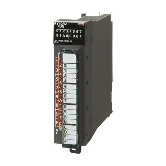
Page 68: Chapter 5 Part Names
PART NAMES This chapter describes the part names of the CC-Link IE TSN Plus module. Name Description RUN LED Indicates the operating status. • On: Normal operation • Off: Error ( Page 364 When the RUN LED turns off) ERR LED Indicates the error status of the module. - Page 69 Name Description Port connector for network. Connect an Ethernet cable. For wiring methods and wiring precautions, refer to the following. Page 70 WIRING L ER LED Indicates the port status. (The LED is always off in offline mode.) • On: Abnormal data being received ( Page 366 When the L ER LED turns on) •...
-
Page 70: Chapter 6 Procedures Before Operation
PROCEDURES BEFORE OPERATION This chapter describes the procedures before operation. Procedures for using CC-Link IE TSN Network configuration Configure the system and set the parameters which are required for start-up. • Wiring ( Page 70 WIRING) • Parameter settings ( Page 73 Parameter Settings for CC-Link IE TSN) Network diagnostics Use CC-Link IE TSN/CC-Link IE Field diagnostics to check that cables are connected properly and that modules are communicating correctly with the set parameters. - Page 71 MEMO 6 PROCEDURES BEFORE OPERATION...
-
Page 72: Chapter 7 Wiring
WIRING This chapter describes the wiring methods, wiring products, and wiring precautions when the CC-Link IE TSN Plus module is used. Wiring methods The following describes connection and disconnection of the Ethernet cable. ■Connecting the cable Push the Ethernet cable connector into the CC-Link IE TSN Plus module until it clicks. Pay attention to the connector's direction. - Page 73 • IEEE802.3 (100BASE-TX) • ANSI/TIA/EIA-568-B (Category 5) Cables for CC-Link IE TSN are available from Mitsubishi Electric System & Service Co., Ltd. (Catalogs for cable are also available.) In addition, the connector processing of cable length is available for your preference. Please consult your local Mitsubishi representative.
- Page 74 ■Switching hub (when the system configured with CC-Link IE TSN) Use the following industrial switching hubs. Term Description CC-Link IE TSN Class TSN HUB For the models and usage methods of the switching hubs, refer to the CC-Link Partner Association website CC-Link IE TSN Class (www.cc-link.org).
-
Page 75: Chapter 8 Parameter Settings
PARAMETER SETTINGS Parameter Settings for CC-Link IE TSN This chapter describes the parameter settings required for communications with other stations of CC-Link IE TSN. Procedure for setting parameters Add the CC-Link IE TSN Plus module (RJ71GN11-EIP) to the engineering tool. [Navigation window] ... -
Page 76: Required Settings
Required Settings Set items such as the station type and IP address of the CC-Link IE TSN Plus module. : Can be set, : Cannot be set Item Description Availability Reference Master Local station station Station Type Set the station type of the CC-Link IE TSN Plus module. ... - Page 77 Network No. Set the network number of the own station of the CC-Link IE TSN Plus module. Item Description Setting range Network No. Set the network number of the CC-Link IE TSN Plus module. 1 to 239 (Default: 1) Precautions Set a network number that does not overlap any other network numbers.
-
Page 78: Basic Settings
Basic Settings Set the items such as the network configuration and refresh settings of the CC-Link IE TSN Plus module. In this manual, "Authentication Class" is described as "CC-Link IE TSN Class". : Can be set, : Cannot be set Item Description Availability... - Page 79 Refresh Setting Assign link refresh ranges between the devices described below. • SB, SW of the CC-Link IE TSN Plus module Module label of the CPU module • SB, SW, link devices (RX, RY, RWr, RWw, LB, LW) of the CC-Link IE TSN Plus module Devices of the CPU module ■Setting method The procedure for the refresh settings is shown below.
- Page 80 Item Description Setting range 1 to 256 Link Side Set the link refresh ranges of link devices (RX, RY, RWr, RWw, LB, LW). ■Device Name Up to 256 ranges can be set. ( Page 153 Link refresh) • RX, RY, RWr, RWw, LB, LW (Default: empty) ■Points •...
- Page 81 Precautions ■Device set to "CPU Side" Set a device range not to overlap the one used for the following: • "Refresh Setting" in "Basic Settings" of other network modules • "Link Refresh Settings" in "Basic Settings" of a CC-Link master/local module •...
- Page 82 Communication Period Setting Set the basic cycle setting and multiple cycle setting. • Basic cycle setting requires calculation of the communication cycle interval and cyclic transmission time. ( Page 526 Communication cycle intervals) • Multiple cycle setting is used when communication cycles coexist. ( Page 166 Communication cycles coexistence) Item Description Setting range...
- Page 83 Connection Device Information Set the information of the connected device. Item Description Setting range CC-Link IE Sets the CC-Link IE TSN Class of connected devices. • CC-Link IE TSN Class B Only TSN Class • Mixture of CC-Link IE TSN Class B/A or CC- Setting Link IE TSN Class A Only (Default: CC-Link IE TSN Class B Only)
- Page 84 External Device Configuration Set the method and protocol used for communicating with external devices. ■Setting method The procedure for setting the external device to be connected is shown below. Select the external device to be connected in "Module List" and drag it to "List of devices" or "Device map area". Set the required items.
- Page 85 ■Setting items Item Description Setting range Connection number for distinguishing settings for each user The number is set in the following connection. range starting with 1. • P1: 1 to 8 • P2: 1 to 8 Model Name The name of the external device is displayed. ...
- Page 86 ■Existence Confirmation When the CC-Link IE TSN Plus module has not communicated with the external device for a certain period of time while the connection is open, this function checks whether the external device is alive by sending an alive check message to the device and waiting for the response.
-
Page 87: Application Settings
Application Settings Set the supplementary cyclic settings, transient transmission group number, and other settings for the CC-Link IE TSN Plus module. : Can be set, : Cannot be set Item Description Availability Reference Master Local station station Communication Speed Set the communication speed. - Page 88 Communication Speed Set the communication speed. Item Description Setting range Communication Speed Select the communication speed. • 1Gbps • 100Mbps (Default: 1Gbps) For details on the connection of modules or devices based on the communication speed setting, refer to the following. Page 26 CC-Link IE TSN SYSTEM CONFIGURATION Supplementary Cyclic Settings Set the station-based block data assurance and I/O maintenance settings.
- Page 89 Dynamic Routing Select whether to enable the dynamic routing function. ( Page 177 Communications using the engineering tool) Item Description Setting range Dynamic Routing When communicating with different networks, select whether to enable the dynamic • Enable routing function. • Disable (Default: Enable) •...
- Page 90 Security Set the security measures for access to the Ethernet device. Item Description Setting range IP Filter IP Filter Set whether to use the IP filter. • Disable Settings • Enable (Default: Disable) IP Filter Settings Set the IP addresses to be allowed or denied. ...
- Page 91 Click the [OK] button to finish the interlink transmission settings. Item Description Setting range Transfer Source Module Select the combination of transfer source and transfer destination modules. The setting varies depending on the set Transfer Destination module. Module Setting method Right-click in the "Interlink Transmission Parameters"...
- Page 92 ■Setting example The following is a setting example to perform interlink transmission from the master station on CC-Link IE TSN to stations on CC-Link IE Controller Network. In this example, 128-point data input from the slave station (station No.1) is transferred. No.1 No.0 No.4...
- Page 93 Precautions • Do not use link devices set for link refresh range as a transfer destination. If doing so, transfer destination link devices will be overwritten by link refresh. To use transfer destination link device data in the CPU module, set the transfer source link device as the link refresh range.
- Page 94 Timer Settings for Data Communication Set the timer used for the following communications. • Connection with MELSOFT product • Communications using the SLMP • Socket communications When changing the timer settings for data communication, refer to the precautions before setting. ( Page 93 Precautions for settings) Item Description...
- Page 95 ■Precautions for settings • Set the timer values of the CC-Link IE TSN Plus module so that the following formula is met. When connecting Mitsubishi products to the line, configure the same settings for both modules. Response TCP ULP TCP end monitoring timer resend assembly...
- Page 96 Gateway Parameter Settings With gateway parameter settings, the Ethernet-equipped module can communicate with external devices on other Ethernet networks via a router and gateway. One default router and up to eight routers can be set. Item Description Setting range Gateway Other Than Default Gateway Set to communicate with an external device on the other Ethernet via a •...
- Page 97 ■Subnet Address When communicating with an external device on another Ethernet network through a gateway other than the default gateway, set the network address or subnet address of the external device. (Setting range: 0.0.0.1 to 255.255.255.254) Set a value that satisfies the following conditions. •...
- Page 98 When the network addresses differ between the CC-Link IE TSN Plus module on the own station and the external device Network address Own station IP address (Class B) External device 1 IP address (Class B) Set the network address of the external device 1. Network address Subnet address setting value When the classes differ between the CC-Link IE TSN Plus module on the own station and the external device...
-
Page 99: Cc-Link Ie Tsn Configuration" Window
"CC-Link IE TSN Configuration" window Perform the parameter setting of slave stations, the detection of connected/disconnected devices, or others. [Navigation window] [Parameter] [Module Information] Target device [Port1 Module Parameter (CC-Link IE TSN)] [Basic Settings] [Network Configuration Settings] [Detailed Setting] Parameter setting of a slave station Set parameters of slave stations (the number of points and assignment of link devices) in the master station. - Page 100 Simple Detailed Description Setting range display display Cyclic Transmission Time (Min.) The cyclic transmission time that are calculated by the number of slave stations and the number of link device points is displayed. Use the displayed value as a *1*3 guide.
- Page 101 Simple Detailed Description Setting range display display Number of RWw Setting Assign RWw/RWr points in increments of 4. ( Page 143 Communications • Number of points: 4 to 8192 input/output using RX, RY, RWr, and RWw) • Start: 0H to 1FFCH RWr Setting word points Modules with settings provided by the profile are automatically set from selected...
- Page 102 Simple Detailed Description Setting range display display CC-Link IE TSN Class Set the CC-Link IE TSN Class of the device for each slave station. • CC-Link IE TSN Class B • CC-Link IE TSN Class A (Default: Varies depending on the device) *1 When the settings cannot be determined with the module parameter and "Network Configuration Settings,"...
- Page 103 Connected/Disconnected Module Detection Connected slave stations are detected and displayed on the "CC-Link IE TSN Configuration" window. Parameters can be easily created at network system startup or when changing the network system configuration. If this function is executed immediately after a slave station is connected, the information of the connected device may not be read correctly.
- Page 104 ■Connection/Disconnection/Replacement When the [Connected/Disconnected Module Detection] button is clicked while the saved CC-Link IE TSN configuration is displayed, IP addresses of detected slave stations are compared with the saved IP addresses of slave stations and displayed as follows by connection/disconnection/replacement. IP address verification Operation Display...
- Page 105 • Even when the profile is registered, if modules that are not available for detection of connected/ disconnected devices are used, "Model Name" and "Station Type" are not displayed correctly. • This function is not available for local stations. 8 PARAMETER SETTINGS 8.1 Parameter Settings for CC-Link IE TSN...
- Page 106 Parameter processing of a slave station The processing is to read and save the parameters from the slave station, and to write the saved parameters to the slave station. Also, it automatically sets parameters of the slave station from the master station. ( Page 210 Slave station parameter automatic setting) [Navigation window] ...
- Page 107 Item Description Processing option When there are options for processing selected by "Method Selection", setting items are displayed. [Import] button Read contents of parameter processing created in a CSV file. [Export] button Output contents of parameter processing set in this window to a CSV file. ■Procedure for clearing a saved parameter When returning the saved parameters of a not-required slave station to the not-set status, perform the following procedure.
- Page 108 Command execution to slave stations Commands to a slave station (Error clear request, Error history clear request) are executed. [Navigation window] [Parameter] [Module Information] Target module [Basic Settings] [Network Configuration Settings] [Detailed Setting] Select and right-click the slave station, select "Command Execution of Slave Station" from "Online" to display the "Command Execution of Slave Station"...
- Page 109 PDO mapping setting Set the PDO mapping to the station that supports CANopen communications. When an extension module such as the multi-axis servo amplifier having PDO mapping information is connected to the RJ71GN11-T2, the maximum number of connectable modules varies depending on the number of axes. When a multi-axis servo amplifier with three axes is connected, the RJ71GN11-T2 can connect up to 40 stations which is determined by divided 120 (the maximum number of connectable stations) by 3 (the number of axes).
- Page 110 Check the selected PDO mapping pattern. Click the [OK] button to close "PDO Mapping Setting". The PDO mapping is not set to the target slave stations in the following cases: • The number of points in "RWr Setting" is one or more points and an entry is not assigned in TPDO. •...
- Page 111 Change of module This section describes how to replace a general CC-Link IE TSN module with a module (slave station) and vice versa. ■Replacement of CC-Link IE TSN module Replace a general CC-Link IE TSN module with a module (slave station). Right-click a general CC-Link IE TSN module from the list of stations on the "CC-Link IE TSN Configuration"...
- Page 112 Device number reassignment Assign the device numbers successively to the link device of the specified target station. For the number of link device points, the points assigned in the list of stations on the "CC-Link IE TSN Configuration" window are used. Display "Device No.
- Page 113 Object name display The object name of the module displayed in the list of stations on the "CC-Link IE TSN Configuration" is displayed. [View] [Object Name Display] ■Change of object name Object names can be changed to any desired names. Changing object names helps users to identify each module on the "CC-Link IE TSN Configuration"...
-
Page 114: Ethernet/Ip Parameter Settings
[Online] [Write to PLC] The parameters are reflected by resetting the CPU module or powering off and on the system. Please download the EtherNet/IP configuration tool from Mitsubishi Electric FA Global Site. 8 PARAMETER SETTINGS 8.2 EtherNet/IP Parameter Settings... -
Page 115: Basic Settings
Basic Settings Set the items such as the own node of the CC-Link IE TSN Plus module. Item Description Reference Own Node Settings Set the items such as the IP address of the CC-Link IE TSN Plus module. Page 113 Own Node Settings Refresh Settings Set the buffer memory of the CC-Link IE TSN Plus module to be refreshed. - Page 116 Refresh Setting Set the buffer memory of the CC-Link IE TSN Plus module to be refreshed. This refresh setting eliminates the need for reading and writing by the program. ■Setting method Start the module parameter. [Navigation window] [Parameter] [Module Information] Target module [Port2 Module Parameter (EtherNet/IP)] ...
-
Page 117: Application Settings
Application Settings Set the items such as the EtherNet/IP communication automatic start setting of the CC-Link IE TSN Plus module. Item Description Reference EtherNet/IP Auto-start setting Set the EtherNet/IP communication automatic start setting. Page 115 EtherNet/IP Auto-start setting Security Set the security function. Page 116 Security Timer Settings for Data Set the timer for exchanging data with socket communications. - Page 118 Security Set the security function. Item Description Setting range IP Filter Settings IP Filter Set whether to use the IP filter. • Disable • Enable (Default: Disable) IP Filter Settings Set the IP addresses to be allowed or denied. ■IP Filter Settings Up to 32 IP addresses can be set as an IP address to be allowed or denied by the IP filter.
-
Page 119: Ethernet/Ip Configuration" Window
Set the communications parameters of the EtherNet/IP device. [Navigation window] [Parameter] [Module Information] Target module [Port2 Module Extended Parameter] Please download the EtherNet/IP configuration tool from Mitsubishi Electric FA Global Site. Parameter settings for EtherNet/IP devices Set the parameters of the EtherNet/IP device for the CC-Link IE TSN Plus module. - Page 120 ■Setting items Item Description Setting range Displays the row number. For the own station, this field is blank. Model Name Displays the model of the EtherNet/IP device. For the own station, "Own station" is displayed. Device Name Enter the name of a device if required. Up to 32 characters (one-byte or two- For the own station, this item cannot be entered.
- Page 121 Connection Detailed Setting Set the connection for the EtherNet/IP communications. (The following is an example of adding an RJ71GN11-EIP connection to the list of EtherNet/IP devices.) Item Description Connection List Displays the list of connections. Use the tabs to change the displaying methods: module-based or connection number- based display.
- Page 122 ■Connections: Adapter (Instance communications) Item Description Setting range Connection Name Displays the connection name. Application Type Displays the application type. Connection No. Set the connection number. 001 to 256 The default value is the minimum value from the unused connection numbers (Default: Refer to the left.) in the connection list.
- Page 123 ■Connections: Class3/UCMM tag Item Description Setting range Connection Name Displays the connection name. Connection No. Set the connection number. 001 to 256 The default value is the minimum value from the unused connection numbers (Default: Refer to the left.) in the connection list.
- Page 124 ■Connections: Scanner (Input Only (Class1 Instance)) The following image shows an example of the window when a CC-Link IE TSN Plus module connection is added. Item Description Setting range Connection Name Displays the connection name. Application Type Displays the application type. ...
- Page 125 Item Description Setting range Configuration Instance Obtains and displays the following values for the EDS file. • Connection Manager section • Connection entry • Path field Input T->O Input Mode Set the transmission mode for packets containing input data. •...
- Page 126 ■Connections: Scanner (Input Only (Class1 Tag)) The following image shows an example of the window when a CC-Link IE TSN Plus module connection is added. Item Description Setting range Connection Name Displays the connection name. Application Type Displays the application type. Connection No.
- Page 127 Item Description Setting range • 4 Timeout Multiplier Set the timeout multiplier. • 8 • 16 • 32 • 64 • 128 • 256 • 512 (Default: 4) Input T->O Input Mode Set the transmission mode for packets containing input data. •...
- Page 128 ■Connections: Scanner (Class3 message communications) Item Description Setting range Connection Name Displays the connection name. Connection No. Set the connection number. 001 to 256 The default value is the minimum value from the unused connection numbers (Default: Refer to the left.) in the connection list.
- Page 129 ■Connections: Scanner (Class3 tag communications) Item Description Setting range Connection Name Displays the connection name. Connection No. Set the connection number. 001 to 256 The default value is the minimum value from the unused connection numbers (Default: Refer to the left.) in the connection list.
- Page 130 Module Configuration setting Set the module for EtherNet/IP communications. ■Setting procedure Under "Chassis Type", select the chassis to be set. As the number of slots is indicated on the chassis, please select this according to the number of modules to be added. Select the module to be added from "Module List"...
- Page 131 Adding the EDS file Register the EDS file (profile) of the EtherNet/IP device to be set in the following procedure. Select the EDS file to be registered in the following window and click the [Open] button. [Tool] [Profile Management] [Register] The registration is completed when the following window appears.
- Page 132 Setting the Class1 instance communications To perform Class1 instance communications for the EtherNet/IP device, follow the procedure below. Connect the engineering tool to the originator side and register the EDS file of the target side from the "EtherNet/IP Configuration" window. ( Page 129 Adding the EDS file) Select the EtherNet/IP device of the target side in "Module List"...
- Page 133 Configure the settings to receive data from the scanner using the own station (originator) as an adapter. Select "Adapter" in "Connection List" and click the [Add Connection] button. Select "Connection (Adapter Instance Communications)" in "Select Connection to be Added:" and click the [OK] button. Set the parameter for the Class1 instance communications in "Detailed Connection Settings".
- Page 134 Setting the Class1 tag communications To perform Class1 tag communications for the EtherNet/IP device, follow the procedure below. Connect the engineering tool to the originator side and register the EDS file of the target side from the "EtherNet/IP Configuration" window. ( Page 129 Adding the EDS file) Select the EtherNet/IP device of the target side in "Module List"...
- Page 135 Configure the settings to receive data from "Producer" (target) using the own station (originator) as "Consumer". Select "Adapter" in "Connection List" and click the [Add Connection] button. Select "Connection (Adapter Tag Communications)" in "Select Connection to be Added:" and click the [OK] button. Set the parameter for the Class1 tag communications in "Connection Detailed Setting".
- Page 136 Setting the UCMM tag communications To perform UCMM tag communications for the EtherNet/IP device, follow the procedure below. Set UCMM tag communications only when the own station operates as a server (target). Connect the engineering tool to the target side, double-click "<Detailed Setting>" in the "Connection Setting" column in the "EtherNet/IP Configuration"...
- Page 137 Setting the Class3 message communications To perform Class3 message communications for the EtherNet/IP device, follow the procedure below. Set Class3 message communications only when the own station operates as a client. Connect the engineering tool to the originator side and register the EDS file of the target side from the "EtherNet/IP Configuration"...
- Page 138 Setting the Class3 tag communications To perform Class3 tag communications for the EtherNet/IP device, follow the procedure below. Connect the engineering tool to the originator side and register the EDS file of the target side from the "EtherNet/IP Configuration" window. ( Page 129 Adding the EDS file) Select the EtherNet/IP device of the target side in "Module List"...
-
Page 139: Part 4 Cc-Link Ie Tsn (P1) Details
PART 4 CC-Link IE TSN (P1) DETAILS This part consists of the following chapters. 9 FUNCTIONS 10 DEDICATED INSTRUCTION 11 PROGRAMMING... -
Page 140: Chapter 9 Functions
FUNCTIONS The following table lists the functions of CC-Link IE TSN. Function List The following are the symbols used for the availability column. : Available, : Partially available, : Not available Cyclic transmission This section describes periodic data communications among stations on the network using link devices. Function Description Availability... - Page 141 Transient transmission Transient transmission is used for communications at any timing and has the following three types. Function Description Availability Reference Master Local station station Communications using a dedicated Data is read/written from the master station or local station to Page 176 instruction devices in a CPU module of the local station or the buffer...
- Page 142 RAS stands for Reliability, Availability, and Serviceability. This function improves overall usability of automated equipment. Function Description Availability Reference Master Local station station Slave station disconnection Data link of the station where an error occurred is stopped, and the data Page 197 Slave link continues only for stations that are operating normally.
- Page 143 Others Function Description Availability Reference Master Local station station "CC-Link IE Parameter setting of a Sets parameters of slave stations (the number of points Page 97 Parameter slave station and assignment of link devices) in the master station. setting of a slave Configuration"...
-
Page 144: Cyclic Transmission
Cyclic Transmission This section describes periodic data communications among stations on the network using link devices. • The link devices can be assigned in "Network Configuration Settings" under "Basic Settings". ( Page 97 "CC-Link IE TSN Configuration" window) • The link refresh is assigned in "Refresh Settings" under "Basic Settings". ( Page 77 Refresh Setting) Cyclic transmission operates as follows with the communication mode set by the module parameter of the master station. -
Page 145: Communications Using Rx, Ry, Rwr, And Rww
Communications using RX, RY, RWr, and RWw This allows data to be exchanged in units of bits and in units of words between the master station and slave station. Master station and remote stations ■Unicast mode 1:1 communications between the master station and each remote station. Remote stations do not communicate with each other. - Page 146 Master station and local stations ■Unicast mode 1:1 communications between the master station and each local station. Local stations do not communicate with each other. TSN HUB RCPU No.0 No.1 No.2 RCPU 0000H 0000H 0000H No.1 No.1 001FH 001FH 001FH 0020H 0020H...
- Page 147 ■Multicast mode • The master station and local station send data on the line in multicast mode in each send range. • The CC-Link IE TSN Class A local station communicates data in the same communication range as the CC-Link IE TSN Class B local station.
- Page 148 Coexistence of remote stations and local stations ■Unicast mode • 1:1 communications between the master station and each remote station, and between the master station and each local station. • Communications are not performed between remote stations, between local stations, and between a remote station and a local station.
- Page 149 ■Multicast mode • The master station and each local station can obtain data of all slave stations. • The CC-Link IE TSN Class A local station communicates data in the same communication range as the CC-Link IE TSN Class B local station. Class B Class B Class A...
-
Page 150: Communications Using Lb And Lw
Communications using LB and LW This allows data to be communicated in units of bits and words between the master station and local stations. Master station and local stations, or between local stations ■Unicast mode 1:1 communications between the master station and each local station. Local stations do not communicate with each other. TSN HUB RCPU No.0... - Page 151 ■Multicast mode • This allows link device data to be exchanged between local stations as well as between the master station and local stations. • The CC-Link IE TSN Class A local station communicates data in the same communication range as the CC-Link IE TSN Class B local station.
-
Page 152: Communications Using Rx, Ry, Rwr, Rww, Lb, And Lw
Communications using RX, RY, RWr, RWw, LB, and LW This allows data to be exchanged in units of bits and in units of words between the master station and slave station. Coexistence of the master station and slave stations The module on CC-Link IE TSN performs communications using RX, RY, RWr, and RWw and communications using LB and LW simultaneously. - Page 153 ■Unicast mode Class B Class B Class A TSN HUB RCPU No.0 No.1 No.2 No.3 No.4 RCPU 0000H 0000H 0000H 0000H No.1 ←No.1 001FH 001FH 001FH 001FH 0020H 0020H 0020H No.2 No.2 003FH 003FH 003FH 0040H 0040H 0000H 0040H No.3 ←No.3 005FH 005FH...
- Page 154 ■Multicast mode The CC-Link IE TSN Class A local station communicates data in the same communication range as the CC-Link IE TSN Class B local station. Class B Class B Class A TSN HUB RCPU No.0 No.1 No.2 No.3 No.4 RCPU 0000H 0000H...
-
Page 155: Link Refresh
Link refresh Automatically transfers data between a device in the CC-Link IE TSN Plus module and a device in a CPU module. CC-Link IE TSN CPU module Plus module Link refresh Link refresh Link refresh Link refresh Link refresh Link refresh Link refresh Link refresh Concept of the link refresh range (number of points) - Page 156 Precautions ■Latched devices of the CPU module If data in latched devices of the CPU module are cleared to 0 on a program when the CPU module is powered off and on or reset, the data may be output without being cleared to 0, depending on the timing of the cyclic data transfer processing and link refresh.
-
Page 157: Direct Access To Link Devices
Direct access to link devices Directly reads or writes the corresponding data from/to link devices of the CC-Link IE TSN Plus module using the program. Specify a link device as the link direct device (J\) for direct access. The link special relay (SB) and link special register (SW) can be set using module label. ( Page 451 Module Label) Specification method Specify the network number and the link devices of the CC-Link IE TSN Plus module for reading or writing data. - Page 158 Readable and writable range Data can be read or written from/to the CC-Link IE TSN Plus module on the base unit where the CPU module is mounted. ■Read All link devices of the CC-Link IE TSN Plus module can be specified. ( Page 155 Specification method) ■Write The range that satisfies all of the following conditions can be specified.
- Page 159 Differences from link refresh Item Access method Link refresh Direct access Number of steps 1 step 2 steps Processing speed High speed Low speed Cyclic data assurance Available Not available *1 For the instruction processing time when the link direct device (J\) is used, refer to the following. ...
-
Page 160: Cyclic Data Assurance
Cyclic data assurance This function assures the cyclic data assurance in units of 32 bits or station-based units. : Assured, : Not assured Method Description Link refresh Direct access to Access to buffer link devices memory 32-bit data assurance Assures data in 32-bit units. - Page 161 ■Data assurance at the time of access to buffer memory The 32-bit data can be assured by satisfying the following conditions: • Access using the DMOV instruction • The start address of the buffer memory is a multiple of 2. CC-Link IE TSN Plus module Buffer memory 2 words...
- Page 162 Interlock program Data of more than 32 bits can be assured without using the station-based block data assurance setting. Use either of the following methods: • Data assurance by handshake of the remote I/O • Data assurance by handshake of the remote register •...
- Page 163 Receiving station: Local station (station No.1) Classification Setting details Label to be defined Define global labels as shown below: • Program flow The master station checks that the send request bStartDirection (M0) is turned on, and transfers contents of uTransferFrom [0] to [3] (D0 to D3) to the send data W0 to W3.
- Page 164 ■Data assurance by handshake of the remote register An example of sending data in W0 to W3 of the master station (station No.0) to W1000 to W1003 of the local station (station No.1) is shown below. (B0 and B1000 are used for a handshake to the CPU module.) No.0 No.1 CC-Link IE TSN...
- Page 165 Receiving station: Local station (station No.1) Classification Setting details Label to be defined Define global labels as shown below: • Program flow The master station checks that the send request bStartDirection (M0) is turned on, and transfers contents of uTransferFrom [0] to [3] to the send data W0 to ...
- Page 166 ■Data assurance by handshake of the link relay In communications using LB and LW, the link relay (LB) is sent after the link register (LW). Therefore, data inconsistency of the link register (LW) can be prevented by handshake in the data of the link relay (LB). The following shows the program example when 'Cyclic data (station No.0)' (W0 to W3) of the master station is sent to 'Cyclic data (station No.1)' (W0 to W3) of the local station.
- Page 167 Receiving station: Local station (station No.1) Classification Setting details Label to be defined Define global labels as shown below: • Program flow The master station checks that the send request bStartDirection (M0) is turned on, and transfers contents of uOutputData [0] to [3] to the send data W0 to ...
-
Page 168: Communication Cycles Coexistence
Communication cycles coexistence When slave stations with different communication cycles are included in the network, multiple communication cycles according to each slave station are used for communications. The time for each communication cycle is the total time of cyclic transmission, transient transmission, and system reservation time. -
Page 169: Interlink Transmission
Interlink transmission This function transfers data in the link devices of the master station to another network module on a relay station. CC-Link IE TSN Network Plus module module Interlink transmission Relay station Network No.1 Network No.2 Data of network No.2 Data of network No.1 Setting method Set interlink transmission in "Interlink Transmission Settings"... -
Page 170: I/O Maintenance Settings
I/O maintenance settings When using cyclic transmission, set whether to hold or clear output on the sending side or input on the receiving side by using the following setting of (A), (B), or (C). ( Page 86 Supplementary Cyclic Settings) •... - Page 171 Precautions ■When "Output Hold/Clear Setting during CPU STOP" is set to "Clear" When the CPU module is in the STOP state, the forced output to slave stations cannot be executed using the engineering tool. ■When the direct access to link devices The output varies according to the setting of "Output Hold/Clear Setting during CPU STOP".
- Page 172 ■Multicast mode No.1 No.2 No.3 No.0 No.1 No.1 No.1 No.1 No.2 No.2 No.2 No.3 No.3 No.3 No.1 No.1 No.1 No.1 No.2 No.2 No.2 No.3 No.3 No.3 No.1 No.1 No.1 No.1 No.2 No.2 No.2 No.3 No.3 No.3 No.1 No.1 No.1 No.1 No.2 No.2 No.2...
- Page 173 Input data hold/clear operation from the data link faulty station The following shows the devices where "Data Link Error Station Setting" is enabled when each station becomes faulty. ■Unicast mode No.0 No.1 No.2 No.3 No.1 No.1 No.2 No.2 No.3 No.3 No.1 No.1 No.2...
- Page 174 ■Multicast mode No.1 No.2 No.3 No.0 No.1 No.1 No.1 No.1 No.2 No.2 No.2 No.3 No.3 No.3 No.1 No.1 No.1 No.1 No.2 No.2 No.2 No.3 No.3 No.3 No.1 No.1 No.1 No.1 No.2 No.2 No.2 No.3 No.3 No.3 No.1 No.1 No.1 No.1 No.2 No.2 No.2...
-
Page 175: Remote Device Test
Remote device test The output of the remote station can be turned on or off when the CPU module is in STOP state. Ordinarily, the output of the remote station with the output HOLD/CLEAR setting function cannot be turned on or off. In that case, use the remote device test function. - Page 176 Precautions ■Conditions • The remote device test does not start even if the 'Remote device forced output request' (SB0016) is turned off and on while the CPU module is in RUN or PAUSE state. • Even if the CPU module is changed to STOP state after the 'Remote device forced output request' (SB0016) is turned off and on, the remote device test does not start.
-
Page 177: Canopen Communications
CANopen communications CANopen communications are used for controlling a device that supports the CANopen profile. CANopen communications have SDO communication using transient transmission and PDO communication using cyclic transmission for devices that support the CANopen profile. SDO communication is performed using the SLMPSND instruction. -
Page 178: Transient Transmission
Transient Transmission Transient transmission is used for communications at any timing and has the following three types. Page 176 Communications using a dedicated instruction Page 176 Communications using the SLMP Page 177 Communications using the engineering tool Communications using a dedicated instruction Data is read/written from the master station or local station to devices in a CPU module of the local station or the buffer memory areas of a remote station using the dedicated instructions. -
Page 179: Communications Using The Engineering Tool
Communications can be made with stations up to eight networks apart (number of relay stations: 7). When the networks consist of only MELSEC iQ-R series Communication paths are automatically set for communications with the following networks of MELSEC iQ-R series. • Ethernet •... - Page 180 When the networks consist of MELSEC iQ-R series and other series Setting communication paths allow communications with the following networks configured with modules other than MELSEC iQ-R series. • Ethernet • CC-Link IE Controller Network • CC-Link IE Field Network •...
-
Page 181: Ethernet Connection
Ethernet Connection This type of connection allows one module to be connected to an Ethernet device without interfering with CC-Link IE TSN. Connection with MELSOFT product Programming and monitoring of the programmable controller are performed via Ethernet. This function enables remote control using long-distance connectivity and high-speed communications via Ethernet. This section describes the methods of connecting the CC-Link IE TSN Plus module to MELSOFT products (such as engineering tool and MX Component). - Page 182 ■Settings on the engineering tool side Set in the "Specify Connection Destination Connection" window. [Online] [Current Connection Destination] Set "PC side I/F" to "Ethernet Board". Double-click "Ethernet Board", and open the "PC side I/ F Detailed Setting of Ethernet Board" window. Set the network number, station number, and protocol of the personal computer.
- Page 183 ■Searching modules on the network For a connection using a switching hub, a list of modules that can be searched for will appear by clicking the [Find] button on the detailed setting window. Search target modules are as follows. • The control CPU of the CC-Link IE TSN Plus module connected to the same switching hub as the engineering tool •...
-
Page 184: Connection With Slmp-Compatible Devices
Connection with SLMP-compatible devices This type of connection allows SLMP-compatible devices (such as a personal computer or a vision sensor) to be connected to the CC-Link IE TSN Plus module. For details on an SLMP, refer to the following. SLMP Reference Manual •... -
Page 185: Socket Communications
Socket communications Using dedicated instructions, arbitrary data can be exchanged with an external device connected by Ethernet over TCP/IP or UDP/IP. Use this for bidirectional communication one-on-one with an external device. Ethernet Receive or broadcast receive External device CC-Link IE TSN Plus module Send Broadcast send External device... - Page 186 Communication structure With socket communications, port numbers that identify the communication are used to enable multiple communication sessions with the external device. These are used for both TCP/IP and UDP/IP. For send: Specify send source the CC-Link IE TSN Plus module's port number and the send destination external device's port number.
- Page 187 • Active open The following figure shows the flow of data exchange using Active open. Start Specify the port number of the external device waiting for TCP connection and open a connection by Active open. Open processing (Sending data completed, or the connection is disconnected by the external device.) Was data transfer completed?
- Page 188 ■Checking the receive data length There is no concept of delimiting the communication data during communication with TCP/IP. Thus, the continuously sent data may be merged on the received side, or the data sent in a group may be split on the receive side. If necessary, the receiving side must check the receive data length and perform the processing.
- Page 189 ■Precautions for Active open Use 'Open completion signal' (Un\G6291456) and 'Open request signal' (Un\G6291464) in the program to create an interlock circuit. The on/off timing for the open completion signal and open request signal is shown below. <When disconnected by the CC-Link IE TSN Plus module> 'Open completion signal' TCP connection disconnection completed upon response from the external device (Un\G6291456)
- Page 190 Communications using UDP/IP Communication with UDP/IP uses a simple protocol without order control or re-send control. Check the following items before performing socket communications using UDP/IP. • IP addresses and port numbers on external device side • IP addresses and port numbers of CC-Link IE TSN Plus modules Precautions for UDP/IP communications •...
-
Page 191: Security
Security Security depending on the network environment can be structured by restricting access by each communication path to the CPU module. The following two access restriction methods can be used. Page 189 IP filter Page 192 Remote password IP filter This function identifies the IP address of the access source, and prevents unauthorized access. - Page 192 The IP filter is one method of preventing illegal access (such as program or data destruction) from an external device. It does not completely prevent illegal access. To maintain the security (confidentiality, integrity, and availability) of the programmable controller and the system against unauthorized access, denial-of-service (DoS) attacks, computer viruses, and other cyberattacks from external devices, take appropriate measures such as firewalls, virtual private networks (VPNs), and antivirus solutions.
- Page 193 Setting method Set the IP address to be allowed or blocked in the "IP Filter Settings" window of "Security" under "Application Settings". ( Page 88 IP Filter Settings) A warning is displayed in the following cases. • When blocking the IP address of the slave station set in "Network Configuration Settings" under "Basic Settings" was attempted •...
-
Page 194: Remote Password
Remote password Permits or prohibits access from the external device to the CPU module via the CC-Link IE TSN Plus module. This function can prevent illegal access of the CPU module from a remote location. The remote password is one method of preventing illegal access (such as program or data destruction) from an external device. - Page 195 Setting method Set on the "Remote Password Setting" window. [Navigation window] [Parameter] [Remote Password] Click the [Password] button, and register the remote password on the "Register Password" window. [Password] button Select the module for which the remote password is to be applied, and set the start I/O number.
- Page 196 Access permit/prohibit processing operation This section describes the processing for permitting or prohibiting access of the CPU module with remote password by the external device. ■Access permit processing (Unlock processing) The external device trying to communicate unlocks the remote password set for the connected the CC-Link IE TSN Plus module.
- Page 197 ■Accessible station The station accessible from the external device when a remote password is set for the CPU module and the station that can unlock/lock the remote password are limited to those in the same network number. The following figure shows an example of when the remote password is set for multiple stations in the system. Station 1-2 Station A RJ71GN11-EIP...
- Page 198 Precautions The following section lists the precautions for using remote password. ■Set connection Set the remote password for the connection used to exchange data with an external device that can execute the unlock/lock processing. ■When remote password is set for UDP/IP connection •...
-
Page 199: Ras
RAS stands for Reliability, Availability, and Serviceability. This function improves overall usability of automated equipment. Slave station disconnection Data link of the station where an error occurred is stopped, and the data link continues only for stations that are operating normally. -
Page 200: Ip Address Duplication Detection
IP address duplication detection If one network has stations with the same IP address, an overlap is detected. • When adding a slave station, if a station with the same IP address already exists, IP address duplication detection (error code: 2160H) is detected in a station to be added and data link cannot be performed. Other stations continue data link. 192.168.3.0 192.168.3.1 192.168.3.2... -
Page 201: Time Synchronization
Time synchronization This function synchronizes the time of slave stations with the time synchronization source (CPU module of the master station). No.0 No.1 No.2 Setting method The time synchronization is set with the buffer memory. ( Page 473 Time synchronization) Set the same time zone and daylight savings time to the CPU modules of the master and local stations. -
Page 202: Cc-Link Ie Tsn Network Synchronous Communication Function
CC-Link IE TSN Network Synchronous Communication Function This section describes the CC-Link IE TSN network synchronous communication function. For details, refer to the following. MELSEC iQ-R Inter-Module Synchronization Function Reference Manual For the CPU module compatible with the CC-Link IE TSN network synchronous communication function, refer to the following. - Page 203 Setting method For the setting method, refer to the following manual. MELSEC iQ-R Inter-Module Synchronization Function Reference Manual ■Inter-module synchronization cycle To use the CC-Link IE TSN network synchronous communication function, set the same cycle for the following two items. •...
- Page 204 Synchronizable range To use this function, set the master station as an inter-module synchronous master. The communication cycles match based on time synchronization between the master station and slave stations. This allows a device supporting the CC-Link IE TSN network synchronous communication function to operate in synchronization with the inter-module synchronization cycle of the programmable controllers of the master station.
- Page 205 Compatible device The following table shows the devices that can be synchronized by the CC-Link IE TSN network synchronous communication function. : Synchronizable, : Not synchronizable Support of the CC-Link IE CC-Link IE TSN Class Communication speed Communication cycle Synchronizability TSN Network setting synchronous...
- Page 206 Available range of network synchronous communication ■Structure of CC-Link IE TSN Class B only No.2 No.3 Class B (1Gbps) Class B (1Gbps) Basic cycle Basic cycle No.1 No.4 No.5 Class B (1Gbps) No.0 No.6 Class B (1Gbps) Class B (1Gbps) Class B (1Gbps) Basic cycle Class B (1Gbps)
- Page 207 ■Structure of Mixture of CC-Link IE TSN Class B/A No.1 No.2 No.4 General- Class B (1Gbps) No.3 Class B (1Gbps) Class B (1Gbps) purpose hub Class B (1Gbps) Basic cycle Basic cycle Basic cycle Basic cycle No.5 Class A (100Mbps) Class A: CC-Link IE TSN Class A device...
- Page 208 Network synchronous communication with multiple cycles When slave stations with different communication cycles (excluding local stations) coexists, cyclic transmission between stations is performed according to the communication cycle. For the cyclic transmission of the master station and a remote station, data can be transmitted to other stations after two cycles. The following figure shows the cyclic transmission timing when "Communication Period Setting"...
- Page 209 Cyclic transmission assurance by watchdog counter The watchdog counter is a function used to assure that normal cyclic transmission between stations on CC-Link IE TSN. Using the watchdog counter, the master station and a slave station mutually monitor the data to be updated every communication cycle;...
- Page 210 Precautions • For a CC-Link IE TSN Class A device, synchronization is not possible using network synchronous communication. ( Page 203 Compatible device) • For the number of connectable modules or order of connection for CC-Link IE TSN supported devices to be connected, refer to the following.
-
Page 211: Others
Others Reserved station setting Reserved station is a slave station that is set in the parameters and included as a station in the network when its number is counted. This station reserved for network extension in the future, and thus the station is not actually connected, and is not detected as a faulty station despite being not connected. -
Page 212: Slave Station Parameter Automatic Setting
Slave station parameter automatic setting Parameters of the slave station are saved in the master station, and the parameters will be automatically set when the slave station is connected/returned. Slave station parameter automatic setting from the master station Parameters of the slave station set using the engineering tool are saved in the memory of the CPU module in the master station or the SD memory card by writing. -
Page 213: Data Collection Using The Cc-Link Ie Tsn Communication Software
Data collection using the CC-Link IE TSN Communication Software The cyclic data of each CC-Link IE TSN station is received using the CC-Link IE TSN Communication Software. For details on the CC-Link IE TSN Communication Software, refer to the following. ... -
Page 214: Chapter 10 Dedicated Instruction
DEDICATED INSTRUCTION This section describes dedicated instructions that can be used in the CC-Link IE TSN Plus module and the transient transmission ranges. For details on dedicated instructions, refer to the following. MELSEC iQ-R Programming Manual (Module Dedicated Instructions) Precautions ■Data change Do not change any data specified (such as control data) until execution of the dedicated instruction is completed. -
Page 215: Remote Instructions
10.2 Remote Instructions The following table lists the instructions used for transient transmission to the remote station. Instruction Description REMFR Reads data in units of words from the buffer memory in the remote station. (16-bit address specification) REMFRD Reads data in units of words from the buffer memory in the remote station. (32-bit address specification) REMFRIP Reads data in units of words from the buffer memory in the remote station. -
Page 216: Slmp Communication Instruction
10.3 SLMP Communication Instruction The following table lists the dedicated instruction used to send an SLMP frame to an SLMP-compatible device in the same network. Instruction Description SLMPSND Send an SLMP message to the SLMP-compatible device in the same network. 10.4 Socket Communications Instructions The following table lists the Ethernet instructions used for socket communications. -
Page 217: Chapter 11 Programming
PROGRAMMING This chapter describes programming and startup examples of CC-Link IE TSN. 11.1 Precautions for Programming This section describes precautions to create CC-Link IE TSN programs. Cyclic transmission program For a cyclic transmission program, configure an interlock with the following module labels (link special relay (SB), link special register (SW)). -
Page 218: Link Device Assignment
Link device assignment For RX, RY, RWr, and RWw, 256 points are assigned to each station. For LB and LW, 512 points are assigned to each station. Unicast mode ■RX/RY assignment Each of the following No.0 to No.2 represents a station number. No.0 is master station, and No.1 and No.2 are local stations. - Page 219 ■LB/LW assignment Each of the following No.0 to No.2 represents a station number. No.0 is master station, and No.1 and No.2 are local stations. R04CPU No.0 No.1 No.2 R04CPU 1000H 0000H 0000H 0000H 1000H →No.0 →No.0 No.0 No.0 No.0 11FFH 01FFH 01FFH 01FFH...
- Page 220 ■RWr/RWw assignment Each of the following No.0 to No.2 represents a station number. No.0 is master station, and No.1 and No.2 are local stations. R04CPU No.0 No.1 No.2 R04CPU 1000H 0000H 0000H 0000H 1000H No.1 No.1 No.1 No.1 No.1 10FFH 00FFH 00FFH 00FFH...
-
Page 221: Setting In The Master Station
Setting in the master station Connect the engineering tool to the CPU module on the master station and set the parameters. Set the CPU module as follows. [Project] [New] Click the [Setting Change] button and set the item that is to use module labels. Set "Link Direct Device Setting"... - Page 222 Set the CC-Link IE TSN Plus module (RJ71GN11-EIP) as follows. [Navigation window] [Parameter] [Module Information] Right-click [Add New Module] Click the [OK] button to add a module label of the CC-Link IE TSN Plus module. Set the items in "Required Settings" as follows. [Navigation window] ...
- Page 223 Set the network configuration as follows. (Set the IP address for each station.) [Navigation window] [Parameter] [Module Information] [RJ71GN11-EIP(T+E)] [Port1 Module Parameter (CC- Link IE TSN)] [Basic Settings] [Network Configuration Settings] [Detailed Setting] In this manual, "Authentication Class"...
-
Page 224: Settings In The Local Stations
Settings in the local stations Connect the engineering tool to the CPU module on the local station and set parameters. Settings in the local station (station No.1) Set the CPU module and add the module labels of the CPU module. The setting method of the CPU module and addition method of the module label are the same as those of the master station. - Page 225 Set the refresh settings as follows. [Navigation window] [Parameter] [Module Information] [RJ71GN11-T2] [Basic Settings] [Refresh Settings] [Detailed Setting] Click the [Apply] button. Write the set parameters to the CPU module on the local station. Then, reset the CPU module or power off and on the system.
- Page 226 Set the items in "Required Settings" as follows. [Navigation window] [Parameter] [Module Information] [RJ71GN11-EIP(T+E)] [Port1 Module Parameter (CC- Link IE TSN)] [Required Settings] Set the refresh settings as follows. [Navigation window] [Parameter] [Module Information] [RJ71GN11-EIP(T+E)] [Port1 Module Parameter (CC- Link IE TSN)] ...
-
Page 227: Checking The Network Status
Checking the network status Once parameters are set for the master station and local station, check whether data links between the master station and local station is normally operating. Use the CC-Link IE TSN/CC-Link IE Field diagnostics of the engineering tool to check the status. -
Page 228: Program Example (At Unicast Mode)
Program example (at unicast mode) This section describes a program example when "Communication Mode" under "Application Settings" is set to "Unicast". Master station (station No.0) Classification Label name Description Device Module label RCPU.stSM.bAlways_ON Always on SM400 GN11_SE_1.bSts_DataLinkError Data link error status of own station SB0049 GN11_SE_1.bnSts_DataLinkError_Station[1] Data link status of each station (station No.1) - Page 229 Local station (station No.1, station No.2) Classification Label name Description Device Module label (station No.1) RCPU.stSM.bAlways_ON Always on SM400 GN11_1.bSts_DataLinkError Data link error status of own station SB0049 Module label (station No.2) RCPU.stSM.bAlways_ON Always on SM400 GN11_SE_1.bSts_DataLinkError Data link error status of own station SB0049 Label to be defined Define global labels as shown below:...
- Page 230 ■Local station (station No.2) (4) Communication program with the master station (station No.0) When "Communication Mode" is set to "Unicast", 'Data link status of each station' (SW00B0 to SW00B7) cannot be used as an interlock in the local station. Execute communications with other stations, taking into consideration of the operating status in stations to be communicated.
-
Page 231: Program Example (At Multicast Mode)
Program example (at multicast mode) This section describes a program example when "Communication Mode" under "Application Settings" is set to "Multicast". Master station (station No.0) Classification Label name Description Device Module label RCPU.stSM.bAlways_ON Always on SM400 GN11_SE_1.bSts_DataLinkError Data link error status of own station SB0049 GN11_SE_1.bnSts_DataLinkError_Station[1] Data link status of each station (station No.1) - Page 232 Local station (station No.1, station No.2) Classification Label name Description Device Module label (station No.1) RCPU.stSM.bAlways_ON Always on SM400 GN11_1.bSts_DataLinkError Data link error status of own station SB0049 GN11_1.bnSts_DataLinkError_Station[2] Data link status of each station (station No.2) SW00B0.1 Module label (station No.2) RCPU.stSM.bAlways_ON Always on SM400...
- Page 233 ■Local station (station No.2) (4) Communication program with the master station (station No.0) (20)Communication program with a local station (station No.1) 11 PROGRAMMING 11.2 Communication Example of the Master Station and Local Stations...
-
Page 234: Examples Of Communication With Cc-Link Ie Tsn Class A Remote Stations
11.3 Examples of Communication with CC-Link IE TSN Class A Remote Stations When "Communication Mode" is set to "Multicast", the local station cannot obtain data output by the CC-Link IE TSN Class A remote station. Use the following communication examples so that the local station can obtain data output by the CC-Link IE TSN Class A remote station. - Page 235 R04CPU No.0 No.1 No.2 R04CPU 1000H 0000H 0000H 0000H 1000H No.1 No.1 ←No.1 No.1 No.1 10FFH 00FFH 00FFH 00FFH 10FFH 1100H 0100H 0100H 1100H No.2 No.2 No.2 No.2 11FFH 01FFH 01FFH 11FFH 0200H 1200H No.2 No.2 02FFH 12FFH 1000H 0000H 0000H 0000H 1000H...
- Page 236 ■RWr/RWw assignment Each of the following No.0 to No.2 represents a station number. • No.0: Master station (station No.0) • No.1: Remote station (station No.1) • No.2: Local station (station No.2) R04CPU No.0 No.1 No.2 R04CPU 1000H 0000H 0000H 0000H 1000H No.1 No.1...
-
Page 237: Setting In The Master Station
Setting in the master station Connect the engineering tool to the CPU module on the master station and set the parameters. Set the CPU module as follows. [Project] [New] Click the [Setting Change] button and set the item that is to use module labels. Set "Link Direct Device Setting"... - Page 238 Set the CC-Link IE TSN Plus module (RJ71GN11-EIP) as follows. [Navigation window] [Parameter] [Module Information] Right-click [Add New Module] Click the [OK] button to add a module label of the CC-Link IE TSN Plus module. Set the items in "Required Settings" as follows. [Navigation window] ...
- Page 239 Set the items in "Basic Settings" as follows. [Navigation window] [Parameter] [Module Information] [RJ71GN11-EIP(T+E)] [Port1 Module Parameter (CC- Link IE TSN)] [Basic Settings] In this manual, "Authentication Class" is described as "CC-Link IE TSN Class". Set the network configuration as follows.
-
Page 240: Settings In The Remote Stations
Set the items in "Application Settings" as follows. [Navigation window] [Parameter] [Module Information] [RJ71GN11-EIP(T+E)] [Port1 Module Parameter (CC- Link IE TSN)] [Application Settings] Click the [Apply] button. Write the set parameters to the CPU module on the master station. Then, reset the CPU module or power off and on the system. -
Page 241: Settings In The Local Stations
Settings in the local stations Connect the engineering tool to the CPU module on the local station and set parameters. Set the CPU module and add the module labels of the CPU module. The setting method of the CPU module and addition method of the module label are the same as those of the master station. - Page 242 Set the refresh settings as follows. [Navigation window] [Parameter] [Module Information] [RJ71GN11-T2] [Basic Settings] [Refresh Settings] [Detailed Setting] Set the items in "Application Settings" as follows. [Navigation window] [Parameter] [Module Information] [RJ71GN11-T2] [Application Settings] Click the [Apply] button.
-
Page 243: Checking The Network Status
Checking the network status After starting up the system, check whether data link can be normally performed. Use the CC-Link IE TSN/CC-Link IE Field diagnostics of the engineering tool to check the status. Connect the engineering tool to the CPU module on the master station. Start the CC-Link IE TSN/CC-Link IE Field diagnostics. -
Page 244: Program Example
Program example The following is a program example of communications between the CC-Link IE TSN Class B master station (station No.0), CC-Link IE TSN Class A remote station (station No.1), and local station (station No.2). Master station (station No.0) Classification Label name Description Device... - Page 245 (6) Communication program with a remote station (station No.1) (22)Communication program with a local station (station No.2) (32)Program that sends the data received from a remote station (station No.1) to a local station (station No.2) 11 PROGRAMMING 11.3 Examples of Communication with CC-Link IE TSN Class A Remote Stations...
- Page 246 Local station (station No.2) Classification Label name Description Device Module label RCPU.stSM.bAlways_ON Always on SM400 GN11_1.bSts_DataLinkError Data link error status of own station SB0049 Label to be defined Define global labels as shown below: (4) Communication program with the master station (station No.0) and a remote station (station No.1) 11 PROGRAMMING 11.3 Examples of Communication with CC-Link IE TSN Class A Remote Stations...
-
Page 247: Example Of Socket Communications
11.4 Example of Socket Communications This section describes the socket communications examples using Active open of TCP/IP communications. System configuration The following system configuration is used to explain socket communications. GX Works3 Ethernet (1) Sending side (IP address: 192.168.3.253) (2) Receiving side (IP address: 192.168.3.1) Sending side Connect the engineering tool to the CPU module on the sending side and set the parameters. - Page 248 Set "Link Direct Device Setting" in "CPU Parameter" to "Extended Mode (iQ-R Series Mode)". [CPU Parameter] [Memory/Device Setting] [Link Direct Device Setting] [Link Direct Device Setting] To write module parameters of the CC-Link IE TSN Plus module on a CPU module using an engineering tool, set "Link Direct Device Setting"...
- Page 249 Set the items in "Basic Settings" as follows. [Navigation window] [Parameter] [Module Information] [RJ71GN11-EIP(T+E)] [Port1 Module Parameter (CC- Link IE TSN)] [Basic Settings] In this manual, "Authentication Class" is described as "CC-Link IE TSN Class". Set the socket communications network configuration as follows.
-
Page 250: Receiving Side
Receiving side Connect the engineering tool to the CPU module on the receiving side and set the parameters. Set the CPU module and add the module labels of the CPU module. The setting method of the CPU module and addition method of the module label are the same as those of when setting the sending side. - Page 251 Set the socket communications network configuration as follows. [Navigation window] [Parameter] [Module Information] [RJ71GN11-EIP(T+E)] [Port1 Module Parameter (CC- Link IE TSN)] [Basic Settings] [External Device Configuration] Click the [Close with Reflecting the Setting] button to close the "Ethernet Configuration" window. Click the [Apply] button.
-
Page 252: Program Example
Program example Sending side ■Labels Classification Label name Description Device Module label RCPU.stSM.bAlways_ON Always on SM400 GN11_SE_1.bnCompletion_ConnectionOpen[1] Open completion status (connection No.1) U0\G6291456.0 GN11_SE_1.bnStatus_ConnectionOpenExecution[1] Open request status (connection No.1) U0\G6291464.0 GN11_SE_1.uCompletion_EthernetInitialized_D.0 Initial completion status U0\G6291480.0 GN11_SE_1.stPort1.uStatus_HUB_Connection_D.0 Switching hub connection status U0\G2102344.0 Label to be defined Define global labels as shown below:... - Page 253 11 PROGRAMMING 11.4 Example of Socket Communications...
- Page 254 The refresh processing of the module label is performed. (The processing is required when using the module function block.) When the refresh processing is completed, 'Refresh execution status' (M0) is turned on. (44) When M1 is turned on, open processing of connection No.1 is performed. When the open processing is completed successfully, M3 is turned on. (173) When M5 is turned on, the send data is stored and data is sent to the external device of connection No.1.
- Page 255 Receiving side ■Labels Classification Label name Description Device Module label RCPU.stSM.bAlways_ON Always on SM400 GN11_SE_1.uCompletion_EthernetInitialized_D.0 Initial completion status U0\G6291480.0 GN11_SE_1.bnCompletion_ConnectionOpen[1] Open completion status (connection No.1) U0\G6291456.0 GN11_SE_1.bnCompletion_ReceiveSocket[1] Socket reception status (connection No.1) U0\G6291472.0 Label to be defined Define global labels as shown below: FBs to be used •...
- Page 256 • Secure sufficient device areas according to the maximum length of data sent from the send source to prevent the device areas used for other purposes from being overwritten by the receive data. • When the data receive is consecutively executed, turn on pbi_bReadTiming (read timing) as shown in the above program.
-
Page 257: Part 5 Ethernet/Ip (P2) Details
PART 5 EtherNet/IP (P2) DETAILS This part consists of the following chapters. 12 FUNCTIONS 13 PROGRAMMING 14 MESSAGE COMMUNICATION SUPPORT COMMANDS... -
Page 258: Chapter 12 Functions
FUNCTIONS This section describes the functions of EtherNet/IP. 12.1 Function List EtherNet/IP communications These functions perform data communication between the CC-Link IE TSN Plus module and the EtherNet/IP device on the network. Function Description Reference Cyclic transmission This function establishes a ■Class1 instance communications Page 258 Cyclic function... - Page 259 Function Description Reference EtherNet/IP With this function, EtherNet/IP communications can be started without any program when the Page 295 EtherNet/IP communication programmable controller is powered off and on. Communication automatic start Automatic Start Function function Ethernet connection These functions connect an Ethernet device to one module without interfering with EtherNet/IP. Function Description Reference...
-
Page 260: Cyclic Transmission Function
12.2 Cyclic Transmission Function This function establishes a connection to periodically perform data communications between the CC-Link IE TSN Plus module and the EtherNet/IP device. Function overview In Class1 communications, the device on one end opens first a logical connection line called a "connection" for the device on the other end to perform data communications. - Page 261 Connection type Set the method for data sending between the originator and the target. For EtherNet/IP communications, the connection type can be set to point-to-point or multicast. ■Point-to-point This connection type is set for one-to-one communication between the originator and the target. When multiple originators establish a connection to one target point-to-point, the target sends a send frame for each originator separately through unicast.
- Page 262 ■Multicast This connection type allows multiple originators to receive data sent by one target. When multiple originators establish a connection through multicast, the target sends send data for all the originators by using one multicast packet. In addition, by using a switching hub with the IGMP snooping function, communication load on the network can be reduced.
- Page 263 Application type Set control related to data communication. The following table shows the support by Class1 communications for each application type. • When the CC-Link IE TSN Plus module is an originator : Requests can be sent to the EtherNet/IP device, : Requests cannot be sent to EtherNet/IP device, : No combination Communication Connection settings method...
- Page 264 ■Exclusive Owner (originator) Data sending from the CC-Link IE TSN Plus module (originator) to the target and data receiving from the target to the CC-Link IE TSN Plus module (originator) can be set simultaneously. In the above case, the external device must support Exclusive Owner. The CC-Link IE TSN Plus module supports both point-to-point and multicast for data receiving, and only point-to-point for data sending.
- Page 265 ■Listen Only (originator) This application type is for Exclusive Owner and Input Only, allowing only data receiving through multicast in the direction from the target where a multicast connection is already open to the CC-Link IE TSN Plus module (originator). A connection cannot be opened for an external device where a connection through multicast is not open.
- Page 266 Instance ID and tag name An instance ID and tag name are cyclic data ID numbers for communicating with the external device. ■Instance ID An instance ID is an ID number for cyclic data defined in an EDS file. It is mainly used for communications with an adapter, and cyclic data is set individually for each instance ID. (operating status, current value, sensor output, and other data) When multiple connections are made to the same adapter, an instance ID can be set individually for each connection.
- Page 267 Consistency check The consistency check is a function used to check for consistency between the information of the target device set as the originator and the information of the target device that actually performs communication. It checks whether the EDS file information used by the originator to configure communication with the target matches the device information of the target that requested a connection to be established.
- Page 268 ■Combinations of settings A consistency check can be performed according to the combination of the compatibility mode enabled/disabled setting and the device information settings. *1 This mode allows not only exact matches but also values that can be emulated by the target. (Example: Accepting communications configured using an old minor revision EDS file for a target with a minor revision) For the values that the target is able to emulate, refer to the manual of the target device.
-
Page 269: Class1 Instance Communications
Class1 instance communications This method is mainly used for communications with an adapter. A connection to be opened is managed by using the IP address of the external device and instance ID, and data communications are performed periodically between the originator and the target. - Page 270 Connection settings The following settings are required when performing instance communication using the CC-Link IE TSN Plus module as the originator. • Check the instance ID set for the target • Use "EtherNet/IP Configuration" to configure the scanner settings for the CC-Link IE TSN Plus module based on the instance ID set for the target The instance IDs when using the CC-Link IE TSN Plus module as a target are shown as follows.
-
Page 271: Class1 Tag Communications
Class1 tag communications This method is mainly used for communications with the scanner. This method of communications manages a connection to be opened by using the IP address and tag name of the external device. A connection is opened between tags with the same tag name and same data size to perform data communications periodically. - Page 272 Data is sent from Producer to Consumer. RJ71GN11-EIP External device Producer Consumer Connection open Consumer Tag Producer Tag Response (normal) 'Class1 Output Area' (Un\G7536640 to Un\G7721471) Write the Class1 tag communications connection settings. When the tag names and data sizes of the Producer Tag and Consumer Tag match, a connection opens. ...
- Page 273 Precautions Tag communications cannot be executed depending on the connection setting details. The following figures show the tag conditions that cannot be set to the CC-Link IE TSN Plus module or under which tag communications cannot be executed. • A Producer Tag with the same tag name cannot be set to the CC-Link IE TSN Plus module regardless of its data size. (Tag names are not case-sensitive.) Consumer Producer...
-
Page 274: Cyclic Transmission Stop And Restart
Cyclic transmission stop and restart Stop or restart of cyclic transmission is enabled individually for each connection with 'Class1 cyclic pause specification' (Un\G7735808 to Un\G7735823). When the bit corresponding to the connection number to be stopped is turned on, cyclic transmission stops, and when that bit is turned off, cyclic transmission restarts. - Page 275 Setting method Stop and start cyclic transmission by the following setting methods. Item Setting method To stop cyclic transmission Turn off and on the corresponding connection number bit of 'Class1 cyclic pause specification' (Un\G7735808 to Un\G7735823). To restart cyclic transmission Turn on and off the corresponding connection number bit of 'Class1 cyclic pause specification' (Un\G7735808 to Un\G7735823).
-
Page 276: Message Communication Function (Client)
12.3 Message Communication Function (Client) Function overview This function performs Explicit message communications point-to-point between the client (message sending side) and the server (message receiving and processing side). Client Server Command request Command response The available functions include the general message communications client function for sending data at any timing by using message communication support commands and the tag communications client function for periodically reading/writing data for the tag set to the server. -
Page 277: Ucmm Message Communications (Client)
UCMM message communications (client) Without establishing a connection between the CC-Link IE TSN Plus module and the external device (server), message communications are performed at any timing. Once per request, communications are performed with the external device without opening a connection. The set command request is sent to the external device set in the request area of the 'Class3/UCMM communication area' (Un\G7751680 to Un\G8275967) in the CC-Link IE TSN Plus module. - Page 278 Message communications request data preparation The following describes the setting procedure necessary for sending message communications command requests. Any value can be set for a command request. However, if a command request not supported by the external device is sent, an error response is returned.
-
Page 279: Class3 Message Communications (Client)
Class3 message communications (client) By establishing a connection between the CC-Link IE TSN Plus module and the external device (server), message communications are performed periodically. A command request set for the external device registered in "EtherNet/IP Configuration" is sent as Class3 communications parameters for the CC-Link IE TSN Plus module. - Page 280 Option When Cyclic is selected for the trigger specification, change the value of 'RPI' (Un\G7751688) or of the i_uRPI(RPI) of the module function block to change the sending interval from the value set in the Class3 communications parameters. CPU module RJ71GN11-EIP External device Client...
-
Page 281: Ucmm Tag Communications (Client)
UCMM tag communications (client) Without establishing a connection, data is read/written periodically. The data set in the request area of 'Class3/UCMM communication area' (Un\G7751680 to Un\G8275967) is sent as a command request, and the response data from the external device is stored in the response area of 'Class3/UCMM communication area' (Un\G7751680 to Un\G8275967). - Page 282 Tag communications request data preparation The following describes the setting procedure necessary for executing tag communications. Check the content of the tag to be used for tag communications (tag name and size of the tag registered in the external device). Based on the check results of step 1, set the following details in the request area of 'Class3/UCMM communication area' (Un\G7751680 to Un\G8275967).
-
Page 283: Class3 Tag Communications (Client)
Class3 tag communications (client) By establishing a connection, data is read/written periodically. • Read request Originator Target Request Execution result, data EtherNet/IP (1) Connection open (2) Read request (3) Read response (4) Connection close • Write request Originator Target Request, data Execution result EtherNet/IP (1) Connection open... - Page 284 Option When Cyclic is selected for the trigger specification, change the value of 'RPI' (Un\G7751688) or of the i_uRPI(RPI) of the module function block to change the sending interval from the value set in the Class3 communications parameters. CPU module RJ71GN11-EIP External device Client...
-
Page 285: Sending/Receiving Data For The Message Communication Function (Client)
Sending/receiving data for the message communication function (client) The message communication function (client) has the following two methods. • Sending/receiving data for message communications using the buffer memory ( Page 283 Sending/receiving data for message communications using the buffer memory) •... - Page 286 ■Precautions • Areas where Class3 communications parameters are set in "EtherNet/IP Configuration" become dedicated to Class3 communications. For the value of 'Communication method specification' (Un\G7751680), 0001H (UCMM communications) is set by default. Therefore, for areas where Class3 communications parameters are not set, check again the determined areas to be used for any problem in advance.
- Page 287 ■Timing chart The following figures show operations from the time 'Class3/UCMM communication execution request' (Un\G7749632 to Un\G7749647) turns on until it turns off depending on the setting details of 'Trigger specification' (Un\G7751690). • When the trigger specification is Application Trigger A message is sent only once for one request.
- Page 288 The following describes the operations when the trigger specification is changed during the time between the bit of 'Class3/UCMM communication execution request acceptance' (Un\G7749648 to Un\G7749663) turning off and on and the bit of 'Class3/UCMM communication execution request' (Un\G7749632 to Un\G7749647) turning on and off.
- Page 289 ■Send procedure Set all the input arguments for the module function block to be used. For message communications or tag communications (write) for which request data must be set, set required data to the request data storage device or write data storage device. •...
-
Page 290: Message Communication Function (Server)
12.4 Message Communication Function (Server) Function overview This function executes the service specified by a command request sent by the client and returns a response. Command acceptance Server Client Service execution Creating response data EtherNet/IP (1) Command (2) Response data The available functions include the general message communications server function for accepting a command request sent from a client and the tag communications server function for accepting a Read/Write request for data for the tag set to the server. - Page 291 ■Tag communications The available functions include the message communications server function by which the CC-Link IE TSN Plus module processes a request for the service, and the tag communications server function for processing a Read/Write request for data for the tag set to the CC-Link IE TSN Plus module. In tag communications, the request-sending side is called "Originator"...
- Page 292 Operation when a command is accepted When a Read/Write request is received from the client for the tag of the own station, and a tag with the same name as the tag name set to the own station exists, read or write is performed on the buffer memory area assigned to that tag in 'Class3/ UCMM data area (tag communications)' (Un\G8278016 to Un\G8462847).
-
Page 293: Ucmm Message Communications (Server)
UCMM message communications (server) Without establishing a connection between the CC-Link IE TSN Plus module and the external device, the command request accepted from the client is processed and response data is sent. RJ71GN11-EIP External device Server Client (1) Command request (2) Command processing execution (3) Command response Class3 message communications (server) -
Page 294: Ucmm Tag Communications (Server)
UCMM tag communications (server) Without establishing a connection, a Read/Write request from the originator is accepted, and data processing is performed for the tag set to the CC-Link IE TSN Plus module. Read request Originator Target Request Execution result, data EtherNet/IP (1) Read request (2) Read response... -
Page 295: Class3 Tag Communications (Server)
Class3 tag communications (server) After a connection is established, a connection open request and Read/Write request from the originator are accepted, and data processing is performed for the tag set to the CC-Link IE TSN Plus module. Read request Originator Target Request Execution result, data... -
Page 296: Communication Status Setting Function At The Occurrence Of A Cpu Stop Error
12.5 Communication Status Setting Function at the Occurrence of a CPU Stop Error When an error occurs in the CPU module with CC-Link IE TSN Plus modules mounted, whether to stop or continue EtherNet/ IP communications can be set individually for each CC-Link IE TSN Plus module. Therefore, EtherNet/IP communications can be continued even when the CPU module on which the stop error occurred goes into the STOP state. -
Page 297: Ethernet/Ip Communication Automatic Start Function
12.6 EtherNet/IP Communication Automatic Start Function Function overview With this function, EtherNet/IP communications can be started without using a program when the programmable controller is powered off and on or the CPU module changes from STOP to RUN. When not using this function, a program that sets a value other than 0 (start request) for ''EtherNet/IP communication start request' (Un\G7340096) is required to start EtherNet/IP communications. - Page 298 Before After CPU module Status of Status of 'EtherNet/IP Status of 'EtherNet/IP Status of 'EtherNet/IP Status of 'EtherNet/IP status "EtherNet/IP communication communication communication start communication Auto-start continuation continuation request' continuation setting" specification status' specification request' (Un\G7340096) specification status' (Un\G7340105) (Un\G7340104) (Un\G7340105) ...
-
Page 299: Chapter 13 Programming
PROGRAMMING 13.1 Precautions for Programming This section describes precautions when creating EtherNet/IP communications programs. Timer Settings for Data Communication When using the engineering tool to set parameters, be sure to pay attention to the value of the data communications timer. If communication is interrupted due to a cable disconnection or an external device stoppage, disconnection may occur earlier than the connection timeout time. -
Page 300: Class1 Communications Communication Example
13.2 Class1 Communications Communication Example This section describes examples of executing Class1 instance communications and Class1 tag communications between the CC-Link IE TSN Plus module and an EtherNet/IP device. Data communications between the send/receive data assigned to the buffer memory area and the CPU device can be used the following methods: using by the MOV instruction or the FROM/TO instruction and using with a module FB. -
Page 301: Setting Parameters
Setting parameters Use the engineering tool to set the parameters. Setting the CC-Link IE TSN Plus module (originator) Connect the engineering tool to the originator-side CPU module and set the parameters. Set the CPU module as follows. [Project] [New] Click the [Setting Change] button to use the module label. - Page 302 Click the [OK] button to add a module label of the CC-Link IE TSN Plus module. Set the items in "Basic Settings" as follows. [Navigation window] [Parameter] [Module Information] [RJ71GN11-EIP(T+E)] [Port2 Module Parameter (EtherNet/IP)] [Basic Settings] Set the "Refresh Setting"...
- Page 303 From "Module List", add "RJ71GN11-EIP(T+E)" to the list of EtherNet/IP devices and then configure the settings as follows. If "RJ71GN11-EIP(T+E)" is not shown in the "Module List", it is necessary to add the EDS file. For adding the EDS file, refer to the following. Page 129 Adding the EDS file Double-click "<Detailed Setting>"...
- Page 304 Set the parameter for the Class1 instance communications in "Detailed Connection Settings". Select the target 2 under "Scanner" in "Connection List" and click the [Add Connection] button. Select "Input Only (Class1 Tag)" in "Select Connection to be Added:" and click the [OK] button. 13 PROGRAMMING 13.2 Class1 Communications Communication Example...
- Page 305 Set the parameter for the Class1 tag communications in "Connection Detailed Setting". Click the [Apply] button. Click the [OK] button to close the connection settings. Select [Close with Reflecting the Setting] and close the "EtherNet/IP Configuration" window. Write the set parameters to the originator-side CPU module. Then reset the CPU module or power off and on the system. [Online] ...
- Page 306 Setting the CC-Link IE TSN Plus module (target 1) Connect the engineering tool to the target 1-side CPU module and set the parameters. Set the CPU module and add the CC-Link IE TSN Plus module. The setting method of the CPU module and addition method of the CC-Link IE TSN Plus module are the same as those of the CC-Link IE TSN Plus module (originator).
- Page 307 Select "Connection (Adapter Instance Communications)" in "Select Connection to be Added:" and click the [OK] button. Set the parameter for the Class1 instance communications in "Detailed Connection Settings". Click the [Apply] button. Click the [OK] button to close the connection settings. Select [Close with Reflecting the Setting] and close the "EtherNet/IP Configuration"...
- Page 308 Setting the CC-Link IE TSN Plus module (target 2) Connect the engineering tool to the target 2-side CPU module and set the parameters. Set the CPU module and add the CC-Link IE TSN Plus module. The setting method of the CPU module and addition method of the CC-Link IE TSN Plus module are the same as those of the CC-Link IE TSN Plus module (originator).
- Page 309 Select "Adapter" in "Connection List" and click the [Add Connection] button. Select "Connection (Adapter Tag Communications)" in "Select Connection to be Added:" and click the [OK] button. Set the parameter for the Class1 tag communications in "Connection Detailed Setting". Click the [Apply] button. Click the [OK] button to close the connection settings.
-
Page 310: Program Example
Program example The following program executes the Class1 instance communications and the Class1 tag communications by executing STOP to RUN on the CPU module. Originator-side program Classification Label name Description Device Module label GN11_SE_1.EIP.bSts_CommunicationDuringStartup EtherNet/IP communication in process GN11_SE_1.EIP.bSts_CommunicationReady Communication Ready GN11_SE_1.EIP.uSet_CommunicationStart_D EtherNet/IP communication start request U0\G7340096... - Page 311 13 PROGRAMMING 13.2 Class1 Communications Communication Example...
- Page 312 Set the acquisition processing for input data from connection No.1 and connection No.2, and start EtherNet/IP communication. (16) When M0 is on, "M+RJ71GN11_SE_EIP_Class1GetInputData" is executed to acquire the connection No.1 input data. When M20 is on, the input data received from target 1 continues to be stored from D0 for the data size set in connection No.1. (364) When M1 is on, while the 'Class1 data link status' (U0\G7734272.1) of connection No.2 is normal, the input data received from target 2 is refreshed from D200 by the data size set in connection No.2 and then copied to W100 or later.
- Page 313 Target 1-side program Classification Label name Description Device Module label GN11_SE_1.EIP.bSts_CommunicationDuringStartup EtherNet/IP communication in process GN11_SE_1.EIP.bSts_CommunicationReady Communication Ready GN11_SE_1.EIP.uSet_CommunicationStart_D EtherNet/IP communication start request U0\G7340096 Labels to be Define global labels as shown below. defined FBs to be used • M+RJ71GN11_SE_EIP_Class1SetOutputData Set the processing for output data to connection No.1 and start EtherNet/IP communication.
- Page 314 Target 2-side program Classification Label name Description Device Module label GN11_SE_1.EIP.bSts_CommunicationDuringStartup EtherNet/IP communication in process GN11_SE_1.EIP.bSts_CommunicationReady Communication Ready GN11_SE_1.EIP.uSet_CommunicationStart_D EtherNet/IP communication start request U0\G7340096 GN11_SE_1.EIP.unVal_Class1OutputDataSize_Connection_D[1] Class1 output data size (connection No.1) U0\G7729408 GN11_SE_1.EIP.bnSts_Class1DuringDataLink_Connection_D[1] Class1 data link status (connection No.1) U0\G7734272.0 GN11_SE_1.EIP.bnSts_Class1Error_Connection_D[1] Class1 error status (connection No.1) U0\G7734288.0...
-
Page 315: Ucmm Message Communications Communication Example
13.3 UCMM Message Communications Communication Example This section describes an example of executing UCMM message communications between CC-Link IE TSN Plus modules. System configuration The following system configuration is used to explain the communication example of UCMM message communications. (1) Programmable controller system (client) •... -
Page 316: Setting Parameters
Setting parameters Use the engineering tool to set the parameters. Setting the CC-Link IE TSN Plus module (client) Connect the engineering tool to the client-side CPU module and set the parameters. Set the CPU module as follows. [Project] [New] Click the [Setting Change] button to use the module label. - Page 317 Click the [OK] button to add a module label of the CC-Link IE TSN Plus module. Set the items in "Basic Settings" as follows. [Navigation window] [Parameter] [Module Information] [RJ71GN11-EIP(T+E)] [Port2 Module Parameter (EtherNet/IP)] [Basic Settings] Click the [Apply] button.
- Page 318 Setting the CC-Link IE TSN Plus module (server) Connect the engineering tool to the server-side CPU module and set the parameters. Set the CPU module and add the CC-Link IE TSN Plus module. The setting method of the CPU module and addition method of the CC-Link IE TSN Plus module are the same as those of the CC-Link IE TSN Plus module (client).
-
Page 319: Program Example
Program example The UCMM message communications program is executed by changing the CPU module from STOP to RUN. The following example shows a program to execute UCMM message communications by turning on the UCMM message command sent request in the program. (A server-side program is not required.) When the program is executed, the following request commands are sent to the server side. - Page 320 Set the request number and destination IP address for UCMM message communications, and start EtherNet/IP communications. (13) By turning on M100, "M+RJ71GN11_SE_EIP_UCMMOriginator_MessageSend" is executed and the request data is sent to the server side. When M120 is on, the response result from the server side is stored in D2000 or later. (Half of the response data size stored in D3005 (bytes) are stored (rounded up).) If the response data size is an odd number, only the lower 1 byte of the end device is stored.
-
Page 321: Ucmm Tag Communications Communication Example
13.4 UCMM Tag Communications Communication Example This section describes examples of executing UCMM tag communications between CC-Link IE TSN Plus modules. System configuration The following system configuration is used to explain communication examples of UCMM tag communications. (1) Programmable controller system (originator) •... -
Page 322: Setting Parameters
Setting parameters Use the engineering tool to set the parameters. Setting the CC-Link IE TSN Plus module (originator) Connect the engineering tool to the originator-side CPU module and set the parameters. Set the CPU module as follows. [Project] [New] Click the [Setting Change] button to use the module label. - Page 323 Click the [OK] button to add a module label of the CC-Link IE TSN Plus module. Set the items in "Basic Settings" as follows. [Navigation window] [Parameter] [Module Information] [RJ71GN11-EIP(T+E)] [Port2 Module Parameter (EtherNet/IP)] [Basic Settings] Click the [Apply] button.
- Page 324 Setting the CC-Link IE TSN Plus module (target) Connect the engineering tool to the target-side CPU module and set the parameters. Set the CPU module and add the CC-Link IE TSN Plus module. The setting method of the CPU module and addition method of the CC-Link IE TSN Plus module are the same as those of the CC-Link IE TSN Plus module (originator).
- Page 325 Set the parameters for UCMM tag communications (Tag001) in "Connection Detailed Setting". Repeat steps 6 to 7 and set the parameters for UCMM tag communications (Tag002) in "Connection Detailed Setting". Click the [Apply] button. Click the [OK] button to close the connection settings. Select [Close with Reflecting the Setting] and close the "EtherNet/IP Configuration"...
-
Page 326: Program Example
Program example The UCMM tag communication program is executed by changing the CPU module from STOP to RUN. Originator-side program Classification Label name Description Device Module label GN11_SE_1.EIP.bSts_CommunicationDuringStartup EtherNet/IP communication in process GN11_SE_1.EIP.bSts_CommunicationReady Communication Ready GN11_SE_1.EIP.uSet_CommunicationStart_D EtherNet/IP communication start request U0\G7340096 Labels to be Define global labels as shown below. - Page 327 13 PROGRAMMING 13.4 UCMM Tag Communications Communication Example...
- Page 328 Set the request number and destination IP address for UCMM tag communications, and start EtherNet/IP communications. (15) Specify "0" (Disabled) for the Path Segment data used in the module function block. (20) By turning on M100, "M+RJ71GN11_SE_EIP_UCMMOriginator_WriteTagData" is executed and a write request is sent to the server side. When M120 is on, 10 worlds of data stored in D1000 or later is written to Tag001 on the server side.
- Page 329 Target-side program Classification Label name Description Device Module label GN11_SE_1.EIP.bSts_CommunicationDuringStartup EtherNet/IP communication in process GN11_SE_1.EIP.bSts_CommunicationReady Communication Ready GN11_SE_1.EIP.uSet_CommunicationStart_D EtherNet/IP communication start request U0\G7340096 GN11_SE_1.EIP.stnArea_Cls3UCMMTagDataArea[unReadWrite Class3/UCMM data area (for tag U0\G8278016 to _ConnectionNo].unArea_Cls3UCMMTagData_D communications) U0\G8462847 GN11_SE_1.EIP.unArea_Cls3UCMMTagDataSize_D[unReadWr Class3/UCMM data size (for tag U0\G8463104 to ite_ConnectionNo] communications)
-
Page 330: Class3 Message Communications Communication Example
13.5 Class3 Message Communications Communication Example This section describes an example of executing Class3 message communications between CC-Link IE TSN Plus modules. System configuration The following system configuration is used to explain the communication example of Class3 message communications. (1) Programmable controller system (client) •... - Page 331 Set the CC-Link IE TSN Plus module (RJ71GN11-EIP) as follows. [Navigation window] [Parameter] [Module Information] Right-click [Add New Module] Click the [OK] button to add a module label of the CC-Link IE TSN Plus module. Set the items in "Basic Settings" as follows. [Navigation window] ...
- Page 332 From "Module List", add "RJ71GN11-EIP(T+E)" to the list of EtherNet/IP devices and then configure the settings as follows. If "RJ71GN11-EIP(T+E)" is not shown in the "Module List", it is necessary to add the EDS file. For adding the EDS file, refer to the following. Page 129 Adding the EDS file Double-click "<Detailed Setting>"...
- Page 333 Write the set parameters to the client-side CPU module. Then reset the CPU module or power off and on the system. [Online] [Write to PLC] In this example, default values are used for parameters that are not shown above. For the parameters, refer to the following.
-
Page 334: Program Example
Program example The Class3 message communications program is executed by changing the CPU module from STOP to RUN. The following example shows a program to execute Class3 message communications by turning on the Class3 message command sent request in the program. (A server-side program is not required.) When the program is executed, the following request commands are sent to the server side. - Page 335 Set the request number for Class3 message communications, and start EtherNet/IP communications. (15) By turning on M100, "M+RJ71GN11_SE_EIP_Class3Originator_MessageSend" is executed and the request data is sent to the server side. When M120 is on, the response result from the server side is stored in D2000 or later. (Half of the response data size stored in D3003 (bytes) are stored (rounded up).) If the response data size is an odd number, only the lower 1 byte of the end device is stored.
-
Page 336: Class3 Tag Communications Communication Example
13.6 Class3 Tag Communications Communication Example This section describes examples of executing Class3 tag communications between CC-Link IE TSN Plus modules. System configuration The following system configuration is used to explain communication examples of Class3 tag communications. (1) Programmable controller system (originator) •... -
Page 337: Setting Parameters
Setting parameters Use the engineering tool to set the parameters. Setting the CC-Link IE TSN Plus module (originator) Connect the engineering tool to the originator-side CPU module and set the parameters. Set the CPU module as follows. [Project] [New] Click the [Setting Change] button to use the module label. - Page 338 Click the [OK] button to add a module label of the CC-Link IE TSN Plus module. Set the items in "Basic Settings" as follows. [Navigation window] [Parameter] [Module Information] [RJ71GN11-EIP(T+E)] [Port2 Module Parameter (EtherNet/IP)] [Basic Settings] Click the [Apply] button.
- Page 339 Double-click "<Detailed Setting>" in the "Connection Setting" column and set the connection the target. Select the target under "Scanner" in "Connection List" and click the [Add Connection] button. Select "Connections (Class3 Tag Communications)" in "Select Connection to be Added:" and click the [OK] button. Set the parameters for Class3 tag communications (Tag001) in "Connection Detailed Setting".
- Page 340 Click the [Apply] button. Click the [OK] button to close the connection settings. Select [Close with Reflecting the Setting] and close the "EtherNet/IP Configuration" window. Write the set parameters to the originator-side CPU module. Then reset the CPU module or power off and on the system. [Online] ...
- Page 341 Setting the CC-Link IE TSN Plus module (target) Connect the engineering tool to the target-side CPU module and set the parameters. Set the CPU module and add the CC-Link IE TSN Plus module. The setting method of the CPU module and addition method of the CC-Link IE TSN Plus module are the same as those of the CC-Link IE TSN Plus module (originator).
- Page 342 Select "Connection (Class3/UCMM Tag)" in "Select Connection to be Added:" and click the [OK] button. Set the parameters for Class3 tag communications (Tag001) in "Connection Detailed Setting". Repeat steps 6 to 7 and set the parameters for Class3 tag communications (Tag002) in "Connection Detailed Setting". Click the [Apply] button.
-
Page 343: Program Example
Program example The Class3 tag communications program is executed by changing the CPU module from STOP to RUN. Originator-side program Classification Label name Description Device Module label GN11_SE_1.EIP.bSts_CommunicationDuringStartup EtherNet/IP communication in process GN11_SE_1.EIP.bSts_CommunicationReady Communication Ready GN11_SE_1.EIP.uSet_CommunicationStart_D EtherNet/IP communication start request U0\G7340096 Labels to be Define global labels as shown below. - Page 344 Set the request number for Class3 tag communications, and start EtherNet/IP communications. (36) By turning on M100, "M+RJ71GN11_SE_EIP_Class3Originator_WriteTagData" is executed and a write request is sent to the server side. When M120 is on, the set size of data stored in D1000 or later is written to Tag001 on the server side as the parameters for Class3 communications. (610) By turning on M101, "M+RJ71GN11_SE_EIP_Class3Originator_ReadTagData"...
- Page 345 Target-side program Classification Label name Description Device Module label GN11_SE_1.EIP.bSts_CommunicationDuringStartup EtherNet/IP communication in process GN11_SE_1.EIP.bSts_CommunicationReady Communication Ready GN11_SE_1.EIP.uSet_CommunicationStart_D EtherNet/IP communication start request U0\G7340096 GN11_SE_1.EIP.stnArea_Cls3UCMMTagDataArea[unReadWrite_ Class3/UCMM data area (for tag U0\G8278016 to ConnectionNo].unArea_Cls3UCMMTagData_D communications) U0\G8462847 GN11_SE_1.EIP.unArea_Cls3UCMMTagDataSize_D[unReadWrite Class3/UCMM data size (for tag U0\G8463104 to _ConnectionNo] communications)
-
Page 346: Program Example Of Ping Test
13.7 Program Example of PING Test This section provides a program example of PING tests. System configuration The following system configuration is used to explain the program example of PING test. (1) Programmable controller system • Power supply module: R61P •... -
Page 347: Setting Parameters
Setting parameters Connect the engineering tool to the CPU module and set the parameters. Set the CPU module as follows. [Project] [New] Click the [Setting Change] button to use the module label. Set the CC-Link IE TSN Plus module (RJ71GN11-EIP) as follows. [Navigation window] ... - Page 348 Click the [OK] button to add a module label of the CC-Link IE TSN Plus module. Set the items in "Basic Settings" as follows. [Navigation window] [Parameter] [Module Information] [RJ71GN11-EIP(T+E)] [Port2 Module Parameter (EtherNet/IP)] [Basic Settings] Click the [Apply] button.
-
Page 349: Program Example
Program example The following example shows a program to execute the PING test by turning on the PING test request command. Classification Label name Description Device Module label GN11_SE_1.EIP.bSts_CommunicationDuringStartup EtherNet/IP communication in process GN11_SE_1.EIP.bSts_PingTestComplete PING test completion GN11_SE_1.EIP.bSts_CommunicationReady Communication Ready GN11_SE_1.EIP.bSet_PingTestRequest PING test execution request GN11_SE_1.EIP.uSet_PingTestRequest_CommunicationTimeCheck_D... - Page 350 Start EtherNet/IP communications. Specify the communication time check, the transmission count, and the IP address for the PING test, and then start the test. (34) The PING test response result is stored. (Total number of packet transmissions D3000, receive count D3001, loss count D3002, error code D3004) If a timeout or an error occurs, turn on F0.
-
Page 351: Chapter 14 Message Communication Support Commands
MESSAGE COMMUNICATION SUPPORT COMMANDS This chapter describes the objects and services of the commands used for the message communication function (client). EtherNet/IP devices are provided with objects (functions or data expressed abstractly) and services (operations or functions to be executed by requests). Explanation of terms Term Description... - Page 352 Service execution To execute a service, specify a target by using a class ID, instance ID, and attribute ID. (In some services, an attribute ID does not need to be specified.) The following shows a flow of service execution by using message communication support commands. When the service to be executed below is specified and a request is sent from the external device to the CC-Link IE TSN Plus module Item...
- Page 353 Command explanations Item Description Class attribute Data possessed by the class of an object. Class service Service performed by specifying a class. Instance attribute Data possessed by the instance of an object. Instance service Service performed by specifying an instance. *1 A class possesses the basic information such as the revision and instance of the object.
-
Page 354: Identity
14.1 Identity Object name Class ID Identity Class attribute (instance ID: 00H) Attribute Access Name Data Description Setting value (: Available, : type (Set)/stored Not available) value (Get) Revision UINT Object revision 0001H Max Instance UINT Maximum instance ID 0001H ... - Page 355 ■Details of product status Description Value Owned • 0: EtherNet/IP communications are not connected as the target device. • 1: At least one connection of EtherNet/IP communications is connected as the target device. Reserved Fixed to 0 Configured Fixed to 1 Reserved Fixed to 0 4 to 7...
-
Page 356: Message Router
14.2 Message Router Object name Class ID Message Router Class attribute (instance ID: 00H) Attribute Access Name Data Description Setting value (: Available, : type (Set)/stored Not available) value (Get) Revision UINT Object revision 0001H Max Instance UINT Maximum instance ID 0001H... -
Page 357: Connection Manager
14.3 Connection Manager Object name Class ID Connection Manager Class attribute (instance ID: 00H) Attribute Access Name Data Description Setting value (: Available, : type (Set)/stored Not available) value (Get) Revision UINT Object revision 0001H Max Instance UINT Maximum instance ID 0001H... -
Page 358: Tcp/Ip Interface
14.4 TCP/IP Interface Object name Class ID TCP/IP Interface Class attribute (instance ID: 00H) Attribute Access Name Data Description Setting value (: Available, : type (Set)/stored Not available) value (Get) Revision UINT Object revision 0004H Max Instance UINT Maximum instance ID 0001H... - Page 359 Instance attribute (instance ID: 01H) Attribute Access Name Data Description Setting value (Set)/ (: Available, : type stored value (Get) Not available) Page 357 Details of Status DWORD Interface status interface status Page 358 Details of Configuration Capability DWORD Interface capability flag...
- Page 360 ■Details of interface capability flag Description Value BOOTP Client Fixed to 0 (because the BOOTP setting is not supported) DNS Client Fixed to 0 (because the name resolution setting with DNS is not supported) DHCP Client Fixed to 0 (because IP address setting with DHCP is not supported) DHCP-DNS Update Fixed to 0 (because the host name transmitting setting with DHCP requests is not supported)
-
Page 361: Ethernet Link
14.5 Ethernet Link Object name Class ID Ethernet Link Class attribute (instance ID: 00H) Attribute Access Name Data Description Setting value (: Available, : type (Set)/stored Not available) value (Get) Revision UINT Object revision 0004H Max Instance UINT Maximum instance ID 0001H... - Page 362 Attribute Access Name Data Description Setting value (: Available, : type (Set)/stored Not available) value (Get) Interface In Octets UDINT Number of octets received Value on the left Counters through the interface In Ucast Packets UDINT Number of unicast packets Value on the left received through the interface In NUcast Packets...
- Page 363 Attribute Access Name Data Description Setting value (: Available, : type (Set)/stored Not available) value (Get) Media Alignment Errors UDINT Number of receive frames with Value on the left Counters lengths that are not octet integers FCS Errors UDINT Number of receive frames that do Value on the left...
- Page 364 Attribute Access Name Data Description Setting value (: Available, : type (Set)/stored Not available) value (Get) HCInOctets ULINT Number of octets received Value on the left Interface through the interface Counters HCInUcastPkts ULINT Number of unicast packets Value on the left received through the interface HCInMulticastPkts ULINT...
- Page 365 PART 6 TROUBLESHOOTING This part consists of the following chapters. 15 CHECKING WITH LED 16 CHECKING THE MODULE STATUS 17 CHECKING THE NETWORK STATUS 18 TROUBLESHOOTING BY SYMPTOM 19 LIST OF ERROR CODES 20 LIST OF PARAMETER NUMBERS 21 EVENT LIST...
-
Page 366: Chapter 15 Checking With Led
CHECKING WITH LED This chapter describes troubleshooting of the CC-Link IE TSN Plus module with LED. When the RUN LED turns off When the RUN LED turns off after the CC-Link IE TSN Plus module is powered on, check the following. Check item Action Is the CC-Link IE TSN Plus module correctly... - Page 367 When the D LINK LED turns off or is flashing When the D LINK LED turns off or is flashing, check the following. Check item Action Is the master station operating normally? • If an error has occurred in the CPU module on the master station, eliminate the cause of the CPU module error.
- Page 368 Check item Action Are 121 or more slave stations connected? Change the connection of the slave stations to 120 stations or less. Do CC-Link IE TSN devices, Ethernet devices, and Correct the mixed structure of the Ethernet device. ( Page 26 CC-Link IE TSN SYSTEM EtherNet/IP devices coexist on the same network CONFIGURATION) line?
- Page 369 If data sending/receiving for EtherNet/IP communications are not possible with the LINK LED for P2 turned off, check the following items. Check item Action Is the STATUS LED lit in red or flashing in red? Take the actions displayed on the window. ( Page 368 Module Diagnostics) Is the Ethernet cable connected correctly? Connect the Ethernet cable again.
-
Page 370: Chapter 16 Checking The Module Status
CHECKING THE MODULE STATUS This section describes troubleshooting to check the status of the module by executing diagnostics and operation tests using the engineering tool. 16.1 Module Diagnostics The following can be checked in the "Module Diagnostics" window of the CC-Link IE TSN Plus module. Item Description [Error Information] tab... - Page 371 Error Information The details of the errors currently occurring and the corrective actions for these errors are displayed in the [Error Information] tab. Item Description Status Major: An error such as hardware failure or memory failure. The module stops operating. Moderate: An error, such as parameter error, which affects module operation.
- Page 372 Module Information List The LED information and individual information of the CC-Link IE TSN Plus module are displayed in the [Module Information List] tab. Item Description LED information (Operation Display) Displays the LED status of the CC-Link IE TSN Plus module. LED information (EthernetPort) Individual information Station Type...
-
Page 373: Module Communication Test
Module Communication Test This function checks the module hardware when the communication using the CC-Link IE TSN Plus module is unstable. The following table lists the tests performed. Test item Description Internal self-loopback test Checks whether the communication function of the module can be performed normally. External self-loopback test Checks whether the communication can be performed normally with the Ethernet cable connected between two connectors of the module. -
Page 374: Chapter 17 Checking The Network Status
CHECKING THE NETWORK STATUS This section describes troubleshooting to check the status of the network by executing diagnostics and operation tests using the engineering tool. 17.1 Checking the Status of CC-Link IE TSN CC-Link IE TSN/CC-Link IE Field Diagnostics For CC-Link IE TSN, perform status monitoring, operation tests, or others. Precautions In the following cases, the CC-Link IE TSN/CC-Link IE Field diagnostics cannot start. - Page 375 When starting the CC-Link IE TSN/CC-Link IE Field diagnostics by specifying "Other Station (Single Network)" or "Other Station (Co-existence Network)" in "Other Station Setting" on the "Specify Connection Destination Connection" window, the following restrictions apply. • A communication test cannot be used. •...
- Page 376 Usage methods The following describes how to use the CC-Link IE TSN/CC-Link IE Field diagnostics. ■When "No Specification" is specified in "Other Station Setting" on the "Specify Connection Destination Connection" window Connect the engineering tool to the CPU module. If a slave station cannot be monitored due to an error such as cable disconnection, directly connect the engineering tool to the slave station.
- Page 377 Select the station to be diagnosed from "Select Station" or in the network map. In this manual, "Authentication Class" is described as "CC-Link IE TSN Class". • An icon indicating an error is displayed on the module icon of the station where an error occurs. •...
- Page 378 ■When a setting other than "No Specification" is specified in "Other Station Setting" on the "Specify Connection Destination Connection" window Connect the engineering tool to the CPU module. Start the CC-Link IE TSN/CC-Link IE Field diagnostics. [Diagnostics] [CC-Link IE TSN/CC-Link IE Field Diagnostics] The CC-Link IE TSN/CC-Link IE Field diagnostics cannot be started when "Other Station (Co-existence Network)"...
- Page 379 "CC-Link IE TSN/CC-Link IE Field Diagnostics" window In this manual, "Authentication Class" is described as "CC-Link IE TSN Class". Item Description Select Module Displays the CC-Link IE TSN Plus module being diagnosed. Diagnostics [Change Module] When multiple CC-Link IE TSN Plus modules are mounted, changes the CC-Link IE TSN Plus module to be Destination button diagnosed.
- Page 380 Item Description Network Total Slave Stations Displays the total number of slave stations set in "Network Configuration Settings" under "Basic Settings". Status (Parameter) Total Slave Stations Stores the total number of slave stations (number of slave stations) that are actually connected by data link in the (Connected) CC-Link IE TSN.
- Page 381 Network map ■Icon The module type and station number are displayed with an icon. • Click: Selection • Right-click: Executes tests or debugging. • keys on the keyboard: Move the focus to the module to be diagnosed, and determine it with the ...
- Page 382 In the following cases, the network map is displayed differently from the actual connection status. Connection status Display of the network map Two stations are connected through a switching hub. Branches are not displayed in the network map. TSN HUB No.0 No.2 Switching hubs are in cascade connection.
- Page 383 Selected Station Communication Status Monitor Displays status of the station selected in "Network Status". ■Normal operation ■Error status In this manual, "Authentication Class" is described as "CC-Link IE TSN Class". Description Indicates the station number and operating status. ■Normal operation •...
-
Page 384: Communication Test
Communication Test This function checks if transient transmission data can be properly routed from the own station to the communication target. Depending on selection for "Communication Method" ("Network No./Station No." or "IP Address"), the range that can be checked may vary. Selection of "Communication Communication target of transient transmission Method"... -
Page 385: Station Information List
Precautions • When a relay sending station is set to "Target Station", the communication test ends with an error. Set a relay receiving station to "Target Station". Network No.1 Network No.2 Station Station Station Station No.0 No.1 No.2 No.0 Own station Relay receiving Relay sending (request source) -
Page 386: Remote Operation
Remote Operation This function executes remote operations (such as RUN, STOP, and RESET operations) to the station selected on the "CC- Link IE TSN/CC-Link IE Field Diagnostics" window, from the engineering tool. (Remote operation for slave stations is available only for RESET) The displayed window varies depending on the station selected. -
Page 387: Checking The Status Of Ethernet/Ip
17.2 Checking the Status of EtherNet/IP The EtherNet/IP network status can be checked with the buffer memory. Checking the status of Class1 communications The status of the Class1 communication connections and the error details can be checked with the following buffer memory areas. -
Page 388: Chapter 18 Troubleshooting By Symptom
TROUBLESHOOTING BY SYMPTOM This chapter describes troubleshooting when a data link cannot be performed with the target station regardless of no error occurring in the CC-Link IE TSN Plus module. If an error has occurred in the CC-Link IE TSN Plus module, identify the error cause using the engineering tool. ( Page 372 CHECKING THE NETWORK STATUS) Troubleshooting Related to CC-Link IE TSN Item... -
Page 389: Troubleshooting Related To Cc-Link Ie Tsn
18.1 Troubleshooting Related to CC-Link IE TSN Cyclic transmission failed The following lists the actions to be taken if cyclic transmission cannot be performed. Check item Action Is the D LINK LED of the CC-Link IE TSN Plus module turned on? Perform troubleshooting for when the D LINK LED turns off or is flashing. - Page 390 Check item Action When "Connection When the slave stations to be used support Update the firmware of the master station to a version that supports protocol Device Information" protocol version 2.0, is a master station that does version 2.0. Alternatively, replace the master station with a master station that under "Basic Settings"...
- Page 391 Check item Action When "Connection ■When connected devices are protocol version Select the actual device to be used from "Module List" in the "CC-Link IE TSN Device Information" Configuration" window and add it to the list of stations, or refer to the manual under "Basic Settings"...
- Page 392 Transient transmission failed The following lists the actions to be taken if transient transmission cannot be performed with the target station, and the engineering tool cannot perform monitoring. Check item Action Is the D LINK LED on the CC-Link IE TSN Plus module flashing or turned on? If turned off, perform troubleshooting for when the D LINK LED turns off or is flashing.
- Page 393 Check item Action When "Connection When the slave stations to be used support Update the firmware of the master station to a version that supports protocol Device Information" protocol version 2.0, is a master station that does version 2.0. Alternatively, replace the master station with a master station that under "Basic Settings"...
- Page 394 Check item Action When "Connection Is the event code 00C72 registered in the event • Update the version of the engineering tool to the latest version. Device Information" history? • Update the firmware of the slave station with the IP address displayed in the under "Basic Settings"...
- Page 395 Station is repeatedly disconnected and reconnected The following lists the actions to be taken when a station in data link is repeatedly disconnected and reconnected. Check item Action Do the used Ethernet cables conform to the Ethernet standard? Replace the cables with Ethernet cables which conform to the standard. ( Page 71 Wiring products) Is the station-to-station distance 100m or less? Change the station-to-station distance to 100m or less.
- Page 396 Communications are unstable When cyclic data transfer processing time or transmission delay time is long or when a transient transmission timeout occurred, check the following items. Check item Action Is the L ER LED of the CC-Link IE TSN Plus module turned on? If turned on, perform troubleshooting for a case when the L ER LED is turned on.
- Page 397 Communications with Ethernet devices failed When communications with Ethernet devices cannot be performed, check the following items. Check item Action Is the firewall or proxy server setting enabled on the Check and correct the settings on the Ethernet device. Ethernet device? Is a response to the PING command (ICMP echo request) disabled? Is the antivirus software on the Ethernet device Check and correct the antivirus software settings on the Ethernet device.
- Page 398 Although the data link is normal, communications for the link device failed When the link device cannot communicate although the data link is normal (D LINK LED is on), check the following items. Check item Action Is "Reserved/Error Invalid Station" of the slave station Set "Reserved/Error Invalid Station"...
- Page 399 Desynchronization with CC-Link IE TSN network synchronous communication function When synchronization cannot be performed with the CC-Link IE TSN network synchronous communication function, check the following items. Check item Action Is an inter-module synchronization target module selected? Set "Select Inter-module Synchronization Target Module" under "Inter-module Synchronization Setting"...
- Page 400 A CC-Link IE TSN Class A device does not perform data link ■When "Not to Use TSN HUB" is set When "TSN HUB Setting" in "Connection Device Information" under "Basic Settings" is set to "Not to Use TSN HUB", check the following.
- Page 401 ■When "Use TSN HUB" is set If "TSN HUB Setting" in "Connection Device Information" under "Basic Settings" is set to "Use TSN HUB", check the following. Check item Action Are a CC-Link IE TSN Class B device and CC-Link IE TSN Class A device Set "TSN HUB Setting"...
-
Page 402: Troubleshooting Related To Ethernet/Ip
18.2 Troubleshooting Related to EtherNet/IP Communications with EtherNet/IP devices failed The following table lists the actions to be taken if communications with EtherNet/IP devices cannot be performed. Check item Action Is the RUN LED of the CC-Link IE TSN Plus module If the RUN LED is off, reset the CPU module. - Page 403 Class1 tag communications failed The following table lists the actions to be taken if Class1 tag communications cannot be performed. Check item Action When the CC-Link IE TSN Plus module is the originator, • Mach the settings of the CC-Link IE TSN Plus module with those of other originators that are has the external device already performed the multicast being communicated with.
- Page 404 Class3 tag communications failed The following table lists the actions to be taken if Class3 tag communications cannot be performed. Check item Action Are the settings in "EtherNet/IP Configuration" correct? Check the values set in "EtherNet/IP Configuration". When the following module function blocks are used, check the values set for the arguments. •...
- Page 405 Class1 instance communications failed The following table lists the actions to be taken if Class1 instance communications cannot be performed. Check item Action Is the instance ID specified correctly? Check with the manual for the external device that an instance ID receivable by the external device (Applicable to only EtherNet/IP devices for which an is set to the CC-Link IE TSN Plus module (originator).
-
Page 406: Chapter 19 List Of Error Codes
LIST OF ERROR CODES This chapter lists the error codes, error details and causes, and action for the errors occur in the processing for data communication between the CC-Link IE TSN Plus module and slave stations or caused by processing requests from the CPU module on the own station. - Page 407 Error Error definition and causes Action Detailed code information 1 Detailed information 2 1802H During data link, overlapping IP addresses Change the IP address of devices with an overlapped IP address. ■Operation source have been detected. information • IP address ■IP address duplication information...
- Page 408 Error Error definition and causes Action Detailed code information 1 Detailed information 2 ■Own station 1804H During data link, invalid connection Check the connection and setting on the end side of the station shown in structure has been detected. detailed information 2 and take the following actions. information •...
- Page 409 Error Error definition and causes Action Detailed code information 1 Detailed information 2 1845H Too much processing of transient Correct the transient transmission (link dedicated instruction) execution transmission (link dedicated instruction) count. and cannot perform transient transmission. 19E0H An error was detected in the data received •...
- Page 410 Error Error definition and causes Action Detailed code information 1 Detailed information 2 ■Parameter 2220H The parameter setting is corrupted. Check the detailed information of the error by executing module diagnostics using the engineering tool, and write the displayed parameter. If the same information error occurs again, the possible cause is a hardware failure of the module.
- Page 411 Error Error definition and causes Action Detailed code information 1 Detailed information 2 2600H The cyclic processing does not finish • Check that the inter-module synchronous interrupt program (I44) was before the start timing for the next inter- written to the CPU module. module synchronization cycle.
- Page 412 Error Error definition and causes Action Detailed code information 1 Detailed information 2 300BH The Announce frame send cycle • Check the Announce frame send cycle parameter setting value of the parameter error was detected. device operating as the grandmaster. When the RJ71GN11-T2 or RJ71GN11-EIP is operating as the grandmaster, reset the CPU module, and run it again.
- Page 413 Error Error definition and causes Action Detailed code information 1 Detailed information 2 3013H The value set in "Transient Transmission Set "Communication Period Interval Setting" and "Cyclic Transmission ■ Time" in "Communication Period Setting" Time" so that the value of "Transient Transmission Time" in "Communication ■Communication under "Basic Settings"...
- Page 414 Error Error definition and causes Action Detailed code information 1 Detailed information 2 ■Operation source 3021H At startup of data link, an overlapping IP Correct the IP addresses of the slave stations. address among slave stations has been information detected. •...
- Page 415 Error Error definition and causes Action Detailed code information 1 Detailed information 2 3137H When the positioning operation was Upgrade the version of the servo amplifier firmware to B9 or later. ■ performed in profile position mode or point ■Target station table mode, a servo amplifier with a information firmware version that does not allow...
- Page 416 Error Error definition and causes Action Detailed code information 1 Detailed information 2 ■ 3604H A module to operate as an inter-module • Check if the switching hub and the cables are connected properly. synchronous master could not output an •...
- Page 417 Error Error definition and causes Action Detailed code information 1 Detailed information 2 3C02H A hardware failure has been detected. • Take measures to reduce noise. • Reset the CPU module, and run it again. If the same error occurs again even after taking the above, the possible cause is a hardware failure of the module, base unit, or extension cable.
- Page 418 Error Error definition and causes Action Detailed code information 1 Detailed information 2 C027H Sending a message over socket • Check the operation of the external device or switching hub. communication failed. • Since there may be congestion of packets on the line, send data after a certain period of time.
- Page 419 Error Error definition and causes Action Detailed code information 1 Detailed information 2 C054H The number of read/write points from/to Correct the number of read/write points and send the SLMP message to the the random device of SLMP message is CC-Link IE TSN-equipped module again.
- Page 420 Error Error definition and causes Action Detailed code information 1 Detailed information 2 C070H The device memory cannot be extended • Correct the SLMP message to read/write data without the device memory for the access destination specified by the set for extension.
- Page 421 Error Error definition and causes Action Detailed code information 1 Detailed information 2 C1A4H • There is an error with the command, • Correct the command, subcommand, or request destination module I/O subcommand, or request destination number specified by SLMP message. module I/O number specified by the •...
- Page 422 Error Error definition and causes Action Detailed code information 1 Detailed information 2 C613H The module processing was completed • Execute the communication status test, and if the test was completed with with an error. an error, take the corrective action. •...
- Page 423 Error Error definition and causes Action Detailed code information 1 Detailed information 2 CF42H Incorrect frame was received. • Check the operating status and connection status of the target device. • Check the connection of the Ethernet cable and switching hub. •...
- Page 424 Error Error definition and causes Action Detailed code information 1 Detailed information 2 D213H • The command of transient transmission • Execute the instruction again after correcting the request command at the is incorrect. transient request source. • The CC-Link IE TSN/CC-Link IE Field •...
- Page 425 Error Error definition and causes Action Detailed code information 1 Detailed information 2 D24BH The number of resends specified in the • Execute the instruction again after correcting the number of resends at dedicated instruction is incorrect. the request source of the dedicated instruction. •...
- Page 426 Error Error definition and causes Action Detailed code information 1 Detailed information 2 D255H The target station number of the dedicated • Execute the instruction again after correcting the target station number in instruction is incorrect. the control data. •...
- Page 427 Error Error definition and causes Action Detailed code information 1 Detailed information 2 D268H The link device range assignment • Execute the instruction again after correcting the offset or the number of specified for each station in the CCPASET/ points of link devices in the network configuration setting data.
- Page 428 Error Error definition and causes Action Detailed code information 1 Detailed information 2 D2CAH The total number of slave stations • Execute the instruction again after correcting the total number of slave specified in the CCPASETX instruction is stations in the control data. incorrect.
- Page 429 Error Error definition and causes Action Detailed code information 1 Detailed information 2 D60EH Parameter error (each station device range • Write the network parameter to the CPU module again. assignment error (LB)) • Execute the instruction again after correcting the offset of the link device of the slave station in the setting data.
- Page 430 Error Error definition and causes Action Detailed code information 1 Detailed information 2 D61BH Parameter error (device overlap error • Write the network parameter to the CPU module again. (RWw)) • Execute the instruction again after correcting the offset or size of the link device of the slave station in the setting data.
- Page 431 Error Error definition and causes Action Detailed code information 1 Detailed information 2 D630H Parameter setting by the CCPASET/ Execute the CCPASET/CCPASETR instruction again after setting "Setting CCPASETR instruction in a local station Method of Basic/Application Settings" under "Parameter Setting Method" in has failed.
- Page 432 Error Error definition and causes Action Detailed code information 1 Detailed information 2 D64DH Parameter error (parameter automatic • Write the network parameter to the CPU module again. setting) • Execute the instruction again after correcting the parameter automatic setting in the setting data.
- Page 433 Error Error definition and causes Action Detailed code information 1 Detailed information 2 D65CH Parameter error (TSN hub setting) • Write the network parameter to the CPU module again. • Execute the instruction again after correcting the TSN hub setting in the setting data.
- Page 434 Error Error definition and causes Action Detailed code information 1 Detailed information 2 D90BH The number of stations that communicate • Check the network status using the CC-Link IE TSN/CC-Link IE Field in the network is out of the specification diagnostics of the engineering tool, and take action.
-
Page 435: Error Codes When Using Ethernet/Ip Communications
Error codes when using EtherNet/IP communications Error Error definition and causes Action Detailed code information 1 Detailed information 2 19E0H An error was detected in the data received • Check whether the operating status of the external device is normal. during EtherNet/IP communications. -
Page 436: Error Codes For I/O Signal Processing
19.2 Error Codes for I/O Signal Processing Error codes when a PING test error occurs An error code when a PING test error occurs is stored in the error code area of 'PING test response area' (Un\G7340052 to Un\G7340064). ( Page 487 PING test response area) Error code Error definition and causes Action... -
Page 437: Error Codes When A Connection Error Occurs
19.3 Error Codes When a Connection Error Occurs The error code when a connection error occurs during EtherNet/IP communications is stored in 'Class1 connection error status' (Un\G7734528 to Un\G7735551). The following shows how error codes are stored. Address Connection destination Storage method Un\G7734528 Un\G7734529... - Page 438 Stored Stored Stored Classification Error definition and Action value in (1) value in (3) value in (4) causes or (2) or (5) or (6) 41H (scanner) 0108H and CIP Extended An error notification has Refer to the manuals for the external device and the 51H (adapter) over error...
- Page 439 Stored Stored Stored Classification Error definition and Action value in (1) value in (3) value in (4) causes or (2) or (5) or (6) 41H (scanner) CIP Extended An error notification has Refer to the manuals for the external device and the 51H (adapter) error been received from the...
- Page 440 Stored Stored Stored Classification Error definition and Action value in (1) value in (3) value in (4) causes or (2) or (5) or (6) 44H (scanner) 0002H Connection error The target device does • Check whether the operating status of the external device not exist.
- Page 441 Stored Stored Stored Classification Error definition and Action value in (1) value in (3) value in (4) causes or (2) or (5) or (6) 45H (scanner) 0264H Socket error Socket option setting • Take measures to reduce noise. 55H (adapter) error •...
- Page 442 Stored Stored Stored Classification Error definition and Action value in (1) value in (3) value in (4) causes or (2) or (5) or (6) 53H (adapter) 0133H Instance Registration failed • Take measures to reduce noise. registration error because the maximum •...
-
Page 443: Error Codes For The Message Communication Function (Client)
19.4 Error Codes for the Message Communication Function (Client) Error codes for the message communication function (client) are stored in the following. • 'Result storage area' (Un\G7752706) of the Class3/UCMM communication area (response area) (for the 1st code) • o_uStatusId of each module function block (error code when a communication error) Error code Error definition and causes Action... - Page 444 Error code Error definition and causes Action F000H to F1F0H The data size specified in UCMM Take the following action according to the value set in FxxxH (xxx = 000 to 1F0). communications exceeds the xxx = 000: The data size cannot be set to "0" for UCMM tag communications. allowable setting range.
-
Page 445: Error Codes For The Tag Communication Function (Server)
19.5 Error Codes for the Tag Communication Function (Server) The error codes for the tag communication function (server) are CIP response codes returned to the CC-Link IE TSN Plus module for read/write requests from the external device (originator). For the error code check method, refer to the manual for the external device. General Extended CIP Status Name... -
Page 446: Chapter 20 List Of Parameter Numbers
LIST OF PARAMETER NUMBERS This section lists the parameter numbers displayed in the module diagnostics. If there is an error in the parameter settings and the parameter number is displayed, the corresponding parameter can be identified. It is displayed in "Detailed information" in the [Error Information] tab in the "Module Diagnostics" window of the CC-Link IE TSN Plus module. - Page 447 Module Parameter (CC-Link IE TSN) Item Parameter No. Required Settings Station Type Station Type 7100H, 7700H Network No. Network No. 7100H Station No./IP Address Station No./IP Address Setting Method 7100H Setting Station No. Station No. 7100H IP Address IP Address A012H Subnet Mask A012H...
- Page 448 Item Parameter No. Basic Settings Own Node Settings Opening Method A030H External Device Configuration A031H Application Settings Communication Speed Communication Speed 7100H Supplementary Cyclic Station-based Block Data Assurance A100H Settings I/O Maintenance Output Hold/Clear Setting during CPU STOP A110H Settings Data Link Error Station Setting A110H Output Mode upon CPU Error...
- Page 449 Module Parameter (EtherNet/IP) Item Parameter No. Basic Settings Own Node Settings IP Address IP Address A012H Subnet Mask A012H Default Gateway A013H Opening Method A030H External Device Configuration External Device Configuration A031H Application Settings EtherNet/IP Auto-start Setting EtherNet/IP Auto-start Setting A120H Security IP Filter Settings...
-
Page 450: Chapter 21 Event List
EVENT LIST This chapter lists the events which occur in the CC-Link IE TSN Plus module. The three event types are system, security, and operation. Click the [Event History] button in the [Error Information] tab in the "Module Diagnostics" window of the CC-Link IE TSN Plus module. - Page 451 Event Overview Cause code 00C02 Abnormal access response of another station • Abnormal response was returned from another station when accessing another station. • Abnormal response was returned to another station when accessed from another station. 00C10 Own station: Data link stop (cyclic transmission stop) Own station data link was stopped.
- Page 452 Event Overview Cause code 00C61 Time synchronization loss The time difference between the time notified from the grandmaster and the time of the own station exceeded the allowable value. 00C62 Time synchronization error The time synchronization loss occurred more than a fixed number. 00C63 Grandmaster switching (CC-Link IE TSN device) The device acting as the grandmaster station was disconnected, and then the CC-Link...
-
Page 453: Appendices
APPENDICES Appendix 1 Module Label The I/O signals and buffer memory of the CC-Link IE TSN Plus module can be set using the module label. Structure of the module label The module label name is defined with the following structure. "Instance name"_"Module number"."Label name"... -
Page 454: Appendix 2 I/O Signals
Appendix 2 I/O Signals This section describes the I/O signals for the CPU module of the CC-Link IE TSN Plus module. The I/O signal assignment for when the start I/O number of the CC-Link IE TSN Plus module is "0" is listed below. List of I/O signals The following tables list I/O signals. -
Page 455: Details Of Input Signals
Details of input signals Module failure (X0) This signal is used to check the status of the CC-Link IE TSN Plus module. • Off: Module normal • On: Module failure Module failure (X0) Module READY (XF) Power-on Own Data Link (X1) This signal is used to check the data link status of the own station. - Page 456 EtherNet/IP communication in process (X10) This signal turns on or off depending on the start status of the EtherNet/IP communications. It is recommended to use this signal for interlocking the program. • On: EtherNet/IP communication is starting. • Off: EtherNet/IP communication is stopped. For the timing chart, refer to the following.
-
Page 457: Details Of Output Signals
Details of output signals Module error clear request (YE) This signal is used to clear the minor error that has occurred on the own station. • On: Minor error clear request • Off: If this signal turns on when an own station error has occurred, the following operations are executed. •... -
Page 458: Appendix 3 Buffer Memory
Appendix 3 Buffer Memory The buffer memory is used to exchange data between the CC-Link IE TSN Plus module and the CPU module. Buffer memory values are reset to default when the CPU module is reset or the system is powered off. List of buffer memory addresses List of buffer memory addresses (CC-Link IE TSN) The following table lists the buffer memory addresses related to CC-Link IE TSN. - Page 459 Address (decimal) Address Name Initial Read (hexadecimal) value Write 1247744 to 1247745 130A00H to 130A01H RWw offset/size information Station No.0 RWw offset Read 1247746 to 1247747 130A02H to 130A03H Station No.0 RWw size Read 1248224 to 1248225 130BE0H to 130BE1H Station No.120 RWw offset Read 1248226 to 1248227...
- Page 460 Address (decimal) Address Name Initial Read (hexadecimal) value Write 1275933 13781DH Time synchronization setting PTP frame send source check enable/disable Read, write 1275934 13781EH PTP frame send source check result (P1) Read 1275935 13781FH PTP frame send source check result (P2) Read 1275936 to 1277439 137820H to 137DFFH...
- Page 461 Address (decimal) Address Name Initial Read (hexadecimal) value Write 1285320 to 1285321 139CC8H to 139CC9H PDO information Start offset of link device using RPDO Read (Multidrop No.7 of the station 1285322 to 1285323 139CCAH to 139CCBH RPDO size Read No.120) 1285324 to 1285325 139CCCH to 139CCDH Start offset of link device using TPDO...
- Page 462 List of buffer memory addresses (common information) The following table lists the buffer memory addresses used in common with P1 and P2. : Same as the address of P1 Name Initial Read value Write Address Address Address Address (decimal) (hexadecimal) (decimal) (hexadecimal) 2097152 to 2097155...
- Page 463 Name Initial Read value Write Address Address Address Address (decimal) (hexadecimal) (decimal) (hexadecimal) 2097252 200064H 4194404 400064H Connection P1: Connection No.1 Read status storage latest error code area P2: Connection No.9 latest error code 2097253 200065H 4194405 400065H P1: Connection No.2 Read latest error code P2: Connection No.10...
- Page 464 Name Initial Read value Write Address Address Address Address (decimal) (hexadecimal) (decimal) (hexadecimal) 2098152 to 2098153 2003E8H to 2003E9H 4195304 to 4195305 4003E8H to 4003E9H P1: System System area port latest 2098154 2003EAH 4195306 4003EAH Auto-open UDP port Read error code latest error code storage area 2098155...
- Page 465 Name Initial Read value Write Address Address Address Address (decimal) (hexadecimal) (decimal) (hexadecimal) 2102232 to 2102233 2013D8H to 2013D9H 4199384 to 4199385 4013D8H to 4013D9H Status for Received packet total Read each protocol count (TCP packet) 2102234 to 2102235 2013DAH to 2013DBH 4199386 to 4199387 4013DAH to 4013DBH Received packet...
- Page 466 Name Initial Read value Write Address Address Address Address (decimal) (hexadecimal) (decimal) (hexadecimal) 2108736 to 2108799 202D40H to 202D7FH 4205888 to 4205951 402D40H to 402D7FH Remote System area password 2108800 202D80H 4205952 402D80H Auto-open UDP port Read function continuous unlock monitoring failure count area...
- Page 467 List of buffer memory addresses (EtherNet/IP) The following table lists the buffer memory addresses related to EtherNet/IP. Address Address Name Initial value Read, write (decimal) (hexadecimal) 7340032 700000H System area 7340033 700001H Intelligent auto refresh status Module Read parameter setting value 7340034 to 7340047 700002H to 70000FH System area...
- Page 468 Address Address Name Initial value Read, write (decimal) (hexadecimal) 7749632 to 7749647 764000H to 76400FH Class3/UCMM communication area Class3/UCMM communication Read, write execution request 7749648 to 7749663 764010H to 76401FH Class3/UCMM communication Read execution request acceptance 7749664 to 7749679 764020H to 76402FH Class3/UCMM communication Read execution completion...
-
Page 469: Details Of Buffer Memory Addresses
Details of buffer memory addresses Link device area The RX, RY, RWw, RWr, LB, LW, SB, and SW values are stored. ■Remote input (RX) (Un\G57344 to Un\G58367) The RX value is stored. The RX start number and number of points for each station number can be checked by the 'RX offset/ size information' (Un\G1245696 to Un\G1246179). - Page 470 ■Link register (LW) (Un\G75776 to Un\G92159) The LW value is stored. The LW start number and number of points for each station number can be checked by the 'LW offset/ size information' (Un\G1250816 to Un\G1251299). ( Page 471 LW offset/size information) Address Un\G75776 Un\G75777...
- Page 471 Timeslot information ■Timeslot 0 information (Un\G1245440 to Un\1245446) Cycle start offset (ns, s unit) and cycle end offset (ns, s unit) of timeslot 0 are stored. Address Name Description Un\G1245440 to Un\G1245441 Cycle start offset (ns unit) The ns digits of cycle start offset are stored. Stored range: 0 to 999999999 (ns) Un\G1245442 Cycle start offset (s unit)
- Page 472 RY offset/size information ■RY offset/size information (Un\G1246720 to Un\G1247203) The start number and the number of points of RY for each station are stored. Address Description Un\G1246720 to Un\G1246721 Station No.0 offset Un\G1246722 to Un\G1246723 Station No.0 size (in units of words) Un\G1246724 to Un\G1246725 Station No.1 offset Un\G1246726 to Un\G1246727...
- Page 473 LB offset/size information ■LB offset/size information (Un\G1249792 to Un\G1250275) The start number and the number of points of LB for each station are stored. Address Description Un\G1249792 to Un\G1249793 Station No.0 offset Un\G1249794 to Un\G1249795 Station No.0 size (in units of words) Un\G1249796 to Un\G1249797 Station No.1 offset Un\G1249798 to Un\G1249799...
- Page 474 Own station information The information of the own station on the network is stored. ■Own station (network card) information (Un\G1252096 to Un\G1252103) Address Name Description Un\G1252096 Manufacturer code The information of the CC-Link IE TSN Plus module for the own station is stored. (Also used in the CLPA conformance test.) Un\G1252097 Model type...
- Page 475 Communication path determination status ■Communication path determination status (Un\G1260544 to Un\G1260559) The determination information on the communication path for each network number of the destination station is stored. • 0: Path undetermined • 1: Path determined The value of each bit indicates the connection number. Address Un\1260544 ...
- Page 476 Time synchronization setting ■PTP frame send source check enable/disable (Un\G1275933) • 1: Check • 0: Do not check ■PTP frame send source check result (P1) (Un\G1275934) • 1: Two or more send sources • 0: One send source ■PTP frame send source check result (P2) (Un\G1275935) •...
- Page 477 Communication cycle setting value (protocol version 2.0) ■Communication cycle interval (calculation value) (Un\G1277444) The communication cycle interval that is calculated by the number of slave stations and the number of link device points set in "Network Configuration Settings" under "Basic Settings" is stored. The communication cycle interval for the module with the protocol version 2.0 is stored regardless of the setting value in 'Protocol setting' (Un\G1294018).
- Page 478 CC-Link IE TSN Communication Software information (1st module) ■CC-Link IE TSN Communication Software information (1st module) (Un\G1277456 to Un\G1277474) Address Description Un\G1277456 Manufacturer code Un\G1277457 Model type Un\G1277458 Model code (lower 2 bytes) Un\G1277459 Model code (upper 2 bytes) Un\G1277460 Model code of extension module Un\G1277461 Version...
- Page 479 Protocol information ■Protocol information (Un\G1294016 to Un\G1294031) Address Name Description Un\G1294016 Protocol operating status The operating status of the protocol is stored. 0: Operating protocol not determined or CC-Link IE TSN Class settings set to CC-Link IE TSN Class B only 1: Operating with protocol version 1.0 2: Operating with protocol version 2.0 Un\G1294017...
- Page 480 Timeslot information for slave station cyclic transmission ■Timeslot information for slave station cyclic transmission (Un\G1294048 to Un\G1294167) Address Name Description Un\G1294048 Timeslot for cyclic transmission (station No.1) The timeslot for cyclic transmission (station No.1) is stored. 0: Undetermined 1: Timeslot 1 3: Timeslot 3 4: Timeslot 4 5: Timeslot 5...
- Page 481 Own node setting status storage area ■Own node IP address (Un\G2097156 to Un\G2097157, Un\G4194308 to Un\G4194309) The setting values of the IP address are stored. Range: 1H to DFFFFFFEH ■Subnet mask (Un\G2097166 to Un\G2097167, Un\G4194318 to Un\G4194319) The setting values of the subnet mask are stored. Range: 1H to FFFFFFFFH 0: No setting ■Default gateway IP address (Un\G2097170 to Un\G2097171, Un\G4194322 to Un\G4194323)
- Page 482 Connection status storage area ■Latest error code connection No.1 to No.8 (Un\G2097252 to Un\G2097259) The latest error codes of connection No.1 to No.8 for P1 are stored. ■Latest error codes of connection No.9 to No.16 (Un\G4194404 to Un\G4194412) The latest error codes of connection No.9 to No.16 for P2 are stored. ■Latest error code after the 2nd connection of MELSOFT transmission port (TCP/IP) (Un\G2097380 to Un\G2097386) The latest error code of the 2nd to 8th connection of the MELSOFT transmission port (TCP/IP) is stored.
- Page 483 Status for each protocol (ICMP packet) ■Received packet total count (Un\G2102192 to Un\G2102193, Un\G4199344 to Un\G4199345) The status is counted from 0 to 4294967295 (FFFFFFFFH). ■Received packet checksum error discard count (Un\G2102194 to Un\G2102195, Un\G4199346 to Un\G4199347) The status is counted from 0 to 4294967295 (FFFFFFFFH). ■Sent packet total count (Un\G2102196 to Un\G2102197, Un\G4199348 to Un\G4199349) The status is counted from 0 to 4294967295 (FFFFFFFFH).
- Page 484 Own node operation status storage area (LED on/off status) ■Own node operation status storage area (LED on/off status) (Un\G2102341) ERR LED (b0) • 1: On/flashing • 0: Off Own node operation status storage area (switching hub connection information area) ■Communication mode (Un\G2102343, Un\G4199495) •...
- Page 485 Remote password lock status storage area ■Remote password lock status system port (Un\G2102782, Un\G4199934) [b0]: Auto-open UDP port [b1]: MELSOFT transmission port (UDP/IP) [b2]: MELSOFT transmission port (TCP/IP) [b5]: SLMP transmission port (UDP/IP) [b6]: SLMP transmission port (TCP/IP) • 0: Unlocked/remote password not set •...
- Page 486 Ethernet P1/2 common information ■Open completion signal (Un\6291456) Open statuses of connection No.1 to 16 (P1: 1 to 8, P2: 9 to 16) are stored. • 0: Closed (open not completed) • 1: Open completed The value of each bit indicates the connection number. Address Un\G6291456 ■Open request signal (Un\6291464)
- Page 487 Receive buffer status storage area (Receive buffer status) ■Receive buffer status storage area (Receive buffer status) (Un\G6291486) The receive buffer status is stored. • 0: Receive buffer not full • 1: Receive buffer full Discard received data at CPU STOP setting area (discard received data setting) ■Discard received data at CPU STOP setting area (discard received data) (Un\G6341488) One of the following bit patterns for connection No.1 to 16 (P1: 1 to 8, P2: 9 to 16) is stored.
- Page 488 Intelligent auto refresh status ■Intelligent auto refresh status (Un\G7340033) The state of the setting for whether or not auto refresh applied to Class1 communications input or output data is stored as the initial value. If auto refresh for input data and auto refresh for output data are set for even a single connection, the value will be other than 0.
- Page 489 PING test response area ■PING test response area (Un\G7340052 to Un\G7340064) This area stores the response result of the PING test. Address Item Description Un\G7340052 Total number of packet transmissions Stores the total packet transmission count during PING test execution. Un\G7340053 Receive count Stores the receive count during PING test execution.
- Page 490 EtherNet/IP communication control ■EtherNet/IP communication start request (Un\G7340096) Set a value other than 0 to make a request to start the EtherNet/IP communications. • Other than 0: EtherNet/IP communication start request • 0: EtherNet/IP communication stop request To start EtherNet/IP communications by setting a value other than 0 for 'EtherNet/IP communication start request (Un\G7340096)', set all 'Class1 cyclic pause specification' (Un\G7735808 to Un\G7735823) to 0.
- Page 491 • EtherNet/IP communication does not start (error) Performed by a program Performed by the RJ71GN11-EIP Parameter setting 'EtherNet/IP communication start request' (Un\G7340096) 'EtherNet/IP communication in process' (X10) 'Own error' (XE) ERR.LED (1) A value other than 0 set for EtherNet/IP communication start request (2) 0 set for EtherNet/IP communication start request (3) Error occurred (4) No error...
- Page 492 ■EtherNet/IP communication start status (Un\G7340097) This area stores the EtherNet/IP communication start status. The same items as for 'EtherNet/IP communication in process' (X10) are stored, but 'EtherNet/IP communication in process' (X10) is recommended for program interlocking. • 0: Stopped • 1: Operating •...
- Page 493 Class1 I/O data size ■Class1 input data length (Un\G7729152 to Un\G7729407) This area stores the size of the data received by the CC-Link IE TSN Plus module from the EtherNet/IP device during Class1 communications. (Unit: words) Address Description Un\G7729152 Stores the input data size of connection number 1. Un\G7729153 Stores the input data size of connection number 2.
- Page 494 Class1 start offset address to the input/output data ■Class1 start offset address to the input data (Un\G7729664 to Un\G7730175) This area stores the offset address of the input data for each connection for the start address of 'Class1 Input Area' (Un\G7348224 to Un\G7533055).
- Page 495 Class1 communication status ■Class1 communication status (Un\G7734272 to Un\G7734319) This area stores the communication status of Class1 communications for each connection number. Address Item Description Un\G7734272 to Un\G7734287 Class1 data link status Stores the data link status of connection numbers 1 to 256. It automatically turns on when communication recovers from an error.
- Page 496 Operating status ■Class1 connection error status (Un\G7734528 to Un\G7735551) This area stores the error code of the error that occurred during Class1 communications for each connection number. (0 is stored when communications are normal.) For details on the error codes, refer to the following. (Unit: Double word) Page 435 Error Codes When a Connection Error Occurs Address Input/output...
- Page 497 Class1 cyclic pause ■Class1 cyclic pause specification (Un\G7735808 to Un\G7735823) This area specifies the connection to request cyclic pause among Class1 communication connections No.1 to No.256. • 0: Cyclic pause not requested • 1: Cyclic pause requested The following table lists the assignments for each area. The value of each bit indicates the connection number.
- Page 498 Connection information area ■Connection information area (Un\G7737344 to Un\G7737363) This area stores the connection information among Class1 communication connections No.1 to No.256. (Unit: Double word) Address Name Description Un\G7737344 to Un\G7737345 Production Connection ID Connection No.1 Stores the transmission connection ID for the destination of the requested connection.
- Page 499 Address Name Description Un\G7737382 to Un\G7737383 Originator Serial Number Connection No.2 Stores the originator serial number. Un\G7742444 to Un\G7742445 Production Connection ID Connection No.256 Stores the transmission connection ID for the destination of the requested connection. Un\G7742446 to Un\G7742447 Consumption Connection ID Connection No.256 Stores the receive connection ID for the destination of the requested...
- Page 500 Class3/UCMM communication area This area requests and checks communication during Class3/UCMM communications. Address Item Description Un\G7749632 to Un\G7749647 Class3/UCMM communication Requests execution to transmit the request command over UCMM and Class3 execution request communications. • On: Request present • Off: Request not present Un\G7749648 to Un\G7749663 Class3/UCMM communication Stores the acceptance status of the UCMM and Class3 communication...
- Page 501 ■Class3/UCMM communication area (No.1) (Un\G7751680 to Un\G7753727) This area stores communication requests and communication responses during Class3/UCMM communications. : Set, : Do not set Request area Address Item Class3 UCMM Description Initial value Read, write *1*2 Un\G7751680 Communication method Specify the communication method.
- Page 502 Request area Address Item Class3 UCMM Description Initial value Read, write Un\G7751690 Trigger Type Set a transmission trigger. • Class3: • Class3: • 0000H: Application Trigger Parameter Read • 0010H: Cyclic followed • UCMM: • UCMM: 0 Read, write ...
- Page 503 Response area Address Item Class3 UCMM Description Initial value Read, write Un\G7752704 Communication method The request area value is stored. Read specification Un\G7752705 Communication method The request area value is stored. Read specification Read Un\G7752706 Result storage area The request area processing result is...
- Page 504 Response area Address Item Class3 UCMM Description Initial value Read, write Un\G7752868 to Execution completed The execution completion count of the Read Un\G7752869 count Class3/UCMM communications is stored. Un\G7752870 to Response data ■Message communications Read Un\G7753576 The response data from the EtherNet/IP device that sent the response command is stored.
- Page 505 ■Data Size (Un\G7751708) The size available for Class3/UCMM communications varies depending on the parameters used. When performing Class3 communications, settings need to be made in "EtherNet/IP Configuration", including Data Size (Un\G7751708). Or, when Path Segment is assigned, this means that the following setting has been done. •...
- Page 506 UCMM tag communications When 0001H: UCMM communications is set for the communication method specification (Un\G7751680) and 0002H: Tag communications is set for the communication method specification (Un\G7751681), or when UCMM tag communications are performed, the range of the Data Size (Un\G7751708) that can be requested is as follows. Service setting value Data Type setting value Presence/absence of Data Size setting range...
- Page 507 Class3/UCMM tag communication area ■Class3/UCMM data area (tag communications) (Un\G8278016 to Un\G8462847) The data sent to and received from the EtherNet/IP device is stored during Class3/UCMM tag communications. The storage area is reserved in the order of connection No.1 to 256 from the top of this area. ■Class3/UCMM data size (tag communications) (Un\G8463104 to Un\G8463359) The size of the data (unit: words) sent to and received from the EtherNet/IP device during Class3/UCMM tag communications is stored in the order of connection No.1 to 256.
- Page 508 Number of consumed connections ■Number of consumed connections (For port 2) (Un\G8474724) This displays the current number of consumed connections. The number of consumed connections is the total number of the following connections with a maximum value of 256. *1*2 •...
-
Page 509: Appendix 4 List Of Link Special Relay (Sb)
Appendix 4 List of Link Special Relay (SB) The link special relay (SB) is turned on/off depending on various factors during data link. Any error status of the data link can be checked by using or monitoring it in the program. Application of link special relay (SB) By using link special relay (SB), the status of CC-Link IE TSN can be checked from places other than the engineering tool also. - Page 510 Name Description Availability Master Local station station Unicast Multicast mode mode SB0036 RECV execution request Stores the data reception status of own station channel 7. flag CH7 Off: No data received On: Data received SB0037 RECV execution request Stores the data reception status of own station channel 8.
- Page 511 Name Description Availability Master Local station station Unicast Multicast mode mode SB0064 Cyclic data receive Shows the receive status in the communication cycle in which the cyclic data status from the slave station is set using "Disconnection Detection Setting" in the master station.
- Page 512 Name Description Availability Master Local station station Unicast Multicast mode mode SB00B0 Data link error status of Stores the data link status of each station. each station Off: All stations normal On: Faulty station exists When this relay is turned on, the status of each station can be checked with 'Data link status of each station' (SW00B0 to SW00B7).
- Page 513 Name Description Availability Master Local station station Unicast Multicast mode mode SB0101 CPU moderate/major Stores the moderate/major error occurrence status of the CPU module on the error status of master master station. station Off: No moderate/major error On: Moderate/major error SB0110 CPU minor error status...
-
Page 514: Appendix 5 List Of Link Special Register (Sw)
Appendix 5 List of Link Special Register (SW) The link special register (SW) stores the information during data link as a numerical value. Faulty areas and causes can be checked by using or monitoring the link special register (SW) in programs. Application of link special register (SW) By using link special register (SW), the status of CC-Link IE TSN can be checked from places other than the engineering tool also. - Page 515 Name Description Availability Master Local station station Unicast Multicast mode mode SW0045 Module type Stores the hardware status of the own station. b2 b1 b0 SW0045 0 Model type 00: Module 01: Board 10: HMI (Human Machine Interface) SW0046 IPv4 address Indicates the IP address (IPv4) set in the own station.
- Page 516 Name Description Availability Master Local station station Unicast Multicast mode mode SW005B Maximum data Stores the maximum station number of the station where the data link is normally link station performed. number Range: 1 to 120 (0 when own station is disconnected) Since a local station cannot obtain the station information of the CC-Link IE TSN Class A remote station when communicating in multicast mode, the CC-Link IE TSN Class A remote station is reflected as a station where the data link is normally...
- Page 517 Name Description Availability Master Local station station Unicast Multicast mode mode SW0079 Watchdog Stores the processing time required for the watchdog counter to monitor cyclic counter communications. The processing time is calculated according to the settings of the slave station actually connected.
- Page 518 Name Description Availability Master Local station station Unicast Multicast mode mode SW00C8 Parameter Stores the status of parameter settings. setting status 0: Station not set in the parameter SW00CF 1: Station set in the parameter b15 b14 b13 b12 b11 b10 b9 b8 b7 b6 b5 b4 b3 b2 b1 b0 SW00C0 16 15 14 13 12 11 10 SW00C1...
- Page 519 Name Description Availability Master Local station station Unicast Multicast mode mode SW00F0 CPU operating Stores the CPU operating status of each station. status of each 0: RUN, PAUSE SW00F7 station 1: STOP or moderate/major error b15 b14 b13 b12 b11 b10 b9 b8 b7 b6 b5 b4 b3 b2 b1 b0 SW00F0 16 15 14 13 12 11 10 SW00F1...
- Page 520 Name Description Availability Master Local station station Unicast Multicast mode mode SW0110 CPU minor error Stores the minor error occurrence status of each station. status of each When the target station is RJ71GN11-EIP, the occurrence status on the CPU module SW0117 station is stored.
- Page 521 Name Description Availability Master Local station station Unicast Multicast mode mode SW019B Link dedicated Stores the processing results of the link dedicated instruction that used channel 6 of instructions the own station. processing result 0: Completed successfully 1 or greater: Completed with an error (Error code is stored.) SW019C Link dedicated...
- Page 522 Name Description Availability Master Local station station Unicast Multicast mode mode SW01C8 Synchronous/ Stores the information about operating status of the CC-Link IE TSN Network asynchronous synchronous communication function for each station. SW01CF operating status 0: Asynchronous setting information of 1: Synchronous setting each station...
- Page 523 Name Description Availability Master Local station station Unicast Multicast mode mode SW0470 NMT state Stores the communication status of the slave station that supports CANopen machine communications. SW047F 0: In the CANopen function initialization sequence, the NMT state machine is not yet in the Operational state or the slave station is disconnected.
-
Page 524: Appendix 6 Cc-Link Ie Tsn Processing Time
Appendix 6 CC-Link IE TSN Processing Time The transmission delay time of CC-Link IE TSN consists of the time components below. (1) Master station sequence scan time + (2) Communication cycle interval (cyclic data transfer processing time) + (3) Slave station processing time •... -
Page 525: Cyclic Transmission Delay Time
Cyclic transmission delay time This section describes how to calculate the following cyclic transmission delay times. • The time between the transmission source CPU module device turning on or off and the transmission destination CPU module device turning on or off •... - Page 526 Process Branch Loop 1 Loop 2 Detailed explanation Assign the group number j to the ith No.2 to No.5 to If the conditions of No.6 and No.7 are both met, assign the station. No.11 No.10 group number j to the ith station. End of the No.5 loop ...
- Page 527 Master station remote station When data is sent from the master station (RY/RWw) to a remote station (output). Calculation value Station-based block data assurance No station-based block data assurance (SM n2) + (LS 1) + Rio (SM 1) + (LS 1) + Rio Normal value (SM ...
-
Page 528: Communication Cycle Intervals
Communication cycle intervals The minimum value of the communication cycle interval (cyclic data transfer processing time) is calculated by the following calculation formula. The parts enclosed in double quotation marks (" ") in the table of Variable are the values set for "Network Configuration Settings"... - Page 529 Condition The details of the calculation formula for the communication cycle interval are shown with the following conditions. (In the variable descriptions of the communication cycle interval calculation formula, the number of setting points when main modules and extension modules are not specified is the total value of main modules and extension modules.) Item Station No.
- Page 530 Unicast mode (1Gbps) ■Calculation formula Communication cycle interval [ns] = + and or 125000, whichever is larger Round up values of that are less than 1s. Cyclic transmission time [ns] = • : This value varies depending on whether a CC-Link IE TSN Class A slave station with the basic cycle or normal speed period exists or not.
- Page 531 Name of variable Description Sn (RXb + RWrb) + Ln (LBxmb + LWxmb) + Sn RXb: Value of (Total number of points of "RX setting" of main modules)/(11744 Sn) rounded up to the nearest integer RWrb: Value of (Total number of points of "RWr setting" of main modules)/(734 Sn) rounded up to the nearest integer LBxmb: Value of (Total number of points of "LB setting"...
- Page 532 Name of variable Description i = 1 ) 20)/1488) = eRxn + eRWrn + ((ends + (eRxn + eRWrn However, when ends is 0, en4 is 0. i: Station number eRxn : 0 (fixed) eRWrn : Number of extension modules with station No.i whose number of points of "RWr setting" is more than 0 ends ...
- Page 533 Unicast mode (100Mbps) ■Calculation formula Communication cycle interval [ns] = + and . Round up values of that are less than 1s. Cyclic transmission time [ns] = • : This value varies depending on whether a CC-Link IE TSN Class A slave station with the basic cycle or normal speed cycle exists or not.
- Page 534 Name of variable Description ((Total number of points of "RX setting" of main modules)/8) + ((Total number of points of "RWr setting" of main modules) 2) + ((Total number of points of "LB setting" excluding the master station)/8) + ((Total number of points of "LW setting" excluding the master station) ...
- Page 535 Name of variable Description ends ends i = 1 2 ends = eRxAll /8 + eRWrAll i: Station number eRxAll : 0 (fixed) eRWrAll : Total number of points of "RWr setting" of extension modules with station No.i ((endl + 20 ...
- Page 536 Multicast mode (1Gbps) ■Calculation formula Communication cycle interval [ns] = + and or 125000, whichever is larger Round up values of that are less than 1s. Cyclic transmission time [ns] = • : This value varies depending on whether a CC-Link IE TSN Class A slave station with the basic cycle or normal cycle period exists or not.
- Page 537 Name of variable Description Number of remote stations Number of local stations Switching hub delay time Number of switching hubs connected to the network Switching hub delay time: 50000 When "Network Topology" under " Basic Settings" is set to " Line/Star": 0 Sn ...
- Page 538 Name of variable Description i = 1 20)/1488) =((ends +en4 However, when ends is 0, en3 is 0. 20, k When sf >20, k = 1, and when sf = 0. = 1488-mod 20) + (mRWr 20))/1488} mod: Remainder of {((mRx + (mRx /1468) + (mRWr...
- Page 539 *1 The switching hub delay time changes depending on the hub models and settings. *2 Total number of points is the smallest value set in "Start" to the largest value set in "End" of "Network Configuration Settings". *3 This is the slave station with the largest calculation value when, for each slave station (including extension modules), (("RX setting" + "LB setting")/8) + (("RWr setting"...
- Page 540 Multicast mode (100Mbps) ■Calculation formula Communication cycle interval [ns] = + and . Round up values of that are less than 1s. Cyclic transmission time [ns] = • : This value varies depending on whether a CC-Link IE TSN Class A slave station with the basic cycle or normal speed cycle exists or not.
- Page 541 Name of variable Description Sn nhs nhs: Value of (nds + (20 n4))/(1488 Sn) rounded up to the nearest integer Sn (RXb + RWrb) + Ln (LBxmb + LWxmb) + Sn RXb: Value of (Total number of points of "RX setting" of main modules)/(11744 Sn) rounded up to the nearest integer RWrb: Value of (Total number of points of "RWr setting"...
- Page 542 Name of variable Description i = 1 ) 20)/1488) = eRxn + eRWrn + ((ends + (eRxn + eRWrn However, when ends is 0, en4 is 0. i: Station number eRxn : 0 (fixed) eRWrn : Number of extension modules with station No.i whose number of points of "RWr setting" is more than 0 ends ...
-
Page 543: Values To Be Added To The Communication Cycle Interval When The Watchdog Counter Is Used
Values to be added to the communication cycle interval when the watchdog counter is used If a value has been stored in 'Transient transmission additional time (calculation value)' (SW007A), set the value by adding 'Transient transmission additional time (calculation value)' (SW007A) to "Communication Period Interval Setting" and "Transient transmission time"... -
Page 544: Appendix 7 Processing Time Of Ethernet/Ip
Appendix 7 Processing Time of EtherNet/IP Transmission delay time The following describes the formulas used to calculate the transmission delay time of EtherNet/IP communications. Note that the processing time may be prolonged depending on the load ratio of the network (degree of line congestion), the processing performance of controllers, and the system configuration. -
Page 545: Appendix 8 Tcp/Ip Communications, Udp/Ip Communications
Appendix 8 TCP/IP Communications, UDP/IP Communications This chapter describes the communication flow and procedure of TCP/IP communications and UDP/IP communications. TCP/IP communications This section describes TCP/IP communications. Establishing a connection With TCP/IP communications, a connection must be established between the communicating devices. If the server side device has executed the Passive open processing and is in the standby state, the client side device makes an open request (Active open processing) to the server. - Page 546 Communication flow This section describes the flow from the establishment of connection to end of communication. Server Client CC-Link IE TSN Plus module External device After performing Passive open, the server will wait for an open request from the client. When the client sends Passive open an Active open request...
- Page 547 Active open procedure Active open is a connection method that performs an active open processing in respect to an external device (Passive open) that is in a passive open standby state for a connection. The following figure shows the process for the CC-Link IE TSN Plus module to Active open.
- Page 548 Passive open procedure The following two types of connection methods can be used for Passive open of the CC-Link IE TSN Plus module. Connection Description method Unpassive This connection method executes a passive open processing for the connection to all devices connected to the network without restriction to the IP address or port number of the communication destination.
- Page 549 ■When "Open by Program" is set Before the open/close request is received from the external device, the CC-Link IE TSN Plus module must execute the CONOPEN/CONCLOSE instructions on the CC-Link IE TSN Plus module side and enter the open/close standby state. Data can be sent and received after the open processing completes normally.
-
Page 550: Udp/Ip Communications
UDP/IP communications This section describes the UDP/IP communications. Since UDP/IP communications does not establish a connection during communication and does not check that the communication destination has correctly received the data, the line load is lower. Note that the data reliability is lower than TCP/IP communications. Communication flow UDP/IP communications does not require a process to establish a connection with the external device as is required with TCP/IP communications. - Page 551 ■When "Open by Program" is set Before the open/close request is received from the external device, the CC-Link IE TSN Plus module must execute the CONOPEN/CONCLOSE instructions on the CC-Link IE TSN Plus module side and enter the open/close standby state. Data can be sent and received after the open processing completes normally.
-
Page 552: Appendix 9 Port Number
Appendix 9 Port Number A port number for the system cannot be specified. Use a port number according to the content of and the method for communications with the communication destination. Port number on the P1 side Port number Applications Decimal Hexadecimal 20 to 21... -
Page 553: Appendix 10External Dimensions
Appendix 10 External Dimensions The following figures show the external dimensions of the CC-Link IE TSN Plus module. 27.8 (Unit: mm) APPX Appendix 10 External Dimensions... -
Page 554: Ethernet Devices
Appendix 11 Structure of CC-Link IE TSN Class B/A Devices (Protocol Version 1.0 Only) and Ethernet Devices The following diagram shows the system configuration under the conditions below: • CC-Link IE TSN Plus module and connected devices do not support protocol version 2.0. •... -
Page 555: Structure Of Unicast Mode
Structure of unicast mode This mode indicates the availability of connection with a network configuration device when "Communication Mode" under "Application Settings" is set to "Unicast". When the communication speed for the master station is set to 1Gbps This mode indicates the availability of connection with a network configuration device when "Communication Speed" of the master station is set to "1Gbps". - Page 556 When the communication speed for the master station is set to 100Mbps This mode indicates the availability of connection with a network configuration device when "Communication Speed" of the master station set to "100Mbps". : Connection available, : Connection available via a switching hub, : Connection not available S: TSN hub available H: General-purpose hub available Device on the master...
-
Page 557: Structure Of Multicast Mode
Structure of multicast mode This mode indicates the availability of connection with a network configuration device when "Communication Mode" under "Application Settings" is set to "Multicast". When the communication speed for the master station is set to 1Gbps This mode indicates the availability of connection with a network configuration device when "Communication Speed" of the master station is set to "1Gbps". - Page 558 *1 For a slave station with a communication speed of 100Mbps, set "Communication Period Setting" to "Low-Speed" (16 times). *2 A connection cannot be made if the total cyclic data size of all slave stations on the CC-Link IE TSN Class A device side that form a boundary between CC-Link IE TSN Class B and CC-Link IE TSN Class A devices exceeds 2K bytes.
- Page 559 When the communication speed for the master station is set to 100Mbps This mode indicates the availability of connection with a network configuration device when "Communication Speed" of the master station set to "100Mbps". : Connection available, : Connection available via a switching hub, : Connection not available S: TSN hub available H: General-purpose hub available Device on the...
-
Page 560: Structure With Modules On Cc-Link Ie Tsn
Structure with modules on CC-Link IE TSN This section describes the system configurations when CC-Link IE TSN Class B devices and CC-Link IE TSN Class A devices coexist, or when the system consists of modules with CC-Link IE TSN (master station, local stations, remote stations) of CC- Link IE TSN Class A devices only. - Page 561 • When "Communication Mode" is set to "Multicast", the local station cannot be connected to the CC-Link IE TSN Class A remote station. Multicast No.3 No.4 No.0 No.1 Class A Class A Class B Class B No.2 Class B No.0: Master station (CC-Link IE TSN Plus module) No.1, No.4: Local station No.2, No.3: Remote station Class A: CC-Link IE TSN Class A device...
- Page 562 • When connecting a CC-Link IE TSN Class A device to a CC-Link IE TSN Class B device or connecting a CC-Link IE TSN Class A device to another CC-Link IE TSN Class A device in a star topology, connect them via a switching hub. No.0 Class B No.2...
- Page 563 ■Coexistence of line and star topologies Line and star topologies can be mixed according to the availability of connection described below. • Configure the number of the CC-Link IE TSN Class B slave stations and TSN hubs to eight or less in total on the transmission path from the master station to the CC-Link IE TSN Class B device of the end.
- Page 564 • A connection cannot be made if the total cyclic data size of all slave stations on the CC-Link IE TSN Class A device side that form a boundary between CC-Link IE TSN Class B and CC-Link IE TSN Class A devices exceeds 2K bytes. ...
- Page 565 Connection with modules on CC-Link IE TSN with a communication speed of 100Mbps This section describes the network topology when "Communication Speed" under "Application Settings" is set to "100Mbps". ■Line topology The network is configured in a line topology. • Adjust the communication speed of the module. •...
- Page 566 • When "Communication Mode" is set to "Multicast" and the communication speed of the master station is 1Gbps, communication may not be possible depending on the type of the device if slave stations with different communication speeds of 1Gbps and 100Mbps coexist on the end side via the switching hub. The communication will be enabled by configuring settings with the switching hub so that the multicast frame (with multicast MAC address 09:00:70:00:10:02 and 09:00:70:00:10:05) will not be transferred to the port of the slave station with 100Mbps.
- Page 567 ■Coexistence of line and star topologies Line and star topologies can be mixed in the same network configuration. • Configure the number of the CC-Link IE TSN Class B slave stations and TSN hubs to eight or less in total on the transmission path from the master station to the CC-Link IE TSN Class B device of the end.
-
Page 568: Structure With Modules On Cc-Link Ie Tsn And Ethernet Devices
Structure with modules on CC-Link IE TSN and Ethernet devices Connection with modules on CC-Link IE TSN and Ethernet devices This section describes the system configurations when CC-Link IE TSN Class B devices and CC-Link IE TSN Class A devices coexist, or when the system consists of modules with CC-Link IE TSN (master station, local stations, remote stations) of CC- Link IE TSN Class A devices only and Ethernet devices. - Page 569 ■Coexistence of line and star topologies Line and star topologies can be mixed according to the availability of each connection. • At each port of the master station, configure the number of the CC-Link IE TSN Class B slave stations and TSN hubs to eight or less on the transmission path from the master station to the CC-Link IE TSN Class B device of the end.
-
Page 570: Ethernet Devices
Appendix 12 Structure of CC-Link IE TSN Class B/A Devices (Mixture of Protocol Versions 1.0 and 2.0) and Ethernet Devices The following diagram shows the system configuration under the conditions below: • CC-Link IE TSN Plus module supports protocol version 2.0. •... -
Page 571: Time Synchronization Method And Connection Specifications For Network Configuration Devices
Time synchronization method and connection specifications for network configuration devices The following table shows references for time synchronization methods and connection specifications based on the protocol version 2.0 support status of the network configuration devices. With protocol version 1.0: Includes devices that support protocol version 1.0 Protocol version 2.0 only: Only devices that support protocol version 2.0 None: Operation without time synchronization Protocol version 1.0/2.0 status of... - Page 572 Setting Method ■Operating protocol setting The protocol for operation when a device supporting the protocol version 2.0 and a device supporting the protocol version 1.0 coexist in the network can be set with 'Protocol information' (Un\G1294016 to Un\G1294031) in the buffer memory. The setting value is enabled after the system is reset or the power is turned off and on, and it is held by the CC-Link IE TSN Plus module.
- Page 573 Operation when devices with protocol version 1.0/2.0 are combined The following table lists the restrictions when combining the protocol version 1.0/2.0 in connected devices. Protocol version 1.0/2.0 Restrictions CC-Link IE TSN Class A CC-Link IE TSN Class B device device With protocol version 1.0 With protocol version 1.0 •...
-
Page 574: Appendix 13Added And Enhanced Functions
Appendix 13 Added and Enhanced Functions The following table lists the added and enhanced functions in the CC-Link IE TSN Plus module. Added and enhanced functions Firmware version Improved function for detection of connected/disconnected devices "02" or later Connection with a CC-Link IE TSN Class A device that supports the CANopen "02"... -
Page 575: Appendix 14Software Licenses And Copyrights
Appendix 14 Software Licenses and Copyrights This section describes the licenses and copyrights of the software used in this product. MD5 Message-Digest Algorithm This product includes code that was developed by RSA Data Security, Inc. Copyright 1991-2, RSA Data Security, Inc. License to copy and use this software is granted provided that it is identified as the "RSA Data Security, Inc. -
Page 576: Index
INDEX 0 to 9 ....158 ..... .61 32-bit data assurance Maximum frame size . - Page 577 ..... . 207 Watchdog counter ....... 64 Weight .
-
Page 578: Revisions
Japanese manual number: SH-082471-B This manual confers no industrial property rights or any rights of any other kind, nor does it confer any patent licenses. Mitsubishi Electric Corporation cannot be held responsible for any problems involving industrial property rights which may occur as a result of using the contents noted in this manual. -
Page 579: Warranty
WARRANTY Please confirm the following product warranty details before using this product. 1. Gratis Warranty Term and Gratis Warranty Range If any faults or defects (hereinafter "Failure") found to be the responsibility of Mitsubishi occurs during use of the product within the gratis warranty term, the product shall be repaired at no cost via the sales representative or Mitsubishi Service Company. -
Page 580: Trademarks
TRADEMARKS The company names, system names and product names mentioned in this manual are either registered trademarks or trademarks of their respective companies. In some cases, trademark symbols such as ' ' or ' ' are not specified in this manual. COPYRIGHTS The screens (screenshots) are used in accordance with the Microsoft Corporation guideline. - Page 582 SH(NA)-082472ENG-B(2206)MEE MODEL: R-CCIETSNPLUS-U-E MODEL CODE: 13JX6C HEAD OFFICE : TOKYO BUILDING, 2-7-3 MARUNOUCHI, CHIYODA-KU, TOKYO 100-8310, JAPAN NAGOYA WORKS : 1-14 , YADA-MINAMI 5-CHOME , HIGASHI-KU, NAGOYA , JAPAN When exported from Japan, this manual does not require application to the Ministry of Economy, Trade and Industry for service transaction permission.
Need help?
Do you have a question about the MELSEC iQ-R Series and is the answer not in the manual?
Questions and answers