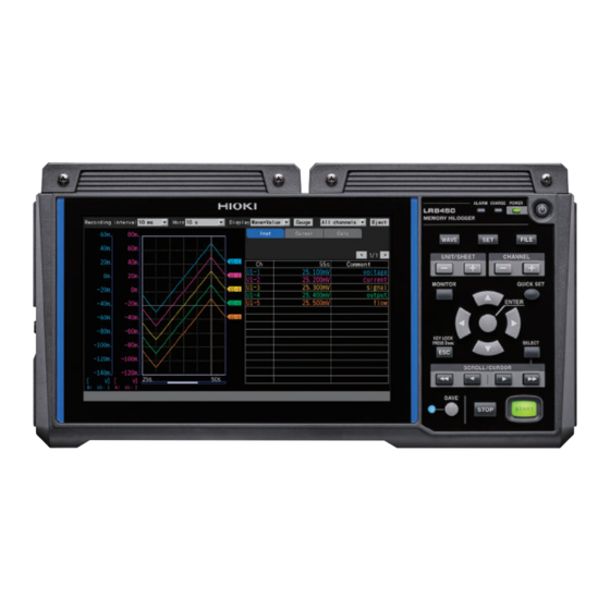
Hioki MEMORY HiLOGGER LR8450 Instruction Manual
Hide thumbs
Also See for MEMORY HiLOGGER LR8450:
- Instruction manual (400 pages) ,
- Quick start manual (120 pages) ,
- Quick start manual (16 pages)
Table of Contents
Advertisement
Quick Links
Advertisement
Table of Contents

Subscribe to Our Youtube Channel
Related Manuals for Hioki MEMORY HiLOGGER LR8450


Summary of Contents for Hioki MEMORY HiLOGGER LR8450
- Page 1 LR8450 LR8450-01 Instruction Manual MEMORY HiLOGGER Read carefully before use. Keep for future reference. Feb. 2022 Revised edition 3 LR8450A964-03 22-02H GlobalTestSupply www. .com Find Quality Products Online at: sales@GlobalTestSupply.com...
-
Page 2: Table Of Contents
Contents Introduction ........81 ............1 Waveform display Gage (scale) display .........85 About the Notations Used in This Manual ..3 Numerical value display ......86 How to Use This Manual .........5 ....89 Moving waveforms (scrolling) Scroll bar (waveform display position) ..91 Settings and Operation Enlarging and shrinking the waveform ..........91 horizontally... - Page 3 Saving and Loading Numerical and Data Waveform Calculations Data That Can Be Saved and Performing Numerical Loaded Calculations ..........136 .........192 Formatting Media ..194 ........139 Configuring numerical calculations Real-time numerical calculations Saving Data .........141 ......197 (automatic calculations) .....142 Auto save (real-time save) Numerical calculations after Manual saving (selective saving, measurement (manual calculations)
- Page 4 Connecting the instrument to the LR8531 Wireless Universal Unit ....345 .....238 computer with a USB cable ..353 LR8532 Wireless Voltage/Temp Unit Configuring and Establishing LR8533 Wireless High Speed Voltage ............360 a LAN Connection Unit ......239 ....363 LR8534 Wireless Strain Unit Configuring the computer’s network LR8535 Wireless CAN Unit .....367...
- Page 5 Contents ............412 Alarms ..412 Saving data onto the storage media Numerical calculation ......412 ......412 Waveform calculations .....413 Resetting waveform calculations Logger Utility ..........413 11.15 Data Handling ........414 11.16 Displaying the Certification Number ..........415 11.17 Mouse Operation on the Waveform Screen ..........416 Index GlobalTestSupply...
-
Page 6: Introduction
Introduction Introduction Thank you for purchasing the Hioki LR8450/LR8450-01 Memory HiLogger. To ensure your ability to get the most out of the instrument over the long term, please read this manual carefully and keep it available for future reference. Latest instruction manual The contents of this manual are subject to change, for example as a result of product improvements or changes to specifications. - Page 7 Introduction Trademarks • Microsoft, Windows, Excel, Internet Explorer, and Visual Basic are the registered trademarks or trademarks of Microsoft Corporation in the U.S., Japan, and other countries. • Google Chrome is a trademark of Google, Inc. Screen font • The typefaces included herein are solely developed by DynaComware Taiwan Inc. GlobalTestSupply www.
-
Page 8: About The Notations Used In This Manual
About the Notations Used in This Manual About the Notations Used in This Manual Safety notations This manual classifies seriousness of risks and hazard levels as described below. Indicates an imminently hazardous situation that, if not avoided, will result in DANGER death of or serious injury to the operator. - Page 9 About the Notations Used in This Manual Notations related to standards compliance Indicates compliance with the Waste Electrical and Electronic Equipment (WEEE) Directive in EU member nations. Indicates that the instrument is targeted for recycling under the Act on the Promotion of Effective Utilization of Resources.
-
Page 10: How To Use This Manual
How to Use This Manual How to Use This Manual How to open screens : Main tab : Sub tab Step number Numbers are the same as those used in the instructions. Selections and explanations Indicates the selections that can be made by pressing the ENTER key and explains them. - Page 11 How to Use This Manual GlobalTestSupply www. .com Find Quality Products Online at: sales@GlobalTestSupply.com...
-
Page 12: Settings And Operation
Settings and Operation This chapter introduces basic settings and instrument operation. Before starting measurement, you must set measurement conditions such as recording interval and range. You must also configure input channel settings such as input signal types and ranges. 1.1 Performing Basic Operations ..........p. 8 1.2 Registering Wireless Modules ..........p. ... -
Page 13: Performing Basic Operations
1.1 Performing Basic Operations Instructions > > : main tab; : sub tab) In this manual, the active item is said to have “focus.” The background of the selected item will turn yellow. Press the key to display the settings screen. Select the main tab you wish to configure with the Left Arrow Right Arrow... -
Page 14: Value Entry Method
Performing Basic Operations Value entry method This section describes how to enter values. Numerical value entry window Clear Clears the value. Deletes one digit (backspace). ← Moves left one digit. → Moves right one digit. Accepts the value. Cancel Closes the window without entering a value. Select the desired value with the Left Arrow,... -
Page 15: Text Entry Method
Performing Basic Operations Text entry method This section describes how to enter comments and filenames. You can enter single-byte alphanumeric and characters only. Text entry window Select a character with the Left Arrow, Right Arrow, Arrow, and Down Arrow keys and press the ENTER key. - Page 16 Performing Basic Operations Text entry You can perform the operations listed below by choosing the operation on the screen and pressing ENTER key. You can also use the corresponding key to perform the same operation. Operation on screen Corresponding key Description START Accepts the character.
- Page 17 Performing Basic Operations Description example Description #HIOKI_FIXED_FORM Write at the first line of the file. The instrument can recognize the file as a word list file. #TitleComment Write a word list for title comments. Word 1 Up to 40 characters Word 20 Write a word list for channel comments.
-
Page 18: Entering Text With The Keyboard
Performing Basic Operations Entering text with the keyboard You can connect a keyboard to the instrument's USB connector and use it to interact with the screen interface and enter alphanumeric text. Comments Press the space bar while the comment field has focus. The cursor will flash, and the software will switch to input mode. -
Page 19: Registering Wireless Modules
Registering Wireless Modules 1.2 Registering Wireless Modules The LR8450-01 is capable of communications with not only plug-in modules but also wireless modules. Before use, you need to register wireless modules in the LR8450-01. You can register up to seven wireless modules in the LR8450-01. Please make sure that the Z3230 Wireless LAN Adapter has been attached to the wireless module. - Page 20 List method The list will show the connectible wireless modules so that you can choose the modules you wish to register. Press the ENTER key while [Execute] on the search window is selected. The instrument will start to search for the connectible wireless modules.
- Page 21 Registering Wireless Modules Auto connect method Allows you to use the keys on wireless modules. Perform this method for connecting the instrument and the wireless module on a one-to-one basis. Attempting to perform this method for a multiple-piece connection will cause an error, disabling the auto-connect registration for several minutes.
-
Page 22: Deregistering The Wireless Modules
Registering Wireless Modules Deregistering the Wireless Modules You can deregister the wireless modules. You can register up to seven wireless modules in the LR8450-01. If required, deregister the unwanted wireless modules. > Press the ENTER key while [Delete] is selected. The window prompting you to select the modules you wish to deregister will be displayed. -
Page 23: Setting Measurement Conditions
Setting Measurement Conditions 1.3 Setting Measurement Conditions This section describes how to configure settings such as the recording interval and recording time. Settings cannot be changed while measurement is in progress. Stop measurement and then change the settings. You can select the recording method. Sets the recording time setting to [Continuous]. - Page 24 Setting Measurement Conditions > > Enter a title comment in the [Title comment] field (optional). See “Title comments” (p. 6 4). Configure the [Start] [Stop] settings. You can start measurement at the specified time and date. Once measurement has started, recording will start based on the trigger settings.
- Page 25 Setting Measurement Conditions Under [Recording mode], select type of recording. Normal Data is recorded in synchronization with the internal clock. The setting cannot be changed from [Normal]. Under [Recording interval], select the data capture interval. Example: Choosing [10 ms] will cause data to be captured at a 10 ms interval (100 times per second).
- Page 26 Setting Measurement Conditions When the recording time is set to [Specified time] and repeat recording is set to [ON] Internal processing will take some time (downtime) between the time that recording stops after the specified amount of time has elapsed and the start of the next recording operation. Recording is not performed during this time.
-
Page 27: Measurement Module Data Refresh Intervals
Setting Measurement Conditions Measurement module data refresh intervals This section describes how to set the data refresh interval for each measurement module separately from the instrument’s recording interval. Data refresh interval Interval at which measurement modules refresh measurement data Interval at which the instrument captures data from measurement Recording interval modules >... - Page 28 Setting Measurement Conditions *5: For the U8555/LR8535, the maximum number of channels that can be set varies as indicated in the following table based on the data refresh interval. U8555, LR8535 data fresh intervals 10 ms 20 ms 50 ms 100 ms or longer Maximum number of channels that can be set...
- Page 29 Setting Measurement Conditions Example setting What you want to do Data refresh interval Recording interval Record a signal that’s changing quickly Shorter Shorter (electrical signal, etc.) Record a signal that’s changing slowly Longer Longer (temperature, etc.) Record fast and slow signals at the same time Shorter for modules used to Shorter measure fast signals...
-
Page 30: Configuring Input Channels
Configuring Input Channels 1.4 Configuring Input Channels Configure input channels for voltage measurement, temperature measurement, etc. Un-m (plug-in module), Rn-m (wireless module) Channel The letters n and m represent a module number and a channel number, respectively. Selects the type of measurement target. Input Voltage, thermocouple, humidity, etc. - Page 31 Configuring Input Channels Individual settings screen A settings screen will be displayed for each channel. Under [Channel], select the module and channel to configure*. Configure the range and display for the selected channel. A waveform monitor is shown on the left side of the screen. You can also switch the display format to show numerical values.
- Page 32 Configuring Input Channels Settings list screen This screen displays a list of settings for each module. For more information about the settings list screen, see “1.9 Configuring Channels in a List” (p. 6 7). The following settings can be configured on the settings list screen: •...
-
Page 33: Measuring Voltage
Configuring Input Channels Measuring voltage This section describes how to configure settings on the individual settings screen when measuring voltage. You can use [Input] on the settings list screen to configure the settings. (See p. 6 7.) Applicable modules: U8550, U8551, U8552, U8553, U8554, LR8530, LR8531, LR8532, LR8533, LR8534 >... - Page 34 Configuring Input Channels (For the U8554 or LR8534 Strain Unit) Under [Filter], select the cutoff frequency. Auto 4 Hz [Auto] See the table in “Measuring strain” (p. 3 6) for a list of cutoff frequencies when is selected. When measuring instrumentation devices Ω...
-
Page 35: Measuring Temperature (With Thermocouples)
Configuring Input Channels Measuring temperature (with thermocouples) This section describes how to configure settings on the individual settings screen when measuring temperature using thermocouples. You can use [Input] on the settings list screen to configure the settings. (See p. 6 7.) Applicable modules: U8550, U8551, U8552, LR8530, LR8531, LR8532 >... - Page 36 Configuring Input Channels Under [Burn out], select whether you wish to detect wire breaks. Does not detect thermocouple wire breaks. Values will vary when a thermocouple experiences a wire break. Detects thermocouple wire breaks when measuring temperature using thermocouples. [BURNOUT] The numerical value display and cursor value will be indicated as when a...
- Page 37 Configuring Input Channels Thermocouple wire break detection • The system checks for wire breaks by applying a minuscule current at the date refresh intervals when measuring temperature using thermocouples. • Measured values are not affected since wire breaks are detected when measurement is not being performed.
-
Page 38: Measuring Temperature (With Resistance Temperature Detectors)
Configuring Input Channels Measuring temperature (with resistance temperature detectors) This section describes how to configure settings on the individual settings screen when measuring temperature using resistance temperature detectors. You can use [Input] on the settings list screen to configure the settings. (See p. 6 7.) Applicable modules: U8551, LR8531 >... -
Page 39: Measuring Humidity
Configuring Input Channels Measuring humidity This section describes how to configure settings on the individual settings screen when measuring humidity with the optional Humidity Sensor. You can use [Input] on the settings list screen to configure the settings. (See p. 6 7.) Applicable modules: U8550, U8551, U8552, LR8531 Applicable sensor: Z2000 Humidity Sensor >... -
Page 40: Measuring Resistance
Configuring Input Channels Measuring resistance This section describes how to configure settings on the individual settings screen when measuring resistance. You can use [Input] on the settings list screen to configure the settings. (See p. 6 7.) Applicable modules: U8551, LR8531 >... -
Page 41: Measuring Strain
Configuring Input Channels Measuring strain This section describes how to configure settings on the individual settings screen when measuring strain or vibration with a strain gage or strain gage-type converter. [Input] You can use on the settings list screen to configure the settings. (See p. 6 7.) Applicable modules: U8554, LR8534 Measuring strain See “11.2 Measuring Strain”... - Page 42 Configuring Input Channels Under [Filter], select the cutoff frequency. Auto 4 Hz When [Auto] is selected, the low-pass filter’s cutoff frequency will automatically be set as described in the following table based on the set data refresh interval: Data refresh interval Cutoff frequency Data refresh interval Cutoff frequency...
-
Page 43: Measuring Can Signals
Configuring Input Channels Measuring CAN signals For more information, see the “CAN Editor Instruction Manual” on the included CD. Applicable modules: U8555, LR8535 Integrating pulses You can perform measurement by integrating the pulse count from an integrating wattmeter, flow meter, or similar device. This section describes how to configure settings on the individual settings screen when performing integration measurement. - Page 44 Configuring Input Channels Under [Slope], select the slope to count. ↑ Integrates the number of times the pulse switches from low level to high level (rising). ↓ Integrates the number of times the pulse switches from high level to low level (falling). Under [Threshold], select the level used for counting.
-
Page 45: Measuring Rotational Speed
Configuring Input Channels Measuring rotational speed This section describes how to measure the pulses output by a rotary encoder, tachometer, or similar device. The instrument counts the number of pulses per second and calculates the rotational speed. This section describes how to configure settings on the individual settings screen when measuring rotational speed. - Page 46 Configuring Input Channels Under [Slope], select the slope to count. ↑ Integrates the number of times the pulse switches from low level to high level (rising). ↓ Integrates the number of times the pulse switches from high level to low level (falling). Under [Threshold], select the level to count.
- Page 47 Configuring Input Channels When the range is [r/min] If the time t [s] is less than t (time specified with the smoothing), the displayed rotational speed will be the actual rotational speed. (However, t is equal to or more than 2 s.) If an unintentional trigger activates, set the smoothing time at 1 s.
-
Page 48: Measuring Logic Signals
Configuring Input Channels Measuring logic signals This section describes how to configure settings on the individual settings screen when measuring logic signals. You can use the settings list screen to configure the settings. (See p. 6 9.) External control terminals: Pulse input terminals P1 to P8 >... -
Page 49: Treatment Of Data That Exceeds The Measurable Range
Configuring Input Channels Treatment of data that exceeds the measurable range Regardless of the measurement target, measured values that exceed the measurable range are treated as over-range values, resulting in a display of either [+OVER] [-OVER] on the numerical value display and for A/B cursor values. Treatment of such values in saved data and calculation results is described in “11.15 Data Handling”... -
Page 50: Configuring Can Settings
Configuring CAN Settings 1.5 Configuring CAN Settings This section describes how to check settings sent from the CAN Editor and configure CAN Unit settings, user frame transmission, and measured value output mode output settings from the LR8450. Configuring CAN Unit settings >... - Page 51 Configuring CAN Settings (If operating in [Measured value output mode]) Select whether to output measured values under [Measured value output]. Settings controlling measured value output are configured with the CAN Editor. On the LR8450, you can select whether to output measured values overall. Disables CAN Unit measured value output.
- Page 52 Configuring CAN Settings Configuring port settings Select the CAN Unit’s port. Select the interface. CAN mode CAN FD CAN FD mode (ISO 11898-1:2015 compliant) CAN FD(non-ISO) CAN FD (non-ISO) mode (not ISO compliant) Select the [Terminator] check box. Places CAN_H and CAN_L in an open state. ...
-
Page 53: Configuring User Frame Transmission
Configuring CAN Settings Configuring user frame transmission When operating in receive mode, you can send user-defined CAN frames to the CAN bus. This section describes how to select the frames to send to the CAN bus and the timing at which they will be sent. - Page 54 Configuring CAN Settings Detailed settings for user frame transmission 1 2 2 The user frame number is displayed. Select whether to send the frame. Select the CAN port from which to send the frame. Port1 Port2 Under [Timing], select when to send the frame. Start ...
- Page 55 Configuring CAN Settings Under [Type], select the type of frame. CAN Standard Standard ID (0h to 7FFh) CAN frame CAN Extended Extended ID (0h to 1FFFFFFFh) CAN frame CAN Standard Standard ID (0h to 7FFh) CAN FD frame CAN FD Extended Extended ID (0h to 1FFFFFFFh) CAN FD frame Under [ID], set the send ID to use when sending the configured content as a hexadecimal value.
- Page 56 Configuring CAN Settings CAN frame transmission when using manual send timing 2 2 3 3 When measurement starts, [CAN frame transmission] will be displayed on the [Wave+Set] waveform screen. Press the ENTER key while [CAN frame transmission] is selected. A dialog box will be displayed. Send the frames whose user frame number checkboxes are selected with [Send].
-
Page 57: Configuring The Waveform Display
1.6 Configuring the Waveform Display This section describes how to set how waveforms are displayed (display color, display position, zoom factor, etc.). Configuring the display of the vertical axis This section describes how to configure the display in the vertical axis direction. You can set the waveform display position and zoom factor for each channel on the individual settings screen. - Page 58 Configuring the Waveform Display Under [Zero position], set where to place the waveform’s zero point (0 V, 0°C, etc.). −50% 150% (When the zoom factor is set to [×1]) You can set off-screen values. 150% With a vertical axis zoom factor of 1×: Up to 150% 100% Top edge of screen: 100% Screen...
- Page 59 Configuring the Waveform Display Example: Waveform from −5 V to +5 V −5 V With voltage axis zoom factor of 1× With voltage axis zoom factor of 2× Zero position setting range: −50% to 150% Zero position setting range: −150% to 250% With zero position of 0% With zero position of 0% 10 V...
- Page 60 Configuring the Waveform Display Setting upper and lower limit values You can set the waveform’s display range by specifying upper and lower limit values for the screen. Since you can specify any desired range, you can enlarge the waveform to show only the necessary portion.
-
Page 61: Other Display Settings
Configuring the Waveform Display Other display settings This section describes how to change the display’s zoom factor in the horizontal axis direction. This feature allows you to view fine-grained changes by enlarging the waveform or check the overall state by shrinking the waveform. You can configure the horizontal axis display and set the method used to display vertical axis values. - Page 62 If measurement was started from the Logger Utility When the recording interval is a value from 10 ms to 500 ms, the instrument’s [Horizontal axis] setting is limited to a maximum value of 10 s while measurement is in progress. (The limit does not apply once measurement has stopped.) The refresh interval for the instrument’s waveform rendering is limited to about once every 5 seconds.
-
Page 63: Using The Scaling Function
1.7 Using the Scaling Function This section describes how to use the scaling function to convert voltage values measured by the instrument into the measurement target’s physical properties (current, temperature, etc.) and then display or record them. Converted values can be displayed using decimal or scientific notation. Example: Before scaling After scaling... - Page 64 Using the Scaling Function (When the scaling conversion method is set to [Ratio]) Enter the slope and the offset in [Slope] and [Offset], respectively. Select the numerical value entry item and press the ENTER key to display the numerical value setting window.
- Page 65 Using the Scaling Function (When the scaling conversion method is set to [Rating]) (Available only when U8554 or LR8534 Strain Unit is used) Enter the rated capacity and rated output in [Capacity] and [Output], respectively. Set the rated capacity and rated output* (μV/V) according to values in the inspection results sheet for the strain gage-type converter.
- Page 66 Using the Scaling Function Scaling settings during integration measurement You can use the scaling function to convert the integrated pulse count to the measurement target’s physical properties (watt hours, volt-amperes, etc.) and then display or record the result. The pulse output device will have predetermined physical quantity that corresponds to 1 pulse or a number of pulses that corresponds to a value of one in the basic units (for example, 1 kWh, 1 L, >...
- Page 67 Using the Scaling Function Enter physical quantity per pulse or the number of pulses (example: 1 c = 1 pulse) that corresponds to a value of one in the basic units. Select the numerical value entry item and press the ENTER key to display the numerical value setting window.
-
Page 68: Configuring The Scaling Of The U8554/Lr8534 Strain Unit
Using the Scaling Function Configuring the scaling of the U8554/LR8534 Strain Unit Strain gage-type converter You can use values on the Strain gage-type converter’s inspection record to convert the converter’s output into physical quantities. Two methods are available: using a calibration factor* and using rated capacity and rated output. -
Page 69: Entering Comments
Entering Comments 1.8 Entering Comments This section describes how to enter measurement titles, channel comments, and module identifiers. Title comments This section describes how to enter a string of text to serve as the measurement title. (Up to 40 single-byte characters) See “Text entry method”... -
Page 70: Channel Comments
Entering Comments Channel comments This section describes how to enter a string of text for each channel. (Up to 40 single-byte characters) See “Text entry method” (p. 1 0). Channel comments are displayed on the screen when the waveform screen is set to [Wave+Value]. Channel comments allow you to identify channels when measuring numerous channels. -
Page 71: Module Identifiers
Entering Comments Module identifiers This section describes how to enter an identifier (string of text) for each module. (Up to 16 characters) See “Text entry method” (p. 1 0). You can use module identifiers to identify modules when using multiple modules. >... -
Page 72: Configuring Channels In A List
1.9 Configuring Channels in a List This section describes how to review module settings on the list. > > [Unit [Remote n] (n = 1, 2, . . .) Settings list screen: [Input] On the sub tab, select the module whose settings you wish to display in the list. Select the item to display. - Page 73 Configuring Channels in a List (U8552, LR8532) • Press the ENTER key while [16-30>] is selected to display CH16 to CH30. • Press the ENTER key while [1-15>] is selected to display CH1 to CH15. Select a channel number and press the ENTER key.
- Page 74 Configuring Channels in a List Pulse settings list screen > > Settings list screen: [Input] Input type: Integration Input type: Logic Input type: Rotational speed Input type Input type Range When the input type is [RevSpd]: Count reference time Integration mode When the input type is [Count]: Integration method Pulse count When the input type is [RevSpd]: Number of pulses per revolution...
- Page 75 Configuring Channels in a List Settings list screen: [Display] Display settings Displays setting method Zoom factor When the display setting is [Position]: Waveform display zoom factor Upper limit value [Up/Low Lim]: Screen upper limit value When the display setting is Zero position When the display setting is [Position]: Waveform zero position (0 V, 0°C, etc.) Lower limit value...
- Page 76 Configuring Channels in a List Settings list screen: [Comment] Comment Comments for individual channels Settings list screen: [Numerical calc] Threshold value Threshold value for numerical calculations (Availability, ON time, OFF time, ON count, OFF count) Threshold values will be used for numerical calculations. For more information about threshold values, see “Configuring numerical calculations”...
-
Page 77: Copying Channel Settings
Configuring Channels in a List Copying channel settings This section describes how to copy one module’s settings to another module. > > [Unit [Remote n] (n = 1, 2, . . .) Press the ENTER key while [Copy...] is selected. The settings window will open. -
Page 78: Configuring Channel Settings At Once
Configuring Channels in a List Configuring channel settings at once This section describes how to turn the measurement on or off and configure the waveform display color settings for all channels on a module. > > [Unit [Remote n] (n = 1, 2, . . .) Select the measurement ON/OFF check box and press the ENTER key. -
Page 79: Aligning Waveforms' Zero Positions
Configuring Channels in a List Aligning waveforms’ zero positions This section describes how to align zero positions for displayed waveforms at a specified interval based on channel 1 of the sub tab unit. > > [Unit n] (n = 1, 2, . . .) Press the ENTER key while... - Page 80 Example settings Setting CH1’s zero position to 85% and aligning at a 5% interval Channel Waveform zero position CH1 (initial channel) 85% (reference channel) 80% (subsequently reducing by 5% per waveform) (omitted) (omitted) CH14 CH15 Waveform screen before alignment Waveform screen after alignment GlobalTestSupply www.
-
Page 81: Performing Zero Adjustment
1.10 Performing Zero Adjustment This section describes how to correct misalignment of inputs and set the instrument’s reference voltage to 0 V. Perform zero adjustment if the reference voltage is not 0 V with a pair of input terminals short- circuited. -
Page 82: Checking Input Signals (Monitor Function)
Checking Input Signals (Monitor Function) 1.11 Checking Input Signals (Monitor Function) This section describes how to check input waveforms to verify that settings such as the range and display range have properly been configured before starting measurement. Press the MONITOR key to display waveforms and values on the monitor screen. -
Page 83: Starting And Stopping Measurement
1.12 Starting and Stopping Measurement Press the START key to start measurement. Press the STOP key to stop measurement. When the [Operation error prevention] setting is [ON], an operation confirmation window will be displayed. Press the ENTER key while [Yes] is selected to start measurement. -
Page 84: Observing Waveforms
1.13 Observing Waveforms WAVE Press the key to display the waveform screen. The waveform screen is displayed at all times while measurement is in progress. The screen provides the following functionality: • Moving (scrolling) waveforms • Moving waveforms while measurement is in progress (to check past waveform data) •... - Page 85 Observing Waveforms Reference Name Description page Channel selection Allows you to select the channel to configure. – Measurement Allows you to turn measurement on or off. p. 2 8 Waveform color Allows you to select the waveform display color. p. 2 8 Input type Allows you to select the type of input.
-
Page 86: Waveform Display
Observing Waveforms Waveform display This section describes how to change the method used to display measured waveforms. Under [Display], select the waveform display method. Wave+Set, Wave, Wave+Value, Value, Alarm, XY+Set*, XY+Value* WAVE You can also select the display method with the key. - Page 87 Observing Waveforms [Wave+Value] [Value] GlobalTestSupply www. .com Find Quality Products Online at: sales@GlobalTestSupply.com...
- Page 88 Observing Waveforms [Alarm] [XY+Set] GlobalTestSupply www. .com Find Quality Products Online at: sales@GlobalTestSupply.com...
- Page 89 Observing Waveforms [XY+Value] GlobalTestSupply www. .com Find Quality Products Online at: sales@GlobalTestSupply.com...
-
Page 90: Gage (Scale) Display
Observing Waveforms Gage (scale) display This section describes how to display a gage (scale) for any channel on the left side of the screen. The gage can be used to check the waveform and its values. Two gages (A and B) can be displayed. You can choose the channels for which to display a gage. -
Page 91: Numerical Value Display
Observing Waveforms Numerical value display This section describes how to select the numerical value display method. [Value] screen This screen displays only numerical values. Select the value to display. Instantaneous values, maximum values, minimum values, average values, and peak- to-peak values Instant Most recent measured value (INST) Maximum*... - Page 92 Observing Waveforms [Wave+Value] screen You can choose any of three types of information to display on the right side of the screen. (1) Instantaneous: Measured values most recently obtained or shown on the right portion of the waveform screen (2) Cursor: A/B cursor values GlobalTestSupply www.
- Page 93 Observing Waveforms (3) Numerical calculation: Numerical calculation results GlobalTestSupply www. .com Find Quality Products Online at: sales@GlobalTestSupply.com...
-
Page 94: Moving Waveforms (Scrolling)
Observing Waveforms Moving waveforms (scrolling) This section describes how to move (scroll) the measured waveform horizontally (along the time axis). Since waveforms can also be moved while measurement is in progress, you can check past waveforms during measurement. Past Most Screen recent Scrolls quickly toward the most... - Page 95 Observing Waveforms Under [Display], set the display to [Wave+Set], [Wave], or [Wave+Value]. Press the SELECT key to display the Scroll icon. Each time you press the SELECT key, the display will switch between the Cursor icon (A/B cursor movement) and the Scroll icon (waveform movement). For more information about the Scroll icon, see “1.13 Observing Waveforms”...
-
Page 96: Scroll Bar (Waveform Display Position)
Observing Waveforms Scroll bar (waveform display position) A scroll bar is displayed on the bottom of the screen. You can use the scroll bar to check which part of the entire waveform is being displayed. The width shown on the scroll bar varies with the recording time and horizontal axis display settings. -
Page 97: Waveform Search
Waveform search This section describes how to search a measured waveform for a specific point of interest. This function cannot be used while measurement is in progress. Under [Settings], select [Search]. A number of search-related settings will be displayed. Under [Type], select the search method. Level Searches for points that cross the specified level. - Page 98 Observing Waveforms (When [Type] is set to [Level], [Window], [Maximal], or [Minimal]) Press the ENTER key while either [<] [>] under [Execute] is selected. The search will be performed. If the search returns multiple points, you can move to the next point [>] or to the previous point with [<].
-
Page 99: Jump Function (Changing The Display Position)
Observing Waveforms Jump function (changing the display position) This section describes how to use the scroll bar to change the waveform’s display position (jump function). Under [Settings], select [Jump]. The jump-related settings will be displayed. Press the ENTER key while [Manual] is selected. -
Page 100: Using The A/B Cursors
1.14 Using the A/B Cursors This section describes how to read values from the measured waveform using the A/B cursors. You can also use the cursors to specify a range for saving data or performing numerical calculations. Reading values from the waveforms This section describes how to read measured values, times, and time differences between cursors using the A/B cursors. - Page 101 Select the information to display. A, B A cursor measured value, B cursor measured value A, B−A A cursor measured value, difference in measured values at the B and A cursors (B-A) B, B−A B cursor measured value, difference in measured values at the B and A cursors (B-A) A, Comment A cursor measured value, channel comments B, Comment...
-
Page 102: Specifying A Waveform Range
Using the A/B Cursors Specifying a waveform range This section describes how to specify a waveform range using the A/B cursors. When saving waveform data, you can save only the data in the specified range. You can also specify the range over which to perform numerical calculations. Range specification is performed using the vertical axis cursors. -
Page 103: X-Y Compositing
X-Y Compositing 1.15 X-Y Compositing This section describes how to create X-Y composites using any two channels. (You can composite up to eight waveforms.) You can specify the range for X-Y compositing with the A and B cursors. You can generate X-Y composites either during or after measurement. Data only saved in the internal buffer memory can be redrawn (recomposited). -
Page 104: Performing X-Y Compositing During Measurement
X-Y Compositing Performing X-Y compositing during measurement Enable the X-Y compositing function on the settings screen and configure the settings as necessary (p. 9 8). Under [Display], set the display to [XY+Set] or [XY+Value]. Start measurement. GlobalTestSupply www. .com Find Quality Products Online at: sales@GlobalTestSupply.com... -
Page 105: Performing X-Y Compositing After Measurement
X-Y Compositing Performing X-Y compositing after measurement Prepare the measurement data. Enable the X-Y compositing function on the settings screen and configure the settings as necessary (p. 9 8). Under [Display], set the display to [XY+Set] or [XY+Value]. Press the ENTER key while [Re-render]... -
Page 106: Configuring X-Y Compositing
X-Y Compositing Configuring X-Y compositing Comments for each channel will be displayed. 4, 5, 6 4, 5, 6 Enable the X-Y compositing function on the settings screen (p. 9 8). Under [Display], set the display to [XY+Set]. Under [Composite range], select the X-Y compositing range. [A-B] setting lets you specify the range using the A and B cursors. -
Page 107: Checking X-Y Composite Waveform Values
X-Y Compositing Checking X-Y composite waveform values This section describes how to read measured values for X-Y composite waveforms by either displaying instantaneous values at the same time as the waveforms or using the C and D cursors. Checking instantaneous values Under [Display], set the display to [XY+Value]. - Page 108 X-Y Compositing Using the trace cursors to check values Under [Display], set the display to [XY+Value]. Set the display item to [Cursor]. Select [Trace] under the cursor settings. Select the target cursor(s). Cursor C Cursor Sync SCROLL/CURSOR You can manipulate the target cursor(s) using the keys.
- Page 109 X-Y Compositing Using the horizontal and vertical cursors to check values Under [Display], set the display to [XY+Value]. Set the display item to [Cursor]. Select [Cross] under the cursor settings. Select the target direction. Vertical Horizontal Select the target cursor(s). Cursor C Cursor Sync...
-
Page 110: Configuration Navigator (Quick Set)
Configuration Navigator (Quick Set) 1.16 Configuration Navigator (Quick Set) Press the QUICK SET key to display the following guides. • Wireless module registration guide • Strain gage connection guide • External control terminal connection guide • Countermeasures against errors in communications with wireless modules •... -
Page 111: Strain Gage Connection Guide
Configuration Navigator (Quick Set) Strain gage connection guide This section describes how to display the connection diagram for strain gages and the DIP switch configurations. Select [Strain gauge connection guide]. Press the ENTER key. A strain gage connection guide will be displayed. Select the connection method with the Right Arrow Left Arrow... -
Page 112: External Connection Guide
Configuration Navigator (Quick Set) External connection guide This section describes how to display the terminal numbers and signal names of the external control terminal, which is on the left side of the instrument. Select [External connection guide]. Press the ENTER key. -
Page 113: Action During Communication Error
Configuration Navigator (Quick Set) Action during communication error This section describes countermeasures against errors in communications between the instrument and the wireless modules. Select [Action during communication error]. Press the ENTER key. [Action during communication error] guide will be displayed. Use the Up Arrow Down Arrow... -
Page 114: Loading Setting Conditions
Configuration Navigator (Quick Set) Loading setting conditions This section describes how to load setting conditions that have been saved in the instrument's internal backup memory. Select [Load settings data]. Press the ENTER key. A list of setting conditions will be displayed. Press the ENTER key with one of the... -
Page 115: Measurement Data
Measurement Data 1.17 Measurement Data The cautions about measurement data are described as follows. Synchronization and time lag The instrument and each wireless module have a clock used for sampling data. Plug-in units use the instrument’s clock as the basis for sampling. During measurement, differences in sampling timing will develop gradually between wireless units and plug-in units, and between individual wireless units, because the instrument and wireless units keep time with different degrees of precision. -
Page 116: If Communicates With A Wireless Module Are Disrupted
Measurement Data If communicates with a wireless module are disrupted Each wireless module is internally equipped with the buffer memory. If a wireless module cannot communicate with the instrument, which causes a data transmission error, the module will temporarily save the data in its buffer memory. When communications are restored, the module will resend the data for recovery. - Page 117 Measurement Data GlobalTestSupply www. .com Find Quality Products Online at: sales@GlobalTestSupply.com...
-
Page 118: Trigger Function
Trigger Function Triggers provide functionality for starting and stopping measurement based on specific conditions and signals. When a specific condition (a trigger condition) occurs, the trigger is said to activate. The points at which triggers activate (i.e., the points in time at which trigger conditions are satisfied) are known as trigger points, which are identified by the mark. - Page 119 The instrument allows the following specific conditions to be set: Specific Description Reference condition page Start trigger Starts recording when the trigger condition is satisfied. p. 1 16 Example: Start recording when the temperature reaches or exceeds 50°C. Stop trigger Stops recording when the trigger condition is satisfied.
-
Page 120: Trigger Meanings
2.1 Trigger Meanings This section describes how to set start or stop conditions for measurement. You do so by setting the type of trigger (level, window, or pattern) and the slope (signal rising or falling). Trigger types The following three types of triggers are provided: Type Operation Description... -
Page 121: Enabling The Trigger Function
2.2 Enabling the Trigger Function This section introduces how to start and stop recording using the trigger function. Shared settings > > Under [Trigger], set the trigger function to [ON]. The trigger function will be set to [ON], and trigger settings will be enabled. Under [Timing], select the operation to perform when the trigger activates. - Page 122 Enabling the Trigger Function Under [Condition], select the condition for activating the trigger. Set the activation condition between triggers (analog, pulse, logic, waveform calculation, external, and interval) as a logical AND or logical OR operation. Recording will start immediately (free-run) if all trigger sources are OFF (if no trigger setting has been made).
- Page 123 Enabling the Trigger Function Relationship between pre-triggers and recording time If the recording time is shorter than the If the recording time is longer than the pre-trigger pre-trigger Data will be Measurement Measurement will measured before will stop at the stop when the and after the trigger.
-
Page 124: Analog Triggers, Pulse Triggers, Waveform Calculation Triggers
Analog Triggers, Pulse Triggers, Waveform Calculation Triggers 2.3 Analog Triggers, Pulse Triggers, Waveform Calculation Triggers This section describes how to set triggers for individual analog channels, pulse channels, or waveform calculation channels. The following triggers are available: • Level triggers •... - Page 125 Analog Triggers, Pulse Triggers, Waveform Calculation Triggers Pulse triggers Waveform calculation triggers See “Level triggers” (p. 1 21) and “Window triggers” (p. 1 23) . Configure the trigger function settings. You can also configure settings on the list screen without opening the settings window. When [Timing] is set to [Start], a...
-
Page 126: Level Triggers
Analog Triggers, Pulse Triggers, Waveform Calculation Triggers Level triggers Level triggers activate when the waveform crosses the specified level (the trigger level). You can set the direction in which the level is crossed (the slope). > > [Unit [Remote n] (n = 1, 2, . - Page 127 Analog Triggers, Pulse Triggers, Waveform Calculation Triggers Trigger level resolution The trigger level resolution (minimum setting width) varies with the range. Input Range Resolution Voltage 1 mV f.s. 0.001 mV 2 mV f.s. 0.002 mV 5 mV f.s. 0.005 mV 10 mV f.s.
-
Page 128: Window Triggers
Analog Triggers, Pulse Triggers, Waveform Calculation Triggers Window triggers This section describes how to specify a range (window) using upper and lower limit values and then activate a trigger when the waveform moves into or out of that range. You can activate a trigger either when the waveform enters the range (window IN) or when the waveform exits the range (window OUT). -
Page 129: Logic Triggers (Patterns)
Logic Triggers (Patterns) 2.4 Logic Triggers (Patterns) This section describes how to activate triggers with logic triggers. When the logic signal values (1 and 0) match the trigger pattern (1/0/X), the trigger will activate. This type of trigger can be selected when [Logic] has been selected for pulse (P1 to P8) input. - Page 130 Logic Triggers (Patterns) Select the P1 to P8 trigger pattern. Activates the trigger when the signal is (low). Activates the trigger when the signal is (high). Excludes from the trigger. The signal will be ignored. GlobalTestSupply www. .com Find Quality Products Online at: sales@GlobalTestSupply.com...
-
Page 131: Can Trigger
CAN Trigger 2.5 CAN Trigger This section describes how to select CAN channels for trigger conditions. Up to 100 channels can be specified. > > CAN trigger list screen 100 trigger conditions Un-m (n = 1, 2, . . .), (m = 1, 2, . . .) Rn-m Displays the CAN Unit numbers and channel numbers that are currently configured. - Page 132 CAN Trigger CAN trigger individual settings window (Level, Window) CAN trigger individual settings window (Logic) Under [Trigger No], select the trigger number from the 100 trigger conditions. Under [CAN Channel], set the CAN unit and channel to specify as the trigger condition. The channel type, ID, and comment for the specified CAN channel will be displayed.
- Page 133 CAN Trigger CAN trigger logic settings window GlobalTestSupply www. .com Find Quality Products Online at: sales@GlobalTestSupply.com...
-
Page 134: Applying Triggers Based On External Sources
Applying Triggers Based on External Sources 2.6 Applying Triggers Based on External Sources This section describes how to use signals inputted to the terminal I/O 3 to activate triggers. > > Under [External trigger], set the external trigger function to [ON]. ... -
Page 135: Activating A Trigger At A Set Interval
Activating a Trigger at a Set Interval 2.7 Activating a Trigger at a Set Interval Interval triggers This section describes how to activate a trigger at a set interval. When you set the interval trigger to [OR] or [AND], the repeat recording setting will be set to [ON] automatically. - Page 136 Activating a Trigger at a Set Interval OR and AND conditions Trigger : Trigger point; : Other trigger condition conditions Interval time Interval time Measurement start There is one enabled trigger during the interval. The trigger will not activate. Interval time Interval time Measurement start The trigger will not activate if it does not match other trigger conditions.
-
Page 137: Forcibly Activating The Trigger
Forcibly Activating the Trigger 2.8 Forcibly Activating the Trigger This section describes how to forcibly activate the trigger during the trigger standby state. You can forcibly activate trigger regardless of the trigger source settings. Press the ENTER key while [Forced trigger] is selected. -
Page 138: Example Trigger Settings
2.9 Example Trigger Settings This section introduces some example trigger settings. What you want to do (in table below) Capture data from the time the START key is pressed until the time the STOP key is No. 1 pressed. Capture data once for 1 min. starting from when the START key is pressed. - Page 139 Example Trigger Settings GlobalTestSupply www. .com Find Quality Products Online at: sales@GlobalTestSupply.com...
-
Page 140: Saving And Loading Data
Saving and Loading Data This chapter describes how to save settings conditions and waveform data on an SD Memory Card or a USB Drive. It also describes how to load previously saved data into the instrument to reproduce it. 3.1 Data That Can Be Saved and Loaded .........p. 1 36 3.2 Formatting Media ..............p. ... -
Page 141: Data That Can Be Saved And Loaded
Data That Can Be Saved and Loaded 3.1 Data That Can Be Saved and Loaded When you save data on an SD Memory Card or a USB Drive, the [HIOKI] folder containing the [LR8450] folder. will be created. Files are saved in folders as shown in the following diagram:... - Page 142 : Yes; –: No Saving Loading Filename Data type Format Folder name (Automatically On the On a Auto. Manual numbered from 1) instrument computer Setting Binary CONFIG CONF0001.SET – – conditions AUTO0001.MEM Binary * WAVE0001.MEM Waveform DATA\(date)* AUTO0001.CSV...
- Page 143 Data That Can Be Saved and Loaded IMPORTANT Hioki guarantees the operation of our optional SD Memory Card and USB Drive only. Operation of any other storage media cannot be guaranteed. Preparing for power outages and configuring associated settings NOTICE Do not use damaged media.
-
Page 144: Formatting Media
Formatting Media 3.2 Formatting Media Before using an SD Memory Card or a USB Drive for the first time, format the media. Press the FILE key. The file list screen on the SD Memory Card or USB Drive will be displayed. Press the FILE key to select the media to be formatted. - Page 145 Formatting Media Press the Down Arrow key to move to the media screen, and then press the SELECT key. The file operations window will be displayed. Pressing the ENTER key while [Media Format] is selected. The confirmation window will be displayed. Press the ENTER key.
-
Page 146: Saving Data
3.3 Saving Data Data can be saved using the following three methods: If you wish to automatically If you wish to save data If you wish to choose the save data during immediately when the type of data to save and measurement SAVE key is pressed... -
Page 147: Auto Save (Real-Time Save)
Auto save (real-time save) This section describes how to save waveform data (using the real-time save function) to media (an SD Memory Card or a USB Drive) while measurement is in progress. Numerical calculation results can also be saved to media automatically. You can also save both waveform data and numerical calculation results automatically. - Page 148 Media crash, which can occur because of system shutdown during saving operation, can be prevented. IMPORTANT Hioki guarantees the operation of our optional SD Memory Card and USB Drive only. Operation of any other storage media cannot be guaranteed. GlobalTestSupply www.
- Page 149 Saving Data > > Enter the filename to use during auto-save operation in the [File name] field (up to 8 single- byte characters). See “Text entry method” (p. 1 0). A serial number beginning from 0001 (in increments of one) will be appended to entered file names. Example: Filename: [ABC], Format: binary ABC0001.MEM, ABC0002.MEM, ABC0003.MEM, .
- Page 150 Under [Media], select the media to give priority when saving data. SD card USB flash drive When both an SD Memory Card and a USB Drive are inserted, the system will save data on the selected media. If the selected media is not inserted, the system will save data on the other media. Under [Format] in the...
- Page 151 [1 week] Example: If set to When measurement started on Sunday, December 29, 2019, the system will regard Monday, December 23, 2019 as the beginning of the week. The 19-12-23 folder will automatically be created. Example: If set to [1 month] When measurement started on December 29, 2019, the system will regard December 1, 2019 as the beginning of the month.
- Page 152 Saving Data Press the ENTER key while [Settings...] under [Text format] is selected. The settings window will open. Under [Decimal symbol], select the symbol to use as the decimal point. Period Uses a period (“.”) as the decimal point in numerical values. Comma Uses a comma (“,”) as the decimal point in numerical values.
- Page 153 Replacing (ejecting) media during real-time save operation This section describes how to replace media while real-time saving is enabled. It also describes how to check data on media during extended recording. Press the ENTER key while [Eject] on the top right of the waveform screen is selected. The media exchange window will be displayed.
-
Page 154: Manual Saving (Selective Saving, Immediate Saving)
Saving Data Manual saving (selective saving, immediate saving) This section describes how to save data using the SAVE key. You can select the operation to perform when the SAVE key is pressed. IMPORTANT • Data can be saved while the instrument does not perform measurement has. Data cannot be saved while measurement is in progress. - Page 155 Saving Data Under [Type], select the type of data to save. Waveform Saves waveform data. Screen shot Saves a screen image. (PNG format) Settings Saves the instrument’s setting conditions. Calc results Saves numerical calculation results. A2L file Used by the XCP master. See “9.10 Sending Measurement Data Using XCP on Ethernet”...
- Page 156 Saving Data (When [Downsampling] is set to [ON]) Under [Save data], select the data thinning method. Instant Saves the first data point. Example: With a setting of [1/5], only the first of each group of five data points will be saved.
-
Page 157: Selective Save Operation
Selective save operation This section describes how the system works when [Select & Save] is selected under [SAVE key settings]. Saving waveform data Press the SAVE key. A window will be displayed. Enter the filename in the [File name] field (up to 8 single-byte characters). See “Text entry method”... - Page 158 Saving Data Under [Format], select the file format. Binary Saves data in the instrument’s dedicated format (binary format). You will be able to load binary-form data on the instrument and with the Logger Utility. Text Saves data in text format. Although you will be able to load text-form data with spreadsheet software, you will not be able to load it on the instrument or with the Logger Utility.
- Page 159 Saving Data Saving setting conditions, screen images, and numerical calculation results Press the SAVE key. A window will be displayed. Enter the filename in the [File name] field (up to 8 single-byte characters). [File name] in “Saving waveform data” (p. 1 52). Under [Media], select the media on which to save data.
-
Page 160: Saving Settings To The Instrument's Internal Backup Memory
Saving Data Saving settings to the instrument’s internal backup memory This section describes how to save settings conditions to the instrument’s internal backup memory. This functionality is convenient when no storage media (SD Memory Card or USB Drive) is available. Up to five groups of settings (labeled No. - Page 161 Saving Data Under [Settings data list], select the desired operation with regard to the internal backup memory. Up to five groups of settings can be saved. Comment Changes the comment for groups No. 1 to No. 5. (Up to 20 double-byte or 40 single-byte characters) See “Text entry method”...
-
Page 162: Loading Data
Loading Data 3.4 Loading Data This section describes how to load data that has been saved on media (an SD Memory Card or a USB Drive). The LR8450/LR8450-01 can load the following two types of files saved with itself or other pieces of LR8450/LR8450-01 and CAN settings files (CES) saved by the PC application (CAN Editor). - Page 163 Loading Data Select the file loading mode on the confirmation window, and press the ENTER key while [OK] is selected. OVERWRITE Saves the loaded data by overwriting the mode existing setting conditions. The instrument’s present settings will change. The status bar will remain gray. VIEW mode Loads the data to browse.
-
Page 164: Auto-Setup Function
• Turn off the instrument. Initialize the instrument. Send the communications command. Auto-setup function This section describes how to automatically load the setting file on startup. [STARTUP.SET] [CONFIG] [HIOKI] > [LR8450]). The instrument Save the file in the folder (under will automatically load the file. -
Page 165: Managing Data
Managing Data 3.5 Managing Data This section describes how to manage data stored on an SD Memory Card or a USB Drive that has been inserted into the instrument. The following operations are available: • Formatting the SD Memory Card or USB Drive (p. 1 39) •... -
Page 166: Moving Between Levels (Folders)
Managing Data Moving between levels (folders) This section describes how to move within folders or to the next higher level. Press the Up Arrow Down Arrow keys to select the folder to which you wish to move. Press the Right Arrow key or ENTER key. -
Page 167: Deleting Data
Press the ENTER key. The file or folder will be deleted. To prevent data from being inadvertently deleted, files in the [HIOKI], [LR8450], and [DATA] folders cannot be deleted. Files whose read-only attribute is set cannot be deleted. Those files can be deleted on a computer. -
Page 168: Renaming Files And Folders
See “Text entry method” (p. 1 0). Enter the new name and press the START key. The filename will be changed. You cannot rename the following folders: [HIOKI], [LR8450], and [DATA]. GlobalTestSupply www. .com Find Quality Products Online at: sales@GlobalTestSupply.com... -
Page 169: Copying Data
Managing Data Copying data This section describes how to copy data and folders between an SD Memory Card and a USB Drive. Select the file or folder you wish to copy with the Up Arrow Down Arrow keys and then press the SELECT key. -
Page 170: Sorting Files
Managing Data Sorting files This section describes how to sort files into ascending or descending order based on their filenames. Select media, and press the SELECT key on the file list screen. The file operations window will be displayed. Press the ENTER key while [Sort]... -
Page 171: Updating File Information
Managing Data Updating file information This section describes how to update the file information. Select media, and press the SELECT key on the file list screen. The file operations window will be displayed. Press the ENTER key while [Update] is selected. The file information will be updated. -
Page 172: Acquiring Data With A Computer (Pc)
Acquiring Data with a Computer (PC) 3.6 Acquiring Data with a Computer (PC) This section describes how to use the included USB cable to load data saved on an SD Memory Card inserted in the instrument onto a computer. “Activating USB drive mode” (p. 1 68) For more information about how to observe data with the Logger Utility, see the “Communications Command User Manual”... -
Page 173: Activating Usb Drive Mode
Acquiring Data with a Computer (PC) Activating USB drive mode This section describes how to set the instrument to [USB drive mode] in order to communicate with a computer via USB. > > Connect the USB cable. Press the ENTER key while [Execute] under... -
Page 174: Canceling Usb Drive Mode
Acquiring Data with a Computer (PC) Canceling USB drive mode This section describes how to cancel USB drive mode. Click the USB icon shown on the computer’s task tray ([Safely Remove Hardware and Eject Media]). Click [Eject USB Drive]. After the pop-up notification as shown in the left, disconnect the USB cable. - Page 175 Acquiring Data with a Computer (PC) GlobalTestSupply www. .com Find Quality Products Online at: sales@GlobalTestSupply.com...
-
Page 176: Alarm (Alarm Output)
Alarm (Alarm Output) This chapter describes how to set alarm conditions for each measurement channel. You can have the instrument sound a tone or output an alarm signal to an external device when measurement data satisfies the set condition. For example, you can output an alarm when the recorded temperature becomes too high. -
Page 177: Configuring Alarms
Configuring Alarms 4.1 Configuring Alarms Setting shared alarm conditions for all channels This section describes how to set shared alarm conditions that apply to all channels. > > Under [Alarm], set the alarm function to [ON]. Under [Alarm hold], select whether to maintain alarm output. Stops alarm output once the alarm condition is no longer satisfied. - Page 178 Configuring Alarms Under [Alarm buzzer], select whether to sound an alarm tone when alarm output occurs. Under [Event mark], select whether to assign an event mark when an alarm occurs. See “5.3 Assigning Event Marks When Alarms Occur” (p. 1 88). Under [Alarm history], select an alarm group you wish to keep.
- Page 179 Configuring Alarms > > Configure each alarm channel ([ALM1] to [ALM8]). Select the waveform display color. × (OFF), 24 colors Under [Filter] , select the number of data points. The system will output an alarm if the alarm state continues for the set number of data points. , 2, 5, 10, 20, 50, 100, 200, 500, 1000, User ...
-
Page 180: Configuring Channel-Specific Alarm Settings
Configuring Alarms Configuring channel-specific alarm settings This section describes how to configure alarm functionality for individual channels. > > [Unit [Remote n] (n = 1, 2, . . .), [Pulse], or [Waveform calculation] Settings list screen Press the ENTER key while [Un-m], [Rn-m], [Pm], or [Wm] in the channel you wish to observe is selected (m = 1, 2, . - Page 181 Configure alarm settings for each channel you wish to monitor ([ALM1] to [ALM8]). Alarm type Setting description Operation Description – – Disables the alarm function. Level Slope ↑ ↓ Outputs an alarm when the Alarm Alarm measurement Level data is greater than or equal to [↑]...
- Page 182 Configuring Alarms *3: Slope example With a level of 5°C and a time of 5 s 1. With a recording interval of 5 s An alarm will be output if the current measured value differs from the previous measured value by more than 5°C.
- Page 183 Configuring Alarms Level and time used to judge whether alarm Alarm type conditions are met (level/time) Slope for Alarm [Level] • For the module When the data refresh interval or recording Level for Alarm [Level]* interval is longer than the value set in Box 8, Direction for Alarm [Window] the data refresh interval or recording interval,...
- Page 184 Configuring Alarms When the input type of the logic channel (P1 to P8) is set to [Logic] (p. 4 3) Press the ENTER key while [Logic] is selected. Under [Conditions], select the condition for activating the alarm. Does not use alarms based on logic signals. Outputs an alarm when any of the patterns is satisfied.
-
Page 185: Configuring Can Settings
Configuring Alarms Configuring CAN settings This section describes how to select CAN channels as alarm conditions. Up to 100 channels can be specified. > > List screen 100 alarm conditions Un-m (n = 1, 2, . . ), (m = 1, 2, . . .) Rn-m Displays the CAN Unit numbers and channel numbers that are currently configured. - Page 186 Configuring Alarms CAN individual settings window Under [Alarm No], select the trigger number from the 100 alarm conditions. Under [CAN Channel], set the CAN unit and channel to specify as the alarm condition. The channel type, ID, and comment for the specified CAN channel will be displayed. The channel type, ID, and comment for the specified CAN channel will be displayed.
-
Page 187: Checking Alarms
Checking Alarms 4.2 Checking Alarms This section describes how to check whether any alarms have occurred on the [Alarm] screen. Press the WAVE key several times to display the [Alarm] screen. ALM1 ALM8 Red: Alarm output; Green: No alarm output Alarm memory number (assigned in order that alarms occur, starting with 1) Alarm number (ALM1 to ALM8), COMM, SYNC UNIT-CH... - Page 188 Checking Alarms (When you wish to review the waveform from when the alarm occurred) Specify the alarm memory number and press the ENTER key while [Jump] is selected. The waveform starting at the time the specified alarm occurred will be displayed. When you select the alarm history not included in the recorded waveform data, such as those issued in the trigger standby state before the pre-trigger period, no waveforms will be displayed.
- Page 189 Checking Alarms GlobalTestSupply www. .com Find Quality Products Online at: sales@GlobalTestSupply.com...
-
Page 190: Marking Functionality
Marking Functionality This chapter describes how to assign event marks to waveforms during measurement. (Up to 1000 marks can be assigned.) You can also search for event marks and jump to their display positions. Event marks can be assigned by means of the following four methods: •... -
Page 191: Assigning Event Marks During Measurement
Assigning Event Marks during Measurement 5.1 Assigning Event Marks during Measurement Assigning event marks to coincide with operation of the measurement target during measurement can help facilitate later analysis. You can then review how the waveform changed when the measurement target performed certain operations. -
Page 192: Assigning Event Marks With An External Signal
Assigning Event Marks with an External Signal 5.2 Assigning Event Marks with an External Signal You can assign event marks by inputting external signals. This function must be configured before measurement begins. > > Under [External input 1] [External input 3], select [Event input]. -
Page 193: Assigning Event Marks When Alarms Occur
Assigning Event Marks When Alarms Occur 5.3 Assigning Event Marks When Alarms Occur This section describes how to assign event marks when alarms occur. This function must be configured before measurement begins. > > Under [Event mark], select whether to add an event mark when an alarm occurs. ... -
Page 194: Searching For Event Marks
Searching for Event Marks 5.4 Searching for Event Marks This section describes how to search for the desired event mark and jump to its position. Press the WAVE key to display the [Wave+Set] screen. Under [Settings], select [Event]. A number of event mark settings will be displayed. Under [Move No.], specify the number of the event mark to which you wish to jump. -
Page 195: Reviewing Events In Csv Data
Reviewing Events in CSV Data 5.5 Reviewing Events in CSV Data When you save waveform data in text (CSV) format with the instrument, event numbers will be included next to the measurement data. You can review which events were associated with which data values. Event no. -
Page 196: Numerical And Waveform Calculations
Numerical and Waveform Calculations The instrument can perform numerical and waveform calculations. You can use numerical calculations to calculate values such as the maximum value and minimum value for measured waveforms. Waveform calculation functionality allows you to perform calculations on waveforms, for example by adding or multiplying waveforms from different channels. -
Page 197: Performing Numerical Calculations
6.1 Performing Numerical Calculations There are two methods for performing numerical calculations: • Performing calculations during measurement (real-time automatic calculations) Configure the desired numerical calculations and start measurement. Calculations will then be performed in real time during measurement. [Wave+Value] You can review the most recent numerical calculation results on the waveform screen. - Page 198 Performing Numerical Calculations If data in the calculation range is occupied by the [NO DATA] points, the string [NO DATA] is displayed on the instrument’s screen, and the numerical calculation result [1.7976931348623157e+308] will be saved. GlobalTestSupply www. .com Find Quality Products Online at: sales@GlobalTestSupply.com...
-
Page 199: Configuring Numerical Calculations
Configuring numerical calculations > > Under [Numerical calculation], set the numerical calculation function to [ON]. Under [Time split calculation], select the file saving method used for the auto-save. Disable Performs the numerical calculation using all data acquired from the measurement start ... - Page 200 (When [Time split calculation] is set to [Enable]) Under [Reference time], set the time to use as the reference when segmenting files to 23), min. to 59) Hour Under [Split time], set the interval at which to segment files. min, min, min, 10 min...
- Page 201 Performing Numerical Calculations (When [Target CH] is set to a value other than [All CH]) Set the individual channel for which the calculation is to be performed. (When [Type] is set to [Usage ratio], time], [OFF time], count], or [OFF count]) Under [Threshold], set the reference value.
-
Page 202: Real-Time Numerical Calculations (Automatic Calculations)
Performing Numerical Calculations Real-time numerical calculations (automatic calculations) This section describes how to perform numerical calculations while measurement is in progress. It also describes how to review calculation results at a given point in time on the [Wave+Value] screen during measurement. Configure the numerical calculation. -
Page 203: Numerical Calculations After Measurement (Manual Calculations)
Performing Numerical Calculations Numerical calculations after measurement (manual calculations) This section describes how to use the instrument’s control keys to perform numerical calculations after measurement. You can review calculation results by displaying the [Wave+Value] screen and then setting the numerical display on the right side of the screen to [Calc]. Press the START key to start measurement. -
Page 204: Partial Numerical Calculations
Performing Numerical Calculations Partial numerical calculations If performing manual calculations, you can specify the range over which to perform the calculation. The numerical calculation will be performed after the range has been specified with the A/B cursors (vertical). Specify the range with the A/B cursors. For information about how to specify the range, see “Specifying a waveform range”... -
Page 205: Numerical Calculation Formulas
Performing Numerical Calculations Numerical calculation formulas Calculation The following table provides a detailed description of each numerical calculation. Description type Calculates the average value of the waveform data. ���� ������������ = ∑ �������� ���� AVE : Average value Average ����=1 Number of data points ith data point for channel Calculates the value between the... - Page 206 Performing Numerical Calculations Calculation Description type Calculates the difference between the area (V·s) enclosed by the zero position (0 V position) and the part of the signal waveform where its amplitude is positive and the area (V·s) enclosed by the zero position (0 V position) and the part of the signal waveform where its amplitude is negative.
-
Page 207: Performing Waveform Calculations
6.2 Performing Waveform Calculations This section describes how to perform basic arithmetic operations between channels and how to calculate values such as a moving average. (Up to 30 calculations can be performed.) The following types of calculations are available: basic arithmetic operations, integration, simple average, moving average, and integral. - Page 208 You can cycle through the calculation channel to display. • Press the ENTER key while [16-30>] is selected to display W16 to W30. • Press the ENTER key while [1-15>] is selected to display W1 to W15. Select the check boxes for the channels for which you wish to perform calculations. Select the waveform display color.
- Page 209 Performing Waveform Calculations Set the type of the waveform calculation. Four arithmetic Performs between channels addition, subtraction, multiplication, and division. This setting allows you to enter channels, coefficients, and constants. (You can also set exponents as constants.) If division by zero is found, the calculation will result in 1.797693e+308. Aggregation Adds the measurement data and plot its sum total.
- Page 210 Performing Waveform Calculations (When [Type] is set to [Aggregation], [Simple average], or [Integration]) Under [Reset start time], select the reset operation to perform when measurement starts. Does not reset calculation results. Trigger position Resets calculation results when a trigger activates. (When [Type] is set to [Aggregation],...
- Page 211 Performing Waveform Calculations Configure display settings. Upper Upper limit value when displaying waveform calculation results on the screen Lower Lower limit value when displaying waveform calculation results on the screen Num of decimal Number of decimal places for measured values places This setting is not displayed when [Number display format]...
-
Page 212: Configuring Calculations On The Calculation List Screen
Performing Waveform Calculations Configuring calculations on the calculation list screen This section describes how to review waveform calculation settings on the calculation list screen. It also describes how to configure settings on the screen. > > Calculation list screen: [Formula] Set the display item to [Formula]. -
Page 213: Copying Calculation Formulas
Performing Waveform Calculations Copying calculation formulas This section describes how to copy the calculation for calculation channel [W1] to the other calculation channels ([W2] to [W30]). > > Press the ENTER key while [Copy...] is selected. The settings window will open. Under [Original], select the copy source channel. -
Page 214: Configuring Waveform Calculation Settings At Once
Performing Waveform Calculations Configuring waveform calculation settings at once This section describes how to configure the waveform calculation on or off and waveform display color settings for all waveform calculations. > > Select the waveform calculation ON/OFF check box and press the ENTER key. - Page 215 Performing Waveform Calculations GlobalTestSupply www. .com Find Quality Products Online at: sales@GlobalTestSupply.com...
-
Page 216: Configuring System Settings
Configuring System Settings The system screen provides the functionality described below. 7.1 Configuring Settings ............p. 2 12 7.2 Controlling the System ............p. 2 16 Setting the time ..................p. 2 16 Synchronizing the time ................p. 2 17 Initializing (resetting) the system ............p. 2 18 System configuration ................ -
Page 217: Configuring Settings
Configuring Settings 7.1 Configuring Settings This section describes how to configure various system functions. > > Under [Start backup], select the operation to perform when the instrument is turned back on (start back up). When set to [ON], the instrument will automatically resume recording when the power comes back on after being interrupted during measurement, for example due to a power outage. - Page 218 Under [Backlight saver], select how long to wait after the last key operation until turning off the LCD backlight. Disables the backlight saver (leave the backlight on all the time). min, min, Turns off the backlight when no key has been operated for the set amount of time. min, 10 min You can extend the backlight’s service life by choosing a setting other than [OFF].
- Page 219 Configuring Settings Under [Beep sound], select whether to beep when a warning or error occurs. Under [Operation error prevention], select whether to display a confirmation window when starting and stopping measurement. START STOP Displays a confirmation window when the key or key is pressed.
- Page 220 Configuring Settings Converting temperatures in degrees Celsius into Fahrenheit. Configuring the scaling can carry out Celsius-to-Fahrenheit conversion Setting Description Fahrenheit display Configures the scaling to convert temperatures in degrees Celsius into Fahrenheit. • Applicable modules: U8550, U8551, U8552, LR8530, LR8531, LR8532 •...
-
Page 221: Controlling The System
Controlling the System 7.2 Controlling the System This section describes how to set the time and initialize (reset) the instrument. It also describes how to perform a self-check. Setting the time The instrument has a calendar with automatic leap year detection as well as a 24-hour clock. The clock is displayed in YYYY-MM-DD HH:MM:SS format at the bottom right of the screen. -
Page 222: Synchronizing The Time
Controlling the System Synchronizing the time This section describes how to synchronize the instrument’s time with an NTP server. The LAN settings must be configured in advance. See “9.3 Configuring and Establishing a LAN Connection” (p. 2 39). > > Press the ENTER key while... -
Page 223: Initializing (Resetting) The System
Controlling the System Initializing (resetting) the system This section describes how to reset all settings to their factory defaults. See “11.10 Settings after Initialization (System Reset)” (p. 3 96). > > Press the ENTER key while [Initialize...] is selected. The settings window will open. Select the check boxes for the settings you wish to initialize. -
Page 224: System Configuration
System configuration This section describes how to check the instrument’s firmware version, installed modules, and other system configuration. > > Press the ENTER key while [System config...] is selected. A list of system configuration will open. Select [Main] [Unit] using the Left Arrow Right Arrow keys. - Page 225 Controlling the System Unit 1 to 4: Plug-in modules; Remote 1 to 7: Wireless modules Unit Model The measurement module’s model number Name The measurement module’s model name Serial No. The measurement module’s serial number Version The measurement module’s software version Revision The measurement module’s circuit board revision Resend ratio...
- Page 226 Controlling the System When you press the key during measurement, another window will open to display model names, module names, serial numbers, module identifiers, and resend ratios. GlobalTestSupply www. .com Find Quality Products Online at: sales@GlobalTestSupply.com...
-
Page 227: Performing A Self-Check
Controlling the System Performing a self-check This section describes how to perform a self-check. The results will be shown on the screen. Contact your authorized Hioki distributor or reseller in the event of an abnormal result. > > Select the type of diagnostics you wish to perform in the... -
Page 228: External Control (Ext. I/O)
External Control (EXT. I/O) This chapter describes how to control the instrument by inputting signals to its external control terminals. Signals corresponding to the instrument’s operation are output from the external control terminals. You can configure settings related to the external control terminals on the [System] >... -
Page 229: Configuring Voltage Output (Voutput)
Configuring Voltage Output (VOUTPUT) 8.1 Configuring Voltage Output (VOUTPUT) This section describes how to configure voltage output for use in powering sensors. For more information about how to connect sensors to the voltage output terminals, see “Voltage Output Connections” in the Quick Start Manual. >... -
Page 230: Configuring Alarm Output (Alarm)
8.2 Configuring Alarm Output (ALARM) This section describes how to set the voltage level for the signal that is output when an alarm condition is satisfied. For more information about alarms, see “4 Alarm (Alarm Output)” (p. 1 71). > >... - Page 231 Configuring Alarm Output (ALARM) Alarm output terminal circuit diagram and example connection Select the relay with the contact configuration to perform the desired operation. The example connection illustrates a circuit in which the relay will operate when the alarm output is low.
-
Page 232: Configuring External Input/Output (I/O) Terminals
8.3 Configuring External Input/Output (I/O) Terminals This section describes how to select functionality for the external I/O terminals. There are four external I/O terminals: I/O 1 to I/O 4. You can control the instrument to start and stop measurement or input trigger signals. I/O 1 to I/O 3 are input terminals, while I/O 4 is an output terminal. - Page 233 Configuring External Input/Output (I/O) Terminals External input terminal (I/O 1, I/O 2, I/O 3) input specifications Input voltage 0 V to 10 V DC High level: 2.5 V to 10 V; low level: 0 V to 0.8 V Slope Rising/falling (user-selectable) Response pulse High level period: 2.5 ms or greater;...
-
Page 234: External Trigger Input
Configuring External Input/Output (I/O) Terminals External trigger input This section describes how to input a signal from an external source to activate a trigger. You can use a signal from another device to start measurement with the instrument. The external input I/O 3 terminal is used for this functionality. -
Page 235: Trigger Output
Configuring External Input/Output (I/O) Terminals Trigger output This section describes how to output a low-level signal when a trigger activates. You can use this capability to notify another device that the instrument has started recording. The external output I/O 4 terminal is used for this functionality. >... - Page 236 Configuring External Input/Output (I/O) Terminals Trigger output timing The timing at which signals appear in trigger output varies with the [Timing] setting. See “2.2 Enabling the Trigger Function” (p. 1 16). Start To next Measurement start Start trigger activated Measurement stop measurement = Acquisition complete Minimum...
-
Page 237: Simultaneously Starting Measurement Using External Triggers
Configuring External Input/Output (I/O) Terminals Simultaneously starting measurement using external triggers This section describes how to synchronize the measurement start time for multiple instruments using trigger input and trigger output. Since each instrument generates its own sampling clock, data acquisition times will diverge if measurement is continued for an extended period of time. - Page 238 Communicating with a Computer (PC) This chapter describes how to connect the instrument to a computer. The instrument and computer must be connected using either a LAN cable or a USB cable. 9.1 Using the Logger Utility ............p. 2 35 9.2 Configuring and Establishing a USB Connection .....p. ...
- Page 239 Available functionality : Yes; --: No Description Reference page Real-time measurement through the Logger Utility p. 2 35 Remote operation using the HTTP server function – p. 2 54 * Manual acquisition of data using the FTP server function –...
-
Page 240: Using The Logger Utility
Using the Logger Utility 9.1 Using the Logger Utility A software application called Logger Utility comes with the instrument. You can configure the instrument’s settings, operate the instrument, and observe waveforms through your computer with the Logger Utility installed. There are the following advantages in using the Logger Utility. •... -
Page 241: Configuring And Establishing A Usb Connection
(Windows 7 or Windows 8) [DriverSetupWin7Win8.msi] on the CD. If you have already installed the Logger Utility, you can run the file from the following location: [c:\Program Files(x86)\HIOKI\LoggerUtility\Driver\DriverSetupWin7Win8.msi] (Windows 10) [DriverSetupWin10.msi] on the CD. If you have already installed the Logger Utility, you can run the file from the following location: [c:\Program Files(x86)\HIOKI\LoggerUtility\Driver\DriverSetupWin10.msi]... - Page 242 A dialog box asking for permission to install the software will be displayed. Select the [Always trust software from "HIOKI E.E. CORPORATION".] check box and click [Install]. The installation will complete, and a dialog box will be displayed.
-
Page 243: Connecting The Instrument To The Computer With A Usb Cable
Configuring and Establishing a USB Connection Connecting the instrument to the computer with a USB cable This section describes how to connect the instrument to a computer with a USB cable. NOTICE Do not unplug the USB cable while the instrument is sending or receiving data. „... -
Page 244: Configuring And Establishing A Lan Connection
Configuring and Establishing a LAN Connection 9.3 Configuring and Establishing a LAN Connection This section describes how to connect the instrument to a computer with a LAN cable. • You can configure the instrument’s settings, record waveforms, and observe the recorded waveforms with the Logger Utility. - Page 245 Connecting the instrument to a single computer (local network with no external connections) The following addresses are recommended if there is no network administrator or if you are responsible for configuring the settings yourself: Example settings DHCP server Host name Set as desired (unique setting required).
- Page 246 Configuring and Establishing a LAN Connection Username and password for authentication purposes You can impose limitations on connections when you log into the FTP of the instrument and use a web browser of a computer. See “FTP server connection limitations (FTP authentication)” (p. 2 63). GlobalTestSupply www.
-
Page 247: Configuring The Computer's Network Settings
Configuring and Establishing a LAN Connection Configuring the computer’s network settings These settings are configured in the same way, regardless of whether you are connecting the instrument to one computer or multiple instruments to a single computer via a hub. This explanation envisions the following network: •... -
Page 248: Configuring The Instrument's Lan Settings
Configuring and Establishing a LAN Connection Configuring the instrument’s LAN settings > > Configure the settings. See “Configuring LAN settings” (p. 2 45). Press the ENTER key while [Apply] is selected. The LAN connection will be enabled (the USB connection may be interrupted). GlobalTestSupply www. - Page 249 Configuring and Establishing a LAN Connection LAN configuration process To connect the instrument Objective To connect the instrument to an existing network to a single computer Enter the hostname, authentication username, and authentication password. The instrument will The instrument will automatically acquire an connect to the network IP address and connect to...
- Page 250 Configuring and Establishing a LAN Connection Configuring LAN settings To communicate with the instrument over the LAN, configure the following settings: [DHCP server] • [DHCP server] is set to [ON], the instrument will automatically acquire the IP address and subnet mask. ...
- Page 251 Configuring and Establishing a LAN Connection Example settings • Connecting the instrument to a single computer DHCP server Host name LOGGER IP address 192.168.1.2 Subnet mask 255.255.255.0 Port number 880X Gateway • Connecting multiple instruments to a computer via a hub This section describes how to connect the instrument to a local network without any external connections.
-
Page 252: Connecting The Instrument To A Computer With A Lan Cable
Configuring and Establishing a LAN Connection Connecting the instrument to a computer with a LAN cable This section describes how to connect the instrument to a computer with a LAN cable. NOTICE Do not unplug the LAN cable while the instrument is sending or receiving data. „... - Page 253 Configuring and Establishing a LAN Connection Connecting the instrument to a single computer You will need: 9642 LAN Cable (×1) Connect the 9642 LAN Cable to the LAN connector on the instrument. Connect the other end of the cable to the computer’s LAN connector.
- Page 254 Configuring and Establishing a LAN Connection Troubleshooting LAN connections Are the cables connected properly? • There may be a faulty contact in the connector. Disconnect and reconnect the cable. • The LINK LED on the instrument’s LAN connector will light up once a connection has been established.
-
Page 255: Configuring And Establishing A Wireless Lan Connection (Lr8450-01 Only)
Configuring and Establishing a Wireless LAN Connection (LR8450-01 Only) 9.4 Configuring and Establishing a Wireless LAN Connection (LR8450-01 Only) The LR8450-01 is equipped with various features that take advantage of wireless LAN communications. When you select the access point or station function, the following functions will be enabled: •... - Page 256 Under [Mode], select a setting. Station Works as a terminal that can connect to an access point in the wireless LAN. Access point Works as an access point. Connect wireless unit Performs measurement establishing LAN-connection with the wireless modules. Use this mode to perform measurement with the wireless modules.
- Page 257 Configuring and Establishing a Wireless LAN Connection (LR8450-01 Only) When setting [Mode] [Access point] Under [SSID], set an identification name for an access point. The SSID is initially set to the string [LR8450#xxxxxxxx] (the letters xxxxxxxx represent the serial number of the instrument). You can change to any SSID. Under [Security], select an encryption protocol.
- Page 258 Configuring and Establishing a Wireless LAN Connection (LR8450-01 Only) When setting [Mode] [Connect wireless unit] Under [Channel], set the frequency band channel for use in the wireless LAN. 11ch When using multiple pieces of LR8450-01, make sure that they are not using the same channel. (When you wish to check the surrounding communications environment) Press the ENTER...
-
Page 259: Performing Remote Operation Using The Http Server
9.5 Performing Remote Operation Using the HTTP Server This section describes how to use the instrument’s HTTP server function to control it remotely using a computer. You can configure the instrument’s settings, acquire measurement data, and monitor the display ® through a commonly used web browser, including Internet Explorer To perform remote measurement using the HTTP server function, you must configure LAN settings and use a LAN connection. - Page 260 Performing Remote Operation Using the HTTP Server Select the mode. Control Mode Allows you to control and configure the instrument from a browser. Only one connection is supported. Browsing Mode You can view the instrument’s screen and information about its status from a browser.
-
Page 261: Remote Control Using A Browser
Performing Remote Operation Using the HTTP Server Remote control using a browser This section describes how to display the instrument’s screen in a browser. You can control the instrument remotely by clicking keys shown in the browser. However, power key operation and attempts to engage the key lock (pressing and holding the key) are ignored. -
Page 262: Starting And Stopping Measurement
Performing Remote Operation Using the HTTP Server Starting and stopping measurement This section describes how to start and stop measurement from a browser. Launch Internet Explorer on the computer. ® Enter the instrument’s address into the address bar (for example, Click [START/STOP]. -
Page 263: Displaying Measured Values
Performing Remote Operation Using the HTTP Server Displaying measured values You can check current measured values in a browser. Launch Internet Explorer on the computer. ® Enter the instrument’s address into the address bar (for example, Click [INSTANT DATA DISP]. Current measured values will be displayed. -
Page 264: Entering Comments
Performing Remote Operation Using the HTTP Server Entering comments This section describes how to enter title and channel comments from a browser. Launch Internet Explorer on the computer. ® Enter the instrument’s address into the address bar (for example, Click [COMMENT SET]. -
Page 265: Remote Version Update
Remote version update You can update the instrument and modules through a web browser. When the instrument and modules need to be updated, Hioki will release the updating files and version update procedure on the company’s website. To update the instrument and modules remotely, download a compressed folder from the website and extract it in advance. -
Page 266: Acquiring Data Using The Ftp Server
Acquiring Data Using the FTP Server 9.6 Acquiring Data Using the FTP Server This section describes how to use the instrument’s FTP server function to acquire files from the instrument using a computer. The file transfer protocol (FTP) is a protocol for sending files over a network. You can use an FTP client on a computer to download files from an SD Memory Card or a USB Drive connected to the instrument. - Page 267 Click the type of data you wish to download. sdcard SD Memory Card USB Drive The folder will open. Right-click a filename and click [Copy To Folder]. The file will be copied. IMPORTANT Depending on the computer’s FTP client and browser, some software may delete a file or folder that is being moved if the operation is canceled while still in progress.
- Page 268 Acquiring Data Using the FTP Server • Internet Explorer ® may not acquire the most recent data if older data from the last access has been stored in temporary Internet files. If the instrument’s data has been updated, use FTP after ®...
- Page 269 Acquiring Data Using the FTP Server (When [FTP/HTTP authentication settings] is set to [ON]) Configure the following settings: See “Text entry method” (p. 1 0). • [User name] Username used when connecting to the instrument from an FTP client or HTTP user agent String of up to 12 single-byte characters •...
-
Page 270: Sending Data Using The Ftp Client
Sending Data Using the FTP Client 9.7 Sending Data Using the FTP Client This section describes how to send files saved automatically on instrument media (SD Memory Card and USB Drive) to an FTP server on a computer. To do so, specify the IP address of a computer on which an FTP server is running. You will need to register the instrument’s username and password with the FTP server. -
Page 271: Example Computer Ftp Server Settings
Example computer FTP server settings Settings vary with the operating system and software being used. Consult the FTP server’s help file and your network administrator. Enabling FTP (Windows 7) Click [Control Panel] > [Programs]. Click [Turn Windows features on or off]. - Page 272 Sending Data Using the FTP Client Configuring FTP (Windows 7) Click [Control Panel] > [System and Security]. Click [Administrative Tools]. Double-click [Internet Information Services (IIS) Manager]. GlobalTestSupply www. .com Find Quality Products Online at: sales@GlobalTestSupply.com...
- Page 273 Sending Data Using the FTP Client Right-click the item displayed under [Connections] on the left pane and click [Add FTP Site...] on the shortcut menu. Communications may be blocked depending on how any security software (for example, a firewall) has been configured.
- Page 274 Sending Data Using the FTP Client [Authentication and Authorization Information] as follows: [Authentication] Select [Basic]. [Authorization] [All users] Select both [Read] [Permissions] [Write]. Click [Finish]. GlobalTestSupply www. .com Find Quality Products Online at: sales@GlobalTestSupply.com...
- Page 275 Sending Data Using the FTP Client Enabling FTP traffic with the firewall (Windows 7) Click [Control Panel] > [System and Security]. Click [Windows Firewall]. Click [Advanced settings]. GlobalTestSupply www. .com Find Quality Products Online at: sales@GlobalTestSupply.com...
- Page 276 Sending Data Using the FTP Client Click [Inbound Rules] on the left pane, right-click [FTP server (FTP Traffic-In)], and click [Properties] in the shortcut menu. [FTP Server (FTP Traffic-In) Properties] dialog box will be displayed. Select [Enabled] on the [General] and then click [OK].
- Page 277 Sending Data Using the FTP Client Configuring accessing users (Windows 7) Click [Control Panel] > [System and Security] > [Administrative Tools]. Double-click [Computer Management]. Right-click [Users] under [Local Users and Groups] and select [New User...] from the shortcut menu. GlobalTestSupply www.
- Page 278 Sending Data Using the FTP Client Enter the username in the [User name] [Full name] fields and the password in the [Password] [Confirm password] fields. Select the [Password never expires] check box. Click [Create]. Verify that the set username has been registered and click [×] (the...
- Page 279 Sending Data Using the FTP Client Enabling access to the FTP folder (Windows 7) Right-click the folder specified [Physical path] under [Content Directory] in the FTP site settings and select [Properties]. Example: C:\inetpub\ftproot [ftproot Properties] dialog box will open. Select [Users] under [Group or user...
- Page 280 Sending Data Using the FTP Client Enabling FTP (Windows 10) Click [Control Panel] > [Programs]. Click [Turn Windows features on or off]. [Windows Features] dialog box will be displayed. Click on the left side of [Internet Information Services] to expand the view.
- Page 281 Sending Data Using the FTP Client Configuring FTP (Windows 10) Click [System and Security] under [Control Panel]. Click [Administrative Tools]. Double-click [Internet Information Services (IIS) Manager]. Right-click the item displayed under [Connections] on the left side of the screen and click [Add FTP Site...] the shortcut menu.
- Page 282 Sending Data Using the FTP Client Enter [Site Information]. Example: [FTP site name]: LOGGER [Physical path] under [Content Directory], specify the location where data from FTP clients should be saved. Click [Next]. [Binding] [SSL] as follows: [IP Address] [All Unassigned] [Port] [21] [Start FTP site...
- Page 283 Sending Data Using the FTP Client Configuring accessing users (Windows 10) Enter the username and password for using FTP. [User name] [Password] Enter the username and password set here in the fields on the instrument’s setting screen for the auto-FTP transmission. (See “2 Configure the settings.” [p. 2 81].) Select [Computer Management] from...
- Page 284 Sending Data Using the FTP Client Configuring the firewall (Windows 10) Click [Allow an app through Windows Firewall] under [System and Security] in step (p. 2 76). Select [FTP Server]. Select whether you are using a private or public connection to the instrument. Restarting the FTP server ®...
-
Page 285: Configuring Automatic Sending Of Data
Sending Data Using the FTP Client Configuring automatic sending of data This section describes how to send files saved automatically on instrument media to an FTP server on a computer. Instructions This examples describes how to send data to an FTP server with the IP address 192.168.1.1. Instrument Computer FTP server (Example: 192.168.1.2) - Page 286 Configure the settings. • Under [FTP data auto send], set the function to [ON]. • [FTP server name] Set the hostname or IP address of the FTP server. See “Configuring the computer’s network settings” (p. 2 42). String of up to 32 single-byte characters (examples: LOGGER, 192.168.1.1) •...
-
Page 287: Sending A Test File
Sending Data Using the FTP Client Sending a test file This section describes how to check whether the instrument can send a file using FTP. > > Press the ENTER key while [FTP data auto send settings...] is selected. The settings window will open. The identifiers whose check boxes are selected under [Filename identifier] will be added to the... -
Page 288: Checking Ftp Communications Status
Sending Data Using the FTP Client Data transmission times Transfer time (s) = File size (KB) / transfer speed (KB/s) + transfer preparation time (s) For more information about file sizes, see “11.9 File Size” (p. 3 95). Use 4 MB/s as a rough transfer speed and 3 s as a rough transfer preparation time. Example: For a 40 MB file Transfer time = 40 MB/4 (MB/s) + 3 (s) = 10 + 3 (s) = 13 (s) Checking FTP communications status... -
Page 289: Sending Emails
Sending Emails 9.8 Sending Emails This section describes how to send email messages from the instrument to computers and mobile handsets with email functionality. You can register up to three recipient addresses. The instrument can send emails when the following events occur during measurement: •... -
Page 290: Configuring Email Transmission
Sending Emails Configuring email transmission This section describes how to configure the instrument to send emails. This example configures how to configure the instrument (logger@xyz.xx.xx) to send email to a computer or mobile phone (abc@xyz.xx.xx) via an SMTP mail server (192.168.1.100). (Example: 192.168.1.2) SMTP Mail server... - Page 291 Sending Emails Configure the settings on the [General] tab. • Select the address(es) to which you wish to send emails with the [Destination 1] [Destination 3] check boxes. • Enter the address(es) to which you wish to send emails in the [Destination 1] [Destination 3] text fields.
- Page 292 Configure the settings on the [Advanced] tab. • [Subject] Set the email subject. String of up to 32 single-byte characters (example: LOGGER_mail) • [Message] Set the email body text. String of up to 32 single-byte characters (example: Message from LOGGER) •...
-
Page 293: Sending A Test Email
Sending Emails Sending a test email This section describes how to check whether the product can send an email. > > Press the ENTER key while [E-mail settings...] is selected. The settings window will open. Press the ENTER key while [Send test] is selected on the [Advanced]... -
Page 294: Checking The Email Transmission Status
Sending Emails Checking the email transmission status This section describes how to check the instrument's email transmission status. You can display information such as the number of emails that have been sent and the number of emails that remain unsent. >... -
Page 295: Email Authentication
Sending Emails Email authentication The instrument supports POP authentication (POP before SMTP) and SMTP authentication for email. Configure the settings as necessary. > > Press the ENTER key while [E-mail settings...] is selected. The settings window will open. Select the authentication method to use for email under [Mail authentication] on the [Auth.]... - Page 296 Sending Emails Enter the authentication password in the [Password] field. String of up to 32 single-byte characters The password field will be displayed as []. GlobalTestSupply www. .com Find Quality Products Online at: sales@GlobalTestSupply.com...
-
Page 297: Controlling The Instrument With Communication Commands
Controlling the Instrument with Communication Commands 9.9 Controlling the Instrument with Communication Commands This section describes how to control and communicate with the instrument by sending communication commands from a computer. The instrument and computer must be connected using either a USB cable or a LAN cable. See “Connecting the instrument to the computer with a USB cable”... -
Page 298: Sending Measurement Data Using Xcp On Ethernet
9.10 Sending Measurement Data Using XCP on Ethernet The instrument supports XCP on Ethernet measurement mode only, allowing it to be connected to an ASAM standard-compliant upstream tool as an XCP slave. LAN configuration and connectivity are required in order to send measurement data using XCP on Ethernet. -
Page 299: Configuring The Xcp Master
Sending Measurement Data Using XCP on Ethernet Configuring the XCP master Setting measurement channels Before measurement, initialize and generate a DAQ list on the XCP master and configure an ODT entry with measurement channel information. DAQ list initialization and generation cannot be performed while the instrument is performing measurement. -
Page 300: Specifications
1 year duration Accuracy guarantee 1 year duration after adjustment made by Hioki (Time axis accuracy) Maximum number of 4 plug-in modules + 7 wireless modules* connectable modules *: LR8450-01 only Up to a total of four U8555/LR8535 modules can be connected. - Page 301 Basic Specifications Dimensions Without any modules: 272W × 145H × 43D mm (10.72″W × 5.71″H × 1.69″D) (excluding protrusions) With 2 modules: 272W × 198H × 63D mm (10.71″W × 7.8″H × 2.78″D) (excluding protrusions) With 4 modules: 272W × 252H × 63D mm (10.71″W × 9.92″H × 2.48″D) (excluding protruding parts) Weight Approx.
- Page 302 Continuous operating Battery With one Z1007 Battery Pack: Approx. 2 h time (reference value at 23°C) With two Z1007 Battery Packs: Approx. 4 h (reference value at 23°C) Conditions: With one U8551 Universal Unit connected, backlight on, voltage output off, and Z4006 connected Charging functionality Charging is available when the Z1007 Battery Pack is attached and the AC Adapter is connected.
- Page 303 Basic Specifications Wireless LAN Wireless LAN IEEE 802.11b/g/n interface Communications range: 30 m, line of sight Encryption function: WPA-PSK/WPA2-PSK, TKIP/AES (LR8450-01 only) Available channels: between 1 and 11 Auto-connect function Wireless LAN function can be toggled on and off. Supporting mode Access point, station, wireless module connection Connectable devices Wireless modules and computer / tablet computer...
- Page 304 Basic Specifications USB interface USB standard USB 2.0 compliant (function) Connector Series mini-B receptacle USB functionality Acquiring data and setting recording conditions with the Logger Utility Configuring settings and controlling recording using communications commands USB drive mode: Transferring data from a connected SD Memory Card to a computer SD card slot Standard compliance...
- Page 305 Basic Specifications Recording Recording mode Normal Recording intervals 1 ms*, 2 ms*, 5 ms*, 10 ms, 20 ms, 50 ms, 100 ms, 200 ms, 500 ms, 1 s, 2 s, 5 s, 10 s, 20 s, 30 s, 1 min., 2 min., 5 min., 10 min., 20 min., 30 min., 1 h *: Setting available only when using a module with data refresh intervals including 1 ms.
- Page 306 Basic Specifications Display Sheet function Can switch among display sheets for all channels and individual units (for CAN Units, up to 4 sub sheets with 125 channels each). Maximum number of measurement channels on all-channel display sheet : 120 Analog/CAN channels, 30 waveform calculation channels, 8 pulse/logic channels, 8 alarm channels Waveform display Time-axis waveform...
- Page 307 Basic Specifications Files -1. Saving Save destinations SD Memory Card/USB Drive (user-selectable) Filenames Up to 8 single-byte characters Automatic numbering, adding date and/or title comment (user-selectable) Auto saving Waveform data (real-time saving) Off, binary format, text format, or MDF format (user-selectable) Numerical calculation results (saved after recording) Off or text format (user-selectable) When text format is selected, the user can choose whether to save all calculations...
- Page 308 Basic Specifications Manual saving SAVE Data is saved when the key is pressed. The user can choose either selective save or immediate save as the operation to perform SAVE when the key is pressed. Selective save The user will be prompted to choose what to save: settings, waveform data (binary format), waveform data (text format), waveform data (MDF format), A2L file, numerical calculation results (all calculations in one file or each calculation in its own...
- Page 309 Basic Specifications Waveform Calculation content The following calculations can be set: calculations • Four arithmetic operations* among channels • Moving average, simple average, integral, and integration of any channel Calculated values are recorded as data for the calculation channels (W1 through W30). (Calculations are performed at the same time as measurement.
- Page 310 Basic Specifications Triggers Trigger method Digital comparison method Trigger timing Start, stop, or start & stop Trigger conditions AND/OR operation performed on trigger source, interval trigger, or external trigger When triggers are disabled, free run Trigger sources Analog, pulse, logic, waveform calculations, CAN (up to 100) Trigger types Analog, pulse, Level triggers...
- Page 311 Basic Specifications Alarms Alarm conditions Set separately for ALM1 to ALM8 The system will output an alarm when any of the following conditions are satisfied: • AND/OR operation performed on alarm sources • Low battery • Thermocouple wire break • Disruption of communications with wireless modules (LR8450-01 only) Alarm sources Analog, pulse, logic, waveform calculations, CAN (up to 100) Disruption of...
- Page 312 Other functionality Even mark function Even mark entry Assigns event marks when one of the following events occurs. START method (1) Pressing the (2) With [Mark] chosen on the screen, pressing the ENTER key. (3) Inputting a signal to an external input terminal (4) If an alarm is outputted (can be toggled between on and off).
- Page 313 Basic Specifications Functionality for Up to five groups of setting conditions can be saved in the instrument's internal backup saving setting memory. conditions Auto-setup function Setting conditions saved in the instrument's memory or on an SD Memory Card or a USB Drive can be automatically loaded when the instrument is powered on.
- Page 314 Basic Specifications Input Pulse/logic input Number of channels 8 channels (common GND, non-isolated) Exclusive setting for pulse/logic input for individual channels Terminal block Push-button type terminal block Adaptive input format Non-voltage contact, open collector (PNP open collector requires external resistor), or voltage input Maximum input voltage 0 V to 42 V DC Ω...
-
Page 315: Plug-In Module Specifications
10.2 Plug-in Module Specifications U8550 Voltage/Temp Unit General specifications Compatible logger LR8450/LR8450-01 Memory HiLogger Operating Indoor use, pollution degree 2, altitude up to 2000 m (6562 ft.) environment Operating temperature −10°C to 50°C (14°F to 122°F), 80% RH or less (non-condensing) and humidity range Storage temperature −20°C to 60°C (−4°F to 140°F), 80% RH or less (non-condensing) - Page 316 1 year conditions duration Accuracy guarantee 1 year duration after adjustment made by Hioki Accuracy guarantee 23°C ±5°C (73°F ±9°F), 80% RH or less temperature and humidity range Warm-up time At least 30 min. after connecting to the LR8450/LR8450-01 Memory HiLogger and turning on the instrument The conditions have been specified with after zero-adjustment finished and the cutoff frequency set to 50 Hz/60 Hz (see cutoff frequency table in “Digital filters”...
- Page 317 Measurement range, maximum resolution, measurable range, and measurement accuracy figures Measurement Maximum Measurement Type Range Measurable range target resolution accuracy Voltage – 10 mV f.s. 500 nV −10 mV to 10 mV ±10 µV 20 mV f.s. 1 μV −20 mV to 20 mV ±20 µV 100 mV f.s.
- Page 318 Measurement Maximum Measurement Type Range Measurable range target resolution accuracy Thermocouple 100°C f.s. 0.01°C Greater than or equal to −100°C ±0.7°C (Not including and less than 0°C accuracy of Greater than or equal to 0°C and ±0.5°C reference less than or equal to 100°C junction compensation) 500°C f.s.
- Page 319 Plug-in Module Specifications Measurement Maximum Measurement Type Range Measurable range target resolution accuracy Thermocouple 100°C f.s. 0.01°C 0°C to 100°C ±4.4°C (Not including 500°C f.s. 0.05°C Greater than or equal to 0°C and ±4.4°C accuracy of less than 100°C reference junction Greater than or equal to 100°C ±2.9°C...
- Page 320 Plug-in Module Specifications Measurement Maximum Measurement Type Range Measurable range target resolution accuracy Humidity – 100% RH f.s. 0.1% RH 5.0% RH to 95.0% RH As per measurement accuracy of the Z2000 Humidity Sensor Humidity accuracy table ±10% RH ±8% RH ±10% RH ±8% RH ±6% RH...
-
Page 321: U8551 Universal Unit
U8551 Universal Unit General specifications Compatible logger LR8450/LR8450-01 Memory HiLogger Operating Indoor use, pollution degree 2, altitude up to 2000 m (6562 ft.) environment Operating temperature −10°C to 50°C (14°F to 122°F), 80% RH or less (non-condensing) and humidity range Storage temperature −20°C to 60°C (−4°F to 140°F), 80% RH or less (non-condensing) and humidity range... - Page 322 1 year conditions duration Accuracy guarantee 1 year duration after adjustment made by Hioki Accuracy guarantee 23°C ±5°C (73°F ±9°F), 80% RH or less temperature and humidity range Warm-up time At least 30 min. after connecting to the LR8450/LR8450-01 Memory HiLogger and turning on the instrument The conditions have been specified with zero-adjustment finished and the cutoff frequency set to 50 Hz/60 Hz (see cutoff frequency table in “Digital filters”...
- Page 323 Measurement range, maximum resolution, measurable range, and measurement accuracy figures Measurement Maximum Measurement Type Range Measurable range target resolution accuracy Voltage – 10 mV f.s. 500 nV −10 mV to 10 mV ±10 µV 20 mV f.s. 1 μV −20 mV to 20 mV ±20 µV 100 mV f.s.
- Page 324 Measurement Maximum Measurement Type Range Measurable range target resolution accuracy Thermocouple 100°C f.s. 0.01°C Greater than or equal to −100°C ±0.7°C (Not including and less than 0°C accuracy of Greater than or equal to 0°C and ±0.5°C reference less than or equal to 100°C junction compensation) 500°C f.s.
- Page 325 Plug-in Module Specifications Measurement Maximum Measurement Type Range Measurable range target resolution accuracy Thermocouple 100°C f.s. 0.01°C 0°C to 100°C ±4.4°C (Not including 500°C f.s. 0.05°C Greater than or equal to 0°C and ±4.4°C accuracy of less than 100°C reference junction Greater than or equal to 100°C ±2.9°C...
- Page 326 Measurement Maximum Measurement Type Range Measurable range target resolution accuracy Humidity – 100% RH 0.1% RH 5.0% RH to 95.0% RH As per measurement f.s. accuracy of the Z2000 Humidity Sensor Humidity accuracy table ±10% RH ±8% RH ±10% RH ±8% RH ±6% RH ±8% RH...
- Page 327 Plug-in Module Specifications Effect of radiated ±5% f.s. (80 MHz to 1 GHz: 10 V/m; 1 GHz to 6 GHz: 3 V/m) radio-frequency (Pt100 resistance temperature detector, 100°C f.s. range, 4-wire connection) electromagnetic field Effect of conducted ±5% f.s. at 10 V (Pt100 resistance temperature detector, 100°C f.s. range, 4-wire setup) radio-frequency electromagnetic field GlobalTestSupply...
-
Page 328: U8552 Voltage/Temp Unit
U8552 Voltage/Temp Unit General specifications Compatible logger LR8450/LR8450-01 Memory HiLogger Operating Indoor use, pollution degree 2, altitude up to 2000 m (6562 ft.) environment Operating temperature −10°C to 50°C (14°F to 122°F), 80% RH or less (non-condensing) and humidity range Storage temperature −20°C to 60°C (−4°F to 140°F), 80% RH or less (non-condensing) and humidity range... - Page 329 Plug-in Module Specifications Reference junction Internal/external (user-selectable) (during thermocouple measurement) compensation Thermocouple wire The system will check for wire breaks at the date refresh intervals during thermocouple break detection measurement. On/Off (user-selectable) (set for entire module) Detection current: 5 μA ±20% (No current flows while acquiring measurement data.) Setting not available when the data refresh interval is set to 10 ms.
- Page 330 1 year conditions duration 1 year Accuracy guarantee duration after adjustment made by Hioki Accuracy guarantee 23°C ±5°C (73°F ±9°F), 80% RH or less temperature and humidity range Warm-up time At least 30 min. after connecting to the LR8450/LR8450-01 Memory HiLogger and turning on the instrument The conditions have been specified with zero-adjustment finished and cutoff frequency set to 50 Hz/60 Hz (see cutoff frequency table in “Digital filters”...
- Page 331 Measurement range, maximum resolution, measurable range, and measurement accuracy figures Measurement Maximum Measurement Type Range Measurable range target resolution accuracy Voltage – 10 mV f.s. 500 nV −10 mV to 10 mV ±10 µV 20 mV f.s. 1 μV −20 mV to 20 mV ±20 µV 100 mV f.s.
- Page 332 Measurement Maximum Measurement Type Range Measurable range target resolution accuracy Thermocouple 100°C f.s. 0.01°C Greater than or equal to −100°C ±0.7°C (Not including and less than 0°C accuracy of Greater than or equal to 0°C and ±0.5°C reference less than or equal to 100°C junction compensation) 500°C f.s.
- Page 333 Plug-in Module Specifications Measurement Maximum Measurement Type Range Measurable range target resolution accuracy Thermocouple 100°C f.s. 0.01°C 0°C to 100°C ±4.4°C (Not including 500°C f.s. 0.05°C Greater than or equal to 0°C and ±4.4°C accuracy of less than 100°C reference junction Greater than or equal to 100°C ±2.9°C...
- Page 334 Plug-in Module Specifications Measurement Maximum Measurement Type Range Measurable range target resolution accuracy Humidity – 100% RH 0.1% RH 5.0% RH to 95.0% RH As per f.s. measurement accuracy of the Z2000 Humidity Sensor Humidity accuracy table ±10% RH ±8% RH ±10% RH ±8% RH ±6% RH...
-
Page 335: U8553 High Speed Voltage Unit
Plug-in Module Specifications U8553 High Speed Voltage Unit General specifications Compatible logger LR8450/LR8450-01 Memory HiLogger Operating Indoor use, pollution degree 2, altitude up to 2000 m (6562 ft.) environment Operating temperature −10°C to 50°C (14°F to 122°F), 80% RH or less (non-condensing) and humidity range Storage temperature −20°C to 60°C (−4°F to 140°F), 80% RH or less (non-condensing) - Page 336 1 year conditions duration Accuracy guarantee 1 year duration after adjustment made by Hioki Accuracy guarantee 23°C ±5°C (73°F ±9°F), 80% RH or less temperature and humidity range Warm-up time At least 30 min. after connecting to the LR8450/LR8450-01 Memory HiLogger and turning on the instrument The conditions have been specified with zero-adjustment finished and cutoff frequency set to 5 Hz, 10 Hz, 50 Hz, or 60 Hz (see cutoff frequency table in “Digital filters”...
- Page 337 Plug-in Module Specifications Effect of radiated ±5% f.s. (80 MHz to 1 GHz: 10 V/m; 1 GHz to 6 GHz: 3 V/m) (in the 10 V f.s. voltage radio-frequency range) electromagnetic field Effect of conducted ±5% f.s. at 10 V (in the 10 V f.s. voltage range) radio-frequency electromagnetic field GlobalTestSupply...
-
Page 338: U8554 Strain Unit
U8554 Strain Unit General specifications Compatible logger LR8450/LR8450-01 Memory HiLogger Operating Indoor use, pollution degree 2, altitude up to 2000 m (6562 ft.) environment Operating temperature −10°C to 50°C (14°F to 122°F), 80% RH or less (non-condensing) and humidity range Storage temperature −20°C to 60°C (−4°F to 140°F), 80% RH or less (non-condensing) and humidity range... - Page 339 1 year conditions duration Accuracy guarantee 1 year duration after adjustment made by Hioki Accuracy guarantee 23°C ±5°C (73°F ±9°F), 80% RH or less temperature and humidity range Warm-up time At least 30 min. after connecting to the LR8450/LR8450-01 Memory HiLogger and turning on the instrument The conditions have been specified with auto-balance finished and the low-pass filter set to 4 kHz.
- Page 340 Plug-in Module Specifications Measurement range, maximum resolution, measurable range, and measurement accuracy figures Measurement Maximum Measurement Range Measurable range target resolution accuracy* Voltage 1 mV f.s. 50 nV −1 mV to 1 mV ±9 µV 2 mV f.s. 100 nV −2 mV to 2 mV ±10 µV 5 mV f.s.
-
Page 341: U8555 Can Unit
U8555 CAN Unit General specifications Compatible logger LR8450/LR8450-01 Memory HiLogger Operating Indoor use, pollution degree 2, altitude up to 2000 m (6562 ft.) environment Operating −10°C to 50°C (14°F to 122°F), 80% RH or less (non-condensing) temperature and humidity range Storage temperature −20°C to 60°C (−4°F to 140°F), 80% RH or less (non-condensing) and humidity range... - Page 342 Plug-in Module Specifications Terminator Can be enabled/disabled for each port. Ω Ω Resistance value: 120 ±10 ACT LED Displays the CAN bus operating status. TERM LED Illuminates when the terminator is enabled. Data refresh interval 10 ms, 20 ms, 50 ms, 100 ms, 200 ms, 500 ms, 1 s, 2 s, 5 s, 10 s Baud rate CAN, CAN FD (arbitration) : 50k, 62.5k, 83.3k, 100k, 125k, 250k, 500k, 800k, 1000k [Baud]...
-
Page 343: Wireless Module Specifications
Wireless Module Specifications 10.3 Wireless Module Specifications LR8530 Wireless Voltage/Temp Unit General specifications Compatible logger LR8450-01 Memory HiLogger Communication With the Z3230 Wireless LAN Adapter (accessory) attached, wirelessly communicate to means for control the LR8450-01. Communication 4 Mwords (volatile memory) buffer memory If a communication error occurs, data can be retained. - Page 344 Wireless Module Specifications Accessories Z3230 Wireless LAN Adapter Instruction Manual Z1008 AC Adapter (3-prong grounded-type [2-pole] power cord) Mounting plate M3×4 screws ×2 (for the mounting plate) Options Z3230 Wireless LAN Adapter Z1008 AC Adapter (3-prong grounded-type [2-pole] power cord) Z1007 Battery Pack C1012 Carrying Case Input, output, and measurement specifications...
- Page 345 Product warranty duration 1 year conditions Accuracy guarantee duration after 1 year adjustment made by Hioki Accuracy guarantee temperature 23°C ±5°C (73°F ±9°F), 80% RH or less and humidity range Warm-up time At least 30 min. after turning on the module The conditions have been specified with after zero-adjustment finished and the cutoff frequency set to 50 Hz/60 Hz (see cutoff frequency table in “Digital filters”...
- Page 346 Wireless Module Specifications Measurement Maximum Measurement Type Range Measurable range target resolution accuracy Thermocouple 100°C f.s. 0.01°C Greater than or equal to ±0.7°C (Not including −100°C and less than 0°C accuracy of Greater than or equal to 0°C ±0.5°C reference and less than or equal to junction 100°C...
- Page 347 Wireless Module Specifications Measurement Maximum Measurement Type Range Measurable range target resolution accuracy Thermocouple 100°C f.s. 0.01°C Greater than or equal to ±0.7°C (Not including −100°C and less than 0°C accuracy of Greater than or equal to 0°C ±0.5°C reference and less than or equal to junction 100°C...
- Page 348 Measurement Maximum Measurement Type Range Measurable range target resolution accuracy Thermocouple 100°C f.s. 0.01°C Greater than or equal to ±1.1°C (Not including −100°C and less than 0°C accuracy of Greater than or equal to 0°C ±0.9°C reference and less than or equal to junction 100°C compensation)
- Page 349 Wireless Module Specifications Measurement Maximum Measurement Type Range Measurable range target resolution accuracy Thermocouple 2000°C f.s. 0.1°C Greater than or equal to ±5.4°C (Not including 400°C and less than 600°C accuracy of Greater than or equal to ±3.7°C reference 600°C and less than 1000°C junction compensation) Greater than or equal to...
-
Page 350: Lr8531 Wireless Universal Unit
Wireless Module Specifications LR8531 Wireless Universal Unit General specifications Compatible logger LR8450-01 Memory HiLogger Communication With the Z3230 Wireless LAN Adapter (accessory) attached, wirelessly communicate to means for control the LR8450-01. Communication 4 Mwords (volatile memory) buffer memory If a communication error occurs, data can be retained. The retained data will be resent after the communications recover. - Page 351 Options Z3230 Wireless LAN Adapter Z1008 AC Adapter (3-prong grounded-type [2-pole] power cord) Z1007 Battery Pack C1012 Carrying Case Z2000 Humidity Sensor Input, output, and measurement specifications -1. Basic specifications Number of input 15 channels (Set voltage, thermocouple, humidity, resistance temperature detector, and channels resistor for each channel.) Input terminals...
- Page 352 Product warranty duration 1 year conditions Accuracy guarantee duration 1 year after adjustment made by Hioki Accuracy guarantee temperature 23°C ±5°C (73°F ±9°F), 80% RH or less and humidity range Warm-up time At least 30 min. after turning on the module The conditions have been specified with after zero-adjustment finished and the cutoff frequency set to 50 Hz/60 Hz (see cutoff frequency table in “Digital filters”...
- Page 353 Wireless Module Specifications Measurement Maximum Measurement Type Range Measurable range target resolution accuracy Thermocouple 100°C f.s. 0.01°C Greater than or equal to ±0.7°C (Not including −100°C and less than 0°C accuracy of Greater than or equal to 0°C ±0.5°C reference and less than or equal to junction 100°C...
- Page 354 Wireless Module Specifications Measurement Maximum Measurement Type Range Measurable range target resolution accuracy Thermocouple 100°C f.s. 0.01°C Greater than or equal to ±0.7°C (Not including −100°C and less than 0°C accuracy of Greater than or equal to 0°C ±0.5°C reference and less than or equal to junction 100°C...
- Page 355 Measurement Maximum Measurement Type Range Measurable range target resolution accuracy Thermocouple 100°C f.s. 0.01°C Greater than or equal to ±1.1°C (Not including −100°C and less than 0°C accuracy of Greater than or equal to 0°C ±0.9°C reference and less than or equal to junction 100°C compensation)
- Page 356 Measurement Maximum Measurement Type Range Measurable range target resolution accuracy Thermocouple 2000°C f.s. 0.1°C Greater than or equal to ±5.4°C (Not including 400°C and less than 600°C accuracy of Greater than or equal to ±3.7°C reference 600°C and less than 1000°C junction compensation) Greater than or equal to...
- Page 357 Wireless Module Specifications Normal-mode 50 dB or greater rejection ratio (With 50 Hz input, power supply frequency filter of 50 Hz, and a data refresh interval of 5 s) (With 60 Hz input, power supply frequency filter of 60 Hz, and a data refresh interval of 5 s) (With thermocouple wire break detection disabled) Ω...
-
Page 358: Lr8532 Wireless Voltage/Temp Unit
Wireless Module Specifications LR8532 Wireless Voltage/Temp Unit General specifications Compatible logger LR8450-01 Memory HiLogger Communication With the Z3230 Wireless LAN Adapter (accessory) attached, wirelessly communicate to means for control the LR8450-01. Communication 4 Mwords (volatile memory) buffer memory If a communication error occurs, data can be retained. The retained data will be resent after the communications recover. - Page 359 Wireless Module Specifications Options Z3230 Wireless LAN Adapter Z1008 AC Adapter (3-prong grounded-type [2-pole] power cord) Z1007 Battery Pack C1012 Carrying Case Input, output, and measurement specifications -1. Basic specifications Number of input 30 channels (Set voltage or thermocouple for each channel.) channels Input terminals Push-button type terminal block (2 terminals per channel), outfitted with terminal block...
- Page 360 Product warranty duration 1 year conditions Accuracy guarantee duration 1 year after adjustment made by Hioki Accuracy guarantee temperature 23°C ±5°C (73°F ±9°F), 80% RH or less and humidity range Warm-up time At least 30 min. after turning on the module The conditions have been specified with after zero-adjustment finished and the cutoff frequency set to 50 Hz/60 Hz (see cutoff frequency table in “Digital filters”...
- Page 361 Wireless Module Specifications Measurement Maximum Measurement Type Range Measurable range target resolution accuracy Thermocouple 100°C f.s. 0.01°C Greater than or equal to ±0.7°C (Not including −100°C and less than 0°C accuracy of Greater than or equal to 0°C ±0.5°C reference and less than or equal to junction 100°C...
- Page 362 Wireless Module Specifications Measurement Maximum Measurement Type Range Measurable range target resolution accuracy Thermocouple 100°C f.s. 0.01°C Greater than or equal to ±0.7°C (Not including −100°C and less than 0°C accuracy of Greater than or equal to 0°C ±0.5°C reference and less than or equal to junction 100°C...
- Page 363 Measurement Maximum Measurement Type Range Measurable range target resolution accuracy Thermocouple 100°C f.s. 0.01°C Greater than or equal to ±1.1°C (Not including −100°C and less than 0°C accuracy of Greater than or equal to 0°C ±0.9°C reference and less than or equal to junction 100°C compensation)
- Page 364 Wireless Module Specifications Measurement Maximum Measurement Type Range Measurable range target resolution accuracy Thermocouple 2000°C f.s. 0.1°C Greater than or equal to ±5.4°C (Not including 400°C and less than 600°C accuracy of Greater than or equal to ±3.7°C reference 600°C and less than 1000°C junction compensation) Greater than or equal to...
-
Page 365: Lr8533 Wireless High Speed Voltage Unit
LR8533 Wireless High Speed Voltage Unit 1. General specifications Compatible logger LR8450-01 Memory HiLogger Communication With the Z3230 Wireless LAN Adapter (accessory) attached, wirelessly communicate to means for control the LR8450-01. Communication 4 Mwords (volatile memory) buffer memory If a communication error occurs, data can be retained. The retained data will be resent after the communications recover. - Page 366 Product warranty duration 1 year conditions Accuracy guarantee duration 1 year after adjustment made by Hioki Accuracy guarantee temperature 23°C ±5°C (73°F ±9°F), 80% RH or less and humidity range Warm-up time At least 30 min. after turning on the module The conditions have been specified with after zero-adjustment finished and the cutoff frequency set to 5 Hz/10 Hz/50 Hz/60 Hz (see cutoff frequency table in “Digital filters”...
- Page 367 Wireless Module Specifications Measurement range, maximum resolution, measurable range, and measurement accuracy figures Measurement Maximum Measurement Type Range Measurable range target resolution accuracy Voltage – 100 mV f.s. 5 µV −100 mV to 100 mV ±100 µV 200 mV f.s. 10 µV −200 mV to 200 mV ±200 µV...
-
Page 368: Lr8534 Wireless Strain Unit
Wireless Module Specifications LR8534 Wireless Strain Unit 1. General specifications Compatible logger LR8450-01 Memory HiLogger Communication With the Z3230 Wireless LAN Adapter (accessory) attached, wirelessly communicate to means for control the LR8450-01. Communication 4 Mwords (volatile memory) buffer memory If a communication error occurs, data can be retained. The retained data will be resent after the communications recover. - Page 369 Wireless Module Specifications Options Z3230 Wireless LAN Adapter Z1008 AC Adapter (3-prong grounded-type [2-pole] power cord) Z1007 Battery Pack C1012 Carrying Case 2. Input, output, and measurement specifications -1. Basic specifications Number of input 5 channels (Set voltage or strain for each channel.) channels Input terminals M3 screw-type terminal block (5 terminals per channel), outfitted with terminal block cover...
- Page 370 Product warranty duration 1 year conditions Accuracy guarantee duration 1 year after adjustment made by Hioki Accuracy guarantee temperature 23°C ±5°C (73°F ±9°F), 80% RH or less and humidity range Warm-up time At least 30 min. after turning on the module The conditions have been specified with auto-balance finished and the low-pass filter set to 4 kHz.
- Page 371 Wireless Module Specifications 3. Functionality specifications LED indication Wireless connection, measurement status, error status, AC Adapter- / external power supply-powered operation, battery-powered operation, battery-charging status Operation keys Auto, reset Auto-connect function GlobalTestSupply www. .com Find Quality Products Online at: sales@GlobalTestSupply.com...
-
Page 372: Lr8535 Wireless Can Unit
LR8535 Wireless CAN Unit 1. General specifications Compatible logger LR8450-01 Memory HiLogger Communication With the Z3230 Wireless LAN Adapter (accessory) attached, wirelessly communicate to means for control the LR8450-01. Communication 4 Mwords (volatile memory) buffer memory If a communication error occurs, data can be retained. The retained data will be resent after the communications recover. - Page 373 CAN_H communications line N.C. Unused N.C. Unused Power supply USB port (Series A receptacle) ×2 receptacle For exclusively supplying power to Hioki Non-Contact CAN Sensor Interface CAN FD CAN FD (non-ISO) Terminator Can be enabled/disabled for each port. Ω Ω...
- Page 374 Wireless Module Specifications -2. Receive mode specifications Number of channels Data refresh interval 10 ms: Up to 50 channels (up to 50 signals) Data refresh interval 20 ms: Up to 100 channels (up to 100 signals) Data refresh interval 50 ms: Up to 250 channels (up to 250 signals) Data refresh interval 100 ms or longer: Up to 500 channels (up to 500 signals) Receive ID count Function for recording the number of times a target ID is received during a data refresh...
-
Page 375: Specifications Of Other Options
Specifications of Other Options 10.4 Specifications of Other Options Z3230 Wireless LAN Adapter Product warranty 3 years duration Applicable modules LR8530 Wireless Voltage/Temp Unit LR8531 Wireless Universal Unit LR8532 Wireless Voltage/Temp Unit LR8533 Wireless High Speed Voltage Unit LR8534 Wireless Strain Unit LR8535 Wireless CAN Unit Wireless Wireless LAN (IEEE802.11b/g/n) -
Page 376: Z2000 Humidity Sensor
Specifications of Other Options Z2000 Humidity Sensor Product warranty 1 year duration Accuracy guarantee 1 year duration Accuracy guarantee 5.0% RH to 95.0% RH range Measurement As per the following humidity accuracy table. (Including the measurement accuracy of accuracy applicable models) ±10% RH ±8% RH ±10% RH... - Page 377 Specifications of Other Options GlobalTestSupply www. .com Find Quality Products Online at: sales@GlobalTestSupply.com...
-
Page 378: Knowledge And Information
Knowledge and Information 11.1 Measuring Temperature This section provides precautionary information related to thermocouples, which are widely used to measure temperature. Choosing the right thermocouple The following thermocouples can be used with the instrument: Temperature range Thermocouple for which tolerance is Characteristics defined by JIS C 1602 (°C) −40 to... -
Page 379: Measuring Strain
Measuring Strain 11.2 Measuring Strain For information about the connection of strain gages see “Connecting a strain gage or converter” in the Quick Start Manual. . Tension and compression on a single axis Gage method Bridge circuit diagram Connection to U8554 or LR8534 1-gage method (2-wire)* This is the most typical connection method Output... - Page 380 Measuring Strain Gage method Bridge circuit diagram Connection to U8554 or LR8534 4-gage method Perpendicular placement (perpendicular placement) This connection method cancels the effects of temperature changes of the measurement target. Use the scaling conversion ratio slope described below. 1 / {2 × (1 + Poisson’s ratio)} Output Active dummy method voltage...
-
Page 381: Bending Stress
Measuring Strain Bending stress Gage method Bridge circuit diagram Connection to U8554 or LR8534 2-gage method In this connection method, the strain gage Output (adjacent sides) is affixed to the top and bottom surfaces. voltage (bending strain) This approach makes it possible to measure bending strain alone, without the effects of tension or compression strain. -
Page 382: Torsional Stress
Measuring Strain Torsional stress Gage method Bridge circuit diagram Remarks 2-gage method When measuring strain in the rotational direction, Output (adjacent side) two strain gages are offset so that they intersect voltage (torsion strain) at an angle of 90°. Use a scaling conversion ratio slope of 1/2. -
Page 383: Converting Values To Stress
Measuring Strain Converting values to stress Multiply Young’s modulus by the measured value. σ (stress) = E (Young’s modulus) × ε (measured value) Example: When measuring compression stress For an aluminum measurement target being measured using the 1-gage method, the following table indicates a Young’s modulus value of 73 (GPa). -
Page 384: Correcting For Wiring Resistance
Measuring Strain Correcting for wiring resistance When using long strain gage wires, measurement is affected by their wiring resistance. True strain values and strain values measured by the instrument are related as shown below. You can use the scaling function to correct strain values. Set the conversion ratio slope to (R + rL) / R. True strain value ε... -
Page 385: Wireless Module Communications Range
Wireless Module Communications Range 11.3 Wireless Module Communications Range The communications range between the LR8450-01 and wireless modules is about 30 m (line of sight). If there are obstructions between the two devices (for example, walls, metal shielding, etc.), communications may become unstable, and the communications range may be reduced. Devices exhibit variability in radio field intensity (as shown by the antenna indicator), even in the same environment. -
Page 386: Digital Filter Characteristics
Digital filter characteristics 11.4 Digital filter characteristics The U8550, U8551, U8552, U8553, LR8530, LR8531, LR8532, and LR8533 have a digital filter. The cutoff frequency is set automatically based on the measurement module type, number of channels in use, data refresh interval, power supply frequency filter, and wire break detection setting. -
Page 387: Noise Countermeasures
Noise Countermeasures 11.5 Noise Countermeasures This section describes how to deal with a noisy environment. Noise contamination mechanisms Noise sources Manufacturing plants use large currents at 50 Hz/60 Hz as a source of power. Many loads are characterized by an inductive load, for example motors and solenoids. Equipment such as inverters and high-frequency induction furnaces uses capacitor input-type switching power supplies that carry large pulsed currents. - Page 388 Noise Countermeasures Equivalent circuit for a noise contamination route Noise such as the following directly affects measured values as normal-mode voltage. • Electromagnetic induction noise that occurs when an alternating field generated by an inverter or commercial power line is coupled with an instrument’s input line loop •...
-
Page 389: Example Noise Countermeasures
Noise Countermeasures Example noise countermeasures Ensuring devices are grounded reliably • Ground the instrument and wireless modules reliably. You can ground the chassis by connecting the AC Adapter’s two-prong grounded-type (2-pole) power cord to an outlet with a grounding electrode. •... - Page 390 Noise Countermeasures Common-mode noise countermeasures Inverter or commercial Electromagnetic power supply induction noise Electrostatic induction noise Device under measurement Measurement module Enm' Thermocouple Normal-mode voltage Coupled impedance Ground line Voltage produced by earth current (common-mode voltage) Zearth Zearth Zearth Ground impedance iearth Connect the chassis GND on the Either connect to a ground line with low resistance or...
- Page 391 Noise Countermeasures Normal-mode noise countermeasures Inverter or commercial power supply Power line Electromagnetic coupling Device under measurement Measurement module Capacitive coupling Thermocouple Shielded Twisted-pair wire Ground shielded wires on the signal side. Keep signal lines (thermocouples) away from wires that could serve as sources of noise (power supply lines, etc.).
- Page 392 Noise Countermeasures Adding capacitors to signal lines An effective way to address noise caused by superposed signal sources or high-frequency pulses is to insert a capacitor between the positive and negative input terminals. The capacitor will keep the noise out of the device’s internal circuitry. Use a capacitor whose rated voltage is greater than the voltage being input.
-
Page 393: Scan Timing
Scan Timing 11.6 Scan Timing The following modules acquire data by using relays to switch and scan input channels: • U8550 Voltage/Temp Module • U8551 Universal Module • U8552 Voltage/Temp Module • U8553 High Speed Voltage Unit • LR8530 Wireless Voltage/Temp Module •... -
Page 394: U8550, U8551, Lr8530, And Lr8531
Scan Timing U8550, U8551, LR8530, and LR8531 The following diagrams provide examples of typical scan timing for the U8550, U8551, LR8530, and LR8531. Example: Data refresh interval of 10 ms, measurement on for all 15 channels, wire break detection off Channels 1 to 15 are scanned with a duration of approximately 0.5 ms per channel. -
Page 395: U8552 And Lr8532
Scan Timing U8552 and LR8532 The following diagrams provide examples of typical scan timing for the U8552 and LR8532 when using from 16 to 30 channels. If the number of channels in use is 15 or less, the scan timing is the same as for the U8550, U8551, LR8530, and LR8531. -
Page 396: U8553 And Lr8533
Scan Timing U8553 and LR8533 The following diagrams provide examples of typical scan timing for the U8553 and LR8533. Example: Data refresh interval of 1 ms, measurement on for all 5 channels Channels 1 to 5 are scanned with a duration of approximately 0.18 ms per channel. Data refresh interval: 1 ms Approx. -
Page 397: Filenames
Filenames 11.7 Filenames Filenames consist of the following parts: WAVE0001.MEM Item File type Automatic numbering Extension Automatic Data type Folder File type Extension numbering Setting conditions CONFIG CONF Starting at 0001 .SET Waveform data DATA * WAVE * Starting at 0001 .MEM AUTO * .CSV *... -
Page 398: Text Format
Text Format 11.8 Text Format Files saved in the text format consist of header and data sections. The header includes the following information: (1) Filename and version number (2) Title comment (3) Trigger time (4) Channel number for each column* (5) Measurement* (6) Range (7) Module identifier... - Page 399 Text Format *2: Outputted according to the measurement target as follows: Voltage (Voltage), thermocouple (Tc), resistance temperature detector (Rtd), humidity (Humidity), resistance (Resistance), strain (Strain), count (Count), revolving speed (Revolve), logic (Logic), alarm (Alarm), alarm source (Alarm Source), waveform calculation (Calculation), and CAN. *3: Outputted according to the measured data type as follows.
-
Page 400: File Size
File Size 11.9 File Size This section describes how to calculate the size of binary waveform files (MEM). Unit: bytes File size Header size + data size Header size Shared header size + text header size + binary header size Shared header size 1000 + number of measurement module channels ×... -
Page 401: Settings After Initialization (System Reset)
11.10 Settings after Initialization (System Reset) This section describes the settings (for the U8550) at the time of shipment from the factory and following initialization (system reset). Screen Setting Main Setting Default setting Measure Record Start Manual Stop Manual Recording mode Normal Recording interval 10 ms... - Page 402 Settings after Initialization (System Reset) Screen Setting Main Setting Default setting Measure Unit Operating mode Receive mode Title – Port settings Interface CAN FD Terminator (OFF) (OFF) CAN/ Baud rate 500 kBaud CAN FD (arbitration) Sampling point 80.0% CAN FD (data) Baud rate 2.0 MBaud Sampling point...
- Page 403 Settings after Initialization (System Reset) Screen Setting Main Setting Default setting Calculation Numerical Numerical calculation Waveform Waveform calculation X-Y Composite X-Y Composite System Environment Start backup Auto start measurement Backlight saver Backlight brightness Language* English Keyboard* English Waveform background Dark color Beep sound Operation error...
-
Page 404: Maximum Recording Times
Maximum Recording Times 11.11 Maximum Recording Times The maximum amount of time during which data can be stored in the instrument’s internal buffer memory or on its storage media can be calculated as shown below. If saving data in binary format, the maximum recording time can be calculated using the following formula: Maximum recording time = Recording capacity* ×... -
Page 405: Application Measurement
Application Measurement 11.12 Application Measurement Recording instrumentation signals (4-20 mA) This section introduces a method for recording current output (4-20 mA) from instrumentation devices. Average values for each minute can also be recorded using numerical calculations. • Applicable modules: U8550, U8551, U8552, U8553, LR8530, LR8531, LR8532, LR8533 Ω... - Page 406 Application Measurement > > Configure the settings as follows: Media SD card Format (Waveform data) Binary Format (Numerical calculation results) Text > > Configure the settings as follows: Numerical calculation Time split calculation Enable Split time 1 minute (0 Days 00:01) Type Average GlobalTestSupply...
- Page 407 Application Measurement > > [Module [Remote n] (n = 1, 2, . . .) Configure the settings as follows in the [Input] area for the channel being measured: Input type Voltage Range 1-5 V Ω Since a 250 resistor has been connected to the input terminals, 4 mA will be recorded as 1 V, and 20 mA will be recorded as 5 V.
-
Page 408: Measuring Power Consumption Using Pulse Output From A Watt-Hour Meter
Application Measurement Measuring power consumption using pulse output from a watt-hour meter This section introduces a method for measuring pulses from a watt-hour meter and converting them to power consumption. The method involves measuring the pulse output from a watt-hour meter (50,000 pulses per kWh) and recording the power consumption every 30 min. - Page 409 Application Measurement > > Configure the settings as follows: Media SD card Format Binary GlobalTestSupply www. .com Find Quality Products Online at: sales@GlobalTestSupply.com...
- Page 410 Application Measurement > > Under [P1] in [Pulse], configure the settings as follows: Input type Count Count mode Addition Slope ↑ (depends on the specifications of watt-meter) Threshold 1 V (depends on the specifications of watt-meter) Filter ON * Scaling Decimal, 1 kWh = 5000 (5 k), Unit: kWh *: To prevent false counting caused by chatter.
-
Page 411: Input Circuit Schematics
Input Circuit Schematics 11.13 Input Circuit Schematics This section provides input circuit schematics for the instrument. Analog input circuit: U8550, U8551, U8552, LR8530, LR8531, LR8532 • Voltage (10 mV f.s. to 2 V f.s. ranges), thermocouple Channel switching relay + -... - Page 412 Input Circuit Schematics • Resistance temperature detector (3-wire) Constant-current circuit Channel switching relay + - SoL terminal is common Constant-current to all channels. circuit Analog input circuit: U8553, LR8533 • Voltage (100 mV f.s. to 2 V f.s. ranges) Channel switching relay +...
- Page 413 Analog input circuits: U8554, LR8534 +2.5 V +1.2 V Ω −2.2 V Ω Ω Ω Ω +2.5 V −0.8 V −2.2 V CAN input circuit CAN transceiver 3 : GND 7 : CAN_H 2 : CAN_L Pulse input circuit Example connection to PLC output (negative- common output) Ω...
-
Page 414: Data Handling During Communications Disruption
Data Handling During Communications Disruption 11.14 Data Handling During Communications Disruption Waveform display and data handling during communications disruption The instrument will halt waveform drawing during disruption of communications between the instrument and the wireless modules and data recovering processes. A modules’... -
Page 415: Synchronization And Time Lag In Acquired Data (During Communications Disruption)
Data Handling During Communications Disruption Synchronization and time lag in acquired data (During Communications Disruption) The instrument communicates with wireless modules to synchronize each module’s time with its time. If communications disruption occurs, the instrument cannot perform synchronization, shifting the times of the instrument and each module from one another. -
Page 416: Triggers
Data Handling During Communications Disruption Disruption Connection Instrument Wireless module Triggers If communications are disrupted, the instrument cannot acquire data from wireless modules. In that case, the instrument will not check whether the trigger conditions are satisfied for the channels of such modules. -
Page 417: Alarms
Data Handling During Communications Disruption When the stop trigger conditions are satisfied during the data recovery Description Starts recording from the start trigger point. Recovers all data retained in Module 1. Recovers data retained in Module 2. Stops the recovery and measurement because the stop trigger was satisfied while recovering data retained in Module 2. -
Page 418: Resetting Waveform Calculations
Data Handling During Communications Disruption Waveform examples of multiplication, simple average, moving average, or integration NO DATA Analog data form calculation source Waveform calculation data If an analog channel of the calculation source is regarded as NO DATA, the value will be maintained without calculation. -
Page 419: Data Handling
Data Handling 11.15 Data Handling In the following circumstances, calculated values and saved data are treated as shown in the table below: • When the waveform significantly exceeds the range’s measurable range (+OVER, -OVER) • When communications are temporarily interrupted (NO DATA) •... -
Page 420: Displaying The Certification Number
Displaying the Certification Number Wire break Input type Input range +OVER −OVER NO DATA detection Rotational speed 5000 r/s 2147483647 – – – 300000 r/min 2147483647 – – – Waveform – – – – 1.7976931348623157e+308 calculations CAN Unit INF* −INF* nan* NO DATA 1.7976931348623157e+308... -
Page 421: Mouse Operation On The Waveform Screen
Mouse Operation on the Waveform Screen 11.17 Mouse Operation on the Waveform Screen You can change display settings, scroll waveforms, and control cursors on the waveform screen by connecting a mouse to the instrument’s USB connector. Some functionality may not be available or may operate in an unintended manner depending on the type of mouse. -
Page 422: Index
Index “Quick” indicates the Quick Start Manual. A/B cursors ............... 95 Data protection ............143 Data refresh interval ..........22 Accessories ............Quick Date format ............. 147 Access points ............252 Action during communication error ......108 Decimal symbol ............147 Delete .............. - Page 423 Moving average ............204 Moving between folders.......... 161 Immediate save ..........141, 149 Moving waveforms............ 89 Individual settings screen ......... 26 Individual settings window ........ 27, 175 Initialization ............. 218, 396 Input channels ............25 Network settings ............. 242 Input circuits ............406 Noise countermeasures..........
- Page 424 Index Repetitive recording..........20 Replacing media (ejecting media) ......148 Temperature measurement ........373 Resetting the system ..........218 Temperature (resistance temperature detector) ..33 Resistance ..............35 Temperature (thermocouple) ........30 Resistance temperature detector (RTD) ....33 Text entry ..............10 Rotational speed............
- Page 425 Index X-Y compositing ............98 Zero adjustment............76 Zero position ............. 53 Zoom ................ 52 GlobalTestSupply www. .com Find Quality Products Online at: sales@GlobalTestSupply.com...
Need help?
Do you have a question about the MEMORY HiLOGGER LR8450 and is the answer not in the manual?
Questions and answers