Hioki LR8450 Quick Start Manual
Memory hilogger
Hide thumbs
Also See for LR8450:
- Instruction manual (425 pages) ,
- Quick start manual (120 pages) ,
- Quick start manual (16 pages)
Table of Contents
Advertisement
Quick Links
LR8450
LR8450-01
MEMORY HiLOGGER
Be sure to read this manual before using the instrument.
When using the instrument for the first time
Introduction to Convenient Functionality
Part Names and Functions; Screens
Making Connections (Preparing for Measurement)
Settings and Operation
Feb. 2020 Edition 1
LR8450A963-00 20-02H
99 Washington Street
Melrose, MA 02176
Phone 781-665-1400
Toll Free 1-800-517-8431
Visit us at www.TestEquipmentDepot.com
Quick Start Manual
Troubleshooting
p.14 Maintenance and Service
p.23 Error messages
p.37 FAQ
p.69
p.6
p.79
p.83
p.91
Advertisement
Table of Contents

Related Manuals for Hioki LR8450


Summary of Contents for Hioki LR8450
- Page 1 LR8450 LR8450-01 Quick Start Manual MEMORY HiLOGGER 99 Washington Street Melrose, MA 02176 Phone 781-665-1400 Toll Free 1-800-517-8431 Visit us at www.TestEquipmentDepot.com Be sure to read this manual before using the instrument. p.6 When using the instrument for the first time...
-
Page 2: Table Of Contents
..73 Starting and stopping measurement Saving data ..........73 Overview Resetting the system (initialization) ....74 Key lock (disabling keys) ......74 1.1 Instrument Overview and Specifications Features ..........21 1.2 Part Names and Functions; Screens 4.1 Memory HiLogger Basic ..........23 LR8450/LR8450-01 Memory HiLogger ..23 Specifications ........75 Plug-in modules ........29 4.2 Plug-in Module Specifications ....76 Wireless modules ........30 ......76 U8550 Voltage/Temp Unit 1.3 Options ...........32 ........76 U8551 Universal Unit Plug-in modules ........32 ......77... -
Page 3: Introduction
Introduction Introduction Thank you for choosing the Hioki LR8450/LR8450-01 Memory HiLogger. To ensure your ability to get the most out of this instrument over the long term, please read this manual carefully and keep it available for future reference. The LR8450-01 Memory HiLogger adds wireless LAN functionality to the LR8450. Hioki plans to launch wireless modules and a Wireless LAN Adapter in the near future. This instrument comes with the following documentation. Please refer to these resources as necessary in light of your specific application. Please review the separate “Operating Precautions” before using the instrument. Printed Model Manual contents CD edition edition Operating Precautions Information to ensure safe use of the instrument – Precautions Concerning Use Precautions relating to use of equipment that of Equipment That Emits emits radio waves, countries in which the – Radio Waves instrument has been certified, etc. (LR8450-01 only) Quick Start Manual (this Basic connection and operating instructions for manual) the instrument Detailed information about the instrument and Instruction Manual – ... -
Page 4: About The Notations Used In This Manual
About the Notations Used in This Manual About the Notations Used in This Manual Safety notations This manual classifies seriousness of risks and hazard levels as described below. Indicates an imminently hazardous situation that, if not avoided, will result in DANGER death of or serious injury to the operator. Indicates a potentially hazardous situation that, if not avoided, could result in WARNING death of or serious injury to the operator. Indicates a potentially hazardous situation that, if not avoided, could result in CAUTION minor or moderate injury to the operator. NOTICE Indicates the possibility of equipment damage. Indicates information or content that is particularly important from the IMPORTANT standpoint of operating or maintaining the instrument. Indicates a high-voltage hazard. Failure to verify safety or improper handling of the instrument could lead to electric shock, burns, or death. Indicates an action that must not be performed. Indicates action that must be performed. Symbols on equipment Indicates the need for caution or the presence of a hazard. For more information about locations where this symbol appears on instrument components, see “Operating Precautions” (p. 8 ), warning messages listed at the beginning of operating instructions, and the document entitled “Operating Precautions” that comes with the instrument. Indicates an instrument that has been protected throughout. Indicates whether the power is on or off. - Page 5 Notations related to standards compliance Indicates compliance with the Waste Electrical and Electronic Equipment (WEEE) Directive in EU member nations. Indicates that the instrument is targeted for recycling under the Act on the Promotion of Effective Utilization of Resources. Li-ion Indicates that the instrument complies with standards imposed by EU directives. Other notations Indicates useful advice concerning instrument performance and operation. Instructs the reader to see below for additional information. Indicates the default setting. When initialized, the instrument will revert to this value. (p. ) Indicates the page number to reference. Bold The names of control keys are printed in bold. The names of user interface elements on the screen are enclosed in brackets ([ ]). Unless otherwise noted, the term “Windows” is used generically to refer to Windows 7, Windows Windows 8, and Windows 10. For this instrument, the number of times the analog input signal is digitized is indicated in samples per second (S/s). Example: 20 Ms/s (20 megasamples per second) signifies 20×10 samples per second. Accuracy Hioki defines tolerances for measured values in terms of f.s. (full scale), as indicated below. Maximum display value, scale magnitude Indicates the maximum display value or scale magnitude. Generally speaking, the f.s. f.s. figure indicates the range in current use. Example: f.s. for the 1 V range = 1 V...
-
Page 6: Checking Package Contents
Checking Package Contents Checking Package Contents When you receive the instrument, inspect it to ensure that no damage occurred during shipment. Pay particular attention to included accessories, panel keys and switches, and terminals. If you find any damage or discover that the instrument does not perform as indicated in its specifications, please contact your authorized Hioki distributor or reseller. Check to ensure proper package contents. The instrument LR8450/LR8450-01 Memory HiLogger Accessories Z1014 AC Adapter (with power cord) See “2.3 Connecting the AC Adapter” (p. 4 5). Operating Precautions (0990A903) Precautions Concerning Use of Equipment That Emits Radio Waves (0990A962) (LR8450-01 only) Quick Start Manual (this manual) LOGGER Application Disc (CD)* • Quick Start Manual • Instruction Manual • Logger Utility •... -
Page 7: Options (Sold Separately)
Checking Package Contents Options (sold separately) The options listed below are available for the instrument. To order an option, please contact your authorized Hioki distributor or reseller. Options are subject to change. Check Hioki’s website for the latest information. U8550 Voltage/Temp Unit U8551 Universal Unit U8552 Voltage/Temp Unit U8553 High Speed Voltage Unit U8554 Strain Unit LR8530 Wireless Voltage/Temp Unit (available soon) LR8531 Wireless Universal Unit (available soon) LR8532 Wireless Voltage/Temp Unit (available soon) LR8533 Wireless High Speed Voltage Unit (available soon) LR8534 Wireless Strain Unit (available soon) Z1014 AC Adapter (accessory) Z1007 Battery Pack Z5040 Fixed Stand C1012 Carrying Case Z4001 SD Memory Card (2 GB) Z4003 SD Memory Card (8 GB) Z4006 USB Drive (16 GB) 9642 LAN Cable... -
Page 8: Safety
Safety Safety The instrument and modules designed for use with the instrument have been designed in accordance with the IEC 61010 safety standard, and their safety has been verified by means of testing prior to shipment. However, failure to follow the information in this manual could render safety-related functionality provided by the instrument ineffective. Please review the safety information below before using the instrument. DANGER Read this manual carefully and ensure you understand its contents „ before using the instrument. Improper use of the instrument could result in serious bodily injury or damage to the instrument. WARNING If using an electrical measuring instrument for the first time, seek „ instruction from an individual with electrical measurement experience first. - Page 9 Safety Measurement categories IEC 61010 defines measurement categories to facilitate safe use of measuring instruments. Test and measurement circuits designed to be connected to a main power supply circuit are classified into three categories depending on the type of main power supply circuit. DANGER Do not use an instrument to measure a main power supply circuit „ whose category exceeds the instrument’s rated measurement category. Do not use an instrument that does not have a rated measurement „...
-
Page 10: Operating Precautions
Checking safety prior to use DANGER Inspect the instrument and verify proper operation before use. „ Use of the instrument while malfunctioning could result in serious bodily injury. If you find any damage, contact your authorized Hioki distributor or reseller. For more information about inspections, see “Inspection of the instrument” (p. 4 7). Installing the instrument For more information about the instrument’s operating temperature and humidity range and its storage temperature and humidity range, see “4 Specifications” (p. 7 5). WARNING Do not install the instrument in locations such as the following: „... - Page 11 Operating Precautions Installing the instrument (continued) NOTICE Do not unplug data cables while the instrument is sending or receiving data. „ Doing so could damage the instrument. Turn off the instrument and computer before connecting or disconnecting data „ cables. Failure to do so could cause the instrument to malfunction or damage it. Use the same ground for the instrument and computer. „...
- Page 12 Operating Precautions Measurement precautions DANGER Do not input a voltage that exceeds the measurement module’s „ maximum input voltage, maximum rated terminal-to-ground voltage, or maximum rated channel-to-channel voltage to any channel. Do not input a voltage to a resistance measurement terminal. „...
- Page 13 Do not drop the instrument. „ Doing so could damage the instrument. When transporting the Z1007 Battery Pack on an aircraft • The Z1007 Battery Pack uses rechargeable lithium-ion batteries. • The transport of lithium-ion batteries by air is subject to regulations in accordance with United Nations recommendations. • If you need to repair or calibrate any device that uses the Z1007 Battery Pack or to transport such devices by air, contact your authorized Hioki distributor or reseller. Precautions related to disc usage • Exercise care to keep the recording surface of the disc free of dirt and damage. If you need to label the disc, for example with text, use a marker with a soft tip. • Store discs in protective cases. Avoid exposing discs to direct sunlight, high temperatures, or high humidity. • Hioki is not liable for any computer system issues that arise in connection with the use of this disc.
- Page 14 Hioki is not liable for any bodily injury or infrastructure interruptions that arise as a result of the use of the product in such applications. NOTICE Do not use the LR8450-01 or its wireless modules in proximity to other devices „ ® ® that use the same frequency band, for example Wi-Fi or Bluetooth devices.
-
Page 15: How To Use This Manual
How to Use This Manual How to Use This Manual How to open screens SET key : Main tab : Sub tab Step number Numbers are the same as those used in the instructions. Selections and explanations Indicates the selections that can be made by pressing the ENTER key and explains them. The mark indicates the default setting. -
Page 16: Introduction To Convenient Functionality
Introduction to Convenient Functionality Introduction to Convenient Functionality This section introduces convenient functionality provided by the instrument and indicates where to look for more information. When you want to capture sudden phenomena It’s hard to search for anomalies in a long recording. You want to record only anomalies. Trigger function See “2 Trigger Function” in the Instruction Manual. Specify the level that indicates an anomaly so that the instrument starts recording when that condition is satisfied. You can use the trigger function to control when to start and stop recording. High data volume Recording will start when the input signal reaches or exceeds the trigger level. Trigger level Recording Recording Recording Data where required only time time time When you want to view data before an issue occurs Why did the issue occur? You want to view the waveform before an anomaly occurred. - Page 17 Introduction to Convenient Functionality When you want to view waveforms, numerical values, and comments at the same time You want to view waveforms and numerical values at the same time. You want to display comments that identify the data. Switching the waveform screen See “Waveform display” in the Instruction Manual. You can switch the waveform screen with the WAVE key. This feature also lets you display numerical values and comments along with waveforms. When you want to read values from waveforms You want to read values from waveforms. You also want to ascertain the potential difference or time difference between two points. A/B cursors See “1.12 Using the A/B Cursors” in the Instruction Manual. The A/B cursors let you read measured values and times from waveforms. You can also read the potential difference and time difference between the A cursor and the B cursor.
- Page 18 Introduction to Convenient Functionality When you want to ascertain the characteristics of the measured waveform You want to ascertain the characteristics of a waveform, for example its maximum and minimum values. Numerical calculation function See “6.1 Performing Numerical Calculations” in the Instruction Manual. This function lets you ascertain the characteristics of measured waveforms using numerical calculations. You can calculate any 10 values out of 13 available choices, including maximum value, minimum value, and average value. When you want to record only the rise in temperature You want to know how much a temperature reading rose from the ambient temperature. Waveform calculation function See “6.2 Performing Waveform Calculations” in the Instruction Manual. This function lets you measure the temperature of the measurement target using U1-1 and the ambient temperature using U1-2.
- Page 19 This function lets you set a threshold and then output an alarm signal if the input signal reaches or exceeds that threshold. Alarm output can be used to communicate the alarm to a piece of equipment or to control a warning lamp. Slope When the rate of change of the input signal continues to Alarm Alarm exceed the specified rate of change per time during the period Level Alarm of the set recording time, an alarm will output. Time When you want to check the status of measurement from your office Your measurement site and office are connected by a LAN. You want to check the status of measurement using a computer in your office. HTTP server See “9.5 Performing Remote Measurement with the HTTP Server” in the Instruction Manual. This function lets you control the LR8450 remotely using a computer in an office while measurement continues in the field. You can view data in real time, and you can also capture waveform data.
- Page 20 Introduction to Convenient Functionality When you want to embed the LR8450 in another piece of equipment You want to mount the LR8450 on a wall. Z5040 Fixed Stand See “Options (sold separately)” (p. 5 ). You can mount the instrument on another piece of equipment using the optional Z5040 Fixed Stand. When you want to clear the settings from the previous user The settings configured by the previous user could cause unintended operation. You want to clear those settings. Initialization (system reset) See “Initializing (resetting) the system” in the Instruction Manual.
- Page 21 See “1.3 Options” (p. 3 2). The U8554/LR8534 has a built-in bridge box. You can record data at 1 ms sampling and 16- bit high resolution. When you want to make measurements at a location that has no power outlets You want to make measurements at a location that has no power outlets. You want to power the LR8450 using batteries. Z1007 Battery Pack See “Z1007 Battery Pack” (p. 3 3). You can power the instrument or wireless modules with the Z1007 Battery Pack. When you want to use a sensor that requires a power supply You want to supply power to the Z2000 Humidity Sensor or other sensor.
- Page 22 You can perform calculations as the specified time interval and save the results using the numerical calculation function. See “6.1 Performing Numerical Calculations” in the Instruction Manual. When you want to control the LR8450 with an external signal You can control when to start and stop measurement using a signal input to the external control terminal.
-
Page 23: Overview
Overview 1.1 Instrument Overview and Features The LR8450/LR8450-01 is a multichannel logger that can measure physical properties such as temperature, voltage, and strain when used in combination with measurement modules. Two categories of measurement modules are available: plug-in modules that can be plugged directly into the instrument and wireless modules that can send data wirelessly. Choose the modules that are right for your application from 10 different types. The LR8450 can accommodate plug-in modules. The LR8450-01 can accommodate modules consisting of both plug-in modules and wireless modules. Recommended modules Feature Plug-in modules Wireless modules Record temperature at a sampling rate of 10 ms U8550 LR8530 (using thermocouples) Record temperature with a high degree of U8551 LR8531... - Page 24 Instrument Overview and Features Measure signals at a sampling rate of 1 ms, even when modules are added. Adding modules, each of which incorporates an A/D converter, does not cause the reduction of the data refresh rate (sampling speed). You can perform measurement at different data refresh rates appropriate for every module. See “Measurement module data refresh intervals” in the Instruction Manual. Setting example • Control signals are recorded at a high sampling rate of 1 ms using the U8553 High Speed Voltage Unit. • Multi channels of temperatures are recorded at a sampling rate of 1 s using the U8552 Voltage/Temp Unit. (The U8552 can use a relatively low sampling rate, allowing the filter to set a lower cutoff frequency. Using the U8552 can eliminate lower-frequency noise.) Perform strain measurement. You can measure multiple channels of strain data using the Strain Unit. The instrument has a built-in bridge box, allowing it to support a variety of connection methods. See “Connecting a strain gage or strain gage-type converter” (p. 5 6)
-
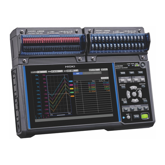
Page 25: Part Names And Functions; Screens
Part Names and Functions; Screens 1.2 Part Names and Functions; Screens LR8450/LR8450-01 Memory HiLogger Front Name Functionality Connector covers Inside each cover are connectors for plug-in modules. Affix the covers when not installing plug-in modules. p. 3 8 The covers can also be used as connector covers for plug-in modules. Display The instrument features a 7-inch TFT color LCD. – POWER Lights up when the instrument is on. p. 6 4 CHARGE Lights up when the instrument is charging. p. 4 4 ALARM Lights up when an alarm occurs. Instruction Manual Power key Turns the instrument on or off. - Page 26 Part Names and Functions; Screens Key controls Name Functionality WAVE Displays the waveform/value screen. Allows you Instruction to view waveforms and numerical values. Manual Displays the settings screen. Allows you to p. 7 0 configure function settings. FILE Displays the file screen. Allows you to perform Instruction file operations. Manual UNIT/SHEET keys Allows you to select the module or sheet and switches between sub tabs. p. 7 2 CHANNEL keys Switches channels. MONITOR Displays the monitor. Allows you to check the Instruction current input channel. Manual QUICK SET Launches the configuration navigator to display Instruction the connection guide. Manual Left Arrow,...
- Page 27 Part Names and Functions; Screens Rear Name Functionality Wireless certification Indicates the wireless certification number. (LR8450-01 only) – number Installation screw The screws can be used for attaching the Z5040 Fixed Stand, – holes which allows the product to mount on a wall. Warning Contains important information about the instrument. p. 4 0 Serial number The serial number consists of nine digits. The first two digits indicate the year of manufacture, while the second two digits indicate the month of manufacture. Do not remove this sticker as the number is important. – Communicate this number when you contact your authorized Hioki distributor or reseller. This label also indicates whether the instrument is an LR8450 or an LR8450-01. MAC address Indicates the MAC address assigned to your instrument. Do not – remove this sticker as the number is important. External control Indicates the names of the external control terminals on the left p. 6 3 terminal names side of the instrument.
- Page 28 Part Names and Functions; Screens Left side Right side Name Functionality Air vents Provides ventilation to keep the instrument from p. 9 reaching too high an internal temperature. External control terminals* Allows you to control the instrument using external signals. p. 6 3 Outputs alarm signals. Cable hook Pass the Z1014 AC Adapter’s cable through this hook p. 4 6 to keep it from being pulled out. AC Adapter connection Connect the included Z1014 AC Adapter here. p. 4 5 terminal USB cable connector Connect the included USB cable here.
- Page 29 Part Names and Functions; Screens Screen and icons Item Icon Description Media* An SD Memory Card has been inserted. p. 6 7 A USB Drive has been inserted. SCROLL Tapping the SCROLL/CURSOR keys moves the waveforms. CURSOR Instruction Manual Tapping the SCROLL/CURSOR keys moves the A/B cursors. Voltage No voltage is being output from the voltage output output* terminals. A voltage of 5 V DC is being output from the voltage output terminals. p. 6 1 A voltage of 12 V DC is being output from the voltage output terminals. A voltage of 24 V DC is being output from the voltage output terminals. Scaling Scaling is enabled for one or more channels. Instruction Manual *1: T he icon of media chosen as the priority save destination (left) and its available space (right) are displayed.
- Page 30 Part Names and Functions; Screens Item Icon Description Wireless The modules are connected in station mode. Instruction Manual The modules are disconnected in station mode. Instrument The instrument is being powered by the AC Adapter. p. 4 5 power* The instrument is operating on battery power (fully charged). The instrument is operating on battery power. The instrument is operating on battery power. The battery starts to run out. Connect the AC adapter to charge the battery. p. 4 0 The instrument is operating on battery power. The battery has run out. Connect the AC adapter to charge the battery. The instrument is being powered by the AC Adapter. The battery is being charged. A battery anomaly has occurred. Immediately stop the use of the instrument and remove the Battery Packs. *3: T wo icons will appear if two Z1007 Battery Packs have been inserted. The icon on the right indicates the status of the Battery Pack on the right when the instrument is viewed from the front (looking at the LCD screen), while the icon on the left indicates the status of the Battery Pack on the left.
-
Page 31: Plug-In Modules
Part Names and Functions; Screens Plug-in modules Figures show the U8550 Voltage/Temp Unit. Front Rear Bottom Name Functionality Input terminals Provides input terminals for each channel. p. 4 7 Terminal block cover Close the cover during measurement. – Connector Used for module expansion. p. 3 8 Attach the connector cover to any unused connectors. Serial number The serial number consists of nine digits. The first two digits indicate the year of manufacture, while the second two digits indicate the month of manufacture. Do not remove this sticker as – the number is important. Communicate this number when you contact your authorized Hioki distributor or reseller. If four plug-in modules have been installed Terminal block covers open toward you. -
Page 32: Wireless Modules
Part Names and Functions; Screens Wireless modules Figures show the LR8530 Wireless Voltage/Temp Unit. Front Rear Name Functionality CONNECT Indicates the status of communications with – the LR8450-01. Indicates an error state. – MEASURE Indicates the measurement status. – Lights up when the instrument is being powered by the AC Adapter or by an external – power supply. BATT Lights up when the instrument is operating on – battery power. CHARGE Lights up when the Battery Pack is being – charged. RESET Resets the wireless module’s communications – settings. AUTO Automatically configures communications settings between the LR8450-01 and the – wireless modules. Input terminals Provides input terminals for each channel. - Page 33 Part Names and Functions; Screens Right side Name Functionality Wireless LAN Adapter Connect the Z3230 Wireless LAN Adapter (wireless – module accessory) here. AC Adapter connection Connect the Z1008 AC Adapter (an included accessory) – terminal here. Serves as the function ground terminal. – POWER switch Turns the instrument on or off. – Serial number The serial number consists of nine digits. The first two digits indicate the year of manufacture, while the second two digits indicate the month of manufacture. Do not – remove this sticker as the number is important. Communicate this number when you contact your authorized Hioki distributor or reseller.
-
Page 34: Options
Options 1.3 Options There are a total of 10 measurement modules, including 5 plug-in modules and 5 wireless modules. For detailed specifications, see “10 Specifications” in the Instruction Manual. Plug-in modules Plug-in modules can be used with either the LR8450 or the LR8450-01. Number of Maximum Instrument name Measurement target channels sampling speed U8550 Voltage/Temp Unit Voltage, temperature 10 ms (thermocouple), humidity U8551 Universal Unit Voltage, temperature (thermocouple/ 10 ms resistance bulb), resistance, humidity U8552 Voltage/Temp Unit Voltage, temperature 20 ms* (thermocouple), humidity U8553 High Speed Voltage Unit Voltage 1 ms U8554 Strain Unit Voltage, strain 1 ms *: When using with 15 channels or less, 10 ms. -
Page 35: Other Options
Options Other options Z1014 AC Adapter (LR8450/LR8450-01 accessory) Z1008 AC Adapter (wireless module accessory) The LR8450/LR8450-01 ships with the Z1014 AC Adapter. Wireless modules ship with the Z1008 AC Adapter. These adapters allow the LR8450/LR8450-01 and wireless modules to be powered by commercial power. (AC power) • Rated supply voltage (100 to 240 V AC) • Rated power supply frequency (50/60 Hz) When using both the AC Adapter and Battery Pack, the AC Adapter has priority in powering the instrument or module. When power from the AC Adapter is interrupted, the instrument or module will immediately switch to battery power. Z1007 Battery Pack The optional Z1007 Battery Pack can be used to operate the instrument when commercial power, which enables through the AC Adapter the instrument to operate, cannot be used. In addition, it can be used as a backup power supply in the event of a power outage. See “Installing a Battery Pack” (p. 4 0). Z3230 Wireless LAN Adapter (wireless module... - Page 36 The optional C1012 Carrying Case provides a convenient way to transport the instrument. The C1012 can accommodate the logger (with up to four plug-in modules) as well as wireless modules (up to seven). Z4001 SD Memory Card (2 GB), Z4003 SD Memory Card (8 GB), Z4006 USB Drive (16 GB) You can save measurement data and settings to an SD Memory Card or USB Drive. Proper operation of the instrument with SD memory cards and USB drives other than options provided by Hioki is not guaranteed. SF4101/SF4102 Remote Measurement Service GENNECT Remote Hioki’s SF4101/SF4102 Remote Measurement Service (fees apply) allows you to control and download data from instruments installed in a remote location. The service offers the following functionality: • Remote monitor/remote logging function Download measured values from the instrument to the cloud and review them on a computer or smartphone. • License verification function Check the license expiration date, remaining data allowance, SD Memory Card capacity, and other information.
-
Page 37: Measurement Process
Prepare to use the instrument. See “2 Making Connections (Preparing for Measurement)” (p. 3 7). If using one or more plug-in modules, install them in the instrument. Connect either the AC Adapter or a charged Battery Pack and turn on the instrument and any wireless modules. Register any wireless modules (LR8450-01 only). Register any wireless modules you plan to use with the instrument (up to seven can be registered). Information about registered modules will be retained when the instrument is turned off. Prepare for measurement (placement and wiring). See “2.4 Connecting the Cables” (p. 4 7). Connect thermocouples, Humidity Sensors, and other components to the measurement modules’... -
Page 38: Making Connections (Preparing For Measurement)
Making Connections (Preparing for Measurement) This chapter describes how to prepare for measurement. Use either the AC Adapter or Battery Pack to power the instrument. You can rest secure in the event of an abrupt power outage by installing a Battery Pack even while using the AC Adapter. Install and connect modules and cables according to your measurement targets. You can choose either an SD Memory Card or a USB Drive as storage media. 2.1 Connecting Plug-in Modules ..........p. 3 8 2.2 Installing a Battery Pack ............p. 4 0 2.3 Connecting the AC Adapter ..........p. 4 5 2.4 Connecting the Cables............p. 4 7 Connecting voltage cables and thermocouples........ -
Page 39: Connecting Plug-In Modules
Connecting Plug-in Modules 2.1 Connecting Plug-in Modules You can connect up to four optional plug-in modules to one LR8450/LR8450-01. Add modules according to the number of channels necessary for measurement. WARNING Turn off the instrument and disconnect any cables before connecting or „ removing any plug-in modules. When not using a plug-in module slot, secure the connector cover over „ the instrument’s module connector with the screws. - Page 40 Connecting Plug-in Modules If installing multiple plug-in modules, do so as indicated in the diagram below. Do not remove the connector covers for any plug-in module slots not in use. When connecting 1 plug-in module When connecting 3 plug-in modules Connect the module to slot or Connect the modules to slots , and or , and Connecting plug-in modules as shown below will cause an error to be displayed on the screen. When connecting 2 or more plug-in modules When connecting 5 or more plug-in modules on one side IMPORTANT Plug-in modules ship with two spare screws (M3×35 mm). Exercise care not to lose them.
-
Page 41: Installing A Battery Pack
Do not solder a wire or other conductor directly to the Battery Pack. „ Do not connect the Battery Pack to any device not specified by Hioki. „ Do not use any Battery Pack that exhibits exterior damage or whose „... - Page 42 To operate the instrument or a wireless module on battery power, use „ only the Z1007 Battery Pack. Use of other batteries may damage the instrument or cause the Battery Pack to leak liquid, overheat, give off smoke, rupture, or ignite, resulting in serious bodily injury. Hioki is not liable for any equipment damage or accident resulting from use of a battery pack other than the Z1007. If you get electrolyte that has leaked from the Battery Pack in an eye, „ immediately wash the eye thoroughly with tap water or other clean water without rubbing and seek immediate medical attention.
- Page 43 Installing a Battery Pack IMPORTANT • Be sure to charge Battery Packs when using them for the first time after purchase or for the first time after an extended period of non-use. Battery Pack capacity declines due to self-discharge. • When operating time has become significantly shorter even though the Battery Pack was charged properly, the Battery Pack has reached its service life. Replace it with a new Battery Pack. • Connect Battery Packs to the instrument or wireless module correctly. • Charge Battery Packs within the ambient temperature range of 5°C to 35°C. Charging Battery Packs at a low temperature of close to 5°C will result in lower charge than at 23°C. The amount of time the instrument or wireless module can operate on the Battery Pack will decrease as the temperature falls. • When not using a Battery Pack for an extended period of time, remove it from the instrument or wireless module and store it at about 20°C. Charge each Battery Pack for about 30 min. with the instrument or a wireless module once a year. • Battery Packs are consumables. Each Battery Pack’s service life (defined as the period of time during which its capacity is at least 70% of the initial capacity) is about 300 charge/discharge cycles. (Service life varies with storage method and operating environment.) • For reasons related to Battery Pack characteristics, the indicated remaining battery life may diverge from the actual remaining battery life due to factors such as settings during use, operating temperature, and the number of battery charge/discharge cycles.
- Page 44 Installing a Battery Pack Installing the Battery Pack in the instrument The instrument can accommodate two Z1007 Battery Packs. One Battery Pack may be used alone. You will need: Z1007 Battery Pack, a Phillip’s head screwdriver (No. 2) Turn off the instrument and disconnect the AC Adapter and cable. Loosen the screw on the battery compartment on the rear of the instrument and remove the cover. Insert the Battery Pack perpendicularly and slide it toward the pins until it pushes up against the pins.
- Page 45 Installing a Battery Pack Charging the Battery Pack You can charge the Battery Pack by connecting the Z1014 AC Adapter to the instrument or the Z1008 AC Adapter to the wireless module. The Battery Pack will continue to be charged even while the instrument or the wireless module is turned off. (p.46) The CHARGE LED will turn orange while the Battery Pack is being charged. (On the instrument, the CHARGE LED will light up about 5 seconds after charging begins.) Charging will stop once the Battery Pack is fully charged, and the CHARGE LED will turn off. Rough charge time (LR8450/LR8450-01) • About 7 hr. (when charging a Battery Pack with little remaining battery life) Continuous operating time on Battery Pack power Instrument Approximate continuous operating time on one Battery Pack (reference value) Approximate continuous Backlight brightness operating time About 2 hr. 5 (maximum brightness) After being fully charged, with one U8551 Universal Unit connected, at an ambient temperature of 23°C Enabling the backlight saver or lowering the backlight brightness (dimming the backlight) will increase the operating time. See “Backlight saver” and “Backlight brightness” in the Instruction Manual. When using two Battery Packs, the instrument will be able to operate continuously for about twice as long as on one Battery Pack.
-
Page 46: Connecting The Ac Adapter
Connecting the AC Adapter 2.3 Connecting the AC Adapter The instrument ships with the Z1014 AC Adapter, while wireless modules ship with the Z1008 AC Adapter. Connect the power cord to the AC adapter and plug it into a power outlet. Be sure to use the included AC Adapter (with a grounded two-prong power cord). The optional Z1007 Battery Pack can be used to enable the instrument to continue operating in the event of a power outage. When using the AC Adapter with a Battery Pack, the AC Adapter has priority in powering the instrument. When power from the AC Adapter is interrupted, the instrument or module will switch to battery power. Be sure to read “Handling of cords and cables” (p. 4 7) before connecting the AC Adapter. In addition, turn off the instrument before connecting or disconnecting the AC Adapter. WARNING Use the included Z1014 AC Adapter (with a grounded 2-prong power „ cord) to operate the instrument on commercial power. Use the included Z1008 AC Adapter (with a grounded 2-prong power „... - Page 47 Connecting the AC Adapter Supplying power to the instrument with the AC Adapter (AC power) Connect the power cord to the Z1014 AC Adapter. Connect the AC Adapter’s output plug to the instrument. To keep the plug from being pulled out inadvertently, insert the AC Adapter’s output cord into the cable hook on the instrument.
-
Page 48: Connecting The Cables
Connecting the Cables 2.4 Connecting the Cables Pre-use inspection Inspect the instrument and wireless module before turning them on to check for damage during storage or shipping. If you find any damage, contact your authorized Hioki distributor or reseller. Inspection of peripheral equipment Do the measurement cables you’re about to connect have tears in their insulation, or is any metal exposed? If you find any damage, do not use the measurement cable. Doing so could cause electric shock. Replace the cable with the designated type. Inspection of the instrument • Does the instrument exhibit any damage? If you find any damage, have the instrument repaired. • When you turn on the instrument, does the screen work? If no screen is displayed, there may be a wiring break in the power cord, or the instrument may be damaged. Have it repaired. Handling of cords and cables WARNING Ensure measurement cables hang lower than the instrument. - Page 49 Connecting the Cables NOTICE Do not apply a voltage exceeding the specifications between channels. „ Modules whose channels are isolated from one another incorporate semiconductor relays. Subjecting these modules to a voltage exceeding the voltage specified in the instrument’s specifications could cause a short circuit fault of the semiconductor relays. IMPORTANT • Measurement may be affected by the EMC environment, for example external noise, when connecting cables of greater than 3 m in length. Keep cables away from power lines and ground lines. • Measured values may exhibit variability when cables are connected in parallel with other devices. Be sure to verify proper operation when connecting cables in parallel. When connecting cords to the analog input terminals DANGER Do not leave input cords connected in environments where there is the „...
- Page 50 Connecting the Cables When connecting cables to the external control terminals WARNING Before connecting cables to the external control terminals, follow the „ procedure below: 1. Turn off the instrument and all equipment to be connected. 2. Eliminate static electricity from the body. 3. Make sure that the signals do not exceed the rating of the external input/output. 4. Appropriately isolate the equipment to be connected Failure to do so could cause electric shock or damage to the instrument. NOTICE Do not short-circuit the output terminal or input a voltage to the output terminal. „...
-
Page 51: Connecting Voltage Cables And Thermocouples
Connecting the Cables Connecting voltage cables and thermocouples Connecting wires to a screw-type terminal block WARNING For screw-type terminal blocks, use specially designed screws to „ secure connections. Use of other screws could result in electric shock or equipment damage. Applicable modules: U8550, U8553, LR8530, LR8533 You will need: A Phillip’s head screwdriver (No. 2) and an input cable or thermocouple Recommended wire diameter Single-wire Diameter of 0.2 mm to 1.29 mm (AWG 32 to 16) Stranded wire 0.03 mm to 1.38 mm (AWG 32 to 16) Standard stripping length 10 mm Open the terminal block cover. Loosen the terminal block screw. - Page 52 Connecting the Cables Connecting wires to a push-button terminal block Applicable modules: U8551, U8552, U8554, LR8531, LR8532, LR8534 You will need: A flat-head screwdriver (with a tip width of 2.6 mm) and an input cable or thermocouple Recommended wire diameter Single-wire Diameter of 0.32 mm to 1.29 mm (AWG 26 to 16) Stranded wire 0.2 mm to 0.52 mm (AWG 24 to 20) Standard stripping length 9 mm Open the terminal block cover. Press down on the terminal button with the flat-head screwdriver. Cable insulation colors vary by country and manufacturer. Check before connecting. For more information about Strain Unit input terminals, see “(5) Voltage input” (p. 5 8). Remove the flat-head screwdriver from the button. The cable will be locked in place. Pull gently on the cable and verify that it does not come out.
-
Page 53: Connecting Resistance Bulbs
Connecting the Cables Connecting resistance bulbs Applicable modules: U8551, LR8531 You will need: A flat-head screwdriver (with a tip width of 2.6 mm) and a resistance bulb Recommended wire diameter Single-wire Diameter of 0.32 mm to 1.29 mm (AWG 26 to 16) Stranded wire 0.2 mm to 0.52 mm (AWG 24 to 20) Standard stripping length 9 mm Open the terminal block cover. Press down on the terminal button with the flat-head screwdriver. Insert the cable into the terminal hole while depressing the button. Three-wire type: Insert the cables into the positive terminal (red), negative terminal (black), and SoL terminal (black). -
Page 54: Connecting The Humidity Sensor
Connecting the Cables Connecting the Humidity Sensor Applicable modules: U8550, U8551, U8552, LR8531 You will need: A flat-head screwdriver (with a tip width of 2.6 mm) and the Z2000 Humidity Sensor Open the terminal block cover. Connect the Z2000 Humidity Sensor’s power cable to external control terminal voltage output terminal 1 or 2. Connect the red cable to the “VOUTPUT1” terminal or the “VOUTPUT2” terminal and the black cable to the “GND” terminal. To positive terminal of module External control terminal To negative terminal of module With the LR8531, you can connect the Humidity Sensor’s power cable to the module’s Z2000 Humidity Sensor power supply terminal. Connect the red cable to the positive terminal and the black cable to the negative terminal. To power terminal To positive terminal of module Black (ground) To negative terminal of module... - Page 55 Connecting the Cables NOTICE Do not use the Z2000 Humidity Sensor in locations with an excessive amount of „ dust or locations causing the instrument to get wet. Doing so could damage the Z2000 Humidity Sensor, which is not water-resistant or dust-resistant. • The Z2000 Humidity Sensor’s sensitivity and precision will degrade over time, even under normal operating conditions. To ensure measurement within the accuracy specifications, it is recommended to replace the sensor with a new model after one year of the first open of the sealed package. • If the conditions diverge from the indicated operating (storage) environment, the Z2000 Humidity Sensor’s precision may degrade in less than a year, making it incapable of accurate measurement. • In principle, placing the Z2000 Humidity Sensor in an environment where it would be exposed to organic gases (ketone, acetone, ethanol, toluene, etc.) may cause the sensor surface to become contaminated, increasing humidity measurement error.
-
Page 56: Connecting A Resistor
Connecting the Cables Connecting a resistor Applicable modules: U8551, LR8531 You will need: A flat-head screwdriver (with a tip width of 2.6 mm) and an input cable (for resistance measurement) Recommended wire diameter Single-wire Diameter of 0.32 mm to 1.29 mm (AWG 26 to 16) Stranded wire 0.2 mm to 0.52 mm (AWG 24 to 20) Standard stripping length 9 mm Open the terminal block cover. Press down on the terminal button with the flat-head screwdriver. Insert the cable into the terminal hole while depressing the button. Connect the resistor using a 4-wire setup (the instrument cannot measure 2- or 3-wire setups). -
Page 57: Connecting A Strain Gage Or Strain Gage-Type Converter
Connecting the Cables Connecting a strain gage or strain gage-type converter Applicable modules: U8554, LR8534 You will need: A flat-head screwdriver (with a tip width of 2.6 mm) and a strain gage or a strain gage-type converter Recommended wire diameter Single-wire Diameter of 0.32 mm to 1.29 mm (AWG 26 to 16) Stranded wire 0.2 mm to 0.52 mm (AWG 24 to 20) Standard stripping length 9 mm Ω Ω • Choose a strain gage whose gage resistance value is 120 . If you plan to use a 350 strain gage, add a separate bridge box and use the same connection as for the 4-gage method (converter). • Choose a strain gage-type converter that supports a bridge voltage of 2 V DC. NOTICE Do not bend, pull on, or twist cables, including where they connect, excessively. „... - Page 58 Connecting the Cables Open the terminal block cover. Set the DIP switch depending on the connection method. To set the DIP switch, see .“Setting the DIP switches for input connections” (p. 5 8) Press down on the terminal button with the flat-head screwdriver. Insert the cable into the terminal hole while depressing the button. To find target terminals to which cables are connected, see “Setting the DIP switches for input connections” (p. ...
- Page 59 Connecting the Cables Setting the DIP switches for input connections This section describes how to set the DIP switches for input connections. The dip switch is on in the upper position and off in the lower position. (1) 1-gage method (2-wire setup) (2) 1-gage method (3-wire setup) DIP switch DIP switch (3) 2-gage method (adjacent sides) (4) 4-gage method/converter DIP switch DIP switch OFF OFF (5) Voltage input When connecting a converter, the terminals function Negative Positive as indicated below. If the converter output utilizes a input input...
-
Page 60: Connecting Pulse Input
Connecting the Cables Connecting pulse input This section describes how to connect pulse input to the instrument’s external control terminals. You will need: A flat-head screwdriver (with a tip width of 2.6 mm) and an input cable (for pulse measurement) Recommended wire diameter Single-wire Diameter of 0.32 mm to 0.81 mm (AWG 28 to 20) Stranded wire 0.08 mm to 0.32 mm (AWG 28 to 20) Standard stripping length 10 mm Position the instrument so that the external control terminals on its side are facing you. Press down on the button for pulse 1 (or pulse 2 through 8) terminal with the flat-head screwdriver. -
Page 61: Connecting Alarm Output
Connecting the Cables Connecting alarm output This section describes how to connect alarm output to the instrument’s external control terminals. You will need: A flat-head screwdriver (with a tip width of 2.6 mm) and an output cable (alarm output) Recommended wire diameter Single-wire Diameter of 0.32 mm to 0.81 mm (AWG 28 to 20) Standard wire 0.08 mm to 0.32 mm (AWG 28 to 20) Standard stripping length 10 mm Position the instrument so that the external control terminals on its side are facing you. Press down on the button for alarm output 1 (or alarm output 2 through 8) terminal with the flat-head screwdriver. -
Page 62: Connecting Voltage Output
Connecting the Cables Connecting voltage output This section describes how to connect voltage output to the instrument’s external control terminals. The instrument can output a DC voltage for driving sensors. You can choose the output voltage. The maximum supplied current is 100 mA. • Voltage output terminal 1: 5 V, 12 V, 24 V • Voltage output terminal 2: 5 V, 12 V For more information about voltage output settings, see “8.1 Configuring Voltage Output (VOUTPUT)” in the Instruction Manual. You will need: A flat-head screwdriver (with a tip width of 2.6 mm) and an output cable (5 V to 24 V Recommended wire diameter Single-wire Diameter of 0.32 mm to 0.81 mm (AWG 28 to 20) Standard wire 0.08 mm to 0.32 mm (AWG 28 to 20) Standard stripping length 10 mm NOTICE Do not short the voltage output terminals and GND terminals. „ Once the output voltage has been set for the voltage output terminal, that voltage will be output as long as the instrument is turned on. Shorting the terminals in this state could damage the instrument. Do not apply a voltage from an external source to the voltage output terminals. „... - Page 63 Connecting the Cables Position the instrument so that the external control terminals on its side are facing you. Press down on the button for the voltage output terminal 1 or voltage output terminal 2 with the flat-head screwdriver. Insert the positive (+) cable into the terminal hole while depressing the button. Remove the flat-head screwdriver from the button.
-
Page 64: Connecting External Control Signals
Connecting the Cables Connecting external control signals This section describes how to connect external control signals to the instrument’s external control terminals. You can choose functions using external I/O. External input: You can control when to start and stop the instrument and input trigger signals. See “8.3 Configuring External Input/Output (I/O) Terminals” in the Instruction Manual. External output: You can output signals when a trigger is activated. See “Trigger output” in the Instruction Manual. You will need: A flat-head screwdriver (with a tip width of 2.6 mm) and an input cable (for pulse measurement) Recommended wire diameter Single-wire Diameter of 0.32 mm to 0.81 mm (AWG 28 to 20) Standard wire 0.08 mm to 0.32 mm (AWG 28 to 20) Standard stripping length 10 mm Position the instrument so that the external control terminals on its side are facing you. Press down on the terminal button with the flat-head screwdriver. Insert the cable into the terminal hole while depressing the button. -
Page 65: Turning The Instrument On And Off
Do not input a voltage or current to input terminals while the instrument or „ wireless module is off. Doing so could damage the instrument or wireless module. IMPORTANT • Be sure to turn off the instrument and any wireless modules after use. • The instrument and wireless modules will not malfunction in the event of a momentary power interruption lasting 40 ms or less. However, an interruption lasting longer than 40 ms will cause the instrument and wireless modules to malfunction. Check the condition of the power supply being used. In addition, you can continue measurement even in the event of an outage by using the Z1007 Battery Pack. See “2.2 Installing a Battery Pack” (p. 4 0). LR8450/LR8450-01 (1) Turning on the instrument Press the power key to turn on the instrument. The POWER LED will turn green. When the instrument starts up, the power icon will be shown on the bottom right of the screen. When the instrument is powered by the AC Adapter, the power plug mark will be displayed. When operating on battery power, the remaining battery life will be displayed. (2) Turning off the instrument Pressing the power key while the instrument is on will cause the instrument to display a message confirming whether you want to turn off the instrument. Choose [OK] and press the ENTER key to... -
Page 66: Sd Memory Card And Usb Drive
SD Memory Card and USB Drive 2.6 SD Memory Card and USB Drive You can save the instrument’s measurement data and settings to an SD Memory Card or USB Drive. You can also load previously saved data into the instrument to reproduce it. Use only the following Hioki options, which are more reliable than their commercial equivalents. Z4001 SD Memory Card (2 GB), Z4003 SD Memory Card (8 GB), Z4006 USB Drive (16 GB) See “3 Saving and Loading Data” in the Instruction Manual. WARNING Do not attempt to modify, disassemble, or repair an SD Memory Card or „ USB Drive yourself. Doing so may result in bodily injury or fire. Store SD Memory Cards and USB Drives out of reach of young children. - Page 67 SD Memory Card and USB Drive IMPORTANT • SD Memory Cards and USB Drives have a service life because they use flash memory. They lose the ability to store and load data after extended use. If you encounter this issue, purchase a new card or drive. • Hioki is not liable for data stored on SD Memory Cards and USB Drives, regardless of the nature or cause of the accident or damage involved. Data saved on SD Memory Cards and USB Drives may become unreadable after an extended period of time has passed. Be sure to back up any important data on SD Memory Cards and USB Drives. • Format new SD Memory Cards and USB Drives with the instrument prior to use. Using those formatted with a computer could prevent the real-time saving from keeping up with the measurement. • Verify that the write protect switch has been disengaged before inserting an SD Memory Card into the instrument. • Proper operation of the instrument is only guaranteed when using Hioki optional SD Memory Cards and USB Drives. Proper operation is not guaranteed with other recording media. • Observe the following to avoid loss or corruption of internally stored data: 1. Do not touch terminals or connection surfaces with your fingers or metallic objects. 2. Do not subject the instrument to vibration or mechanical shock or turn it off while writing or reading data. 3. Verify that SD Memory Cards and USB Drives do not contain important information (files) before initializing them. 4. Follow the procedure on the next page when removing the SD Memory Cards and USB Drives.
-
Page 68: Inserting And Removing Sd Memory Cards
SD Memory Card and USB Drive Inserting and removing SD Memory Cards Inserting an SD Memory Card Orient the SD Memory Card so that the ▲ mark is facing upward and insert it into the SD card slot. Insert the card until it locks in place with a clicking sound. Removing an SD Memory Card Check if measurement has stopped. -
Page 69: Inserting And Removing Usb Drives
SD Memory Card and USB Drive Inserting and removing USB Drives Inserting a USB Drive Align the plug of the USB Drive with the USB port of the instrument. Insert the USB Drive as far as it will go. Removing a USB Drive Verify that the instrument is not accessing the USB Drive (saving or writing data, etc.). Press the FILE key to display the FILE screen. -
Page 70: Settings And Operation
Settings and Operation This section provides basic instructions for how to operate the instrument. For more detailed information about settings, see “1 Settings and Operation” in the Instruction Manual. 3.1 Configuration Process ............p. 7 0 3.2 Basic Operation ..............p. 7 1 Switching among the main tabs ............. p. 7 1 Switching among the sub tabs ............... p. 7 1 Changing and accepting settings ............p. 7 2 Starting and stopping measurement ............ -
Page 71: Configuration Process
Configuration Process 3.1 Configuration Process Before starting measurement, you must set measurement conditions such as recording interval and range. You can save configured measurement conditions to media (an SD Memory Card or USB Drive). See “3 Saving and Loading Data” in the Instruction Manual. You can perform measurement using the same settings as in the past by loading previously saved measurement conditions. Settings are retained even when the instrument is turned off. Set the recording conditions. See “1.2 Setting Measurement Conditions” in the Instruction Manual. Press the key to display the [Measure] settings screen. Set the recording interval, recording time, and other parameters on the [Measure] settings screen. -
Page 72: Basic Operation
Basic Operation 3.2 Basic Operation This section provides basic instructions for how to operate the instrument. You can configure settings by operating the instrument’s keys. You can switch between main and sub tabs on the settings screens. See “1.1 Performing Basic Operations” in the Instruction Manual. In this manual, the active item is said to have “focus.” The background of the selected item will turn yellow. Switching among the main tabs Press the SET key to display the settings screen. You can switch among the following seven main tabs (listed at the top of the screen): [Unit], [Measure], [Channel], [Trigger], [Alarm], [Calculation], and [System]. You can switch among the main tabs using the Left Arrow and Right Arrow keys. You can move the focus among sub tabs by pressing the ENTER key. You can return the focus to the main tab by pressing the ESC key. You can also switch among the main tabs using the SET key. Unit Measure Channel Trigger Alarm Calculation System Switching among the sub tabs After selecting a main tab, you can switch the screen’s contents further with sub tabs (shown on the left side of the screen). Select the sub tab whose settings you wish to configure with the Up Arrow and Down Arrow keys. -
Page 73: Changing And Accepting Settings
Basic Operation Changing and accepting settings Select the setting you wish to configure with the Left Arrow, Right Arrow, Arrow, and Down Arrow keys. You can now configure the setting with focus (shown in yellow). Press the ENTER key. The available settings will be displayed. Select the desired setting with the Up Arrow Down Arrow keys and then press the ENTER key. -
Page 74: Starting And Stopping Measurement
Basic Operation Starting and stopping measurement Press the START key to start measurement. When the [System] > [Environment] > [Operation error prevention] setting is set to [ON], operation confirmation window will be displayed. Select [Yes] and press the ENTER key to start measurement. Starting measurement after stopping it will cause the measurement data in the instrument’s internal buffer memory to be deleted. Save important data on an SD Memory Card or USB Drive before starting measurement again. Press the STOP key to stop measurement. [Environment] [Operation error prevention] setting is set to [ON], When the [System] > > operation confirmation window will be displayed. Select [Yes] and press the ENTER key to stop measurement. • Measurement can also be stopped automatically at the set recording time. See “1.2 Setting Measurement Conditions” in the Instruction Manual. • You can prevent mistaken operation of the START and STOP keys. See “7.1 Configuring Settings” in the Instruction Manual. • You can start recording operation when specific conditions occur. This functionality is convenient when you wish to monitor conditions for anomalies. See “2 Trigger Function” in the Instruction Manual. Saving data You can save measurement data, settings, screen images, numerical calculation results, and other information with to storage media. -
Page 75: Resetting The System (Initialization)
Basic Operation Resetting the system (initialization) You can restore the settings to their factory defaults. When multiple people are using the instrument, special settings made by the last person to use the instrument may remain in effect. In such situations, it is recommended to perform a system reset. See “7.2 Controlling the System” in the Instruction Manual. Key lock (disabling keys) You can disable the instrument’s keys. This feature can be used to prevent accidental or unintended operation. You can disable the keys by pressing and holding the ESC key for at least 3 seconds. enabled] will be displayed on the screen. The message [Keylock Pressing a key will cause a message informing the user that the key lock is engaged to be displayed on the screen. You can disable the key lock by pressing and holding the ESC key again for at least 3 seconds. -
Page 76: Specifications
Specifications For detailed information on the instrument’s specifications, see “10 Specifications” in the LR8450/ LR8450-01 Instruction Manual stored on the accompanying CD. 4.1 Memory HiLogger Basic Specifications Operating Indoors, Pollution Degree 2, altitude up to 2000 m (6562 ft.) environment Operating −10°C to 50°C (14°F to 122°F), 80% RH or less (non-condensing) temperature and (Charging temperature range: 5°C to 35°C [41°F to 95°F]) humidity range Storage temperature −20°C to 60°C (−4°F to 140°F), 80% RH or less (non-condensing) and humidity range Power supply AC adapter Z1014 AC Adapter (12 V DC ±10%) AC Adapter rated supply voltage 100 V to 240 V AC (assuming voltage fluctuation of ±10%) AC Adapter rated power supply frequency 50 Hz/60 Hz Battery LR8450 accommodates 2 batteries. Z1007 Battery Pack (When used with AC Adapter, AC Adapter has priority.) Li-ion 7.2 V, 2170 mAh External power supply 10 V to 30 V DC... -
Page 77: Plug-In Module Specifications
Storage temperature −20°C to 60°C (−4°F to 140°F), 80% RH or less (non-condensing) and humidity range Maximum input ±100 V DC voltage Maximum channel-to- ±300 V DC channel voltage Maximum rated 300 V AC, DC (Measurement Category II) terminal-to-ground Between any input channel (+, −) and the instrument (LR8450/LR8450-01) or between voltage any two modules Anticipated transient overvoltage: 2500 V U8551 Universal Unit Operating Indoors, Pollution Degree 2, altitude up to 2000 m (6562 ft.) environment Operating −10°C to 50°C (14°F to 122°F), 80% RH or less (non-condensing) temperature and humidity range Storage temperature −20°C to 60°C (−4°F to 140°F), 80% RH or less (non-condensing) -
Page 78: U8552 Voltage/Temp Unit
Storage temperature −20°C to 60°C (−4°F to 140°F), 80% RH or less (non-condensing) and humidity range Maximum input ±100 V DC voltage Maximum channel-to- ±300 V DC channel voltage Maximum rated 300 V AC, DC (Measurement Category II) terminal-to-ground Between any input channel (+, −) and the instrument (LR8450/LR8450-01) or between voltage any two modules Anticipated transient overvoltage: 2500 V U8553 High Speed Voltage Unit Operating Indoors, Pollution Degree 2, altitude up to 2000 m (6562 ft.) environment Operating −10°C to 50°C (14°F to 122°F), 80% RH or less (non-condensing) temperature and humidity range Storage temperature −20°C to 60°C (−4°F to 140°F), 80% RH or less (non-condensing) -
Page 79: U8554 Strain Unit
Plug-in Module Specifications U8554 Strain Unit Operating Indoors, Pollution Degree 2, altitude up to 2000 m (6562 ft.) environment Operating −10°C to 50°C (14°F to 122°F), 80% RH or less (non-condensing) temperature and humidity range Storage temperature −20°C to 60°C (−4°F to 140°F), 80% RH or less (non-condensing) and humidity range Maximum input ±0.5 V DC voltage Maximum channel-to- Non-isolated (all channels share common GND) channel voltage Maximum rated 30 V rms AC or 60 V DC (between analog input channels and the instrument [LR8450/ terminal-to-ground LR8450-01]) voltage Anticipated transient overvoltage: 330 V... -
Page 80: Maintenance And Service
WARNING Do not attempt to modify, disassemble, or repair the instrument or „ measurement modules yourself. High voltages are present in certain parts of the instrument and measurement modules. Attempting the above may cause electric shock or fire. Replaceable parts and service life Some parts used in the instrument are characterized by performance that degrades over years of use. It is recommended to replace these parts regularly to ensure instrument functionality over the long term. To order replacements, please contact your Hioki distributor. Part service life varies with the operating environment and frequency of use. These parts are not guaranteed to operate throughout the period defined by the recommended replacement interval. Recommended Part Remarks replacement interval Electrolytic capacitors About 10 years Boards with these components must be replaced. LCD backlight About 100,000 hr. - Page 81 Pack the instrument in the packaging in which it was initially delivered. „ Double-pack the instrument. „ Failure to do so could cause damage during shipment. When sending the instrument to be repaired, attach a description of the issue. Hioki is unable to guarantee that instruments will not be damaged during shipment. When transporting the Z1007 Battery Pack on an aircraft • The Z1007 Battery Pack uses rechargeable lithium-ion batteries. • The transport of lithium-ion batteries by air is subject to regulations in accordance with United Nations recommendations. • If you need transport any device that uses the Z1007 Battery Pack by air, contact your authorized Hioki distributor or reseller for instructions.
-
Page 82: Troubleshooting
Troubleshooting 5.2 Troubleshooting This section describes what to check when you have a problem and suggests possible solutions. Before sending the instrument to be repaired If you believe your instrument might be damaged or malfunctioning, check the following information before contacting your authorized Hioki distributor or reseller. Symptom Check items Solutions Nothing is • Has the power cord been disconnected? Properly connect the power cord. displayed on the (p. 4 6) screen when I • Has the Battery Pack been properly Properly install the Battery Pack if it is press the POWER installed? improperly installed. (p. 4 3) button. The instrument • Does the Battery Pack have any remaining Charge the Battery Pack. won’t turn on. - Page 83 Troubleshooting Symptom Check items Solutions I can’t save data • Is Hioki optional media being used? Use a Hioki optional SD Memory Card or to storage media USB Drive. (SD Memory Proper operation of the instrument with Card, USB Drive). SD memory cards and USB drives other than options provided by Hioki is not guaranteed. • Has the media been inserted properly? Insert the media properly. (p. 6 5) • Has the media been formatted (initialized)? Format media when using it for the first time. (See “3.2 Formatting Media” in the Instruction Manual.) • Is there enough available space left on the Format or switch media. media? • Are there more than 1000 files in the Keep the number of files stored in every folder? folder to a maximum of 1000. If a folder • The file screen can display a maximum of contains an excessive number of files, it 1000 files.
-
Page 84: Error Messages
Troubleshooting Error messages There are two types of error message: errors and warnings. Errors encountered by the instrument are displayed on the screen. Use the tables shown below to check the nature of the error and review suggested solutions. Error messages Message Solutions ERR_BT01 Internal temperature of the instrument is Check the operating temperature abnormal. environment and verify that the fan is After saving the necessary data, turn off the operating. power. If this message is displayed while using the instrument within the operating temperature range, have it repaired. ERR_SY01 Program failure. Repair required. Turn off the instrument and have it repaired. ERR_SY02 Unit connection error. Verify that the measurement module is Current unit configuration is not valid. properly connected. Please review the connection. ERR_SY03 The battery has been removed. Check the Battery Pack connection. ERR_SY04 Clock correction circuit error. Repair Turn off the instrument and have it repaired. required. ERR_SY05 Update failed Turn off the instrument and repeat the update. - Page 85 Troubleshooting Message Solutions ERR_FL06 Media is full or cannot delete oldest wave The file was not able to be stored file because the SD Memory Card or the USB Drive starts to run out of space. Delete unnecessary files to free up space. Alternatively, switch media. ERR_FL07 This folder cannot be deleted or renamed This message is displayed to prevent on the instrument. accidental deletion of data folders. Use a computer to delete or rename folders. ERR_FL08 Confirm the A-B cursor position The A/B cursors are inappropriately placed (for example, outside the waveform range). Check the positions of the A/B cursors. ERR_FL09 File is damaged The file cannot be loaded because the information in it is damaged. Load an appropriate file. ERR_FL10 Duplicate name. Enter a unique file name. ERR_FL11 This folder/file is protected. Folders and files with the read-only attribute cannot be deleted using the instrument. Use a computer to delete. Warning messages • Press any key to clear the display. Message Solutions WARN_BT01 Internal temperature of the instrument is...
- Page 86 Troubleshooting Message Solutions WARN_FL01 Storage media not found. Insert an SD Memory Card or a USB Drive. WARN_FL02 Firmware update not possible due to low Updating the instrument is prohibited if the battery. battery starts to run out. Provide power to Connect the AC adapter and try again. the instrument using the AC adapter or an external power supply. Alternatively, charge the battery sufficiently. WARN_FL03 Firmware update not possible due to weak Check if the wireless modules are on. signal conditions. Check the state of communications with the Improve the communication environment wireless modules. If the communications and try again. are disrupted, move the equipment to improve the communications state. WARN_FL04 The firmware cannot be updated because Updating the instrument is prohibited if the the battery of the wireless unit is low. battery of the wireless modules starts to Connect the AC adapter and try again. run out. Connect the AC adapter before updating the instrument. WARN_FL06 Insert SD memory card or USB flash drive. Insert an SD Memory Card or a USB Drive. WARN_FL07 Storage media is almost full The media starts to run out of space. Switch media.
- Page 87 Troubleshooting Message Solutions WARN_FTPC01 FTP data transfer failed. File not found. Manually obtain files that have not transferred from the instrument with the FTP. Alternatively, load files from the media set as the destination location. MSG_FL10 The directly connected unit and settings The connected plug-in modules do not data do not match. match the plug-in modules configuration Do you want to restore the backed up data? saved in the loaded setting data. Check the configuration of the connected plug-in modules. MSG_SU04 The text format cannot be selected with the If you wish to save data in text format, use current recording interval settings. a longer recording interval. If you do not wish to change the recording interval, save data in binary format. See “1.2 Setting Measurement Conditions” in the Instruction Manual. MSG_SU05 CSV auto save has been set. Specified If you wish to use a shorter recording record interval not configurable. interval, save data in binary format. If you cannot switch to text format, use a longer recording interval. See “Auto save (real-time save)” in the Instruction Manual. MSG_SU06 10ms recording interval cannot be If there are too many channels for which configured. Number of channels exceeding measurement is enabled, you will not be the limit in use.
- Page 88 Troubleshooting Message Solutions – Pre-trigger time and settings modified Changing the recording interval or recording time may shorten the time that can be set for the pre-trigger. Check the updated pre-trigger settings. – Trigger or alarm setting value of this channel The trigger or alarm settings have changed. modified Check the updated settings. See “2.2 Enabling the Trigger Function” and “4.1 Configuring Alarms” in the Instruction Manual. – Burn-out settings modified The wire break detection function has been set to [OFF]. To use the wire break detection function, either increase the recording interval or reduce the number of channels being measured. See “1.2 Setting Measurement Conditions” in the Instruction Manual. – Cannot activate Burn Out (broken-wire) The user-specified setting does not support detection. Set the unit update interval to the wire break detection. automatic or a rate slower than current Set the data refresh interval to [Auto] or an settings. interval longer than that presently set. See “1.2 Setting Measurement Conditions” in the Instruction Manual. – File partition period modified Changing the recording interval will cause the segment time to change. Check if the settings are appropriate.
- Page 89 Troubleshooting Message Solutions – Division time for numerical calculation The [Split time] setting under [Numerical modified calculation] was changed because the recording interval was changed. Check if the settings are appropriate. See “Measurement operation” in the Instruction Manual. – Recording time settings modified The recording time was changed because the recording interval was changed. Check if the settings are appropriate. See “Measurement operation” in the Instruction Manual. – File rename failed The filename cannot be changed. Check whether there’s another file with the same name. – Copy file failed The file cannot be copied. Check whether there’s another file with the same name. – Delete file failed The file cannot be deleted. Verify that the media’s write protect switch has been disengaged. – Format media failed The media cannot be formatted (initialized). Verify that the media’s write protect switch has been disengaged. –...
- Page 90 Troubleshooting Message Solutions – Scaling conversion error. Any attempts to configure a disabled scaling setting may cause this message to appear. (Example: Attempting to set the scaling slope at zero) Set an appropriate figure. – Cannot set to text format. Set the recording The user-specified setting does not support interval to [20 ms] or more. text-format saving of waveform data. Set the recording interval at [20 ms] or longer. – Cannot set to text format. Set the recording The user-specified setting does not support interval to [10 ms] or more. text-format saving of waveform data. Set the recording interval at [10 ms] or longer. – Recording interval cannot be changed. Set The user-specified setting does not support waveform data storage format to binary a recording interval of less than [10 ms]. format. Set the saving format to binary. Alternatively, reduce the number of measurement channels. – Waveform data storage format has been The number of channels to be measured changed to binary format. exceeds the upper limit supported by the user-defined recording interval. To save data in text format, use the longer recording length, or reduce the number of channels to be measured.
-
Page 91: Disposing Of The Instrument
Disposing of the Instrument 5.3 Disposing of the Instrument The instrument has a built-in backup lithium battery. When disposing of the instrument, remove the lithium battery and dispose of it in accordance with local regulations. WARNING Turn off the power button and disconnect the power cord and all cables „ before removing the lithium battery. Failure to do so could cause electric shock. Store the removed lithium battery out of reach of children. „... -
Page 92: Faq
FAQ (Frequently Asked Questions) 5.4 FAQ (Frequently Asked Questions) Installation and measurement operation Question Answer How long can the instrument operate The instrument can operate for about 2 hours “Continuous on battery power? on one fully charged Z1007 Battery Pack, or for operating time on about 4 hours on two fully charged Battery Packs. Battery Pack power” (Reference value at 23°C) (p. 4 4) What will happen to data if the power No measurement data will remain. Against a “2.2 Installing a goes out during measurement? power failure, using the Z1007 Battery Pack is Battery Pack” recommended. (p. 4 0) Can I resume recording once the Recording can be resumed when the power comes See “7.1 Configuring power comes back on? back on by using the start state retention function. Settings” in the Instruction Manual. - Page 93 Triggers Question Answer The instrument is displaying the When a trigger has been set, recording will not See “2 Trigger message [Waiting for trigger...], and start until the trigger conditions are satisfied. If the Function” in the it won’t make measurements. trigger setting is off, you can start recording by Instruction Manual. pressing the START key. Saving data Question Answer Can I use any commercially available Use only Hioki optional SD Memory Cards or USB SD memory card or USB drive? Drives. Proper operation is not guaranteed when – using commercially available SD memory cards USB drives. USB drives with security functions such as – fingerprint authentication cannot be used. Can I switch media while auto save is Choose [Eject] on the top right of the waveform See “Replacing in progress? screen and press the ENTER key. (ejecting) media during real-time save operation” in the Instruction Manual. For how many days can the instrument Available recording length settings are determined See “11.8 File Size”...
-
Page 94: Open-Source Software
Open-source software 5.5 Open-source software This instrument includes software to which GNU General Public License GNU Lesser General Public License and other licenses are applied. You have the right to obtain, modify, and redistribute the source code of the software under these licenses. For details, visit the following website. https://www.hioki.com/en/support/oss Hioki would prefer you not to direct any inquiries on the content of the source cord. -
Page 95: Index
Index ............ A/B cursors Instruction Manual Horizontal axis display Instruction Manual ........ AC Adapter ............33 HTTP server Instruction Manual Accessories ..............4 Humidity Sensor ..........33 Alarm output ......60 Instruction Manual ........Alarms Instruction Manual ........Auto save Instruction Manual Icon ................27 Initialization ........ 74 Instruction Manual ......Input channels Instruction Manual ...... Backlight brightness Instruction Manual Inspections ............... - Page 96 Index ......Real-time save Instruction Manual Z1007 ..............33 ....... Replacing media Instruction Manual Z1008 ..............33 Repairs ............... 79 Z1014 ..............33 ......Resistance bulbs ............52 Zero adjustment Instruction Manual Resistors..............55 Saving data........ 73 Instruction Manual ........Scaling Instruction Manual SD card slot .............. 26 SD Memory Cards ..........34 Serial number ..........25 Service life ..............
Need help?
Do you have a question about the LR8450 and is the answer not in the manual?
Questions and answers