Advertisement
- 1 Introduction
- 2 Inspection/Maintenance
- 3 Operating Precautions
- 4 Safety Information
- 5 Overview
- 6 Specifications
- 7 Part Names
- 8 Accessories
- 9 Connection Method
- 10 Fixing Using
- 11 Zero Adjustment
- 12 Replacing the Used Tip Pin
- 13 Four-terminal Pair Method
- 14 Warranty Certificate
- 15 Documents / Resources
Introduction
Thank you for purchasing the HIOKI L2003 Pin Type Probe. To obtain maximum performance from the product please read this manual first, and keep it handy for future reference.
Inspection/Maintenance
When you receive the product, inspect it carefully to ensure that no damage occurred during shipping. If damage is evident, or if it fails to operate according to the specifi cations, contact your authorized Hioki distributor or reseller.
Preliminary checks

Before using the product, ensure that the insulation on the probes are not damaged and conductors are not exposed. Using the product in such conditions could cause an electric shock, so contact your authorized Hioki distributor or reseller for repair.
Maintenance and service

Never use cleaning agents containing benzene, alcohol, acetone, ether, ketones, thinners or gasoline. These can deform and discolor the case.
- To clean the product, wipe it gently with a soft cloth moistened with water or mild detergent.
- If the product seems to be malfunctioning, contact your authorized Hioki distributor or reseller. Pack the product so that it will not get damaged during shipping, and include a description of existing damages. Hioki cannot be responsible for damage that occurs during shipment.
Disposal
Handle and dispose of the product in accordance with local regulations.
Operating Precautions
Installing the product in inappropriate locations may cause the probe to malfunction or lead to accidents. Please do not install in the following locations. For details on the operating temperature and humidity, see the specifi cations.

- Exposed to direct sunlight or high temperatures
- Exposed to corrosive or combustible gases
- Exposed to strong electromagnetic fi elds or electrostatic charges
- Near induction heating systems (such as high-frequency induction heating systems and IH cooking equipment)
- Susceptible to vibration
- Exposed to water, oil, chemicals, or solvents
- Exposed to high humidity or condensation
- Exposed to high quantities of dust particles

- The ends of the probes are sharp. Be careful to avoid injury.
![]() To prevent probe damage, do not step on probes or pinch them between other objects. Do not bend or pull on probes at their base.
To prevent probe damage, do not step on probes or pinch them between other objects. Do not bend or pull on probes at their base.
Safety Information
Before using the product, be certain to carefully read the following safety notes.
- Customers are not allowed to modify, disassemble, or repair the instrument. Failure to observe these precautions may result in fire, electric shock, or injury.
- Ensure that the input does not exceed the maximum input voltage or current to avoid product damage resulting from heat building. Excessive voltage and current can cause the product to malfunction.
- Mishandling could result in malfunction of the probe. Be certain that you understand the instructions and precautions in the manual before use.
- If persons unfamiliar with electricity measuring product are to use the product, another person familiar with such instruments must supervise operations.
Safety symbols
 Indicates cautions and hazards. When the symbol is printed on the product, refer to a corresponding topic in the Instruction Manual. Indicates cautions and hazards. When the symbol is printed on the product, refer to a corresponding topic in the Instruction Manual. |
 Indicates DC (Direct Current). Indicates DC (Direct Current). |
 Notation
In this manual, the risk seriousness and the hazard levels are classifi ed as follows.
| | Indicates a potentially hazardous situation that may result in death or serious injury to the operator. |
| | Indicates a potentially hazardous situation that may result in minor or moderate injury to the operator or damage to the product or malfunction. |
| | Indicates information related to the operation of the product or maintenance tasks with which the operators must be fully familiar. |
| | Indicates a prohibited action. |
| | Indicates actions which must be performed. |
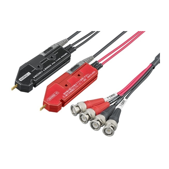
Overview
L2003 Pin Type Probe is a four-terminal probe. The probe can be used to contact various types of batteries since the measuring unit is pin shaped.
Specifications
| Measurable frequency range | DC to 1050 Hz |
| Maximum rated voltage 30 V peak | |
| Maximum rated current 2.5 A peak | |
| Structure | Four-terminal pair connection structure |
| Length | Approx. 1500 mm (59.06') |
| Mass | Approx. 200 g (7.1 oz.) |
| Cable used | 50 Ω Coaxial cable |
| Terminal structure | Gold plating process Tip shape: Needle Used tip pin can be replaced. |
| Distance between pins 2.5 mm (0.10') | |
| Operating temperature and humidity | Temperature; 0°C to 40°C (32°F to 104°F), Humidity; 80% RH or less (no condensation) |
| Storage temperature | Temperature; -10°C to 50°C (14°F to 122°F) |
| and humidity | Humidity; 80% RH or less (no condensation) |
| Operating environment Indoors, Pollution degree 2 altitude up to | 2000 m (6562 ft.) |
| Product warranty period | 1 year |
| Accessories | Return Cable (400 mm) Return Cable (550 mm) Return Cable (800 mm) Instruction Manual |
| Option | 9772-90 Tip Pin |
Part Names
Probe's maximum rating is 30 V, but be careful to avoid exceeding the maximum rating of the measuring instrument.

Return Cable (550 mm) is shipped in a state connected to the instrument.
Accessories

Connection Method
Clean the tip of the tip pin and the surface of the measuring object before zero adjustment and measurement.
Connecting to the instrument

Connecting the return cable
- Connect the return cable before measurement.
- Adjust the fixed position of the probe so that the return cable between the probes does not sag.
- Securely insert the plug of the return cable up to the back of the probe (both red and black).

- Arrange the probes so that the distance between the pin tips of the probe is the same as that between the terminals of the actual measuring object, with the SENSE sides of the probes (both red and black) facing inwards.

- Adjust the position of the probes such that the return cable between the probes does not sag, and fix by pushing the return cable into the grooves of the probes.


When viewed from the front

When viewed from the rear

(The return cable is indicated black in the illustration above.)
Use a cable of suitable length for the distance between the terminals of the measuring object from the three types of accessory cables.
| Return cable length | Distance between the terminals of the measuring object |
| 400 mm | 100 mm or less |
| 550 mm (mounted before shipment) | 100 mm to 250 mm |
| 800 mm | 250 mm to 500 mm |
Fixing Using
The probe can be fixed using the mounting holes. (Please prepare your own jig or equipment to fix.) Hole diameter: 3.2 mm, use a M3 screw.

Zero Adjustment
Execute the zero adjustment using the zero adjustment board provided with the connected instrument. Insert the tip pins of the probes into through holes having the same width as the terminals of the measuring object, and carry out the zero adjustment with the connected instrument.

- Adjust the return cable between the terminals so that it does not sag.
- If there is no through hole with the same width as the terminals of the measuring object, perform zero adjustment with the most nearest width scale of the through hole as the terminals.
- Perform zero adjustment by facing the probe's (both red and black) SENSE side inwards.
Replacing the Used Tip Pin
Replace the used tip pin with a new one when the tip pin breaks or is worn out. To purchase Model 9772-90 Tip Pin for replacement, contact your authorized Hioki distributor or reseller.
<Tools to be prepared> Model 9772-90 Tip Pin, pliers, etc.
- Turn off the power to the connected instrument and remove the return cables of the probes.

- Grip the tip pin to be replaced with pliers and pull it out.

- Insert a new tip pin in the socket, and securely push to the back by pressing with a hard board so that the tip pin does not fl y out.
![]()
- Measure a known measuring object to check if the measured value is correct.


Four-terminal Pair Method
L2003 uses the four-terminal pair method as the measurement method.
Four-terminal pair method
In the four-terminal pair method, the current fl ows backward (current returns) with the same magnitude as the measuring current in the shields of the SOURCE cables, and then cancels the magnetic fi eld of the measuring current. This method suppresses the induced electromotive force induced at the SENSE terminals, and detects the voltage actually generated in the object being measured.
Four-terminal pair method when using the optional probe
When the L2003 is used, the four-terminal pair method is structured as described below. Vicinity of the measurement object will not entirely be four-terminal pair, and will be affected by an inductive magnetic field. The shape of the return cable should not be changed, and kept away from metals when use. (When there are metals, inductive magnetic field occurs due to eddy current, and leads to measurement errors.)

- Keep the loop area between the return cable and measurementobject as small as possible.
- Keep the loop shape and wiring position always the same.
- Keep away from metals.
When the measurement value fluctuates
Keep the return cable in shape, or the affects of the magnetic field changes and the measurement value may flactuate.
Twist the return cable to keep a fixed shape.
(The return cable is indicated black in the illustration.)

Warranty Certificate
This product passed a rigorous inspection process at Hioki before being shipped.
In the unlikely event that you experience an issue during use, please contact the distributor from which you purchased the product, which will be repaired free of charge subject to the provisions of this Warranty Certificate. This warranty is valid for a period of one (1) year from the date of purchase. If the date of purchase is unknown, the warranty is considered valid for a period of one (1) year from the product's date of manufacture.
Please present this Warranty Certificate when contacting the distributor.
Accuracy is guaranteed for the duration of the separately indicated guaranteed accuracy period.
Visit us at www.TestEquipmentDepot.com

Documents / Resources
References
Download manual
Here you can download full pdf version of manual, it may contain additional safety instructions, warranty information, FCC rules, etc.
Advertisement


Need help?
Do you have a question about the L2003 and is the answer not in the manual?
Questions and answers