Table of Contents
Advertisement
Quick Links
LR8400-92
LR8400-93
PV Power Verifier
Instruction Manual (PV Mode)
December 2013 Revised edition 1
Printed in Japan
LR8400E981-01 13-12H
Measurement Procedure
Turn on the instrument.
1. Select "PV Mode Set ON" on the Settings screen.
2. Connect the sensors to the LR8400-23.
3. Place the sensors (when investigating a failed string, change the measurement
circuit inside the junction box).
End recording.
Check and analyze saved data.
Turn off the instrument.
1. Select "PV Mode Set ON" on the Measurement Settings screen.
-1. Press the "SET" key and select "PV Mode Set ON" on the
Measurement Settings screen.
2. Connect the sensors to the LR8400-23.
-1. Ch.1-1:
• Connect the BNC conversion cable(2.4m) to the BNC side of the 9322 Differential Probe and connect
the 9804-01 Magnet Adapter (red) and the 9804-02 Magnet Adapter (black) to the ends.
• Connect the BNC conversion cable to Ch.1-1.
• Connect the power cord to the power jack on the 9322 Differential Probe.
• Connect the power cord's positive wire to the +12 V jack on the external I/O terminal block on the LR8400-23, and similarly
connect the power cord's negative wire to the GND jack.
-2. Ch.1-2:
• Connect another BNC conversion cable(30cm) to the CT9692-90 (or CT9693-90) Clamp Sensor and connect it to Ch.1-2.
• Set the CT6590 Sensor Unit's range (H or L).
• Check the AA batteries in the CT6590 Sensor Unit.
-3. Ch.1-3:
• Connect the actinometer (EKO Instruments ML-01 or ML-020VM).
-4. Ch.1-4:
• Connect the thermocouple.
3. Place the sensors (see Figures 1 and 2).
-1. Ch.1-1:
• Connect the 9804-01 (red) and 9804-02 (black) magnet adapters that are connected to the tip of the 9322 Differential Probe to the
positive and negative terminals of the main DC line in the junction box or the electrical box (or when investigating a failed string,
the branch circuit) between the solar panels and the power conditioner. Cut the magnet sheet, pasted on the back of the 9322
Differential Probe.
-2. Ch.1-2:
• Clamp the CT9692-90 (or CT9693-90) Clamp Sensor to the positive side of the main DC line in the junction box or electrical box
(or when investigating a failed string, the branch circuit). At this time, orient the current direction mark on the clamp sensor so that
it indicates a flow from the solar panels to the power conditioner.
-3. Ch.1-3:
• Attach the actinometer (EKO Instruments ML-01 or ML-020VM) to the solar panel. So that it is parallel with the measurement
surface using the adjustment screw.
-4. Ch.1-4:
• Attach the thermocouple to the solar panel.
Thank you for choosing the Hioki LR8400-92/
LR8400-93. This Measurement Guide introduces the
basic method for measuring the DC side of a
photovoltaic system. For more information about
standard methods for using the instrument in
applications other than the above and general handling
information, please see the LR8400-20 Instruction
Manual.
End measurement.
Measurement preparations
-1. Inspect the instrument.
-2. Insert a CF card (or USB flash drive)
into the instrument as necessary.
-3. Connect the AC adapter.
-4. Turn on the instrument.
Figure 1
Figure 2
1
Advertisement
Table of Contents

Related Manuals for Hioki LR8400-92


Summary of Contents for Hioki LR8400-92
- Page 1 LR8400-92 Thank you for choosing the Hioki LR8400-92/ LR8400-93 LR8400-93. This Measurement Guide introduces the basic method for measuring the DC side of a PV Power Verifier photovoltaic system. For more information about Instruction Manual (PV Mode) standard methods for using the instrument in...
- Page 2 4. Configure settings. -1. Select the “PV Mode Set ON” setting on the Measurement Settings screen. Note: version software until the V9.12, it was ML-020 only rather than selection of pyranometer kind. From V9.13, please use it to select "ML-01", "ML-020", and "Free Set"...
- Page 3 5. Check measured values on the Monitor screen. -1. If you encounter any of the following displays on the Monitor screen, refer to the indicated solution. Display Solution • Check whether the 9322 Differential Probe switch is set to “DC.” Erroneous voltage value •...
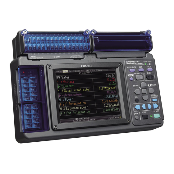
- Page 4 About the Waveform/Values screens PV Wave + Value screen The instrument provides the following six Waveform/Values screens: •PV Wave + Value Estimate Power screen •PV Wave + Crsr •Gauge + PV Wave •PV Value •Estimate Power •AC Estimate (reference values) Equations w1: Power (kW) = Voltage (Ch.
Need help?
Do you have a question about the LR8400-92 and is the answer not in the manual?
Questions and answers