Hioki LR8450 Quick Start Manual
Memory hilogger
Hide thumbs
Also See for LR8450:
- Instruction manual (425 pages) ,
- Quick start manual (96 pages) ,
- Instruction manual (2 pages)
Table of Contents
Advertisement
Quick Links
LR8450
LR8450-01
MEMORY HiLOGGER
Be sure to read this manual before using the instrument.
When using the instrument for the first time
Convenient Functionality
Part Names and Functions; Screens
Making Connections (Preparing for Measurement)
Settings and Operation
Dec. 2020 Revised edition 2
LR8450A963-02 20-12H
p.13 Maintenance and Service
p.23 Error messages
p.37 FAQ
p.75
HIOKI LR8450A963-02
Quick Start Manual
Troubleshooting
p.6
p.93
p.97
p.107
EN
Advertisement
Table of Contents

Related Manuals for Hioki LR8450


Summary of Contents for Hioki LR8450
- Page 1 LR8450 LR8450-01 Quick Start Manual MEMORY HiLOGGER Be sure to read this manual before using the instrument. p.6 When using the instrument for the first time Troubleshooting Convenient Functionality p.13 Maintenance and Service p.93 Part Names and Functions; Screens p.23 Error messages...
- Page 2 HIOKI LR8450A963-02...
-
Page 3: Table Of Contents
..........21 Starting and stopping measurement ..79 Part Names and Functions; ......80 Formatting storage media Screens ..........23 ..........81 Saving data LR8450/LR8450-01 Memory HiLogger ..23 ..........81 Loading data Plug-in modules ........30 .....82 Initialization (resetting the system) Wireless modules ........31 Key lock (disabling keys) ......82... - Page 4 Contents Disposing of the Instrument ....106 (Frequently Asked Questions) ..107 Open-source software .......110 Index Warranty Certificate HIOKI LR8450A963-02...
-
Page 5: Introduction
Introduction Introduction Thank you for choosing the Hioki LR8450/LR8450-01 Memory HiLogger. To ensure your ability to get the most out of this instrument over the long term, please read this manual carefully and keep it available for future reference. The LR8450-01 Memory HiLogger adds wireless LAN functionality to the LR8450. -
Page 6: About The Notations Used In This Manual
“Operating Precautions” that comes with the instrument. Indicates an instrument that has been protected throughout. Indicates whether the power is on or off. Indicates the ground terminal. Indicates direct current (DC). Indicates alternating current (AC). HIOKI LR8450A963-02... - Page 7 Example: 20 Ms/s (20 megasamples per second) signifies 20×10 samples per second. Accuracy Hioki defines tolerances for measured values in terms of f.s. (full scale), as indicated below. Maximum display value, scale magnitude Indicates the maximum display value or scale magnitude. Generally speaking, the f.s.
-
Page 8: Checking Package Contents
• Logger Utility • Logger Utility Instruction Manual • Communications Commands Instruction Manual USB cable See “3.6 Acquiring Data with a Computer (PC)” in the Instruction Manual. *: The most recent version is available for download from Hioki’s website. HIOKI LR8450A963-02... -
Page 9: Options (Sold Separately)
Options (sold separately) The options listed below are available for the instrument. See “Options” (p. 3 3). To order an option, please contact your authorized Hioki distributor or reseller. Options are subject to change. Check Hioki’s website for the latest information. -
Page 10: Safety
If using an electrical measuring instrument for the first time, seek „ instruction from an individual with electrical measurement experience first. Failure to do so may lead to electric shock, overheating, fire, arcing due to a short- circuit, or other hazards. HIOKI LR8450A963-02... - Page 11 Examples: Measurements on devices installed before the main fuse or circuit breaker in the building installation. Distribution panel Service inlet Indoor wiring Service wire CAT II CAT III CAT IV Outlet Energy meter Fixed equipment HIOKI LR8450A963-02...
-
Page 12: Operating Precautions
„ Use of the instrument while malfunctioning could result in serious bodily injury. If you find any damage, contact your authorized Hioki distributor or reseller. For more information about inspections, see “Inspection of the instrument” (p. 4 9). Installing the instrument For more information about the instrument’s operating temperature and humidity range and its... - Page 13 • Vertical orientation: Place with its upper side (the Z3230 attached) up. If the wireless module is placed in other orientations, the system may yield measured values that do not meet the accuracy specifications. Horizontal orientation Vertical orientation HIOKI LR8450A963-02...
- Page 14 Do not operate the instrument with wet hands. „ Doing so could cause electric shock. Effect of induction potential Displayed values can frequently fluctuate due to induction potential even when no voltage is applied. This, however, is not a malfunction. HIOKI LR8450A963-02...
- Page 15 • Store discs in protective cases. Avoid exposing discs to direct sunlight, high temperatures, or high humidity. • Hioki is not liable for any computer system issues that arise in connection with the use of this disc. HIOKI LR8450A963-02...
- Page 16 Hioki is not liable for any bodily injury or damage that arise as a result of the use of the product in such applications.
-
Page 17: Convenient Functionality
You can also record data before trigger conditions are satisfied. Data preceding an anomaly is useful when you need to analyze the cause of an issue. Analyze the cause based on data preceding anomaly. Trigger level Pre-trigger Pre-trigger Pre-trigger Recording Recording Recording time time time HIOKI LR8450A963-02... - Page 18 The A/B cursors let you read measured values and times from waveforms. You can also read the potential difference and time difference between the A cursor and the B cursor. A cursor B cursor Values read with A/B cursors HIOKI LR8450A963-02...
- Page 19 U1-2. You can record the measurement target’s rise in temperature using the following waveform calculation: W1 = U1-1 − U1-2 U1-1: Temperature of measurement target U1-2: Ambient temperature W1: Rise in temperature (Waveform after waveform processing) HIOKI LR8450A963-02...
- Page 20 Time When you want to control the LR8450 from a computer An LR8450 is located in a lab. You want to control it from a computer that is outside the lab. Logger Utility See “9.1 Using the Logger Utility” in the Instruction Manual.
- Page 21 HTTP server See “9.5 Preforming Remote Operation Using the HTTP Server” in the Instruction Manual. This function lets you control the LR8450 remotely using a computer in an office while measurement continues in the field. You can view data in real time, and you can also capture waveform data.
- Page 22 You want to record strain gage-type converter output, for example pressure or acceleration. U8554 Strain Unit, LR8534 Wireless Strain Unit See “1.3 Options” (p. 3 3). The U8554/LR8534 has a built-in bridge box. You can record strain at 1 ms sampling intervals. HIOKI LR8450A963-02...
- Page 23 You can output +5 V DC, +12 V DC or +24 V DC as a sensor power supply from the instrument. When you want to transport the instrument in a case You want to transport the LR8450 and its accessories in a case. C1012 Carrying Case See “C1012 Carrying Case” (p. 3 5).
-
Page 24: Old-Versus-New Loggers
Old-Versus-New Loggers Old-Versus-New Loggers The following table provides a comparison of the LR8400-20/LR8410-20 to the LR8450/LR8450-01. : Yes; −: No Functionality, configuration LR8400-20 LR8410-20 LR8450 LR8450-01 Number of plug-in modules Up to 4 − Up to 4 Up to 4 Number of wireless modules −... -
Page 25: Overview
Add or remove modules according to the number of channels. Both the LR8450 and LR8450-01 can accommodate up to four plug-in modules. The LR8450-01 can also record data using only wireless modules, even if no plug-in modules have been installed. - Page 26 You can measure multiple channels of strain data using the Strain Unit. The instrument has a built-in bridge box, allowing it to support a variety of connection methods. See “Connecting a strain gage or converter” (p. 5 8). HIOKI LR8450A963-02...
-
Page 27: Part Names And Functions; Screens
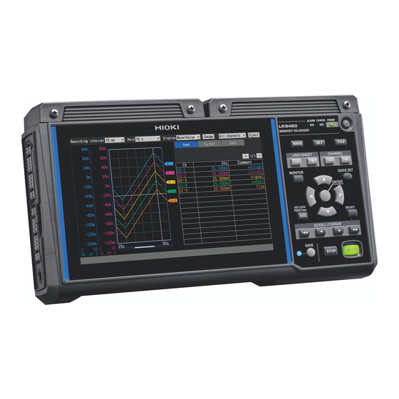
Part Names and Functions; Screens 1.2 Part Names and Functions; Screens LR8450/LR8450-01 Memory HiLogger Front Name Functionality Display The instrument features a 7-inch TFT color LCD. – Connector covers Inside each cover are connectors for plug-in modules. Affix the covers when not installing plug-in modules. - Page 28 Saves the data. The LED next to the key will p. 8 1 turn blue while data is being saved. START Starts measurement. The key will turn green while measurement is in progress. p. 7 9 STOP Stops measurement. HIOKI LR8450A963-02...
- Page 29 – Communicate this number when you contact your authorized Hioki distributor or reseller. This label also indicates whether the instrument is an LR8450 or an LR8450-01. MAC address Indicates the MAC address assigned to your instrument. Do not –...
- Page 30 19, 20, 32, 33 I/O 1 to I/O 4 p. 6 5 1, 4, 9, 14,17, 18, 21, 26, – 31, 34 (Reserved) 15, 16 SYNC.IN, SYNC.OUT – See “8 External Control (Ext. I/O)” in the Instruction Manual. HIOKI LR8450A963-02...
- Page 31 A voltage of 12 V DC is being output from the voltage output terminals. A voltage of 24 V DC is being output from the voltage output terminals. Scaling Scaling is enabled for one or more channels. Instruction Manual HIOKI LR8450A963-02...
- Page 32 Running on battery power. The battery starts to run out. Connect the AC p. 4 0 Adapter to charge the battery. Running on battery power. The battery has run out. Immediately connect the AC adapter to charge the battery. HIOKI LR8450A963-02...
- Page 33 The icon on the right indicates the status of the Battery Pack on the right when the instrument is viewed from the front (looking at the LCD screen), while the icon on the left indicates the status of the Battery Pack on the left. HIOKI LR8450A963-02...
-
Page 34: Plug-In Modules
Communicate this number when you contact your authorized Hioki distributor or reseller. The LR8534 Wireless Strain Unit has the DIP switch, used to select the wiring method. See “Connecting a strain gage or converter” (p. 5 8). -
Page 35: Wireless Modules
RESET Resets the wireless module’s communications settings. p. 7 3 AUTO Automatically configures communications settings between the LR8450-01 and the wireless modules. Input terminals Provides input terminals for each channel. The numerics represent the channel p. 4 9 numbers. - Page 36 Do not – remove this sticker as the number is important. Communicate this number when you contact your authorized Hioki distributor or reseller. Terminal block cover Terminal block covers open toward the LEDs. HIOKI LR8450A963-02...
-
Page 37: Options
There are a total of 10 measurement modules, including 5 plug-in modules and 5 wireless modules. For detailed specifications, see “10 Specifications” in the Instruction Manual. Plug-in modules Plug-in modules can be used with either the LR8450 or the LR8450-01. Number of Maximum... -
Page 38: Other Options
Other options Z1014 AC Adapter (LR8450/LR8450-01 accessory) Z1008 AC Adapter (wireless module accessory) The LR8450/LR8450-01 ships with the Z1014 AC Adapter. Wireless modules ship with the Z1008 AC Adapter. These adapters allow the LR8450/LR8450-01 and wireless modules to be powered by commercial power. (AC power) •... - Page 39 Card (8 GB), Z4006 USB Drive (16 GB) You can save measurement data and settings to an SD Memory Card or USB Drive. Proper operation of the instrument with SD memory cards and USB drives other than options provided by Hioki is not guaranteed. HIOKI LR8450A963-02...
-
Page 40: Measurement Process
See “1.13 Using the A/B Cursors” in the Instruction Manual. Save the data. • You can save measured waveforms and setting conditions onto storage media. See “Saving data” (p. 8 1). • The instrument can load saved waveforms and settings data. See “Loading data” (p. 8 1). HIOKI LR8450A963-02... -
Page 41: Making Connections (Preparing For Measurement)
Connecting voltage output..............p. 6 3 Connecting external control signals ............p. 6 5 2.6 Turning the Instrument On and Off ........p. 6 6 2.7 SD Memory Card and USB Drive.........p. 6 8 2.8 Preparing the Wireless Modules .........p. 7 2 HIOKI LR8450A963-02... -
Page 42: Connecting Plug-In Modules
Connecting Plug-in Modules 2.1 Connecting Plug-in Modules You can connect up to four optional plug-in modules to one LR8450/LR8450-01. Connect modules according to the number of channels necessary for measurement. WARNING Do not remove the connector cover when not connecting plug-in „... - Page 43 You can additionally connect another plug-in module to the module attached to the instrument. Connect another module to the attached module in the same way as to the instrument. IMPORTANT Plug-in modules ship with two spare screws (M3×35 mm). Exercise care not to lose them. HIOKI LR8450A963-02...
-
Page 44: Installing A Battery Pack
Do not solder a wire or other conductor directly to the Battery Pack. „ Do not connect the Battery Pack to any device not specified by Hioki. „ Do not use any Battery Pack that exhibits exterior damage or whose „... - Page 45 Use of other batteries may damage the instrument or cause the Battery Pack to leak liquid, overheat, give off smoke, rupture, or ignite, resulting in serious bodily injury. Hioki is not liable for any equipment damage or accident resulting from use of a battery pack other than the Z1007.
- Page 46 • For reasons related to Battery Pack characteristics, the indicated remaining battery life may diverge from the actual remaining battery life due to factors such as settings during use, operating temperature, and the number of battery charge/discharge cycles. HIOKI LR8450A963-02...
- Page 47 Insert the Battery Pack so that its terminals are aligned with the pins on the wireless module. Insert the Battery Pack and slide it into place. Reattach the cover and tighten the screw. HIOKI LR8450A963-02...
- Page 48 Charging will stop once the Battery Pack is fully charged, and the CHARGE LED will turn off. Rough charge time (LR8450/LR8450-01, wireless modules) • Approx. 7 h (when charging a Battery Pack with little remaining battery life) Continuous operating time on Battery Pack power...
- Page 49 If the Battery Pack starts to run out while the wireless module is working on Battery Pack power, the battery (BATT) LED that remains on will start blinking. Rough continuous operating time after the battery LED starts blinking (reference value) • Approx. 30 min. (at an ambient temperature of 23°C) HIOKI LR8450A963-02...
-
Page 50: Connecting The Ac Adapter
Failure to do so could damage the instrument. When unplugging the power cord from the outlet or the instrument, pull on the „ plug (not the cord). Failure to do so could cause a wire break in the power cord. HIOKI LR8450A963-02... - Page 51 To keep the plug from being pulled out inadvertently, insert the AC Adapter’s output cord into the cable guide on the bottom of the wireless module. Insert the plug on the power cord into an outlet. HIOKI LR8450A963-02...
-
Page 52: Connecting The External Power Supply
2.4 Connecting the External Power Supply The instrument and wireless modules are capable of externally-DC-powered operation. Hioki offers the DC power cord, which connects the instrument and an external power supply with each other. Contact your authorized Hioki distributor or reseller. -
Page 53: Connecting The Cables
Inspect the instrument and wireless module before turning them on to check for damage during storage or shipping. If you find any damage, contact your authorized Hioki distributor or reseller. Inspection of peripheral equipment Do the measurement cables you’re about to connect have tears in their insulation, or is any metal exposed? If you find any damage, do not use the measurement cable. - Page 54 Failure to do so could cause electric shock or damage to the instrument. When using wires with crimp terminals, use insulated terminals designed for use with M3 screws in the following sizes: 6 mm or less 6 mm or less HIOKI LR8450A963-02...
- Page 55 The external control terminals share the ground with the instrument: the grounds of them are not insulated from one another. When using twisted-pair wiring for measurement cables, exercise care not to make contact with adjacent measurement cables or terminals. HIOKI LR8450A963-02...
-
Page 56: Connecting Voltage Cables And Thermocouples
Ω When measuring an instrumentation device (inputting a 4-20 mA current), connect a 250 shunt resistor as shown in the figure. For more information about measuring instrumentation devices, see “Measuring voltage” in the Instruction Manual. Shunt resistor Ω HIOKI LR8450A963-02... - Page 57 Remove the flat-head screwdriver from the button. The cable will be locked in place. Pull gently on the cable and verify that it does not come out. Connect the cable to the measurement target. Close the terminal block cover. HIOKI LR8450A963-02...
-
Page 58: Connecting Resistance Temperature Detectors
Remove the flat-head screwdriver from the button. The cable will be locked in place. Pull gently on the cable and verify that it does not come out. Connect the cable to the measurement target. Close the terminal block cover. HIOKI LR8450A963-02... -
Page 59: Connecting The Humidity Sensor
Connect the yellow cable to the positive terminal and the green cable to the negative terminal. Yellow Yellow (positive) (positive) Green Green (negative) (negative) Pull gently on the cable and verify that it does not come out. Affix the Z2000 to the measurement target. Close the terminal block cover. HIOKI LR8450A963-02... - Page 60 • Changes in humidity (to high humidity from low humidity or to low humidity from high humidity) will affect measured values due to hysteresis. The Z2000 Humidity Sensor’s measured values are affected within a range of about 3% RH. HIOKI LR8450A963-02...
-
Page 61: Connecting A Resistor
Other side of the resistor: Insert the wires into the negative terminal (black) and the SoL terminal (black). Remove the flat-head screwdriver from the button. The cable will be locked in place. Pull gently on the cable and verify that it does not come out. Close the terminal block cover. HIOKI LR8450A963-02... -
Page 62: Connecting A Strain Gage Or Converter
Affixing connection confirmation labels Affix the included connection confirmation labels as desired (for example, on the back of the terminal block cover). Connection confirmation label If label is affixed to the terminal block cover HIOKI LR8450A963-02... - Page 63 How to display the strain gage connection guide Press the QUICK SET key, and choose [Strain gauge connection guide]. The strain gage connection diagrams will be displayed. See “1.15 Configuration Navigator (Quick Set)” in the Instruction Manual. HIOKI LR8450A963-02...
- Page 64 • After installing the strain gage and completing its wiring, perform auto-balancing before measurement. See “Measuring strain” in the Instruction Manual. • Secure the strain gage wires in place and ensure that the gage itself is not subjected to force. HIOKI LR8450A963-02...
-
Page 65: Connecting Pulse Input
Example connecting to pulse 4 and GND How to check the pin assignments of the external control terminals Press the QUICK SET key, and choose [External connection guide]. Names of the external control terminals will be displayed. HIOKI LR8450A963-02... -
Page 66: Connecting Alarm Output
Example connecting to alarm output 4 and GND How to check the pin assignments of the external control terminals Press the QUICK SET key, and choose [External connection guide]. Names of the external control terminals will be displayed. HIOKI LR8450A963-02... -
Page 67: Connecting Voltage Output
Do not apply a voltage from an external source to the voltage output terminals. „ Doing so could damage the instrument. Connect cables to voltage output terminals before turning on output. „ Connecting cables to voltage output terminals while voltage is being output could damage the instrument. HIOKI LR8450A963-02... - Page 68 Example connecting to voltage output 2 and GND How to check the pin assignments of the external control terminals Press the QUICK SET key, and choose [External connection guide]. Names of the external control terminals will be displayed. HIOKI LR8450A963-02...
-
Page 69: Connecting External Control Signals
Example connecting to external input 2 and GND How to check the pin assignments of the external control terminals Press the QUICK SET key, and choose [External connection guide]. Names of the external control terminals will be displayed. HIOKI LR8450A963-02... -
Page 70: Turning The Instrument On And Off
In addition, you can continue measurement even in the event of an outage by using the Z1007 Battery Pack. See “2.2 Installing a Battery Pack” (p. 4 0). LR8450/LR8450-01 (1) Turning on the instrument Press the power key to turn on the instrument. The POWER LED will turn green. - Page 71 • The BATT LED will be turned off. CHARGE • While the battery charging is in progress, the LED remains on. Charging battery The instrument can charge the Battery Pack even during the power-off condition. HIOKI LR8450A963-02...
-
Page 72: Sd Memory Card And Usb Drive
You can also load previously saved data into the instrument to reproduce it. See “3 Saving and Loading Data” in the Instruction Manual. Use the following Hioki options for saving data. Z4001 SD Memory Card (2 GB), Z4003 SD Memory Card (8 GB), Z4006 USB Drive (16 GB) - Page 73 • Hioki is not liable for data stored on SD Memory Cards and USB Drives, regardless of the nature or cause of the accident or damage involved. Data saved on SD Memory Cards and USB Drives may become unreadable after an extended period of time has passed.
-
Page 74: Inserting And Removing Sd Memory Cards
After the message [SD card can be safely removed] has been displayed, you can remove the SD Memory Card. Push in on the SD Memory Card. Once the card is sticking out slightly, grip it and pull it out. HIOKI LR8450A963-02... -
Page 75: Inserting And Removing Usb Drives
• You can replace an SD Memory Card or USB Drive while real-time saving is enabled. See “3.3 Saving Data” in the Instruction Manual. • If an FTP client connects to the instrument, ejecting media will cause a failure. Close the FTP client connection before conducting the procedure for ejecting the media again. HIOKI LR8450A963-02... -
Page 76: Preparing The Wireless Modules
Preparing the Wireless Modules 2.8 Preparing the Wireless Modules The LR8450-01 is capable of communications with not only plug-in modules but also wireless modules. Attach the Z3230 Wireless LAN Adapter to the wireless module before use. The Z3230 comes with each wireless module. -
Page 77: Registering The Wireless Modules
Preparing the Wireless Modules Registering the wireless modules You can register up to seven wireless modules in the LR8450-01. It is recommended to follow the instructions of the configuration navigator when you register the modules for the first time. Registering the wireless modules with the configuration navigator Following the instructions from the registration guide, you can register the wireless modules. -
Page 78: Mounting The Instrument On A Wall Or Other Surface
No mounting screws come with the wireless module. Please use commercially available screws. Recommended screws: M4×8 mm or longer Wireless module M4 screws Mounting plate ×2 M3 flat-head screws ×2 Rear Front Dimensions of the mounting plate 75 mm 2-R2.2 50 mm HIOKI LR8450A963-02... -
Page 79: Settings And Operation
Formatting storage media ..............p. 8 0 Saving data .................... p. 8 1 Loading data................... p. 8 1 Initialization (resetting the system) ............p. 8 2 Key lock (disabling keys) ................ p. 8 2 3.2 Setting Example (Measuring Temperature Using Thermocouples) ....p. 8 3 HIOKI LR8450A963-02... -
Page 80: Basic Operation
[Measure] main tab, you can switch the screen’s contents among the following five sub tabs: Auto save [Record], [Auto save], [Manual save], [Display], and [Settings]. Manual save Display Main tabs Settings Sub tabs Return to [Record]. Focus Meas_1.png HIOKI LR8450A963-02... -
Page 81: Configuration Process
See “1.3 Setting Measurement Conditions” in the Instruction Manual. Configure the input channels. Press the key to display the [Channel] settings screen. Set the input type, such as voltage and temperature, and the range. See “1.4 Configuring Input Channels” in the Instruction Manual. HIOKI LR8450A963-02... -
Page 82: Changing And Accepting Settings
The setting will be accepted. Pressing the key will cancel the settings. You can also change the channel being configured with the following keys: UNIT/SHEET • keys: Changes the measurement module number. • CHANNEL keys: Changes the channel number. HIOKI LR8450A963-02... -
Page 83: Starting And Stopping Measurement
Auto save (real-time save) The instrument can save waveform data (using the real-time save function) to an SD Memory Card or a USB Drive while measurement is in progress. See “3 Saving and Loading Data” in the Instruction Manual. HIOKI LR8450A963-02... -
Page 84: Formatting Storage Media
• When you format an SD Memory Card or USB Drive, all the saved data will be erased. Be sure to back up any important data. HIOKI LR8450A963-02... -
Page 85: Saving Data
Up Arrow Down Arrow keys to select folders. Right When you press the Arrow key, the screen will move into the folder. When you press the Left Arrow key, the screen will move back to the previous folder. HIOKI LR8450A963-02... -
Page 86: Initialization (Resetting The System)
Pressing a key will cause a message informing the user that the key lock is engaged to be displayed on the screen. You can disable the key lock by pressing and holding the key again for at least 3 seconds. With the key lock engaged When attempting key operation with the key lock engaged HIOKI LR8450A963-02... -
Page 87: Setting Example
This section describes how to configure the settings to measure temperature with the instrument and a plug-in module You can measure temperature with the following products. • Logger: LR8450 or LR8450-01 • Plug-in module: U8550 Voltage/Temp Unit • Thermocouple: Type K Preparing for measurement Insert storage media. -
Page 88: Thermocouples)
Switching over to the [Unit 1] sub tab allows you to configure the settings for 15 channels at once. Clear the check boxes of channels U1-2 to U1-15, exempting the channels from the measurement subjects. Check box Main tab Sub tab HIOKI LR8450A963-02... - Page 89 See “1.14 X-Y ” in the Instruction Manual. Compositing Stop measurement. START Press the key. The confirmation window [Stop measurement?] will appear. Choose [Yes], and then press the ENTER key to stop measurement. Save the measured waveform data. HIOKI LR8450A963-02...
- Page 90 Press the ENTER key while [Save] is selected. The instrument can load binary-form (LR8450-specific-form) waveform data only. When you do not name files, the instrument will automatically name them. Load the saved waveform data. When you press the FILE key, the file list will appear.
-
Page 91: Specifications
Specifications For detailed information on the instrument’s specifications, see “10 Specifications” in the LR8450/ LR8450-01 Instruction Manual stored on the accompanying CD. 4.1 Memory HiLogger Basic Specifications Operating Indoors, Pollution Degree 2, altitude up to 2000 m (6562 ft.) environment Operating −10°C to 50°C (14°F to 122°F), 80% RH or less (non-condensing) -
Page 92: Plug-In Module Specifications
Maximum rated 300 V AC, DC (Measurement Category II) terminal-to-ground Between any input channel (SoH, SoL, +, −) and the instrument (LR8450/LR8450-01) or voltage between any two modules Anticipated transient overvoltage: 2500 V... -
Page 93: U8552 Voltage/Temp Unit
±0.5 V DC voltage Maximum channel-to- Non-isolated (all channels share common GND) channel voltage Maximum rated 30 V rms AC or 60 V DC (between analog input channels and the instrument [LR8450/ terminal-to-ground LR8450-01]) voltage Anticipated transient overvoltage: 330 V HIOKI LR8450A963-02... -
Page 94: Lr8530 Wireless Voltage/Temp Unit
(Charging temperature range: 5°C to 35°C) humidity range Storage temperature −20°C to 60°C (−4°F to 140°F), 80% RH or less (non-condensing) and humidity range Maximum input ±100 V DC voltage Maximum channel-to- 300 V DC channel voltage HIOKI LR8450A963-02... -
Page 95: Lr8533 Wireless High Speed Voltage Unit
±0.5 V DC voltage Maximum channel-to- Non-isolated (all channels share common GND) channel voltage Maximum rated 30 V rms AC or 60 V DC (between each analog input channel and the enclosure) terminal-to-ground Anticipated transient overvoltage: 330 V voltage HIOKI LR8450A963-02... -
Page 96: Wireless Lan Adapter Specifications
Indoors, Pollution Degree 2, altitude up to 2000 m (6562 ft.) environment Operating −20°C to 55°C (−4°F to 131°F), 80% RH or less (non-condensing) temperature and humidity range Storage temperature −20°C to 60°C (−4°F to 140°F), 80% RH or less (non-condensing) and humidity range HIOKI LR8450A963-02... -
Page 97: Maintenance And Service
Regular calibration is necessary in order to obtain correct measurement results at the defined accuracy. The calibration interval depends on factors such as operating conditions and environment. Please determine the appropriate calibration interval based on your operating conditions and environment and have Hioki calibrate it accordingly on a regular basis. HIOKI LR8450A963-02... - Page 98 When sending the instrument to be repaired, attach a description of the issue. Hioki is unable to guarantee that instruments will not be damaged during shipment. When transporting the Z1007 Battery Pack on an aircraft •...
-
Page 99: Troubleshooting
This section describes what to check when you have a problem and suggests possible solutions. Before sending the instrument to be repaired If you believe your instrument might be damaged or malfunctioning, check the following information before contacting your authorized Hioki distributor or reseller. Symptom Check items... - Page 100 Troubleshooting Symptom Check items Solutions I can’t save data • Is Hioki optional media being used? Use a Hioki optional SD Memory Card or to storage media USB Drive. (SD Memory Proper operation of the instrument with Card, USB Drive).
-
Page 101: Error Messages
Use a computer to delete or rename folders. ERR_FL08 Confirm the A-B cursor position The A/B cursors are inappropriately placed (for example, outside the waveform range). Check the positions of the A/B cursors. HIOKI LR8450A963-02... - Page 102 See “8.1 Configuring Voltage Output (VOUTPUT)” in the Instruction Manual. WARN_SY05 No channel selected for measurement. The measurement preferences of all channels are set to Off. Set one or more of them to On before starting measurement. HIOKI LR8450A963-02...
- Page 103 WARN_FL09 Unsaved data present. An SD Memory Card or a USB Drive is not inserted. Alternatively, available space may start to run out. Insert an SD Memory Card or a USB Drive, and then manually save necessary data. HIOKI LR8450A963-02...
- Page 104 Enter the [SSID] for the access point in the wireless LAN settings. See “9.4 Using the Wireless Modules (LR8450-01 only)” in the Instruction Manual. WARN_SU02 Select a channel to execute auto balance. Choose channels for which you want to execute auto-balance.
- Page 105 When communicating data through the at least 8 characters. wireless LAN after encryption, set a password with at least eight characters. See “9.4 Using the Wireless Modules (LR8450-01 only)” in the Instruction Manual. WARN_WLAN08 Invalid IP address has been entered. Check the following points: •...
- Page 106 Settings for external I/O3 modified to [External input 3] terminal was set to [Trigger input] external trigger because the external trigger was set to [ON]. Check if the settings are appropriate. See “2.5 Applying Triggers Based on External Sources” in the Instruction Manual. HIOKI LR8450A963-02...
- Page 107 – Failed to eject SD card. Any attempts to eject the SD Memory Card in the middle of internal processing may fail. Wait for a while or cycle the instrument. After that, eject it. HIOKI LR8450A963-02...
- Page 108 Measurement cannot be turned on. Set the [Recording interval] [2 ms] recording interval to [2 ms] or more. longer. – The recording interval cannot be set to Reduce the number of channels. [1 ms] because the number of measurement channels exceeds 151. HIOKI LR8450A963-02...
-
Page 109: Led Indicators (Wireless Modules)
Emits 5 flashes for 1 s. Preparing. Wireless communications status CONNECT Status Remedy No communications in progress. – Lighting up. Communicating with LR8450-01. – Flashes in 2 s interval. Communications disrupted. Please wait. Reconnecting. Flashes in 1 s interval. Connecting with auto-connect. Please wait. -
Page 110: Disposing Of The Instrument
Turn over the instrument and remove the six screws shown in the figure. Remove the lower case. Pull up on the lithium battery on the printed circuit board and cut the positive and electrode leads with the plier. Lithium battery HIOKI LR8450A963-02... -
Page 111: Faq
When using wireless units, there will The difference will be about 20 ms with robust “1.16 Measurement appear to be differences in sampling wireless communications and more when the Data” in the timing between units. networking signal is weak. Instruction Manual HIOKI LR8450A963-02... - Page 112 ±1.0°C. Saving data Question Answer Can I use any commercially available Use only Hioki optional SD Memory Cards or USB “2.7 SD Memory SD memory card or USB drive? Drives. Proper operation is not guaranteed when Card and USB Drive”...
- Page 113 “.MEM”: Binary waveform data that can be loaded “3.1 Data That “.MEM” and “.LUW” extensions? by the instrument or the Logger Utility Can Be Saved “.LUW”: Logger Utility waveform data that cannot and Loaded” in the be loaded by the instrument Instruction Manual HIOKI LR8450A963-02...
-
Page 114: Open-Source Software
You have the right to obtain, modify, and redistribute the source code of the software under these licenses. For details, visit the following website. https://www.hioki.com/en/support/oss Hioki would prefer you not to direct any inquiries on the content of the source code. HIOKI LR8450A963-02... -
Page 115: Index
DC power cord............48 DIP switches ............. 60 Disposal ..............106 MAC address ............25 Main tabs ..............76 Maintenance ............. 93 MEASURE LED ..........31 ERR LED ............31 Measurement Error messages ............97 Start and stop ............79 HIOKI LR8450A963-02... - Page 116 SD Memory Cards ..........35 Z2000 ..............34 Serial number ..........25 Z3230 ..............34 Service life ..............93 Z5040 ..............17 Setting example ............83 ......Zero adjustment Instruction Manual Settings and operation..........75 Specifications ......87 Instruction Manual HIOKI LR8450A963-02...
- Page 117 HIOKI LR8450A963-02...
- Page 118 HIOKI LR8450A963-02...
- Page 119 HIOKI LR8450A963-02...
- Page 120 HIOKI LR8450A963-02...
Need help?
Do you have a question about the LR8450 and is the answer not in the manual?
Questions and answers