Dräger Infinity Delta Instructions For Use Manual
Infinity delta series patient monitoring device
Hide thumbs
Also See for Infinity Delta:
- Quick reference manual (31 pages) ,
- Quick reference manual (34 pages)
Table of Contents
Advertisement
Quick Links
Advertisement
Chapters
Table of Contents

Related Manuals for Dräger Infinity Delta


Summary of Contents for Dräger Infinity Delta
-
Page 1: Instructions For Use
Instructions for Use Infinity Delta Series Infinity Patient Monitoring Series WARNING Software VF8 To properly use this medical device, the user must obtain a full understanding of the performance characteristics of this medical device prior to use by carefully reading these Instructions for Use. - Page 2 Draeger Medical Systems, Inc. Covidien 3135 Quarry Road 15 Hampshire St. Telford, PA 18969-1042 Mansfield, MA 02048 Infinity Delta Series Instructions for Use Authorized EC representative: Software VF8 Covidien Ireland Limited ©Draeger Medical Systems, Inc.2010. IDA Business & technology Park All rights reserved.
-
Page 3: Table Of Contents
Overview Intended Use ........................4 Indications for Use ......................4 Intended Patient Categories ....................5 Documentation Features....................5 Warnings, Cautions, Notes ..................5 Cross-references......................5 Quick Reference Tables ....................5 Footer ..........................5 Applicability ........................6 Safety Considerations......................6 Site of Operation ......................7 Inspection and Maintenance ..................8 Defibrillator Precautions ..................10 Pacemakers ......................11 Peripheral Devices ....................11 Electrosurgery ......................11... -
Page 4: Intended Use
ERIES UIDE Intended Use The Infinity Delta Series (Delta/Delta XL/Kappa) Monitors are intended for multi- parameter patient monitoring. The devices will produce visual and audible alarms if any of the physiological parameters monitored vary beyond preset limits and timed or alarm recordings will be produced. -
Page 5: Intended Patient Categories
Intended Patient Categories The Infinity Delta Series (Delta/Delta XL/Kappa) monitors are intended to be used on adult, pediatric, and neonatal populations, with the exception of the parameter Cardiac Output, ST Segment Analysis, and arrhythmia which are intended for use in the adult and pediatric populations only;... -
Page 6: Footer
Model-specific information is documented as required. NOTE: Software funtionality is identical between the following products: Infinity Delta = Siemens SC 7000 Infinity Delta XL = Siemens SC 9000XL Infinity Kappa = Siemens SC 8000 with the following exceptions as noted: Alarm bar (see pages 1-5, 2-16, and 3-17). -
Page 7: Site Of Operation
’ NFINITY ELTA ERIES UIDE Site of Operation Only use these devices in areas that meet the environmental requirements outlined in the technical data section. WA R N I N G : D o n o t o p e r a t e t h e d e v i c e i n a r e a s s u c h a s : m a g n e t i c r e s o n a n c e i m a g i n g ( M R I ) e nv i r o n m e n ts , a i r c r a ft , a mb u l a n c e , h o m e o r h y p e rb a ri c c h a mb e r s . -
Page 8: Inspection And Maintenance
’ NFINITY ELTA ERIES UIDE CAUTION: To avoid short-circuiting and otherwise damaging the device, do not allow fluids to come in contact with the device. If fluids are accidentally spilled on the equipment, remove the affected unit from service as soon as possible and contact the technical personnel to verify that patient safety is not compromised. - Page 9 ’ NFINITY ELTA ERIES UIDE WA R N I N G : R e pa i r o f t h e d e v i c e m a y o n l y b e c a r ri e d o u t b y t r a i n e d s e r v i c e p e r s o n n e l o t h e r w i s e t h e c o r r e c t f u n c t i o n i n g o f t h e d e v i c e m a y b e c o m p r o m i s e d .
- Page 10 ’ NFINITY ELTA ERIES UIDE Dräger recommends that: Maintenance, modifications, and repairs are carried out by trained personnel. Components are replaced with Dräger provided spare parts, otherwise the correct functioning of the device may be compromised. Devices are used in accordance with Dräger Instructions for Use. General Electrical Safety WA R N I N G : To p r o t e c t t h e pa t i e n t f r o m p o s s i b l e i n j u r y d ue t o...
-
Page 11: Defibrillator Precautions
’ NFINITY ELTA ERIES UIDE Defibrillator Precautions The monitor and peripheral devices are protected against high-frequency interference from defibrillators and electrosurgical units and against 50- and 60-Hz power line interference. Following defibrillation, the monitor begins displaying waveform data again within 10 seconds if the correct electrodes are used and those electrodes are applied in accordance with the manufacturer’s instructions. - Page 12 ’ NFINITY ELTA ERIES UIDE WA R N I N G : T he N e o M e d a n d M u l t i M e d 1 2 p o d s a r e n o t i n t e n d e d f o r u s e d u r i n g e l e c t r o s ur g e r y.
-
Page 13: Electromagnetic Compatibility
’ NFINITY ELTA ERIES UIDE Electromagnetic Compatibility The monitor has been designed and tested for compliance with current regulatory standards (IEC 60601-1-2 and CISPR 11 Class B) regarding its capacity to reduce electromagnetic emissions (EMI) and to block EMI from external sources. Dräger recommends these procedures to reduce electromagnetic interference: Use only Dräger provided accessories, otherwise the correct functioning of the device may be compromised (see appendix C). - Page 14 ’ NFINITY ELTA ERIES UIDE Table of Contents Overview Intended Use ........................4 Indications for Use ......................4 Intended Patient Categories ................... 5 Documentation Features ....................5 Safety Considerations ..................... 6 Electromagnetic Compatibility ..................13 Table of Contents ......................14 Introduction Overview ........................1-2 Power Sources (Delta/Delta XL) ................1-13...
- Page 15 ’ NFINITY ELTA ERIES UIDE Admitting a Patient .......................4-2 Transferring Patient Data .....................4-3 Discharging a Patient ....................4-7 Alarms Overview.........................5-2 Alarm Priorities......................5-3 Alarm Latching ......................5-5 Alarm Management .......................5-5 Alarm Setup (Alarm Limits Table)................5-6 Alarm History Table.....................5-14 OR Alarms ........................5-15 Trends Overview ........................6-2 Trend Setup ........................6-2 Trend Graphs ........................6-3 Trend Table ........................6-6...
- Page 16 ’ NFINITY ELTA ERIES UIDE About the Arrhythmia Template ..................9-3 Arrhythmia Setup ......................9-5 Status Messages ......................9-9 ST Monitoring Overview ........................10-2 MultiMed Pods for ST Analysis .................10-3 ST Display ........................10-4 ST Analysis Setup ......................10-4 ST Alarms Table .......................10-10 Status Messages .....................10-11 EEG Monitoring Overview ........................11-2 Precautions .........................11-2...
- Page 17 ’ NFINITY ELTA ERIES UIDE Pulmonary Wedge Pressure Display ..............14-18 Status Messages ......................14-20 Cardiac Output (C.O.) Overview ........................15-2 Accuracy ........................15-3 Main Screen Display ....................15-4 C.O. Setup - Hardware ....................15-5 C.O. Measurement Procedures ................15-10 Averaging C.O. Measurements ................15-12 Status Messages ......................15-14 Calculations Overview ........................16-2 Physiological Calculations (Hemo/Oxy/Vent Calculations) ........16-3...
- Page 18 ’ NFINITY ELTA ERIES UIDE Sampling Methods ......................19-6 Display Features ......................19-9 etCO2 Setup ......................19-11 Cleaning, Calibration and Verification ..............19-14 Status Messages ......................19-16 Microstream® etCO2 Monitoring Overview ........................20-2 Precautions .........................20-2 Connection ........................20-3 etCO2 Display Features .....................20-4 etCO2 Setup ........................20-6 Calibration ........................20-7 Status Messages ......................20-8 Respiratory Mechanics Overview ........................21-2...
- Page 19 ’ NFINITY ELTA ERIES UIDE Neuromuscular Transmission (NMT) monitoring Overview ........................24-2 Precautions .........................24-3 Connections ........................24-4 Monitoring Modes .......................24-5 Taking NMT Measurements ..................24-6 Status Messages ......................24-9 Bispectral Index (BISx) monitoring Overview ........................25-2 Precautions .........................25-2 Patient Preparation .....................25-3 Display Features ......................25-3 BIS Setup ........................25-5 Checking the Impedance ...................25-8 Status Messages ......................25-9 Pulse Contour Cardiac Output (PiCCO) monitoring...
- Page 20 ’ NFINITY ELTA ERIES UIDE SvO2/CCO Monitors ....................28-17 Radiometer MicroGas 7650 Monitor ..............28-19 Aspect A-2000 BIS“ Monitor ..................28-19 Independent Surgical Display (ISD) ................28-20 MIB Status Messages ....................28-23 Dräger Infant Incubator C2000/C2000e ..............28-24 Dräger Infant Incubator Caleo .................28-27 Dräger Babytherm Infant Warmer ................28-30 Somanetics INVOS Cerebral/Somatic Oximeter 5100C ........28-33 Cleaning and Disinfecting Overview ........................29-2...
- Page 21 ’ NFINITY ELTA ERIES UIDE Pulse Contour Cardiac Output (PiCCO) ..............C-19 Invasive Blood Pressure (IBP) .................. C-20 Cardiac Output ......................C-23 Transcutaneous Blood Gas..................C-24 End-Tidal CO2 (etCO2)....................C-24 etCO2/Respiratory Mechanics................... C-26 FiO2..........................C-26 MultiGas Monitoring....................C-27 NMT Monitoring ......................C-28 BISx Monitoring ......................
- Page 22 ’ NFINITY ELTA ERIES UIDE This page intentionally left blank XL/K ELTA ELTA APPA...
-
Page 23: Introduction
1 Introduction Overview.........................1-2 Overview (Delta/Delta XL)..................1-2 Overview (Kappa) ....................1-3 System Components .....................1-4 Base Unit........................1-5 Kappa Video Display.....................1-10 Device Markings ....................1-11 Auxiliary Display and Other Components ............1-12 Power Sources (Delta/Delta XL) .................1-13 Infinity Docking Station (IDS)................1-14 Battery Power ......................1-14 Power Sources (Kappa) ....................1-17 Getting Started......................1-19 Accessing the Main Screen..................1-19 Using the Rotary Knob ..................1-20... -
Page 24: Overview
NTRODUCTION Overview The patient monitor is intended for adult, pediatric, and neonatal monitoring. It can be used as a standalone device or can be connected to the Infinity network. Monitor use is restricted to one patient at a time. The following optional software features are available: ACE full arrhythmia (Arrhythmia II) Hemodynamic &... -
Page 25: Overview (Kappa)
VERVIEW Overview (Kappa) The basic Kappa monitoring system consists of two components: a processing CPU base unit and a display unit. These Instructions for Use use the word “Kappa” monitor to refer to the CPU base unit, unless otherwise specified. The Kappa is designed to operate with a separate large screen display. -
Page 26: System Components
NTRODUCTION System Components NOTE: For a complete list of accessories available with this product, see Appendix C. The monitor configuration may vary. Refer to your hospital’s technical personnel for more information. The parts below include standard and optional components. The Delta or Delta XL requires: Monitor Power supply Country specific power cord and monitor... -
Page 27: Base Unit
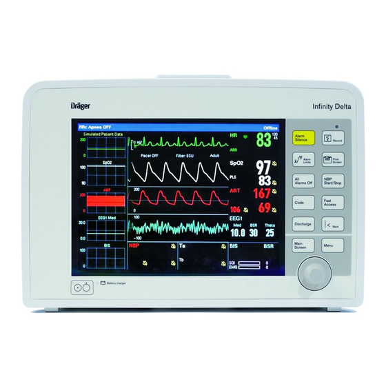
VERVIEW Delta, Delta XL and Kappa: Delta/Delta XL MIB II 1 to 4 option for IDS/ Kappa - advance communication 6 to 8 channel option 3-Lead ST analysis option Wireless networking option ARIES option Physio calculations option ACE full arrhythmia option ARIES/Physio Calcs/ACE arrhythmia option package OR mode option (loaded in the monitor) Base Unit... - Page 28 NTRODUCTION Monitor Front View – Delta XL Fixed keys Main menu fixed key Main screen fixed key Battery charge indicator Power switch Monitor Front View – Kappa Fixed keys HemoMed connector Rotary knob Connectors for Aux/Hemo or PodCom Analog (balloon pump)/sync MultiMed connector (QRS sync defib) connector NBP hose connector...
- Page 29 VERVIEW Monitor Rear View – Delta External (lead-acid) battery compartment Connector for docking station/ interface plate Connector for AC adaptor Slot for etCO module Monitor Rear View – Delta XL External (lead-acid) battery compartment Connector for docking station/ interface plate Connector for AC adapter Slot for etCO module...
- Page 30 NTRODUCTION Monitor Rear View – Kappa Analog out / Sync (balloon pump/ QRS Sync (for example, for defibrillator defibrillator) (X10) connection) Alarm output (nurse call) , export PCMCIA slot (“Memory card”) protocol (X5) Recorder output (X13) Infinity network connector (X14) Video out (VGA) (X16) Potential equalization RS232 connector, Scio module, Smart...
- Page 31 VERVIEW Monitor Left Side – Delta XL HemoMed connector Connectors for Aux/Hemo or PodCom MultiMed connector NBP connector Monitor Left Side – Kappa Advanced Communications Options CANBUS connector for old Scio module (PN 68 71 255) MIB connectors Scio/Independent Surgical Display (ISD) connector XL/K ELTA...
- Page 32 NTRODUCTION Monitor Right Side – Delta/Delta XL PCMCIA slot: memory card Infinity network connector QRS sync RS232 connector, Scio module, Smart Pod, remote keypad, Vital Connect Cable (VCC), Alarm output (nurse call) – (X8) Analog out (X10) NOTE: Alarm output (nurse call) requires the alarm output cable with partnumber 4314626.
-
Page 33: Kappa Video Display
VERVIEW Kappa Video Display The Kappa complies with the requirements of IEC 60601-1 when used with Dräger approved medical grade displays, available in multiple screen sizes (see page B-18.) CAUTION: The remote display output on the IDS is not galvanically isolated. If you use a video monitor other than one specified by Dräger, it must comply with IEC 60601-1 and be suitable for use in the presence of flammable anesthetic mixtures and/or flammable liquids (see “Safety Considerations”... -
Page 34: Device Markings
NTRODUCTION Device Markings The following table describes symbols that appear on the monitor and its accessories that were not described on pages 1-5 through 1-10: Monitor on/off Remote keypad in Battery-operated RS 232 equipment Attention! Consult the Analog out accompanying document Defibrillator-proof equipment, Analog out Type CF... -
Page 35: Auxiliary Display And Other Components
VERVIEW China RoHS marking Video display output Contains lead - Recycle properly Auxiliary Display and Other Components The following devices enable remote viewing of patient data. Remote Display – Allows you to view but not control monitor functions away from the bedside. Dräger strongly recommends that you use only approved video monitors, otherwise the function of the monitor may be compromised. -
Page 36: Power Sources (Delta/Delta Xl)
NTRODUCTION MIB protocol converters – The monitor can display numeric, waveform, and trended data generated by external monitoring devices. Dräger provides protocol converters that translate the output from external devices into the Medical Information Bus (MIB) protocol, using the appropriate 1073 standards (IEEE 1073.3.2 or 1073.3.1 and 1073.4.1). -
Page 37: Infinity Docking Station (Ids)
OWER OURCES ELTA ELTA Infinity Docking Station (IDS) The Infinity Docking Station (IDS) helps facilitate patient transport, allowing you to remove the monitor from the bedside and dock it at another station while maintaining patient and monitor connections. This feature, called Pick and Go, is explained in further detail on page 3-5. - Page 38 NTRODUCTION WA R N I N G : Wo r n o u t o r d e f e c t i v e b a t t e r i e s c a n s i g n i f i c a n t l y r e d u c e t h e s e t i m e s .
- Page 39 OWER OURCES ELTA ELTA Battery Charge Display Display Charge Left Action The monitor sounds single attention tone. Internal battery is very low Immediately connect monitor to AC (<25%). adapter, or Infinity Docking Station. Replace external battery. Internal battery is depleted; <5 Immediately connect monitor to AC minutes of power remaining.
-
Page 40: Power Sources (Kappa)
NTRODUCTION Charging the Batteries Before using the Delta/Delta XL monitor for the first time, charge the internal battery for a maximum of 6.5 hours and the external battery for 3.5 hours. NOTE: For the SC 7000/9000XL internal lead-acid battery, charge for a maximum of 4.5 hours the first time. - Page 41 OWER OURCES APPA When the monitor is operating solely on battery power, a message along the top of the screen tells you if the battery charge is low, and a bar graph indicates how much power is left (see the table below.) The battery is automatically recharged whenever you plug the monitor into an AC outlet.
-
Page 42: Getting Started
NTRODUCTION Getting Started To turn the monitor on Press the power key ( O ), located on the bottom left of the Delta or Delta XL monitor's front panel and on the top left of the Kappa monitor’s front panel. The monitor turns on the power indicator light, lights the alarm bar, emits a power-on tone, lights up the screen, performs a self-test, and displays the main screen. -
Page 43: Using The Rotary Knob
ETTING TARTED Parameter boxes show values, alarm limits, and special icons for selected parameters. Parameters and their associated waveforms are color-coded for easy recognition. NOTE: You can access parameter setup menus by scrolling through the parameter boxes using the rotary knob and selecting the parameter you wish to configure. See “Quick Reference –... -
Page 44: Menu Access
NTRODUCTION Remote Keypad NOTE: The remote keypad's C.O. key is not available with the PiCCO pod. The remote keypad has all of the fixed keys that are on the monitor and additional keys that perform the following: — Displays trend graphs Trends —... -
Page 45: Fast Access Menu
CCESS Fast Access Menu The Fast Access menu accesses the following submenus and screens directly: Fast Access Item See page Fast Access Item See page Remote View 3-13 Calculations 16-1 OxyCRG (Neonatal only) 12-9 Show All Leads 8-18 Alarm History 5-14 Lab Data 16-8... -
Page 46: Fixed Keys
NTRODUCTION Fixed Keys Fixed keys on the monitor front panel allow you to perform commonly executed functions. Fixed Key Description Fixed Key Description Alarm Silences the active alarm tone Record Starts/stops a timed Silence for one minute recording. Alarm Limits Opens a table from which you Print Prints the currently displayed... -
Page 47: Data Archive Applications
RCHIVE PPLICATIONS Data Archive Applications The monitor stores events, alarms and trends automatically or at the user’s request, depending on the type of information. Some events are automatically recorded and stored. Others can be stored manually by pressing the fixed key. The monitor Mark automatically stores alarm conditions and arrhythmia events that you have configured for storage in the Alarm Limits table (see page 5-6) and in the Arrhythmia setup table... -
Page 48: Storing Events
NTRODUCTION Storing Events Automatic Storage The monitor stores events automatically, if you have first correctly configured the Alarm Limits and Arrhythmia Setup tables. You can enable individual parameter alarms in the column of the Alarm Alarms Limits and/or the ARR Setup screens. Configure event storage in the column Archive by selecting... -
Page 49: Event Recall
RCHIVE PPLICATIONS Event Recall The monitor stores monitoring data (waveforms and parameter values), alarm conditions, and arrhythmia events on the Event Recall screen. You can view up to 50 stored events, each containing 20 seconds of data, with associated date and time stamps. -
Page 50: Help Functions
NTRODUCTION Navigating the Event Recall Screen To scroll forward and back through 20 seconds of waveform data, click on arrows at either side of scroll bar at the bottom of the screen. To scroll through the list of parameter values at the time of data capture, click on the arrow keys above the list of parameters at the right of the screen: To scroll through the waveforms displayed at the time of data capture, click on the Prev (Previous) and Next control buttons under waveform display. - Page 51 2 Monitor Setup Overview.........................2-2 Configuring the Monitor....................2-2 Main Menu Setup.....................2-2 Quick Reference – Main Menu Setup ..............2-3 Setups Management......................2-9 Specialty Menus......................2-12 OR Mode ........................2-12 Unit Manager ......................2-14 Biomed ........................2-20 Parameter Colors ....................2-22 Software Upgrades ......................2-24...
-
Page 52: Monitor Setup
ONITOR ETUP Overview This chapter describes how to configure the monitor and offers tips on software upgrades. If the monitor is connected to a network, you can save defined setups and restore them for display. Configuring the Monitor Main Menu Setup The Main menu allows you to access submenus, display screens, and execute certain monitor setup functions. -
Page 53: Quick Reference - Main Menu Setup
ONFIGURING THE ONITOR Quick Reference – Main Menu Setup The Main Menu Menu Item Description Available Settings Cursor Tool Provides access to the Cursor Tool • Setup submenu (see below), which allows you • Horizontal Cursor to select three waveforms displayed with •... - Page 54 ONITOR ETUP The Main Menu Menu Item Description Available Settings Vertical Displays a vertical cursor. You can scroll Not applicable Cursor forward and backward across all waveforms. NOTES: • The cursor has no value. • The cursor remains displayed until the window closes.
- Page 55 ONFIGURING THE ONITOR The Main Menu Menu Item Description Available Settings Parameters Accesses the parameters’ setup menus. • Click on one of the listed parameters to access its setup menu: (for example, ECG, ARR, ST, ART, PA CVP, RA, SPO2, NBP, RESP, etCO2, C.O.
- Page 56 ONITOR ETUP The Main Menu Menu Item Description Available Settings Max. Determines the number of waveform • Click on 4, 5, 6, 7, or 8 Channels channels and parameters displayed. NOTE: The number of waveforms depends on the software option you have installed (see page 1-20 for a list of options).
- Page 57 ONFIGURING THE ONITOR The Main Menu Menu Item Description Available Settings MultiGas Displays a combined O /Agent/N To display the MultiGas parameter Parameter parameter box. box: NOTE: You can also display or cancel the • Click on MultiGas Parameter. MultiGas Parameter box from the O •...
- Page 58 ONITOR ETUP The Main Menu Menu Item Description Available Settings Monitor Options submenu Date & Time Sets the date and time displayed in the To set the monitor date and time: lower right potion of the main screen 1) Click on Date & Time. NOTES: 2) Click on Current Date.
-
Page 59: Setups Management
ETUPS ANAGEMENT Setups Management You can save and restore the current patient and monitoring settings. When you discharge a patient, the monitor automatically saves the default settings, while both default and user-defined settings are saved on the local IDS. Setups Management Menu function/item Description Reference/Procedures Configuring Setups... - Page 60 ONITOR ETUP Setups Management Menu function/item Description Reference/Procedures Saving Setups Follow these procedures to save setups you have configured and named. Save Setup NOTES: 1) Open the Unit Manager menu (see page 2-9). • A Save Setup function is also available on the 2) Click on Save/Restore.
- Page 61 ETUPS ANAGEMENT Setups Management Menu function/item Description Reference/Procedures Restoring Factory Defaults Consult your hospital’s technical personnel to restore settings shipped with the monitor to their original configuration. For detailed information on password-protected Biomed setup functions, please consult Service and installation documentation. Managing Setups during Pick And Go (Delta &...
-
Page 62: Specialty Menus
ONITOR ETUP Setups Management Menu function/item Description Reference/Procedures Managing New Setup pop-up menu during Pick And Go (Delta & Delta XL only) Follow these procedures to specify if the monitor should download default configurations from the local Docking Station during P operations. - Page 63 PECIALTY ENUS Quick Reference Table – OR Menu OR Function Description Settings The OR menu Activates the OR menu functions. • ON – OR functions are enabled. • OFF – The monitor reverts to normal functions; The settings Cardiac NOTE: This function is a locked Bypass and NBP Chime are option.
-
Page 64: Unit Manager
ONITOR ETUP OR Function Description Settings Pulse Tone Sets the pulse tone volume • 10 % - 100 % Volume (see page 2-8). Unit Manager The Unit Manager menu lets supervisory personnel configure monitoring functions for the clinical staff. Access to this menu is restricted by a password. To open the Unit Manager menu: 1. - Page 65 PECIALTY ENUS The Unit Manager Menu Menu Item Description Available Settings Extend All Alarms Determines whether clinical personnel can • Enabled use the All Alarms Off fixed key to extend • Disabled (default) the All Alarms Off time. NOTE: This item only appears if your monitor is configured for this feature (contact your hospital’s technical personnel for more information).
- Page 66 ONITOR ETUP The Unit Manager Menu Menu Item Description Available Settings NBP/SpO2 Allows user to render SpO alarm inactive • ON – The SpO alarm function Interlock when NBP measurement is in progress. is inactive during an NBP measurement. WA R N I N G : Vis ually che ck tha t •...
- Page 67 PECIALTY ENUS The Unit Manager Menu Menu Item Description Available Settings Audio Alarm Allows you to set a reminder when the • ON (default) – When the Alarm Reminder Alarm Volume feature is set to OFF. Volume feature is set to OFF, a reminder tone sounds every 30 seconds at 50 % volume.
- Page 68 ONITOR ETUP The Unit Manager Menu Menu Item Description Available Settings All Alarms OFF When the Code fixed key is pressed, the • Enabled following happens if the All Alarms OFF • Disabled (default) setting set to Enabled: • All alarms (audible and visual) are disabled immediately and an All Alarms OFF banner is displayed in the top center of the monitor.
- Page 69 PECIALTY ENUS The Unit Manager Menu Menu Item Description Available Settings The Menu Setup submenu Menu Setup Determines amount of time menus and 1) Click on Menu Setup. screens remain displayed 2) Click on Menu Time Limit. 3) Click on one of the following: NOTE: This setting determines menu •...
- Page 70 ONITOR ETUP The Unit Manager Menu Menu Item Description Available Settings Correction Adjusts the tpCO values to more closely Severing (default) – The • monitor applies the Factors align them with arterial CO values by Severinghaus/metabolic compensating for certain metabolic correction factors to tpCO factors.
-
Page 71: Biomed
PECIALTY ENUS The Unit Manager Menu Menu Item Description Available Settings The Drug List Setup submenu This menu allows the unit manager to store up to 44 types of drugs and their dosages for use during drug calculations. Open the Unit Manager menu (page 2-14), click on Drug Setup, then follow the procedures outlined on page 16-16. - Page 72 ONITOR ETUP Biomed functions are described in the following table: Quick Reference – Biomed Menu Menu Item Description Settings/Procedures Logs Submenu This menu displays clinical and technical diagnostic records. Open the Biomed menu (page 2-21) and click on Logs, then follow the procedures described in this table. Component Log The monitor maintains read-only 1) Scroll to the component you...
-
Page 73: Parameter Colors
PECIALTY ENUS Parameter Colors The Parameter Colors menu allows the user to assign a color to an individual parameter/waveform. To open the Parameter Colors menu: 1. Press the fixed key to open the Main menu. Menu 2. Click on Monitor Setup 3. - Page 74 ONITOR ETUP Parameter Default Color Yellow ICP and/or ICP2 and/or ICP3 and/or ICP4 Lt.Blue Orange GP1 and/or GP2 P1a and/or P1b and/or P1c and/or P1d P2a and/or P2b and/or P2c and/or P2d P3a and/or P3b and/or P3c and/or P3d CO (inc. BT, Inj. T) White TEMP and/or TEMP2 and/or TEMP3 White...
-
Page 75: Software Upgrades
OFTWARE PGRADES Parameter Default Color Blue LrSO2 and/or RrSO2 and/or S1rSO2 and/or S2rSO2and/or BL White NOTE: In the Show All Parameters menu only, the BL parameter is always purple. Software Upgrades When upgrading the monitor from VF8.0 to VF8.2, the following settings must be reconfigured and saved on each monitor: —... - Page 76 ONITOR ETUP This page intentionally left blank. 2-26 XL/K ELTA ELTA APPA...
- Page 77 3 Network Applications Overview.........................3-2 Connecting to the Network ...................3-3 Connecting the Delta/Delta XL to the Network .............3-3 Disconnecting the Delta/Delta XL from the Network ...........3-4 Connecting/disconnecting the Kappa to/from the Network........3-4 Network Message (Delta/Delta XL/Kappa) ............3-4 Pick and Go Transport (Delta/Delta XL only) ..............3-5 Infinity Explorer Support....................3-6 Wireless Network......................3-6 Wireless Network Safety Considerations .............3-7...
-
Page 78: Network Applications
ETWORK PPLICATIONS Overview By connecting your bedside monitor to a network, you can access a patient’s information from any other monitor that is connected to the network or from a central station. Each of these devices can present Main Screen information for remote viewing. -
Page 79: Connecting To The Network
ONNECTING TO THE ETWORK Connecting to the Network Connecting the monitor to the network via the Infinity Docking Station (IDS) gives you access to the following: Power Infinity network Bedside recorder Nurse call alarm Remote keypad Memory for storing monitor setup defaults Scio MultiGas modules for anesthetic and respiratory monitoring MIB device interfaces The DirectNet feature allows you to connect your monitor directly to the Infinity... -
Page 80: Disconnecting The Delta/Delta Xl From The Network
ETWORK PPLICATIONS Disconnecting the Delta/Delta XL from the Network Disconnecting the monitor from the network 1. Hold the monitor firmly by its handle. Slide the lever to the left to disengage the power supply. The monitor automatically switches to battery power. 2. -
Page 81: Pick And Go Transport (Delta/Delta Xl Only)
ICK AND RANSPORT ELTA ELTA ONLY Transport Delta/Delta XL ICK AND only) The Pick and Go patient transport system allows the monitor to travel with the patient to different care stations within the hospital. By uploading setups from the IDS at the new care station, the monitor adapts to its new clinical “home”... -
Page 82: Infinity Explorer Support
ETWORK PPLICATIONS Infinity Explorer Support When the Delta/Delta XL/Kappa is connected over the network to Infinity Explorer, all parameters and their alarm status pass to Infinity Explorer. Menu items for these parameters can be controlled from either the monitor or the Infinity Explorer. Contact your local sales representative for details on hardware configuration available for Infinity Explorer. -
Page 83: Wireless Network Safety Considerations
IRELESS ETWORK Wireless Network Safety Considerations When operating the monitor in a wireless network, observe the following: While the monitor is transmitting or receiving signals, do not hold the transmitting/receiving unit close to exposed body parts, especially the face or eyes. - Page 84 ETWORK PPLICATIONS Installing the Wireless Card (Delta/Delta XL) NOTE: The wireless card and adapter are slotted and can only be inserted in one orientation. Do not force the card into the adapter, there are pins in the adapter that can bend or break.
- Page 85 IRELESS ETWORK Installing the Wireless Card (Kappa) 1. Turn the monitor off. NOTE: The wireless card and adapter are slotted and can only be inserted in one orientation. Do not force the card into the adapter, there are pins in the adapter that can bend or break.
-
Page 86: Wireless Mode
ETWORK PPLICATIONS Wireless Mode NOTE: Wireless networking is a locked option. Contact your hospital’s technical personnel for more information. Accessing wireless settings 1. Press the fixed key. Menu 2. Click on Admit/Discharge 3. Click on Wireless 4. Click on to select from a list of available care units. Care Unit 5. - Page 87 IRELESS ETWORK MVWS Bedside Bedside Monitor Monitor Wireless Monitor MVWS = Infinity CentralStation IDS = Infinity Docking Station AP = Access Point If a wireless monitor loses contact with all access points and wireless transmission is interrupted (for example, you remove the wireless card or the monitor is out of range), the network generates an offline message and the monitor operates as a standalone device.
-
Page 88: Network Transfer
ETWORK PPLICATIONS Wireless During DirectNet™ mode To change the monitor to wireless mode, consult your hospital’s technical personnel or the Service and installation documentation. Wireless Messages In wireless mode, the messages in the following table may appear: Message Condition Display Area Offline •... -
Page 89: Remote View
EMOTE Software Licenses Optional software functions must be “unlocked” (activated) with the proper license before you can use them. Your hospital’s technical personnel can transfer licenses and optional software from the monitor to the network and vice-versa. Refer to your Service and installation manual for more information on transferring Dräger product licenses. - Page 90 ETWORK PPLICATIONS Quick Reference – Remote View Setup Menu Item Description Settings Select Displays up to two waveforms and 1) Press the Fast Access fixed key. Remote Bed parameter boxes of a remote bed. 2) Click on Remote View. If the remote bed is not in alarm, 3) Select Remote Bed to display a list of the top two waveforms are all beds in the monitoring unit.
- Page 91 EMOTE Remote View Screen The Remote View menu bar divides the screen horizontally, separating the remote display from the main screen. Follow the procedures outlined on page 3-13 ( Select ) to display the Remote View screen. Remote Bed John Doe Accesses the Remote View menu Screen label (display only) Local bed display...
-
Page 92: Privacy
ETWORK PPLICATIONS NOTE: Recordings print on the recorder assigned to the local monitor and use that monitor's settings for recording delay, duration, and speed. The remote patient’s name and bed label are printed on the recording strip. (For more on timed and continuous recordings, see Chapter 7, Recordings). - Page 93 RIVACY Steps: Activating Privacy mode 1. Press the fixed key. Menu 2. Click on Privacy 3. Press the Main Screen fixed key to return to the main screen. WA R N I N G : W h e n a b e d s i d e m o n i t o r i s i n p r i v a c y m o d e , a u d i b l e a l a rm s o n l y s o u n d a t t he I n f i n i t y C e n t r a l Sta t i o n ( t h e b e d s i d e m o n i t o r d oe s n ot p r o v i d e a u d i b l e a l a r m s o r a c t i v a t e i ts a l a rm b a r ) .
- Page 94 ETWORK PPLICATIONS This page intentionally left blank. 3-18 XL/K ELTA ELTA APPA...
- Page 95 4 Admission, Transfer, and Discharge Overview.........................4-2 Admitting a Patient ......................4-2 Transferring Patient Data....................4-3 Data Transfer Using the Memory Card..............4-4 Network Data Transfer ....................4-6 Discharging a Patient ....................4-7...
-
Page 96: Admitting A Patient
DMISSION RANSFER ISCHARGE Overview The Patient Admit screen allows you to enter and edit a patient’s demographic data (name, ID, birth date, height, weight, admit date, and physician). You can admit patients at the bedside monitor or at the central station, provided your monitor is connected to the network. -
Page 97: Transferring Patient Data
RANSFERRING ATIENT NOTE: To change the patient’s category (adult, pediatric, or neonatal), you must access the Patient Setup menu (see page 2-1). If you change a patient’s category, the weight selection is cleared and must be entered again. In neonatal mode additional settings (gestational age and birth weight) are available. -
Page 98: Data Transfer Using The Memory Card
DMISSION RANSFER ISCHARGE Data Transfer Using the Memory Card Transferring data from one monitor to another with the PCMCIA memory card is a two-step process: 1. Copy data from the source monitor to the card. 2. Copy the data from the card to the destination monitor. After the data has been copied to the destination monitor, it is no longer available on the card. - Page 99 RANSFERRING ATIENT Copying data onto the memory card 1. Press the fixed key on the source monitor. Menu 2. Click on Admit/Discharge 3. Click on Copy Patient Data 4. Highlight and click On the right side of the screen, a large Copy To Card arrow shows the direction of the data flow.
-
Page 100: Network Data Transfer
DMISSION RANSFER ISCHARGE Synchronizing the Monitors To provide a complete and successful transfer of information, you must check that the date and time of the source and destination monitors are identical. Trend data that is copied from the source monitor 24 hours before or five minutes after the destination monitor time is transferred without interruption. -
Page 101: Discharging A Patient
ISCHARGING A ATIENT Discharging a Patient You must discharge one patient before admitting another. The monitor otherwise appends existing data to the subsequently admitted patient. You can discharge a patient only at the bedside monitor. You cannot discharge a patient at the central station. - Page 102 DMISSION RANSFER ISCHARGE This page intentionally left blank. XL/K ELTA ELTA APPA...
- Page 103 5 Alarms Overview.........................5-2 Testing Visual and Auditory Alarm Signals............5-2 Networked Alarms....................5-3 Alarm Priorities ......................5-3 Alarm Latching.......................5-5 Alarm Management......................5-5 Suspending Alarms ....................5-5 Alarm Control ......................5-6 Alarm Setup (Alarm Limits Table) ................5-6 Upper and Lower Alarm Limits ................5-8 Modifying Alarm Functions ..................5-12 Quick Reference –...
-
Page 104: Overview
LARMS Overview You can configure the monitor to display alarm limits (parameter thresholds) which, if violated, trigger an alarm. Limits are displayed both on the alarm limits table and in parameter boxes, where visual or audible alarms alert you to limit violations. While your bedside monitor is the primary alarming device, other secondary alarming devices may also exist depending upon how your device/network is configured. -
Page 105: Alarm Priorities
LARM RIORITIES Networked Alarms The monitor can broadcast networked alarm messages to any compatible monitor or central station within the network (typically in less than two seconds). However, a central station will not annunciate or display any alarms for a connected bedside monitor whose parameter alarms are turned off. - Page 106 LARMS Whenever an alarm occurs, the monitor provides an auditory alarm signal and several visual alarm signals. The visual alarm signals are: The alarming parameter's box flashes in the color for that alarm priority. The alarm's cause appears in the message area at the top left of the screen (the background color is that message's alarm priority).
-
Page 107: Alarm Latching
LARM ATCHING Alarm Latching Some alarms are latched: they continue to annunciate visually and audibly until you acknowledge them manually, even if the condition that caused the alarm no longer exists. Other alarms may be latched only partially, as indicated in the following table. NOTE: High-priority and medium-priority alarms do not latch in OR mode;... -
Page 108: Alarm Setup (Alarm Limits Table)
LARMS Code: Press once to silence alarm tone (in network mode) or reduce volume to 10 % (in standalone mode) and activate and display an event timer. Press again to deactivate all active Code functions. Press a third time to deactivate the event timer (see page 2-17 for more information). - Page 109 LARM ETUP LARM IMITS ABLE Set alarm limits On-line help message Store and/or record alarms Click on arrows to scroll up or down Storage/recording options List of parameters Access Arrhythmia setup Auto set Access ST alarm limits Enable alarms Alarm volume XL/K ELTA ELTA...
-
Page 110: Upper And Lower Alarm Limits
LARMS Upper and Lower Alarm Limits Alarm limits should be set according to your patient’s prevailing condition within the predefined ranges of the monitor listed in the following table. Default Default Alarm Parameter Predefined Alarm Range State Setting / Alarm Priority See “Arrhythmia Setup Table”... - Page 111 LARM ETUP LARM IMITS ABLE Default Default Alarm Parameter Predefined Alarm Range State Setting / Alarm Priority et ENF/i ENF 0 to 7.5 % Low 0% High 6% et HAL/i HAL 0 to 7.5 % Low 0% High 6% et ISO/i ISO 0 to 7.5 % Low 0% High 6% et O...
- Page 112 LARMS Default Default Alarm Parameter Predefined Alarm Range State Setting / Alarm Priority LV S/M/D -5 to 300 mmHg (-0.7 to 40.0 kPa) 75 mmHg (10.0 kPa) High 160 mmHg (21.3 kPa) Low 40 mmHg (5.3 kPa) High 80 mmHg (10.7 kPa) 2 mmHg (0.3 kPa) High 25 mmHg (3.3 kPa) NBP S/M/D...
- Page 113 LARM ETUP LARM IMITS ABLE Default Default Alarm Parameter Predefined Alarm Range State Setting / Alarm Priority PLS/PLS* 30 to 300 beats per minute Adult: 45 bpm High 120 bpm Pediatric: 50 bpm High 150 bpm Neonatal: 80 bpm High 180 bpm PVC/min Adult and pediatric: 1 to 50 PVC per...
- Page 114 LARMS Default Default Alarm Parameter Predefined Alarm Range State Setting / Alarm Priority STVM/STVCM 0 to 45 mm (0 to 4.5 mV) See “ST Alarms Table” on page 10-10. TOF-Cnt 0 to 4 Low 0 High 4 TruST Parameters (see: ST TruST Leads) Temperature -5.0 to 50.0 C (23.0 to 122.0...
-
Page 115: Quick Reference - Alarm Limits Table Setup
LARM ETUP LARM IMITS ABLE Quick Reference Alarm Limits Table Setup – Alarm Limits Table Function Description Available Settings Auto Set Sets alarm limits based on current values Not applicable Parameters Upper Limit Lower Limit NOTES: Ta, T1a-b, < 107% of <... -
Page 116: Alarm History Table
LARMS Alarm Limits Table Function Description Available Settings Archive Allows you to store and/or record automatically • Store an alarm event for the selected parameter. • Record You can later review stored alarms on the • Str./Rec. Event Recall screen. •... -
Page 117: Or Alarms
OR A LARMS OR Alarms Monitoring may be interrupted or discontinued more frequently during anesthesia than in the course of critical care. For this reason, some alarms behave differently when the monitor operates in OR mode. As shown in the following table, certain alarms stop annunciating when the condition ceases (one-shot alarms), while others emit a single attention tone. - Page 118 LARMS This page intentionally left blank. 5-16 XL/K ELTA ELTA APPA...
-
Page 119: Trends
6 Trends Overview.........................6-2 Trend Setup........................6-2 Display Mode ......................6-3 Channel Assignment ....................6-3 Trend Graphs .........................6-3 Trend Table ........................6-6 Mini-Trends ........................6-7... -
Page 120: Overview
RENDS Overview The monitor stores trend data for all connected signals except for pressures labeled P1a-d, P2a-d, P3a-d, which are automatically assigned as temporary labels when pressure transducers are initially connected. You can request a trend recording or report and execute a print screen of displayed trends. The monitor deletes all trend data once the patient is discharged. -
Page 121: Trend Graphs
REND RAPHS Display Mode There are two modes for determining the order of parameters in trend graphs: automatic mode, which displays parameters in the order in which they appear on the Main Screen, and manual mode, which allows you to determine the order of parameters in the trend display. - Page 122 RENDS To display trend graphs 1. Click on the fixed key to display the Fast Access menu. Fast Access 2. Click on to display the Trend Graphs screen. Trend Graphs Several features are available to help you navigate the Trend Graphs screen. Using the rotary knob, scroll to the desired function and click.
- Page 123 REND RAPHS Changing the Size of Trend Graphs You can change the scale of an individual trend graph for easier or more detailed viewing. 1. Highlight the scale icon ( ). Scale values are simultaneously highlighted. 2. Using the rotary knob to scroll through the trend scales, click on the value you wish to change.
-
Page 124: Trend Table
RENDS Trend Table The trend table displays stored trend data in an easy-to-read tabular format. Up to eight columns are displayed and updated every 60 seconds. A time stamp above each column marks the interval during which that column of data was trended. The value displayed is the last acquired during that interval, with the rightmost column reserved for most recent data. -
Page 125: Mini-Trends
RENDS key at the bottom left of the trend table display functions similarly to the Interval Hours feature in trend graphs (see page 6-4). Settings are , or min. NOTE: The monitor always marks an NBP measurement and a C.O. average with a time-stamp in the trend table. - Page 126 RENDS Mini-trend display Main Screen NOTE: You can only select one parameter for the mini trend display from a parameter box that contains multiple parameters. XL/K ELTA ELTA APPA...
-
Page 127: Recordings
7 Recordings Overview.........................7-2 Recordings ........................7-2 Layout ........................7-2 Timed Recordings ....................7-6 Continuous Recordings ..................7-7 Events and Trends ....................7-7 Pending Recordings ....................7-7 Recorder Setup ......................7-8 Quick Reference: R50 Series Setup Menu ............7-8 Primary and Secondary Recorders ...............7-9 Replacing Recorder Paper .................7-10 Print Screen.........................7-11 Reports .........................7-11 Quick Reference: Reports Setup .................7-12 Status Messages......................7-13... -
Page 128: Overview
ECORDINGS Overview The monitor can print out a real-time record of its monitoring results on a bedside recorder or on a centrally located recorder within the monitoring network. You can request a recording at the local monitor, a remote monitor in the network (using the Remote View screen), or the network’s central station. - Page 129 ECORDINGS Header Information The header shows parameter values, patient name, ID #, date and time, and other pertinent information. The following illustration shows a typical timed recording strip. Continuous recording headers do not show a delay time but are otherwise identical to timed recording headers.
- Page 130 ECORDINGS Position Description Values Definition Lead Processed for VF None Pacer Pulse Detection dV1R dV2R dV3R dV4R dV5R dV6R dV7R dV8R dV9R XL/K ELTA ELTA APPA...
- Page 131 ECORDINGS Position Description Values Definition ECG Filter Monitor Pacemaker Detection On - Artifact Rejection<Medium> Off - Artifact Rejection<Medium> QRS/ARR processing ECG1 + ECG2 ECG1 Patient Category/QRS <Space> Adult, Neither lead completed learn Classification Adult, ECG1 lead completed learn Adult, ECG2 lead completed learn Adult, ECG1 &...
-
Page 132: Timed Recordings
ECORDINGS Position Description Values Definition RESP Size Value = (RESP Size)/5 (where A-K corresponds to 10-20) 18-19 minutes since breath 00-99 Number of minutes that have elapsed since the breath detector was initialized detector initialization (where 99 corresponds to >= 99 minutes) Not Used <Space>... -
Page 133: Continuous Recordings
ECORDINGS Continuous Recordings Unlike timed recordings, which run only for a specified time, continuous recordings run until you stop them manually. To request a continuous recording 1. Press the Menu fixed key to open the Main menu. 2. Click on Cont. -
Page 134: Recorder Setup
ECORDINGS Recorder Setup The monitor prints recordings on a bedside R50 recorder (see illustration) or on a networked R50-N recorder. The R50-N recorder, used for printing recordings over the network, looks similar but is slightly larger. The fixed key on the recorder’s mm/s front panel ( on older recorders) -
Page 135: Primary And Secondary Recorders
ECORDER ETUP Menu Selection Description Available Settings Alternate Speed Determines the recording speed when • 1, 6.25, 12.5, 25, 50 mm/s you press the Alternate Speed (mm/s) key on R50 series recorder. Waveform Determines whether waveforms to be • Auto - The topmost displayed Selection printed are selected automatically or waveforms are automatically... -
Page 136: Replacing Recorder Paper
ECORDINGS To assign recorders 1. Press the fixed key to display the Main menu. Menu 2. Click on Monitor Setup. 3. Click on Recordings 4. Click on . A data entry window appears. R50 Assign 5. Scroll through the numbers and click successively on the single digits of the clinical password. -
Page 137: Print Screen
RINT CREEN Print Screen If the monitor is connected to the Infinity network and a laser printer is available on the network, you can request and print the monitor screen. To request a printed copy of the monitor screen, press the fixed key. -
Page 138: Quick Reference: Reports Setup
ECORDINGS Quick Reference: Reports Setup Menu Item Description Available settings ECG Report Prints Rest-ECG report Click on the printer icon to request a report. NOTES: • A diagnostic ECG Report is available when the Aries option is installed and the monitor is connected to the Infinity CentralStation. -
Page 139: Status Messages
TATUS ESSAGES Status Messages Message Possible Cause Suggested Action Check Printer The printer is not connected. Check the printer connection. [Primary/Secondary] The recorder is disconnected or • Connect a recorder and verify that it Recorder not the connection is poor. is appropriately assigned. - Page 140 ECORDINGS This page intentionally left blank. 7-14 XL/K ELTA ELTA APPA...
- Page 141 8 ECG and Heart Rate Overview.........................8-2 ECG Precautions ......................8-3 Pacemakers ......................8-3 Pacer Detection .......................8-4 Electrosurgery ......................8-6 Infusion or Roller Bypass Pumps................8-7 Line Isolation Devices ....................8-7 Transcutaneous Electrical Nerve Stimulators............8-8 Patient Preparation......................8-8 Three-, Five-, Six- and TruST® Twelve-Lead Configurations......8-9 TruST Twelve-Lead Configuration...............8-10 Twelve-Lead Configurations (Standard and Frank) ...........8-11 ECG Leads........................8-14 Regular ECG Leads ....................8-14...
-
Page 142: Ecg And Heart Rate
8 ECG EART Overview The monitor can calculate heart rate, detect arrhythmia conditions (adult and pediatric patients only), and display ECG data. Lead wires are connected to the monitor via special pods designed to facilitate cable management. The MultiMedCables accommodate standard (3-lead, 5-lead, or 6-lead) cable sets with the (MultiMed 12 Pod) or a 12-lead cable set with the (optional MultiMed 12 Pod). -
Page 143: Ecg Precautions
ECG P RECAUTIONS ECG Precautions Refer to the “Safety Considerations” section starting on page 6, at the beginning of these Instructions for Use, for general precautions regarding safe device operation. WA R N I N G : U s e E C G s t r i p r e c or d i n g s f o r d o c u m e n ta t i o n o n l y ( t h e y a re n ot o f d i a g n o s t i c q u a l i t y ) . -
Page 144: Pacer Detection
8 ECG EART WA R N I N G : A l w a y s k e e p pa c e m a k e r pa t i e nts u n d e r c l o s e s u r v e i l l a n c e a n d m o n i t o r t h e i r v i ta l s i g n s c a r e f u l l y. - Page 145 ECG P RECAUTIONS The monitor identifies detected pacer pulse by a blue mark on the patient's ECG in channel ECG1. If a QRS complex occurs within 250 ms of a pacemaker pulse, that QRS complex is identified as a paced beat. In the HR parameter box, paced beats are .
-
Page 146: Electrosurgery
8 ECG EART Electrosurgery Observe the “Safety Considerations” section on page 6 and the “Electrosurgery” section on page 11 of these Instructions for Use for general safety precautions during electrosurgical procedures to reduce ESU interference and enhance user and patient safety. -
Page 147: Infusion Or Roller Bypass Pumps
ECG P RECAUTIONS To enable the ESU Filter for ESU Block or MultiMed 5 Pod MultiMed Plus OR Cable ESU 5 Block 1. Click on the parameter box on the main screen. 2. Click on ECG Options 5 lead set 3. -
Page 148: Patient Preparation
8 ECG EART Transcutaneous Electrical Nerve Stimulators Signals from transcutaneous electrical nerve stimulators (TENS) often resemble pacemaker signals and may be labeled as such by the monitor. The monitor may reject valid QRS complexes which follow misinterpreted TENS signals. To avoid the resulting false asystole or “low rate”... -
Page 149: Three-, Five-, Six- And Trust® Twelve-Lead Configurations
ATIENT REPARATION ® Three-, Five-, Six- and TruST Twelve-Lead Configurations The following illustrations show typical ECG lead configurations and color codes designated by the IEC and the AHA/US: Three-Lead Standard Five-Lead Standard Six-Lead Standard Five-Lead Infinity TruST (Paced Patients) Chest Lead Standard NOTE: For Infinity TruST 12-lead monitoring, the recommended lead placements for V and V+ are... -
Page 150: Trust Twelve-Lead Configuration
8 ECG EART Lead color-coding for 3-, 5-, 6-lead monitoring Lead color-coding for 3-, 5-, 6-lead monitoring ECG Lead AHA/US Yellow Black Green White Black Green White Brown Gray and white Gray and brown TruST Twelve-Lead Configuration Overview Infinity TruST is 12-lead ECG monitoring acquired using a MultiMed, a MultiMed Plus, or a MultiMed OR and 6 (instead of 10) electrodes. -
Page 151: Twelve-Lead Configurations (Standard And Frank)
ATIENT REPARATION TruST Setup You can select electrode configuration according to TruST twelve-lead format. TruST twelve-lead monitoring is available Delta/Delta XL/Kappa only if you are using the MultiMed 6-lead pod. If a five or twelve-lead pod is connected, the TruST 12-lead selection is ghosted and unavailable. - Page 152 8 ECG EART Standard 12-Lead Format 1. For standard 12-lead monitoring, place chest electrodes in positions V1 through V6 as shown in the following illustrations. 2. Select on the ECG menu as described on page 8. Standard Electrode placement may differ slightly depending on whether you are monitoring ECG or ST, as shown in the following illustrations.
-
Page 153: Ecg Leads
ATIENT REPARATION Lead set color-coding for standard 12-lead monitoring Lead set color-coding for standard 12-lead monitoring ECG Lead AHA/US Black Yellow Green White Green Black Brown and red White and red Brown and yellow White and yellow Brown and green White and green Brown and blue White and brown... - Page 154 8 ECG EART Frank Lead Format The Frank lead format shows cardiac activity in three mutually perpendicular directions. Seven Frank electrodes (I, E, C, A, M, H, and F) are combined to produce Frank leads X, Y, and Z (the F electrode is not necessary for Frank leads).
-
Page 155: Ecg Leads
ECG L EADS ECG Leads The number of available ECG leads depends on the type of pod and cable set you are using, as shown in the following tables. Regular ECG Leads ECG Pod Cable Set Channels Leads Available NeoMed 3-lead ECG1 I or II or III... -
Page 156: Ecg Signal Processing And Display
8 ECG EART ECG Signal Processing and Display The monitor identifies QRS complexes with amplitudes between 0.2 and 5.0 mV and a QRS width of 70 to 120 ms for adults (or 40 to 100 ms for neonates; see note on page 8). -
Page 157: Alarms And Alarm Conditions
LARMS AND LARM ONDITIONS Alarms and Alarm Conditions Asystole and Ventricular Fibrillation – If ECG monitoring is active and the monitor displays at least one ECG waveform, asystole and ventricular fibrillation alarm conditions are annunciated even when arrhythmia monitoring is set to High P-Waves and T-Waves –... -
Page 158: Ecg Setup Menu
8 ECG EART ECG Setup Menu Click on the HR parameter box to access the ECG setup menu. Items and settings are described in the following table. Quick Reference Table ECG Setup – Menu Description Available Settings Selection Show All Displays all active ECG leads •... - Page 159 ECG S ETUP Menu Description Available Settings Selection The Lead Setup submenu This submenu allows you to configure the following functions. Determines the number and • ECG1 – displays the primary ECG signal. Channels format of displayed ECG • ECG1 & 2 – displays two ECG signals. waveforms •...
- Page 160 8 ECG EART Menu Description Available Settings Selection Cable Type When set to Auto Detect, the • Auto Detect (default) – the monitor monitor detects the number of compensates automatically for one connected lead wires via a disconnected neutral lead. (This feature is MultiMed pod automatically.
- Page 161 ECG S ETUP Menu Description Available Settings Selection Pacer Determines the monitor’s ability In basic mode: (see page 2-21) Detection to identify pacemaker pulse. • Select ON to enable pacemaker detection. Allows user to enable/disable • Select OFF (default) to disable pacemaker pacer detection or choose more NOTE: See detection.
- Page 162 8 ECG EART Menu Description Available Settings Selection ECG Report Allows you to set up and • Report – Generates Rest-ECG report Setup request Rest ECG Analysis • Admit – Allows you to enter patient data (see reports on a laser printer chapter 4, Admission, Transfer, and (provided the monitor is on the Discharge.)
- Page 163 ECG S ETUP Menu Description Available Settings Selection Other ECG Setup functions HR Alarm Accesses Alarm Limits table • Click on HR Alarm to open the Alarm Limits See chapter 5, Alarms, for more table with HR-associated alarms prioritized. information about setting and displaying alarm limits.
-
Page 164: Status Messages
8 ECG EART Menu Description Available Settings Selection Enables/disables ST monitoring • Select ON to enable ST monitoring. Monitoring (see chapter 10 for more • Select OFF to disable ST monitoring. information). Selects the arrhythmia mode • Select OFF to disable arrhythmia monitoring. Monitoring (see chapter 9, Arrhythmia •... - Page 165 TATUS ESSAGES Definition and/or Message Suggested Action Possible Cause ECG Artifact • Patient movement, shivering, • Calm the patient. tremors • Check the electrodes and reapply, if • Bad electrode contact necessary. • Excessive signal noise • Make sure the patient’s skin is properly prepared.
- Page 166 8 ECG EART This page intentionally left blank. 8-26 XL/K ELTA ELTA APPA...
- Page 167 9 Arrhythmia Monitoring Overview.........................9-2 About the Arrhythmia Template ...................9-3 Beat and Rhythm Classification ................9-3 Automatic Learning and Relearning ..............9-4 Arrhythmia Setup......................9-5 Modes (Full, Basic, OFF) ..................9-5 Channel - Lead Selection ..................9-6 Arrhythmia Setup Table..................9-6 Status Messages......................9-9...
-
Page 168: Arrhythmia Monitoring
RRHYTHMIA ONITORING Overview Arrhythmia monitoring is available for adult and pediatric patients. The mode you select (Full, Basic, or OFF) determines the events processed. Full arrhythmia is a locked option which must be activated by your hospital’s technical personnel. Arrhythmia monitoring is not available for neonates. Arrhythmia monitoring is only available for adult and pediatric patients. -
Page 169: About The Arrhythmia Template
BOUT THE RRHYTHMIA EMPLATE About the Arrhythmia Template After you connect ECG cables to the patient, the monitor begins to learn that patient's reference template based on its identification of the patient’s dominant QRS pattern. While the monitor is in the learning phase, all arrhythmia alarms and trend collection are suspended. -
Page 170: Automatic Learning And Relearning
RRHYTHMIA ONITORING Label Event and Beat Classification Supraventricular Tachycardia: N or more consecutive normal beats, with a beat-to-beat rate greater than or equal to the SVT setting Ventricular Couplet: Sequence of beats with the pattern: normal, PVC, PVC, normal Ventricular bigeminy: Sequence of beats with the pattern: normal, PVC, normal, PVC, normal Sinus Tachycardia: N or more consecutive normal beats, with a beat-to-beat rate ≥... -
Page 171: Arrhythmia Setup
RRHYTHMIA ETUP Arrhythmia Setup Modes (Full, Basic, OFF) As shown in the following table, the monitor reports certain arrhythmia events even if you set arrhythmia mode allows you to expand the ARR Monitoring Basic list of events reported. When is set to , the monitor reports all ARR Monitoring Full... -
Page 172: Channel - Lead Selection
RRHYTHMIA ONITORING Channel - Lead Selection Appropriate lead selection is essential for accuracy in arrhythmia monitoring. Ideally, you should assign the two best leads to the top two channels on the monitor. See page 8-19 for more detailed information. Processing options are: single-channel option) Dedicates processing to the lead that occupies ECG1 (... - Page 173 RRHYTHMIA ETUP Sets the rate and count Stores or records events/alarms Arrhythmia mode settings Selects the arrhythmia mode Accesses a second page List of parameters Initiates a manual relearn Configures alarms Modifying Arrhythmia Functions 1. Access the ARR setup table (see page 9-6). 2.
- Page 174 RRHYTHMIA ONITORING Quick Reference – Arrhythmia Setup Table Function Description Available Settings Relearn Initiates a relearn process. Dräger To learn or relearn the template: recommends that you perform a relearn under the following conditions: 1. Set ARR Monitoring to Basic or Full. •...
-
Page 175: Status Messages
TATUS ESSAGES Function Description Available Settings Archive Determines whether the selected event is • Store; stores the selected event stored, recorded, or both. You can view • Record; generates an alarm recording stored events on the Event Recall screen of selected event (see page 1-27). - Page 176 RRHYTHMIA ONITORING This page intentionally left blank. 9-10 XL/K ELTA ELTA APPA...
- Page 177 10 ST Monitoring Overview........................10-2 MultiMed Pods for ST Analysis ..................10-3 ST Display ........................10-4 ST Analysis Setup .......................10-4 Quick Reference: ST Analysis Menu ..............10-5 Measuring Points ....................10-6 ST Alarms Table......................10-10 Status Messages .......................10-11...
-
Page 178: St Monitoring
10 ST M ONITORING Overview ST segment deviation is defined as the displacement (in mm) above or below the isoelectric level. The measurement of deviation compares the isoelectric point to the ST measurement point. The isoelectric point defines the point of zero voltage (no electrical activity, 0 mm) with a default position of 28 ms before the onset of the QRS complex on the horizontal (time) axis. -
Page 179: Multimed Pods For St Analysis
ST A ULTI ODS FOR NALYSIS MultiMed Pods for ST Analysis Six-Lead ST Monitoring The MultiMed 6, MultiMed Plus, or MultiMed Plus OR cables supports two chest leads (V and V+). Six-lead ST monitoring is almost as accurate as 12-lead monitoring, without some of the difficulties of electrode placement and management associated with 12-lead monitoring. -
Page 180: St Display
10 ST M ONITORING ST Display When ST monitoring and ECG monitoring are enabled, the ST parameter box appears just below the HR parameter box on the main screen. You can enable and disable ST monitoring on the ST Analysis menu or ECG setup menu (page 8-18). -
Page 181: Quick Reference: St Analysis Menu
ST A NALYSIS ETUP Quick Reference: ST Analysis Menu Menu Item Description Settings ST Monitoring Enables/disables ST monitoring. • ON • OFF NOTE: ST Monitoring is ghosted if ECG is disabled or no leads are connected. ST Lead1 Selects up to three ECG leads as None, I, II, III, aVR, aVL, aVF, V , V+ sources for ST analysis... -
Page 182: Measuring Points
10 ST M ONITORING Menu Item Description Settings Measuring Displays the average S-T complex for • ISO; changes the point that defines Points each monitored ST lead, as well as position of the isoelectric point. TruST leads. • ST; hanges the point that defines position of the S-T measurement point. - Page 183 ST A NALYSIS ETUP Measuring Points Screen (12-Lead) omplex Saves displayed S-T complexes as reference Displays individual leads in large format Superimposes reference S-T complexes over current S-T complexes Color code: Reference = magenta; current = green Generates ST report (with ARIES software only) ST measuring point (current value) Recalculates the QRS complex Isoelectric measuring point (with current value)
- Page 184 10 ST M ONITORING Changing the ISO and ST Points When you change the ST and ISO measuring points on the Measuring Points screen, the monitor recomputes the ST deviation value accordingly (see page 10-9 for directions on changing the ST and ISO points). During this procedure, the changing ST deviation values are displayed in yellow beneath the current values, which appear in green.
- Page 185 ST A NALYSIS ETUP The following table describes procedures for changing the ISO (isoelectric) and ST points on the Measuring Points screen: Changing the isoelectric measuring point Changing the ST measuring point 1. Click on ISO to highlight the position of the 1.
-
Page 186: St Alarms Table
10 ST M ONITORING ST Alarms Table The ST Alarms table allows you to modify the alarm limits of multiple ST parameters in a single location. ST alarms are subject to the same alarm guidelines as other parameters (see chapter 5). In addition, control keys at the bottom of the screen allow you to execute the following alarm functions at the ST alarm table: Menu Item Description... -
Page 187: Status Messages
TATUS ESSAGES Status Messages Message Possible Cause Suggested Action ST <x> Out of The ST algorithm has calculated • Check the isoelectric and ST measuring Range High values ±15 mm (or ±1.5 mV) points. outside the high or low end of the ST <x>... - Page 188 10 ST M ONITORING This page intentionally left blank. 10-12 XL/K ELTA ELTA APPA...
-
Page 189: 11 Eeg Monitoring
11 EEG Monitoring Overview........................11-2 Precautions ........................11-2 Connecting the EEG Pod ....................11-3 EEG Setup ........................11-6 Quick Reference – EEG Setup ................11-7 Status Messages......................11-9... -
Page 190: Overview
11 EEG M ONITORING Overview When used with the EEG pod, the monitor measures up to four EEG signals. Each EEG waveform has its own parameter box, and each parameter box displays up to three selectable parameters. EEG parameters can be trended, printed, and displayed on a central station. -
Page 191: Connecting The Eeg Pod
EEG P ONNECTING THE Connecting the EEG Pod Connect the EEG pod to the monitor using the Hemo/Aux or Aux connector. For a complete list of Dräger EEG accessories available with this product, see page C-20. Lead diagram Channel 1 Electrode connections Neutral Channel 4... - Page 192 11 EEG M ONITORING Differential vs. Referential Measurement There are two modes of measuring EEG. Differential mode uses two electrodes for each channel, measuring the differential between each pair. For example, channel one has a positive (+) and a negative (-) connection;...
- Page 193 EEG P ONNECTING THE The following diagram compares differential and referential modes. DIFERENTIAL MODE REFERENTIAL MODE Channel 2+ electrode Channel 2 electrode Neutral electrode Neutral electrode Channel 2- electrode Reference electrode Channel 1- electrode Channel 1 electrode Channel 1+ electrode In differential mode, each channel (1, 2, 3, and 4) has two electrodes, a positive and a negative.
-
Page 194: Eeg Setup
11 EEG M ONITORING EEG Setup To display the EEG setup menu 1. Press the fixed key to display the main menu. Menu 2. Click on Patient Setup 3. Click on Parameters 4. Click on , or . The associated EEG menu appears. EEG1 EEG2 EEG3... -
Page 195: Quick Reference - Eeg Setup
EEG S ETUP Quick Reference EEG Setup – The following table describes available EEG setup functions. Menu Item Description Available Settings Lead Label Allows you to select a lead label You can select either a generic or a according to the current specific site label. - Page 196 11 EEG M ONITORING Menu Item Description Available Settings Check Tests quality of EEG electrodes’ Not applicable Impedance connection to patient, allowing you to troubleshoot noisy EEG signals NOTES: • The EEG Impedance menu classifies Impedance control is important when the status of each electrode connection monitoring EEG, where the signal is as follows:...
-
Page 197: Status Messages
TATUS ESSAGES Menu Item Description Available Settings EEG Mini Allows you to select parameters for 1) Press the Fast Access fixed key. Trend display in mini-trends (see page 6-7 2) Click on Split Screen. for more information on mini-trend 3) Click on 10 Min Trends or 60 Min display) Trends. - Page 198 11 EEG M ONITORING This page intentionally left blank. 11-10 XL/K ELTA ELTA APPA...
-
Page 199: 12 Respiration
12 Respiration Overview........................12-2 RESP Precautions .......................12-3 Patient Preparation......................12-4 Display Features ......................12-5 RESP Setup Menu......................12-6 Quick Reference Table – Respiration Setup............12-6 OxyCRG (OCRG) Monitoring ..................12-9 Scale ........................12-10 Cursor ........................12-10 Review Summary Screen Overview ..............12-11 Accessing Review Summary Screen ..............12-11 Quick Reference Table – OCRG Review Summary ..........12-14 OCRG Setup Menu ....................12-15 Quick Reference Table –... -
Page 200: Overview
12 R ESPIRATION Overview The monitor measures impedance respiration by passing a harmless high-frequency current between two ECG electrodes on the patient's chest. Electrical resistance (impedance) between the electrodes varies with the chest’s expansion and contraction during inspiration and expiration. You can derive a respiration waveform and rate from these impedance changes. -
Page 201: Resp Precautions
RESP P RECAUTIONS RESP Precautions For general safety precautions regarding electrosurgery, see “Safety Considerations on page 6 of these Instructions for Use. WA R N I N G : T he s a f e t y a n d e f f e c t i v e n e s s o f t h e r e s pi r a t i o n m e a s u r e m e n t m e t h o d i n t h e d e t e c t i o n o f a p n e a , pa r t i c u l a r l y t h e a pn e a o f p r e m a t u ri t y a nd a p n e a o f i n f a n c y, h a s n o t b e e n e s ta b l i s h e d . -
Page 202: Patient Preparation
12 R ESPIRATION Patient Preparation Proper skin preparation and careful electrode positioning are essential for reliable results in impedance respiration monitoring. Follow the same recommendations as those for ECG monitoring (see page 8-8). As a rule, place electrodes so that they generate the clearest possible signals with a minimum of artifact. -
Page 203: Display Features
ISPLAY EATURES Display Features Impedance changes are reflected in the respiratory waveform displayed to the left of the RESP parameter box. Waveform morphology differs depending on whether the patient is breathing with or without a ventilator, as shown below. Respiration Waveforms Patient breathing independently inspiration expiration... -
Page 204: Resp Setup Menu
12 R ESPIRATION RESP Setup Menu All impedance respiration functions are controlled from the RESP setup menu, which you can open in one of two ways: To access the RESP setup menu Click on the parameter box on the main screen RESP 1. - Page 205 RESP S ETUP The Respiration Setup Menu Menu Item Description Settings RESP marker Superimposes a vertical line on the • ON RESP waveform when the monitor • OFF detects a breath. If the monitor displays the RESP marker because of artifact or other interference, set the breath detection threshold to only count valid breaths: 1.
- Page 206 12 R ESPIRATION The Respiration Setup Menu Menu Item Description Settings Relearn Learns the patient’s respiration Not applicable pattern when the Mode selection is set to Auto NOTE: The selection Relearn is ghosted in manual mode. NOTE: Initiate a relearn if electrodes have been repositioned and/or if your patient's breathing pattern changes.
-
Page 207: Oxycrg (Ocrg) Monitoring
CRG (OCRG) M ONITORING OxyCRG (OCRG) Monitoring The monitor can display an oxycardiorespirogram (OxyCRG, or OCRG) in neonatal mode. The OCRG displays three or six minutes of a continuously updated beat-to-beat Heart Rate trend (bbHR), SpO or tpO * trend, and respiration/etCO waveform, as well as apnea events. -
Page 208: Scale
12 R ESPIRATION To display the OCRG screen 1. Set the patient type to (see page 2-4). Neonatal 2. Connect SpO sensors, HR leads, and respiration or etCO leads. 3. Set the apnea time on the RESP menu (see page 12-7). 4. - Page 209 CRG (OCRG) M ONITORING Review Summary Screen Overview Use the Review Summary screen to view stored bradycardia, SpO , and apnea events. This screen also allows you to access data associated with each event. The monitor stores up to 75 total events, but only retains associated data from the 50 most recent OCRG events (new data overwrites the old).
- Page 210 12 R ESPIRATION Scrolling through OCRG data You can scroll through data on the OCRG Review Summary screen in two ways: Using the left or right arrow buttons: 1. Turn the rotary knob until the left or right facing arrows are highlighted. 2.
- Page 211 CRG (OCRG) M ONITORING Using the cursor To view the Event Recall menu, use the button on the OCRG Review Cursor Summary screen. Number of apnea events for data on Apnea time display Cursor date/time Cursor button BRDY high/low values Associated data (green) Trigger event (orange) Number of desaturation events for...
- Page 212 12 R ESPIRATION 5. Press the rotary knob to display the Event Recall menu for this event. NOTE: An error tone sounds and the message Event Data Not Available appears if the event cannot be viewed. For more information on the Event Recall screen, see page 1-26.
-
Page 213: Ocrg Setup Menu
CRG (OCRG) M ONITORING OCRG Setup Menu Settings for the second and third channel and the time base for the OxyCRG menu are controlled from the OCRG setup menu. To Open OCRG Setup 1. Press the fixed key. Fast Access 2. -
Page 214: Second And Third Channel Label
12 R ESPIRATION Second and Third Channel Label You can set the second and/or third channel of the OCRG menu as follows: 1. Click the button on the OCRG screen. Setup 2. Click and select Parameter 2 SpO2, tpO2, tpO2*. 3. -
Page 215: Recordings
CRG (OCRG) M ONITORING Recordings The monitor prints OxyCRG alarm and manual (timed) recordings only when the oxycardiorespirogram is displayed. If no recorder is connected, the monitor stores OxyCRG alarm recordings for later printing. For more information about manual and alarm recordings, see chapter 7, Recordings. -
Page 216: Status Messages
12 R ESPIRATION Status Messages Message Possible Cause Suggested Action RESP > # The respiration rate is above the • Check the patient and treat, if necessary. upper alarm limit. • Check the placement of electrodes. Change their position, if necessary. •... - Page 217 TATUS ESSAGES Message Possible Cause Suggested Action RESP Lead Off The cause could be one or more • Check the patient cable and lead wires of the following: carefully. • Replace any cable or lead wire that is suspect. • Broken cable •...
- Page 218 12 R ESPIRATION This page intentionally left blank. 12-20 XL/K ELTA ELTA APPA...
-
Page 219: 13 Non-Invasive Blood Pressure
13 Non-Invasive Blood Pressure Overview........................13-2 Display Features ......................13-2 NBP Setup ........................13-3 Safety Considerations ..................13-3 Cuff Selection and Placement................13-3 Setup Menu and Quick Reference Table.............13-8 Taking NBP Measurements ..................13-9 Venous Stasis......................13-12 Status Messages......................13-13... -
Page 220: Overview
13 N NVASIVE LOOD RESSURE Overview The monitor can acquire and process non-invasive blood pressure (NBP) signals and display the results. Blood pressure measurements are determined by the oscillometric method and are equivalent to those obtained by intra-arterial methods, within the limits prescribed by the Association for Advancement of Medical Instrumentation, Electronic Automated Sphygmomanometers (AAMI/ANSI SP-10). -
Page 221: Nbp Setup
NBP S ETUP NBP Setup Safety Considerations WA R N I N G : O b s t r u c t i o n s m a y c a u s e t h e c u f f t o i n f l a t e a n d d e f l a t e i m p r o p e r l y a n d r e s u l t i n i n a c c u r a t e r e a d i n g s . -
Page 222: Invasive Blood Pressure
13 N NVASIVE LOOD RESSURE WA R N I N G : O b s t r u c t i o n s m a y c a u s e t h e c u f f t o i n f l a t e a n d d e f l a t e i m p r o p e r l y a n d r e s u l t i n i n a c c u r a t e m e a s u r e m e n t v a l u e s . - Page 223 NBP S ETUP STEPS: Applying the NBP Cuff NOTE: Place the cuff so that it does not apply pressure to joints. 1. Ask the patient to sit or lie down. The limb should be relaxed, extended and placed on a smooth surface for support. 2.
- Page 224 13 N NVASIVE LOOD RESSURE Cuff size indicators Range labels Artery label Label: this side to patient Index line To avoid kinks in the hose, center the cuff bladder on the artery so that the hose is to the left or to the right of the artery. Ideally, blood pressure measurements should be taken with the cuff positioned at heart level.
- Page 225 NBP S ETUP To connect the Hose: Push the hose end fitted with the plastic collar firmly into the connector on the left side of the monitor (see figure below). NBP hose connector NBP hose connector Kappa Delta/Delta XL NOTE: There are separate hoses for pediatric/adult and neonatal patient categories. Select the appropriate hose based on intended monitoring application.
-
Page 226: Setup Menu And Quick Reference Table
13 N NVASIVE LOOD RESSURE Setup Menu and Quick Reference Table To access the NBP setup menu Click on the NBP parameter box on the main screen; 1. Press the fixed key on the monitor. Menu 2. Click on Patient Setup 3. -
Page 227: Taking Nbp Measurements
NBP S ETUP Function Description Settings Calibrate Mode Configures NBP calibration • OFF • ON CAUTION: Only qualified DrägerService personnel should access this function. If you leave NBP Cal Mode ON accidentally, NBP will default to an NBP inactive state. To restore NBP to normal operating mode, power cycle the monitor. - Page 228 13 N NVASIVE LOOD RESSURE Interval Measurements You can take a series of single measurements at specific intervals. The interval time is measured from the start of one measurement to the start of the next. To take a series of measurements: To start interval measurements 1.
- Page 229 NBP S ETUP Continuous Measurements In continuous mode the monitor takes NBP measurements continuously over a period of five minutes. To start continuous measurements 1. Open the NBP menu (see page 13-8). 2. Click on Continuous Mode 3. Click to toggle the mode .
- Page 230 13 N NVASIVE LOOD RESSURE Retried Measurements If a measurement is unclear AND the patient category and selected inflation limit are Adult - 180 or 270 mmHg, the monitor aborts the measurement and tries again. The monitor displays an error message if a second attempt fails. Error messages may affect display or measurement, as follows: Mean Only The monitor only displays a mean pressure in the parameter box...
-
Page 231: Status Messages
TATUS ESSAGES The monitor determines initial and maximum cuff inflation pressure and inflation time according to the category of the patient, as shown in the following table: Inflation Adult Pediatric Neonatal Initial and Maximum 80 + 5 60 + 4 40 + 3 Inflation Pressure (mmHg) Inflation Time (sec) - Page 232 13 N NVASIVE LOOD RESSURE Message Possible Cause Suggested Action NBP Cuff Cannot Pneumatic failure. • Check hose and cuff for obstructions Deflate and replace, if necessary. • If the message does not clear, contact the hospital’s technical personnel or DrägerService. NBP Cuff NBP pump or valves have been •...
- Page 233 TATUS ESSAGES Message Possible Cause Suggested Action NBP Open Line The inflation time during cuff inflation Check that the hose and cuff are cycle is too long or the inflation rate is properly connected to the monitor. too low. NBP Out of The values are reported, but are out of No action is required.
- Page 234 13 N NVASIVE LOOD RESSURE This page intentionally left blank. 13-16 XL/K ELTA ELTA APPA...
- Page 235 14 Invasive Blood Pressure Overview........................14-2 Precautions ........................14-3 Hardware Setup ......................14-3 Tubing ........................14-3 Transducers......................14-3 Hemodynamic Pods ....................14-6 IBP Y-Cables ......................14-10 Display Features ......................14-11 IBP Setup........................14-13 Quick Reference – IBP Setup ................14-13 Labeling Pressure Channels ................14-14 Pressure Label Conflicts ..................14-17 Pulmonary Wedge Pressure Display ..............14-18 Status Messages......................14-20...
-
Page 236: Overview
14 I NVASIVE LOOD RESSURE Overview The monitor acquires invasive blood pressure (IBP) signals from Y-cables, hemodynamic pods, or a combination of these devices. A transducer, connected to the cable or pod/MPod, converts pressure data into electronic signals for monitor use. These signals are automatically filtered to reduce the artifact generated by the fluid- filled catheter and tubing system, as well as by motion and catheter fling. -
Page 237: Precautions
RECAUTIONS Precautions The following precautions apply to IBP procedures. Refer to your hospital’s clinical guidelines for further information. For general precautions regarding the use of accessories and peripheral devices, see “Safety Considerations” on page 6 of these Instructions for Use. For a complete list of Dräger provided IBP accessories available with this product, see page C-19. - Page 238 14 I NVASIVE LOOD RESSURE You should zero a transducer under the following conditions: Immediately after you introduce the catheter into the patient’s vascular system After you initially connect the transducer to a pressure pod Before each monitoring session Before you enter a calibration factor Whenever you change the tubing or transducer dome When the message is displayed...
- Page 239 ARDWARE ETUP When using reusable transducers, you must re-enter the calibration factor periodically, as follows: 1. Open the setup menu of the IBP parameter you wish to monitor (see pages 14-2 and 14-13). 2. Scroll to and click. Cal Factor 3.
- Page 240 14 I NVASIVE LOOD RESSURE Calibration Using a Water Column 1. Add extension tubing if necessary, so the length of the tubing used to connect the transducer to the patient is at least 136 cm (136 cm of H O = 100 mmHg). 2.
- Page 241 ARDWARE ETUP Pressure labels that represent two or four monitor pressure channels appear in LCDs on the Hemo2 and Hemo4 and PiCCO pods (For more information on the PiCCO pod, see chapter 26). The HemoMed and the MPod – Quad Hemo, which also support four monitor IBP parameters, does not have LCDs for pressure labels.
- Page 242 14 I NVASIVE LOOD RESSURE Hemo2 Pod Hemo4 Pod HemoMed Pod PiCCO Pod MPod – Quad Hemo Pressure label LCDs Connector to monitor on side panel Transducer slots (on the MPod – Quad Hemo, the transducers are attached to a separate transducer plate which are available from the applicable manufacturer;...
- Page 243 ARDWARE ETUP Transducer cables plug into adapter blocks on the back of the pod and can be mounted on the front panel. Slide the transducer into the slot nearest the associated pod connector. With the MPod – QuadHemo, the transducers are attached to intermediate cables which are permanently fastened to the back of the MPod.
-
Page 244: Ibp Y-Cables
14 I NVASIVE LOOD RESSURE IBP Y-Cables The IBP Y-cable increases the monitoring capabilities of the Hemo2 or Hemo4 pod or allows two IBP parameters to be measured without a hemodynamic pod. When plugged into the monitor, the Y-cable can accommodate up to two transducers, letting you take two IBP measurements simultaneously. -
Page 245: Display Features
ISPLAY EATURES Display Features Special features characterize the display of IBP parameter values and waveforms. Parameter boxes vary in appearance according to whether the parameter is pulsatile or non-pulsatile. Parameter boxes for pulsatile pressures (ART, LV, PA, RV, GP1, GP2, and temporarily assigned labels P1a-P3d) display systolic, diastolic, and mean pressure values. - Page 246 14 I NVASIVE LOOD RESSURE Parameter boxes for non-pulsatile pressures (LA, RA, CVP, ICP, ICP2, ICP3, ICP4) display mean pressures only: Mean pressures Parameter labels The CPP parameter is calculated and displayed whenever the ICP and ART parameters are monitored simultaneously (CPP = ART - ICP).
-
Page 247: Ibp Setup
IBP S ETUP IBP Setup IBP setup is a two-phase process involving the following procedures. After configuring individual IBP parameters, you must assign them to connected IBP channels. To access an IBP parameter setup menu Click on the respective parameter box on the main screen; 1. -
Page 248: Labeling Pressure Channels
14 I NVASIVE LOOD RESSURE IBP Setup Menus Menu Item Description Available Settings Manometer Cal Allows you to enter the manometer or 10 – 300 simulator reading and start calibration (see page 14-5). Pressure Overlap Allows you to view up to four IBP •... - Page 249 IBP S ETUP connected to an Aux/Hemo connector of the monitor. The letters [a-d] identify the transducer location on the pod. Delta/Delta XL Transducer location letter HemoMed or Y-cable connector Hemo2, Hemo4, MPod – Quad Hemo or PiCCO Kappa To assign a label to a pressure channel 1.
- Page 250 14 I NVASIVE LOOD RESSURE Delta/Delta XL Kappa Signal source: 1 – HemoMed or Y-cable; 2 & 3 – Hemo2, Hemo4, Infinity MPod – Quad Hemo, or PiCCO Select labels Transducer location Hemo4 pod (example only) showing Aux/Hemo3 monitor connection and parameter labels on 14-16 XL/K ELTA...
-
Page 251: Pressure Label Conflicts
IBP S ETUP Pressure labels are color-coded within this window to indicate their status. To assign a label, the hemodynamic pod or Y-cable must be connected to the monitor. Color-Coding for Pressure Labels Background Text Status Black Green • Pod or Y-cable connected to monitor •... -
Page 252: Pulmonary Wedge Pressure Display
14 I NVASIVE LOOD RESSURE Duplicate Label Conflicts Between Pods Conflicts also occur when two Hemo2, Hemo4, MPod – Quad Hemo or PiCCO pods are configured for the same labels and transducers are connected to the pods. Scenarios for duplicate label conflicts may vary. They may be detected when a second pod is connected to an operating monitor, in which case the label of the first connected pod prevails. - Page 253 ULMONARY EDGE RESSURE ISPLAY Follow your hospital’s procedures for setup, then take a PWP measurement as follows: 1. Verify that a PA catheter has been properly inserted and the catheter tip is situated in the pulmonary artery. 2. Press the Wedge fixed key on the pod acquiring the PA signals. Open the setup menu, scroll to Wedge Start and click.
-
Page 254: Status Messages
14 I NVASIVE LOOD RESSURE Status Messages Message Possible Cause Suggested Action <xx> S <#> The pressure value is outside the • Check the patient and treat, if necessary. alarm limits. • Access the Alarm Limits menu and change <xx> D <#> the alarm limits. - Page 255 TATUS ESSAGES Message Possible Cause Suggested Action <xx> Mercury calibration is in progress. Complete the calibration before you begin Calibrating monitoring the patient. <xx> Cal. Mercury calibration succeeded or No action is required. Accepted the user-entered calibration factor was accepted. <xx>...
- Page 256 14 I NVASIVE LOOD RESSURE This page intentionally left blank. 14-22 XL/K ELTA ELTA APPA...
- Page 257 15 Cardiac Output (C.O.) Overview........................15-2 Accuracy........................15-3 Main Screen Display....................15-4 C.O. Setup - Hardware....................15-5 C.O. Setup Menu ....................15-6 Quick Reference – C.O. Setup ................15-6 Measurement Mode....................15-7 C.O. Measurement Procedures ................15-10 Averaging C.O. Measurements.................15-12 Status Messages......................15-14...
-
Page 258: Overview
15 C (C.O.) ARDIAC UTPUT Overview The monitor uses thermodilution to measure the blood flow pumped by the heart. A solution of known temperature and volume is injected into the blood stream in the right atrium. The injectate mixes with and cools the surrounding blood. The blood temperature reaches its minimum relatively quickly and then warms up slowly until it returns to the blood temperature baseline. -
Page 259: Accuracy
CCURACY Accuracy To optimize cardiac output measurement: Follow the recommendations made by the manufacturer. Dräger recommends you place the prefilled syringes or the closed injectate delivery system into an ice bath. Check the ice bath regularly and add ice as needed to maintain a temperature between 0 °C and 5 °C. -
Page 260: Main Screen Display
15 C (C.O.) ARDIAC UTPUT Main Screen Display When Cardiac Output (C.O.) measurements are available, the most recently saved C.O. average appears in the upper right of the C.O. parameter box on the main screen. — Cardiac Output (C.O.) — Average of the last series of measurements saved in liters per minute (L/min). -
Page 261: C.o. Setup - Hardware
C.O. S ETUP ARDWARE C.O. Setup - Hardware The Hemo2, Hemo4, MPod – Quad Hemo and HemoMed pods are used with the monitor for cardiac output monitoring. The following illustration shows a typical cardiac output setup using the HemoMed pod: HemoMed setup for Cardiac Output Injectate solution... -
Page 262: C.o. Setup Menu
15 C (C.O.) ARDIAC UTPUT Cardiac output signals, injectate temperature (IT), and blood temperature (BT) can be obtained from the 2-pressure pod (Hemo2) or the 4-pressure pod (Hemo4, or MPod – Quad Hemo). You can acquire cardiac output signals but not body temperature signals from the HemoMed. - Page 263 C.O. S ETUP ARDWARE Menu Item Description Available Settings Injectate Displays the currently selected volume of the • 3.0, 5.0, 10.0 cc Volume injectate used to measure cardiac output. NOTE: If Other is selected for Catheter Type, this field is ghosted. Comp.
- Page 264 15 C (C.O.) ARDIAC UTPUT Catheters (Comp. Constant) WA R N I N G : A n i n c o r r e c t c o m p u ta t i o n c o n s ta n t m a y y i e l d i n c o r r e c t C .
- Page 265 C.O. S ETUP ARDWARE BD/Ohmeda Injectate Temperature (IT) IT Sensor Sensor connected disconnected Catheter Injectate Size Volume IT = -5 °C to +16 °C IT = 16 °C to 27 °C IT = 0 °C 5 cc 0.291 0.316 0.279 3 cc 0.170 0.188...
-
Page 266: C.o. Measurement Procedures
15 C (C.O.) ARDIAC UTPUT To enter a computation constant 1. From the C.O. menu, click on . A data-entry screen appears Comp. Constant on the menu’s right side: 2. Enter the computation constant and click on to confirm your entry. Accept The manually entered computation constant is displayed to the right of the Comp. - Page 267 C.O. M EASUREMENT ROCEDURES To measure C.O. in manual mode 1. Press the fixed key on the hemodynamic pod or select C.O. Start C.O. Start the C.O. setup menu. The READY message appears for 30 seconds or until a blood temperature drop is detected. 2.
-
Page 268: Averaging C.o. Measurements
15 C (C.O.) ARDIAC UTPUT Averaging C.O. Measurements Differences in injection technique can cause variations in measurements performed on the same patient. To compensate for such discrepancies, you can review results of up to five measurements and use them to compute a C.O. average. The C.O. Averaging screen is displayed whenever you begin a C.O. - Page 269 C.O. M VERAGING EASUREMENTS Current average of C.O. values (click to save average; *** appear if the values are out of range) Button for returning to C.O. Averaging screen Review Curves Saving a C.O. Average Click on to save the average of all indicated values and end the C.O. Save AVG measurement session.
-
Page 270: Status Messages
15 C (C.O.) ARDIAC UTPUT Status Messages Message Possible Cause Suggested Action BT > UL The blood temperature is outside the • Check the patient and treat, if alarm limits, due to one of the necessary. BT < LL following conditions: •... - Page 271 TATUS ESSAGES Message Possible Cause Suggested Action C.O. No The detected temperature change was • Repeat the measurement. Temperature < 0.1 °C, because of the following • Use a larger injectate volume. Change conditions: • Repeat the measurement. If • C.O. START was pressed but no problem persists, replace the injection was made catheter.
- Page 272 15 C (C.O.) ARDIAC UTPUT This page intentionally left blank. 15-16 XL/K ELTA ELTA APPA...
-
Page 273: 16 Calculations
16 Calculations Overview........................16-2 Physiological Calculations (Hemo/Oxy/Vent Calculations)........16-3 Hemodynamic Parameters ...................16-5 Oxygenation and Ventilation Parameters ............16-7 Lab Data .........................16-8 Hemodynamic Calculations (Hemo-Calcs)..............16-10 Hemo-Calcs ......................16-10 Drug Calculations ......................16-12 Titration Tables ....................16-12 Drug Calculator Setup ..................16-13 Default Drug Setup (Unit Manager) ..............16-16... -
Page 274: Overview
16 C ALCULATIONS Overview The monitor performs physiological calculations using data acquired by the monitor and other devices. The monitor stores derived parameters and displays them on the Results (Calculations) screen, Drug Calculator, or Labs display. Available inputs and calculated parameters vary depending on whether you use standard or optional calculations software. -
Page 275: Physiological Calculations (Hemo/Oxy/Vent Calculations)
HYSIOLOGICAL ALCULATIONS ALCULATIONS Physiological Calculations (Hemo/Oxy/Vent Calculations) You can calculate and store hemodynamic, oxygenation and ventilation parameters for display on the Calculations screen and print them on a laser printer. NOTE: efore initiating a physiological calculation, you must measure pulmonary wedge pressure (see page 14-18) and cardiac output (see page 15-7). - Page 276 16 C ALCULATIONS Date and time Click and scroll to determine type of data displayed in stamps View column: Reference – values stored via Save Reference key Normal Range – standard ranges for parameter values Units – units of measure for parameter values View column Save latest set of calculated data for display in View column...
-
Page 277: Hemodynamic Parameters
HYSIOLOGICAL ALCULATIONS ALCULATIONS If a value is missing or suspect (for example, artifact), you can enter or modify its values as follows: 1. Highlight the parameter in question and click. A data entry keypad appears: 2. Click on the digits of the new value. 3. - Page 278 16 C ALCULATIONS The monitor automatically calculates the following hemodynamic parameters: Label Parameter Derivation Units Description Body Surface Area Boyd or DuBois equation NOTE: Boyd equation: for patients whose weight is less than15 kg and whose height is less than 80 cm: (0.7285 - 0.0188 x(log10WT) BSA = WT x 0.0003207...
-
Page 279: Oxygenation And Ventilation Parameters
HYSIOLOGICAL ALCULATIONS ALCULATIONS Label Parameter Derivation Units Description Total Pulmonary 80 x PA M / CO dynes x sec/cm Resistance Total Vascular 80 x ART M / CO dynes x sec/cm Resistance Oxygenation and Ventilation Parameters The monitor calculates the oxygenation and ventilation values using these parameters. Label Parameter Description Derivation... -
Page 280: Lab Data
16 C ALCULATIONS Label Parameter Description Equations Units Expired Minute Volume (TVe x RR) / 1000 L/min MV/CO Ventilation Cardiac Output ratio MV alv / CO None Oxygen Extraction Ratio (CaO2 - CvO2)/ CaO2 None P(A-a)DO Alveolar-arterial Oxygen Difference iO2 x (PB -47) - PaCO2 - mmHg PaO2 Qs/ Qt... - Page 281 HYSIOLOGICAL ALCULATIONS ALCULATIONS Time/date stamp indicating the time the monitor receives data. Labeled according to the following criteria: test time – the time and date are generated by blood analysis device and sent with the lab results. Arrival time – the time and date are generated by the monitor;...
-
Page 282: Hemodynamic Calculations (Hemo-Calcs)
16 C ALCULATIONS Hemodynamic Calculations (Hemo-Calcs) Hemodynamic calculations (Hemo-calcs) are a standard feature with your monitor. Whenever you measure cardiac output, the monitor automatically calculates a set of related hemodynamic parameters, marks them with a time-stamp and stores them in a special database. - Page 283 EMODYNAMIC ALCULATIONS ALCS The monitor calculates the hemodynamic (Hemo) values using these parameters: HR – Current Heart Rate ART M – Current Mean Arterial Pressure PA M – Current Mean Pulmonary Artery Pressure PWP – Most recent Pulmonary Capillary Wedge Pressure CVP –...
-
Page 284: Drug Calculations
16 C ALCULATIONS Drug Calculations The monitor calculates the infusion rates of up to 44 drugs and displays the results in titration tables. You can assign and calculate up to four drugs per patient or monitoring session. Information pertaining to patient-specific drugs is automatically deleted when you discharge the patient from the monitor. -
Page 285: Drug Calculator Setup
ALCULATIONS An example of a calculated titration table is shown below. Numbered labels ( ) on the Drug Dosage setup menu are reserved for Untitled 1 - 4 drugs specific to the current patient or monitoring session, while default drugs are listed simply as . - Page 286 16 C ALCULATIONS Assigning Drugs After you assign a drug, its name appears on both the Drug Dosage menu and the Drug Calculator menu. To assign a drug 1. Press the fixed key. The Fast Access menu appears. Fast Access 2.
- Page 287 ALCULATIONS If you select (for Concentration), , and , the data entry box Conc. Dose Total Dose displays a field, where you can change the units of measure for these categories as follows: 1. Click on Change Units 2. Use the rotary knob to select a unit of measure. 3.
-
Page 288: Default Drug Setup (Unit Manager)
16 C ALCULATIONS Drug Calculator Menu Menu Item Range and Units Dose/weight per 0-1,666,666,666.66/wt mcg/wt/min, mEg/wt/min, units/wt/min, mmol/wt/ minute 0-1,666,666.66/wt mg/wt/min, units/wt/min 0-1,666.66 g/wt/min, units/wt/min Rate 0-10,000 ml/hr Duration 0-10,000 hr Total Dose 0-100,000,000,000 mcg, mEg, mmol 0-100,000,000 mg, units, mol 0-100,000 g, k units 1-100 m units Total Volume... - Page 289 ALCULATIONS To calculate an assigned drug 1. Open the Drug List Setup menu (see page 16-16). 2. Click on the data category. A text entry box appears. 3. Click successively on single digits to enter the desired value. 4. Click on to modify units of measure.
- Page 290 16 C ALCULATIONS This page intentionally left blank. 16-18 XL/K ELTA ELTA APPA...
-
Page 291: Pulse Oximetry (Spo2)
17 Pulse Oximetry (SpO Overview........................17-2 Precautions ........................17-2 Hardware Setup ......................17-4 Monitor with Masimo Logo - Hardware Setup ............17-4 Monitor with Nellcor Logo - Hardware Setup .............17-5 Monitor Without Masimo or Nellcor Logo - Hardware Setup ......17-6 Patient Preparation......................17-7 Display Features ......................17-8 SpO2 Setup ........................17-8 Quick Reference Table –... -
Page 292: Overview
17 P ULSE XIMETRY Overview Dräger offers three algorithms for SpO monitoring: ® Masimo SET ® Nellcor Oximax If installing VF8 software on monitors that do not have a Masimo SET logo (see page 17-4) or a Nellcor OxiMax logo (see page 17-5), Dräger OxiSure (with connection via the MultiMed cables) is available. - Page 293 RECAUTIONS WA R N I N G : A p u l s e o x i m e t e r s h o u l d n ot b e u s e d a s a n a p n e a m o n i t o r.
-
Page 294: Hardware Setup
Masimo LNCS SpO2 sensor Masimo LNCS intermediate cable Infinity Delta/Delta XL WA R N I N G : O n l y M a s i m o s e n s o rs a n d i n t e r m e d i a t e c a b l e s c a n b e u s e d w i t h t h e M a s i m o S E T p od . -
Page 295: Monitor With Nellcor Logo - Hardware Setup
Nellcor intermediate cable Nellcor SpO2 cable Infinity Delta/Delta XL WA R N I N G : O n l y u s e N e l l c o r i n t e r m e d i a t e... -
Page 296: Monitor Without Masimo Or Nellcor Logo - Hardware Setup
SpO2 connector on MultiMed Plus cable Infinity Delta/Delta XL WA R N I NG : O n l y u s e D r ä g e r Sp O i n t e r m e d i a t e c a b l e s a n d s e n s o rs . -
Page 297: Patient Preparation
ATIENT REPARATION Patient Preparation The accuracy of SpO monitoring depends largely on the strength and quality of the signal. If a finger is used as a monitoring site, remove any nail polish. Trim the patient's finger nails, if necessary, for better sensor placement. Use only Dräger provided sensors and apply them per the sensor manufacturer’s recommendation (see page C-13). -
Page 298: Display Features
17 P ULSE XIMETRY Display Features The monitor can display numerical readings in the SpO parameter box and a pulse plethysmogram waveform in the adjacent channel. NOTE: The SpO pulse plethysmogram waveform is not normalized and is NOT directly proportional to the pulse amplitude. The monitor automatically tries to maximize the size of this waveform, so the size only decreases when the signal quality is marginal. - Page 299 O2 S ETUP Quick Reference Table – SpO Setup Click on the following items to execute SpO setup functions. Menu Item Description Settings Pulse Tone Source Selects source for the pulse tone and • ECG – Monitor uses the displays a blinking heart (♥) in the ECG signal as the pulse corresponding parameter box.
-
Page 300: Status Messages
17 P ULSE XIMETRY Menu Item Description Settings SpO2 Desat Limit This feature disables the SpO • –5, –10 (default), –15, desaturation alarm or sets a threshold at –20 which point a desaturation alarm of high • OFF priority is triggered. For example, if the lower alarm limit for SpO is set at 95% and the desaturation limit is set at –5, the... - Page 301 TATUS ESSAGES Message Possible Cause Suggested Action Unrecognized The monitor does not recognize • Check for a defective or an unapproved Sensor the sensor connected as valid. sensor. • Replace the sensor. • Contact the hospital’s technical personnel or DrägerService. Artifact A persistent artifact is detected.
-
Page 302: Monitor With Nellcor Logo - Status Messages
17 P ULSE XIMETRY Monitor with Nellcor Logo - Status Messages Message Possible Cause Suggested Action > # The patient’s SpO falls outside the Check the patient and treat, if < # current upper or lower alarm limits. necessary. PLS > # The patient’s pulse rate falls outside PLS <... - Page 303 TATUS ESSAGES Message Possible Cause Suggested Action Searching The monitor has not been able to • Make sure the SpO sensor is compute a valid measurement and is properly attached to the patient at a searching for a pulse. site free of patient motion and all cables are properly connected.
-
Page 304: Monitor Without Masimo Or Nellcor Logo - Status Messages
17 P ULSE XIMETRY Monitor Without Masimo or Nellcor Logo - Status Messages Dräger OxiSure (via the MultiMed cables) Message Possible Cause Suggested Action > # The patient’s SpO falls outside Check the patient and treat, if necessary. < # the current upper or lower alarm limits. - Page 305 TATUS ESSAGES Message Possible Cause Suggested Action Weak signal The pulse amplitude is too low • Check the patient and treat, if due to of the following necessary. conditions: • Make sure the SpO sensor is properly • Poor perfusion (shock). attached to the patient and all cables are properly connected.
- Page 306 17 P ULSE XIMETRY Masimo SET pod Message Possible Cause Suggested Action > # The patient’s SpO is outside Check the patient and treat, if necessary. < # the current upper or lower alarm limits. PLS > # The patient’s pulse rate is PLS <...
- Page 307 TATUS ESSAGES Message Possible Cause Suggested Action Regulation • Inconsistent light level • Make sure the SpO sensor is properly Error attached to the patient. • Excess ambient light • Remove or cover any external sources of light entering the sensor. •...
- Page 308 17 P ULSE XIMETRY Nellcor OxiMax pod Message Possible Cause Suggested Action > # The patient’s SpO is outside the Check the patient and treat, if < # current upper or lower alarm limits. necessary. PLS > # The patient’s pulse rate is outside PLS <...
- Page 309 TATUS ESSAGES Message Possible Cause Suggested Action Searching The monitor has not been able to • Make sure the SpO sensor is compute a valid measurement and is properly attached to the patient at a searching for a pulse. site free of patient motion and all cables are properly connected.
- Page 310 17 P ULSE XIMETRY ® MicrO2+ Standalone Pulse Oximeter Overview The MicrO2+ can be used as a second source of SpO monitoring with monitors that are compatible with Dräger Oxisure via MultiMed. It is a small, battery operated pulse oximeter that connects to the monitor's X8 connector via an RS232 cable. MicrO2+ connector Kappa rear Delta/Delta XL right side...
-
Page 311: Micro2+® Standalone Pulse Oximeter
O2+® S TANDALONE ULSE XIMETER Parameters Parameter Label Units Range 1 to 100 PLS* b/min 30 to 250 Delta SpO 0 to 99 NOTE: % is the absolute value of (SpO - SpO Both SpO and SpO * must be connected to get a SpO % value. -
Page 312: Spo2 Micro2+ Trends
17 P ULSE XIMETRY MicrO2+ Trends trends can be seen in the trend/graph table (see chapter SpO2*, PLS*, SpO2% If both SpO and SpO * are connected: and SpO * are displayed on the same trend/graph, with both parameter labels. The SpO trend is white and SpO * trend is blue. -
Page 313: Micro2+® Spo2 Status Messages
O2+® S TANDALONE ULSE XIMETER ® MicrO2+ Status Messages Message Possible Cause Suggested Action * > # The patient’s SpO * is outside Check the patient and treat, if necessary. * < # the current upper or lower alarm limits. PLS* >... - Page 314 17 P ULSE XIMETRY Message Possible Cause Suggested Action * No The monitor has not been able to • Make sure the SpO sensor is properly Measurement compute a valid measurement attached to the patient at a site free of within the last 30 seconds patient motion and all cables are because of unstable...
-
Page 315: Transcutaneous Blood Gas Monitoring
18 Transcutaneous Blood Gas Monitoring Overview........................18-2 Precautions .........................18-3 Patient Preparation......................18-4 Applying the Sensor .....................18-4 Hardware ........................18-5 Sensor Warm-Up ....................18-5 Replacing Sensor Membranes ................18-6 Calibration Unit .....................18-7 Calibrating the tpO2/CO2 Sensor ................18-8 Display Features ......................18-10 tpO2/CO2 Setup ......................18-10 Quick Reference Table – tpO2/CO2 Setup ............18-11 Status Messages......................18-14... -
Page 316: Overview
18 T RANSCUTANEOUS LOOD ONITORING Overview With transcutaneous blood gas monitoring, you can perform continuous non-invasive measurements of the body’s ability to deliver oxygen to tissue and remove carbon dioxide via the cardiopulmonary system. The ability to obtain pre-ductal and postductal tpO values for neonates may indicate right to left shunting. -
Page 317: Precautions
RECAUTIONS Precautions WA R N I N G : Yo u m u s t e i t h e r r e m o v e t h e t r a n s d u c e r b e f or e d e f i b r i l l a t i n g , o r r e m e m br a n e a n d c a l i b r a t e t h e t r a n s d u c e r a ft e r d e f i b r i l l a t i n g . -
Page 318: Patient Preparation
18 T RANSCUTANEOUS LOOD ONITORING Patient Preparation For reliable tpO measurements place the sensor membrane directly over the capillaries in the patient's skin. For a monitoring site select a flat or outward-curving (convex) surface with no bony protuberances, one that has good blood circulation, minimal fat deposits, and a thin outer layer of the epidermis. -
Page 319: Hardware
ARDWARE Hardware WA R N I N G : I f t h e m o n i t o r r e p o r ts a h a r d w a r e f a i l u r e , r e m o v e t h e s e n s o r i m m e d ia t e l y a nd d o n ot r e a p p l y t h e s e n s o r u n t i l t h e p ro b l e m h a s b e e n c o r r e c t e d . -
Page 320: Replacing Sensor Membranes
18 T RANSCUTANEOUS LOOD ONITORING Replacing Sensor Membranes Replace the sensor’s membranes once a week for reliable measurements. Sensors last about one year, whether used or stored (see page C-23 for a information about the sensor, membrane kits and other accessories). To replace the membranes 1. -
Page 321: Calibration Unit
ARDWARE Calibration Unit A reference gas cylinder inside the calibration unit is used to calibrate the sensor. Use the Start/Stop key ( ) on the unit’s front panel to start or stop the flow of reference gas. The gauge on the front panel shows the actual pressure in the gas cylinder. Replace the cylinder when the pointer indicates LOW. -
Page 322: Calibrating The Tpo2/Co2 Sensor
18 T RANSCUTANEOUS LOOD ONITORING To install the reference gas cylinder 1. Remove the protective valve cap on the cylinder. 2. Screw the cylinder clockwise as far as possible into the socket on the back panel of the calibration unit. To replace the batteries of the calibration unit CAUTION: To prevent leakage, always use two batteries of the same type and expiration date to power the calibration unit. - Page 323 ARDWARE 6. Press the Start/Stop key ( ) on the calibration unit to start the flow of gas, checking the gauge reading on the front of the unit to verify an adequate gas supply. NOTE: The calibration unit automatically cuts off the flow of reference gas after 20 minutes, but the gas flow can be stopped before that by pressing the key.
-
Page 324: Display Features
18 T RANSCUTANEOUS LOOD ONITORING Display Features The monitor displays tpO values and trends as follows: In the tpO parameter box on the Main screen In the trend display (see chapter 6, Trends) On the oxycardiorespirogram (see page 12-9) When two tpO pods are connected, each displays a parameter box on the main screen. - Page 325 O2/CO2 S ETUP To access the tpO setup menu: Click on the tpO parameter box (if displayed) 1. Press the fixed key. Menu 2. Click on Patient Setup. 3. Click on Parameters. 4. Scroll to and click. NOTE: Some tpO setup functions are also available on the password-protected Unit Manager menu (see page 2-14).
- Page 326 18 T RANSCUTANEOUS LOOD ONITORING The tpO setup menu Menu Item Description Settings/Procedures Extend Site Clears the site timer alarm and extends the NOTES: Timer site timer by 30 minutes. This extension is • The selection is ghosted and not only allowed once.
- Page 327 O2/CO2 S ETUP The tpO setup menu Menu Item Description Settings/Procedures Auto Displays the current atmospheric pressure. • Display-only Pressure • This function is ghosted if the Atm. Pressure Mode setting is set to NOTE: If the pod’s internal pressure sensor Auto.
-
Page 328: Status Messages
18 T RANSCUTANEOUS LOOD ONITORING Status Messages Message Possible Cause Suggested Action > # or tpCO values are outside the • Check the patient and treat, if < # alarm limits, due to one of the following necessary. conditions: • Change the alarm limits (see Alarms tpCO >... - Page 329 TATUS ESSAGES Message Possible Cause Suggested Action TP Cal Required The sensor must be calibrated before Calibrate the sensor. use and after the following: • Change in sensor temperature setting • Change in site timer setting • Change in manually entered barometric pressure value •...
- Page 330 18 T RANSCUTANEOUS LOOD ONITORING This page intentionally left blank. 18-16 XL/K ELTA ELTA APPA...
- Page 331 19 etCO (End-Tidal CO monitoring Overview........................19-2 General etCO2/Gas Analysis Precautions..............19-4 Sampling Methods.......................19-6 Mainstream ......................19-6 Sidestream (Adult and Pediatric Patients Only)..........19-7 Display Features ......................19-9 Parameters......................19-9 Capnograms ......................19-10 etCO2 Setup .......................19-11 Quick Reference Table – etCO2 Setup ..............19-12 Cleaning, Calibration and Verification..............19-14 Cleaning .......................19-14 Adapter Calibration .....................19-14 Sensor Calibration and Verification ..............19-15...
- Page 332 CO2 (E CO2) IDAL MONITORING Overview End-tidal CO , or etCO , is the level of carbon dioxide in the airway at the end of expiration. The monitor reports etCO and its associated parameters iCO (Inspired ) and RRc (Respiration Rate) via on optional free-standing MultiGas unit, an etCO module or an etCO pod.
-
Page 333: Overview
VERVIEW Ports and outlets are clearly marked on the front of the etCO module and pods. Use these labels as a guide when connecting the pod or module to the monitor and peripherals.. Plug one end of connector cable into PodCom connector on left side of monitor. -
Page 334: Etco2 (End-Tidal Co2) Monitoring
CO2 (E CO2) IDAL MONITORING General etCO /Gas Analysis Precautions Refer to the “Safety Considerations” section starting on page 6, at the beginning of these Instructions for Use, for general precautions regarding safe device operation. WA R N I N G : T h e s a f e t y a n d e f f e c t i v e ne s s o f t h e r e s p i r a t i o n m e a s u r e m e n t m e t h o d i n t h e d e t e c t i o n o f a p n e a , pa r t i c u l a r l y t h e a pn e a o f p r e m a t u ri t y a nd a p n e a o f... - Page 335 CO2/G ENERAL ET NALYSIS RECAUTIONS WA R N I N G : O c c u pa t i o n a l s a f e t y : U s e d s a m p l i n g t u b i n g , T- c o n n e c t o r s , a n d w a t e r t r a ps c o u l d b e c o n ta m i n a t e d a n d m u s t b e ha n dl e d a n d d is po s e d o f w i t h c a r e .
-
Page 336: Sampling Methods
CO2 (E CO2) IDAL MONITORING NOTE: During nebulization or suction for intubated patients, remove the sampling line luer connector from the monitor to avoid moisture buildup and sampling line occlusion. Replace the sampling line according to hospital protocol or when a blockage is indicated by the device. -
Page 337: Sidestream (Adult And Pediatric Patients Only)
AMPLING ETHODS Sidestream (Adult and Pediatric Patients Only) Sidestream monitoring is appropriate for non-intubated patients or for intubated patients who are breathing independently. Sidestream monitoring should not be used on neonates and is therefore disabled in Neonatal mode. A pump in the etCO device samples the patient’s inspired and expired air as it passes a nasal sampling cannula. - Page 338 CO2 (E CO2) IDAL MONITORING 7. Connect a nasal sampling cannula to the dehumidification tubing set if one is used. Otherwise, connect the cannula directly to the sidestream airway adapter. NOTE: Dehumidification and cannula tubing can affect the calibration of the airway adapter.
-
Page 339: Display Features
ISPLAY EATURES Display Features The monitor reports etCO data as waveforms and parameter values. Current parameter values appear in the etCO parameter box. For information on displaying trended etCO values, see chapter 6, Trends. Parameters The etCO parameter box displays the following parameters and their current values. End-tidal CO2 value –... -
Page 340: Capnograms
CO2 (E CO2) IDAL MONITORING Capnograms The monitor also displays an instantaneous CO reading as a waveform or capnogram. A typical capnogram is shown below: Expiratory plateau (level of CO2 in lungs ceases to increase significantly) End-tidal concentration point (end of expiration phase, where etCO2 is measured) Onset of inspiration phase Expiration phase... -
Page 341: Etco2 Setup
CO2 S ETUP Change in slope of Obstruction in Apparatus ascending limb. Possible • Partial obstruction in expiratory limb of absence of an alveolar breathing circuit plateau • Foreign body in upper airway • Partially kinked or occluded artificial airway •... - Page 342 CO2 (E CO2) IDAL MONITORING Quick Reference Table – etCO Setup The following table explains etCO setup functions. Function Description Settings Calibration Sensor Cal. Displays date and time of last Capnostat sensor Not applicable calibration Adapter Cal. Initiates airway adapter calibration Not applicable Gas Compensation Gas compensation offsets inappropriate levels of anesthetic agents by ensuring that gas...
- Page 343 CO2 S ETUP Function Description Settings Respiratory Sets waveform sweep speed on screen display. • 6.25 mm/s Sweep Speed • 12.5 mm/s • 25 mm/s • 50 mm/s Averaging Sets interval for CO measurements • Breath (end-expiration point) • 10 s NOTE: The monitor reports the maximum value of etCO during the specified sampling interval.
-
Page 344: Cleaning, Calibration And Verification
CO2 (E CO2) IDAL MONITORING Quick Reference Table--Apnea Alarm submenu The following table explains apnea alarm submenu functions. Function Description Settings RRc Apnea Time Specifies time monitor waits before reporting a • OFF, 10, 15, 20, 25, and cessation of breathing as an apnea event. 30 s Apnea Archive Allows you to store and/or record automatically... -
Page 345: Sensor Calibration And Verification
LEANING ALIBRATION AND ERIFICATION Sensor Calibration and Verification For accurate readings, calibrate the Capnostat every time you connect it to a different etCO module or pod. Calibration is unnecessary if you disconnect the sensor and later reconnect it to the same device. You can display the date and time of the last Capnostat sensor calibration by clicking on in the etCO menu. -
Page 346: Status Messages
CO2 (E CO2) IDAL MONITORING Status Messages Message Condition Suggested Action etCO < # The upper or lower alarm limits • Check the patient and treat, if necessary. exceeded by value #. etCO > # • Change the alarm limits. •... - Page 347 TATUS ESSAGES Message Condition Suggested Action etCO Out of The CO value is out of range • Check the patient and treat,if necessary. Range (High) (high). • Recalibrate sensor. etCO Check The airway adapter is dirty, not • Make sure the adapter is properly seated. Airway fully seated, or out or calibration.
- Page 348 CO2 (E CO2) IDAL MONITORING Message Condition Suggested Action etCO Adapter The airway adapter calibration Make sure the adapter is properly attached to Cal. Failed (zeroing in room air) failed. the sensor and that its windows are clean. If the problem persists, try another adapter.
- Page 349 ® 20 Microstream etCO Monitoring Overview........................20-2 Precautions ........................20-2 Connection ........................20-3 Monitor - Pod Connection ..................20-3 Accessory connection ..................20-3 etCO2 Display Features ....................20-4 Parameters......................20-4 Capnograms ......................20-5 etCO2 Setup ........................20-6 Quick Reference Table – etCO2 Setup ..............20-7 Calibration ........................20-7 Status Messages......................20-8...
-
Page 350: Overview
20 M ® CO2 M ICROSTREAM ONITORING Overview ® ® ® The Infinity etCO Microstream SmartPod , when connected to a monitor, allows the monitor to measure and display sidestream etCO (end-tidal CO ), iCO (inspired ) and RRc (Respiration Rate). The Microstream pod cannot be used simultaneously with either an etCO pod or an etCO /respiratory mechanics pod. -
Page 351: Connection
ONNECTION Connection Ports and outlets are clearly marked on the front of the Microstream pod. Use these labels as a guide when connecting the pod to the monitor and accessories. Monitor - Pod Connection Infinity etCO2 Microstream Pod Accessory connection Exhaust port PodCom connection to monitor... -
Page 352: Etco2 Display Features
20 M ® CO2 M ICROSTREAM ONITORING CAUTION: When connecting a sampling line to the monitor, move the cover of the CO port to the side; insert the sampling line connector into the CO port, then turn the connector clockwise to secure it in place. -
Page 353: Capnograms
CO2 D ISPLAY EATURES Capnograms The monitor also displays an instantaneous CO reading as a waveform or capnogram. A typical capnogram is shown below: Expiratory plateau (level of CO in lungs ceases to increase significantly) End-tidal concentration point (end of expiration phase, where etCO measured) Onset of inspiration phase Expiration phase... -
Page 354: Etco2 Setup
20 M ® CO2 M ICROSTREAM ONITORING Change in slope of Obstruction in apparatus ascending limb. Possible • Partial obstruction in expiratory limb of absence of an alveolar breathing circuit plateau • Foreign body in upper airway • Partially kinked or occluded artificial airway •... -
Page 355: Calibration
ALIBRATION Quick Reference Table – etCO2 Setup The following table explains Microstream pod etCO setup functions. Function Description Settings Scale Determines size of currently displayed • 40 mmHg waveform. • 60 mmHg • 80 mmHg • 100 mmHg Respiratory Sets waveform sweep speed on screen •... -
Page 356: Status Messages
20 M ® CO2 M ICROSTREAM ONITORING Status Messages Message Condition Suggested Action etCO <LL Values are outside the current alarm • Check the patient and treat, if limits. necessary. etCO > UL • Change alarm limits. < LL • Check accessory and replace, if >... - Page 357 TATUS ESSAGES Message Condition Suggested Action etCO Cal. Failed Calibration failed. • Retry calibration. • Return the pod to hospital’s technical personnel. etCO The sidestream pod is unplugged • Check cable and connection. Disconnected from the monitor. • Replace the cable, if necessary. etCO Corrupt EEPROM.
- Page 358 20 M ® CO2 M ICROSTREAM ONITORING This page left blank intentionally. 20-10 XL/K ELTA ELTA APPA...
-
Page 359: 21 Respiratory Mechanics
21 Respiratory Mechanics Overview........................21-2 Precautions ........................21-2 Hardware Setup ......................21-4 Monitor-Pod Connection ..................21-4 Selecting a Sensor ....................21-5 Purge Sensor Function..................21-7 Paw and Vent Setup Menus ..................21-7 Quick Reference Table: Paw and Vent Setup .............21-8 Display Features ......................21-10 Display Parameters (Main Screen) ..............21-11 Additional Display Parameters ................21-12 Key Concepts of Respiratory Mechanics ............21-18 Waveforms ......................21-20... -
Page 360: Overview
21 R ESPIRATORY ECHANICS Overview When connected to an optional etCO /Respiratory Mechanics pod, the monitor can calculate and display CO , airway pressure, flow and volume waveforms. You can also configure the monitor to display numerical readings of etCO , and additional derived respiratory parameters. - Page 361 RECAUTIONS CAUTION: Do not use the airway adapter or sensor if the monitor displays the message “Flow: Invalid Sensor.” Verify the mechanical/spontaneous threshold on the airway pressure (Paw) setup menu. Improper settings of this function will cause incorrect calculations of some respiratory mechanics parameters (for example, mechanical versus spontaneous parameters).
-
Page 362: Hardware Setup
21 R ESPIRATORY ECHANICS NOTE: The pod and associated accessories that have patient contact are free of latex. The pod measures ventilation parameters at the patient’s endotracheal tube. For this reason, the monitor may display some parameter values which differ from those displayed on an associated ventilator. -
Page 363: Selecting A Sensor
ARDWARE ETUP Selecting a Sensor Select a sensor according to your monitoring needs and the size of your patient’s endotracheal tube. To monitor respiratory mechanics only, use a Flow sensor. For both respiratory mechanics and etCO parameters, use a combined CO2/Flow sensor. Sensor Type ETT Size Tidal Volume... - Page 364 21 R ESPIRATORY ECHANICS etCO2/Flow Breathing Circuit Setup Combined etCO2/Flow Sensors To pod To pod To ventilator To ventilator To patient PEDIATRIC NEONATAL ADULT /PEDIATRIC Flow Only Sensors NEONATAL ADULT /PEDIATRIC To ventilator To ventilator To patient To monitor both etCO and respiratory mechanics 1.
-
Page 365: Paw And Vent Setup Menus
AW AND ETUP ENUS Purge Sensor Function The etCO /Respiratory Mechanics pod accommodates automatic or manual purging of the flow sensor tubing. While the pod automatically purges the breathing circuit periodically; manual purges are sometimes necessary. NOTE: Pressure and flow parameters are frozen and waveforms are not drawn during purging. -
Page 366: Quick Reference Table: Paw And Vent Setup
21 R ESPIRATORY ECHANICS Quick Reference Table: Paw and Vent Setup Click on the following menu items to execute setup functions. Function Description Settings PAW Setup Menu Respiratory Displays a list of continuously updated See page 21-16 for complete list of Mechanics ventilator parameters. - Page 367 AW AND ETUP ENUS Function Description Settings VENT Setup Menu Respiratory Displays a list of continuously updated See page 21-16 for complete list of Mechanics ventilator parameters. associated parameters. FV Loop Displays a flow/volume loop Not applicable Flow Scale Sets the size of the flow waveform. 5, 10, 15, 20, 35, 50, 100, 150, or 200 L min.
-
Page 368: Display Features
21 R ESPIRATORY ECHANICS Function Description Settings VENT Setup Menu Split Screen Configures the main screen to display OFF, 60 Min Trends, 10 Min Trends, ventilator or trend data and standard Ventilation waveforms and parameters. Display Features You can configure the monitor to display waveforms, ventilation loops, and numerical values calculated by the etCO /Respiratory Mechanics pod. -
Page 369: Display Parameters (Main Screen)
ISPLAY EATURES Display Parameters (Main Screen) Certain respiratory mechanics parameters are available for continuous display in parameter boxes. Others can be displayed only on a special Respiratory Mechanics screen. Parameter boxes show the parameter label, its current numerical value, and its alarm limits (if available and set for that parameter). -
Page 370: Additional Display Parameters
21 R ESPIRATORY ECHANICS You can display values for any three of the following parameters in the respiratory mechanics parameter boxes: Paw Parameter Box Vent Parameter Box (Airway Pressure Parameters) (Airway Flow and Volume Parameters) Peak Inspiratory Pressure Peak Inspiratory Flow PEEP Positive End-Expiratory Pressure Peak Expiratory Flow... - Page 371 ISPLAY EATURES To configure the parameter display 1. Click on the parameter box labeled Vent 2. Click on Respiratory Mechanics 3. Click on at the bottom of the screen. View 4. Scroll through the available settings ( Intermittent Vent, Controlled Vent, ) and click to select a ventilation mode.
- Page 372 21 R ESPIRATORY ECHANICS NEONATAL FLOW SENSOR 21-14 XL/K ELTA ELTA APPA...
- Page 373 ISPLAY EATURES Screen Configurations – Adult and Pediatric ADULT and PEDIATRIC FLOW SENSOR XL/K 21-15 ELTA ELTA APPA...
- Page 374 21 R ESPIRATORY ECHANICS Respiratory Mechanics Parameters The following table lists respiratory mechanics parameters, derivations, and units of measure. NOTE: Spontaneous (s) and mechanical (m) rates and volumes are calculated separately and are designated by the letters <s> or <m> after the parameter (for example, MVe s for expired Minute Volume, spontaneous ventilation;...
- Page 375 ISPLAY EATURES Label Description Derivation Units Peak Expiratory Flow Highest airway flow measured during expiration L/min Peak Inspiratory Flow Highest airway flow during inspiration L/min Peak Inspiratory Highest airway pressure during inspiration Pressure Raw e Expired Dynamic Amount of pressure required to move gas at a flow Airway Resistance of one liter per second, derived from expiration / L / s...
-
Page 376: Key Concepts Of Respiratory Mechanics
21 R ESPIRATORY ECHANICS Key Concepts of Respiratory Mechanics Expiration Inspiration Flow waveform showing breath Intervals -- Inspiration and Expiration Flow waveform showing peak inspiratory flow (PIF), peak expiratory flow (PEF), inspiratory volume (Vi) and expiratory volume (Ve) 21-18 XL/K ELTA ELTA APPA... - Page 377 ISPLAY EATURES Pressure waveform showing peak inspiratory pressure (PIP), pause pressure (PAUSE), mean airway pressure (MAP) and peak end- expiratory pressure (PEEP) Dynamic Compliance XL/K 21-19 ELTA ELTA APPA...
-
Page 378: Waveforms
21 R ESPIRATORY ECHANICS Waveforms Pressure waveforms are displayed next to the Paw parameter box. You can choose to display either a flow waveform or a volume waveform next to the Vent parameter box and size the waveform. To choose between flow or volume waveforms: 1. - Page 379 ISPLAY EATURES Pressure/Volume Loops Pressure/Volume loops illustrate changes in compliance, resistance and work of breathing. A mechanical breath plots counter-clockwise, while a spontaneous breath plots clockwise. Inspiration starts at a point defined by baseline pressure and the volume level at the beginning of inspiration; loops show corresponding Dynamic Compliance (Cdyn) values (see page 21-16).
- Page 380 21 R ESPIRATORY ECHANICS Pressure/Volume waveform Display or hide grid Pressure scale Set number of loops displayed Clear reference loop from screen Save last completed loop and time stamp Display Flow/Volume loop Set volume Setting Number of Loops You can display either a single loop or four consecutive loops. To set the number of display loops 1.
-
Page 381: Alarms
LARMS Reference Loops Reference loops allow you to monitor a patient’s status prior to and following a specific therapy or ventilator change. Save or clear a reference loop and its time and date stamp by clicking on the appropriate control key at the bottom of the loop screen. Continuous Loop Display You can monitor the patient’s response to ventilation while you access other functions on the main screen. -
Page 382: Status Messages
21 R ESPIRATORY ECHANICS Status Messages Message Condition Suggested action PIP > # The PIP value is above the alarm limits. Check the patient and the ventilator settings. NOTE: A PIP alarm can only occur if a valid sensor is connected and the PIP alarm has been enabled. - Page 383 TATUS ESSAGES Message Condition Suggested action Disconnect Duplicate An etCO pod, etCO module, and/or etCO Disconnect the redundant etCO Pods respiratory mechanics pod are connected at source of etCO the same time. NOTE: Messages are valid only when an etCO /Respiratory Mechanics pod is connected (with the exception of Flow: Sensor Disconnected).
- Page 384 21 R ESPIRATORY ECHANICS This page intentionally left blank. 21-26 XL/K ELTA ELTA APPA...
-
Page 385: Fio2 (Fractional Inspired O2) Monitoring
22 FiO 2 (Fractional Inspired O monitoring Overview........................22-2 Precautions ........................22-2 Display Features ......................22-3 FiO2 Setup........................22-3 Menu Access ......................22-4 Calibration ......................22-4 Status Messages......................22-6... -
Page 386: Overview
22 F O2 (F RACTIONAL NSPIRED MONITORING Overview The monitor measures fractional inspired oxygen concentration (FiO ), in neonatal mode only, via the NeoMed pod and an FiO sensor. The FiO sensor is typically placed in the incubator or under the oxygen hood and near the infant’s head. As varying concentrations of oxygen diffuse into the sensor, two electrodes generate a current proportional to the partial pressure of oxygen in the air of the hood or incubator. -
Page 387: Display Features
ISPLAY EATURES Display Features values are displayed in a parameter box as shown below. value and label Alarm limits (crossed bell icon if alarm is disabled) Attention icon (appears when the alarm value falls below 21 %) Setup The monitor acquires FiO2 signals from the sensor via the NeoMed pod. To connect the pod to the sensor 1. -
Page 388: Menu Access
22 F O2 (F RACTIONAL NSPIRED MONITORING Menu Access The FiO menu displays the date and time of 1-point and 2-point calibrations (see below). The menu item is informational only. It displays the date and Last O2 Cal time of the last successful calibration, either 1-point or 2-point. To open the FiO menu Click on the... - Page 389 O2 S ETUP 1 Point Calibration (Room Air) A 1-point calibration of the sensor to room air (21 % oxygen) should be performed on a daily basis. 1. Make sure the monitor is turned on and that the NeoMed and the monitor are set up for FiO monitoring (see page 22-3).
-
Page 390: Status Messages
22 F O2 (F RACTIONAL NSPIRED MONITORING 9. Return the sensor to the incubator. A status message appears if calibration fails. Refer to the table at the end of this chapter for status messages. Status Messages Message Condition Suggested Action <... -
Page 391: 23 Scio® Four Modules
23 Scio® Four Modules Overview........................23-2 Scio Four Oxi plus ....................23-3 Scio Four Oxi ......................23-3 Scio Four plus .......................23-3 Scio Four........................23-4 Precautions ........................23-5 Hardware Setup ......................23-7 Site of Operation ....................23-8 Installing the Water Trap ..................23-8 Cable Connections....................23-9 Tubing Connections ..................23-10 Warm-Up ......................23-11 Calibration ......................23-12 Scio Setup ........................23-12 etCO2* Monitoring....................23-12... -
Page 392: Overview
NOTE: The Dräger MultiGas and MultiGas+ modules are not supported by the Infinity Delta Series VF6, software and higher. A Scio module is a free-standing unit that samples breathing gases from adult and pediatric patients in non-, partial- and total rebreathing systems. -
Page 393: Scio Four Oxi Plus
VERVIEW Scio Four Oxi plus The Scio Four Oxi plus continuously measures the content of CO O, O and one of the anesthetic agents Halothane, Isoflurane, Enflurane, Sevoflurane and Desflurane in any mixture. It automatically identifies the anesthetic agent that is present in the highest concentration. -
Page 394: Scio Four
23 S ® F ODULES Scio Four The Scio Four continuously measures the content of O, and one of the anesthetic agents Halothane, Isoflurane, Enflurane, Sevoflurane and Desflurane in any mixture. The user must manually select the primary anesthetic agent (see page 23-21 Scio Four does not measure O but displays a... -
Page 395: Precautions
RECAUTIONS For N O measurements, accuracy is maintained to a respiratory rate of 75 BPM with an I:E ratio of 1:2. For anesthetic agents, accuracy is maintained to a respiratory rate of 60 BPM with an I:E ratio of 1:2. The effect of respiratory rate and I:E ratio settings on accuracy were determined in a simulated breathing system using square wave gas concentration waveforms. - Page 396 23 S ® F ODULES NOTE: Breathing gases are sampled at a flow rate of 200 ±20 or 150 ±20 mL/min as specified. The sample flow rate is specified on the back panel. If the flow rate is not specified on the back panel, the module has a flow rate of 150 ±20 mL/min. The Scio module purges and zeroes itself approximately once every two hours.
-
Page 397: Hardware Setup
ARDWARE ETUP Hardware Setup Scio Module Front Panel Scio Module 6871255 Back Panel Scio Module 6871450 Back Panel Water trap ON/OFF switch External power indicator Flow rate label Fan exhaust screen Software version label X2 connector RS232C connector (X2 9 pin) Safety label: “Attention! Consult Medibus connector the accompanying document.”... -
Page 398: Site Of Operation
23 S ® F ODULES Site of Operation The site of operation must meet the temperature, humidity, and atmospheric pressure requirements listed in appendix C. In addition, observe the following guidelines: Make sure that the platform which supports the module is large enough, level, and stable. -
Page 399: Cable Connections
ARDWARE ETUP Cable Connections The Scio module connects to the Delta/Delta XL monitor directly, or via an Infinity Docking Station (IDS). The module connects to the Kappa monitor directly, or via the Scio/Independent Surgical Display (ISD) connector. There are three ways to connect the Scio module to the monitor: 1. -
Page 400: Tubing Connections
23 S ® F ODULES Tubing Connections NOTE: Do not use the module without a water trap. To connect the module and tubing 1. Connect one end of the sampling tubing to the water trap, and the other end to the airway T-connector. -
Page 401: Warm-Up
ARDWARE ETUP NOTE: The exhaust port is a hose barb type connector. Bacterial filter To sample gas recirculation sys- tem (or gas scavenging system) Sample gas return tubing Exhaust port External power supply connector X2 connector RS232C connector (X2 9 pin) 4. -
Page 402: Scio Setup
23 S ® F ODULES Calibration The Scio module is self-zeroing and does not need calibration by the clinical staff. A yearly check of the Scio calibration components should be performed by authorized personnel. Setup Scio parameters are displayed in the etCO * (in some models O O) and anesthetic agent parameter boxes. - Page 403 ETUP NOTE: The monitor does not alarm for etCO * or inspiratory and expiratory agent limit violations until it has established a valid respiratory rate. To access the Scio etCO * setup menu Click on the etCO * parameter box 1.
- Page 404 23 S ® F ODULES The etCO * Setup Menu Menu Item Description Settings Auto Zero Delays automatic zeroing for 5 minutes for Not applicable Delay uninterrupted monitoring. WARNING: Delaying the auto zero may impact accuracy. NOTE: Gas sensors in the Scio module are automatically zeroed and calibrated against room air.
- Page 405 ETUP O Monitoring (Scio Four Oxi plus and Scio Four Oxi only) The O waveform indicates O concentrations calculated by the Scio module. The O parameter box can display the current concentration values for the following parameters: Inspired O ) — The level of O in the airway during the inspiration phase Expired O ) —...
- Page 406 23 S ® F ODULES Quick Reference Table -- O2/N2O Setup Click on the following items to execute O O setup functions The O O) Setup Menu Menu Item Description Settings MultiGas Enables the combined MultiGas • ON, OFF Parameter parameter box display (see page 23-22).
-
Page 407: N2O Monitoring (Scio Four Plus And Scio Four Only)
ETUP O Monitoring (Scio Four plus and Scio Four only) The parameter box can display the current concentration values for N O which is the concentration of N O in the patient’s airway A typical N O parameter box display is shown below. Parameter Box Description NOTE: The parameter box does not show N... -
Page 408: Agent Monitoring
23 S ® F ODULES Agent Monitoring You can identify agent waveforms and parameters by color (Halothane = red; Desflurane = light blue; Enflurane = orange; Sevoflurane = yellow; Isoflurane = purple). The agent parameter box shows the inspiratory and end-tidal values for the currently monitored agent. - Page 409 ETUP MAC Values NOTE: When connected via a Scio connecting cable (PN: 7876878 or 7876886) to the X3 or Scio/ISD connector, the setting chosen in the MAC Calc. menu determines whether standard or age-based MAC values are used. Consult the drug package insert regarding MAC and age for inhaled agents. Standard MAC Values When the monitor, operating in adult mode, has identified an agent, the parameter box shows a value for the standard minimum alveolar concentration of the agent (standard...
- Page 410 23 S ® F ODULES Age-Based MAC Values Age-based MAC factors the patient's age into the MAC value. Age-based MAC calculates the patient’s age from the birth date entered in the Patient Admit menu. Once it has identified an agent, the parameter box shows a value for the minimum alveolar concentration of the agent (age-based MAC value).
- Page 411 ETUP To access the Agent setup menu Click on any agent parameter box if displayed 1. Press the fixed key. Menu 2. Click on Patient Setup 3. Click on to display a list of available parameters. Parameters 4. Click on to display the Agent menu.
-
Page 412: Combined Display (O2/Agent/N2O) (Scio Four Oxi Plus Only)
23 S ® F ODULES Combined Display (O2/Agent/N2O) (Scio Four Oxi plus only) The O O and agent parameters can be combined to share a single waveform channel and MultiGas parameter box. A typical combined MultiGas parameter box is shown below. Parameter Box Description The Scio module has identified an... - Page 413 ETUP Quick Reference Table – Combined Display Setup Click on the following items to execute setup functions for combined (O /Agent/N MultiGas monitoring and display. The Combined (O /Agent/N O) Setup Menu Menu Item Description Settings Waveform Selects a waveform for display. •...
-
Page 414: Maintenance And Repair
23 S ® F ODULES Dual Agent Display (Scio Four Oxi plus & Scio Four plus only) NOTE: Dual agent is available when the Scio module is connected via a Scio connecting cable (PN: 7876878 or 7876886) to the X3 or Scio/ISD connector, or via a Scio Direct connect cable (PN: 6871581) to the X8 connector. - Page 415 AINTENANCE AND EPAIR To Empty the Water Trap The water trap should be emptied if the contents have reached the ‘full’ mark. Replace the water trap if it has been in use for 4 weeks (see page 23-25). NOTE: Do not attempt to clean the water trap. 1.
-
Page 416: Status Messages
23 S ® F ODULES To Clean the Fan Filter The fan filter should be cleaned 1 time per month. Replace the fan filter if it has been in use for 1 year (see “To Replace the Fan Filter” on page 23-26). 1. - Page 417 AINTENANCE AND EPAIR Message Condition Suggested Action Agent? The module has not yet identified or • (For Scio Four Oxi or Scio Four) cannot identify the agent because select agent manually. of one of the following conditions: • Check/replace vaporizer. •...
- Page 418 23 S ® F ODULES Message Condition Suggested Action MultiGas Unplugged The Scio module has become • Check the connection and disconnected. reconnect, if necessary. • Call the manufacturer. MultiGas H/W Loss of communication or hardware • Check the connections. failure problem.
- Page 419 24 Neuromuscular Transmission (NMT) monitoring Overview........................24-2 Precautions ........................24-3 Connections .........................24-4 Monitoring Modes......................24-5 Single Twitch Mode....................24-5 Train-of-Four (TOF) ....................24-5 Post-Tetanic Count (PTC)..................24-6 Taking NMT Measurements ..................24-6 Clear NMT References ..................24-7 Quick Reference Table -- NMT Monitoring Settings ..........24-8 Status Messages......................24-9...
-
Page 420: Neuromuscular Transmission
24 N (NMT) EUROMUSCULAR RANSMISSION MONITORING Overview The Infinity Trident (NMT) pod is a stimulator pod for the measurement of neuromuscular transmission (NMT) / neuromuscular blockade in adult or pediatric mode. NOTE: The NMT pod is not supported in neonatal mode. Only EEG and BISx pods can be connected to the NMT pod. -
Page 421: Precautions
RECAUTIONS Precautions Refer to the “Safety Considerations” section starting on page 6, at the beginning of these Instructions for Use, for general precautions regarding safe device operation. WA R N I N G : T he N M T p od 's h i g h f re q u e n c y p ul s e s m a y i n t e r f e r e w i t h o t h e r s e n s i t i v e e q u i p m e n t s u c h a s c a r d i a c pa c e m a k e r s . -
Page 422: Connections
24 N (NMT) EUROMUSCULAR RANSMISSION MONITORING Connections Stimulus Indicator (LED) NMT Cable connection port To EEG pod or BISx pod PodCom connection (to monitor) 1. Attach the distal (black) and proximal (red) electrodes above the Ulnar nerve as shown (3 to 5 cm. apart). 2. -
Page 423: Monitoring Modes
ONITORING ODES Monitoring Modes CAUTION: NMT stimulation can be painful to a non-sedated patient. Do not stimulate before adequate sedation. Single Twitch Mode In this mode, the pod sends a single stimulation pulse and measures the magnitude of the resulting muscle twitch. The pod then calculates an NMT value (from 0 to 100 %) by comparing this magnitude to that of the previously established reference twitch (see page 24-2). -
Page 424: Taking Nmt Measurements
24 N (NMT) EUROMUSCULAR RANSMISSION MONITORING You can set TOF-count alarm limits and alarm recordings in the Alarm Limits table (see chapter 5, Alarms). There is no AutoSet-function for TOF-count alarm limits. NOTE: Post-Tetanic Count (PTC) In this mode, the pod sends stimuli at a 50 Hz rate for 5 seconds, pauses for 5 seconds and then sends single pulses at a 1 Hz rate. -
Page 425: Clear Nmt References
NMT M AKING EASUREMENTS To start NMT measurements NOTE: To stop stimulation in an emergency disconnect the PodCom cable from the monitor. Click on Start NMT The pod automatically establishes a supramaximal current and reference twitch (see page 24-2). Once these have been found and stored, NMT measurements in the TOF mode begin automatically at a default measurement interval of 20 seconds. -
Page 426: Quick Reference Table -- Nmt Monitoring Settings
24 N (NMT) EUROMUSCULAR RANSMISSION MONITORING Quick Reference Table -- NMT Monitoring Settings Menu Item Description Available Settings Start NMT Starts NMT Not applicable measurements. Stop NMT Stops NMT measurements. Not applicable Mode Allows you to select • Single measurement mode. •... -
Page 427: Status Messages
TATUS ESSAGES Menu Item Description Available Settings Clear NMT References Clears stored Not applicable supramaximal current and reference twitch. NOTE: Use this selection only before patient is relaxed. If you clear NMT references after the patient is already relaxed, the new references will be based on the existing level of patient relaxation, which could... - Page 428 24 N (NMT) EUROMUSCULAR RANSMISSION MONITORING Message Possible Cause Suggested Action NMT Check sensor The sensor is malfunctioning • Check the sensor application. or disconnected. • Replace the acelerometer sensor, if necessary. NMT Artifact • Excessive signal noise due • Check the electrodes and reapply, if to patient’s movement/ necessary.
- Page 429 25 Bispectral Index (BISx) monitoring Overview........................25-2 Precautions ........................25-2 Patient Preparation......................25-3 Display Features ......................25-3 Connecting the BISx Pod ..................25-4 BIS Setup ........................25-5 Quick Reference Table – BIS Setup menu ............25-6 Checking the Impedance ....................25-8 Status Messages......................25-9...
-
Page 430: Overview
25 B (BIS ISPECTRAL NDEX MONITORING Overview The BISx pod provides a Bispectral Index™ (BIS™) number that represents the patient’s level of consciousness. The BIS number may be used as an aid in monitoring the effects of certain anesthetic agents. Use of BIS monitoring to help guide anesthetic administration may be associated with the reduction of the incidence of awareness with recall in adults during general anesthesia and sedation. -
Page 431: Patient Preparation
ATIENT REPARATION Patient Preparation Careful skin preparation and proper sensor placement provide strong signals with minimal artifact. In case of a technical alarm (for example, when the message Sensor check failed appears), re-prep the patient and press electrodes firmly to make good contact. - Page 432 25 B (BIS ISPECTRAL NDEX MONITORING Connecting the BISx Pod Connect the BISx pod to the Delta/Delta XL/Kappa monitor by plugging the PodCom cable into the PodCom connector in the monitor (see illustration below). Plug the sensor into the sensor cable. Attach the BISx pod to an IV pole, bed rail, or clip it to a bedsheet.
-
Page 433: Bis Setup
BIS S ETUP BIS Setup NOTE: Before starting BIS monitoring, check that the sensor is connected properly and has passed the impedance check. To access the BIS setup menu Click on the BIS parameter box (if displayed); 1. Press the fixed key. -
Page 434: Quick Reference Table - Bis Setup Menu
25 B (BIS ISPECTRAL NDEX MONITORING Quick Reference Table – BIS Setup menu Menu Item Description Available Settings Show all Opens a separate menu with all BISx BIS: Bispectral Index parameters parameters displayed. (range = 0 - 100) continuous processed EEG parameter that correlates to a patient’s level of consciousness, where... - Page 435 BIS S ETUP Menu Item Description Available Settings Show all PWR: Total Power parameters (Range = 40 - 100 dB in the (continued) frequency range from 0.5 - 30 Hz) A measure of absolute total power (in decibels) in the frequency range from 0.5 - 30 Hz.
-
Page 436: Checking The Impedance
25 B (BIS ISPECTRAL NDEX MONITORING Menu Item Description Available Settings BISx Alarms Accesses the Alarm Limits table. • BIS alarms; ON or OFF (default OFF) • BIS high limit; 5 to 100 (default NOTE: BISx limit alarm is medium (see 100). -
Page 437: Status Messages
TATUS ESSAGES — Replace the sensor, if it continues to fail. *** - if an electrode is not making contact (off) or if an electrode's impedance value is high or clipping. In this case, press on the electrode to improve contact and make sure its impedance value is within limits. - Page 438 25 B (BIS ISPECTRAL NDEX MONITORING Message Possible Cause Suggested Action BIS: Sensor expired The sensor is expired. Remove the expired sensor and replace with a new/compatible sensor. BIS: Check Sensor / • Sensor fault • Make sure the sensor is properly Impedance applied to the patient, then perform a •...
-
Page 439: Pulse Contour Cardiac Output (Picco) Monitoring
26 Pulse Contour Cardiac Output (PiCCO) monitoring Overview........................26-2 Body Surface Area (BSA), Predicted Body Weight (PBW), Predicted Body Surface Area (PBSA) ..................26-5 Precautions ........................26-6 PiCCO Setup including IBP ..................26-8 Averaging p-CO Measurements ................26-12 Display Features ......................26-15 PiCCO Parameter Setup....................26-16 Quick Reference – PiCCO Setup ...............26-18 Optimizing Results for PiCCO Measurements............26-23 Blood temperature baseline ................26-23 Arterial blood pressure signal ................26-23... -
Page 440: Overview
26 P CCO) ULSE ONTOUR ARDIAC UTPUT MONITORING Overview The Infinity PiCCO pod monitors cardiopulmonary and circulatory variables. Cardiac output is determined both continuously through arterial pulse contour analysis and intermittently through transpulmonary thermodilution technique. In addition, the PiCCO pod measures systolic, diastolic and mean arterial pressure. Analysis of the thermodilution curve is used to determine the intra- and extra- vascular fluid volumes. - Page 441 VERVIEW Pulse Contour parameters Measurement Label Parameter Normal Value Range p-SVRI Systemic Vascular Resistance Index - 0 to 30000 1700 to 2400 Systemic Vascular Resistance normalized dynes x sec x cm dynes x sec x cm to body surface area. dPmax Index of Left Ventricular Contractility - 200 to 5000...
- Page 442 26 P CCO) ULSE ONTOUR ARDIAC UTPUT MONITORING The transpulmonary thermodilution PiCCO parameters are listed in the following table. Transpulmonary Thermodilution parameters Measurement Label Parameter Normal Value Range p-CO Cardiac Output - Transpulmonary 0.25 to 25 L/min Not applicable thermodilution cardiac output serves as the basic parameter for calculation of various blood volumes.
-
Page 443: Body Surface Area (Bsa), Predicted Body Weight (Pbw), Predicted Body Surface Area (Pbsa)
VERVIEW Body Surface Area (BSA), Predicted Body Weight (PBW), Predicted Body Surface Area (PBSA) The input for height, weight, patient category, and sex are needed for the calculation of the body surface area (BSA), predicted body weight (PBW) and predicted body surface area (PBSA). -
Page 444: Precautions
26 P CCO) ULSE ONTOUR ARDIAC UTPUT MONITORING Precautions Refer to the “Safety Considerations” section starting on page 6, at the beginning of these Instructions for Use, for general precautions regarding safe device operation. Refer to the IBP chapter for general precautions related to IBP procedures. For a complete list of PiCCO accessories provided by Dräger for this product, see appendix C. - Page 445 RECAUTIONS CAUTION: If the PiCCO pod appears to be damaged, do not use the pod; contact Dräger instead. If the pulse contour measurement values seem unreasonable, perform a thermodilution measurement. This will automatically recalibrate the PiCCO pod and provide more accurate continuous pulse contour cardiac output measurements.
-
Page 446: Picco Setup Including Ibp
26 P CCO) ULSE ONTOUR ARDIAC UTPUT MONITORING PiCCO Setup including IBP PiCCO monitoring is possible only after entering the following patient information: Patient Height, Weight, Sex, in the Admit menu (see page 4-2) Catheter Position in the PiCCO parameter menu (see page 26-16). Indexed values are only available if the values for Height and Weight are entered before a thermodilution measurement is acquired. - Page 447 CCO S ETUP INCLUDING 3. Insert an arterial thermodilution catheter into a suitable artery (femoral, brachial or axillary artery) of the patient. Take care that all air is evacuated from the blood pressure lumen. CVP catheter1 CO port Injectate temperature sensor Pulsion blood pressure transducer1 housing1 p-CO thermistor cable...
- Page 448 26 P CCO) ULSE ONTOUR ARDIAC UTPUT MONITORING 5. Fill the injectate temperature sensor housing, enclosed in the pressure monitoring kit and connect it to the distal lumen of the central venous line. 6. Connect the p-CO thermistor cable to the p-CO intermediate cable. 7.
- Page 449 CCO S ETUP INCLUDING 14. A zero adjustment of the pressure transducer is now necessary. The following table outlines zeroing procedures: Single Transducer Zero Simultaneous “Smart Zero” 1. Make sure the transducer is at heart level. Dräger recommends securing the transducer holders on the front of the PiCCO pod for proper height.
-
Page 450: Averaging P-Co Measurements
26 P CCO) ULSE ONTOUR ARDIAC UTPUT MONITORING 16. Inject the bolus solution into the patient’s bloodstream only after you see the message. A thermodilution curve appears, displaying the change in READY blood temperature and a p-CO value is computed. NOTE: If the message fails to appear or appears only intermittently, the blood READY... - Page 451 -CO M VERAGING P EASUREMENTS NOTE: Discard results that are widely different from the general trend, and those associated with irregularly-shaped waveforms. If more than five measurements are taken, the oldest measurement (#1) will be deleted and the subsequent measurements will be shifted to the left. If any measurement is deleted by the user, the subsequent measurements will also be shifted to the left.
- Page 452 26 P CCO) ULSE ONTOUR ARDIAC UTPUT MONITORING Current average of p- CO values (click to save it; the screen displays *** if values are out of range) Returns to p-CO Averaging screen Review Curves Saving a p-CO Average Click on to save the average of all thermodilution parameter values and Save AVG end the p-CO measurement session.
-
Page 453: Display Features
ISPLAY EATURES Display Features Special features characterize the display of PiCCO parameter values and waveforms. Parameter boxes vary in appearance according to whether the parameter is Continuous Pulse Contour Analysis parameter or a Transpulmonary Thermodilution parameter. Parameter boxes for Transpulmonary Thermodilution parameter will display GEF, p-CO, GEDV, GEDVI, EVLW, EVLWI, PVPI with a time stamp associated with the Thermodilution measurement taken. -
Page 454: Picco Parameter Setup
26 P CCO) ULSE ONTOUR ARDIAC UTPUT MONITORING Parameter boxes for Continuous Pulse Contour Analysis parameters will display PCCI, PCCO, p-SVI, SVV, p-SVR, p-SVRI and dPmax.Parameter boxes for Continuous Pulse Contour Analysis parameters will display PCCI, PCCO, p-SVI, SVV, p-SVR and p- SVRI. - Page 455 CCO P ARAMETER ETUP To access the transpulmonary thermodilution setup menu for the PiCCO pod: Click on the p-CO parameter box on the main screen; 1. Press the fixed key to display the Main menu. Menu 2. Click on Patient Setup 3.
-
Page 456: Quick Reference - Picco Setup
26 P CCO) ULSE ONTOUR ARDIAC UTPUT MONITORING Quick Reference – PiCCO Setup Available functions, present on Pulse Contour parameters setup menu, are described in the following table. Pulse Contour Parameters Setup Menu Menu Item Description Available Settings Show All Displays all the PiCCO (continuous Not applicable Parameters... - Page 457 CCO P ARAMETER ETUP Pulse Contour Parameters Setup Menu Menu Item Description Available Settings Injectate Volume Selects injectate volume used. 15.0 cc (default) 2.0 cc to 20.0 cc, in increments of 1.0 cc Manual CVP Enables/disables the Manual CVP Disabled (default), Enabled Value menu.
- Page 458 26 P CCO) ULSE ONTOUR ARDIAC UTPUT MONITORING Pulse Contour Parameters Setup Menu Menu Item Description Available Settings value p-BT < > Read only display of p-BT and p-IT Not applicable value p-IT < > values. NOTE: If p-BT or p-IT values are out of range, the values will display “***”.
- Page 459 CCO P ARAMETER ETUP Thermodilution Setup Menu Menu Item Description Available Settings Catheter type Read-only field. Displays the PV2013L07, PV2014L08, catheter type in use. PV2014L16, PV2014L22, PV2015L20, PV2014L50, Other NOTE: Other is displayed if the catheter that is connected requires manual entry of an ACC value.
- Page 460 26 P CCO) ULSE ONTOUR ARDIAC UTPUT MONITORING Thermodilution Setup Menu Menu Item Description Available Settings CVP Value Allows user to select a CVP value. 5 mmHg (default) 0 mmHg to 300 mmHg (in increments of 1 mmHg) NOTE: Auto CVP Value, if available, is used until the manual CVP Value menu is enabled.
-
Page 461: Optimizing Results For Picco Measurements
CCO M PTIMIZING ESULTS FOR EASUREMENTS Thermodilution Setup Menu Menu Item Description Available Settings PiCCO Alarms Allows user to set PiCCO parameter Not applicable alarms via alarm limits menu. See page 5-6. NOTE: PiCCO alarms annunciate/ flash in the parameter box even if alarming parameter is not selected to be displayed in the parameter box. -
Page 462: Central Venous Pressure
26 P CCO) ULSE ONTOUR ARDIAC UTPUT MONITORING Central Venous pressure Check for accurate CVP signal and values before performing TD measurement and calibration of Pulse Contour parameters. Amount of Bolus 15 cc is normally adequate for most adult patients but can be changed as necessary. -
Page 463: Catheter Types
CCO M PTIMIZING ESULTS FOR EASUREMENTS Catheter types Art catheter is a femoral artery catheter. When a long radial artery (or brachial artery) catheter is in use, the TD baseline may show fluctuations in frequency of the HR. This is because the artery is quite narrow and the thermistor knocks at the vessel walls with every heart beat. -
Page 464: Status Messages
26 P CCO) ULSE ONTOUR ARDIAC UTPUT MONITORING Status Messages Message Possible Cause Suggested Action PiCCO: Ht/Wt/ The patient’s height, weight, Enter the height and weight information. Sex/Catheter sex, and/or catheter position Position? information was not entered. WARNING: The correct patient category and the correct input of height, weight, sex and catheter position is mandatory for the accuracy of the displayed parameters and... - Page 465 TATUS ESSAGES Message Possible Cause Suggested Action ART/CVP: Did Transducer zeroing failed • Keep all tubing motionless, then rezero. Not Zero because of: • Change the transducer. • Excessive signal noise • Check the stopcock, then rezero. • A non-static waveform ART/CVP: Did Transducer zeroing failed •...
- Page 466 26 P CCO) ULSE ONTOUR ARDIAC UTPUT MONITORING Message Possible Cause Suggested Action P-CO: Change to • Tinjectate > Tblood • Use iced injectate and repeat the Iced Injectate measurement. • The injectate is warmer than 12 °C (53.6 °F) and EVLWI •...
- Page 467 TATUS ESSAGES Message Possible Cause Suggested Action PiCCO: Pod PiCCO pod hardware failure. • Immediately remove sensor from patient. Failure • Check sensor; check pod and pod connections. Replace sensor or pod, if necessary. • Plug and unplug the pod. •...
- Page 468 26 P CCO) ULSE ONTOUR ARDIAC UTPUT MONITORING This page intentionally left blank. 26-30 XL/K ELTA ELTA APPA...
-
Page 469: 27 Body Temperature
27 Body Temperature Overview........................27-2 Temperature Display ....................27-4 Temperature Setup ......................27-6 Status Messages......................27-6... -
Page 470: Overview
27 B EMPERATURE Overview The monitor measures core and body surface temperature by means of a temperature probe connected to the MultiMed, NeoMed, Hemo2, or Hemo4 pod (the HemoMed pod does not measure body temperature). Blood temperature is also measured if a hemodynamic pod is used to acquire cardiac output data (see page 15-4 for more information). - Page 471 VERVIEW Follow the instructions on page 15-4 to monitor blood temperature with one of the hemodynamic pods. Use the MultiMed or NeoMed to measure body temperature. MultiMed 5/6 Pod NeoMed Pod HemoMed Pod Temperature probe(s) Hemo2 Pod To monitor Temp B Temp A C.O/Temp B Hemo4 Pod...
-
Page 472: Temperature Display
27 B EMPERATURE Temperature Display All temperature readings appear on the main screen according to their position in Parameter Priority (see page 2-5). The following display conventions govern temperature labels and values. The monitor displays temperature values in one parameter box for each pod connector (MultiMed, Hemo2/Hemo4). - Page 473 EMPERATURE ISPLAY value corresponding to the device hooked up to the Aux/Hemo3 connector is labeled T3a or T3b. T2 (a or b) T3 (a or b) T (a or b) Delta XL Delta w/ Y-cable Kappa T (a or b) Ta, or T (a or b) w/ Y-cable The second PodCom connector is optional on the Delta and standard...
-
Page 474: Temperature Setup
27 B EMPERATURE Temperature Setup To access the temperature setup menu Click on the desired temperature parameter box (if displayed); 1. Press the fixed key. Menu 2. Click on Patient Setup 3. Click on Parameters 4. Click on depending on which temperature signal TEMP, TEMP2 TEMP3, you wish to monitor (see page... -
Page 475: Peripheral Devices And Associated Software
28 Peripheral Devices and Associated Software Overview........................28-2 Precautions ........................28-5 Ventilation and Anesthesia Devices .................28-6 Supported Ventilator Parameters ................28-8 Open Lung Tool ......................28-12 Open Lung tool - Ventilator/Anesthesia Machines ..........28-13 Primus, Zeus and Apollo Anesthesia Devices............28-14 Supported Primus, Apollo, and Zeus Parameters ...........28-15 SvO2/CCO Monitors ....................28-17 Radiometer MicroGas 7650 Monitor ..............28-19 Aspect A-2000 BIS“... -
Page 476: Overview
28 P ERIPHERAL EVICES AND SSOCIATED OFTWARE Overview This chapter describes interfaces that can be used to connect the bedside monitor to peripheral devices such as the Edwards/Baxter Vigilance monitor, the Aspect A-2000 BIS monitor, and supported ventilators and anesthesia systems. This chapter also describes the Open Lung tool and the Independent Surgical Display. - Page 477 VERVIEW The following devices require an MIB interface protocol for display on the bedside monitor. WA R N I N G : T h e f o l l o w i n g ta b l e l i s ts a l l o f t h e p e r i p h e r a l d e v i c e s a n d r e l a t e d s o ft w a r e v e r s i o n s t h a t D r ä...
- Page 478 28 P ERIPHERAL EVICES AND SSOCIATED OFTWARE Device Supported Software Version Dräger Evita Infinity V500 Tested to MIB II protocol converter and Medibus software protocol 1.20 Dräger Savina ventilator 02.10 Hamilton Galieo ventilator GMP02.11a Siemens Servo 1.00 Siemens SV900 not applicable Siemens SV300 2.00 Puritan Bennett 7200 AE ventilator...
-
Page 479: Precautions
RECAUTIONS Precautions See sections “Electrosurgery” on page 11 and “General Electrical Safety” on page 10 for general precautions regarding device operation. WA R N I N G : To r e d u c e t h e r i s k o f pa t i e n t i n j u r y d u e t o e l e c t r i c a l s h o c k , a l w a y s p o s i t i o n t h e e x t e rn a l d e v i c e c o n n e c t i v i t y k i t ( t h e k i t ) a s f a r f r o m t h e pa t i e nt a s p o s s i b l e . -
Page 480: Ventilation And Anesthesia Devices
28 P ERIPHERAL EVICES AND SSOCIATED OFTWARE Ventilation and Anesthesia Devices NOTE: Refer to the Instructions for Use of the source device for detailed information on external parameter. Refer to the Instructions for Use for your network devices such as an Infinity CentralStation, Innovian, Gateway, Symphony for a list of parameters transferred from the ventilator. - Page 481 ENTILATION AND NESTHESIA EVICES Display or hide grid Save last completed loop with time stamp Set number of loops displayed Display Flow/Volume loop Clear reference loop To access the loop display 1. Click on the parameter box Vent 2. Click on to display the Pressure Volume Loop.
- Page 482 28 P ERIPHERAL EVICES AND SSOCIATED OFTWARE Supported Ventilator Parameters The following table lists the parameters for all ventilators except Evita Infinity V500 whose parameters are listed separately on page 28-9. NOTE: For information on calculating parameter values, see the documentation for the peripheral device you are using CAUTION: The parameter abbreviations on the bedside monitor may differ from those displayed on the ventilator (refer to the table on page 28-9).
- Page 483 ENTILATION AND NESTHESIA EVICES Parameter Bedside Bedside and Where displayed monitor Infinity label network units of measure Dynamic Compliance Cdyn L/bar • MIB Show All Parameters screen Airway Resistance mbars/L/s • Vent view (Infinity CentralStation) Available for Evita/Evita XL only. Evita Infinity V500 Ventilation Parameters Parameter Evita Infin-...
- Page 484 28 P ERIPHERAL EVICES AND SSOCIATED OFTWARE Parameter Evita Infin- Bedside Evita Infin- Bedside Where displayed ity V500 monitor ity V500 and Infin- Label label units of ity net- measure work units of mea- sure Inspired Oxy- • Show All Parameters screen gen (FiO •...
- Page 485 ENTILATION AND NESTHESIA EVICES Menu Item Description Available Settings Flow Scale Sets size of the displayed Flow waveform • 5, 10, 15, 20, 35, 50, 100, 150, or 200 L min • NOTE: The upper scale value is selected. The monitor automatically selects the lower scale value as indicated above.
-
Page 486: Open Lung Tool
28 P ERIPHERAL EVICES AND SSOCIATED OFTWARE Open Lung Tool For each breath cycle the monitor detects, it displays three channels of trended data on the Open Lung screen, following the color scheme outlined in the following table. Display channel Parameter Definition Color... - Page 487 Open Lung tool - Ventilator/Anesthesia Machines This Open Lung Tool presents data that comes from a Dräger Evita 2D/4/XL, Savina, or Siemens SV300/300A ventilator and Primus or Apollo anesthesia machines. Cursor Click and scroll to highlight trend values of individual breaths Open Calculations Adjust scale Display PV Loop...
-
Page 488: Primus, Zeus And Apollo Anesthesia Devices
28 P ERIPHERAL EVICES AND SSOCIATED OFTWARE Primus, Zeus and Apollo Anesthesia Devices The Delta/Delta XL/Kappa monitor displays data from the devices listed at the beginning of this chapter. When the monitor is connected to an Infinity Primus or Apollo anesthesia machine, it displays the concentrations of CO O, and of anesthetic agents (Halothane, Isoflurane, Enflurane, Sevoflurane, or Desflurane). - Page 489 RIMUS EUS AND POLLO NESTHESIA EVICES Supported Primus, Apollo, and Zeus Parameters Refer to the table on page 28-3 for supported MEDIBUS software protocol versions. Parameter Anesthe- Anesthesia Bedside and Bedside and Where dis- sia device device units Infinity net- Infinity net- played label...
- Page 490 28 P ERIPHERAL EVICES AND SSOCIATED OFTWARE Parameter Anesthe- Anesthesia Bedside and Bedside and Where dis- sia device device units Infinity net- Infinity net- played label of measure work label work units of measure Compliance mL/mbar Cdyn L/cmH2O • Vent view (Infinity Expired MAC exp.
-
Page 491: Svo2/Cco Monitors
O2/CCO M ONITORS SvO2/CCO Monitors An SvO2/CCO monitor measures cardiac output and related hemodynamic parameters. This Dräger monitor accepts data via an MIB interface from an Abbott Q2 (Q2+) SvO2/CCO monitor or from the Edwards/Baxter Vigilance and Vigilance II SvO2/CCO monitors. NOTE: The bedside monitor calculates the Body Surface Area (BSA) using the patient height and weight that was entered in the “Admit Patient”... - Page 492 28 P ERIPHERAL EVICES AND SSOCIATED OFTWARE A waveform channel is not available for a SvO2/CCO monitor. You can, however, display up to three parameters and access a complete list of all parameters and their current values. Data acquired from an SvO2/CCO monitor is displayed in the SvO2 parameter box and is configured in the MIB SvO2/CCO setup menu.
-
Page 493: Radiometer Microgas 7650 Monitor
7650 M ADIOMETER ICRO ONITOR Radiometer MicroGas 7650 Monitor NOTE: The Radiometer MicroGas 7650 monitor is only supported on MIB II hardware. The Radiometer MicroGas 7650 monitor measures tpO and tpCO data. The data from the MicroGas 7650 monitor is acquired through an MIB interface. This data is displayed in a non-configurable tpO2 and tpCO2 parameter box. -
Page 494: Independent Surgical Display (Isd)
28 P ERIPHERAL EVICES AND SSOCIATED OFTWARE Label Parameters Supported Units Spectral Edge Frequency Power Total Signal Power NOTES: • SEF and Power are available for viewing only on the Show All Parameters display. • EEG parameters do not alarm. Independent Surgical Display (ISD) The Independent Surgical Display (ISD) is a special interface that allows patient monitoring data to be shown on a remote video display. - Page 495 (ISD) NDEPENDENT URGICAL ISPLAY – Quick Reference Table ISD Setup Menu Menu Description Settings Selection Review Governs display of trend graphs on • Click on Remove Trend to clear current ISD screen. trend graphs from Surgical Display screen. • Click on 10 Min Trends to Configures graphs to monitor trends in 10 minute intervals.
- Page 496 28 P ERIPHERAL EVICES AND SSOCIATED OFTWARE Menu Description Settings Selection The Surgical Display - Display Options Submenu Click on one of the following settings to configure the indicated functions: Pressure When ON, the first set of adjacent • ON Overlap invasive pressure waveforms (up to •...
-
Page 497: Mib Status Messages
MIB S TATUS ESSAGES MIB Status Messages Message Condition Suggested Action @ Out of Range The MIB parameters displayed Check the patient and treat, if necessary. in the parameter box fall outside the monitor’s processing range. MIB Disconnected The connection between the Check the cable and reconnect it, if external device and the monitor necessary. -
Page 498: Dräger Infant Incubator C2000/C2000E
28 P ERIPHERAL EVICES AND SSOCIATED OFTWARE Dräger Infant Incubator C2000/C2000e The monitor, when connected to a C2000/C2000e infant incubator via MIB, displays skin temperature, air temperature, humidity, oxygen levels and weight in a parameter box on the monitor. NOTE: The C2000/C2000e Infant Incubator is only available in neonatal patient category. - Page 499 C2000/C2000 RÄGER NFANT NCUBATOR – Quick Reference Table C2000/C2000e Setup To access or execute C2000/C2000e functions listed below, select a menu item, scroll to the appropriate setting and click The Incub1 presents the following selections: Menu Item Description Available Settings Show All Displays all parameters Parameters...
- Page 500 28 P ERIPHERAL EVICES AND SSOCIATED OFTWARE The Incub2 menu has the following selections. Menu Item Description Available Settings Show All Displays all parameters Parameters # Parameter Select number of Parameter 1, 2 (default) Boxes Boxes NOTE: Incub2 Parameter box is not displayed when the number of Parameter Boxes is set to 1 Parameter 1...
-
Page 501: Dräger Infant Incubator Caleo
RÄGER NFANT NCUBATOR ALEO C2000/C2000e Status Messages Message Condition Suggested Action Duplicate Device Multiple devices are connected. Make sure only one incubator is Connected connected to the monitor. Tair Out of Range The Tair value is out of range. • Check the patient and treat, if necessary. •... - Page 502 28 P ERIPHERAL EVICES AND SSOCIATED OFTWARE To access the Infant Incubator: Caleo Setup menu Click on the Incub1/Incub2 parameter box main screen. 1. Press the fixed key. Menu 2. Click on Patient Setup 3. Click on Parameters 4. Click on Incub1/Incub2 –...
- Page 503 RÄGER NFANT NCUBATOR ALEO The Incub2 presents the following selections: Menu Item Description Available Settings Show All Displays all parameters Parameters # Parameter Select number of Parameter 1, 2 (default) Boxes Boxes NOTE: Incub2 Parameter box is not displayed when the number of Parameter Boxes is set to 1 Parameter 1 Selects up to 3 parameters for...
-
Page 504: Dräger Babytherm Infant Warmer
28 P ERIPHERAL EVICES AND SSOCIATED OFTWARE Caleo Status Messages Message Condition Suggested Action Duplicate Device Multiple devices are Make sure only one incubator is connected to Connected connected. the monitor. Tair Out of Range The Tair value is out of •... - Page 505 RÄGER ABYTHERM NFANT ARMER To access the Infant Warmer: Babytherm Setup menu Click on the Warmer1/Warmer2 parameter box main screen. 1. Press the fixed key. Menu 2. Click on Patient Setup 3. Click on Parameters 4. Click on Warmer1/Warmer2 – Quick Reference Table Babytherm Setup The Warmer1 menu has the following selections.
- Page 506 28 P ERIPHERAL EVICES AND SSOCIATED OFTWARE The Warmer2 menu has the following selections. Menu Item Description Available Settings Show All Displays all parameters Parameters # Parameter Select number of Parameter Boxes 1, 2 (default) Boxes NOTE: Warmer2 Parameter box is not displayed when the number of Parameter Boxes is set to 1 Parameter 1...
-
Page 507: Somanetics Invos Cerebral/Somatic Oximeter 5100C
INVOS C 5100C OMANETICS EREBRAL OMATIC XIMETER Somanetics INVOS Cerebral/Somatic Oximeter 5100C The monitor, when connected to a Somanetics INVOS Cerebral/Somatic Oximeter 5100C via MIB, displays cerebral oximetry. NOTE: The Somanetics INVOS Cerebral/Somatic Oximeter 5100C is available in adult and pediatric patient categories only. Label Parameters Units... - Page 508 28 P ERIPHERAL EVICES AND SSOCIATED OFTWARE – Quick Reference Table Cerebral Oximetry Setup To access or execute cerebral oximetry functions listed below, select a menu item, scroll to the appropriate setting and click The rSO2% menu has the following selections. Menu Item Description Available Settings...
-
Page 509: 29 Cleaning And Disinfecting
29 Cleaning and Disinfecting Overview........................29-2 Monitor and Peripheral Devices ................29-2 Patient Cables ......................29-3 ECG ..........................29-3 Reusable ECG Electrodes ..................29-3 ESU Block ......................29-3 NBP ..........................29-4 IBP..........................29-4 Transducers......................29-4 Hemodynamic Pod Transducer Plate..............29-4 PiCCO Pod ......................29-5 MPod – Quad Hemo ....................29-5 SpO2 ..........................29-6 Reusable SpO2 Sensor..................29-6 Infinity Masimo SET SpO2 Pod ................29-6 Infinity Nellcor Oximax SpO2 Pod ...............29-7... -
Page 510: Overview
29 C LEANING AND ISINFECTING Overview WA R N I N G : B e c a u s e o f t h e d a n g e r o f e l e c t r i c s h o c k , n e v e r r e m o v e t h e c o v e r o f a d e v i c e w h i l e i t i s i n o p e r a t i o n o r c o n n e c t e d t o p o w e r. -
Page 511: Ecg
CAUTION: Do not immerse or rinse the monitor and its peripherals. If you accidentally spill liquid on a device, disconnect the unit from the power source. Contact your technical personnel regarding the continued safety of the unit before placing it back in operation. To avoid damaging the device, do not use sharp tools or abrasives. -
Page 512: Nbp
29 C LEANING AND ISINFECTING Wipe the NBP cuff with a cloth moistened with soap and water or a solution based on household bleach (1:10), alcohol, or phenol. CAUTION: The NBP cuff can be immersed in cleaning solution, but do not allow the solution to enter the NBP hose. -
Page 513: Picco Pod
PiCCO Pod 1. Disconnect the pod from the monitor. 2. Clean the pod with a gauze moistened in enzymatic detergent or a solution of green tinctured soap and water. Dry thoroughly with a lint-free cloth. CAUTION: Do not use organic solvents. Do not sterilize by steam, heat, radiation or ETO. -
Page 514: Spo2
29 C LEANING AND ISINFECTING To clean the MPod – Quad Hemo 1. Disconnect the MPod – Quad Hemo from the bedside monitor. 2. Clean the MPod – Quad Hemo with a gauze pad moistened with soapy water or with an approved cleaning agent. 3. -
Page 515: Trident (Nmt) Pod
(NMT) P RIDENT Infinity Nellcor Oximax SpO 1. To clean the Nellcor Oximax SpO pod, disconnect it from the monitor. 2. Clean the pod with a gauze moistened in enzymatic detergent or a solution of green tinctured soap and water. Dry thoroughly with a lint-free cloth. CAUTION: Do not use organic solvents. - Page 516 29 C LEANING AND ISINFECTING Airway Adapter CAUTION: To reduce the risk of infection, remember that airway and flow sensors are for single patient use only and cannot be sterilized. To avoid blocking the sampling tube, do not attempt to sterilize the pod by immersing it in liquids. Do not attempt to sterilize the etCO /Respiratory Mechanics pod by immersing it in liquids.
- Page 517 ESPIRATORY ECHANICS Cleaning the Sidestream Pump CAUTION: Always use a syringe to flush cleaning solutions through the pump as described in the instructions below. Do not attempt to use the sidestream sampling pump itself to move cleaning solutions through the system. This may cause accelerated wear on the pump bearings.
- Page 518 29 C LEANING AND ISINFECTING Drying the Sidestream Pump Subsystem After you have cleaned and removed most of the fluid, it is important to dry the pump subsystem completely. To dry the sidestream pump subsystem 1. Reattach the etCO module or pod to the monitor. The sidestream sampling pump starts running, and there is suction at the input port on the face of the module or pod.
-
Page 519: Fio2
Infinity etCO Microstream SmartPod WA R N I N G : D o n o t a u t o c l a v e o r s t e r i l i z e t h i s d e v i c e . CAUTION: Do not spray or pour any liquid directly on the pod, accessories or consumables. -
Page 520: Temperature
29 C LEANING AND ISINFECTING Temperature Wash temperature probes in a 3 % hydrogen peroxide or 70 % alcohol solution. CAUTION: Do not use phenol disinfectants because vinyl absorbs them. Do not use strong aromatic, chlorinated, ketone, ether or ester solvents. Do not immerse the cables for any prolonged period in alcohol, mild organic solvents, or highly alkaline solutions. -
Page 521: Glossary
A Glossary Ω μA Micro Ampere μV Micro Volt %PACED Percentage of pacemaker-initiated beats Alternating Current Arrhythmia Classification Expert Airway adapter In etCO monitoring, a device inserted in a patient’s airway tubing to which a capnostat sensor is attached See also Capnostat. Airway CO See etCO AIVR... - Page 522 LOSSARY Capnostat A sensor used to measure CO levels in a patient’s expired and inspired air Continuous Cardiac Index Cdyn Dynamic Compliance Cardiac Index Cardiac Output Minute Elimination Cerebral Perfusion Pressure Ventricular Couplet Central Venous Pressure D or Dia Diastolic pressure Desflurane An anesthetic agent Docking Station™...
- Page 523 Hour Heart Rate Hertz Invasive Blood Pressure Inspired CO Infinity CentralStation Intracranial Pressure Inspiratory/Expiratory Ratio Impedance respiration Respiration monitoring based on the measurement of changes in electrical impedance that accompany the expansion and contraction of the chest inches Inspired CO (iCO In etCO monitoring, the level of carbon dioxide measured during the...
- Page 524 LOSSARY Medical Information Bus A communications protocol used to facilitate the transfer of waveform (MIB) and numeric data between medical devices Medical Information Bus Minute mm/s Millimeter per Second mmHg Millimeter of Mercury Millisecond MultiMed The pod that receives the following patient cables: ECG lead set, SpO extension cable, and a temperature probe Minute Volume MValv...
- Page 525 RA (IBP) Right Atrial pressure Airway Resistance RESP Respiration Rate as measured by ECG electrodes Right Leg Right Ventricular pressure Respiratory Rate as calculated from the end-tidal CO (etCO capnograph RSBI Rapid Shallow Breath Index Arrhythmia call Second, Spontaneous S or Sys Systolic pressure Sevoflurane An anesthetic agent...
- Page 526 LOSSARY This page intentionally left blank. XL/K ELTA ELTA APPA...
- Page 527 B Technical Data Overview........................B-3 Overall Regulatory Standard Compliance..............B-3 Electromagnetic Compatibility (EMC)................. B-3 Electromagnetic Emissions ................. B-4 Electromagnetic Immunity ................... B-5 Recommended separation distances ..............B-7 System Components ....................B-8 Delta/Delta XL Base Unit ..................B-8 Kappa CPU Base Unit ..................B-11 Infinity Docking Station (IDS)................
- Page 528 ECHNICAL Nellcor Oximax® – SpO2 pod ................B-32 Monitoring Specifications..................B-33 ECG ........................B-33 ST-Segment Analysis ..................B-35 EEG ........................B-35 Respiration ......................B-36 Non-Invasive Blood Pressure (NBP) ..............B-37 Invasive Blood Pressure (IBP) ................B-38 Pulse Contour Cardiac Output and Invasive Blood Pressure Via Infinity® PiCCO Pod ........................
-
Page 529: Overview
VERVIEW Overview This appendix contains technical specifications for the physical and functional aspects of the patient monitoring system. These specifications apply to adult, pediatric, and neonatal patients. Upon request, Dräger makes any technical information required to perform maintenance and/or calibration of serviceable items available to qualified technical personnel. -
Page 530: Electromagnetic Emissions
ECHNICAL NOTE: Cables and accessories not specified within the instructions for use are not authorized. Using other cables and/or accessories may adversely impact safety, performance and electromagnetic compatibility (increased emission and decreased immunity). The equipment should not be used adjacent to or stacked with other equipment; if adjacent or stacked use is inevitable, the equipment should be observed to verify normal operation in the configuration in which it will be used. -
Page 531: Electromagnetic Immunity
(EMC) LECTROMAGNETIC OMPATIBILITY NOTE: When the monitor is configured with the wireless option, that option's radio emits electromagnetic energy in order to communicate with the Infinity network. This may affect nearby equipment. See the documentation that accompanies the wireless option's radio for further details. Electromagnetic Immunity This equipment is intended for use in the electromagnetic environment specified below. - Page 532 ECHNICAL Compliance Recommended separation Immunity test IEC 60601 test level: level: distance: 1.2 ∗ P Conducted RF 150 kHz to 80 MHz 3 V/m rf coupled into lines (IEC 61000-4-6) 1.2 ∗ P Radiated rf 80 MHz to 800 GHz 3 V/m (IEC 61000-4-3) 2.3 ∗...
-
Page 533: Recommended Separation Distances
(EMC) LECTROMAGNETIC OMPATIBILITY Recommended separation distances Recommended separation distances between portable and mobile RF communications equipment and the equipment Rated Separation distance according to frequency of transmitter in meters maximum output 150 kHz - 80 MHz 80 MHz to 800MHz 800 MHz to 2.5 GHz 1.2 ∗... -
Page 534: System Components
ECHNICAL System Components Delta/Delta XL Base Unit Physical Attributes Size (H x W x D): Delta: 253 x 365 x 190 mm (10.0 x 14.4 x 7.5 in) (without modules) [SC 7000:224 x 330 x 102 mm (8.8 x 13.0 x 4.0 in)] Delta XL: 272 x 384 x 190 mm (10.7 x 15.1 x 7.5 in) [SC 9000XL:254 x 360 x 190 mm (10.0 x 14.2 x 7.5 in)]... -
Page 535: System Components
YSTEM OMPONENTS Battery charge time: Internal: 6.5hrs. at 25°C [For SC 7000/9000XL 4.5 hrs at25°C] External: (Optional) 3.5hrs. at 25°C ≤10 μA Patient leakage current: Mode of operation: Continuous with external power supply; for a limited time with battery backup. NOTES: •... - Page 536 ECHNICAL Output high (QRS Duration: 50 ms detected): Amplitude: +9 V ±5 % (nominal) Source impedance: 5100 Ω Rise time: <7 µs Fall time: <1 µs Output low (no QRS): <0.8V @30 mA sink current Pacemaker pulses: Not included User Interface Controls: Fixed keys and rotary knob Alarms:...
- Page 537 YSTEM OMPONENTS Kappa CPU Base Unit Physical Attributes Size (H x W x D): 102 x 368 x 368 mm (4 x 14.5 x 14.5 in) Weight: 8.4 kg (19 lb.) Cooling: Enclosure: Plastics: ABS/PC, FR 110 Painted, cold-rolled steel Printed circuit boards: Board: Glass/epoxy Fr4...
- Page 538 ECHNICAL ≤25 ms Delay: Pacemaker pulses: Included Output range –5 V to +5 V Signal gain ECG: X 1000 ART: X 10 mV/mmHg ECG bandwidth 0.5 to 20 Hz (ESU filter mode) 0.5 to 40 Hz (other filter modes) Pacemaker pulses Amplitude: 5 V (nominal) Duration: 4 ms Rise time: <18 ms...
- Page 539 YSTEM OMPONENTS Infinity Docking Station (IDS) Physical Attributes Connections: Delta/Delta XL series, 15” VGA Display (remote display), R50 Recorder, Infinity network, MIB, ISD, CAN bus, Communication Ports 1 & 2 Cooling: Convection Size (W x D x H): 228 x 210 x 102 (9 x 8.25 x 4 in) Weight: 2 kg (4.5 lbs) Electrical Specifications...
- Page 540 ECHNICAL Protection Class: Class 1 <300 µ A @120 V AC, <500 µ A @220 V AC Chassis leakage current: Mode of operation: Continuous Protection against ingress of Ordinary (IPX0 per IEC 60529) water: Environmental Requirements Temperature range: Operating: 10 to 40°C (50 to 104 °F) Storage: –40 to 70°C (–40 to 158 °F) Relative humidity:...
-
Page 541: Battery Charger
YSTEM OMPONENTS Operating: 20 to 90 %, non-condensing Relative humidity: Storage: 10 to 95 % (with packaging) Operating: 525 to 795 mmHg (70 to 106 kPa) Atmospheric pressure: Storage: 375 to 795 mmHg (50 to 106 kPa) Battery Charger Physical Attributes SLA (sealed lead acid) Type: 216 x 393 x 295 mm (5.5 x 10 x 7.5 in) - Page 542 ECHNICAL R50 N Infinity Recorder Physical Attributes 180 x 120 x 222 mm (7.1 x 4.72 x 8.74 in) Size (H x W x D): 1.64 kg (3.6 lb) Weight: AC power connector; X14 Infinity Network; X7 R50 recorder; Connections: potential equalization connector Convection Cooling:...
-
Page 543: Medical Information Bus (Mib) Ii Duo Protocol Converter
YSTEM OMPONENTS Medical Information Bus (MIB) II Duo Protocol Converter (72 56 949) Physical Attributes Input: RS 232 25-pin D subminiature connector Output, MIB II: RJ45 low speed MIB (IEEE 1073.3.2) Connections: Output, MIB I: SDL high speed MIB (IEEE 1073.3.1) 29 x 84 x 170 mm (1.2 x 3.3 x 6.7 in) Size (H x W x D): <0.4 kg (0.9 lbs) -
Page 544: Displays
ECHNICAL Electrical Specifications DC powered, directly from Dräger IDS Power source: <4 Watts Power consumption: Not Isolated Isolation: Continuous Mode of operation: Environmental Requirements Operating:10 to +40 °C (50 to 104 °F) Temperature range: Storage: –20 to +50 °C (–4 to +122 °F) Operating:20 to 90 %, non-condensing Relative humidity: Storage: 10 to 95 % (with packaging) - Page 545 ISPLAYS Surgical Display Controller Physical Attributes Size (H x W x D): 40 x 84 x 170 mm (1.6 x 3.3 x 6.7 in) Weight: 0.45 kg (1.0 lb.) Connections Inputs: IDS Com #2 Outputs: VGA (RGB, video signal, Hsync, Vsync) Analog output Connector: 15-pin Dsub...
- Page 546 ECHNICAL 8-Channel Analog Output Number of channels: Channel assignment: Follows ISD display order Channel offset: <±10 mV Gain adjustment range: Gain accuracy: <±10 mV Offset adjustment range: D/A resolution: 12 bits (2.5 mV / LSB) Sampling range: 250 s/sec Output range: –5 V to +5 V Noise: 5 mVpp at .01 to 1 kHz...
-
Page 547: Monitoring Accessories
ONITORING CCESSORIES Monitoring Accessories etCO Module Physical Attributes Module: 150 x 93 x 65 mm (5.9 x 3.6 x 2.6 in) Size (H x W x D): Capnostat III sensor: 33 x 42 x 22 mm (1.3 x 1.7 x 0.9 in) Module: 0.5 kg (1.1 lb) Weight: Capnostat... - Page 548 ECHNICAL etCO Physical Attributes Pod: approx. 140 x 140 x 51 mm (5.5 x 5.5 x 2 in) Size (H x W x D): Capnostat III Sensor: 33 x 42 x 22 mm (1.3 x 1.7 x 0.9 in) Pod: 0.5 kg (1.1 lb) Weight: Capnostat...
- Page 549 ONITORING CCESSORIES etCO /Respiratory Mechanics Pod Physical Attributes Approx. 140 x 140 x 51 mm (5.5 x 5.5 x 2 in) Size (H x W x D): Pod: 0.54 kg (1.2 lb) Weight: Flow sensor: 59 g Pod is resistant to spills only. Degree of protection against ingress of water: NOTE: For information on the Capnostat...
- Page 550 ECHNICAL etCO Microstream Pod Physical Attributes Approx. 140 x 140 x 51 mm (5.5 x 5.5 x 2 in) Size (H x W x D): Pod: 0.476 kg (1.05 lb) Weight: IPX1 (per IEC 60529) Degree of protection against ingress of water: Electrical Specifications Powered directly from monitor Power source:...
- Page 551 ONITORING CCESSORIES Hemodynamic Pods User Interface User Controls: Fixed keys (C.O. Start, IBP Zero, Wedge) Displays: HemoMed:No LCDs Hemo2: two 4-character LCDs. Hemo4: four 4-character LCDs. MPod – Quad Hemo: No LCDs Connections: Hemo2: 2 invasive pressures, C.O., 2 temperatures, single cable connecting pod to monitor Hemo4, MPod –...
- Page 552 ECHNICAL Relative humidity: Operating: Hemo2, Hemo4, HemoMed: 20 to 90 %, non-condensing MPod – QuadHemo: 10 to 95% Storage: 10 to 95 % (with packaging) Atmospheric pressure: Operating: Hemo2, Hemo4, HemoMed: 525 to 795 mmHg (70 to 106 kPa) MPod – QuadHemo: 480 to 795 mmHg (64 to 106 kPa) Storage: 375 to 795 mmHg (50 to 106 kPa) Infinity®...
- Page 553 ONITORING CCESSORIES Four/S Four Oxi/S Four plus/S Four Oxi plus Module Physical Attributes Size (H x W x D) 115 x 190 x 270 mm (4.8 x 7.5 x 10.5 in) with watertrap Weight: Scio Four:3.024 Kg (6.66 lbs) Scio Four Oxi:3.444 kg (7.59 lbs) Scio Four plus:3.037 kg (6.69 lbs) Scio Four Oxi plus:3.457 kg (7.62 lbs) Cooling:...
-
Page 554: Bisx Pod
ECHNICAL Trident (NMT) Pod Physical Attributes Size (H x W x T) 36 x 132 x 140 mm (1.42 x 5.19 x 5.51 in) Weight 595 g (21 oz.) Connections • PodCom: for connection to monitor • NMT Cable • EEG: for connection to an EEG pod or BISx pod. Type CF Electric shock protection:... -
Page 555: Eeg Pod
ONITORING CCESSORIES Physical Attributes Environmental Requirements Operating:10 to 40 °C (50 to 104 °F) Temperature range: Storage: –20 to 40 °C (–4 to +104 °F) Operating:20 to 90 %, non-condensing Relative humidity: Storage: 20 to 90 %, (with packaging) Operating:525 to 795.1 mmHg (70 to 106 kPa) Atmospheric Storage: 375 to 795.1 mmHg (50 to 106 kPa) pressure:... - Page 556 ECHNICAL Physical Attributes Size (H x W x D): 52 x 132 x 153.4 mm (2.05 x 5.2 x 6.04 in) Weight: 454 g (1 lb) Connections: Connector for tpO2/tpCO2 solid-state electrode Connector for pod-monitor interface cable Interface Cable: Degree of protection against ingress of per IEC 60601-2-27 clause 44.3 water: Electrical Specifications...
- Page 557 ONITORING CCESSORIES ® Masimo SET – SpO2 pod Physical Attributes Size (H x W x T) 39 x 58 x 135 mm (1.5 x 2.3 x 5.3 in) Weight 0.15 kg (0.33 lbs) Connections X8:for power and connection to monitor Cable connection: for intermediate cable to Masimo sensors Power source: Powered directly from monitor...
- Page 558 ECHNICAL Nellcor Oximax® – SpO2 pod Physical Attributes Size (H x W x T) 37 x 58 x 118 mm (1.5 x 2.3 x 4.6 in) Weight 166 g (0.075 lbs) Connections X8:for power and connection to monitor Cable connection: for intermediate cable to Nellcor sensors Power source: Powered directly from monitor Mode of operation:...
-
Page 559: Monitoring Specifications
ONITORING PECIFICATIONS Monitoring Specifications WA R N I N G : T h e f o l l o w i n g pa r a m et e r s a r e n o t m o n i t o r e d i n n e o n a ta l m o d e : a r r h y t h m i a , s i d e s t r e a m e t C O 2 , c a r d i a c o u t p u t , S T, a n d a l l M ul t i G a s pa r a m e t e r s . - Page 560 ECHNICAL ECG/Arrhythmia/ST Supplemental information required by AAMI EC11/13 and IEC 60601-2-27 Respiration excitation Square wave signal, 50 µA, 39.896 KHz waveform Noise suppression Not Applicable Time to alarm for Vent tachycardia 1mVpp, 206 bpm tachycardia Gain 0.5, range 3.0 to 3.5 seconds, average 3.3 seconds Gain 1.0, range 2.9 to 3.3 seconds, average 3.2 seconds Gain 2.0, range 2.8 to 3.5 seconds, average 3.0 seconds Vent tachycardia 2 mVpp, 195 bpm...
- Page 561 ONITORING PECIFICATIONS ST-Segment Analysis Sensed leads: 3 lead cable:I, II, or III (user-selectable) 5 lead cable:(choice of 3 leads) I, II, III, aVR, aVL, aVF, or V 6 lead cable:(choice of 3 leads) I, II, III, aVR, aVL, (w/ TruST Off )aVF, V, V+ 6 lead cable:(choice of 3 leads) I, II, III, aVR, aVL, (w/ TruST On) aVF, V1-V6, dV1, dV3, dV4, dV6 NOTE: TruST leads are indicated by a prefix “d”...
- Page 562 ECHNICAL Measurement range -- Percentage of total power Beta, Alpha, Theta, Delta Power: Range: 0 - 100% Resolution:1% Accuracy:±10% Measurement range -- Percentage of time waveform is isoelectric over last 60s burst suppression ratio (BSR): Range: 0 to100 % Resolution:1 % Accuracy:±10 % Input signal range: ±1.125 mV...
- Page 563 ONITORING PECIFICATIONS Non-Invasive Blood Pressure (NBP) Parameter display: Systolic, Diastolic, Mean Measurement method: Oscillometric technique Modes of operation: Manual (single measurement), Continuous (5 minutes), or Interval Interval times: 1, 2, 2.5, 3, 5, 10, 15, 20, 25, 30, 45, 60, 120, and 240 min Measurement range (heart 30 to 240 bpm rate)
- Page 564 ECHNICAL Degree of protection against Type CF electric shock: Defibrillation protection: per EN 60601-2-30 (IEC 60601-2-30) Invasive Blood Pressure (IBP) Measurement method: Resistive strain gauge transducer Display resolution: 1 mmHg Measurement range: –50 to +400 mmHg Frequency ranges: DC to 8 Hz, DC to 16 Hz, and DC to 32 Hz (user selectable) Accuracy: ±1 mmHg or ±3 % exclusive of transducer...
- Page 565 ONITORING PECIFICATIONS Pulse Contour Cardiac Output and Invasive Blood Pressure Via Infinity® PiCCO Pod Measurement method: PCCI Continuous Pulse Contour Analysis PCCO Continuous Pulse Contour Analysis p-SVI Continuous Pulse Contour Analysis Continuous Pulse Contour Analysis p-SVR Continuous Pulse Contour Analysis p-SVRI Continuous Pulse Contour Analysis dPmax...
- Page 566 ECHNICAL Accuracy: PCCI Not applicable Coefficient of variation ≤ 3% PCCO p-SVI Not applicable Not applicable p-SVR Not applicable p-SVRI Not applicable dPmax Not applicable Not applicable Coefficient of variation ≤ 1% p-CO Coefficient of variation ≤ 2% GEDV GEDVI Not applicable EVLW Not applicable...
- Page 567 ONITORING PECIFICATIONS Cardiac Output Parameter display: Cardiac output, blood temperature, Injectate temperature Measurement method: Thermodilution Measurement range: Cardiac output:0.5 to 20 L/min Blood temperature:25 to 43 °C (77 to 109 °F) Injectate temperature:–5 to +30 °C (23 to 86 °F) Accuracy: Cardiac output: ±5% (with 0°...
- Page 568 ECHNICAL (1, 2, 3, 4, 5) Measurement accuracy, Neonatal mode Saturation (%SpO 0 to 69% not specified 70 to 100% sensor-specific as follows: Nellcor: N-25, OxiMAX MAX-N ±3 Masimo: LNOPNEO, LNOPNEO SS, LNOP-YI ±3 Pulse Rate: ±3 beats/min or ±3% (whichever is greater) NOTES: 1) Since pulse oximeter measurements are statistically distributed, only about two-thirds of those measurements can be expected to fall within ±1 A...
- Page 569 ONITORING PECIFICATIONS Pulse Oximetry (Masimo SET SpO via Pod ) Intendeduse The Infinity Masimo SET® pod and accessories are indicated for use during both motion and non-motion conditions and for patients who are well or poorly perfused. Parameter display: Saturation (%SpO ), pulse rate, perfusion Measurement range: %SpO...
- Page 570 ECHNICAL Low perfusion Pulse amplitude:>0.02 % performance: Saturation (%SpO ):±2 and %transmission >5 % Pulse rate:±3 (6)The Masimo SET® pod has been validated for low perfusion accuracy in bench top testing against a Biotek Index 2 simulator and Masimo's simulator with signal strengths of greater than 0.02% and a % transmission of greater than 5% for saturations ranging from 70 to 100 %.
- Page 571 ONITORING PECIFICATIONS Measurement accuracy, Neonatal mode (1, 2): Saturation (%SpO2): 0 to 60% not specified 60 to 80% sensor-specific as follows: Nellcor : OxiMAX MAX-N ±3 Nellcor : SC-PR, SC-NEO, OxiCliq N, D-YS, OXI-A/N not specified 70 to 100% sensor-specific as follows: Nellcor: Nellcor : OxiMAX MAX-N, SC-PR, SC-NEO...
- Page 572 ECHNICAL Response time: 10 to 90 % response to a step change of O2: 20 s 10 to 90 % response to a step change of CO2: 20 s Site timer: 0 to 8 hours or OFF (selectable) Temperature setting: 37 to 45 °C, selectable Sensor calibration: One-point calibration with CAL1 gas (fixed gas concentration of...
- Page 573 ONITORING PECIFICATIONS Alarm limit resolution: etCO , iCO : 0.1 mmHg (0.01 kPa) RRc: 1 breath/min Apnea detection? Module: Adult and pediatric:No Neonatal:Yes Pod: Yes in all three patient categories RRc range (pod): Mainstream:0-149 breaths/min Sidestream:0-69 breaths/min Accuracy:±1 breath/min Rise time: Mainstream:<100 ms Sidestream:<200 ms Delay time:...
- Page 574 ECHNICAL Acetone Methane End-Tidal CO (etCO ™ via I etCO Microstream NFINITY Parameter display: etCO , iCO , Respiration Rate (RRc) Measurement method: Dual wavelength, non-dispersive infrared absorption Measurement modes: Adult, Pediatric and Neonatal: Sidestream only Measurement range: 0-99 mmHg CO2 partial pressure Accuracy 0 to 38 mmHg:±2 mmHg (full accuracy from the time the first...
- Page 575 ONITORING PECIFICATIONS Cross-sensitivity Compensation Error: Gas measurement accuracy is unaffected at the gas levels listed in the following table: Quantitative Effects Measured At Gas or Vapor Gas Level (Gas levels in % volume fraction) Nitrous oxide Halothane Enflurane Isoflurane Sevoflurane Xenon Helium Metered dose inhaler...
- Page 576 ECHNICAL etCO /Respiratory Mechanics Pressure Parameters Measurement range, 0 to 120 cmH2O Adult PEEP 0 to 98 cmH2O tPEEP 0 to 98 cmH2O 0 to 120 cmH2O Pause 0 to 120 cmH2O Measurement range, 0 to 120 cmH2O Pediatric PEEP 0 to 98 cmH2O tPEEP 0 to 98 cmH2O...
- Page 577 ONITORING PECIFICATIONS Flow/Volume Parameters (Derived) Measurement range, Raw i, Raw e 0 to 100tocmH2O/L/s Adult/Pediatric Cdyn 0 to 500tomL/cmH2O C20/Cdyn Not applicable RSBI 0 to 1000tobpm/L 6:1, 1:6 Ti, Te 0 to 15tosec InspT% 0 to 100 WOBimp 0 to 8 J/L/s Measurement range, Raw i, Raw e 0 to 500 cmH2O/L/s...
- Page 578 ECHNICAL CO2/Flow Adult/Pediatric 8 mL 15 mm <11 g Flow Performance Adapter/Sensor Type Flow Range Flow Accuracy Flow neonatal ±40 Greater of ±3 % reading or 0.125 L/min Flow adult/pediatric ±180 Greater of ±3 % reading or 0.5 L/min CO2/Flow neonatal ±25 Greater of ±3 % reading or 0.125 L/min CO2/Flow pediatric...
- Page 579 ONITORING PECIFICATIONS Cross-sensitivity Compensation Error: Gas measurement accuracy was tested at the gas levels listed in the following table. The additional worst case error when compensation is correctly selected (for barometric pressure, O2, and N2O) for the actual fractional gas constituents that are present is: 0 to 40 mmHg: ±2 mmHg additional error 41 to 70 mmHg: ±3 % additional error...
- Page 580 ECHNICAL Alarm limit range: 18 to100 % Stability of accuracy: ±3 % over an 8-hour interval Protection against electric Type CF shock: Standards: IEC 60601-1, ISO 21647:2004 with Corri. 1:2005 (applicable sections only, Oxygen analyzers for monitoring patient breathing mixtures); EN ISO 21647:2009 Note: RTP = Room temperature / pressure 23 °C ±3 and ambient barometric pressure MultiGas...
- Page 581 ONITORING PECIFICATIONS 1, 2 ±2 vol % + 8 % rel. (when RR ≤75 with I:E of 1:2) 1, 2 ±3 vol % (when RR ≤ 60 with I:E of 1:2) ±0.5 vol % or ±12 % rel., whichever is greater (when RR ≤ 75 with I:E of 1:2) ≤1.6 mmHg over 8 hours Drift of measurement accuracy:...
- Page 582 ECHNICAL Gas measurement accuracy table (See 3, above) Gas or Vapor Gas Level (Gas levels in % volume fraction) Desflurane Ethanol 3% blood alcohol level Isopropanol Acetone Methane Via Trident Pod Stimulation current: Auto mode: read-only; displayed value is based on reference measurement at startup (max.
- Page 583 ONITORING PECIFICATIONS BIS Parameters Via BISx Pod BIS index: Parameter Label:BIS Measurement Range:0 to 100 Display Resolution:1 Signal quality index: Parameter Label:SQI Measurement Range:0 to 100% Display Resolution:1 Suppression ratio: Parameter Label:BSR Measurement Range:0 to 100% Display Resolution:1% EMG: Parameter Label:EMG Measurement Range:0 to 100 dB (in the frequency range from 70-110 Display Resolution:1 dB Total power:...
- Page 584 ECHNICAL This page intentionally left blank. B-58 XL/K ELTA ELTA APPA...
- Page 585 C Approved Options and Accessories Power Supply ........................ C-3 External Connection Accessories................C-6 Displays and Display Components................C-9 Monitor Options ......................C-9 ECG ..........................C-10 Pulse Oximetry (SpO2) ....................C-14 Temperature ........................ C-17 Non-Invasive Blood Pressure (NBP)................. C-18 Pulse Contour Cardiac Output (PiCCO) ..............C-19 Invasive Blood Pressure (IBP)...................
-
Page 586: Power Supply
PPROVED PTIONS AND CCESSORIES WA R N I N G : D i s p o s a b l e a c c e s s o r i e s ( s u c h a s d i s p o s a b le e le c t r o d e s , t r a n s du c e r s , e t c . - Page 587 OWER UPPLY Infinity Docking Station (IDS) Infinity Docking Station (IDS) 5206110 Infinity Docking Station (IDS), interface and power 5732388 Infinity Docking Station (IDS), integrated MIB 7489375 Infinity Docking Station — basic 4715319 Provides mechanical mounting for Delta or Delta XL devices.
- Page 588 PPROVED PTIONS AND CCESSORIES Mounting Shelf mount, Docking Station 4720087 Shelf mount for Docking Station or interface plate, allows for tilt and swivel Wall mount, Docking Station 4720111 Universal mount for Docking Station or interface plate, 23 cm extending arm on vertical track Bed mount, Docking Station 5188813 Mount for securing Docking Station to a bed rail...
-
Page 589: External Connection Accessories
XTERNAL ONNECTION CCESSORIES External Connection Accessories RS232 diagnostic UART cable, 3 m 4714346 For interface between a monitor and a PC for diagnostic applications QRS sync cable, 3 m 4314667 One end unterminated Analog output cable, 5 m 4314618 One end unterminated Alarm output cable, 5 m 5194928 For connecting an IDS to a nurse-call system... - Page 590 PPROVED PTIONS AND CCESSORIES Network Patch Cables NOTE: The Infinity network patch cables are not recommended for connecting the MIB II protocol converter to the IDS or the Infinity Kappa monitor. The recommended patch cables can be found under the section entitled “External Device Interface” on page C-6.
- Page 591 XTERNAL ONNECTION CCESSORIES MIB cable, Aspect A-2000 BIS monitor 5950220 MIB cable, Edwards/Baxter Vigilance/Vigilance II 5198929 NOTE: Due to corporate mergers, Baxter accessories may be labelled as being from Edwards. Contact Edwards if there is any doubt as to the identity of the accessories. MIB cable, Dräger Evita 2, Evita 4/Evita XL/Savina/Fabius CE, 5198952 Babylog ventilators...
-
Page 592: Displays And Display Components
PPROVED PTIONS AND CCESSORIES Double shielded patch cable, 15.2 m MS27314 Shielded cable to connect the IDS to the MIB II Protocol Converter Requires VF8 or higher software For devices built since September 2004 (SN>ARUK0001) For devices built prior to September 2004 (SN<ARUK0001) flow not supported Requires MIB software VF8.1 or higher and monitor software VF8.0 or higher Displays and Display Components Surgical Display Controller... -
Page 593: Ecg
Handle Hook mount, Delta/Delta XL MS15202 Wireless option 7498087 ARIES/PhysioCalcs/arrhythmia package 5943910 OR mode (stored in monitor) MS17653 OR mode (stored in IDS) MS17034 MultiMed and NeoMed Pods WA R N I N G : T h e N e o M e d a n d t h e M u l t i M e d 1 2 p o d s a r e n o t i n t e n de d f o r u s e d u r i n g e l e c t r o s u rg e r y. - Page 594 PPROVED PTIONS AND CCESSORIES NeoMed ECG adapter cable 5592162 1.5 m interface cable for connection of neonatal leads only (not for OR use) ECG adapter cable MM, 2 m MS25951 Connects the MultiMed pods to disposable neonatal ECG electrodes (5195024) ECG ESU block, 5-lead 5947226 Only for use during electrosurgery (can use with 3- or 5-...
- Page 595 ECG Leads for Single-Patient Use ECG cable, 3-lead, single use, IEC1 MP00875 ECG cable, 3-lead, single use, IEC2 (AHA/US) MP00877 ECG cable, 5-lead, single use, IEC1 MP00879 ECG cable, 5-lead, single use, IEC2 (AHA/US) MP00881 Standard ECG Lead Sets (Single pin version - for direct connection to MultiMed Plus and MultiMed Plus OR) ECG 3-lead grabber-set, IEC1 (Euro) 1 m MS16159...
- Page 596 PPROVED PTIONS AND CCESSORIES Standard ECG Lead Sets (Dual pin version - for direct connection to MultiMed 3/5/6/12) ECG 3-lead grabber-set, IEC2 5956441 ECG 5-lead grabber-set, IEC2 5956458 ECG 6-lead grabber-set, IEC2 5956474 ECG 5-chest lead set, IEC2 (for additional V leads), 1.5m 5956490 NOTE: Chest leads for use with MultiMed12 pod.
-
Page 597: Pulse Oximetry (Spo2
ULSE XIMETRY MonoLead, dual pin version (for direct connection to MultiMed 3/5/ 6/12) ECG MonoLead 3, dual pin, IEC1, 2m MS16160 ECG MonoLead 5, dual pin, limb, IEC1, 2.5 m MS16161 ECG MonoLead 5, dual pin, chest, IEC1, 2.5 m MS16232 MonoLead, dual pin version (for direct connection to MultiMed 3/5/ 6/12) - Page 598 PPROVED PTIONS AND CCESSORIES MASIMO LNOP TC-I ear 7497006 On earlobe or pinna - patient weight > 30 kg (66 lb.) Adhesive Single-Patient Use MASIMO LNOP ADT, adult, finger, 20 pieces 7496990 Patient weight > 30 kg (66 lb.) MASIMO LNOP PDT, pediatric, finger, 20 pieces 7496982 Patient weight 10-50 kg (22 to 110 lb.) MASIMO LNOP NEO, neonatal, foot, 20 pieces...
- Page 599 ULSE XIMETRY Nellcor Sensors Contact your local Nellcor distributor for ordering information. Pods Various pod kits are available, contact your local sales representative for details. Masimo SET SpO pod kit Delta (MS16356) MS16901 1 MASIMO SET SpO pod with Delta/Delta XL Mount 1 MASIMO Extension cable Masimo SET SpO pod kit Kappa (MS16356)
-
Page 600: Temperature
PPROVED PTIONS AND CCESSORIES Dual SpO MicrO + pulse oximeter, Masimo 7269686 MicrO + pulse oximeter, Nellcor 7263614 Dual SpO cable with converter 7499614 Temperature Temp adapter cable, 1.5 m 5198333 Temp Y-cable (for MultiMed) 5592154 Reusable Temperature Probes Core Probes For use in electrosurgery, esophageal and rectal applications Temperature probe, adult, 1.5 m (for MultiMed) 4329889... -
Page 601: Non-Invasive Blood Pressure (Nbp
(NBP) NVASIVE LOOD RESSURE Skin Probes Not for use in electrosurgery Temperature probe, skin, adult, 1.5 m (for MultiMed) 4329822 Temperature probe, skin, adult, 3 m (for MultiMed) 5204669 Temp skin probe, adult, 3 m (adapter cable required) 5201335 Single-Patient Use Temperature Probes General Purpose Probes (single-patient use) Temperature probe, adult, 1.6 m MP00991... -
Page 602: Pulse Contour Cardiac Output (Picco
PPROVED PTIONS AND CCESSORIES Adult cuff, 38-50 cm (XL) thigh circumference MP00921 Single-Patient Use Neonatal cuff #1, 3.1-5.7 cm arm circumference, 2870181 Latex-free, 10 pieces Neonatal cuff #2, 4.3 - 8.0 cm arm circumference, 2870199 Latex-free, 10 pieces Neonatal cuff #3, 5.8 - 10.9 cm arm circumference, 2870207 Latex-free, 10 pieces Neonatal cuff #4, 7.1 - 13.1 cm arm circumference,... -
Page 603: Invasive Blood Pressure (Ibp
(IBP) NVASIVE LOOD RESSURE PiCCO Pod Connecting Cables Hemo pod adapter - 10 pin 3375958 Adapter block to connect PULSION disposable pressure transducers to the Hemo pod adapter PULSION pressure transducer to PiCCO Pod interface cable MS16920 20podcm cable to connect PULSION disposable pressure transducers to the Hemo pod adapter PiCCO pod CO injectate thermistor cable MS16919... - Page 604 PPROVED PTIONS AND CCESSORIES Hemodynamic Pod Connecting Cables PodCom cable, 3 m 3368425 Cable to connect Hemo2 or Hemo4 pod to monitor HemoMed intermediate cable, 3 m 5591925 Cable to connect HemoMed to monitor HemoMed intermediate cable, 5 m 5591933 Cable to connect HemoMed to monitor IBP Y-cable, 7 pin, 0.3 m 5592147...
- Page 605 (IBP) NVASIVE LOOD RESSURE IBP SensoNor/Memscap Cables and Transducers IBP intermediate cable, SensoNor, 3.7 m 4321563 Dome for SensoNor 840, 50 pieces 4529954 IBP-set disp. SensoNor 840, 10 pieces 4530226 Sterile, disposable monitoring kit for SensoNor 840 pres- sure transducers IBP Transducer Plates IBP2 transducer plate 4721408...
-
Page 606: Cardiac Output
PPROVED PTIONS AND CCESSORIES Cardiac Output C.O. intermediate cable, 1m 3368458 Connects C.O. accessories to Hemo2/Hemo4/HemoMed pods C.O. catheter-cable 8419160 Connects catheter to intermediate cable C.O. thermistor-cable, Ohmeda 8420077 Use with thermistor T-piece 5741975 C.O. thermistor T-piece, 25 pieces 5741975 Ohmeda disposable in-line injectate sensor for measure- ment of injectate temperatures For use with cable 8420077... -
Page 607: Transcutaneous Blood Gas
RANSCUTANEOUS LOOD Transcutaneous Blood Gas 5592535 Includes 1 m pod connecting cable 5599076 solid-state sensor 4529988 Mounting set for tp sensors MP00716 Box of 100 disposable adhesive rings and four 20 ml bot- tles contact fluid Accessory set for tpO sensor MP00715 Contains 10 ml electrolytic solution, 12 tpO... - Page 608 PPROVED PTIONS AND CCESSORIES Side Stream Accessories etCO airway adapter, sidestream 4714437 Not for use with neonates etCO Nafion tubing, 10 pieces 4714429 etCO sampling cannula, adult, 10 pieces 4714395 etCO sampling cannula, pediatric, 10 pieces 4714387 Microstream Accessories For use with intubated patients: Airway adapter set adult/pediatric, 25 pieces 7869535 Airway adapter (for high humidity) set adult/pediatric,...
-
Page 609: Etco2/Respiratory Mechanics
CO2/R ESPIRATORY ECHANICS etCO /Respiratory Mechanics etCO /respiratory mechanics pod 5740704 Adapters/Sensors Respiratory mechanics adapter, disposable, 10 pieces 5957142 + Flow Pediatric Respiratory mechanics adapter, disposable, 10 pieces 5957100 flow neonatal Respiratory mechanics adapter, disposable, 10 pieces 5957126 + flow adult/pediatric Respiratory mechanics adapter, disposable, 10 pieces 5957118 + flow neonatal... -
Page 610: Multigas Monitoring
PPROVED PTIONS AND CCESSORIES MultiGas Monitoring Scio Four Gas Modules Scio Four Oxi plus module 6871801 Scio Four Oxi module 6871803 Scio Four plus module 6871802 Scio Four module 6871804 Power supply MS18508 MultiGas Accessories Water trap, disposable, 30 pieces MS13826 Disposable water trap to capture bulk fluids. -
Page 611: Nmt Monitoring
NMT M ONITORING NMT Monitoring Infinity Trident (NMT) SmartPod starter kit MS15007 Includes the following: Trident pod 7876910 includes 3 m PodCom cable to monitor 3368425 & universal pole mount 7485621 NMT accessory cable 7872174 Houses connectors for NMT sensor and electrode cable; connects to Trident pod NMT accessory cable clip MS15087... -
Page 612: Bisx Monitoring
PPROVED PTIONS AND CCESSORIES Monitoring BISx Pod MS14796 Pod to measure level of consciousness Includes PodCom cable and Sensor cable. BIS Pediatric Sensor (set of 25) MP00003 BIS Quatro Sensor (set of 25) MP00005 EEG pod 5736744 Includes podcomm cable to monitor (3m), Universal pole mount, referential lead block converter, set of 9 reusable lead wires (0.6m), and sample electrodes EEG reusable lead wires, 0.6 m, set of 9... - Page 613 OMMUNICATION XL/K C-29 ELTA ELTA APPA...
- Page 614 These Instructions for Use only apply to Infinity Delta Series VF8 with the Serial No.: If no Serial No. has been filled in by Dräger, these Instructions for Use are provided for gen- eral information only and are not intended for use with any specific machine or unit.