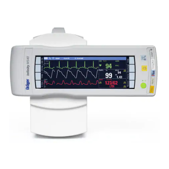
Page 1
Instructions for use Infinity Acute Care System Monitoring Applications WARNING Software VG6.n To properly use this medical device, read and comply with these instructions for use.
Typographical conventions Consecutive numbers indicate steps of action, with the numbering restarting with “1” for each new sequence of actions. Bullet points indicate individual actions or diffe- rent options for action. – Dashes indicate the listing of data, options, or objects.
® – Klorsept – Microsoft Edge is a trademark of Medentech. are either registered trademarks or trademarks of Microsoft Corporation in the United States and/or ® – Virkon other countries. is a trademark of DuPont. – Citrix Receiver ® – SERVO-i ®...
Page 5
Safety information definitions NOTE WARNING A NOTE provides additional information intended A WARNING statement provides important in- to avoid inconvenience during operation. formation about a potentially hazardous situation which, if not avoided, could result in death or serious injury. Abbreviations and symbols CAUTION For explanations, refer to sections "Abbreviations"...
Definition of target groups Target groups for this product include users, Service personnel service personnel, and experts. Service personnel are persons who are responsible These target groups must have received instruction for the maintenance of the product. Service in the use of the product and must have the personnel must be trained in the maintenance of necessary training and knowledge to use, install, medical devices and install, reprocess, and...
Page 8
Contents Configuring the alarm message behavior..131 Connecting the lead wires for neonatal Configuring the arrhythmia alarm setup ..134 monitoring ......203 Alarm setup for ST .
Page 9
Contents Ventilation parameter setup functions ..248 Non-invasive blood pressure display..294 Non-invasive blood pressure measurement SpO2 and Pulse CO-Ox monitoring with modes ....... 296 Masimo SET MCable .
Page 10
Contents Connecting the CO sensor ....340 External devices – MEDIBUS.X devices . . . 401 Patient preparation for CO monitoring ..341 External device monitoring .
Page 11
Contents Screen setup – general settings ... . 445 Temperature ......537 Screen setup –...
Page 12
This page has been left blank intentionally. Instructions for use – Infinity Acute Care System – Monitoring Applications VG6.n...
For your safety and that of your patients For your safety and that of your patients Strictly follow these instructions for use ..14 Storing the instructions for use ... . . 14 Training.
Training for users is available from the responsible NOTE Dräger organization, see www.draeger.com. The Infinity Acute Care System provides the fol- lowing additional instructions for use: – Infinity Acute Care System – Infinity M540 Maintenance patient monitor (describes the M540 user interface) WARNING –...
For your safety and that of your patients Installing accessories Connected devices CAUTION WARNING Risk of device failure Risk of electric shock and of device malfunction. Install accessories to the basic device in accordance with the instructions for use of the Any connected devices or device basic device.
For your safety and that of your patients Connection to hospital network WARNING The leakage current increases when multiple Many medical devices manufactured by Dräger use medical devices are connected to a patient. networks to transmit patient data in real-time and to Make sure that the galvanic isolation of each notify clinical users of alarm conditions.
For your safety and that of your patients Patient monitoring The user of the medical device is responsible for choosing a suitable patient monitoring system that provides appropriate information on medical device performance and patient condition. Patient safety may be achieved by a wide variety of means ranging from electronic surveillance of medical device performance and patient condition to direct observation of clinical signs.
For your safety and that of your patients General safety information The following WARNING and CAUTION CAUTION statements apply to general operation of the Read all cleaning instructions (for example, medical device. originating from the disinfectant manufacturer and WARNING and CAUTION statements specific to the hospital) carefully before cleaning the device.
For your safety and that of your patients Not for use in areas of explosion hazard Operating location Only use devices (monitor, MPod, MCable, and WARNING accessories) in areas that meet the environmental Risk of explosion requirements outlined in the technical data section. This medical device is neither approved nor certified for use in areas where oxygen WARNING...
For your safety and that of your patients Electrosurgery CAUTION To avoid damaging the touch-sensitive screen, do Observe the following precautions during not allow sharp instruments to touch the front of electrosurgery to reduce electrosurgical unit (ESU) the devices. interference and improve user safety and patient safety.
For your safety and that of your patients Security recommendations Dräger makes the following security recommendations: – Physical security of the patient monitors is rec- ommended and is the responsibility of the oper- ating organization. – Physical security of the telecommunications closet is recommended and is the responsibility of the operating organization.
Page 22
This page has been left blank intentionally. Instructions for use – Infinity Acute Care System – Monitoring Applications VG6.n...
Application Intended use The IACS is intended for multi-parameter, The IACS and any connected optional hardware physiologic patient monitoring of adult, pediatric, are not intended for use in the following hospital and neonatal patients in environments where environments: patient care is provided by trained health care –...
Infinity PS250 power supply unit (PS250) . . 27 Infinity P2500 power supply unit (P2500). . . 27 Infinity M540 patient monitor (M540) ..28 Infinity M500 docking station (M500) ..28 Front view of the M500 .
Some terms used in these instructions for use: – Cockpit – refers to the Infinity C700 Medical Cockpit or the Infinity C500 Medical Cockpit. – M540 – refers to the Infinity M540 transport component and patient connection point of the IACS.
System overview Infinity PS250 power supply unit (PS250) The following diagram shows the bottom of the A Infinity network connectors PS250. B Nurse call connector C Export protocol connector D Power cable connection E Two interchangeable system cable connectors – one for the M540, one for the Cockpit F Network connection LEDs The front of the PS250 has the following two LEDs: –...
System overview Infinity M540 patient monitor (M540) The following diagram shows the M540 when it is A M540 patient monitor docked in the M500 docking station. B M500 docking station The M540 acquires patient signals, processes them, and relays them to the Cockpit for display.
System overview Rear view of the M500 A System cable connector B Nurse call connector C LED – lights up green when connected to the network Additional hardware The following table lists the additional devices that can be connected to the IACS. Device Description Connection...
Page 30
O, and anesthetic agents connector of the M540 (see the (Sevoflurane, Desflurane, instructions for use Infinity Acute Isoflurane, Halothane, and Care System – Infinity M540). Enflurane) in the breathing gas. Scio Four Oxi Measures the concentration of O, O and anesthetic...
Page 31
System overview Device Description Connection Infinity MCable – Analog/Sync Provides a sync pulse to Connects to the Temp/Aux synchronize defibrillators to the connector of the M540 (see heart beat of the patient during page 283) or to the CO cardioversion. The cable’s analog connector with a Y-cable.
System overview Device symbols Warning! Strictly follow these Lower alarm limits instructions for use Consult instructions for use Upper alarm limits Caution! Observe the accompanying Autoset alarm limits documentation! Directive 93/42/EEC Alarm monitoring deactivated concerning Medical Devices temporarily Access to trend pages Alarm monitoring deactivated permanently The button next to this symbol...
Page 33
System overview Access to the standby and privacy Change clinical password modes, and access to patient Change biomed password discharge Access to pre-configured views and Lung symbol that pulsates with each layouts detected breath Access to parameter pages Heart blip that flashes with each detected pulse Adult patient category Pediatric patient category...
Page 34
System overview Function/setting is unlocked Component number and revision Function/setting is locked Device serial number Data entry with numeric keypad Date of manufacture Trend configuration Complete screen calibration procedure Keyboard access Repeat screen calibration procedure Nurse call Display filter. When selected, only the connected parameters and associated setup pages are displayed.
Page 35
System overview Parameter is represented as a Import functions (for example, importing waveform and a parameter field profiles) Save modifications (for example, ESD warning changes to a view) Save as symbol IPXx Degree of protection against solid particle and liquid ingress, e.g., IPX1, IPX4, etc.
System overview Not made with natural rubber latex Not made with natural rubber latex Not made with natural rubber latex Do not re-use, single patient use Keep away from sunlight Do not re-use Caution: This product contains natural rubber latex which may cause an allergic reaction Abbreviations The following table lists the abbreviations used in...
Page 37
System overview Abbreviation Description Abbreviation Description ECG lead aVR dV1 to dV6 Derived chest leads AW-Temp Gas temperature (airway) Digital visual interface Burst count Lung elastance Bispectral index Electrocardiogram Bigeminy End-diastolic volume BRADY Bradycardia EDVI End-diastolic volume index Body surface area Ejection fraction Suppression ratio End inspiratory pressure...
Page 38
System overview Abbreviation Description Abbreviation Description Height inIso Inspiratory isoflurane concentration Hemoglobin inxMAC MAC factor Heart rate inN2O Inspiratory N2O concentration ECG lead I inSev inspiratory sevoflurane IACS Infinity Acute Care System – concentration Monitoring Applications Insp. term. Inspiratory termination criterion Inspiratory to expiratory ratio based on peak inspiratory flow I (I:E)
Page 39
System overview Abbreviation Description Abbreviation Description MVspon Minute volume, expired Plow Lower pressure level during spontaneous APRV Nitrous oxide Pulse rate from SpO2 N2O cons Cumulated N2O consumption Arterial blood pressure – pulse rate NIBP Non-invasive blood pressure Pmax Maximum inspired pressure NIBP D NIBP diastolic value Pmean...
Page 40
System overview Abbreviation Description Abbreviation Description Rate pressure product Signal quality index Respiratory rate (CO ST(x) ST deviation of lead (x) Respiratory rate (impedance) STdV1 ST-segment deviations of derived STdV3 leads RRmand Mandatory respiratory rate STdV4 Respiratory rate, spontaneous STdV6 RRspon Respiratory rate, spontaneous Stroke volume...
Page 41
System overview Abbreviation Description Abbreviation Description TVd aw Tidal volume, dead space VTspon Spontaneous tidal volume, leakage-corrected Vds/VTe Tidal volume, relative dead space Vtrap Trapped volume Tidal volume, inspired VT/Wt Tidal volume per kg body weight Total vascular resistance Chest lead from a 5- or 6-wire lead set.
Page 42
This page has been left blank intentionally. Instructions for use – Infinity Acute Care System – Monitoring Applications VG6.n...
Operating concept Overview The IACS is a fully networked solution that offers patient monitoring, therapy, and IT applications at the point of care. Dräger developed the IACS to solve problems common in the acute care environment. As a result, the IACS provides standardized user interfaces, improves workplace ergonomics and flexibility, and centralizes patient data at the point of care.
Operating concept The IACS components The following diagram shows a possible IACS configuration. A C500/C700 K AC power B DVI cable L Infinity network C Secondary display (option) M Infinity MCable – Nurse call (option) D USB cable N P2500 / PS250 E Keyboard and mouse (option) O Hospital network F Device connectivity cable (option)
Operating concept M540 and Cockpit communication Docking the M540 Communication between the M540 and the Cockpit starts as soon as the M540 is docked in the M500 (see page 93). The M540 acquires physiological As soon as the user docks the M540 in the M500, signals from the patient and relays them to the the following happens at the Cockpit: Cockpit for display.
Operating concept Undocking the M540 Docking to a different Cockpit CAUTION When the user undocks the M540, the following Before connecting the M540 to a different happens: Cockpit, make sure that the units of measure align – The message Disconnected from M540 between the two devices.
80 seconds For detailed information on how the M540 behaves between each other. in standalone mode, see the Instructions for use entitled Infinity Acute Care System – Infinity M540. Instructions for use – Infinity Acute Care System – Monitoring Applications VG6.n...
Operating concept Network data transfer The IACS supports the transfer of patient data to and from the following devices assigned to the same monitoring unit: – Infinity Delta/Delta XL/Kappa (software version VF7 to VF9.x) – Other IACS monitoring Cockpits NOTE You can also transfer patient data by undocking and redocking an M540.
Page 50
Operating concept 9 Select one of the following buttons: CAUTION – Cancel – to prevent the data transfer and To prevent mixing the data of two patients, first return to the Transfer page. discharge the patient admitted at the destination Cockpit.
Operating concept Remote control and remote view When a Cockpit is connected to the Infinity and perform several remote functions. The user network, data can be shared among Infinity devices can also allow other Infinity devices to view a that are connected to the network. From the Cockpit and perform remote functions by activating Cockpit, the user can view other Infinity devices the remote control function (see page 475).
Page 52
Operating concept Views... A Disconnect button B Audio Pause button C Continuous Recording button D Timed Recording button Instructions for use – Infinity Acute Care System – Monitoring Applications VG6.n...
Operating concept Network communication interruptions Using remote view functions From the Remote view dialog, the user can When the Cockpit loses communication with the perform the following functions: ICS, the following happens at the Cockpit when the – Select the Disconnect button (A) to exit the Enable Central Station setting is activated (see remote view.
Operating concept Remote control If the remote control feature is activated (see – Request timed and continuous recordings page 475), the user can perform the following – Audio pause acoustic alarm signals Cockpit functions remotely from the ICS: If several devices modify the patient settings of a NOTE single Cockpit, the last update is always Remote control of arrhythmia settings from ICS is...
Page 55
Operating concept What happens if... Behavior the user docks an M540 and it is unable to – An alarm of medium priority sounds at the Cockpit, communicate with the Cockpit? at the M540, and at the ICS (provided the patient is admitted there).
Page 56
Operating concept What happens if... Behavior the Cockpit loses communication with the When the setting Enable Central Station is activated ICS? (see page 475), the following happens at the Cockpit: – On the Cockpit the Alarm volume setting (see page 458) changes to 100% volume regardless of whether an alarm condition exists or not.
Operating concept Loss of power A loss of power has the following effect: – A medium-priority alarm is triggered at the Cockpit and the message please plug in – The Cockpit switches to battery charge for up to power supply appears. five minutes before performing a safe shutdown that preserves the integrity of the patient data –...
Operating concept Secondary display To extend the display capabilities of a Cockpit, connect a secondary display to the DVI connector Display Resolution of the Cockpit using a DVI to DVI to VGA cable C500 (2 generation) 1440 x 900 pixels type.
Operating concept User interface The following sections describe the user interface of the Cockpit when it is connected to an M540. The screen of a monitoring Cockpit is divided into the following main areas: A Header bar B Main menu bar C Auto view toolbar (if activated) D Monitoring area For a more detailed overview of general user...
Operating concept Header bar The blue header bar appears along the top of the The patient name field Cockpit screen. It is always visible regardless of The patient name field (C) of the header bar what is displayed in the monitoring area. displays the patient name.
Operating concept The alarm status field The alarm status field (F) of the header bar (see page 509) indicates the current alarm status. The following are some examples of alarm-related symbols and messages that can appear in this field. Symbol Label Description Audio paused...
Operating concept Parameter fields Each parameter field contains real-time values of a The following example shows how the same parameter and a combination of the following parameter field changes when more parameters information: occupy the main screen. Each parameter field has less space to display its content.
Operating concept – Changing the colors for individual parameters NOTE (see, for example, how to change the color for If the acquired signal does not fit in the waveform ECG on page 214) channel, the top of the waveform may appear clipped.
Operating concept Dialogs and pages The following diagram shows how the monitoring Selecting the corresponding button followed by area appears when the user accesses a dialog. dots on the main menu bar opens the The left side is reserved for the dialog while the corresponding dialog.
Operating concept Main menu bar and quick access toolbar The following diagram shows the main menu bar The following buttons appear on the main menu with the quick access symbols and a quick-access bar. toolbar. The main menu bar and the quick-access Alarms...
Operating concept Quick access toolbar Functions that are commonly used are grouped on The following table lists the quick access symbol quick access toolbars for easy access. These quick and the associated toolbar they open when access functions are accessible by selecting the selected.
Operating concept Filtering the parameter content To filter the content of the displayed parameters, The filter button toggles between an unfiltered and use the display filter button which appears in filtered display. The filter is activated when the the following dialogs: display filter button appears on the light green background.
Operating concept Auto view setup toolbar When the auto view mode is activated (see It functions dynamically with the Auto view page page 446), the auto view setup toolbar appears (see page 446) where the user selects the along the bottom of the screen. The auto view setup maximum number of waveforms and parameter toolbar is for configuring the parameter priority and fields and determines the parameter priority.
Operating concept Cockpit screen in split screen mode The following diagram shows the Cockpit display parameters while the left panel displays either a when the following options/features are activated: tabular trend, loops, ECG show all page, ECG/ventilation, ECG/ST, or ST parameters (see –...
Operating concept Cockpit split screen mode with mini-trends The following diagram shows the Cockpit display If the split screen mode is not activated, the mini- when the following options/features are activated: trend panel shifts to the left edge of the screen. –...
Operating concept Cockpit split screen mode with multi-tab split screen The following diagram shows the Cockpit display when the Multi-tab split screen feature is activated by itself (see page 447). A Header bar B Main screen menu bar C Monitoring area with real-time vital signs D Multi-tab split screen –...
Operating concept Cockpit split screen mode with mini trends and IT tabs The Cockpit supports IT applications that are – The Mini trends feature is activated (see accessible via tabs. page 447). The following diagram shows the Cockpit display Once the application is configured and the IT when the following options are unlocked and the application feature is activated (see page 479), the features are activated:...
Operating concept Parameter priority The parameter priority determines what position a The following list shows the default parameter parameter occupies on the screen. The number of priority list. Pressures without assigned labels parameters appearing as waveforms and appear as GP1, GP2, GP3, or GP4. parameter fields depends also on the selected 1 ECG Waveforms setting (see page 447).
Operating concept 27 Vent 30 BIS (not available in neonate mode) 28 O (MEDIBUS.X) 31 NMT 29 Agent (MEDIBUS.X) 32 CO-Ox Views The view editor Each Cockpit supports eight pre-configured Dräger views and, as an option, up to eight custom views. Views control the content and appearance of the The view editor (option) allows authorized screen.
Operating concept Profiles/status Cockpits are adaptable to different care areas. This Profiles are divided into the following two adaptability is partially due to profiles which allow categories: clinical personnel to create unique setups for the – Patient and default profiles patient population of specific care areas.
Operating concept Settings included in a profile The following table lists all of the settings included Parameter Included settings in a patient profile. For details on each setting, such ST monitoring as available selections and detailed descriptions of (see page 234) the setting, refer to the cross-referenced pages.
Page 77
Operating concept Parameter Included settings Parameter Included settings SpO2 (Masimo SET Pulse tone volume Invasive blood Scale and Masimo pressure Tone source Filter Rainbow SET) Averaging time Large mean FastSat mode Min. scale (ICP) Waveform size [%] Color Color Alarm on/off setting Alarm on/off setting Alarm limits Alarm limits...
Page 78
Operating concept Parameter Included settings Parameter Included settings Scale Scio Agent Agent selection (for variants (see page 365) with manual identification RRc apnea time [s] only) RRc apnea archive Agent parameter field Color configuration Airway adapter Agent/xMAC mini trend configuration Averaging Alarm status Alarm on/off setting...
Page 79
Operating concept Parameter Included settings Parameter Included settings External devices – Vent parameter display Alarm profile settings ventilator (Medibus setting (see page 415) Alarm system All alarms paused Parameter 1 (vent, paw) settings Show alarm limits (see page 401) (see page 458) Parameter 2 (vent, paw) Cardiac bypass Parameter 3 (vent, paw)
Page 80
Operating concept Parameter Included settings Configurable views Up to eight available, (see page 451) configurable views Config. buttons Button setup (see page 452) Multi-tab split Tab 1, Tab 2, or Tab 3 screen (see page 455) Screen system Monitoring sweep speed settings [mm/s] (see page 445)
Operating concept Settings not included in a profile The following settings are not included in a profile and must be configured separately. These settings remain unchanged until they are manually changed again by the user. Parameter/system fea- Setting ture Non-invasive blood Venous stasis pressure Continuous mode...
Operating concept System profiles System profiles are system-wide settings. System Most system settings can be shared and are also profiles are divided into the following two install persist settings. However, some settings are categories: install persist settings only which are identified in the following table.
Page 83
Operating concept Setting Shared and install persist settings Install persist only settings Alarm Waveform Primary Recorder Secondary Recorder Report setup settings (see page 470) Waveform delay [s] Waveform duration [s] Trend duration [hr] Table interval [min] Biomed printer settings (see page 477) Printer IP address HP Universal Print Driver Paper Size...
Page 84
Operating concept Setting Shared and install persist settings Install persist only settings Biomed Infinity network settings (see page 476) IP address Subnet mask Gateway Offline detection Primary DNS Duplicate IP check IP check interval [s] Biomed hospital network settings (see page 476) DHCP IP address Subnet mask...
Page 85
Operating concept Setting Shared and install persist settings Install persist only settings Value of up to 32 applications Auto logoff Tab visible Graphical trend settings (see page 164) View Graphs Grids Tabular trend settings (see page 164) View Calculation parameters (see the ’Calculations’ chapter starting on page 184) All hemodynamic parameters All oxygenation/ventilation...
Operating concept Managing profiles and views Transferring profiles Each patient category (adult, pediatric, neonatal) has its own unique profile. For example, if the neonatal patient category is activated, only the Profiles can be transferred to other Cockpits in the profiles defined for the neonatal patient category password-protected Profile transfer page.
Operating concept Standby mode Temporarily interrupt patient monitoring by placing To place the Cockpit in standby mode the Cockpit and the M540 in standby mode. 1 Select the symbol next to the Selecting standby mode on the Cockpit Start/Standby... button on the main menu bar automatically activates standby mode on the M540 to display the Standby toolbar.
Operating concept Privacy mode Privacy mode is possible only when the patient is To place the Cockpit into privacy mode admitted at the Infinity CentralStation (ICS). In 1 Select the symbol next to the privacy mode, patient monitoring continues but the Start/Standby...
Operating concept Screen lock The screen lock feature allows the user to disable the touchscreen via a Screen lock control. Screen lock enables the user to move or clean the Cockpit without unintentionally triggering changes on the touchscreen. To activate screen lock 1 Select the Start/Standby...
Page 90
This page has been left blank intentionally. Instructions for use – Infinity Acute Care System – Monitoring Applications VG6.n...
Assembly and preparation Assembly overview Commercially available mounting This chapter describes the following basic assembly tasks: solutions – Docking/undocking the M540 from the M500 Various mounting solutions are available. It is the responsibility of the hospital to install, test, and –...
Assembly and preparation Docking/undocking the M540 The following diagram shows the front and side of To dock the M540 the M500 which holds the M540 in place. 1 Align the curved portion of the M540 with the curved portion of the M500. Front view of the M500 (M540 docked) 2 Press the M540 (C) into the M500 (D) until it ‘clicks’...
Assembly and preparation Locking/unlocking the M540 You can lock the M540 in the M500 to prevent any- To unlock the M540 one from undocking it. 1 Insert the 2 mm hex wrench tool (A) into the middle hole (B) on the locking tab and turn it To lock the M540 into place counterclockwise to the unlocked position 1 Push the locking tab (D) of the M500 towards...
Assembly and preparation Additional M540 accessories The M540 patient monitor supports a variety of more information about these specialized accessories that include transport hardware, accessories, refer to the Infinity Acute Care System clamps, cable hooks, trolleys, and so forth. For –...
Assembly and preparation Connecting the system cable to the PS250 / P2500 and the M500 1 Connect one end of the system cable (B) to the M500 system connector. 2 Connect the other end of the system cable to one of the two PS250 / P2500 system connec- tors (see diagram on page 95).
Assembly and preparation Mounting the Infinity MCable – Masimo SET/Masimo rainbow SET/ Nellcor OxiMax The following diagram shows how a Masimo MCable can be mounted to the M540. The Nellcor OxiMax MCable can be mounted in the same way. Side view (connectors) Bottom view A M540 E Blue SpO2 connector...
Page 98
Assembly and preparation To attach the MCable mount adapter Follow these steps to attach the MCable to the M540: 1 Make sure the cable end of the MCable (D) mount adapter (C) points in the same direction as the connector side of the M540. 2 Align the tabs on the mount adapter (B) with the indentations on the M540 and push firmly until the mount adapter clicks in place.
Getting started Overview This chapter describes the necessary steps to start Specifically, this chapter describes how to: monitoring a patient on the IACS. – Turn the IACS on/off – Admit/discharge a patient on the Cockpit – Change the patient category Turning the IACS on/off Before monitoring a patient on the IACS, the To turn the M540 on...
Getting started To turn the Cockpit off To turn the M540 off 1 Press the on/off key located in the lower left 1 Press and hold the on/off key. The power off corner of the Cockpit dialog appears. 2 Select the Shutdown button in the dialog. 2 Select the Shutdown button in the dialog.
Getting started Admitting a patient You can admit a patient at the Cockpit manually by 4 Enter the patient ID – use the symbol (C) next entering the demographic data on the to the Patient ID field to activate a keyboard for Demographics page.
Refer to the instructions for use Infinity Acute Care System – Infinity M540, for detailed information on how to discharge a patient from the M540. Discharging a patient has the following effect on the Cockpit: –...
Getting started To discharge a patient 3 Select the Start button. A pop-up window with the message Caution discharge will delete 1 Select the left most field on the header bar of patient data appears. the Cockpit to access the Demographics page. 4 Select the Discharge button in the pop-up 2 Select the Start tab (if not already selected).
Getting started Selecting the patient category If the Patient profile selection function is activated The Cockpit switches to the new patient category (see page 473), you can change the patient and the selected profile. category and select a profile from a list of pre- configured profiles from the Start page.
Page 106
This page has been left blank intentionally. Instructions for use – Infinity Acute Care System – Monitoring Applications VG6.n...
Cockpit. All alarm conditions functions of the M540, refer to the instructions for and associated alarm messages are described in use Infinity Acute Care System – Infinity M540. detail in the "Troubleshooting" chapter starting on WARNING page 509.
MCable, any parameter displayed on the Cockpit instructions for use Infinity Acute Care System – using the device connectivity option. Infinity M540). When you undock the M540 from the M500 (see The Cockpit provides acoustic and optical alarm page 93), all alarm monitoring stops at the Cockpit signals for parameters originating from monitors in but continues on the M540.
Alarms Latching and non-latching alarm behavior When an alarm condition no longer exists, the To acknowledge a latched alarm condition associated acoustic and optical alarm signals Press one of the following two keys: behave in one of two ways: – The yellow key on the front of the –...
Alarms Activating or deactivating alarm validation When the alarm validation function is activated (see validation delay. For HR, adding the delay time may page 445), an alarm condition must exist for a exceed the maximum of 10 seconds allowed per certain time before acoustic and optical alarm AAMI/ANSI/IEC 60601-2-27.
Alarms Optical alarm signals Each alarm priority has its own distinct optical alarm The alarm message in the header bar is the only signals. When the M540 is docked on the M500, optical alarm signal if an alarming parameter is not only the Cockpit provides acoustic alarm signals.
Alarms Optical alarm indicators on the Cockpit Optical alarm indicators on the M540 A Alarm message field in the blue header bar B Alarming parameter field C Alarm bar Alarm bar The alarm bar on the Cockpit and the M540 Header bar optically announces high and medium-priority The header bar displays the alarm message on the...
Alarms Acoustic alarm signals During an alarm, the Cockpit also provides distinct NOTE acoustic alarm signals for each alarm priority in Normally, acoustic alarm signals only sound at the addition to optical alarm signals (see page 112). Cockpit not at the M540. Therefore, all acoustic The specific characteristics of these acoustic alarm alarm signals are transferred automatically from signals depend on the selected alarm tone pattern.
Alarms Attention tones Special conditions affecting the alarm volume The Cockpit also provides an attention tone to alert you to special information such as: There are several conditions that affect the alarm volume of the Cockpit. – Start of venous stasis –...
Alarms Deactivating the alarm volume To deactivate the alarm volume Make sure the Minimum alarm volume is set to You can only deactivate the alarm volume under Off (see page 461), before you execute the the following two circumstances: following steps: –...
Alarms To access the current alarm messages Select the More... button to the left of the alarm 1 Select the Alarms... button on the main menu message field in the header bar (only visible bar. when more than two patient alarm conditions 2 Select the Current alarms tab.
Alarms Zeroing invasive blood pressures Privacy mode Zeroing all invasive blood pressures from the Zero When privacy mode is activated, the following all button on the Cockpit menu bar or from the happens at the Cockpit: key on the hemodynamic pods (see page 314) has –...
Alarms Cardiac bypass mode OR alarms Cardiac bypass mode is only available when the Cockpit is in OR mode. When cardiac bypass mode is activated (see page 460), the following happens When OR alarms are activated, alarm messages at the Cockpit: for medium and high-priority alarms clear when the alarm condition no longer exists.
Alarms Pre-silencing alarms Initiating a pre-silence period This function allows you to pre-silence (audio pause in advance) potential alarm conditions before they occur. Pre-silencing allows you to You can initiate a pre-silence in several ways: concentrate on a procedure without being –...
Alarms To pre-silence alarms remotely Press the yellow key on the main menu Refer to the instructions for use of other remote bar of the ICS to pre-silence alarms for all devices within the same monitoring unit for assigned patients.
Page 122
Alarms Initiating an audio pause The following happens when you pause active To initiate an audio pause from the Cockpit alarms: Press the yellow key on the – The alarm tone is paused for two minutes Cockpit. The appearance of the yellow key depends on the Cockpit hardware version (see –...
Alarms Activating or deactivating acoustic alarm signals Deactivating acoustic alarm signals is a password- After deactivating acoustic alarm signals protected function (see page 458). permanently, you can activate them again (see page 458). When you activate acoustic alarm You can deactivate alarm tones permanently. When signals, the following happens when an alarm you deactivate alarm tones, the following happens: condition occurs:...
Alarms To pause alarm monitoring temporarily To activate alarm monitoring after pausing 1 Select the symbol next to the Alarms... but- 1 Select the symbol next to the Alarms... but- ton on the main menu bar of the Cockpit. ton on the main menu bar of the Cockpit. 2 Select the All alarms paused button.
Alarms To deactivate alarm monitoring permanently To activate alarm monitoring after deactivating 1 Select the symbol next to the Alarms... but- 1 Select the symbol next to the Alarms... but- ton on the main menu bar of the Cockpit. ton on the main menu bar of the Cockpit. 2 Select the All alarms off button on the toolbar.
Alarms Setting the upper and lower alarm limits When you deactivate alarms, no acoustic and optical alarm signals are triggered for that parameter. When alarm monitoring is deactivated, You can configure the upper and lower alarm limits a crossed out triangle (A) appears in the parameter of a parameter manually to trigger acoustic and field.
Alarms Configuring the alarm setup for an individual parameter If you are only changing the alarm settings of an A Alarm on/off buttons for each parameter individual parameter, use the parameter-specific B Auto set button setup page which includes the alarm setup. C Buttons setting the upper limits for each param- The following diagram shows an example of a eter...
Alarms Changing alarm settings for a single parameter In the steps below, the letters in parentheses refer 3 Select the Alarm on/off button (A), to activate or to the diagram of the parameter-specific setup deactivate alarm monitoring. A crossed-out page. triangle appears in the parameter field when alarm monitoring is deactivated.
Alarms Configuring the alarm setup for multiple parameters The following diagram shows the General page A Limits tab where you configure alarm settings for all available B Parameter labels column parameters. The page consists of a table with setup rows for each parameter. Each setup row consists C Alarm on/off column of several fields for configuring the individual alarm D Lower limits column...
Page 130
Alarms Changing general alarm settings In the following steps, the letters in parentheses 7 Select the corresponding button in the Upper refer to the diagram of the General page (see column (F) to adjust the upper alarm limits. page 129). Alarm ranges and defaults are listed 8 Use one of the following settings in the Archive starting on page 160.
Alarms Configuring the alarm message behavior The Config. tab allows you to set up the acoustic The alarm setting: and optical alarm signal reporting behavior in – is supported on the ICS response to certain SpO2 sensor and messages related to leads-off conditions. –...
Page 132
Alarms Message Available settings Description Archive settings SpO2 sensor off – Off (default) The archive settings cannot be configured for these two alarm messages. The archive setting follows SpO2 check sensor – Store the general archive status for the parameter. For –...
Page 133
Alarms Message Available settings Description RRi lead off Alarm settings – High Assigns an alarm priority to the RRI lead-off alarm or deactivates it. – Medium – High: The event is treated as a high-priority – Low (default) alarm. – One-shot –...
Alarms Configuring the arrhythmia alarm setup The following diagram shows the Limits > ARR A Limits tab page for configuring the alarm settings for B Arrhythmia category column for identifying the arrhythmia parameters. This page consists of a ARR label table with setup rows for each arrhythmia parameter.
Alarms To change ARR alarm settings 1 Select the Alarms... button on the main menu 7 Use one of the following settings in the Archive bar. column (F) to determine what happens in response to an alarm: 2 Select the Limits tab (if not already selected). –...
Page 136
Alarms Limits tab Alarms B Parameter label column C Alarm on/off column D Lower limits column E Actual parameter values F Upper limits column G Archive column H ST tab Auto set all button J Event duration [s] button K ST relearn button Instructions for use –...
Page 137
Alarms Configuring ST alarm settings Some of the ST alarm settings described are also 6 Select the corresponding setup button in the available on the ST alarms page (see page 233). In Upper column (F) to adjust the upper alarm the following steps, the letters in parentheses refer limits.
Alarms Auto setting all alarm limits The auto set function allows you to adjust alarm You can either auto set: limits quickly based on preset percentages listed in – individual parameters (see page 139) the following table. – all parameters (see page 139) –...
Alarms To auto set an individual parameter To auto set all parameters 1 Select the parameter field of the desired param- Select the symbol next to the Alarms... eter. button on the main menu bar > Auto set all. 2 Select the Auto set button located in the upper- right corner of each parameter setup page.
Page 140
Alarms Alarm history after shutdown A Alarm history tab B Identifies an event The alarm history is maintained until the patient is discharged. If the Cockpit is turned off and turned C Date of the alarm back on, the patient’s alarm history is not affected. D Time the alarm was stored However, the alarm history will not record the time of the shut down.
Alarms Viewing a snapshot of a single event 20 seconds of waveform and parameter data are The following diagram shows the event snapshot stored automatically in the alarm history under the screen. following circumstances: Alarms – A parameter whose recording archive feature is set to Store or Str/Rec (see page 126) violates set alarm limits.
Alarms Viewing current alarms The Current alarms page displays all alarms that To view current alarms occur during a patient’s monitoring session. The 1 Select Alarms... on the main menu bar. page is cleared when the patient is discharged. Each alarm displays the alarm priority, the duration, 2 Select the Current alarms tab.
Alarms Selection Available settings Description Show alarm limits – On (default) Determines whether alarm limits appear in the parameter fields. – Off Cardiac bypass – On Activates/deactivates cardiac bypass mode. Alarm functions are affected when cardiac – Off (default) bypass mode is activated (see page 119). This mode is not available when the French NFC mode is enabled (see page 473).
Alarms Configuring the alarm priority for a The following SpO2 parameters can generate this alarm message according to the selected alarm Nellcor check sensor message priority: This alarm setting is for configuring the alarm Masimo rainbow SET Masimo SET MCable priority and the alarm archiving behavior of certain MCable Nellcor SpO2 parameters.
Alarms Alarm groups Configuring remote patient monitor alarms The Cockpit can receive alarm messages from other monitors that are connected to the Infinity The following table contains settings that enable network. However, these monitors must be in the remote patient monitor alarms that are on the IACS same monitoring unit and in the same alarm group network to be viewed at the Cockpit.
Alarms Selection Available settings Description Alarm group Keypad for configuring an alarm Allows you to configure several monitors as group. members of a group. All alarms that occur at any of the monitors within the group are broadcast to all other members in the alarm group.
Alarms External device disconnection alarm If the external device alarm feature is activated at – An alarm tone of low priority sounds. the Cockpit (see page 461) and an external device – The message External device disconnected is disconnected from the Cockpit, the following appears.
Alarms The Timer function The Timer function appears similar to the Code function but serves as a stopwatch only. No other functions are tied to the Timer button. When the Timer function is activated, a timer appears in the header bar with the following two buttons: –...
Alarms Alarm ranges and defaults Parameter Alarm Alarm limit range Upper limit Lower limit Archive default defaults defaults default status setting HR adult Upper: 25 to 300 bpm 120 (adult) 45 (adult) Str/Rec (adult/ Increment: Lower: 20 to 295 bpm 150 (pediatric) 50 (pediatric) pediatric)
Page 150
Alarms Parameter Alarm Alarm limit range Upper limit Lower limit Archive default defaults defaults default status setting SpO2 Upper: 21 to 100% 100% (adult, pediatric) Increment: 1 Lower: 20 to 99% NOTE: 95% (neonate) Changing this set- ting auto- matically changes Desat.
Page 151
Alarms Parameter Alarm Alarm limit range Upper limit Lower limit Archive default defaults defaults default status setting NIBP S adult Upper: 11 to 250 mmHg 160 mmHg 90 mmHg Increment: 1.5 to 33.3 kPa 21.3 kPa 12.0 kPa 1 mmHg or Lower: 10 to 249 mmHg 0.1 kPa 1.3 to 33.2 kPa...
Page 152
Alarms Parameter Alarm Alarm limit range Upper limit Lower limit Archive default defaults defaults default status setting NIBP M pediatric Upper: 11 to 170 mmHg 85 mmHg 40 mmHg Increment: 1.4 to 22.7 kPa 11.3 kPa 5.3 kPa 1 mmHg or Lower: 10 to 169 mmHg 0.1 kPa 1.3 to 22.6 kPa...
Page 153
Alarms Parameter Alarm Alarm limit range Upper limit Lower limit Archive default defaults defaults default status setting IBP S pediatric/ Upper: –24 to +300 mmHg – 120 mmHg – 50 mmHg neonate (16.0 kPa) (6.7 kPa) –3.2 to +40.0 kPa for GP1 S to for GP1 S Increment:...
Page 154
Alarms Parameter Alarm Alarm limit range Upper limit Lower limit Archive default defaults defaults default status setting IBP D neonate Upper: –24 to +300 mmHg – 80 mmHg – 35 mmHg (10.7 kPa) (4.7 kPa) Increment: –3.2 to +40.0 kPa for GP1 D to for GP1 D 1 mmHg...
Page 155
Alarms Parameter Alarm Alarm limit range Upper limit Lower limit Archive default defaults defaults default status setting IBP M pediatric Upper: –24 to +300 mmHg – 80 mmHg – 50 mmHg (10.7 kPa) (6.7 kPa) Increment: –3.2 to +40.0 kPa for GP1 M to for GP1 M 1 mmHg or...
Page 156
Alarms Parameter Alarm Alarm limit range Upper limit Lower limit Archive default defaults defaults default status setting Upper: –24 to +300 mmHg 100 mmHg 70 mmHg (13.3 kPa) (9.3 kPa) Increment: –3.2 to +40.0 kPa 1 mmHg Lower: –25 to +299 mmHg or 0.1 kPa –3.3 to +39.9 kPa Tblood...
Page 157
Alarms Parameter Alarm Alarm limit range Upper limit Lower limit Archive default defaults defaults default status setting inCO2 Upper: 2 to 10 mmHg 4 mmHg Not applicable Off (0.5 kPa, 0.5%) Increment of 0.3 to 1.3 kPa 1 mmHg, 0.3 to 1.3% 0.1 kPa, or 0.1 Lower: not user-selectable etCO2...
Page 158
Alarms Parameter Alarm Alarm limit range Upper limit Lower limit Archive default defaults defaults default status setting etIso Upper: 0.1 to 8.5 kPa 8.5 kPa, 8.5% 0.0 kPa, 0.0% Off Increment of 0.1 to 8.5% 0.1 kPa or 0.1% Lower: 0.0 to 8.4 kPa 0.0 to 8.4% inEnf Upper: 0.1 to 10.0 kPa...
Page 159
Alarms Parameter Alarm Alarm limit range Upper limit Lower limit Archive default defaults defaults default status setting inDes Upper: 0.1 to 20.0 kPa 12.5 kPa, 12.5% 0.0 kPa, 0.0% Store (adult) Increment of 0.1 to 20.0% 0.1 kPa or 0.1% 14.5 kPa, 14.5% Lower: 0.0 to 19.9 kPa (pediatric)
Alarms Arrhythmia ranges and defaults Parameter Alarm priority Rate (default) Count (default) Alarm archive default factory default High Not adjustable Not adjustable Str/Rec High Not adjustable Not adjustable Str/Rec ≥100 to 200 (≥120) ≥5 to 15 (≥10) VTACH High Str/Rec Increments of 10 Increments of 1 ARTF...
– selecting the time period of the trended Refer to the instructions for use Infinity Acute Care parameters. System – Infinity M540 for a detailed description of the M540 trend functions. The Cockpit maintains one trend database per patient. If the user docks an M540 that was...
Page 163
Trends/data dialogs Continuous parameters – Pulse oximetry parameters with Nellcor OxiMax MCable: SpO2, PLS The following parameters are continuously trended and appear as a single, continuous line, or as a NOTE band on the graphical trends (see page 36 for The color of the SpO2 graphical trend changes definitions of abbreviations): based on how the current value compares to the...
Trends/data dialogs Special characters and symbols In addition to parameters, certain conditions, such as disconnected leads, artifact, and so on, are also identified on graphical and tabular trends. Event Character/symbol Asystole Ventricular fibrillation Apnea Apnea No parameter values are * * * available Out of range value +++ (high) - - - (low)
Trends/data dialogs The layout of the graphical trends pages The graphical trends pages share a common A Trends tab layout. They contain up to four separate trend B Graph tab – accesses graphical trends windows. Each trend window can accommodate the graphical trends of up to five selectable C Table tab –...
Trends/data dialogs Interacting with the graphical trends pages You can interact with the graphical trends pages by manipulating several display functions. Configuring the parameter content of the graphical trends Except for the Graph vitals page whose parameter A Display filter button assignments are fixed, you can customize the B Button that closes the setup window parameter content for the Graph and the...
Trends/data dialogs Navigating through the graphical trends To modify the parameter selection for a graphical trend page The trend database for a patient may contain more In the following steps, the letters in parentheses data than can be displayed on a single graphical refer to the diagram of the trend setup page (see trend page.
Trends/data dialogs Changing trend scales Printing a graphical trend report The trend scales appear to the left of each trended The content of a graphical trend report depends on parameter. The scales can be changed at any time the user setup (see page 166). The duration of a provided the trend cursor is not displayed.
Trends/data dialogs Analysis tool page The Analysis tool page is a comprehensive trend Procedures page for visualizing information necessary to perform a recruitment maneuver. The page shows the effects on lung mechanics and hemodynamic parameters on a single, integrated display. The Analysis tool page displays a duration of data configured by the user on three graphical trend panels simultaneously.
Trends/data dialogs Interacting with the Analysis tool page Configuring the parameter content Although the Analysis tool page comes with an To configure the parameter content initial default parameter setup, the page can be 1 Select the Procedures... button from the main customized for the current monitoring session.
Trends/data dialogs Using the cursors The Analysis tool page has two cursors for In addition to values, symbols appear next to the marking a portion of the graphical trends for closer values to indicate how the parameters inside the analysis. The letters in parentheses refer to the cursors have trended: diagram on page 169.
Trends/data dialogs Selecting an interval Printing an Analysis tool graphical trend report The interval that applies to the three graphical trends can be set. A graphical trend report for recruitment contains the initial and end cursor values and the Δvalue for each parameter.
Trends/data dialogs The layout of the tabular trend The following diagram shows the tabular trend A Trends tab page. Configuring the tabular trend page also B Parameter label column determines how the information appears on the tabular trend report. C Parameter columns D Latest trend data Trends/Data E Graph tab (see page 169)
Trends/data dialogs Interacting with the tabular trend Navigating through the tabular trend Interaction with the trend screen involves manipulating several display functions. The trend data base for a patient may contain more data than can be displayed on the tabular trend. Tabular trends in split screen mode Use the scroll bars to navigate through the entire trend data.
Trends/data dialogs Configuring the parameter content of the tabular trend The following diagram depicts the setup page for K Group of parameter buttons entitled Other for modifying the parameter content of the tabular selecting miscellaneous parameters such as trend. SpO2, temperature, and so on L Group of parameter buttons entitled CO selecting for selecting CO -related parameters...
Trends/data dialogs Printing a tabular trend report NOTE If configured to appear on the main menu bar, a The content of a tabular trend report depends on Trend table report button is also accessible on the system setup (see page 467). the main menu bar.
Trends/data dialogs Data review pages In addition to trend data, the Trends/Data dialog NOTE also provides several data review pages which are The horizontal tab Ventilator changes to outlined in the following table. Some of these Anesthesia/ Ventilation when a anesthesia review pages are also available under different machine is connected.
Page 178
Trends/data dialogs Data review page Description Available functions Ventilator or – When an anesthesia Data review page displaying respiration, Anesthesia/ Ventilation machine is connected, anesthesia or ventilation parameter > Show all page the tab name is labeled information. Anesthesia/ Ventilation. The page displays current measurement values for ventilation and...
Trends/data dialogs Data review page Description Available functions Labs page Laboratory data are sent to Allows laboratory data to be selected and the the Cockpit over the Infinity associated results to be viewed. network. Whenever new laboratory data are available, the following happens at the Cockpit: –...
Page 180
This page has been left blank intentionally. Instructions for use – Infinity Acute Care System – Monitoring Applications VG6.n...
Calculations Overview Calculating the body surface area With the physiological calculations option, the Cockpit performs physiological calculations using data acquired by the M540 and other devices. The The Ht (height) and current Wt (weight) values are Cockpit stores derived parameters and displays used to compute the BSA (body surface area) in them.
Calculations Accessing the calculation functions The following diagram shows the Calculations A Calculations tab page for calculating hemodynamic, oxygenation, B Capture values button and ventilation parameters. C Capture labs button (see page 186) Procedures D Calculate results button (see page 185) E Results tab F Labs parameter buttons G Weight and Height buttons...
Page 184
Calculations To perform a calculation In the following steps, the letters in parentheses 5 Edit or add any value by selecting the button correspond to the diagram for the Calculations next to a parameter label to activate a popup page (see page 183). with a keypad.
Calculations Viewing the calculation results The following diagram shows the Results page for A Calculations tab viewing hemodynamic, oxygenation, and B Parameters column ventilation parameters. C Data column with reference values Procedures D Data columns with date and time stamp E Calculation tab (see page 183) F Results tab G Scroll bar...
Calculations To view calculations In the following steps, the letters in parentheses (see page 67). If you add parameters to the correspond to the diagram for the Results page parameter priority list, you must order these (see page 185). parameters manually. 1 Select the Procedures...
Calculations Calculation equations The following section describes which monitored parameters and equations the Cockpit uses to calculate hemodynamic, oxygenation and ventilation calculations. Hemodynamic parameters The Cockpit uses the following monitored parameter values for the hemodynamic calculations. Label Description Available units ART S Systolic arterial blood pressure mmHg, kPa...
Page 188
Calculations The Cockpit uses the values in the preceding table plus the BSA value to calculate the following derived hemodynamic values. Label Description Equation Available units CI, CCI Cardiac index (continu- C.O. / BSA, CCO / BSA L/min/m ous) LHCPP Left heart coronary per- ART D –...
Calculations Oxygenation and ventilation parameters The Cockpit uses the following parameter values for the oxygenation and ventilation calculations. All of these calculations are monitored parameter values except for PaO2, PaCO2, Hgb, and SaO2 which are laboratory values. Label Description Available units Hemoglobin concentration g/dL inO2...
Page 190
Calculations The Cockpit uses the values in the preceding table, the laboratory values, and the BSA value to calculate the following derived oxygenation and ventilation parameter values. Label Description Derivation Available units C(a-v)O2 Arteriovenous oxygen dif- CaO2 – CvO2 mL/dL ference CaO2 Arterial oxygen content...
Calculations Drug calculations The Cockpit calculates the infusion rates of up to 44 Data pertaining to default drugs is not deleted when drugs. Forty of these drugs are pre-configured and a patient is discharged. For more information on four can be customized for a specific patient how to create a customized drug list, see page 192.
Calculations Performing drug calculations You can either select drugs from a pre-configured 3 Select the desired drug. The pre-configured drug list (see page 192) or enter drugs manually to values for amount, dose, and units show up in compute the desired dose and rate values. the corresponding buttons.
Calculations The following diagram shows the Drug dosage > To customize the drug list Setup page where you customize the drug list. 1 Select the Procedures... button on the main menu bar. Procedures 2 Select the Drug dosage > Setup tabs. 3 Enter the password on the keypad.
Calculations Drug calculator equations The following table lists the variables and equations used to perform drug rate calculations. Variables Description Equation Amount The weight of the drug Concentration x volume Volume The volume in which the drug is Drug amount / concentration dissolved Concentration Drug quantity / solution volume...
Page 195
Calculations Parameter Range and units Dose (per hour) 0.01 to 100,000,000,000 µg/h, mEq/h, m units/h, mmol/h 0.01 to 100,000,000 mg/h, units/h, mol/h 0.01 to 10,000 g/h, k units/h 0.01 to 100 M units/h Dose (per minute) 0.01 to 1,666,666,666.66 µg/min, mEq/min, m units/min, mmol/min 0.01 to 1,666,666.66 mg/min, units/min, mol/min 0.01 to 1,666.66 g/min, k units/min 0.01 to 1.66 M units/min...
Page 196
This page has been left blank intentionally. Instructions for use – Infinity Acute Care System – Monitoring Applications VG6.n...
ECG, arrhythmia, and ST segment ECG, arrhythmia, and ST segment Overview of ECG and heart rate 12-lead monitoring ....211 monitoring......199 Accessing the ECG functions .
Page 198
ECG, arrhythmia, and ST segment Accessing the arrhythmia functions ..225 Arrhythmia parameter setup functions ..225 Monitoring ST overview....226 Standard ST monitoring.
Refer to the instructions for use Infinity Acute Care field. For detailed information, see “Arrhythmia System – Infinity M540 for a detailed description of processing“on page 221. the M540 ECG functions.
ECG, arrhythmia, and ST segment ECG precautions Refer to the following sections for general WARNING precautions: To prevent patient injury, always verify the – “Electrical safety“on page 16 timing of the QRS synchronization pulse before attempting cardioversion using the – "Electrosurgery" on page 20 Infinity MCable –...
ECG, arrhythmia, and ST segment Connecting the 3-, 5-, 6-wire lead sets for ECG monitoring The ECG lead sets connect directly to the M540. To connect the ECG lead sets 1 Insert the 3-, 5-, or 6-wire lead set (C) into the recessed ECG connector (B) on the side of the M540 that is closest to the non-invasive blood pressure connector (A).
ECG, arrhythmia, and ST segment Connecting the lead sets for 12-lead monitoring The ECG lead sets connect directly to the M540. To connect the ECG lead sets 1 Insert the 6-wire lead set (B) and the 4-wire lead set (C) into the ECG port (A) on the side of the M540.
ECG, arrhythmia, and ST segment Connecting the lead wires for neonatal monitoring The ECG lead sets connect directly to the M540. To connect the ECG lead set 1 Insert the neonatal ECG adapter cable (B) into the ECG port (A) on the side of the M540. Orient the neonatal ECG adapter cable (B) so the exposed pins face towards you as you push them firmly into the ECG port.
ECG, arrhythmia, and ST segment Patient preparation for ECG monitoring Electrosurgery The following tips provide optimal ECG monitoring results but must never replace hospital-approved practices or manufacturer’s recommendations. Integrated ESU suppression improves the performance of the monitor during electrosurgery, Follow hospital procedures for proper skin reduces noise on ECG waveforms, and protects preparation.
ECG, arrhythmia, and ST segment ECG display On the Cockpit, the ECG display consists of: – Show all page containing up to 12 leads – ECG parameter field The ECG parameter field appears differently when you activate arrhythmia monitoring. For more –...
ECG, arrhythmia, and ST segment waveforms The ECG waveform contains the following Depending on the selected lead set and the ECG elements: cable type, up to 3 ECG waveforms are displayed. Lead set Available ECG leads Three elec- I, II, or III trodes Five electrodes I, II, III, aVR, aVL, aVF, V Six electrodes...
ECG, arrhythmia, and ST segment ECG colors Lead wire connectors to the electrodes are labeled and color-coded according to IEC and AHA. AHA/US Yellow Black Green White C/C2 White/white and yellow V/V2 Brown/brown and yellow Black Green C+/C5 Gray and white/white and black V+/V5 Gray and brown/brown and orange White and violet...
ECG, arrhythmia, and ST segment Electrode placement Standard configuration, three electrodes (IEC/AHA) Standard configuration, five electrodes (IEC/AHA) Instructions for use – Infinity Acute Care System – Monitoring Applications VG6.n...
ECG, arrhythmia, and ST segment Pacer configuration, five electrodes (IEC/AHA) Standard configuration, six electrodes (IEC/AHA) Instructions for use – Infinity Acute Care System – Monitoring Applications VG6.n...
ECG, arrhythmia, and ST segment 12-lead configuration, ten electrodes for 12-lead Rest ECG monitoring (AHA) 12-lead configuration, ten electrodes for 12-lead Rest ECG monitoring (IEC) Instructions for use – Infinity Acute Care System – Monitoring Applications VG6.n...
ECG, arrhythmia, and ST segment 12-lead monitoring Standard 12-lead monitoring is only available when measuring 8 leads and interpolating 4 chest leads. you use a 6-wire lead set and a 4-wire lead set. 12- TruST is available for adult and pediatric patients, lead monitoring using a 10-wire lead set is a locked but not for neonatal patients.
For more information, refer to “Configuring the message appears in the header bar when an biomed settings” in Instructions for use - Infinity ECG lead wire is disconnected from the Acute Care System - Infinity M540 VG6.n. patient. Selection Available settings...
Page 213
ECG, arrhythmia, and ST segment Selection Available settings Description Leads – Three electrodes: I, II, III Assigns specific leads for each waveform depending on which lead mode is selected. – Five electrodes: I, II, III, aVR, aVL, aVF, V – Six electrodes: I, II, III, aVR, aVL, aVF, V, V+ –...
Page 214
ECG, arrhythmia, and ST segment Selection Available settings Description Filter – Off – provides the greatest sensitivity to Controls the sensitivity to noise or artifact (the message Filter off various artifact sources. appears in the waveform channel). When the M540 is in OR –...
Page 215
ECG, arrhythmia, and ST segment Selection Available settings Description Cable type – Auto detect (default) When set to Auto detect, this feature detects the number of connected lead wires (TruST is only – 3-, 5-, 6-electrodes, and 12 leads automatically. If auto detect available with a 6- mode does not detect the wire lead set)
ECG, arrhythmia, and ST segment Monitoring paced patients When pacer detection is activated, the M540 uses When pacer detection is deactivated, the message the following specifications to identify a pulse as a Pacer off appears in the top ECG channel. pacer pulse: To optimize pacer monitoring, follow the guidelines Amplitude (ap): ±2 to ±700 mV...
ECG, arrhythmia, and ST segment Pacemaker precautions The M540 has been tested for pacemaker pulse WARNING detection. However, it is impossible to anticipate Interference from a monitor may cause some every clinically possible waveform characteristic. rate-adaptive implantable pacemakers to pace For paced patient, the M540 could therefore at unnecessarily high rates.
ECG, arrhythmia, and ST segment modify the electrode placement until the blue WARNING spikes on the waveform disappear since they are Pay close attention to pacemaker patients not related to real pacer impulses. being monitored in Fusion mode because this mode may increase the risk of falsely Infusion or roller bypass pumps counting pacemaker spikes as QRS...
To make sure that ASY/VF alarms are Refer to the instructions for use Infinity Acute Care always generated, set the ASY/VF alarms System – Infinity M540 for a detailed description of setting to Always on. the M540 arrhythmia functions.
ECG, arrhythmia, and ST segment The arrhythmia monitoring functions have configu- NOTE rable parameter-specific setup pages (see If French NFC mode is activated (see page 473), page 225). you cannot deactivate heart rate alarms. WARNING Before performing any monitoring functions, refer The message HR alarms off appears in the to the section “For your safety and that of your right most field in the header bar whenever...
ECG, arrhythmia, and ST segment Arrhythmia processing Arrhythmias are identified using an internal 11 Pause (user selectable interval) detection process. This process does the following: 12 ARTF (artifact, background rhythm) – Filters out ECG signal artifacts For a description of the arrhythmias and associated –...
Page 222
ECG, arrhythmia, and ST segment When the ASY/VF alarms setting is set to Always NOTE on, asystoles and ventricular fibrillation events are The Advanced arrhythmia mode is only available always reported, even when arrhythmia monitoring when the full arrhythmia option is activated. is deactivated.
ECG, arrhythmia, and ST segment Certain ventricular tachycardias have sinusoidal waveforms closely resembling ventricular fibrillation. Because of the similarities between these waveforms, such types of ventricular tachycardia can be classified as ventricular fibrillation, the more serious of the two conditions. N is the event count set in the count column of the arrhythmia setup table (see page 225).
ECG, arrhythmia, and ST segment Combined heart rate /arrhythmia parameter field Parameter fields report parameter values and H Heart rate indicate the alarm status of parameters. Parameter Heart symbol that pulsates with each detected fields can also report technical conditions such as beat (if pacer detection is activated, the symbol disconnected sensors, and so on.
ECG, arrhythmia, and ST segment Accessing the arrhythmia functions Select the heart rate parameter field to select 1 Select Sensor parameters... from the main the ECG page directly. menu bar > ECG tab to access the ECG page. 2 Select the ARR settings tab. Arrhythmia parameter setup functions All arrhythmia setup functions take place in the ARR settings page.
ECG diagnostic quality is a Rest ECG report. Refer to the instructions for use Infinity Acute Care System – Infinity M540 for a detailed description of the M540 ST functions. The ST monitoring functions are configurable on parameter-specific setup pages (see page 234).
ECG, arrhythmia, and ST segment TruST 12-lead monitoring This feature offers real-time assessment of 12 ST ECG and ST reports contain the label ’d’ to identify segment deviations, with only six electrodes, which a derived lead. provide eight measured ECG leads and four NOTE derived chest leads.
ECG, arrhythmia, and ST segment ST display When ST alarms are activated, the Cockpit alarms The ST parameter field contains the following for all ST leads whether they are displayed or not. elements: In either case, the ST parameter field flashes and the alarming lead is identified in the header bar.
ECG, arrhythmia, and ST segment Reviewing ST complexes You can view all ST complexes or zoom in on a – Saving a reference complex single complex. – Requesting an ST report The following functions are available in either view: In all trends, a solid white vertical line on the ST –...
ECG, arrhythmia, and ST segment Zooming in on an ST complex The following diagram shows a single ST complex A ECG tab screen when you zoom in on one ST complex. To B Waveform scale zoom in on a single ST complex, select an ST panel on the ST complex page (see page 229).
ECG, arrhythmia, and ST segment ST measuring points You can change the ST measuring points and To change ST measuring points isoelectric point from the general or from the single Select the heart rate parameter field to select ST complexes page (see figures on page 229). In the ECG page directly.
ECG, arrhythmia, and ST segment ST reference You can save ST reference complexes as To save ST reference points reference points for future ST deviation Select the heart rate parameter field to select measurement comparisons. The first time you the ECG page directly.
ECG, arrhythmia, and ST segment ST alarm settings The ST alarms page allows you to configure the To access the ST alarms page following ST-specific alarm settings: Select the heart rate parameter field to select – Activating or deactivating individual ST alarms the ECG page directly.
ECG, arrhythmia, and ST segment ST setup functions All ST setup functions take place in the ST settings page. Selection Available settings Description ST monitoring – On (default) Activates/deactivates ST monitoring and determines – Off whether an ST parameter field Not available in is displayed and ST neonatal mode...
Page 235
ECG, arrhythmia, and ST segment Selection Available settings Description Event duration [s] Off, 15, 30, 45, 60 (default) seconds Defines a period an alarm condition must persist, before alarm signals are generated. ST Mini Trend – Three electrodes: STI, STII, STIII Selects an ST lead for inclusion in the ST mini-trend –...
ECG, arrhythmia, and ST segment Learning/relearning QRS pattern The M540 creates a reference template by learning – The neutral lead is changed the dominant QRS pattern of a patient. The – A lead set is physically connected, if that lead reference template is stored for reference and all set provides the neutral or processed lead(s) subsequent beats and rhythms are compared...
Page 237
ECG, arrhythmia, and ST segment 1 Select Sensor parameters... from the main menu bar. 2 Select the ECG tab to access the ECG page. 3 Select the ARR settings tab. 4 Select Relearn. NOTE If configured to appear on the main menu bar, a Relearn ARR button is accessible on the main menu bar.
Page 238
This page has been left blank intentionally. Instructions for use – Infinity Acute Care System – Monitoring Applications VG6.n...
The M540 measures respiratory rate derived from Refer to the Instructions for use Infinity Acute Care impedance measurement by passing a harmless System – Infinity M540 for a detailed description of high-frequency current between two ECG the M540 respiration functions. The respiration electrodes on the patient's chest.
Impedance respiratory rate (RRi) WARNING WARNING The monitor reports an apneic event when no RRi and pacer detection are inoperative when breaths are detected within the established the ESU filter is selected. Refer to apnea alarm time period. Therefore, do not "Electrosurgery"...
Impedance respiratory rate (RRi) Connecting the lead sets for 12-lead monitoring The ECG lead sets connect directly to the M540. To connect the ECG lead sets 1 Insert the 4-wire lead set (B) and the 6-wire lead set (C) into the ECG port (A) on the side of the M540.
Impedance respiratory rate (RRi) Connecting the lead wires for neonatal monitoring The ECG lead sets connect directly to the M540. To connect the ECG lead set 1 Insert the ECG adapter cable (B) into the recessed ECG connector (A) on the side of the M540.
Impedance respiratory rate (RRi) Patient preparation for respiration monitoring The following tips regarding skin preparation and IEC electrode placement (adult) proper electrode placement provide strong signals with minimal artifact but must never replace hospital-approved practices or manufacturer’s recommendations. Because ECG electrodes are used for respiration monitoring, see the figures starting on page 201 for information on electrode placement.
Page 245
Impedance respiratory rate (RRi) – For neonates, place the RA and LA electrodes at the midaxillary line. Position the LL electrode below the diaphragm and umbilicus. Avoid the liver area and ventricles of the heart to prevent blood flow artifact. AHA electrode placement (neonates)
Impedance respiratory rate (RRi) Respiration display On the Cockpit, the respiration display consists of: The ventilation parameter field contains the following elements: – Ventilation parameter field – Respiration waveform Ventilation parameter field NOTE The following diagram shows a typical parameter field layout.
Impedance respiratory rate (RRi) Adjusting the detection threshold and activating the breath marker Select the ventilation parameter field to select 3 Select the Settings 1 tab (if not already the Resp. page directly. selected). 4 Select On next to Resp. marker. 1 Select Sensor parameters...
Impedance respiratory rate (RRi) Accessing the respiration settings Select the ventilation parameter field to select 3 Select the Settings 1 and Settings 2 tabs. the Resp. page directly. The top portion of the Settings 1 page contains the Auto set and Alarm buttons for configuring the alarm functions.
Page 249
Impedance respiratory rate (RRi) Selection Available settings Description Resp. marker – On Superimposes a vertical line on the respiration waveform when – Off (default) a breath is detected (see page 246). Resp. monitoring – On (default in neonatal mode) Activates/deactivates respiration monitoring.
Page 250
This page has been left blank intentionally. Instructions for use – Infinity Acute Care System – Monitoring Applications VG6.n...
SpO2 and Pulse CO-Ox monitoring with Masimo SET MCable SpO2 and Pulse CO-Ox monitoring with Masimo SET MCable Overview of SpO2 and Pulse CO-Ox monitoring......252 Supported parameters .
The Masimo SET MCable and Masimo rainbow see the technical data chapter of the instructions SET MCable support motion tolerant pulse for use Infinity Acute Care System – Infinity M540. oximetry using Signal Extraction Technology (SET). This technology enhances the quality of SpO2...
Page 253
SpO2 and Pulse CO-Ox monitoring with Masimo SET MCable Standard parameter set The Infinity MCable – Masimo SET and the Masimo Various sensors are available for the Masimo rainbow SET MCable always support the following rainbow SET MCable. The availability of the parameters: parameters depends on the selected sensor type.
SpO2 and Pulse CO-Ox monitoring with Masimo SET MCable SpO2 and Pulse CO-Ox precautions SpO2 monitoring is only possible with an SpO2 WARNING MCable. Elevated levels of methemoglobin (MetHb) Interfering substances: Carboxyhemoglobin may may lead to inaccurate SpO2 and SpCO erroneously increase measurement values.
Page 255
SpO2 and Pulse CO-Ox monitoring with Masimo SET MCable NOTE CAUTION Purchase of this device confers no express or When using the maximum sensitivity setting, the implied license under any Masimo patent to use performance of the sensor off detection may be this instrument with any oximetry sensor that is compromised.
SpO2 and Pulse CO-Ox monitoring with Masimo SET MCable Connecting the Masimo SET MCable The Masimo SET MCable connects directly to the To connect the Masimo SET MCable M540. The logo on the MCable identifies if you are 1 Attach the MCable connector (B) to the blue using a Masimo rainbow SET or a Masimo SET SpO2 port (A) of the M540.
SpO2 and Pulse CO-Ox monitoring with Masimo SET MCable Connecting the Masimo rainbow SET MCable The Masimo rainbow SET MCable connects directly to the M540. The logo on the MCable identifies if you are using a Masimo rainbow SET or a Masimo SET MCable.
SpO2 and Pulse CO-Ox monitoring with Masimo SET MCable Patient preparation The following tips provide optimal SpO2 monitoring The message SpO2 Low Perfusion appears when results but must never replace hospital-approved the monitor detects low amplitude arterial practices or manufacturer’s recommendations. pulsations.
SpO2 and Pulse CO-Ox monitoring with Masimo SET MCable To apply the sensor 3 Connect the sensor to the Masimo SET MCable or the Masimo rainbow SET MCable. 1 Select the size and type of sensor that is best suited for your patient. Follow the recommendations of the manufacturer.
Page 260
SpO2 and Pulse CO-Ox monitoring with Masimo SET MCable Masimo SET MCable parameter field NOTE The alarm limits for SpO are always visible at the NOTE Cockpit, the M540, the ICS, and on remote The following diagram shows a typical parameter devices even if the setting Show alarm limits is field layout.
Page 261
SpO2 and Pulse CO-Ox monitoring with Masimo SET MCable NOTE The parameter SpHb changes to SpHbv (if Venous was selected for the blood source setting SpHb Cal – see page 269). You can select up to three parameters to be displayed in the parameter field (see page 266).
SpO2 and Pulse CO-Ox monitoring with Masimo SET MCable Reviewing the SpO2 and Pulse CO-Ox parameters When the Masimo rainbow SET MCable is A SpO2 tab connected, you can review the values and B Show all sub tab associated trends of the following parameters on one page.The mini-trend display is updated C Duration button to select the trend duration approximately every five seconds.
SpO2 and Pulse CO-Ox monitoring with Masimo SET MCable Accessing the SpO2 settings The following three setup pages are available for 3 Select the horizontal SpO2 tab to access the configuring Masimo SpO2 parameters: SpO2 page. – SpO2 setup page for configuring general SpO2 parameters (Masimo rainbow SET MCable and Select the Pulse CO-Ox tab to access the Masimo SET MCable)
SpO2 and Pulse CO-Ox monitoring with Masimo SET MCable SpO2 parameter setup functions General SpO2 setup functions take place in the SpO2 page (see page 263). Selection Available settings Description Pulse tone Off, 5%, 10% (default), 20%, 30%, 40%, Sets the volume of the pulse volume 50%, 60%, 70%, 80%, 90%, 100% tone.
Page 265
SpO2 and Pulse CO-Ox monitoring with Masimo SET MCable Selection Available settings Description Averaging time 2 to 4, 4 to 6, 8 (default), 10, 12, 14, 16 s Determines how quickly the reported SpO2 value responds to changes in the patient’s oxygen saturation.
SpO2 and Pulse CO-Ox monitoring with Masimo SET MCable Masimo rainbow SET Pulse CO-Ox parameter setup functions General Masimo rainbow SET SpO2 setup functions take place in the Pulse CO-Ox page. To access this setup page, see page 263. Additional password-protected functions are available (see page 269).
Page 267
SpO2 and Pulse CO-Ox monitoring with Masimo SET MCable Selection Available settings Description Show parameters – SpHb Selects the parameter for the parameter 2 location in the (middle button) – SpOC (default) Pulse CO-Ox parameter field. – PVI With an Hb sensor, the default –...
Page 268
SpO2 and Pulse CO-Ox monitoring with Masimo SET MCable Selection Available settings Description SpHb averaging For SpHb the selections are: Determines how responsive the time monitor is to rapid physiological – Long – approximately 6 minutes changes while tracking blood –...
SpO2 and Pulse CO-Ox monitoring with Masimo SET MCable Password-protected Masimo rainbow SET setup functions Additional Masimo rainbow SET setup functions take place in the Setup page which is protected by a clinical password. To access this setup page, see page 263.
Page 270
This page has been left blank intentionally. Instructions for use – Infinity Acute Care System – Monitoring Applications VG6.n...
SpO2 monitoring is only possible with an SpO2 Refer to the Instructions for use Infinity Acute Care MCable.The M540 uses the Infinity MCable – System – Infinity M540 for a detailed description of Nellcor OxiMax (Nellcor OxiMax MCable) to the M540 SpO2 functions.
SpO2 and pulse rate with Nellcor OxiMax MCable SpO2 precautions Interfering substances: Carboxyhemoglobin may WARNING erroneously increase measurement values. The To reduce the hazard of burns during surgery, level of increase is approximately equal to the keep the sensor or transducer and their amount of carboxyhemoglobin present.
SpO2 and pulse rate with Nellcor OxiMax MCable NOTE NOTE Do not use a functional tester to assess the A functional tester can be used to measure the accuracy of an SpO2 sensor or an SpO2 sensor total error of an SpO2 sensor monitor if a monitor.
SpO2 and pulse rate with Nellcor OxiMax MCable Patient preparation for SpO monitoring The following tips provide optimal SpO2 monitoring – Bright light causing erratic measurement or results but must never replace hospital-approved missing values. Cover the sensor with opaque practices or manufacturer’s recommendations.
SpO2 and pulse rate with Nellcor OxiMax MCable Applying the sensor To apply the sensor 1 Select the size and type of sensor that is best If you are using a reusable sensor, make sure it is suited for your patient. Follow the clean before applying it to the patient.
SpO2 and pulse rate with Nellcor OxiMax MCable SpO2 display On the Cockpit, the SpO2 display consists of: – SpO2 parameter field – SpO2 pulse plethysmogram waveform SpO2 parameter field The SpO2 parameter field contains the following elements: A SpO2 label B Units of measure –...
SpO2 and pulse rate with Nellcor OxiMax MCable Accessing the SpO2 settings 1 Select the SpO2 parameter field to select the The top portion of the page contains the Auto set SpO2 page directly. and Alarm buttons for configuring the alarm functions.
Page 279
SpO2 and pulse rate with Nellcor OxiMax MCable Selection Available settings Description Response mode – Normal (default) – up to Establishes the frequency the oximeter uses 90% change within 5 to to calculate, record, and display SpO2 7 seconds saturation levels: –...
Page 280
This page has been left blank intentionally. Instructions for use – Infinity Acute Care System – Monitoring Applications VG6.n...
(see page 287). – Surface body temperature Refer to the instructions for use Infinity Acute Care System – Infinity M540 for a detailed description of – Core temperature the M540 temperature functions. Temperature monitoring is intended for adult, Before performing any monitoring functions, refer pediatric, and neonatal patients.
Temperature Connecting the temperature sensors You can connect temperature sensors directly to the M540 or to one of the following hemodynamic pods: – MPod – QuadHemo – Hemo4 pod – Hemo2 pod Instructions for use – Infinity Acute Care System – Monitoring Applications VG6.n...
Temperature Connecting the temperature sensors to the M540 You can connect a single sensor or two sensors to To connect two temperature sensors the M540 directly using the dual temperature Y- 1 Connect the temperature sensors (D) to the cable. The dual temperature Y-cable monitors two connectors (C) of the dual temperature Y-cable.
Temperature Connecting the temperature sensors to the hemodynamic pods You can connect a single temperature sensor to the To connect temperature sensors to the Hemo2 following devices: pod and the Hemo4 pod – Hemo4 pod 1 Connect the temperature sensor connectors (E) to the Ta port (H) and/or the Tb port (G) of the –...
Temperature Temperature display On the Cockpit, the temperature display consists of The temperature parameter field contains the a parameter field. You can select which following elements: temperature values are displayed in the parameter field (see page 287). When the dual temperature Y-cable is connected, the parameter field displays either the corresponding temperature values (for example, Ta and Tb) or one direct and one calculated delta...
Temperature Accessing the temperature settings Select the temperature parameter field to select The top portion of the page contains the Auto set the Temp. page directly. and Alarm buttons for configuring the alarm functions. For detailed alarm setup information, see "Configuring the alarm settings for a patient"...
Page 288
This page has been left blank intentionally. Instructions for use – Infinity Acute Care System – Monitoring Applications VG6.n...
Refer to the instructions for use Infinity Acute Care Association for Advancement of Medical System – Infinity M540 for a detailed description of Instrumentation, Electronic Automated the M540 non-invasive blood pressure functions. Sphygmomanometers.
Non-invasive blood pressure (NIBP) Non-invasive blood pressure precautions WARNING WARNING Rapid, prolonged cycling of non-invasive Accurate non-invasive blood pressure blood pressure measurements have on measurements depend on the correct size and occasion been associated with petechia, type of the blood pressure cuff in relation to ischemia, purpura, or neuropathy.
Non-invasive blood pressure (NIBP) NOTE NOTE The accuracy of the oscillometric blood pressure A systolic blood pressure higher than the current signal can decrease (up to loss of measurement) high inflation limit may trigger a message that the under the following conditions: non-invasive blood pressure inflation limit is low.
For acceptable conditions, refer to the Technical Data chapter of the Instructions for useInfinity Acute Care System – Infinity M540. A Index line B Artery marker Instructions for use – Infinity Acute Care System – Monitoring Applications VG6.n...
Non-invasive blood pressure (NIBP) 1 Place the cuff 2 to 5 cm (1 to 2 inches) above NOTE the elbow (or around the middle of the thigh). Blood pressure measurements can be affected by Place the cuff label "this side to patient" against arrhythmias (for example, atrial and premature the skin.
Non-invasive blood pressure (NIBP) Continuous mode Interval mode The following diagram shows a parameter field The following diagram shows a parameter field when the continuous non-invasive blood pressure when the interval mode is selected (see page 297 mode is selected (see page 298). for more information).
Non-invasive blood pressure (NIBP) Non-invasive blood pressure measurement modes At the beginning of a measurement, the M540 WARNING inflates the cuff to a pressure that is 25 mmHg Press the start/stop key to deflate the cuff (3.3 kPa) in adult/pediatric mode and 30 mmHg rapidly if an adverse effect occurs on the (4 kPa) in neonatal mode above the previously patient.
Page 297
Non-invasive blood pressure (NIBP) To start/stop interval mode NOTE A safety timer ensures that a cuff remains deflated 1 Select the non-invasive blood pressure for at least 30 seconds before the end of a parameter field to select the NIBP page directly, measurement and the beginning of a new one.
Page 298
Non-invasive blood pressure (NIBP) Continuous measurements To activate or deactivate continuous mode 1 Select the non-invasive blood pressure parameter field to select the NIBP page directly, WARNING When using continuous mode, observe the patient closely and verify limb perfusion 2 Select Sensor parameters... from the main clinically.
Non-invasive blood pressure (NIBP) Venous stasis By maintaining a constant cuff pressure, the M540 To activate or deactivate venous stasis stops the blood flow to the lower extremity of the NOTE cuffed limb long enough to cannulate a patient. In this mode, the cuff occludes the limb for about as If configured to appear on the main menu bar, the long as an non-invasive blood pressure...
Non-invasive blood pressure (NIBP) Accessing the non-invasive blood pressure settings 1 Select the non-invasive blood pressure 2 Select the NIBP tab to access the NIBP page. If parameter field to select the NIBP page directly. you cannot see the tab, select the following two symbols located in the upper right corner of the dialog: symbol and the display filter...
– Infinity MPod – QuadHemo (MPod – QuadHemo) Refer to the Instructions for use Infinity Acute Care System – Infinity M540 for a detailed description of – Infinity MCable – Dual Hemo (Dual Hemo the M540 invasive blood pressure functions.
Page 303
Invasive blood pressure (IBP) Hemo2 pod MPod – QuadHemo This pod measures up to two pressures, cardiac This pod measures up to four pressures, cardiac output, and temperature. output, and temperature. A Key for zeroing all pressures F Key for zeroing all pressures simultaneously (see page 312) simultaneously (see page 312) B Key for starting a cardiac output measurement...
Invasive blood pressure (IBP) Dual Hemo MCable The Dual Hemo MCable measures up to two A Dual Hemo MCable connector that connects to pressures. the M540 B Transducer adapter cables for attaching the transducers Invasive blood pressure precautions WARNING To prevent patient injury, never reuse a single- use transducer.
Invasive blood pressure (IBP) Connecting the Hemo4 pod and Hemo2 pod The Hemo4 pod and Hemo2 pod connect directly to To connect the Hemo4 pod and Hemo2 pod the M540. The following diagram shows where the 1 Attach the invasive blood pressure adapter (G) gray hemodynamic port (A) is located on the side of to the bottom of the Hemo4 pod/Hemo2 pod.
Invasive blood pressure (IBP) Connecting the MPod – QuadHemo The MPod – QuadHemo connects directly to the To connect the MPod – QuadHemo M540. 1 Connect one end of connection cable (C) to the port located along the right side of the MPod – QuadHemo (B).
Invasive blood pressure (IBP) Connecting the Dual Hemo MCable The Dual Hemo MCable connects directly to the To connect the Dual Hemo MCable M540. 1 Attach the transducers (D) to the transducer adapter cables (C). The transducer adapter cables are permanently fastened to the Dual Hemo MCable.
Invasive blood pressure (IBP) Patient preparation for invasive blood pressure monitoring – When preparing the patient, make sure there NOTE are no air bubbles in the sensor or the stopcock. If air bubbles appear in the tubing system, flush the system with the infusion solution again. Air –...
Invasive blood pressure (IBP) The invasive blood pressure parameter field E Systolic/diastolic pressure values contains the following elements: Large mean value The invasive blood pressure mean value can either be displayed in regular or large font size. To activate the large mean value display ...
Invasive blood pressure (IBP) Labeling invasive blood pressure channels The invasive blood pressure label determines how – The zero value, the date, and time associated a signal is analyzed and reported. The M540 takes with the pressure channel remain unchanged the pressure labels from the connected pod or even if a new label is assigned.
Invasive blood pressure (IBP) Standard labels The M540 detects the labels automatically from the The following table lists the available invasive blood hemodynamic pod, provided a transducer is pressure labels. connected. The M540 transfers the labels to the Cockpit. You can also label pressure channels manually.
– Whenever you connect the transducer cable to procedure from the M540 (see the Instructions for the monitor use Infinity Acute Care System – Infinity M540 for – If the reported pressure values seem incorrect details). – When the message %0 please check zero appears.
Invasive blood pressure (IBP) Zeroing all pressure transducers To zero a specific transducer Select the invasive blood pressure parameter This procedure zeroes all pressure transducers field to select the IBP page directly. simultaneously. Zeroing all pressures simultaneously from the 1 Select Sensor parameters...
Page 314
Invasive blood pressure (IBP) To zero all pressure transducers from the MPod – QuadHemo hemodynamic pods 1 Align the transducer to the level of the heart (phlebostatic axis point, fifth intercostal space and midaxillary line). 2 Close the stopcocks to the patient, and open them to air.
Invasive blood pressure (IBP) Pulmonary wedge pressure When the M540 is docked, you can calculate a WARNING pulmonary wedge pressure (PWP) from the Hemo4 Do not over-inflate the balloon because an pod, Hemo2 pod, and the MPod – QuadHemo. You over-inflated balloon can rupture the can also calculate a wedge pressure from the pulmonary artery.
Invasive blood pressure (IBP) Starting wedge measurements from the pods To start a wedge pressure measurement 2 Press the Wedge key (A) again to start. 1 Press the Wedge key (A) on the Hemo2 pod, – PA alarms are deactivated temporarily. Hemo4 pod, or the MPod –...
Invasive blood pressure (IBP) Starting wedge measurements from the Cockpit The following diagram shows the Wedge page A Prepare wedge button where you start wedge measurements manually. B Start wedge button The wedge pressure value is saved automatically when: C Freeze/ Adjust button –...
Page 318
Invasive blood pressure (IBP) To start a wedge measurement Select the PA parameter field (if displayed) > 8 Select the Start wedge button (B). select the Start wedge button. – The message Wedge in progress appears in the message field (F). NOTE If configured to appear on the main menu bar, the –...
Invasive blood pressure (IBP) Accessing the invasive blood pressure settings Select the IBP parameter field to select the IBP The top portion of the page contains the Auto set page directly. and Alarm buttons for configuring the alarm functions. For detailed alarm setup information, see "Configuring the alarm settings for a patient"...
Page 320
Invasive blood pressure (IBP) Selection Available settings Description Filter 8 Hz and 16 Hz (default) Selects the filter setting applied to the invasive blood pressure signal. Large On, Off (default) Determines whether the mean invasive mean blood pressure value appears in large or normal font.
Cardiac output (C.O.) Overview of cardiac output monitoring The M540 uses the thermodilution method to When computing cardiac output, the M540 takes compute cardiac output (C.O.) for adult and the following factors into account: pediatric patients. Cardiac output monitoring is not –...
Cardiac output (C.O.) Connecting the cardiac output hardware You can connect the hemodynamic cable to one of A M540 hemodynamic port the following devices: B Gray connector of the hemodynamic cable – MPod – QuadHemo C Red connector of the hemodynamic cable –...
Page 324
Cardiac output (C.O.) To connect the cardiac output hardware using the Hemo4 and the Hemo2 pod 1 Connect the gray connector of the hemodynamic cable (B) to the gray hemodynamic port (A) of the M540. 2 Connect red connector of the hemodynamic cable (C) to the Hemo4/Hemo2 pod port (D).
Cardiac output (C.O.) Patient preparation for cardiac output monitoring The following tips provide optimal cardiac output – Use an in-line injectate system. Systems that monitoring results but must never replace hospital- measure the injectate temperature in the ice approved practices or manufacturer’s bath can introduce errors.
Cardiac output (C.O.) Cardiac output display On the Cockpit, the cardiac output display consists A C.O. label of a parameter field. B Time stamp of the last saved cardiac output average (this area is blank if no measurements NOTE have been taken over the past 24 hours) The following diagram shows a typical parameter field layout.
Cardiac output (C.O.) Cardiac output computation constant To enter a computation constant manually WARNING Make sure the catheter type Other is selected (see An incorrect computation constant may yield page 334), otherwise the button Comp. constant incorrect cardiac output measurements and is not available on the Procedures...
Page 328
Cardiac output (C.O.) The following tables list the computation constants for Baxter, BD/Ohmeda, and Arrow catheters. Baxter computation constants Injectate temperature (Tinj) sensor disconnected sensor connected Catheter Injectate Tinj = -5 to + 16.0 °C Tinj = 16.1 to 25 °C Tinj = 20 °C (68 °F) size volume...
Cardiac output (C.O.) Arrow computation constants Catheter Injectate Tinj = -5 °C to 23.9 °C Tinj >=24 °C (75.2 °F) size volume (23 °F to 75 °F ) 7.5F 10 cc 0.532 0.586 7.5F 5 cc 0.249 0.265 7.5F 3 cc 0.131 0.155 10 cc...
Page 330
Cardiac output (C.O.) To start a measurement in auto mode Hemo4 pod 1 Press the cardiac output start key (A) on the MPod – QuadHemo or the Hemo4/Hemo2. Select the Start C.O. button on the Procedures... > C.O. page (see page 333). NOTE If configured to appear on the main menu bar, the Start C.O.
Cardiac output (C.O.) Manual measurements If automatic measurements are not possible due to Hemo4 pod unstable blood temperatures or other causes, switch to manual mode. To select manual cardiac output mode, see page 335. To start a measurement in manual mode ...
Cardiac output (C.O.) Saving the cardiac output value After completing a measurement, you can store the cardiac output average. Closing the Procedures... > C.O. page without saving the cardiac output value(s) causes any unsaved values to be lost. To save the cardiac output value manually 1 Select Procedures...
Cardiac output (C.O.) Reviewing the cardiac output averages Different injection techniques cause variations in A Start C.O. button (only available in manual cardiac output measurements. To compensate for mode – see page 331) such discrepancies, you can review up to five B Save C.O.
Cardiac output (C.O.) Accessing the cardiac output settings Select the cardiac output parameter field to The top portion of the page contains the Auto set select the C.O. page directly. and Alarm buttons for configuring the alarm functions. For detailed alarm setup information, see "Configuring the alarm settings for a patient"...
Page 335
Cardiac output (C.O.) Selection Available settings Description Comp. constant – 0.100 to 0.999 The computation constant must be entered manually if the catheter type Other was This selection only – 0.542 (default) selected (see page 334). The computation appears if the constant depends on the injectate volume Catheter type and temperature according to the specific...
Page 336
This page has been left blank intentionally. Instructions for use – Infinity Acute Care System – Monitoring Applications VG6.n...
Mainstream CO monitoring Mainstream CO monitoring Overview of Mainstream CO monitoring . . 338 Supported parameters ....338 precautions ..... . . 339 Connecting the CO sensor.
The Cockpit provides fast and continuous Refer to the Instructions for use Infinity Acute Care mainstream measurements of carbon dioxide System – Infinity M540 for a detailed description of concentrations (CO ) in the airway of intubated the M540 CO functions.
Mainstream CO monitoring precautions Refer to "General safety information" on page 18 WARNING for general precautions. alarms do not activate until the first breath is detected after turning on the monitor WARNING or discharging a patient. RRc apnea alarms are NOT reported if the set- ting RRc apnea time [s] is set to Off in the CO WARNING setup page and the RRc alarm feature is deac-...
Mainstream CO monitoring Connecting the CO sensor Before connecting any CO hardware, make sure the airway adapter in use matches the airway adapter setting of the Cockpit. For example, do not use a disposable airway adapter if the Cockpit is configured for a reusable airway adapter (and vice versa).
Mainstream CO monitoring Patient preparation for CO monitoring The following tips provide optimal monitoring When switching adapter types (from reusable to results but must never replace hospital-approved disposable or adult to pediatric, or vice versa), practices or manufacturer’s recommendations. there is no need to re-zero a Dräger sensor. If the sensor window is clean and the correct sensor type A default O concentration of 21% (the percentage...
Mainstream CO monitoring display On the Cockpit, the CO display consists of: The CO parameter field contains the following elements: – A CO parameter field – A CO waveform parameter field NOTE The following diagram shows a typical parameter field layout. This layout may change when addi- tional parameters are put on display.
Mainstream CO monitoring waveforms The Cockpit also displays an instantaneous CO A Expiratory or alveolar plateau (level of CO waveform. lungs ceases to increase significantly) B End-tidal concentration point (end of expiratory phase, where CO is measured) C Onset of inspiratory phase D Onset of expiratory phase E Baseline during inspiration Troubleshooting...
Page 344
Mainstream CO monitoring Description Cause waveform Elevated waveform Rebreathing due to one of the baseline with following causes: corresponding increase in – Disposable airway adapter is level. used although the Cockpit is configured for the reusable adapter type – Contaminated airway adapter (dirty window) –...
Mainstream CO monitoring Using the CO dialog Limits Setup for all CO parameters takes place in the dialog. This dialog contains the following tabs: Setup for all CO alarm limit functions takes place – Mainstream sets associated CO parameters in the Mainstream tab within the CO dialog.
Page 346
Mainstream CO monitoring Selection Available settings Description Zero None Zeroes the CO sensor if necessary. The sensor stores a new isoelectric point for (Only available if a measurements. device is connected) Scale – 0 to 40 mmHg (default), 0 Adjusts the size of the CO waveform.
Page 347
Mainstream CO monitoring Selection Available settings Description Color Red, green, blue, yellow (de- Determines the color of the waveforms and fault), light blue, purple, or- parameter labels/values. ange, white. Color settings apply to both Mainstream and Microstream. Change parame- (default) Changes the parameter field to a different pa- rameter.
Mainstream CO monitoring Performing a calibration check The Calibration check tab is used to do the To perform a calibration check following tasks: 1 Select the Calibration check tab. – View the date of the last calibration 2 Follow the instructions as they display on the –...
Monitoring Accessories for available accessories used for Microstream CO monitoring. Using the Microstream MCable Refer to the Infinity M540 patient monitor Instructions for use (Software VG5.n) for The Microstream MCable enables the clinician to information about the Microstream MCable and the monitor CO using the patient monitor.
Microstream CO monitoring display On the Cockpit, the CO display consists of: J etCO value – highest level of CO in the airway during the expiratory phase within the – CO parameter field measurement interval – CO waveform waveform parameter field The M540 also displays an instantaneous CO The CO parameter field contains the following...
Microstream CO monitoring Troubleshooting In addition to evaluating the clinical status of a patient, CO waveforms can help troubleshoot equipment problems. The following table shows how CO waveforms can be used to identify common problems. Description Cause waveform Alveolar plateau showing a –...
Microstream CO monitoring Using the CO dialog box Setup for CO parameters takes place in the CO NOTE dialog. This dialog contains the following tabs: limits settings apply to both Mainstream and Microstream. – Mainstream sets associated CO2 parameters – Microstream sets associated CO parameters –...
Microstream CO monitoring parameter setup Setup functions for CO parameters take place in For detailed alarm setup information, see "Config- the CO dialog within the Microstream tab. uring the alarm settings for a patient" on page 125. NOTE When a Scio module is connected, parameter controls for CO are available only in the Scio setup menu.
Microstream CO monitoring Calibration Check The Calibration check tab is used to perform the WARNING following tasks: Risk of inaccurate patient results – Viewing the remaining hours until the next A Microstream MCable that is out of service check is due for the Microstream calibration may provide inaccurate results.
Page 356
This page has been left blank intentionally. Instructions for use – Infinity Acute Care System – Monitoring Applications VG6.n...
Scio Monitoring Overview of Scio monitoring The Scio Four module samples gas from the breathing gas of pediatric patients and adults. It continuously measures the concentration of CO O, and anesthetic agents (Sevoflurane, Desflurane, Isoflurane, Halothane, Enflurane) in the breathing gas as well as the O concentration (optional).
Page 359
Scio Monitoring The gas analyzer is available in four variants with different functions as listed below. Agent Agent ID Mixtures Scio Four 1 out of 5 Scio Four Oxi 1 out of 5 Scio Four plus 2 out of 5 Scio Four Oxi plus 2 out of 5 IACS automatically detects the variant of gas...
Scio Monitoring Using the Scio dialog Setup for Scio parameters takes place in the Scio dialog. This dialog contains the following tabs: – CO2 – O – Agent settings – Agent alarms – Show all To access the Scio settings Scio settings are available through the CO , or Agent parameter fields.
Scio Monitoring parameter setup functions NOTE When a CO mainstream sensor or Setup functions for CO parameters take place in Microstream MCable is connected, parameter the CO tab within the Scio dialog. controls for Scio are unavailable. Selection Available settings Description RRc apnea time –...
Scio Monitoring alarm limits For gas analyzers with O monitoring, the O displays fields on the upper left side of the window for etO2 and FiO2 alarm limit settings. etO2 and FiO2 allow adjustment of the upper and lower alarm limits, use of the Archive feature, and use of Auto set.
Scio Monitoring Agent alarm setup F Archive column G Display filter button The Agent alarms tab allows the following to be H Auto set all button (see "Auto setting all alarm adjusted for all agent alarms: limits" on page 138) –...
Scio Monitoring Agent parameter setup functions can be set, the alarms will not annunciate for the secondary agent until it is changed to the primary agent. Setup functions for Agent parameters take place in the Agent settings tab within the Scio dialog. When a secondary agent is used, alarm limit violations trigger alarms only for the primary agent.
Scio Monitoring display On the Cockpit, the CO display consists of: A etCO2 label – CO parameter field B etCO value – highest level of CO in the airway during the expiratory phase within the – CO waveform measurement interval The Cockpit supports a configurable parameter C etCO alarm limits (displays crossed triangle...
Scio Monitoring parameter field G inO (FiO ) alarm limits (displays crossed triangle symbol when inO alarms are turned The CO parameter field displays the following off) additional values: H Abbreviation for " expiratory" – Inspired O (in O /FiO ) –...
Scio Monitoring Troubleshooting In addition to evaluating the clinical status of a patient, CO waveforms can help troubleshoot problems with equipment. The following table shows how CO waveforms can be used to identify common problems. Description Cause Capnogram Alveolar plateau showing a –...
Page 369
Scio Monitoring Description Cause Capnogram Change in slope of ascend- Obstruction caused by one of the ing limb. Possible absence following: of an alveolar plateau. – Partial obstruction in expiratory limb of breathing circuit – Foreign body in upper airway –...
Scio Monitoring display C inO (FiO ) value – the level of O in the airway NOTE during inspiration, taken as the minimum value monitoring is available only with Scio Four Oxi within the measurement interval and Scio Four Oxi plus. D inO (FiO ) alarm limits (displays crossed...
Scio Monitoring O parameter field O value – the highest level of N O in the airway during the expiratory phase within the measurement interval The O O parameter field displays the following additional values: J etO alarm limits (displays crossed triangle symbol when etO alarms are turned off) –...
Scio Monitoring Agent display The agent waveforms and parameters can be A Abbreviation for primary anesthetic agent (may identified by color as follows: display Agent? during agent identification for gas analyzers with automatic identification) – Sevoflurane = yellow B Inspired primary agent value – the level of –...
Scio Monitoring Agent/xMAC parameter field L Inspiratory alarm limits for secondary agent M Inspired secondary agent value – the level of The Agent/ xMAC parameter field displays the anesthetic agent in the airway during the following additional values: inspiration phase –...
Scio Monitoring Agent/N O parameter field J Expired secondary agent value – the level of anesthetic agent in the airway during the expiration phase The Agent/N O parameter field displays the following additional values: K etN O value – the highest level of N O in the airway during the expiratory phase within the –...
Scio Monitoring Manual agent identification Mixed Agent Manual agent identification is available only for gas NOTE analyzers without automatic agent identification: The measurement of mixed agent is available Scio Four and Scio Four Oxi. only for gas analyzers with automatic agent rec- ognition: Scio Four plus and Scio Four Oxi plus.
Scio Monitoring Scio Show all page inN2O inHal The Scio Show all page displays the values and inEnf units of measure of the currently monitored parameters in one screen. inIso inDes To access the Scio Show all page ...
Scio Monitoring xMAC (MAC multiple) The xMAC value is a simple navigation aid for anesthetic agent delivery. IACS displays the inspiratory and expiratory measured values for O2, N2O, anesthetic gases, and the xMAC. The xMAC is the MAC multiple calculated from the current expiratory measured values and the age- dependent MAC values.
Scio Monitoring For gas mixtures, the respective multiples for N and anesthetic agents are added according to the following equation: exp. conc. Anesth. exp. conc. Anesth. exp. conc. N xMAC Anesth. Anesth. age-corrected age-corrected age-corrected Example: exp. Iso. = 0.65 Vol%; exp. N O = 69%;...
External Device – Bispectral index (BIS) External Device – Bispectral index (BIS) Overview of BIS monitoring ... . . 380 Supported parameters and settings ..380 BIS precautions .
External Device – Bispectral index (BIS) Overview of BIS monitoring Supported parameters and settings The Cockpit acquires data from the BIS Vista monitoring system using an RS232 connection. BIS– Bispectral index BIS monitoring provides the level of consciousness using EEG electrodes that are affixed to the EMG –...
External Device – Bispectral index (BIS) BIS precautions WARNING WARNING When connecting a third-party device, verify The following section lists all of the external its proper operation before clinical use. Refer devices and related software versions that to the instructions for use of the third-party Dräger has validated.
Page 382
External Device – Bispectral index (BIS) The BIS parameter field contains the following EMG bar graph elements: The EMG bar graph consists of 5 tic marks. As the amplitude increases, more tic marks are filled in white. A Bispectral index label (BIS) B Secondary parameter label (selectable) A First section is filled in –...
External Device – Bispectral index (BIS) SQI bar graph The SQI bar graph consists of 5 bars. The more bars are filled in green, the better the quality of the signal. A SQI value between 0 and 20 B SQI value between 21 and 40 C SQI value between 41 and 60 D SQI value between 61 and 80 E SQI value between 81 and 100...
External Device – Bispectral index (BIS) Accessing the BIS settings Select the BIS parameter field to select the BIS If you cannot see the tab, select the following page directly. two symbols located in the upper right corner of the dialog: symbol and the display filter button.
External Device – Neuromuscular transmission (NMT) Overview of NMT monitoring Supported modes The Cockpit supports communication with third- party neuromuscular transmission devices using an RS232 connection. The following modes from the NMT device are supported: NMT monitoring measures the level of muscle relaxation of patients under the influence of –...
External Device – Neuromuscular transmission (NMT) NMT precautions WARNING WARNING When connecting a third-party device, verify The following section lists all of the external its proper operation before clinical use. Refer devices and related software versions that to the instructions for use of the third-party Dräger has validated.
External Device – Neuromuscular transmission (NMT) NMT parameter field (single- NMT parameter field (PTC mode) measurement mode) The NMT parameter field in PTC mode contains the following elements: The NMT parameter field in ’Single’ mode contains the following elements: A Neuromuscular transmission label (NMT) A Neuromuscular transmission label (NMT) B NMT mode label PTC B Bar graph indicating the relative magnitude of...
External Device – Neuromuscular transmission (NMT) NMT parameter field (TOF/TOFS mode) The NMT parameter field in ’TOF /TOFs’ mode is C Time stamp of the current value (the time stamp very similar and contains the following elements: identifies the time the Cockpit received the value from the connected device) D Count down time bar and value indicating the remaining time in the interval before the start of...
External Device – Neuromuscular transmission (NMT) Printing NMT information You can print a report of all NMT settings and up to the latest 500 measurements. 1 Select Sensor parameters... from the main menu bar. Printing NMT settings and measurements 2 Select the NMT tab to access the NMT page. 1 Select the NMT parameter field to select the 3 Select the Print button in the lower left corner of NMT page directly.
External Device – Neuromuscular transmission (NMT) The NMT page The NMT page displays the settings of the NMT A Display temperature button for activating or device. Except for the Display temperature and deactivating the temperature display in the NMT the Print buttons these settings are informational parameter field.
External Device – Neuromuscular transmission (NMT) NMT parameter functions and settings Selection Available settings Description Display – On Controls the temperature display in the NMT parameter temperature – Off (Default) field. Stim current 0 to 60 mA (no default) Displays the stimulation current of the NMT device.
External device – continuous cardiac output (CCO) Overview of CCO monitoring External device alarms With the device connectivity option, the Cockpit can display parameter values from a continuous cardiac output device. Within 30 seconds of If the external device alarm feature is activated at connecting the device, the data appear at the the Cockpit (see page 461) and an external device Cockpit.
External device – continuous cardiac output (CCO) Supported parameters The following table lists the supported parameters displayed on the Cockpit originating from external CCO devices that are supporting and monitoring these parameters. The range and resolution for all parameters are provided by the CCO device. All of the parameters are displayed in the Show all page (see page 398).
Page 396
External device – continuous cardiac output (CCO) Label Parameter Unit of mea- Comments Cockpit Trends Originating surement page from which device Tblood Blood °C or °F Unit of Continuous Vigilance II and temperature measurement is trend EV1000 determined by the unit of measurement selected at the...
External device – continuous cardiac output (CCO) CCO precautions WARNING WARNING To reduce the risk of patient injury due to Always refer to the primary data source before electrical shock, always position the external making diagnostic or therapeutic decisions. device connectivity cable as far from the Connecting peripheral devices is supported patient as possible.
External device – continuous cardiac output (CCO) CCO/SvO2 display On the Cockpit, the CCO/SvO2 display consists of a parameter field. CCO/SvO2 parameter field NOTE The following diagram shows a typical parameter field layout. This layout may change when addi- tional parameters are put on display. For more in- formation, see "Parameter fields"...
External device – continuous cardiac output (CCO) Accessing the CCO/SvO2 settings 1 Select the Sensor parameters... button from the main menu bar. 2 Select the CCO tab. If you cannot see the tab, select the following two symbols located in the upper right corner of the dialog: symbol and the display filter...
Page 400
This page has been left blank intentionally. Instructions for use – Infinity Acute Care System – Monitoring Applications VG6.n...
External devices – MEDIBUS.X devices External device monitoring External device alarms The device connectivity option enables the Cockpit to partner with external MEDIBUS.X -compatible devices to provide the following functionality: Alarms from the ventilator are transmitted to the Infinity network and made available for alarm –...
External devices – MEDIBUS.X devices Precautions WARNING WARNING The following table lists all of the external Always refer to the primary data source before devices and related software versions that making diagnostic or therapeutic decisions. Dräger has validated. Dräger cannot make any claim for the reliability of the data for Connecting peripheral devices is supported subsequent or previous software versions or...
External devices – MEDIBUS.X devices Supported MEDIBUS.X ventilator and anesthesia data The MEDIBUS.X ventilators and anesthesia low-priority alarm messages but broadcasts all machines send parameters, settings, modes, and medium-priority and high-priority alarm messages waveforms are broadcast to the network via the to the Infinity network.
Page 405
External devices – MEDIBUS.X devices Parameter Description Unit of Displayed in Ventila- Cockpit Available label mea- tion or Anesthesia Trends page for display sure- Show all page (see in parame- ment page 413) ter field Yes/No? End-inspiratory mbar Ventilation Continuous pressure trend Enf cons...
Page 406
External devices – MEDIBUS.X devices Parameter Description Unit of Displayed in Ventila- Cockpit Available label mea- tion or Anesthesia Trends page for display sure- Show all page (see in parame- ter field ment page 413) Yes/No? inCO2 Inspiratory carbon Anesthesia and Continuous dioxide Ventilation...
Page 407
External devices – MEDIBUS.X devices Parameter Description Unit of Displayed in Ventila- Cockpit Available label mea- tion or Anesthesia Trends page for display sure- Show all page (see in parame- ment page 413) ter field Yes/No? MVmand Mandatory minute L/min Ventilation and Continuous volume...
Page 408
External devices – MEDIBUS.X devices Parameter Description Unit of Displayed in Ventila- Cockpit Available label mea- tion or Anesthesia Trends page for display sure- Show all page (see in parame- ment page 413) ter field Yes/No? Correlation factor Ventilation Continuous trend Rpat Patient airway...
Page 409
External devices – MEDIBUS.X devices Parameter Description Unit of Displayed in Ventila- Cockpit Available label mea- tion or Anesthesia Trends page for display sure- Show all page (see in parame- ment page 413) ter field Yes/No? Tlow Effective expiratory Ventilation Continuous time during trend...
External devices – MEDIBUS.X devices Parameter Description Unit of Displayed in Ventila- Cockpit Available label mea- tion or Anesthesia Trends page for display sure- Show all page (see in parame- ment page 413) ter field Yes/No? VTispon Spontaneous Ventilation Continuous inspiratory tidal trend volume...
External devices – MEDIBUS.X devices Viewing MEDIBUS.X parameter data The Cockpit displays parameter data originating The Cockpit displays the following waveforms, from connected MEDIBUS.X devices in the loops, and parameters: following locations: – Airway pressure waveform (Paw) and – Parameter fields associated parameter field –...
External devices – MEDIBUS.X devices Viewing loops Loops offer important information about the 1 Select the Sensor parameters... button on the response of the patient to mechanical ventilation. main menu bar. The Cockpit displays loops from supported 2 Select the Ventilator tab or the Anesthesia MEDIBUS.X devices provided the source devices workstation tab.
External devices – MEDIBUS.X devices The Show all pages The Show all page displays the values and units of To access the Show all pages measure of the currently monitored parameters in You can access the Show all page in the one screen.
External devices – MEDIBUS.X devices 2 Press any button to activate a list of available – MV auto: MVe, MV,MVi parameters. You can also select None to – RR auto: RR, RRf, RRp remove any parameter from being displayed in that space.
External devices – MEDIBUS.X devices Paw setup functions See page 414 for information on how to access this page. Selection Available settings Description Paw scale 10, 15, 20, 25 (default), 30, 40, 50, 60, 70, 80, Determines the scale of the 100, 120 mbar displayed Paw waveform.
Page 416
External devices – MEDIBUS.X devices Selection Available settings Description Vent parameter – Auto (default) Determines whether the selected display parameters for display in the – Manual parameter field are selected manually or automatically. With the setting Manual, the parameter for each parameter field location are selected manually.
Page 417
External devices – MEDIBUS.X devices Selection Available settings Description Parameter 3 MVe, MVi, VTe (default), VTACH, VTi, RR, Selects the third parameter in the RRf, RRp ventilation parameter field when the Vent parameter display setting is set to Manual. – MV auto – (available parameter Selects the primary parameter in depends on source device:MVe, MV, the ventilation parameter field...
External devices – MEDIBUS.X devices setup functions See page 414 for information on how to access this page. The tab is labelled CO when a ventilator is connected. The tab is labelled CO /O2/ Agent when an anesthesia workstation is connected. Selection Available settings Description...
External devices – Servo-i ventilator Overview of ventilation monitoring External device alarms The device connectivity option enables the Cockpit to display parameter values, waveforms, and loops from a Servo-i ventilator. Alarms from the ventilator are transmitted to the Infinity network and made available for alarm Within 30 seconds of connecting a device, the data annunciation at the ICS.
External devices – Servo-i ventilator Precautions WARNING WARNING Always refer to the primary data source before The following section lists all of the external making diagnostic or therapeutic decisions. devices and related software versions that Dräger has validated. Dräger cannot make any Connecting peripheral devices is supported claim for the reliability of the data for via the device connectivity option.
External devices – Servo-i ventilator Supported Servo-i parameters The following table lists which Servo-i ventilator pa- rameters are displayed and trended on the Cockpit. Refer to page 421 for a list of supported ventilators and the compatible software versions. Parameter Description Unit of Displayed in Ventila-...
External devices – Servo-i ventilator Supported Servo-i waveforms The following Medibus waveforms are displayed on the Cockpit. Waveform label Description Unit of measurement Airway pressure mbar Flow Inspiratory and expiratory flow L/min Carbon dioxide concentration mmHg, kPa, % Viewing parameter data The Cockpit displays parameter data originating The Cockpit displays the following waveforms, from connected Servo-i ventilator in the following...
External devices – Servo-i ventilator Parameter fields The following diagram shows a ventilator NOTE parameter field. The following diagram shows a typical parameter field layout. This layout may change when additional parameters are put on display. For more information, see "Parameter fields" on page 62.
External devices – Servo-i ventilator Viewing loops Loops offer important information about the To view loops response of the patient to mechanical ventilation. 1 Select the Sensor parameters... button on the You can review loops on two pages: main menu bar. Pressure/volume and Flow/volume.
External devices – Servo-i ventilator The Show all page The Show all page displays the values of the cur- rently monitored ventilator parameters and units of 1 Select the Sensor parameters... button on the measure in one screen. main menu bar. NOTE 2 Select the Ventilator tab.
External devices – Servo-i ventilator Ventilator Paw setup functions See page 426 for information on how to access this page. Selection Available settings Description Paw scale 10, 15, 20, 25 (default), 30, 40, 50, 60, 70, 80, Determines the scale of the 100, 120 mbar displayed Paw waveform.
External devices – Servo-i ventilator Ventilator parameter setup functions See page 426 for information on how to access this page. Selection Available settings Description Flow scale 5, 10, 15, 20 (default in neonatal mode), 35, Determines the scale of the 50, 100 (default in adult and pediatric mode), displayed Flow waveform.
External devices – Servo-i ventilator parameter setup functions See page 426 for information on how to access this page. Selection Available settings Description Scale – 0 to 40 (default), 0 to 60, 0 to 80, Determines the scale of the dis- 0 to 100 mmHg played CO waveform.
Page 430
This page has been left blank intentionally. Instructions for use – Infinity Acute Care System – Monitoring Applications VG6.n...
External devices – Evita 2D, Evita 4, Evita XL (Medibus) Overview of ventilation monitoring External device alarms The device connectivity option enables the Cockpit to display parameter values, waveforms, and loops from the Medibus-compatible ventilators Evita 2D, Alarms from the ventilator are transmitted to the Evita 4, and Evita XL.
External devices – Evita 2D, Evita 4, Evita XL (Medibus) Precautions WARNING WARNING The following section lists all of the external Always refer to the primary data source before devices and related software versions that making diagnostic or therapeutic decisions. Dräger has validated.
External devices – Evita 2D, Evita 4, Evita XL (Medibus) Supported Medibus ventilator data The Evita ventilators (Evita 2D, Evita 4, and Evita Refer to the RS-232 export handbook for XL) send parameters, settings, modes and alarm information on which parameters are available for messages to the Cockpit.
Page 435
External devices – Evita 2D, Evita 4, Evita XL (Medibus) Parameter Description Unit of Displayed in Cockpit Available label measure- Ventilation Show Trends page for display ment all page (see page 438) Yes/No? parameter field Yes/No? Pplat Plateau pressure mbar or Not trended cmH2O Peak inspiratory...
External devices – Evita 2D, Evita 4, Evita XL (Medibus) Supported Medibus waveforms The following Medibus waveforms are displayed on the Cockpit. Waveform label Description Unit of measurement Airway pressure mbar Flow Inspiratory and expiratory flow L/min Carbon dioxide concentration mmHg, kPa, % Viewing Medibus parameter data The Cockpit displays parameter data originating...
External devices – Evita 2D, Evita 4, Evita XL (Medibus) Parameter fields NOTE The following diagram shows a typical parameter field layout. This layout may change when addi- tional parameters are put on display. For more in- formation, see "Parameter fields" on page 62. Parameter fields report parameter values and indicate the alarm status of parameters.
External devices – Evita 2D, Evita 4, Evita XL (Medibus) To view loops 3 Select the PV Loop tab to view pressure- volume loops or select the FV Loop tab to view 1 Select the Sensor parameters... button on the flow-volume loops.
External devices – Evita 2D, Evita 4, Evita XL (Medibus) Accessing the parameter setup functions 1 Select Sensor parameters... from the main 2 Select either the Paw or the Vent tabs to access menu bar > Ventilator tab to access the the respective pages.
External devices – Evita 2D, Evita 4, Evita XL (Medibus) Ventilator parameter setup functions See page 439 for information on how to access this page. Selection Available settings Description Flow scale 5, 10, 15, 20 (default in neonatal mode), 35, Determines the scale of the 50, 100 (default in adult and pediatric mode), displayed Flow waveform.
External devices – Evita 2D, Evita 4, Evita XL (Medibus) parameter setup functions See page 439 for information on how to access this page. Selection Available settings Description Scale – 0 to 40 (default), 0 to 60, 0 to 80, Determines the scale of the dis- 0 to 100 mmHg played CO...
Page 442
This page has been left blank intentionally. Instructions for use – Infinity Acute Care System – Monitoring Applications VG6.n...
System configuration Overview This chapter describes the System setup dialog – Biomed (see page 470) which consists of several setup pages for – Profiles (see page 484) configuring the Cockpit. Some of these setup pages are password protected and are only Most setup pages consist of selections for accessible to authorized personnel.
System configuration Screen setup – general settings The following table lists the available settings of the General settings page. Your selection takes effect immediately. To access this page, see page 444. Selection Available settings Description Monitoring sweep 6.25, 12.5, 25 (default), 50 Sets the sweep speed of the waveforms.
System configuration Screen setup – auto view functions The following diagram shows the Auto view page. A Auto display mode selection button This page also functions dynamically with the auto B Manual display mode selection button view setup toolbar (see page 449). To access this page, see page 444.
Page 447
System configuration Configuring the auto view settings You can perform various functions in the Auto view 4 Select the Pressure overlap on or off (default) page. The following settings describe the general button (G) to activate or deactivate pressure settings of the Auto view page. For detailed overlap mode.
System configuration Configuring parameters for display The parameter selection window Basically, the parameter selection window (D) of the Auto view page controls where a parameter appears on the screen. The window also controls The parameter selection window (D) in the Auto how a parameter is displayed (as a waveform view page determines where a parameter appears and/or as a parameter field), or if it is excluded from...
Page 449
System configuration Configuring the parameter priority and display In the parameter selection window, one of three 4 Select the parameter and use the rotary knob to display symbols appears next to each parameter move it up or down the parameter selection label.
Page 450
System configuration A A parameter with the symbol on the auto You can either display or hide the auto view setup view setup toolbar appears as a waveform and toolbar (see page 447). You can also change the a parameter field on the main screen. display status of a parameter display mode by Parameters in this display mode always appear switching its position on the auto view setup toolbar.
System configuration Screen setup – configuring views The Views page displays all available views which 4 Select the view whose name is followed with an control how information is presented on the screen. asterisk and appears in italic font (for example, The Views page consists of custom views and Basic OR *).
System configuration Screen setup – configuring main menu bar buttons The Config. buttons page allows you to customize A Alarms... button the content of the main menu bar (see page 65) by B Mark event button adding and removing buttons. However, the menu bar contains several buttons with essential C Code button functionality that are permanently placed and...
Page 453
System configuration To configure the function keys 5 Select the button on the menu bar list to be replaced with another one. In the following steps, the letters in parentheses correspond to the diagram for the Config. buttons NOTE page (see page 452). Any button appearing on a light gray background 1 Select the System setup...
Page 454
System configuration Button Description Remote view Provides access to patient data from other Infinity monitors within the same monitoring unit. Rest ECG report Prints a diagnostic report generated from a 12-lead ECG. Show all ECG Displays all ECG waveforms. Standby Places the Cockpit in standby mode.
System configuration Screen setup – configuring the multi-tab split screen The Multi-tab split screen is a split screen mode 4 Select the Tab 1, Tab 2, or Tab 3 to select the that consists of up to three separate tabs (see desired content from the following list of diagram on page 71).
System configuration Screen setup – the View editor In addition to the eight Dräger views, each Cockpit A View field and arrow button can have eight custom views. The View editor is B Symbol for changing the name of the selected an option that allows you to create, modify, and view save custom views.
Page 457
System configuration To modify a custom view 7 Repeat steps 4 and 5 for all panels in the selected layout template. NOTE 8 Select the symbol (G) next to Save View Although the Cockpit can display many parame- field (see diagram on page 456) to save the ters and waveforms, use discretion when building changes under the existing name.
System configuration Configuring the alarm setup The password-protected Alarms pages are for 3 Enter the password and select the Enter button. configuring the general alarm settings. 4 Select one of the following tabs to access the respective setup page: To access the alarms pages –...
Page 459
System configuration Selection Available settings Description All alarms paused – 1, 2 (default), 3, 4, 5 min The button on the alarm toolbar changes to All alarms paused. This button is accessible by selecting the symbol on the quick access toolbar, (see page 48).
Page 460
System configuration Selection Available settings Description SpO2 alarm delay – On (default) The alarm validation feature must be activated to use this setting. – Off When this setting is activated, an SpO2 lower alarm limit violation must persist for 10 seconds before triggering acoustic and optical alarm signals.
Page 461
System configuration Selection Available settings Description External device – On (default) When this feature is activated, the Cockpit disconnected displays the message External device – Off alarm control disconnected when a device that is connected to the Cockpit with the device conncectivity option becomes disconnected.
Page 462
System configuration Selection Available settings Description Attention tone – Off Determines the volume of the attention tone or volume deactivates the attention tone. – 5, 10 (default) to 100% (in increments of 10%) "Audio off" – On (default) Sounds an alarm tone every 30 seconds at the reminder Cockpit and at the M540 to remind you that the –...
Page 463
System configuration Selection Available settings Description "All alarms off" – On (default) When the All alarms paused setting is set to reminder No timeout (see page 459) and you select the – Off All alarms off button, this feature reminds you that alarm monitoring has been deactivated for all alarms.
Page 464
System configuration Selection Available settings Description Audio pause: Quiet – On – On – Only alarm conditions of high priority mode override an active audio pause. The – Off (default) appropriate parameter field flashes. Alarm conditions of equal or lower alarm priority will not be reported with an alarm tone.
Page 465
System configuration Selection Available settings Description Alarm volume off – Yes – Yes – the acoustic alarm signal for any active alarm is deactivated, the Audio – No (default) alarms off message and the symbol appear in the header bar. –...
Page 466
System configuration Alarm setup – configuring M540 settings The M540 settings page configures certain M540 settings. These setting will automatically update the M540 settings when the M540 is docked. To access this page, see page 458. Selection Available settings Description Transport alarm –...
System configuration Configuring the recording and report settings The Recordings/ Reports pages are for 3 Select one of the following tabs to access the configuring general recording and report settings. respective setup page: – Recorder setup To access the Recordings/ Reports pages –...
Page 468
System configuration Recorder setup The following table lists the available settings of the Recorder setup page. Selection Available settings Description Delay 6, 10 (default), 15 s Determines the amount of delay (pre-event) data included in a timed recording. Delay data refers to data that originated before the recording was initiated.
Page 469
System configuration Rest ECG setup Appropriate settings are crucial for optimal 12-lead To obtain an optimal automatic diagnostic analysis. The following table lists the available interpretation of an Rest ECG report, make sure the settings of the Rest ECG report page which selections in the following table and the Weight, controls various settings.
System configuration Reports setup – Reports setup page The following table lists the available settings of the NOTE Reports setup page. To access this page, see Reports printed on a laser printer use the settings page 467. in the Reports setup page not the settings de- fined in the trend setup pages.
Page 471
System configuration Biomed setup – country-specific settings The following table lists the available settings of the Country page. To access this page, see page 470. Selection Available settings Description Language English (United States), Ger- Selects the language of the Cockpit screen man (Germany), French text.
Page 472
System configuration Biomed setup – units of measure CAUTION The following table lists the available settings of the Before you connect the M540 to a different Cock- Units of measure page where you can configure pit, make sure that the units of measure align be- the units for all parameter groups.
Page 473
System configuration Biomed setup – patient monitor setup The following table lists the available settings of the Patient monitor page. To access this page, see page 470. Selection Available settings Description Change clinical Use the keypad to enter the Configures a new password for the Cockpit. password new password (up to 4 When an M540 whose password has been...
Page 474
System configuration Selection Available settings Description HLM/Bypass sync – Auto Auto – when an anesthesia machine is connected and the OR Alarms setting is – Manual activated at the Cockpit, the Cardiac bypass feature is automatically activated when the A500 is in cardiac bypass mode. Cardiac bypass is automatically disabled when the A500 is no longer in cardiac bypass mode.
Page 475
System configuration Biomed setup – name service settings The following table lists the available settings of the Name service page. To access this page, see page 470. After making the desired changes, select the Apply button which causes a brief loss of communication with a docked M540.
Page 476
System configuration Biomed setup – network setup The following table lists the available settings for configuring the Infinity and the hospital network settings in the Infinity and the Hospital pages. To access the pages, see page 470. After making the desired changes, select the Apply button to activate them.
Page 477
System configuration Biomed setup – printer setup The following table lists the available settings of the Printer setup page. To access this page, see page 470. After making the desired changes, select the Apply button. Selection Available settings Description Printer IP address User selectable Allows you to configure the IP address for printing reports on a network printer.
Page 478
System configuration Biomed setup – service setup A Biomed tab B Product identification field displaying software- The following table lists the available settings of the specific information (for example, software Service page. To access this page, see page 470. version, and so on). C Select this button to copy all logs to the System setup connected USB flash drive.
System configuration Biomed IT setup Configuring IT tabs – browser setup The IT page consists of several setup pages for performing the following IT-specific tasks: You can set up a browser as an IT tab that contains – Activating or deactivating all IT tabs several pre-configured Web pages.
Page 480
System configuration The following diagram shows the Web browser J Selection window with pre-configured websites. page. The left side displays a pick list which is K Add button reserved for pre-configured websites. The right side is for setting up new sites or for editing existing L Delete button ones.
Page 481
System configuration Deleting a browser page Configuring Citrix applications In the following steps, the letters in parentheses The following diagram shows the Application page refer to the diagram of the Web browser page on for configuring Citrix applications. Citrix allows you page 480.
Page 482
System configuration Configuring IT tabs To configure a Citrix application In the following steps, the letters in parentheses The following diagram shows an example of an IT correspond to the diagram for the Application page. When the appropriate IT application option is page (see page 481).
Page 483
System configuration To configure an IT application tab – Select the symbol next to the URL menu selection (D) to activate a keyboard for In the following steps, the letters in parentheses entering the URL. correspond to the diagram for the IT setup page (see page 482).
System configuration Profile setup A profilremembers’ patient settings and device to be repeated for each monitoring session. Each settings for future use. Profiles eliminate time- patient category has one default profile. All tasks consuming setup tasks that would otherwise have related to profiles take place in the Profiles pages.
System configuration Saving profiles Modifying an existing profile For each patient category, you can create and save five unique profiles. Included in the five profiles is a Dräger default profile that cannot be modified. The You can save changes to an existing profile. The following diagram shows the Save Profile page only profile you cannot modify is the Dräger default where you can modify existing profiles and save...
Page 486
System configuration 7 Select the arrow button (F) next to the Profile To save a new profile menu selection. A summary of the selected 1 Repeat steps 1 to 6 for saving changes to an profile appears in the description field (G). existing profile (see page 485).
System configuration Configuring profiles The following diagram shows a patient-specific A Adult tab Profiles page for configuring profiles. These pages B Pediatric tab allow you to modify existing profiles such as the name of the profile, the profile description, and so C Neonate tab D Views tab There are three pages for each patient category...
Page 488
System configuration Configuring the patient-specific profiles In the following steps, the letters in parentheses correspond to the diagram for the patient-specific Profiles page (see page 487). To configure the profiles 1 Access the patient-specific profiles page. – Use the button next to the Profile name field (G) of the profile page to name the 2 Select the desired profile in the pick list (K).
System configuration Transferring profiles You can transfer profiles over the network or with a System setup USB flash drive. NOTE Use a FAT32 flash drive for importing or exporting profiles. USB flash drives with NTFS format do not produce reliable results. Only patient profiles can be transferred over the network.
System configuration To transfer a profile over the network NOTE When profiles are transferred to a device with old- 1 Select the System setup... button on the main er compatible software, any new profile function- menu bar. ality is not transferred. 2 Select the Profiles >...
Page 491
System configuration To import patient profiles from a USB flash To import shared system profiles from a USB drive flash drive 1 Insert the USB device in the USB port of the 1 Insert the USB device in the USB port of the Cockpit where you wish to transfer the profiles Cockpit where you wish to transfer the profiles 2 Select the System setup...
Page 492
This page has been left blank intentionally. Instructions for use – Infinity Acute Care System – Monitoring Applications VG6.n...
Reports/recordings Overview The Cockpit offers a real-time record of its The content of the recordings and reports depend monitoring results on an R50N recorder. In on the configured settings. You can customize the addition, you can request various reports and print recording and report settings in the Recordings/ screens which are printed on a laser printer.
Reports/recordings Timed recordings From the Cockpit, you can request timed strip recording was initiated and real-time data that was recordings that are printed on an R50N recorder acquired after the recording started. The ratio of (see page 497). Timed recordings can be delay and real-time data are configurable (see requested manually or triggered automatically page 467).
Reports/recordings Automatic alarm recordings When the Alarm Waveform feature is activated To assign an alarm priority to arrhythmia events (see page 467), timed alarm recordings are 1 Select the Alarms... button on the main menu generated automatically whenever a parameter bar.
Reports/recordings Continuous recordings Causes for automatic cancellation of Continuous recordings are almost identical to timed recordings (see figure on page 495). The only recordings difference is that a continuous recording runs until you manually interrupt it unlike a timed recording, Any active timed or continuous recording is which runs for a specified time.
Reports/recordings Available reports If an IACS patient is admitted at the ICS for central – Bed name monitoring or was previously admitted there and – Parameter labels and values (for ECG, ST, the data have been archived, you can request the Alarm Event, timed waveform, and continuous following reports from the Cockpit.
Page 499
Reports/recordings Type of report Description How to request the report Rest ECG This 12-lead diagnostic When requesting a Rest ECG report, use the 1mV/cm report report is generated in scale to avoid overlapping ECG waveforms. different stages. Although Select the symbol next to the Trends/ Data... button you request the report at the on the main menu bar >...
Page 500
Reports/recordings Type of report Description How to request the report Graphical trend Prints the contents of the Select the symbol next to the Trends/ Data... button report graphical trends according on the main menu bar > Trend graph report. to the selected Trend ...
Page 501
Reports/recordings Type of report Description How to request the report Alarm event Prints the content of the Select the Alarms... button on the main menu bar > report selected event. Alarm history > Event > Print Calculations Prints the entire calculations ...
Reports/recordings Configuring a case summary report The Reports Setup page allows you to select To setup a case summary report which reports make up a case summary report. 1 Select the Trends/ Data... button on the main Selecting the Case summary report button prints menu bar.
IT applications (options) Overview The Cockpit supports several IT applications. Each If you are using a keyboard, you can activate a application is an option that is accessible by mouse cursor on the Cockpit by pressing the ALT selecting a tab appearing on the left side of the and F10 keys simultaneously.
IT applications (options) Accessing an IT tab The following diagram is an example of a web always visible to report the patient’s monitoring page. After a browser has been successfully data status. The top IT tab is the Patient tab that configured (see page 480), you can select it by returns you to the main screen displaying the clicking the corresponding IT tab.
IT applications (options) Supported IT applications If you dock a new M540 and admit the patient at the Browser emulation for Internet Explorer 7 to Cockpit, the content of some application tabs Internet Explorer 11 and Microsoft Edge is changes to reflect the data of the new patient. supported in all of the IT tabs except the Application Similarly, if you discharge a patient, all IT tabs tab.
IT applications (options) Connecting to the network EC 60601-1:2005 and 60601-1:2012 Dräger provides patient monitoring, therapy, and IT products that may exchange information clause 14.13 compliance electronically with each other in the clinical environment, as well as other non-Dräger devices, Subsequent changes to the IT network can include, over information technology networks (IT among other things:...
Page 508
IT applications (options) – The LAN-based IT-network uses TCP/IP – Security for Dräger wireless products is communication protocols. It must be capable of implemented using the Advanced Encryption supporting either unicast (static or dynamic Standard (AES) WPA2, with pre-share key addressing requiring ARP or RARP), as well as administration at the time of installation.
Troubleshooting Overview Alarm messages in the alarm display field are Advisory = ! Message of low priority displayed in hierarchical order. If no priority level is assigned, the message is For example, if two faults are detected informational and no action is required. simultaneously, the more urgent of the two is displayed.
Page 511
Troubleshooting Priority Message Cause Remedy External device An external device is no Check the external device disconnected longer communicating with connections. the Cockpit due to a disconnected cable (hardware- related). An external device is no First check the external device longer communicating with connection and reconnect the the Cockpit.
Page 512
Troubleshooting Priority Message Cause Remedy Power supply H/W Faulty power supply. Unplug the power supply and ® failure contact DrägerService None Remote Relearn The indicated function was Informational message – initiated from the central no action required. station. None Remote Limit Change The indicated function was Informational message –...
Troubleshooting Messages Priority Message Cause Remedy All alarms off The All alarms paused function is Select the All alarms off set to No timeout (see page 458) button again to remove the and the All alarms off button was message. selected.
Page 514
Troubleshooting Priority Message Cause Remedy None Filter ESU This message appears above the Select another filter setting ECG waveform when the filter to change or remove the setting is set to ESU (see message. page 214). None Filter off This message appears above the Activate the function to ECG waveform appears when the remove the message.
Page 515
Troubleshooting Priority Message Cause Remedy HR, ASY, VF off This message appears in the alarm Activate the functions to message field under the following remove the message. circumstances: – Heart rate alarms are deactivated, – ASY/VF alarms feature is set to Follow HR alarm (see page 460), –...
Page 516
Troubleshooting Priority Message Cause Remedy None Waveforms stopped This message appears above all Select the button again to waveforms when you press the remove the message. Freeze waveforms button on the main menu bar (see page 88). Instructions for use – Infinity Acute Care System – Monitoring Applications VG6.n...
Troubleshooting Priority Message Parameter field Problem Solution Asystole The reported Check the patient and arrhythmia was treat if necessary. detected Bradycardia BRADY The reported Check the patient and arrhythmia was treat if necessary. (neonatal patient detected category) HR > (alarm limit) Parameter value The parameter –...
Page 518
Troubleshooting Priority Message Parameter field Problem Solution %0 Unplugged The parameter value Lead-off condition – Replace faulty is replaced by *** detected due to: cable(s). %0 leads off – broken – Reapply gel on cable(s) reusable electrodes and – disconnected reapply them or ECG lead replace new...
Page 519
Troubleshooting Priority Message Parameter field Problem Solution Ventricular The reported Check the patient and fibrillation arrhythmia was treat if necessary. detected Rest ECG messages None ECG Collecting Parameter value Rest ECG was Instruct the patient to waveforms initiated lie still. None ECG busy Parameter value...
Page 520
Troubleshooting Priority Message Parameter field Problem Solution Cannot analyze The parameter The algorithm – Perform a relearn value is replaced cannot determine (see page 228). by *** ST values due to – Check electrodes; re- artifact, the apply if necessary. absence of normal beats, or invalid –...
Troubleshooting Priority Message Parameter field Problem Solution %0 out of range The parameter The parameter – Check the patient value is replaced value is below the and treat if by - - - measurement necessary. range of the – Check the placement monitor.
Page 522
Troubleshooting Priority Message Parameter field Problem Solution Asystole The indicated Check the patient arrhythmia was and treat if Ventricular fibrillation detected. necessary. %0 Run Some messages %0 Accelerated AIVR only appear when idioventricular the Full arrhythmia rhythm option is installed. %0 Supraventricular tachycardia %0 Couplet...
Troubleshooting Respiration (RRi) Priority Message Parameter field Problem Solution RRi > (alarm limit) Parameter value – Check the pa- The parameter value is tient and treat if above/below the set RRi < (alarm limit) necessary. upper/lower alarm limits. – Check the alarm limits.
Page 524
Troubleshooting Priority Message Parameter field Problem Solution %0 coincidence Parameter value The heart rate and – Check the respiratory rate fall patient and within 20% of each treat if other. necessary. – Check and change the electrode placement if you receive a coincidence message until you obtain a...
Page 525
Troubleshooting Priority Message Parameter field Problem Solution 1), 2) %0 lead off – Check the The parameter The RRi lead is invalid. patient and value is replaced treat if neces- by *** sary. 1), 2) %0 artifact The parameter Persistent artifact was –...
Troubleshooting SpO2 The following messages originate from three different hardware devices (Masimo SET, Masimo rainbow SET, and Nellcor OxiMax). Priority Message Parameter field Problem Solution None Learning pulse CO- Learning The parameters have Wait until message been detected but disappears. (Masimo have not yet been rainbow...
Page 527
Troubleshooting Priority Message Parameter field Problem Solution PLS out of range low The parameter The parameter value – Check the value is replaced is below the patient and (Any by - - - measurement range treat if SpO2 MCable) of the monitor. necessary.
Page 528
Troubleshooting Priority Message Parameter field Problem Solution SpO2 cable Replace cable Cable expired. Replace the cable. expired (Any Parameter values Masimo for SpO2, PLS, PI, MCable) SpHb (SpHbv), SpOC, SpCO, SpMet, and PVI are replaced by ***. NOTE: SpHb, SpOC, SpCO, SpMet, and PVI are supported by Masimo SET only.
Page 529
Troubleshooting Priority Message Parameter field Problem Solution SpO2 cable failure Cable failure The Masimo rainbow Replace the SET intermediate intermediate cable. (Masimo Parameter values cable is faulty. rainbow are replaced by *** SET only) SpO2 check Check sensor The SpO2 sensor is –...
Page 530
Troubleshooting Priority Message Parameter field Problem Solution SpO2 H/W failure Parameter values Hardware failure – Check for faulty are replaced by *** MCable (Any SpO2 – Contact MCable) Dräger- authorized service personnel. SpO2 Interference Interference Interference such as – Make sure the Detected detected artifact or too much...
Page 531
Troubleshooting Priority Message Parameter field Problem Solution None SpO2 Low Low perfusion The signal is too – Check the Perfusion small. patient and treat if Parameter values necessary. – Move the sensor to a site that is more adequately perfused. SpO2 MCable MCable The SpO2 MCable is...
Page 532
Troubleshooting Priority Message Parameter field Problem Solution None SpO2 searching Searching The sensor is Verify proper searching for valid sensor application. (Any Parameter values pulses to compute a SpO2 are replaced by *** MCable) measurement value. SpO2 sensor Replace sensor –...
Page 533
Troubleshooting Priority Message Parameter field Problem Solution SpO2 sensor Sensor – SpO2 – Verify that the unplugged unplugged intermediate cable cable and the (Any or sensor is sensor are SpO2 Parameter values MCable) unplugged properly are replaced by *** connected. –...
Troubleshooting Non-invasive blood pressure (NIBP) Priority Message Parameter field Problem Solution NIBP S > (alarm limit) Parameter value The parameter – Check the patient value is and treat if NIBP S < (alarm limit) above/below the necessary. NIBP D > (alarm limit) Parameter value upper/lower –...
Page 535
Troubleshooting Priority Message Parameter field Problem Solution %0 out of range Parameter value or The parameter Check the NIBP high value is replaced by value is inflation limits and *** depending on above/below the adjust them if the pressure level measurement necessary (for range of the...
Page 536
Troubleshooting Priority Message Parameter field Problem Solution %0 cuff leak The message Last The drop in cuff – Check the hose measurement pressure at the and cuff for leaks. failed! is followed end of the Replace if by the message inflation cycle is necessary.
Troubleshooting Temperature Priority Message Parameter field Problem Solution T1a > (alarm limit) Parameter value The parameter – Check the T1b > (alarm limit) value is patient and Ta > (alarm limit) above/below the treat if Tb> (alarm limit) upper/lower necessary. T >...
Page 538
Troubleshooting Priority Message Parameter field Problem Solution %0 is a placeholder for the parameter label T for Temp. After discharging a patient or starting the device, the alarm becomes active only after a numeric value has been received for that parameter. Instructions for use –...
Troubleshooting IBP) Invasive blood pressure ( Priority Message Parameter field Problem Solution ART cath. The parameter value The arterial – Assess the catheter disconnected? is replaced by *** catheter could insertion site. be dislodged, or – Inspect the tubing for there could be a leaks or the leak in the...
Page 540
Troubleshooting Priority Message Parameter field Problem Solution %0 H/W failure The parameter IBP hardware – Check hardware and value is replaced by failure. replace if necessary. – Contact ® DrägerService NIBP failure The parameter NIBP hardware – Check hardware and value is replaced by failure.
Page 541
Troubleshooting Priority Message Parameter field Problem Solution 1), 2) %0 Unplugged The parameter The pressure – During an active value is replaced by transducer for pressure: Reconnect the specified or replace the cable. parameter is – During an inactive either pressure: deactivate unplugged or alarms.
Page 542
Troubleshooting Priority Message Parameter field Problem Solution None Deflate balloon and Parameter value Action required Press Save wedge press "Save to complete button to finish wedge wedge" to finish wedge measurement. measurement. This message appears in the Wedge dialog only. %0 is a placeholder for the respective IBP label (including CPP).
Troubleshooting Mainstream CO Priority Message Cause Remedy ® None calibration check The mainstream sensor Contact DrägerService failed calibration procedure failed. None calibration check in The mainstream sensor Informational message – no progress calibration procedure is in action required. progress. None calibration check The mainstream sensor Informational message –...
Page 544
Troubleshooting Priority Message Cause Remedy %0 incompatible – The M540 has detected – Use the airway adapter sensor that the used type the system is mainstream sensor is configured for or adjust the not compatible with the airway adapter setting. selected sensor type –...
Page 545
Troubleshooting Priority Message Cause Remedy warming up The CO sensor is – Wait for the CO sensor to completing its warm-up warm up. During warm-up, cycle. the accuracy is reduced. – If the message persists longer than 15 minutes after the sensor has warmed up and the ambient temperature is above 10 °C (50 °F), contact...
Page 546
Troubleshooting Priority Message Cause Remedy %0 apnea Apnea was detected – Check the patient and treat if necessary. – Check the placement of the sensor. In the parameter field the parameter value is replaced by *** Instructions for use – Infinity Acute Care System – Monitoring Applications VG6.n...
Troubleshooting monitoring Priority Message Cause Remedy ® The M540 has detected that the Contact DrägerService incompatible Microstream MCable is not compatible with the M540. out of range The parameter signal is outside – Check the patient and treat if high the measuring range of the necessary.
Page 549
Troubleshooting Priority Message Cause Remedy warming up The Microstream MCable is – Wait for the Microstream completing its warm-up cycle. MCable to warm up. During warm-up, the accuracy is reduced. – If the message persists longer than 15 minutes after the sensor has warmed up and the ambient temperature is above 10 °C (50 °F), contact...
Troubleshooting Sample line Priority Message Cause Remedy Sample line is being A sample line blockage Informational message – no cleared occurred and the action required. Microstream MCable is attempting to clear the sample line. Sample line blocked The sample line is blocked Replace the sample line.
Troubleshooting Cardiac Output (C.O.) Problem Solution Priority Message Parameter field Tblood > (alarm limit) Parameter value The blood – Check the patient temperature is and treat if Tblood < (alarm limit) outside the alarm necessary. limits because of: – Change the alarm –...
Page 552
Troubleshooting Problem Solution Priority Message Parameter field None %0 out of range Parameter value The C.O. is greater – Check the patient high than 20 liters/min and treat if or less than necessary. %0 out of range 0.5 liters/min – Use cooler because of: injectate.
Page 553
Troubleshooting Problem Solution Priority Message Parameter field None C.O. injectate set to Parameter value No thermistor was Attach a thermistor. 20°C! connected. The M540 assumes a temperature of 20 °C (68 °F). None %0 No Temperature Parameter value No change in –...
Troubleshooting Problem Solution Priority Message Parameter field %0 Transducer Parameter value A cable or – Reconnect the 1), 2) Unplugged transducer has cable or become transducer. disconnected. – Replace the faulty part, if the message persists. %0 is a placeholder for the parameter label C.O. After discharging a patient or starting the device, the alarm becomes active only after a numeric value has been received for that parameter.
Page 555
Troubleshooting Priority Message Problem Solution ® None Primary Recorder Not No recorder has been Contact DrägerService Assigned assigned. Secondary Recorder Not Assigned ® None Primary Recorder The recorder is overheating. Contact DrägerService Overheating Secondary Recorder Overheating None Timed Recording The requested recording is Informational message –...
Troubleshooting Scio Alarm - Cause - Remedy CAUTION If an alarm occurs, the table helps to quickly identify Risk due to gas measurement failure causes and remedies. The possible causes and If gas measurement fails, the patient can no remedial measures should be consulted in the longer be adequately monitored.
Page 557
Troubleshooting Alarm Priority Alarm Cause Remedy %0 sensor failure The Agent sensor – Check sample line. measurement has failed due – Remove radiating devices (e.g., – Sample line occlusion. telephone). – Use alternative agent – Electrical disturbance. measurement – Internal failure. system.
Page 558
Troubleshooting Alarm Priority Alarm Cause Remedy reduced Accuracy of the CO sensor – Ensure clean ambi- accuracy cannot currently be ent air guaranteed. – Check water trap and sample line. – Change the water trap or sample line if necessary. –...
Page 559
Troubleshooting Alarm Priority Alarm Cause Remedy Medium etCO > # Expiratory CO has exceeded Check ventilation. the limit for more than 15 sec- onds. Medium etO2 < # Expiratory O concentration – Check O has fallen below the lower concentration and alarm limit for more than 15 fresh-gas settings seconds.
Page 560
Troubleshooting Alarm Priority Alarm Cause Remedy Gas sensor reduced Accuracy of the gas – Ensure clean accuracy measurements cannot ambient air. currently be guaranteed. – Check water trap and sample line. – Change the water trap or sample line if necessary.
Page 561
Troubleshooting Alarm Priority Alarm Cause Remedy Medium inCO2 > # Inspired CO has exceeded – Check soda lime. the limit for more than 15 sec- – Increase fresh-gas onds possibly due to one of flow. the following: – Check fresh-gas set- –...
Page 562
Troubleshooting Alarm Priority Alarm Cause Remedy %0 reduced accuracy Accuracy of the N O sensor – Ensure clean ambi- cannot currently be ent air guaranteed. – Check water trap and sample line. – Change the water trap or sample line if necessary.
Page 563
Troubleshooting Alarm Priority Alarm Cause Remedy Medium %0 out of range high O concentration has Check vaporizer, fresh- exceeded the Scio upper limit gas settings and ventila- of the measurement range. tion. %0 reduced accuracy Accuracy of the O sensor –...
Page 564
Troubleshooting Alarm Priority Alarm Cause Remedy %0 value temporarily parameter has unknown – Ensure clean ambi- unavail. accuracy, possibly due to: ent air. – Polluted ambient air – Remove radiating de- during zeroing. vices (e.g., tele- phone). – Electromagnetic distur- bances.
Page 565
Troubleshooting Alarm Priority Alarm Cause Remedy Medium Scio is not connected Scio is disconnected or turned Connect the Scio module off. or turn it on. Scio unavailable for – Scio is plugged in while – Connect an alternate neonates IACS is already in neonate monitor (e.g., mode.
Troubleshooting Alarm Priority Alarm Cause Remedy Medium %0 out of range high Indicates that the expiratory Check vaporizer, fresh- xMAC is out of range high gas settings, and when: ventilation. – Primary agent, secondary agent, and/or N O are out of range high.
Maintenance Overview This chapter describes the maintenance measures WARNING required to maintain the functional integrity of the If the device is mechanically damaged, or if it medical device. Maintenance measures must be is not working properly, do not use it. Contact performed by the responsible personnel.
Maintenance Definition of maintenance concepts Concept Definition Maintenance All measures (inspection, preventive maintenance, repair) intended to maintain and restore the functional integrity of a medical device. Inspection Measures intended to determine and assess the actual state of a medical device. Preventive maintenance Recurrent specified measures intended to maintain the functional integrity of a medical device.
Maintenance Inspection / safety checks Inspection and safety checks of devices must be 6 Verify that the optical and acoustic alarm performed according to the suggested intervals signals function properly. specified in the table on page 569. Scope of inspection/safety checks for Scope of inspection/safety checks for the PS250 / P2500 the Cockpit (C500/C700)
Maintenance Scope of inspection/safety checks for the M540 The safety checks are no substitute for preventive – Check the functional integrity of the Infinity maintenance measures (including preventive MCable – Nurse call. replacement of wearing parts) as identified by the –...
Maintenance Preventive maintenance WARNING WARNING Risk of faulty components Risk of electric shock Device failure is possible due to wear or Before performing any maintenance work, material fatigue of the components. disconnect all electrical connectors from the power supply. To maintain proper operation of all components, this device must undergo The following table shows the preventive inspection and preventive maintenance at...
Maintenance Maintenance Restart To maintain optimal performance, the Cockpit must be restarted on a regular basis. When specific IACS restart thresholds are reached, the Cockpit pro- vides a message to the user as described in the fol- lowing table. Restart Mode(s) of Message content Message...
Page 574
Maintenance Restart Mode(s) of Message content Message Options Result(s) Threshold operation duration Critical Restart is required for 2 minutes Select Restart Restarts IACS scheduled immediately maintenance and timer Records showing the time "Restart is remaining until restart required" A medium-priority alarm message to is activated alarm history...
Reprocessing Disassembly Observe before disassembly: 1 Switch off the device and all devices connected to it. 2 Disconnect the mains plugs. WARNING Because of the risk of electric shock, never remove the cover of any device while it is in operation or connected to power.
Reprocessing Information on reprocessing Instructions for reprocessing are based on interna- CAUTION tionally accepted guidelines, e.g., standard ISO Risk due to faulty products 17664. Signs of wear, e.g., cracks, deformation, discoloration, or peeling, may occur with reusable products. Safety information Check the products for signs of wear and replace them if necessary.
Reprocessing Disinfectants Dräger recommends using a disinfectant from the following list. Other disinfectants are used at own risk. Class of active disinfectant ingredient Surface disinfectant Manufacturer Chlorine-releasing agents Actichlor plus Ecolab Klorsept 17 Medentech BruTab 6S Brulin Oxygen-releasing agents Descogen Liquid Antiseptica Descogen Liquid r.f.u.
Reprocessing Classifications for reprocessing Classification of medical devices Medical devices and their components are classified according to the way they are used and the resulting risk. Classification Explanation Non-critical Components that come only into contact with skin that is intact Semi-critical (A, B) Components that carry breathing gas or come into contact with mucous membranes or pathologically altered skin...
Reprocessing Reprocessing list Components Disinfection Manual Machine Steam Special with cleaning cleaning cleaning with sterilization reprocessing followed by thermal measures disinfection disinfection by immersion PS250 P2500 Instructions for use – Infinity Acute Care System – Monitoring Applications VG6.n...
Reprocessing Reprocessing procedures Validated reprocessing procedures At the time of validation, the following reprocessing procedures showed good material compatibility and effectiveness: The effectiveness of the listed reprocessing procedures has been validated by independent laboratories that are certified to the standard ISO 17025.
Page 582
This page has been left blank intentionally. Instructions for use – Infinity Acute Care System – Monitoring Applications VG6.n...
Disposal Disposal EU Directive 2002/96/EC (WEEE) ..583 EU Directive 2002/96/EC (WEEE) This device is subject to EU Directive 2002/96/EC (WEEE). In order to comply with its registration according to this directive, this device may not be disposed of at municipal collection points for waste electrical and electronic equipment.
Page 584
This page has been left blank intentionally. Instructions for use – Infinity Acute Care System – Monitoring Applications VG6.n...
For the following information, refer to the following devices of the Infinity Acute Care System instructions for use Infinity Acute Care System – – Monitoring applications: Infinity M540: – PS250 power supply – Infinity M500 docking station – P2500 power supply –...
Technical data CAUTION The medical device must only be used with software that is tested and approved by Dräger. Any modifications of the operating system settings can impair operating safety. Responsibility for any such modifications lies with the operating organization. Infinity PS250 power supply Physical specifications Dimensions (W x D x H)
Page 588
Technical data Electrical specifications Electrical protection Class 1 Input voltage 100 to 240 V AC (50/60 Hz) Input current 3.0 to 1.3 A Mode of operation Continuous Batteries Dräger NiMH battery pack Operating time: approximately 5 min Recharging time: 8 hours DC output +24 V nominal, SELV according to IEC 60601-1 Instructions for use –...
Technical data Infinity P2500 Physical specifications Dimensions (W x D x H) 218 mm x 150 mm x 348 mm (8.6 in x 5.9 in x 13.7 in) Weight 10 kg (22 lbs) Cooling Natural convection (no cooling fan) Connections –...
Page 590
Technical data LEDs – Green LED (device is connected to AC power). – Yellow LED (briefly during startup) – The battery/charging failure indicator lights up yellow under the following circumstances: – Battery failure (battery depleted, battery not connect- ed, battery fault), or –...
Technical data Infinity MCable – Nurse call Physical attributes Connections Connects to the PS250 / P2500 Connection via cable 8417370 only Cable signals during non-alarm state Cable 1 (NO normally open): white Cable 2 (COM common): brown Cable 3 (NC normally closed): green Mode of operation Continuous Power requirements...
Technical data Infinity R50N Physical attributes Size (H x W x D) 180 x 120 x 222 mm (7.1 x 4.7 x 8.7 in) Weight 1.6 kg (3.6 lbs) Connections AC power X14 Infinity network connector Potential equalization connector Cooling Convection Power requirements Input voltage...
Technical data Sound pressure Sound pressure levels for IEC alarm tones Measurements per ISO 3744, 5 to 100% volume setting Device Low priority Medium priority High priority C500 (1 generation) 50 dB(A) to 68 dB(A) 53 dB(A) to 69 dB(A) 55 dB(A) to 71 dB(A) C700 (1 generation)
Page 594
Technical data General notes Low level signals such as ECG are particularly susceptible to interference from electromagnetic Medical electrical equipment needs special energy. While the equipment meets the testing precautions regarding electromagnetic described below, it is not a guarantee of perfect compatibility (EMC) and needs to be installed and operation, the ‘quieter’...
Page 595
Technical data Electromagnetic immunity Immunity IEC 60601-1-2 test level Compliance Electromagnetic environment against... level (of device) Contact discharge: ±6 kV ±6 kV Electrostatic Floors should be wood, concrete or discharge, ESD ceramic tile. If floors are covered with Air discharge: ±8 kV ±8 kV synthetic material, the relative (IEC 61000-4-2)
Page 596
Technical data Electromagnetic immunity Immunity IEC 60601-1-2 test level Compliance Electromagnetic environment against... level (of device) Voltage dips and Dip >95%, 0.5 periods >95%, Mains power should be a typical short interruptions 0.5 periods commercial or hospital environment. Dip 60%, 5 periods on AC mains input If user requires continued operation 60%, 5 periods...
Page 597
Technical data Electromagnetic immunity Immunity IEC 60601-1-2 test level Compliance Electromagnetic environment against... level (of device) Conducted RF 150 kHz to 80 MHz 3 Vrms Portable and mobile RF communications equipment should RF coupled into 80 MHz to 2.5 GHz 3 V/m be used no closer to any part of the lines...
Page 598
Technical data Electromagnetic immunity Immunity IEC 60601-1-2 test level Compliance Electromagnetic environment against... level (of device) a) Field strengths from fixed transmitters, such as base stations for radio (cellular/cordless) telephones and land mobile radios, amateur radio, AM and FM radio broadcast and TV broadcast cannot be predicted theoretically with accuracy.
Page 599
This page has been left blank intentionally. Instructions for use – Infinity Acute Care System – Monitoring Applications VG6.n...
Page 600
Index Index Numerics Alarm limits Auto set all ......139 12-lead monitoring ....211, 227 display on/off .
Page 609
This page has been left blank intentionally. Instructions for use – Infinity Acute Care System – Monitoring Applications VG6.n...
Page 610
These instructions for use only apply to Infinity Acute Care System VG6.n with the Serial No.: If no Serial No. has been filled in by Dräger, these instructions for use are provided for gener- al information only and are not intended for use with any specific machine or unit.