Dräger Isolette 8000 plus Instructions For Use Manual
Hide thumbs
Also See for Isolette 8000 plus:
- How to clean (2 pages) ,
- Instructions for use manual (30 pages)

Subscribe to Our Youtube Channel
Related Manuals for Dräger Isolette 8000 plus


Summary of Contents for Dräger Isolette 8000 plus
- Page 1 Instructions for use Isolette 8000 plus Incubator WARNING Software 5.n To properly use this medical device, read and comply with these instructions for use.
- Page 2 This page has been left blank intentionally. Instructions for use Isolette 8000 plus SW 5.n...
-
Page 3: Table Of Contents
LED indicators ..................44 Thermomonitoring ................45 Assembly and preparation ................47 Unpacking ................... 47 Proper assembly ................. 47 Attaching accessories or optional components ........47 Installing the weighing system (option) ..........49 Instructions for use Isolette 8000 plus SW 5.n... - Page 4 Using the X-ray tray ................105 8.12 Using the communication interface ........... 106 8.13 Shutting down the Isolette 8000 plus properly ........108 Alarms ......................109 Display of alarms ................109 Alarm priorities .................. 111 Disabling the acoustic alarm signal ..........111 10 Configuration .....................
- Page 5 16.4 Humidification system (option) ............178 16.5 Condensation management system (option) ........180 16.6 Weighing system (option) ..............180 17 Accessories ....................181 18 Consumables ..................... 181 19 Optional components ................182 Instructions for use Isolette 8000 plus SW 5.n...
- Page 6 This page has been left blank intentionally. Instructions for use Isolette 8000 plus SW 5.n...
-
Page 7: Information About These Instructions For Use
Illustrations of products and screen content in this document may differ from the actual products depending on configuration and design. Trademarks 1.2.1 Trademarks owned by Drager Trademark Infinity® ® Isolette ® Kangaroo mode ® MEDIBUS.X SoftBed™ ® Thermomonitoring ThermoPad™ Instructions for use Isolette 8000 plus SW 5.n... -
Page 8: Information On Safety Instructions And Precautionary Statements
Symbol Signal word Consequences of non-compliance WARNING May result in death or serious injury. CAUTION May result in moderate or minor injury. NOTICE May result in property damage. Instructions for use Isolette 8000 plus SW 5.n... - Page 9 Information about these instructions for use 1.3.3 Informational statements An informational statement provides additional information intended to avoid inconvenience during operation. Instructions for use Isolette 8000 plus SW 5.n...
- Page 10 This page has been left blank intentionally. Instructions for use Isolette 8000 plus SW 5.n...
-
Page 11: For Your Safety And That Of Your Patients
► Assess system components for signs of loosened fasteners according to specified inspection intervals. See Inspection on page 148. Secure if necessary. 2.2.4 Safety checks The medical device must be subject to regular safety checks. See chapter Service. Instructions for use Isolette 8000 plus SW 5.n... - Page 12 ► Use caution when opening doors fitted with hose grommets. Possible trip and fall hazards. ► Always properly secure the power cable. Instructions for use Isolette 8000 plus SW 5.n...
- Page 13 ► Do not use the device if access panels are removed or broken. 2.2.12 Patient monitoring The user of the medical device is responsible for choosing a suitable patient monitoring system that provides appropriate information on medical device performance and patient condition. Instructions for use Isolette 8000 plus SW 5.n...
-
Page 14: Target Groups
Use of the product in accordance with Specialist medical knowledge in the use the intended use of the product 2.3.2.2 Reprocessing personnel Task Requirement Reprocessing Specialist knowledge in the reprocessing of medical devices Instructions for use Isolette 8000 plus SW 5.n... -
Page 15: Safety Instructions For Accessories
Installing accessories incorrectly can lead to device failure. ► Strictly observe instructions for use and assembly instructions. ► Install accessories to the basic device in accordance with the instructions for use of the basic device. Instructions for use Isolette 8000 plus SW 5.n... -
Page 16: Electrical Safety
► Always provide power to the incubator by using the power cable coming directly from the trolley. ► Do not connect the Isolette 8000 plus to a surge suppressor. ► Do not reset circuit breakers or replace fuses without assessing and correcting what caused the circuit breaker or fuse to activate. - Page 17 ► ESD is a product of the environment and only the user/owner can control the ESD in that environment. Control is accomplished by maintaining a conductive floor, equipping employees with ESD clothing and control devices, etc. Instructions for use Isolette 8000 plus SW 5.n...
-
Page 18: Explosion Protection
► Unplug the device from its power source before cleaning or maintenance. Penetrating liquid may cause the following: damage to the device, electric shock, device malfunctions. ► Ensure that no liquid penetrates the device. Instructions for use Isolette 8000 plus SW 5.n... -
Page 19: Use Of Oxygen
If the gas is released rapidly due to damage or other causes, compressed gas cylinders, such as oxygen cylinders, can become hazardous projectiles. ► Securely fasten the cylinder. ► Consult the facility gas cylinder safety procedures for the correct method to use gas cylinders. Instructions for use Isolette 8000 plus SW 5.n... -
Page 20: Use Of Humidity
Open access panels When the front or rear access panel is open, the temperature display may not accurately reflect the incubator temperature. ► Do not leave the access panel open longer than essential. Instructions for use Isolette 8000 plus SW 5.n... - Page 21 ► Particular attention must be paid to critical care O vital signs, especially a critical O partial pressure. ► Ensure that all cables and hoses are routed correctly and safely. Instructions for use Isolette 8000 plus SW 5.n...
-
Page 22: Use Of Phototherapy
Avoiding pinch hazards can prevent injuries or death. ► Before placing the bed in Trendelenburg or Reverse Trendelenburg, ensure that patient extremities are not caught between the bed and the hood walls. Instructions for use Isolette 8000 plus SW 5.n... - Page 23 If the wheels encounter any obstacle, lateral or angular movement (across the width) can result in inadvertent tip-over. ► Always push or pull the incubator forward or backward in a straight line along the length of the trolley (from the ends). Instructions for use Isolette 8000 plus SW 5.n...
- Page 24 This page has been left blank intentionally. Instructions for use Isolette 8000 plus SW 5.n...
-
Page 25: Application
(optional), and humidity (optional). Environment of use The Isolette 8000 plus incubator can be used in any department of the hospital that provides neonatal and infant care, including all levels of the Neonatal Intensive Care Unit (NICU), Special Baby Care Unit, Step Down Nursery, Newborn Nursery, and Pediatrics. - Page 26 This page has been left blank intentionally. Instructions for use Isolette 8000 plus SW 5.n...
-
Page 27: Overview
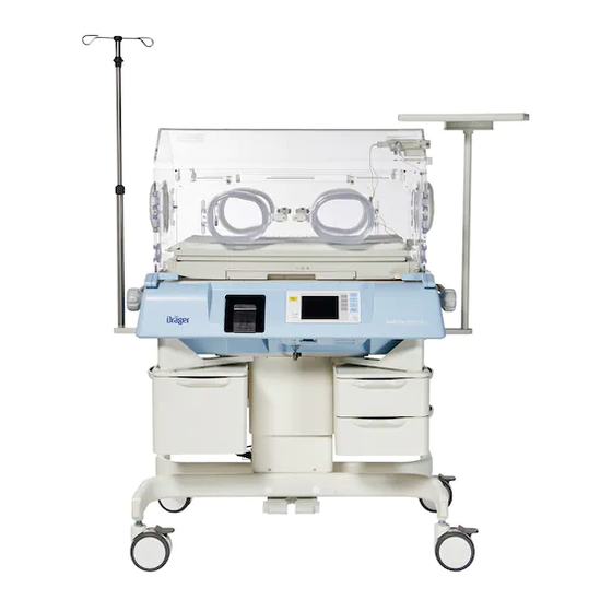
Castor wheels (with brakes) Hand port Drawers (optional) Access panel Incubator power cable receptacle Screen Water reservoir (optional) Front panel of controller Trendelenburg bed-tilt knob Serial port Monitor shelf (optional) Incubator on/off switch Instructions for use Isolette 8000 plus SW 5.n... -
Page 28: Rear View
Overview Rear view Incubator rating plate Oxygen inlet Height adjustment trolley rating plate Steering castor wheel Cable wrap Cylinder mount (optional) Air inlet filter Instructions for use Isolette 8000 plus SW 5.n... -
Page 29: Right Side View
Overview Right side view Sensor module Oval hand port (or optional iris port) Hood release knob Controller/sensor module interface connector Accessory rail/handle Hose grommets Instructions for use Isolette 8000 plus SW 5.n... -
Page 30: Left Side View
Overview Left side view Auxiliary power sockets Power cable receptacle Main on/off switch Fuse holder Collection bottle for condensation management (optional) Bracket for condensation management (optional) Hose for condensation management (optional) Instructions for use Isolette 8000 plus SW 5.n... -
Page 31: Sensor Module
Sensor Module 4.5.1 Top view Peripheral skin probe connector Central skin probe connector Alarm indicator Scale connector 4.5.2 Bottom view Controller interface cable Air, temperature, and humidity sensor housing Oxygen sensor housing Instructions for use Isolette 8000 plus SW 5.n... -
Page 32: External Devices
Overview External devices The Isolette 8000 plus has a serial port (A) that provides an isolated communication link between the incubator and an external device, such as, a central monitoring system or a patient monitor. The serial port has 2 communication options, serial data, or MEDIBUS.X. -
Page 33: Auxiliary Power Sockets
► Comply with the requirements of IEC 60601-1 when connecting other devices to auxiliary power sockets on the Isolette 8000 plus. ► Do not use auxiliary power sockets that are separate from the Isolette 8000 plus CAUTION Risk of damage to the device The total power of all equipment connected to the auxiliary power sockets on the trolley must be within the electrical requirements shown on the trolley. -
Page 34: Abbreviations
Relative humidity UMDNS Universal Medical Device Nomenclature System Symbols The following symbols appear on labels on the Isolette 8000 plus incubator, on the screen, and in these instructions for use. These standards apply as noted in the table. Symbol Meaning... - Page 35 (OIML scale only) Castor wheel locked Keypad lock Castor wheel unlocked Alarm Audio Paused/Reset key Electrostatic discharge Do not reuse (ESD) sensitive part Electromagnetic interfer- Maximum level indicator ence Communication port Half-full level indicator Instructions for use Isolette 8000 plus SW 5.n...
- Page 36 Do not spill Storage temperature limits Correct connection of con- Quantity densation management hose on the collection bot- Incorrect connection of condensation manage- ment hose on the collection bottle Phthalate present Use by Instructions for use Isolette 8000 plus SW 5.n...
-
Page 37: Technical Definitions
The amount by which the average temperatures at the mity center of the mattress quadrants, 10 cm (4 in) above the mattress surface, differ from the average incubator tem- perature at incubator temperature equilibrium. Instructions for use Isolette 8000 plus SW 5.n... - Page 38 Overview Term Definition Temperature variation The variation of the incubator temperature that will be (stability) observed over a one hour period after steady tempera- ture condition has been reached. Instructions for use Isolette 8000 plus SW 5.n...
-
Page 39: Operating Concept
Operating concept Front panel of controller The front panel of the Isolette 8000 plus controller is on the front of the incubator shell assembly. It consists of the following elements: A screen displaying all patient and system information in numeric and graphic form Variable-function keys (referred to as “buttons”... -
Page 40: Screen
Screen The actual screen display may differ in appearance or configuration. The basic Isolette 8000 plus screen can be toggled between display 1 and display 2. The displays differ in the selection of buttons available in the Temperature window. Both displays are divided into the following 4 windows: Temperature window - The temperature window displays the actual air and/or skin temperature and the set point of the controlling parameter. -
Page 41: Keys
If no alarms are present, the Audio Paused/Reset key enables a alarm silence. The Display Selection key enables the user to switch between displays that are not accessible via the currently displayed buttons. Instructions for use Isolette 8000 plus SW 5.n... -
Page 42: Buttons
Use the display selection key to switch between display 1 and display 2. 5.4.1 Display 1 buttons Air –selects the air temperature mode Skin–selects the skin temperature mode Humidity (optional)–selects the humidity display Oxygen (optional)–selects the oxygen display Instructions for use Isolette 8000 plus SW 5.n... - Page 43 Trend/Alarm window. >37°C Activates the temperature override mode (greater than 37.0 °C (98.6 °F)). ->0/T<- Available at the Weight display. When pressed, it provides zero setting and tare balancing. Instructions for use Isolette 8000 plus SW 5.n...
-
Page 44: Led Indicators
37 °C (98.6 °F) or higher. There is also a yellow LED on the sensor module that illuminates to indicate that an alarm is in progress (see Sensor Module on page 31). Instructions for use Isolette 8000 plus SW 5.n... -
Page 45: Thermomonitoring
(appears in place of Peripheral when Difference is selected). Skin temp Shows the central and peripheral skin temperature histories and the difference between them shaded in between their data lines. Trends are shown in graph format. Instructions for use Isolette 8000 plus SW 5.n... - Page 46 This page has been left blank intentionally. Instructions for use Isolette 8000 plus SW 5.n...
-
Page 47: Assembly And Preparation
To install the IV pole, utility shelf, and rail components, refer to their assembly instructions. WARNING Risk of death or serious injury The device could tip over. ► Strictly adhere to the weight and placement requirements for accessories and optional components. Instructions for use Isolette 8000 plus SW 5.n... - Page 48 ► Total load for the tray must not exceed 1.2 kg (2.6 lb). ► Total load for the swivel drawer large must not exceed 4.5 kg (10 lb). ► Total load for the swivel drawer small must not exceed 2.2 kg (5 lb). Instructions for use Isolette 8000 plus SW 5.n...
-
Page 49: Installing The Weighing System (Option)
► Total rail system weight should not exceed 13.6 kg (30 lb); 6.8 kg (15 lb) per side. For weight limitations for accessories and components for the Isolette 8000 plus, see Technical Data on page 167. Installing the weighing system (option) 6.4.1... - Page 50 1 Rotate the locking knobs, and open the front access panel of the incubator. 2 Remove the mattress from the incubator. 3 Orient the scale so that the scale cable is on the right-hand side of the incubator towards the sensor module assembly. Instructions for use Isolette 8000 plus SW 5.n...
- Page 51 9 Connect the scale cable to the weight connector on the sensor module assembly (see Sensor Module on page 31). WARNING Risk of death or serious injury Infant could become entangled with cables and be injured. ► Use cable management clips. Instructions for use Isolette 8000 plus SW 5.n...
-
Page 52: Installing The Humidification System (Option)
2 Ensure that the evaporator is installed in the evaporator chamber (B) at the rear of the reservoir. 3 Secure the lid by reinstalling it on the reservoir and pushing back the latch on top of the lid. Instructions for use Isolette 8000 plus SW 5.n... - Page 53 3 Connect the condensation management hose that protrudes from the underside of the incubator to the patient port (B) on the side of the collection bottle. 4 Secure the hose clamp (C). Instructions for use Isolette 8000 plus SW 5.n...
-
Page 54: Installing The Servo Oxygen Control System (Option)
4 If present, unplug the scale cable and any skin temperature probe cables from the sensor module. 5 Pull down the lock (A) on the sensor module (B) and slide the module out from the hood until it stops. Instructions for use Isolette 8000 plus SW 5.n... - Page 55 8 Screw each new sensor (E) into the sensor plate (F), and connect the cables (G). Either cable may be attached to either sensor. 9 Reinstall the plate with sensors into the sensor module, and reinstall the screws. Instructions for use Isolette 8000 plus SW 5.n...
- Page 56 (see Oxygen sensor calibration (option) on page 160). Note carefully the use of room air (21% oxygen) or pure oxygen, as dictated by the presence or absence of the 100% oxygen calibration fixture on the hood. Instructions for use Isolette 8000 plus SW 5.n...
-
Page 57: Installing The 100% Oxygen Calibration Fixture (Optional)
6 Ensure the proper positioning of the O-ring (A) on the 100% calibration fixture. The 100% calibration fixture is packaged with a small O-ring, which is coated with a lubricant. The O-ring could possibly become loose during shipping. Instructions for use Isolette 8000 plus SW 5.n... - Page 58 11 Select the 100% calibration level (see System configuration menu on page 113). ✓ Oxygen calibration fixture is set to 100% and the installation is complete. Instructions for use Isolette 8000 plus SW 5.n...
-
Page 59: Installing The Breathing Hose Holder (Accessory)
✓ When installed, the holder can be adjusted vertically and horizontally for convenient positioning of breathing hoses. When adjusting the breathing hose holder, make sure that it does not interfere with the scale (if installed) to allow for correct weight measurements. Instructions for use Isolette 8000 plus SW 5.n... - Page 60 This page has been left blank intentionally. Instructions for use Isolette 8000 plus SW 5.n...
-
Page 61: Getting Started
► Comply with the requirements of IEC 60601-1 when connecting other devices to auxiliary power sockets on the Isolette 8000 plus. ► Do not use auxiliary power sockets that are separate from the Isolette 8000 plus WARNING Risk of patient injury or device failure If the device loses its power source, the patient could be injured or the device damaged. - Page 62 (see System configuration menu on page 113). ✓ Incubator and options are set to the desired mode and configuration. Instructions for use Isolette 8000 plus SW 5.n...
-
Page 63: Functional Check Procedure
The incubator is powered on for at least 1 minute. 2 Check the Power Failure alarm: The incubator must be powered on for at least 1 minute before this test is performed. Instructions for use Isolette 8000 plus SW 5.n... - Page 64 6 Close the front or rear access panel, and rotate both latches until fully engaged. 7 Press the Audio Paused/Reset key. The alarm is silenced. 5 Check the Central Probe Missing alarm. Instructions for use Isolette 8000 plus SW 5.n...
- Page 65 Hood/shell functional check 1 Check the access panels: 1 Rotate the locking knobs, and open the front access panel. At the controller screen, the access panel open symbol ( ) appears. Instructions for use Isolette 8000 plus SW 5.n...
- Page 66 – Disconnect the weighing scale cable from the sensor module. – Close the access panel, and rotate both latches until they are fully engaged. 2 Slowly tilt the hood back until the hood locks in place (B). Instructions for use Isolette 8000 plus SW 5.n...
- Page 67 The iris port opens and closes as rotation is continued through 360 °. 4 Check the hand port latches and gaskets. 1 Press the latch (B) on each hand port. The door swings open. Instructions for use Isolette 8000 plus SW 5.n...
- Page 68 4 Repeat steps 1 through 3 for the rear access panel and rear inner double wall. 6 Check the bed elevators: 1 Rotate the right bed-tilt knob (A) counterclockwise until it stops. The bed is in the full “up” position (B). Instructions for use Isolette 8000 plus SW 5.n...
- Page 69 4 Carefully lean on the bed to ensure that it is properly supported and provides a firm infant platform. 5 Return the bed. 6 Close the front access panel, and rotate both locking knobs until they are fully engaged. Instructions for use Isolette 8000 plus SW 5.n...
- Page 70 1 Rotate the locking knobs, and open the front access panel. 2 Pivot the front access panel to the full open position (hanging straight down). 3 Slide out the X-ray tray (A). Instructions for use Isolette 8000 plus SW 5.n...
- Page 71 7 Close the front access panel, and rotate both latches until they are fully engaged. 11 Check the sensor module lock. 1 Pull down the sensor module lock (B). The sensor module slides in and out of the hood. Instructions for use Isolette 8000 plus SW 5.n...
- Page 72 2 To raise or lower the trolley to the maximum and minimum height, press and hold the foot pedal of the height adjustment trolley (A) at the front of the device. 3 Verify that the trolley operates smoothly and adjusts to the desired height. Instructions for use Isolette 8000 plus SW 5.n...
- Page 73 The mounting adapters lock when the toggle handle is switched to the left position (8 o’clock) (B). They unlock when the toggle handle is switched to the right position (4 o’clock) (C). Instructions for use Isolette 8000 plus SW 5.n...
- Page 74 6 Set the humidity set point to 50% (see Setting the humidity set point in manual mode on page 89). ✓ Within 30 minutes, the hygrometer and the humidity display both read 50% ± 6% relative humidity (RH). Instructions for use Isolette 8000 plus SW 5.n...
- Page 75 If the OIML/NAWI scale is moved to a different geographical location, the scale must be recalibrated. Also, the Isolette 8000 plus controller must be reconfigured, and the scale calibration label on the back of the incubator must be updated with new latitude and altitude values.
- Page 76 6 Remove the weight from the bed, and press the Home button. 7.2.9 Utility shelf (optional component) functional check 1 Ensure that the utility shelf and support arm are secure. 2 Ensure that the utility shelf rotates with the desired resistance. Instructions for use Isolette 8000 plus SW 5.n...
-
Page 77: Operation
► Take necessary measures to keep the incubator away from these drafts. The temperature of the warm air entering the patient compartment at the front and rear of the incubator is higher than the typical incubator air temperature. Instructions for use Isolette 8000 plus SW 5.n... - Page 78 To lower the set temperature in 0.1° decrements, press the Down Arrow key (B). 4 Press the Home button (C) and confirm the air set temperature setting. Device returns to display 1. 5 Press the Keypad Lock (D) key. ✓ Keypad is locked. Instructions for use Isolette 8000 plus SW 5.n...
- Page 79 To select the set point in skin temperature mode: 1 If necessary, unlock the keypad. If no keys are pressed within 15 seconds of making any selection, the screen automatically reverts to the previous display. Instructions for use Isolette 8000 plus SW 5.n...
- Page 80 0.1° decrements, press the Down Arrow key (C). 5 To confirm the skin set temperature setting, press the Home button (D). Device returns to display 1. 6 To lock the keypad, press the Keypad Lock key (E). Instructions for use Isolette 8000 plus SW 5.n...
- Page 81 Risk of injury or damage to the device Noncompliance may result in injury or damage to the device. ► Do not clean and reuse single-use components. ► Do not use single-use components or accessories if packaging is damaged. Instructions for use Isolette 8000 plus SW 5.n...
- Page 82 1 While operating in the skin temperature mode, insert a yellow skin probe into the central skin probe connector (A). 2 If monitoring 2 temperatures, insert a white skin probe into the peripheral skin probe connector (B). Instructions for use Isolette 8000 plus SW 5.n...
- Page 83 ► Monitor the patient core temperature with a separate calibrated thermometer. Failure to do so could result in patient injury. The skin temperature sensor is not a clinical thermometer. ► Check the patient core temperature regularly using an independent thermometer. Instructions for use Isolette 8000 plus SW 5.n...
- Page 84 ThermoPad cover over the probe wire approximately 3 cm (1 in) to 4 cm (1.5 in) from the tip of the probe. 4 If planning to use peripheral skin temperature probe, place the white probe on the infant at either hand or foot. Instructions for use Isolette 8000 plus SW 5.n...
-
Page 85: Setting The Humidity (Option)
Under certain environmental conditions, condensate may appear on the inner double walls of the hood. Condensate formation can be minimized or eliminated by lowering the relative humidity setting. Check the water level in the water reservoir twice per day. Instructions for use Isolette 8000 plus SW 5.n... - Page 86 The water level is visible through the front of the water reservoir. In addition, the minimum (A), half-full (B), and maximum (C) water marks on the reservoir latch can be used to assess the water level. Instructions for use Isolette 8000 plus SW 5.n...
- Page 87 ► Ensure that the cover on the filling inlet is closed. 8.2.2 Selecting the humidity mode 1 Pre-warm the incubator in air temperature mode to the temperature prescribed by the attending physician or according to Nursery Standing Orders. Incubator is warmed. Instructions for use Isolette 8000 plus SW 5.n...
- Page 88 The rotating wheel (D) indicates that a humidity mode is active. The actual RH% achievable inside the system depends on the incubator temperature set point and room conditions. 6 Press the Off button (E). ✓ Humidity mode is deactivated. Instructions for use Isolette 8000 plus SW 5.n...
-
Page 89: Setting The Servo Control Oxygen (Option)
If arterial oxygen levels cannot be maintained when the oxygen control setting is set to maximum, the attending physician should prescribe alternate means of oxygenation. Instructions for use Isolette 8000 plus SW 5.n... - Page 90 The rotating wheel (B) indicates that the oxygen mode is active. 6 If the message Cal Required is displayed, calibrate the oxygen control system (see Shutting down the Isolette 8000 plus properly on page 108). 7 Press the Off button (C).
- Page 91 To lower the set point within a range of 65% to 21%, press the Down Arrow key (E). 3 To acknowledge the oxygen control setting, press the Home button (F). Device returns to display 1. 4 Press the Keypad Lock key (G). ✓ Keypad is locked. Instructions for use Isolette 8000 plus SW 5.n...
-
Page 92: Using Manual Control Of Oxygen (Option)
30% to 50% 6 L/min 40% to 65% 9 L/min 45% to 75% 12 L/min 50% to 90% 15 L/min 60% to 100% Trending The actual screen display may differ in appearance or configuration. Instructions for use Isolette 8000 plus SW 5.n... - Page 93 6 To select one of the following Trend displays, press the Display button (C) repeatedly until the desired setting is shown: Air temp Skin temp Heater power % Oxygen (optional) Humidity (optional) Weight (optional) Instructions for use Isolette 8000 plus SW 5.n...
-
Page 94: Weighing- Scale Measurements (Option)
Trendelenburg position. 8.6.2 Standard scale measurements 8.6.2.1 Initial weigh To perform the initial weighing function: 1 If necessary, unlock the keypad. 2 At display 1, press the Display Selection. Display 2 appears. Instructions for use Isolette 8000 plus SW 5.n... - Page 95 The Weight Sample bar fills, and the weight of the infant is displayed in the Trend/Alarm window (D). 1.134 Kg 7 To enter the infant weight in the Trend/Alarm window, press the Store button (E). Instructions for use Isolette 8000 plus SW 5.n...
- Page 96 24-hour period. Subsequent trend data for the remaining 6 days represent the difference between the last stored weight, within a 24-hour period, and the baseline weight measurement. Instructions for use Isolette 8000 plus SW 5.n...
-
Page 97: Using Kangaroo Mode
4 minutes: – Low Air Temperature – Low Humidity – Low Oxygen % – Central Skin Temp Low – Peripheral Skin Temp Low – Skin Temp Diff High – Skin Temp Diff Low Instructions for use Isolette 8000 plus SW 5.n... - Page 98 Humidity parameter field Shows humidity status Oxygen parameter field Shows oxygen status Trend parameter field Shows trends Temperature parameter Shows temperature status field Alarm display Shows alarm messages, if applicable, replaces the Trend display Instructions for use Isolette 8000 plus SW 5.n...
- Page 99 However, the central skin temperature value does not affect the temperature in the patient compartment. 7 Close the hood or access panel. Ensure that the hoses and cables do not get caught or kinked. Instructions for use Isolette 8000 plus SW 5.n...
-
Page 100: Setting Up Alarm Limits And Display Units
- 1.5 °C (- 2.7 °F) to - 2.5 °C (- 4.5 °F) limit range Skin temperature deviation limit range 0.3 °C (0.5 °F) to 1.0 °C (1.8 °F) Oxygen deviation limit range 3% to 5% Instructions for use Isolette 8000 plus SW 5.n... - Page 101 The Temp/O2 setup screen appears. C / F 21.9 35.0 35.3 22.2 Setup Temp/O2 Air Temp Upper Deviation + Air Temp Lower Deviation - Skin Temp Deviation +/- Oxygen Deviation +/- Instructions for use Isolette 8000 plus SW 5.n...
- Page 102 Kangaroo mode skin temperature differ- 5.0 °C(9.0 °F) ence upper limit default Kangaroo mode skin temperature differ- ence lower limit default 1 Press the Kangaroo key (B). C / F 21.9 35.0 35.3 22.2 Instructions for use Isolette 8000 plus SW 5.n...
- Page 103 If the difference between the measured central skin temperature and the measured peripheral skin temperature is less than the temperature difference lower limit: – The screen shows an alarm message Skin Temp Diff Low. – An acoustic alarm signal begins. Instructions for use Isolette 8000 plus SW 5.n...
-
Page 104: Adjusting Height
► When operating the height adjustment trolley, always place one hand on the incubator for support to keep from losing your balance. The Isolette 8000 plus has 2 sets of foot pedals, one on the front of the device and one on the rear of the device. -
Page 105: Using The X-Ray Tray
10 Remove the X-ray cassette from the tray, and return the tray. 11 Close the access panel, and ensure that the locking knobs are fully engaged. 12 Replace any accessories that were previously removed. Instructions for use Isolette 8000 plus SW 5.n... -
Page 106: Using The Communication Interface
The Isolette 8000 plus supports serial data output and Dräger MEDIBUS.X communication protocol. MEDIBUS.X is a software protocol for data exported between Isolette 8000 plus and an external device by an RS-232 interface. (Examples are hemodynamic monitors, data management systems, or computers). - Page 107 8 See the instructions for use for the specific patient monitor for further setup and operation information. For the parts required to connect the Isolette 8000 plus infant incubator to the Dräger Infinity Delta or Delta XL monitors, see Optional components on page 182.
-
Page 108: Shutting Down The Isolette 8000 Plus Properly
3 Disconnect the incubator from the oxygen source. 4 Switch off the on/off switch on the incubator shell to power down the incubator. 5 Switch off the main On/Off switch on the stand. Instructions for use Isolette 8000 plus SW 5.n... -
Page 109: Alarms
An appropriate message appears in the Trend/Alarm window (A) An LED indicator illuminates (on the Audio Paused/Reset key (B) or on the sensor module) An acoustic alarm signal sounds Instructions for use Isolette 8000 plus SW 5.n... - Page 110 For a complete list of Isolette 8000 plus alarm messages, see Alarm – Cause – Remedy on page 115. Instructions for use Isolette 8000 plus SW 5.n...
-
Page 111: Alarm Priorities
Alarms Alarm priorities Isolette 8000 plus alarms are organized into one of 2 categories based on the urgency of the alarm: Color Priority of the alarm mes- Action required sage Yellow Caution Medium-priority Prompt action required to avert alarm risk. - Page 112 If there is a new alarm during the silence period, the device reacts as follows: – Acoustic alarm signal sounds. – The new alarm message is displayed. – The LED on the Audio Paused/Reset key (B) illuminates (depends on priority of the alarm). Instructions for use Isolette 8000 plus SW 5.n...
-
Page 113: Configuration
3657 m) (increments of 2000 ft) External interface Serial Data/MEDIBUS.X Serial Data Display Color Yellow/black / White/blue White/blue 1) For OIML devices, only kg units shall be displayed. 2) Used for 21% oxygen calibration offset Instructions for use Isolette 8000 plus SW 5.n... - Page 114 To display a system information screen, press the Diag Info button (F). To access more configuration menu items, press the Page 2 button (G). Press the Audio Paused/Reset key (A). ✓ System exits the system configuration menu. Instructions for use Isolette 8000 plus SW 5.n...
-
Page 115: Troubleshooting
11.1 Alarm – Cause – Remedy The Isolette 8000 plus displays alarm messages in the Trend/Alarm window. If two or more system alarms occur simultaneously, or one after the other, the alarm messages of the highest priority (i.e., Controller Failure alarms) are presented first. - Page 116 Verify proper positioning of the correct position for cali- the sensor module. If the bration or operation. alarm persists, switch off the (Alarm can be silenced for 5 minutes) incubator and remove it from service. Instructions for use Isolette 8000 plus SW 5.n...
- Page 117 MEDIBUS Comm. Error Communication has failed Check the cable and the after a successful communi- connection. cation. To acknowledge the alarm, press the Audio paused/Reset key. Contact DrägerService. Instructions for use Isolette 8000 plus SW 5.n...
- Page 118 15 minutes) > 38.0 °C when the tem- perature override mode is not active, or > 39.0 °C when the > 37 °C mode of operation is active. Switch off external heat sources. Instructions for use Isolette 8000 plus SW 5.n...
- Page 119 (for a maximum of 30 minutes)) The skin probe is not prop- Verify that the probe is cor- erly secured to skin (in skin rectly attached to the temperature mode only). patient. Instructions for use Isolette 8000 plus SW 5.n...
- Page 120 This message is displayed Replace the central skin in air temperature mode, temperature probe. kangaroo mode, or skin temperature mode, if: The temperature measured by the central skin tempera- ture probe is ≤ 16.9 °C. Instructions for use Isolette 8000 plus SW 5.n...
- Page 121 The skin probes are not Verify that the probes are properly secured to skin. correctly attached to the patient. Instructions for use Isolette 8000 plus SW 5.n...
- Page 122 Humidifier malfunction. Replace the humidifier. If the failure continues, switch off the incubator and remove it from service. Instructions for use Isolette 8000 plus SW 5.n...
- Page 123 4-minute pro- cedural silence) (this alarm is only available when servo oxygen control is activated.) A hand port or iris port is Close all hand ports and iris open. ports. Instructions for use Isolette 8000 plus SW 5.n...
-
Page 124: Problems/Alarm Conditions Without Alarm Messages
The power cable to the incubator Attach the power cable to the on the front of the device is incubator receptacle. unplugged. Instructions for use Isolette 8000 plus SW 5.n... - Page 125 Hose is connected to the wrong Ensure that the hose is con- port on the collection bottle. nected to the patient port on the side of the collection bottle. Instructions for use Isolette 8000 plus SW 5.n...
-
Page 126: System Prompt Messages
This message is displayed when Slide the sensor module out to the Cal button is pressed during the calibration position. oxygen calibration, but the sen- sor module is not pulled out into the calibration position. Instructions for use Isolette 8000 plus SW 5.n... - Page 127 Too Much Weight The controller determines that Remove excess weight. the weight placed on the scale is more than the scale measure- ment range. Instructions for use Isolette 8000 plus SW 5.n...
- Page 128 This message is displayed when Remove extra weight and retry an extra weight on the bed zeroing. If it fails again, remove exceeds 4000 g when zeroing scale from service. during infant weight. Instructions for use Isolette 8000 plus SW 5.n...
-
Page 129: Reprocessing
The most effective way to clean the device is to first disassemble the device. Then group the parts and assemblies in categories according to the method of cleaning required. 1 Switch off the device and all devices connected to it. 2 Disconnect the mains plugs. Instructions for use Isolette 8000 plus SW 5.n... - Page 130 6 Remove the cable from the clamps that hold it to the incubator. 7 Lift the scale (C) from the bed. 8 Remove the bed (D) and X-ray tray (inside bed). 9 Remove the T-bars (E). 10 Remove the upper cover (F). Instructions for use Isolette 8000 plus SW 5.n...
- Page 131 ► Avoid removing or touching the heater until the device has been switched off for at least 45 minutes. 3 When the device has cooled, remove the heater radiator (D). 4 Pull the impeller (E) off the motor shaft. Instructions for use Isolette 8000 plus SW 5.n...
- Page 132 Liquid in the collection bottle can contain patient fluids. ► Collection bottles and fluids should be handled according to hospital guidelines. When using high levels of humidity, Dräger recommends using the optional condensation management system. Instructions for use Isolette 8000 plus SW 5.n...
- Page 133 3 Remove the condensation management hose: A Turn the plug (D) at the bottom of the heater well 90 degrees counterclockwise. B Pull the hose/plug assembly out completely (E). 4 Discard the collection bottle and hose/plug assembly. Instructions for use Isolette 8000 plus SW 5.n...
- Page 134 3 Empty any water remaining in the reservoir. NOTICE Risk of damage to the device Sharp tools can cause injury or damage the device. ► Do not use sharp tools to remove the humidifier. Instructions for use Isolette 8000 plus SW 5.n...
- Page 135 3 If equipped with the optional iris ports on the side access panels, remove the disposable iris port sleeves from the retainer rings. 4 Wipe the retainer rings clean. 5 Discard disposable sleeves. Instructions for use Isolette 8000 plus SW 5.n...
-
Page 136: Information On Reprocessing
NOTICE Risk of damage to the device Harsh cleaning methods can damage equipment. ► Do not use harsh cleansers/detergents such as scouring pads or heavy-duty grease removers or solvents, such as acetone. Instructions for use Isolette 8000 plus SW 5.n... -
Page 137: Classifications For Reprocessing
Heater radiator Fan impeller Manifold Heater/impeller cover Duct cover Water reservoir assembly Humidifier Air inlet filter chamber Air inlet filter cover Rail and accessories Drawers Cylinder holder Utility shelf IV pole Mattress Instructions for use Isolette 8000 plus SW 5.n... -
Page 138: Reprocessing Procedures
They can be used in addition to the surface disinfectants listed in the section "Validated reprocessing procedures." The manufacturers of the surface disinfectants have verified at least the following spectra of activity: – Bactericidal Instructions for use Isolette 8000 plus SW 5.n... - Page 139 For disinfectant recommendations for the SoftBed mattress, consult their manufacturer instructions for use. 12.5.3 Surface disinfection with cleaning Refer to Disinfectants on page 138. Strictly observe the manufacturer’s instructions for using disinfectants. The composition of disinfectants may change. Instructions for use Isolette 8000 plus SW 5.n...
- Page 140 (on devices without the humidification system option). CAUTION Risk of injury or damage to the device On devices with the condensation management system option, the hose/plug assembly is disposable. ► Do not clean and reuse the hose/plug assembly. Instructions for use Isolette 8000 plus SW 5.n...
- Page 141 Do not spray cleaning solution directly onto the surface of the device. Refer to Disinfectants on page 138. 3 Be sure to clean all holes and indentations; then dry with a clean cloth or paper towel. Instructions for use Isolette 8000 plus SW 5.n...
- Page 142 Do not clean the air inlet filter (see Maintenance instructions on page 150). 1 Clean the filter chamber and its cover. Refer to Disinfectants on page 138. 2 Install a new air inlet filter. Instructions for use Isolette 8000 plus SW 5.n...
-
Page 143: After Reprocessing
Using older software versions can lead to incorrect operation of the humidification system leading to injury. ► The humidification system with the heater/impeller cover with duct cover must be used with software version 5.n or higher. Instructions for use Isolette 8000 plus SW 5.n... - Page 144 13 If equipped with the optional iris ports on the side access panels, install the new disposable or reusable iris port sleeves: A Install the smaller diameter elastic band of a new sleeve over the inner ring of the port housing. Instructions for use Isolette 8000 plus SW 5.n...
- Page 145 15 Install a hand port gasket on each hand port. Orient each gasket so that the 2 tabs on the gasket are on the hinge side of the door opening (B) and the single tab is on the latch side of the door opening (C). Instructions for use Isolette 8000 plus SW 5.n...
-
Page 146: Preparations Before Reuse
20 If necessary, reattach any accessories previously removed from the device. 12.7 Preparations before reuse 1 Assemble and prepare the device so that it is ready for use, see chapter Assembly and preparation 2 Check the operational readiness, see chapter Getting started. Instructions for use Isolette 8000 plus SW 5.n... -
Page 147: Service
► The housing may only be opened by those target groups that are assigned to that particular measure. 13.2 Overview This chapter describes the maintenance measures required to maintain the functional integrity of the medical device. Maintenance measures must be performed by the personnel responsible. Instructions for use Isolette 8000 plus SW 5.n... -
Page 148: Definition Of Service Terminology
– High temperature alarms 3 Inspect the following features: – Hand ports – Hood – Unauthorized probes or modifications to equipment – Incubator connection to height adjustment trolley – Movement of height adjustment trolley Instructions for use Isolette 8000 plus SW 5.n... -
Page 149: Maintenance
Every 2 years Exchange Service personnel Fan motor service kit Every 3 years Exchange Service personnel Fan in sensor module Every 3 years Exchange Service personnel pressure reducer Every 6 years Exchange Service personnel Instructions for use Isolette 8000 plus SW 5.n... - Page 150 6) Verification of the OIML/NAWI scale may also be required by, and performed by, local metro-logical author- ities. 13.5.1 Maintenance instructions Clean and disinfect device or components before each maintenance step, also before returning for repair. Instructions for use Isolette 8000 plus SW 5.n...
- Page 151 3 Install the air inlet filter cover, and tighten the 2 thumbscrews. 13.5.1.2 Fuse replacement 1 Disconnect the Isolette 8000 plus from electrical power. 2 Using a small screwdriver or similar tool, pry open the fuse holder cover (C) on the on/off switch module on the height adjustment trolley.
- Page 152 7 Remove the bed and X-ray tray. 8 Remove the T-bars. 9 Remove the upper cover. 10 Disconnect the condensation management hose (A) from the collection bottle located underneath the left side of the incubator. Instructions for use Isolette 8000 plus SW 5.n...
- Page 153 15 Insert the new hose/plug assembly fully into the drain opening at the bottom of the heater well. 16 Push the hose plug down until it is flush with the heater well floor. Turn the plug 90 degrees clockwise. Instructions for use Isolette 8000 plus SW 5.n...
- Page 154 Excess fluid in the collection bottle can lead to spillage and a safety hazard ► To avoid overflow, check the water level in the collection bottle every 8 hours. ► When the water level reaches the maximum mark on the bottle, replace the bottle. Instructions for use Isolette 8000 plus SW 5.n...
- Page 155 1 Remove oxygen servo assembly. 2 Remove O pressure reducer. 3 Replace O pressure reducer. 4 Set to 40 psi. 5 Install the oxygen servo assembly. 6 Perform the Functional check procedure on page 63. Instructions for use Isolette 8000 plus SW 5.n...
- Page 156 3 Partially remove the controller from the shell, disconnect all internal cables, and then fully remove the controller. 4 Open the shell assembly partially, and disconnect the corrugated hose. 5 Remove the upper shell. Instructions for use Isolette 8000 plus SW 5.n...
- Page 157 8 Install the humidity PCB (if present) into the new connector PCB (including the fan). 9 Install the new connector PCB (including the fan) into the sensor module. 10 Reassemble by reversing the order of disassembly. 11 Perform the functional check procedure (see page 63). Instructions for use Isolette 8000 plus SW 5.n...
- Page 158 5 Pull down the lock (A) on the sensor module (B) and slide the module out from the hood until it stops. 6 Pull out the clip (C) on the left side of the sensor module and remove the module from the hood completely. Instructions for use Isolette 8000 plus SW 5.n...
- Page 159 (G). Either cable may be attached to either sensor. 11 Reinstall the plate with sensors into the sensor module, and reinstall the screws. 12 Reinstall the sensor module in the hood, and position it in the normal (innermost) position. Instructions for use Isolette 8000 plus SW 5.n...
-
Page 160: Repair
If the sensor module cable is disconnected from the shell connector during operation, the message Cal Required is displayed. This message indicates that the servo oxygen control system must be calibrated. Instructions for use Isolette 8000 plus SW 5.n... - Page 161 8 If the message Cal Fail is displayed, refer to In case of calibration failure on page 162. 9 If the calibration procedure is unsuccessful a second time, refer the device to service personnel. Instructions for use Isolette 8000 plus SW 5.n...
- Page 162 13 If the calibration procedure is unsuccessful a second time, refer the device to service personnel. 13.7.1.3 In case of calibration failure These measures are independent troubleshooting measures that do not need to be performed in sequence. Instructions for use Isolette 8000 plus SW 5.n...
- Page 163 If the 5-kg weight is not placed on the center of the bed within 40 seconds after the 5-kg symbol is displayed, the Calibration Failed message is displayed. 8 Wait for the Weight Sample bar to fill and a weight reading of 5.000 kg to be displayed (B). Instructions for use Isolette 8000 plus SW 5.n...
- Page 164 13.7.2.2 OIML/NAWI scale adjustment (if installed) OIML/NAWI scales can only be adjusted by service personnel. Contact DrägerService for further information. OIML/NAWI scales can only be verified by representatives of the local authority. Instructions for use Isolette 8000 plus SW 5.n...
-
Page 165: Disposal
Dräger on the Internet at www.draeger.com. Use the Search function with the keyword "WEEE" to find the relevant information. If access to Dräger's website is not possible, contact the local Dräger organization. Instructions for use Isolette 8000 plus SW 5.n... - Page 166 This page has been left blank intentionally. Instructions for use Isolette 8000 plus SW 5.n...
-
Page 167: Technical Data
Ambient air pressure 110 kPa to 70 kPa Storage conditions Temperature -20°C (-4°F) to 60 °C (140 °F) Humidity 5% to 95% relative humidity, non-con- densing Ambient air pressure 110 kPa to 50 kPa Instructions for use Isolette 8000 plus SW 5.n... - Page 168 5 points at 10 cm (4 in) above the mat- tress Carbon Dioxide (CO ) level < 0.5% Set point data retention Power failures lasting <10 min Alarm sound level >65 dBa Instructions for use Isolette 8000 plus SW 5.n...
- Page 169 80% @ 20 °C (68 °F) to 40 °C (104 °F) Humidity display range 10% to 100% Humidity display resolution Maximum humidity levels >85% (incubator set temp at 39 °C, with at least 30% RH at ambient) Instructions for use Isolette 8000 plus SW 5.n...
- Page 170 10 g Weight display accuracy 10 g ≤ 4.0 kg Maximum tare weight Verification scale interval 10 g Scale level sensitivity 90 arc minute (1.5 degrees) Weight display update rate 1 second Instructions for use Isolette 8000 plus SW 5.n...
-
Page 171: Device Combinations
► Before operating the medical device, strictly comply with the instructions for use of all connected devices or device combinations. Instructions for use Isolette 8000 plus SW 5.n... -
Page 172: Emc Declaration
(for which CISPR 11 class B is normally required), this equipment might not offer adequate protection to radio-frequency communication services. The user might need to take mitigation measures, such as relocating or re- orienting the equipment. Instructions for use Isolette 8000 plus SW 5.n... - Page 173 To ensure that the functional integrity of this device is maintained, there must be a separation distance of at least 1.0 m (3.3 ft) between this device and wireless communication devices. Instructions for use Isolette 8000 plus SW 5.n...
- Page 174 This page has been left blank intentionally. Instructions for use Isolette 8000 plus SW 5.n...
-
Page 175: Principles Of Operation
16.2.1 Air circulation system The Isolette 8000 plus incubator uses a forced air circulation system to warm the infant. A controlled amount of room air, approximately 7 liters per minute (L/min), is drawn through the air inlet filter by the motor-driven impeller located in the shell. - Page 176 Instead, the incubator should be set up so that when "kangarooing" is concluded and the infant is returned to the incubator, the incubator is heated to the same temperature, and climate as when the infant was taken out of the incubator. Instructions for use Isolette 8000 plus SW 5.n...
- Page 177 2 temperature values and evaluating their difference. The Isolette 8000 plus trend display shows the trend histories of a maximum of 2 skin temperatures. The difference between central skin temperature and peripheral skin temperature, which is essential for Thermomonitoring, can be displayed continuously.
-
Page 178: Oxygen System
Principles of operation 16.3 Oxygen system The Isolette 8000 plus is equipped with either a servo oxygen control system or a manual oxygen control system. 16.3.1 Servo oxygen control system (option) When installed, the servo oxygen control system maintains oxygen concentration within the hood via a valve and an oxygen sensor module. - Page 179 The water enters the humidifier chamber at the back of the reservoir. The humidifier raises the temperature of the water to the boiling point, causing vaporization. No waterborne bacteria are introduced into the patient compartment by the vaporization process. Instructions for use Isolette 8000 plus SW 5.n...
-
Page 180: Condensation Management System (Option)
Condensation management system (option) Condensate formation can occur on the inside of the hood under certain environmental conditions. On Isolette 8000 plus incubators that are equipped with the condensation management system, excess water is routed to the heater well where it drains via the hose into the collection bottle. The condensation management system consists of a bottle and hose/plug assembly mounted on a bracket underneath the incubator. -
Page 181: Accessories
Description Part number Humidity Collection bottle, disposable, box of 20, 800 cc MU10918 Hose/plug assembly, condensation management, 20 MU21120 Miscellaneous Air inlet filter, replacement, 4 MU12504 Iris port sleeve, disposable, 100 MU03876 Instructions for use Isolette 8000 plus SW 5.n... -
Page 182: Optional Components
Starter package for Isolette, reusable cover and positioning aids MP01427 VarioLux EU MP00601 VarioLux US MP00602 VarioLux GB MP00603 VarioLux CHN MP00604 VarioLux BR MP00605 VarioLux AUS MP00606 VarioLux ZA MP00607 VarioLux JPN MP00608 Instructions for use Isolette 8000 plus SW 5.n... - Page 183 Buttons ......42 Cable......182 Instructions for use Isolette 8000 plus SW 5.n...
- Page 184 Drain plug ....125, 132, 150 Drawers..... 27, 171, 182 Instructions for use Isolette 8000 plus SW 5.n...
- Page 185 Indicator ....35, 39, 44, 110 Inspection ......148 Instructions for use Isolette 8000 plus SW 5.n...
- Page 186 OIML/NAWI ... . 34, 35, 96, 150, 164 Operating ......167 Instructions for use Isolette 8000 plus SW 5.n...
- Page 187 Warning ......34 Safety check ......148 Instructions for use Isolette 8000 plus SW 5.n...
- Page 188 Trolley ....27, 72, 137, 140 Troubleshooting ..... 115 Instructions for use Isolette 8000 plus SW 5.n...
- Page 189 X-ray tray......70 Yellow ..81, 82, 83, 99, 103, 110, 163, 181 Instructions for use Isolette 8000 plus SW 5.n...
- Page 190 This page has been left blank intentionally. Instructions for use Isolette 8000 plus SW 5.n...
- Page 191 Instructions for use Isolette 8000 plus SW 5.n...
- Page 192 These Instructions for use only apply to Isolette 8000 plus SW 5.n with the Serial No.: Without Serial No. filled in by Dräger, these Instructions for use are provided for general information only and do not apply to a specific medical device.
Need help?
Do you have a question about the Isolette 8000 plus and is the answer not in the manual?
Questions and answers