Table of Contents
Advertisement
Quick Links
Advertisement
Chapters
Table of Contents

Related Manuals for Agilent Technologies Nano Indenter G200


Summary of Contents for Agilent Technologies Nano Indenter G200
- Page 1 Agilent Technologies Nano Indenter G200 User’s Guide Agilent Technologies...
- Page 2 Notices © Agilent Technologies, Inc. 2013 Manual Part Number licensed as “Commercial computer soft- ware” as defined in DFAR 252.227-7014 No part of this manual may be reproduced G2A-13192-1 (June 1995), or as a “commercial item” as in any form or by any means (including defined in FAR 2.101(a) or as “Restricted...
-
Page 3: Specifications
Specifications Environmental Conditions Temperature (Operating): 5 to 40 °C Temperature (Non-operating): -40 to 70 °C Relative Humidity (Operating): 15 to 95 % non-condensing Altitude: 2000 m Agilent Nano Indenter G200 User’s Guide... -
Page 4: Disclaimers
This User’s Guide, as well as the hardware herein described, is licensed and can only be used in compliance with such terms and agreements as entered in by Agilent Technologies, Inc. Users of these products understand, except where permission is given by Agilent Technologies, Inc. -
Page 5: Contact Information
4330 W. Chandler Blvd., Chandler, Arizona 85226-4965 U.S.A. Tel: +1.480-756-5900 Fax: +1.480-756-5950 E-mail: NIO_SALES@agilent.com Web: www.agilent.com Customer Technical Support 1-800-844-6266 1-865-425-0566 Support Email: nanomechtech@agilent.com Distributors and Account Representatives Please visit our web site for up-to-date information: http://nano.tm.agilent.com/index.cgi?CONTENT_ID=253 Agilent Nano Indenter G200 User’s Guide... -
Page 6: Table Of Contents
Install the Sample Tray into the Indenter 2-18 Adjust the Height of the Samples 2-19 Methods and Batches in NanoSuite 2-27 First Batch Test 2-27 Second Batch Test 2-47 Third Batch Test 2-52 Congratulations! 2-52 Agilent Nano Indenter G200 User’s Guide... - Page 7 Tip-Change Tool 3-20 Tip-Retaining Nut 3-20 Vibration Isolation Table 3-21 4 NanoSuite Test Page Title Bar Menu Bar File Menu New Sample, Open Sample…, Save Sample, Save Sample As…, Exit Memo Properties… Print Print Preview Agilent Nano Indenter G200 User’s Guide...
- Page 8 Validate Method 4-27 Channel Diagnostics… 4-27 Preallocate… 4-27 Recalculate Sample 4-27 Recalculate Test 4-27 User Menu 4-28 Login… 4-28 Logout 4-28 Password… 4-28 View Profile… 4-28 Users… 4-30 Tip Menu 4-31 Select Tip 4-31 Agilent Nano Indenter G200 User’s Guide...
- Page 9 Channels Tab 4-68 Channels Right-Click Menu 4-68 Review Graph Setup 4-71 3D Tab 4-82 3D Right-Click Menu 4-83 Histogram Tab 4-92 Histogram Right-Click menu 4-94 Data Panel 4-99 Results Panel 4-103 Simulation Mode 4-105 Agilent Nano Indenter G200 User’s Guide...
- Page 10 Frame Stiffness and Area Function Calibration: Express Test 6-45 Frame Stiffness Calibration: ISO 14577 Method 6-51 Frame Stiffness Calibration: CSM Method 6-61 Cleaning the Tip 6-68 Best Method 6-68 Alternative Method 1 6-68 Alternative Method 2 6-68 Agilent Nano Indenter G200 User’s Guide...
- Page 11 Thermal Drift 7-31 Compensating for Deformation of the Load Frame 7-33 Compensating for the Force Exerted by the Support Springs 7-33 References 7-33 A Continuous Stiffness Measurement Quick Start Guide NanoSuite Reference Required Inputs Agilent Nano Indenter G200 User’s Guide...
- Page 12 Results D NanoSuite Explorer NanoSuite Explorer Overview Test Flow View Configuration View D-12 Method Error Log D-45 Insert Menu D-45 Tutorial D-46 Exercise 1 D-46 Exercise 2 D-48 Exercise 3 D-54 Exercise 4 D-55 Agilent Nano Indenter G200 User’s Guide...
- Page 13 Investigate an Unfamiliar NanoSuite Method G-10 Introduction G-10 Exercise G-10 H Express Test Getting Started Express Test Tip Calibration Express Test Methods Express Test for Thin Films-Batch Express Test to a Displacement Express Test to a Force H-10 Agilent Nano Indenter G200 User’s Guide...
- Page 14 Express Test Tip Calibration H-12 Express Test, Varied Force H-12 Agilent Nano Indenter G200 User’s Guide...
- Page 15 1-14 Contacting Agilent Technologies 1-14 Congratulations on the purchase of your Nano Indenter G200 system, the ultimate microprobe for testing mechanical properties. This system, equipped with NanoSuite software, provides the highest quality data and an ease of use unmatched by any other system. As the features and...
-
Page 16: Introduction
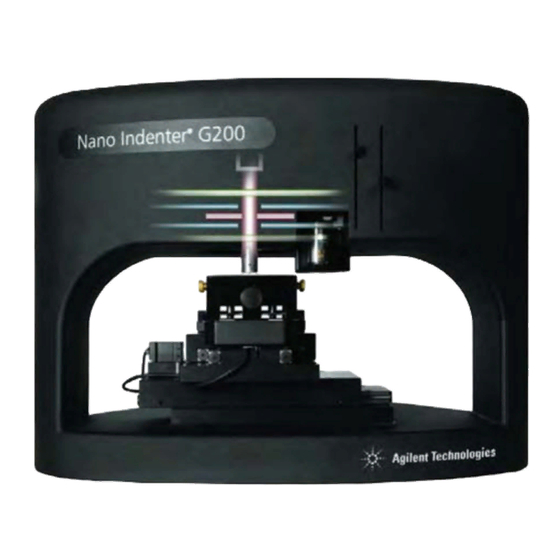
Introduction 1 Your G200 System The Nano Indenter G200, shown in Figure 1-1, is not an ordinary “black box” indenter. This platform for instrumented indentation testing is designed to deliver the highest expected performance levels as a base unit, yet it is also flexible to fit the most customized tests with optional configurations. - Page 17 Express Test: see Appendix H. • 350 °C heating stage • NanoVision For a complete list of the options specific to your machine, please refer to your order acknowledgement or the packing list provided with the shipment. Agilent Nano Indenter G200 User’s Guide 1-13...
-
Page 18: Agilent Technologies
Company History Agilent Technologies brings years of instrumentation experience to customers. In 1999, Agilent spun-off from Hewlett Packard. In 1983, Warren Oliver and John Pethica founded Nano Instruments, Inc. Warren Oliver, renowned in the field of Nanoindenting, remains involved with Agilent full-time. - Page 19 It should not be used to train new operators or modify or enhance software. A Note to Our Overseas Customers Overseas customers should contact their local Agilent Technologies representative or distributor for details concerning technical support. Training Agilent provides instrument and software training at the time of installation.
-
Page 20: Quick Start Guide
2-47 Third Batch Test 2-52 In this chapter, you will use your Nano Indenter G200 to perform several tests. This Quick Start Guide is intended to convey basic information on running the instrument and looking at data. It is not intended to convey all of the information that you need to get the most out of your instrument. -
Page 21: Hardware Overview
Quick Start Guide 2 Hardware Overview The Nano Indenter G200 is a complete, turnkey system consisting of the major components shown in Figure 2-1. Figure 2-1 Nano Indenter G200 Due to the extreme sensitivity of the system, environmental isolation is provided through a combination of the minus k vibration isolation table, and the thermal/sound insulated vibration isolation cabinet. -
Page 22: Facility And Instrument Dimensions
Nano Indenter G200 will sit. The Workspace PC Monitor/keyboard and Sample Preparation tables are not included in the purchase of an Nano Indenter G200. We recommend having a separate and dedicated work area for sample preparation so that cutting, mounting and adhering samples may be done away from the operating area of the machine. - Page 23 Quick Start Guide 2 Schematic diagrams indicating the width, depth and height of the G200 cabinet are shown in Figure 2-3. Figure 2-3 Schematics of G200 Cabinet Dimensions Agilent Nano Indenter G200 User’s Guide...
-
Page 24: Specifications
Quick Start Guide 2 Specifications The specifications for the Nano Indenter G200 are summarized in the following table: Standard Indentation Head Assembly Displacement Resolution < 0.01 nm Total Indenter Travel 1.5 mm Maximum Indentation Depth > 500 µm Load Application... -
Page 25: Software Interface Overview
The initial window in NanoSuite displays the Test page. Some common terms related to this initial view are shown in Figure 2-4. Figure 2-4 NanoSuite startup screen NanoSuite is described in more detail in Chapter 4, "NanoSuite". Agilent Nano Indenter G200 User’s Guide... - Page 26 For example, a batch may specify the following: Beginning at 2:00 a.m., the procedure described by method A should be performed ten times on each of two samples. Online Help An online Help system can be accessed from the File Menu. Agilent Nano Indenter G200 User’s Guide...
-
Page 27: Getting Started
Figure 2-5 Power switch for controller If NanoVision is installed, turn on all three power switches (OFL1, OFL2, and OFL3) for the PI Piezo Controller, as shown in Figure 2-6. Figure 2-6 Power switches for PI Piezo Controller Agilent Nano Indenter G200 User’s Guide... - Page 28 Turn on the Nano Indenter computer by momentarily pushing the On/Off button shown in Figure 2-8. Figure 2-8 G200 computer power button Remove the locking pins. Refer to Chapter 3, "Instrument Reference" for more information on removing the pins. Agilent Nano Indenter G200 User’s Guide...
-
Page 29: Launch Nanosuite
Figure 2-9 NanoSuite User Login dialog box In the Open Method dialog box, select XP > G-Series Load, Disp, and Time from the filename drop-down list, as shown in Figure 2-10 on page 2-11. Agilent Nano Indenter G200 User’s Guide 2-10... -
Page 30: Prepare A Sample For Testing
Finally, the indenter shall be withdrawn from the sample at arate that is twice as fast as the loading rate. Prepare a Sample for Testing Before you test a sample, you must prepare it by mounting it on a sample disk. Agilent Nano Indenter G200 User’s Guide 2-11... - Page 31 When the disk is warm, spread a small amount of crystalbond onto the surface of the disk, as shown in Figure 2-12. Figure 2-12Spreading crystalbond onto the surface of a sample disk Agilent Nano Indenter G200 User’s Guide 2-12...
- Page 32 For samples that are sensitive to heat, follow these steps: Locate a sample disk and place it on a heating element. Turn the heating element on medium-low heat and wait for the disk to heat for about 5 minutes. Agilent Nano Indenter G200 User’s Guide 2-13...
- Page 33 Turn the heating element off. Mix a small amount of five-minute epoxy. Using a wooden stick, place a small amount of epoxy on the slide, as shown in Figure 2-16. Figure 2-16Placing epoxy on the slide Agilent Nano Indenter G200 User’s Guide 2-14...
- Page 34 You can leave the remaining crystalbond on the sample disk for the next sample. Agilent Nano Indenter G200 User’s Guide 2-15...
-
Page 35: Install The Sample Disk Into The Sample Tray
Unscrew the brass thumbscrew next to the rear left sample disk hole about 1/4 of a turn (or enough to enable the disk to easily fit into the hole), as shown in Figure 2-19 on page 2-17. Agilent Nano Indenter G200 User’s Guide 2-16... - Page 36 Figure 2-20Sample flush with sample tray surface Turn the thumbscrew just enough to secure the disk in the hole but not so tight that the disk cannot travel vertically in the sample tray. Agilent Nano Indenter G200 User’s Guide 2-17...
-
Page 37: Install The Sample Tray Into The Indenter
Figure 2-21Adjust sample tray locking screw Slide the sample tray between the rails at the top of the motion system all the way to the end stop, as shown in Figure 2-22 page 2-19. Agilent Nano Indenter G200 User’s Guide 2-18... -
Page 38: Adjust The Height Of The Samples
The following procedure assumes that the height of the sample in the center of the sample tray has not been changed. Adjusting the height of the center sample requires Agilent technical support. Agilent Nano Indenter G200 User’s Guide 2-19... - Page 39 2-21) all the way to the brightest setting. If the system is idle for a while, the light bulb icon in the brightness control will dim and deactivate. To activate the control, click on it. Agilent Nano Indenter G200 User’s Guide 2-20...
- Page 40 Figure 2-25Select Test tab in NanoSuite In the handset area in the left panel, right-click and select Nano HandSet from the resulting pop-up menu, as shown in Figure 2-26. Figure 2-26Select Nano Handset from right-click meu Agilent Nano Indenter G200 User’s Guide 2-21...
- Page 41 Figure 2-28Select Move to Target from right-click menu Visually confirm that the microscope is over the center sample disk in the sample tray. The microscope does not have to be directly over the sample at this point. Agilent Nano Indenter G200 User’s Guide 2-22...
- Page 42 Lower the right aperture lever until the image becomes gray, to an average medium brightness. As shown in Figure 2-30 on page 2-24, use the microscope brightness control and coarse/fine focus controls to lighten the image and bring it into focus. Agilent Nano Indenter G200 User’s Guide 2-23...
- Page 43 Figure 2-31 on page 2-25 shows the thumbwheel, which is not visible from the front of the instrument. To access the thumbwheel, you will have to reach behind the sample tray. Agilent Nano Indenter G200 User’s Guide 2-24...
- Page 44 Right-click anywhere on the schematic map and select Nano Video Handset from the resulting pop-up menu. The image will probably be out of focus at this point. Agilent Nano Indenter G200 User’s Guide 2-25...
- Page 45 Securely lock the sample into the sample tray by fully tightening the brass thumbscrew next to the rear left sample disk hole. Repeat this procedure for other samples, going clockwise in the sample tray. Agilent Nano Indenter G200 User’s Guide 2-26...
-
Page 46: Methods And Batches In Nanosuite
From the Test page, click on the Batch Mode icon, shown in Figure 2-34. Figure 2-34Batch Mode icon in NanoSuite This will open the Batch Configuration window. Click New Batch in the Batch Configuration window as indicated in Figure 2-35. Agilent Nano Indenter G200 User’s Guide 2-27... - Page 47 Figure 2-35New Batch button in Batch Configuration window Select the location to store files as shown in Figure 2-36 page 2-29: You can leave as the default location or Click Add to define a new storage location. Agilent Nano Indenter G200 User’s Guide 2-28...
- Page 48 (which you will be doing). Many people find the last option useful, especially if the instrument sits in a laboratory that is noisy during the day but relatively quiet at night. You will not use this option right now. Click the Next Step button. Agilent Nano Indenter G200 User’s Guide 2-29...
- Page 49 Hardness, Modulus, Tip Cal, Load Control.msm as shown in Figure 2-37 Click the Next Step button. Edit the settings to find the surface and for drift to match those shown in Figure 2-38 on page 2-31. Agilent Nano Indenter G200 User’s Guide 2-30...
- Page 50 The lower the value, the longer the instrument will wait before initiating testing on a sample. The last value, Maximum Thermal Drift Time, sets the maximum time allowed to meet drift conditions set by Allowable Drift Rate. Agilent Nano Indenter G200 User’s Guide 2-31...
- Page 51 Stiffness Criteria sets the criteria that the indenter uses to decide whether it has contacted the test surface. A lower value causes more sensitive surface detection but increases the likelihood of false detection (and vice versa). Agilent Nano Indenter G200 User’s Guide 2-32...
- Page 52 Click the Next Step button. On the resulting video image, right-click anywhere in the handset area and select Nano HandSet from the resulting pop-up menu, as shown in Figure 2-41. Figure 2-41Select Nano HandSet from right-click menu Agilent Nano Indenter G200 User’s Guide 2-33...
- Page 53 The X/Y positioning table should then move to the proper location under the microscope and the red cone on the schematic map should move toward the target. Once the cone reaches the target, it turns green. Agilent Nano Indenter G200 User’s Guide 2-34...
- Page 54 Figure 2-45Select Nano Video Handset from right-click menu As shown in Figure 2-46 on page 2-36, use the microscope brightness control and coarse/fine focus controls to lighten the image and bring it into focus. Agilent Nano Indenter G200 User’s Guide 2-35...
- Page 55 To move the viewing area, place the cursor over the red crosshairs in the center of the video image, click, and slowly drag the cursor in the direction of the area you want to view. Agilent Nano Indenter G200 User’s Guide 2-36...
- Page 56 2 x 2 array with sequential tests 50 microns apart. Type the values shown in Figure 2-49 to create the array. Click OK. Figure 2-49Dialog box to define a test array Agilent Nano Indenter G200 User’s Guide 2-37...
- Page 57 Figure 2-50Batch Setup dialog box In the Batch Configuration dialog box (Figure 2-51), click Save Batch. Figure 2-51Save Batch, outlined in red, in the Batch Configuration dialog box This will open the Save Batch File dialog box. Agilent Nano Indenter G200 User’s Guide 2-38...
- Page 58 This action saves all the specifications for the batch so that you can NOT E recall and use the batch again later. In the Batch Configuration dialog box, click the Run Batch button, circled in Figure 2-53 on page 2-40, to begin the test. Agilent Nano Indenter G200 User’s Guide 2-39...
- Page 59 In the Review the first test location of Sample dialog box, as shown Figure 2-54 on page 2-41, verify that the microscope is in the correct location and then click OK to continue. Agilent Nano Indenter G200 User’s Guide 2-40...
- Page 60 (as shown in Figure 2-56 on page 2-42), and the text below the real-time graph. The real-time graph displays data as the test is running. It should take about ten minutes to complete the batch. Agilent Nano Indenter G200 User’s Guide 2-41...
- Page 61 Figure 2-57. If you are using a DCM, residual impressions may not be visible. Figure 2-57Residual indentation impressions Agilent Nano Indenter G200 User’s Guide 2-42...
- Page 62 In the Legend panel, select the 1 check box next to the first test (as shown in Figure 2-60 on page 2-44) so that the Review Graph will display only results from that test. Agilent Nano Indenter G200 User’s Guide 2-43...
- Page 63 The approximate depth of the residual impression left by this test is the intersection of the unloading (right-most) curve and the X axis. In the example shown, the depth of the residual impression is 1050 nm. Figure 2-61Load-Displacement curve from first test Agilent Nano Indenter G200 User’s Guide 2-44...
- Page 64 Figure 2-63. Figure 2-63Select Reset from right-click menu Right-click anywhere on the graph and select X-Axis Channel > Time (s) from the resulting pop-up menu, as shown in Figure 2-64 on page 2-46. Agilent Nano Indenter G200 User’s Guide 2-45...
- Page 65 You can verify that 1) loading took place in 25 seconds, 2) there was a 10-second dwell at peak load, and 3) the unloading rate was twice as fast as the loading rate. Figure 2-65Load vs Time Agilent Nano Indenter G200 User’s Guide 2-46...
-
Page 66: Second Batch Test
(click on one of the circles). Right-click on the marked circle and select Move to Target from the resulting pop-up menu. Right-click anywhere on the schematic map and select Nano Video Handset from the resulting pop-up menu. Agilent Nano Indenter G200 User’s Guide 2-47... - Page 67 Right-click on the Review Graph and select X-Axis Channel > Load On Sample (mN) from the resulting pop-up menu, as shown Figure 2-67 on page 2-49. Now the Review Graph displays the sample information as a function of load rather than displacement. Agilent Nano Indenter G200 User’s Guide 2-48...
- Page 68 Right-click on the Review Graph and select Y-Axis Channel > Hardness (GPa) from the resulting pop-up menu, as shown in Figure 2-68. Figure 2-68Set Y axis to Hardness Now the Review Graph displays hardness as a function of load. Agilent Nano Indenter G200 User’s Guide 2-49...
- Page 69 (****) in the first row in the results table. When a test fails, a warning message is issued to describe the reason for the failure as shown in Figure 2-70. Figure 2-70Test failure warning message Agilent Nano Indenter G200 User’s Guide 2-50...
-
Page 70: Results A
Calculation Inputs Table: This table displays important inputs that were used in the calculations. • Test Inputs Table: This table displays important inputs that were used to determine how the test was performed. Agilent Nano Indenter G200 User’s Guide 2-51... -
Page 71: Third Batch Test
Use the default batch and default method as we did in the second part of the tutorial. • Reload and use a saved batch, as we did in the third part of the tutorial. Agilent Nano Indenter G200 User’s Guide 2-52... - Page 72 Standard Reference Materials 3-19 Temperature Probe 3-19 Tip-Change Tool 3-20 Tip-Retaining Nut 3-20 Vibration Isolation Table 3-21 This chapter details the configuration of the hardware and accessories that makes up the Nano Indenter G200. Items are arranged alphabetically. Agilent Technologies...
-
Page 73: Instrument Reference
Adjustments in contrast will be more evident with higher-power objectives. The right aperture lever adjusts the amount of light picked up by the camera. Figure3- 2 Aperture levers on G200 Agilent Nano Indenter G200 User’s Guide... -
Page 74: Computer/Central Processing Unit (Cpu)
Computer/Central Processing Unit (CPU) The CPU provided with the Nano Indenter G200 serves as the host computer for the NanoSuite control software. All collected data are stored on the hard drive of your G200 computer. Electronic cards integrated into your computer manage the communication between the software and the external electronics. -
Page 75: Csm Controller
The CSM option is available for both the Nano Indenter G200 and Nano Indenter DCM instruments. The theory for CSM is discussed further in Appendix A, "Continuous Stiffness Measurement". -
Page 76: Dynamic Contact Module Ii
Gantry Assembly As shown in Figure 3- 7 on page 3-6, the Nano Indenter G200 gantry is used to support the indentation system, optics system, and motion system, as well as optional hardware. The gantry is manufactured to be extremely rigid, providing the system with a very high load frame stiffness (LFS). -
Page 77: Head Assembly
8, contains the actuator and sensors that make up the critical measurement portion of your G200. The head assembly is sometimes called the NMAT, which stands for nano-mechanical actuator and transducer. Figure3- 8 Head Assembly Agilent Nano Indenter G200 User’s Guide... -
Page 78: High Load Mechanism
Instrument Reference 3 The indenter head is the heart of the Nano Indenter G200. All of the other subsystems can be considered support systems for the indenter head. While the body of the indenter head is enclosed within the gantry, the indenter tip is exposed during operation of the instrument or when no power is supplied to the indenter’s loading system (but only if the... -
Page 79: Indenter
The closed (and sealed) cabinet provides a stable air mass in which sudden temperature changes are minimized. The foam lining on the interior of the cabinet absorbs acoustic energy and decreases the transmission of such excitation to the instrument. The fixed cable ports Agilent Nano Indenter G200 User’s Guide... - Page 80 Instrument Reference 3 provide a degree of decoupling of vibration transmission through the electronic and optical cables. Finally, the cabinet serves as a support for Vibration Isolation Table. Figure3- 11G200 Isolation Cabinet Agilent Nano Indenter G200 User’s Guide...
-
Page 81: Lateral Force Measurement
Figure3- 12Lateral Force Measurement probes for LFM option Locking Pins The locking pins, shown in Figure 3- 13, fix the indenter shaft so that the head is not damaged during a tip change or other contact with the diamond. Agilent Nano Indenter G200 User’s Guide 3-10... - Page 82 When not in use, the locking pins should be stored in the Tip-Change Tool, shown in Figure 3- Figure3- 14Tip-change tool with (left) and without (right) locking pins See also Changing the Indenter Chapter 6, "Commonly Used Procedures". Agilent Nano Indenter G200 User’s Guide 3-11...
-
Page 83: Microscope
The motors, gearboxes, and encoder that interface with the table are mounted on the gantry. These components should only be accessed by Agilent support technicians. Figure3- 15Positioning tables of the G200 Motion System Agilent Nano Indenter G200 User’s Guide 3-12... - Page 84 Figure 3- Click the Park Head button, as shown on the right in Figure 3- Figure3- 16System menu (left) and Displacement Control Panel dialog box (right) with Park Head button outlined in red Agilent Nano Indenter G200 User’s Guide 3-13...
-
Page 85: Mounting Specimens
Figure3- 1710 X and 40 X objectives included with the G200 Objective lenses for the Nano Indenter G200 optics system are mounted on precision slides so that they can be interchanged easily. To insert an objective, grasp the objective and slide it into the mounting rails on the microscope until it snaps into place. -
Page 86: Sample Disks
Sample Disks The sample disks fit within the Sample Tray and are used to hold samples. Figure 3- 19 shows a sample disk with a sample mounted on it. Figure3- 19G200 sample disk Agilent Nano Indenter G200 User’s Guide 3-15... -
Page 87: Sample Mount System
Tray, shown in Figure 3- Figure3- 20G200 Sample Mount System Sample Tray The sample tray, provided with your G200, holds up to five sample disks as shown in Figure 3- 21 on page 3-17. Agilent Nano Indenter G200 User’s Guide 3-16... -
Page 88: Single-Crystal Aluminum Sample
22), all of which is embedded in an epoxy puck. The puck is 1.25 inches in diameter and 1 inch in height. The primary use of this sample is in the "Microscope to Indenter Calibration" on page 4-55. The Agilent Nano Indenter G200 User’s Guide 3-17... -
Page 89: Specimen
Agilent service representative. See also "Microscope to Indenter Calibration" on page 149. Specimen Specimen refers to the material to be tested. See Crystalbond Hot Melt Sample Mount System. Agilent Nano Indenter G200 User’s Guide 3-18... -
Page 90: Standard Reference Materials
Figure3- 23Standard Reference Material with calibration certification (left) and serial number marker (right) Temperature Probe The test methods that comply with ISO 14577 acquire data from the temperature probe inside the G200 cabinet, as shown in Figure 3- Agilent Nano Indenter G200 User’s Guide 3-19... -
Page 91: Tip-Change Tool
Figure3- 25Tip-change tool Indenter Tip-Retaining Nut. Also see Changing the Indenter Chapter 6, "Commonly Used Procedures". Tip-Retaining Nut Shown in Figure 3- 26, the tip-retaining nut is used to attach the tip to Indenter shaft. Agilent Nano Indenter G200 User’s Guide 3-20... -
Page 92: Vibration Isolation Table
For adjusting the vibration isolation table, refer to Adjusting the Vibration Isolation Table Chapter 6, "Commonly Used Procedures". Figure3- 27G200 Vibration isolation table Agilent Nano Indenter G200 User’s Guide 3-21... -
Page 93: Nanosuite
Agilent Nano Indenter G200 User’s Guide NanoSuite Test Page File Menu Method Menu 4-11 Edit Menu 4-13 View Menu 4-14 Test Menu 4-18 Configure Menu 4-19 Tools Menu 4-26 User Menu 4-28 Tip Menu 4-31 Export Menu 4-34 Mode Menu... -
Page 94: Test Page
The features of NanoSuite are described here starting from the top of the NanoSuite window and proceeding downward. Thus the menus listed on the menu bar will be detailed first, followed by the panels in the different interfaces. Agilent Nano Indenter G200 User’s Guide... -
Page 95: Title Bar
Alt + F keys on your keyboard. Note that unavailable menu items are grayed out. The following menus are available in NanoSuite: File Menu Method Menu Edit Menu View Menu Test Menu Configure Menu Tools Menu User Menu Tip Menu Agilent Nano Indenter G200 User’s Guide... - Page 96 NanoSuite 4 Export Menu Mode Menu System Menu Help Menu Agilent Nano Indenter G200 User’s Guide...
-
Page 97: New Sample, Open Sample
Figure 4-3. Type in your note and click the OK button to attach the note to the currently open sample. To retrieve a previously recorded memo, simply select Memo… from the File menu. Agilent Nano Indenter G200 User’s Guide... -
Page 98: Properties
The Print command is used to print tests and samples as shown in Figure 4-4 on page 4-6. For printing batches, use the Batch Print… command and then select the files to be used in the batch printing. Figure 4-4 Print command from File menu Agilent Nano Indenter G200 User’s Guide... -
Page 99: Print Preview
Selecting Method from the Email submenu sends the test method via email, and selecting Sample sends the test data as shown in Figure 4-6 on page 4-8. Figure 4-6 Email command Agilent Nano Indenter G200 User’s Guide... -
Page 100: Export, Export Preview, And Batch Export
Further details on the use of the Import… command are presented in Appendix D,“NanoSuite Explorer.” After selecting Import...> From NanoSuite Sample..., the Import from NanoSuite Sample dialog box in Figure 4-8 on page 4-9 will appear. Agilent Nano Indenter G200 User’s Guide... - Page 101 NanoSuite 4 Figure 4-8 Import from NanoSuite Sample dialog box Choose a sample from the Select Sample drop-down menu as shown in Figure 4-9 on page 4-10. Agilent Nano Indenter G200 User’s Guide...
- Page 102 Clicking the OK button imports the selected tests into the resident sample. These data can now be treated like any other data in that sample. Agilent Nano Indenter G200 User’s Guide 4-10...
-
Page 103: Method Menu
This command is used to compress methods for storage and transmission. Selecting Pack... or Unpack..from the submenu starts a wizard that will guide you through the packaging process. Figure 4-11Method Packaging menu Agilent Nano Indenter G200 User’s Guide 4-11... -
Page 104: Edit Method
Figure 4-12Print Method command Print Preview Method This command (Figure 4-13) is used to preview the printed version of the method. The method will automatically appear in Windows Notepad. Figure 4-13Print Preview Method command Agilent Nano Indenter G200 User’s Guide 4-12... -
Page 105: Edit Menu
NanoSuite 4 Edit Menu This menu will appear on the Define Page only. The Cut, Copy, Paste, and Delete commands perform the same functions in NanoSuite as in other Windows applications. Figure 4-14Edit menu Agilent Nano Indenter G200 User’s Guide 4-13... -
Page 106: View Menu
Review page. Also, recently saved configurations for the Review page are listed in the bottom section of the View menu for convenient access. Agilent Nano Indenter G200 User’s Guide 4-14... -
Page 107: Save Current Review Page Configuration
Select Delete a Saved Review Page Configuration from the View menu, then Select the name of configuration to delete in the Delete Review page configuration dialog box shown in Figure 4-17 on page 4-16, then Click Delete to delete the configuration. Agilent Nano Indenter G200 User’s Guide 4-15... -
Page 108: Load A Saved Review Page Configuration
Locate the name of the page configuration that you want to load in the Load Review page configuration dialog box shown in Figure 4-18 on page 4-17, then Click the Load button to load the configuration. Agilent Nano Indenter G200 User’s Guide 4-16... - Page 109 NanoSuite 4 Figure 4-18Load Review page configuration dialog box Agilent Nano Indenter G200 User’s Guide 4-17...
-
Page 110: Test Menu
A test is divided into segments. You can use this command to skip the current segment and begin the next segment. Run Post-Sample Selecting this command executes instructions that are defined to run after all testing on a particular sample is complete. Agilent Nano Indenter G200 User’s Guide 4-18... -
Page 111: Configure Menu
Click the OK button when you are satisfied with the configuration. To revert back to a previous meter configuration, select Restore Screen NOT E to Method Saved Configuration from the View Menu. Agilent Nano Indenter G200 User’s Guide 4-19... - Page 112 To change the order in which the meters appear on your screen, select a meter and use the Up and Down arrows next to the Meters to Display list to promote or demote a meter within the list. Agilent Nano Indenter G200 User’s Guide 4-20...
-
Page 113: Statistics
To complete the workspace change, you will have to close and restart NanoSuite. A series of prompts will guide you through the process. For more information about switching between heads, see the “Quick Start Guide” of Appendix B. Agilent Nano Indenter G200 User’s Guide 4-21... -
Page 114: Toolbar
The Separator is used to add lines to keep icon classes categorized. The toolbar may be customized with a number of available buttons via the Customize Toolbar dialog Agilent Nano Indenter G200 User’s Guide 4-22... -
Page 115: Review Graph
If you are configuring the review graph and want changes to be applied NOT E to a Real-Time Graph…, then click the Styles tab in the Review Graph Setup dialog box and click Copy Changes to Real Time Graph. Agilent Nano Indenter G200 User’s Guide 4-23... -
Page 116: Real-Time Graph
Real-Time Graph Setup dialog box shown in Figure 4-27 on page 4-25. You can change the scaling, appearance, styles, and the number of displayed curves of a real-time graph. Agilent Nano Indenter G200 User’s Guide 4-24... - Page 117 NanoSuite 4 Figure 4-27Real-Time Graph Setup dialog box Agilent Nano Indenter G200 User’s Guide 4-25...
-
Page 118: Tools Menu
This command should only be used if you have purchased a calibration kit and are familiar with its use or when required during diagnostics and troubleshooting with a certified Agilent technician. This command may be grayed out if the calibration kit is not installed. Agilent Nano Indenter G200 User’s Guide 4-26... -
Page 119: Set Full Scale Load Range
Recalculate Test This command causes NanoSuite to recalculate the data for the current test, incorporating any changes that you have made to the analysis. Agilent Nano Indenter G200 User’s Guide 4-27... -
Page 120: User Menu
Figure 4-31 on page 4-29. The user can view his or her current settings but cannot change anything. Information accessed through the Directories and Properties tabs is read-only as well. Agilent Nano Indenter G200 User’s Guide 4-28... - Page 121 NanoSuite 4 Figure 4-31User Configuration dialog box Agilent Nano Indenter G200 User’s Guide 4-29...
-
Page 122: Users
This command enables you to create and edit user names, passwords, privilege levels, and properties via the Users List dialog box shown in Figure 4-32. Refer to the online Help via the Help button for more information. Figure 4-32Users List dialog box Agilent Nano Indenter G200 User’s Guide 4-30... -
Page 123: Tip Menu
Click OK to open a confirmation box. Click OK to continue with your selection. NanoSuite will re-analyze the data for the current sample using the new tip parameters. Figure 4-34Select Tip dialog box Agilent Nano Indenter G200 User’s Guide 4-31... -
Page 124: Configure Tip
Click OK to open a confirmation box. Click OK to continue with your configuration changes. NanoSuite will re-analyze the data for the current sample using the new tip configuration. Figure 4-35Configure Tip Parameters dialog box Agilent Nano Indenter G200 User’s Guide 4-32... -
Page 125: Print Preview Of Tip Configuration
The second step asks you to ensure that the locking pins are in place in the indenter shaft before performing a tip change. The third step asks you to change the tip. For more information, refer to Changing the Indenter Chapter "Commonly Used Procedures". Agilent Nano Indenter G200 User’s Guide 4-33... -
Page 126: Export Menu
NanoSuite 4 Export Menu Shown in Figure 4-36, use the Export menu to export sample data in on of three formats: Excel, binary file, or text file. Figure 4-36Export menu in NanoSuite Agilent Nano Indenter G200 User’s Guide 4-34... -
Page 127: Mode Menu
Batch Mode allows the user to run multiple tests on multiple samples at one time. Individual mode is used to define or analyze a single test. Figure 4-37Mode menu in NanoSuite Agilent Nano Indenter G200 User’s Guide 4-35... -
Page 128: System Menu
Page. The System menu, shown in Figure 4-38, is used for diagnostic functions for the instrument. Normally, you should use these items only when prompted by an authorized Agilent service technician. Figure 4-38System menu in NanoSuite Agilent Nano Indenter G200 User’s Guide 4-36... -
Page 129: Help Menu
The System Agent, shown in Figure 4-40 on page 4-38, is a wizard that collects system information so that technical support can correctly diagnose a problem. Agilent Nano Indenter G200 User’s Guide 4-37... - Page 130 4-41), which you should save to a USB thumb drive. Then, you can take the thumb drive to a computer that has Internet access so that you can email it to technical support. Figure 4-41System Agent alert message box Agilent Nano Indenter G200 User’s Guide 4-38...
-
Page 131: Toolbar
This icon allows the user to open a previously run sample. Save Sample This icon allows the user to save a sample and will display the standard. Windows file structure for storing the file in the folder of your choice. Agilent Nano Indenter G200 User’s Guide 4-39... - Page 132 Memos may be included within sample reports. Log In Use this icon to select the user profile. Log Out Use this icon to log out of the selected user profile. Exit Use this icon to exit the software. Agilent Nano Indenter G200 User’s Guide 4-40...
- Page 133 Use this icon to save a method after it is defined (for later use). Validate Method Use this icon to verify a method is free of major errors. Print Sample This icon prints the currently loaded sample Agilent Nano Indenter G200 User’s Guide 4-41...
- Page 134 Uploads data from the previous sample within the batch. Next Sample Uploads data from the next sample within the batch. Run Test Use this icon to begin testing. Exit Use this icon to exit the software. Agilent Nano Indenter G200 User’s Guide 4-42...
-
Page 135: Define Page Toolbar
Use this item to cut and copy highlighted contents. Copy Use this icon to copy highlighted contents. Copy to Use this icon to copy contents to Windows clipboard. Clipboard Delete Use this icon to delete contents. Agilent Nano Indenter G200 User’s Guide 4-43... - Page 136 NanoSuite 4 Exit Use this icon to exit the software. Agilent Nano Indenter G200 User’s Guide 4-44...
-
Page 137: Status Bar
When the stage is moving or settling, the icon is green. When the motor is idle, the icon is grey. The fourth icon indicates the status of the indentation head. When the head is parked, the icon is green. Otherwise, the icon is yellow. Agilent Nano Indenter G200 User’s Guide 4-45... -
Page 138: Handset Area
(Nano HandSet) or an actual image of the sample surface from the camera (Nano Video HandSet). The standard sample tray is illustrated in Figure 4-48. Figure 4-48G200 Nano Handset area with sample tray schematic Agilent Nano Indenter G200 User’s Guide 4-46... -
Page 139: Navigating The Nano Handset Schematic
A red conical icon represents the position before a move is initiated, as well as the position during the move, as shown in Figure 4-50 on page 4-48. Agilent Nano Indenter G200 User’s Guide 4-47... - Page 140 The system will accomplish this by moving the X/Y table until the reference limit switches are found. This command is helpful when the actual position of the sample tray with respect to the microscope does not correlate to the position indicated on the schematic. Agilent Nano Indenter G200 User’s Guide 4-48...
-
Page 141: Navigating The Nano Video Handset
Navigating the Nano Video HandSet While in the Nano Video HandSet mode, clicking anywhere on the video image centers the area that you clicked on in the HandSet area. Agilent Nano Indenter G200 User’s Guide 4-49... - Page 142 After performing the tests, if the indentations are not located directly NOT E under the microscope, a Microscope to Indenter Calibration should be performed. See the Tools Menu for more details. Remove Backlash This command is not used in the G200 system. Agilent Nano Indenter G200 User’s Guide 4-50...
- Page 143 The Objective command is used to toggle between objectives, change an objective, add or delete an objective, and calibrate an objective, as shown in Figure 4-55 page 4-52. Agilent Nano Indenter G200 User’s Guide 4-51...
- Page 144 The Calibrate Objective command works only when the objective NOT E magnification in the Objective submenu matches the actual magnification of the installed objective. Show Scale on Video This command will display a distance scale on the video screen. Agilent Nano Indenter G200 User’s Guide 4-52...
- Page 145 Init Microscope will appear in the Microscope Brightness and Focus Controls area, as shown circled in red in Figure 4-57. The Initialize Microscope command should then be used. Figure 4-57Init Microscope warning Agilent Nano Indenter G200 User’s Guide 4-53...
- Page 146 The Microscope LED Timeout (s) setting enables you to set the time (in seconds) until the LED automatically turns itself off when not in use. The Gantry LED Power (%) setting enables you to set the brightness of the LED lights in the gantry. Agilent Nano Indenter G200 User’s Guide 4-54...
- Page 147 Before initiating this command, the microscope must be focused on a clean spot of a soft-metal sample so that the impression from the indenter will be easy to find. Agilent Nano Indenter G200 User’s Guide 4-55...
- Page 148 You will be prompted to select the center impression from the five-impression pattern, as shown in Figure 4-60. NanoSuite then calibrates the microscope to this indentation. The calibration process takes less than 5 minutes. Figure 4-60Microscope to Indenter Calibration Wizard Agilent Nano Indenter G200 User’s Guide 4-56...
-
Page 149: System Controls
If the individual mode is selected, the Go button will execute the resident method one time. If the batch mode is selected, the run button will execute the programmed batch, which can consist of several samples with many tests. Agilent Nano Indenter G200 User’s Guide 4-57... -
Page 150: Required Inputs Panel
Individual or Batch. A batch is a collection of samples. A batch specifies when, where, and how many times the procedure described by a particular method is performed. These instructions are saved in a batch file. Figure 4-62Required Inputs panel Agilent Nano Indenter G200 User’s Guide 4-58... - Page 151 After you have defined a batch using the wizard on the Define page, you can save the batch using the Save Batch command. Clear Batch The Clear Batch command clears the batch from the current Required Inputs panel. Agilent Nano Indenter G200 User’s Guide 4-59...
-
Page 152: Real-Time Graph
Once the test is initiated, by clicking the green Go arrow in System Controls, the Required Inputs Panel displays an overlay of the real-time graph (shown in Figure 4-64 on page 4-61), which gives a representation of the data collected in graphical form. Agilent Nano Indenter G200 User’s Guide 4-60... - Page 153 This menu enables you to set the properties of the real-time graph. See the Review Page section for more information. Figure 4-66Real-time graph right-click menu Agilent Nano Indenter G200 User’s Guide 4-61...
-
Page 154: Meters
Figure 4-68Meters right-click menu Agilent Nano Indenter G200 User’s Guide 4-62... -
Page 155: Review Page
To reveal the Comment column, click and drag the right side of the Legend panel to widen it. The current test is highlighted in the Legend panel, such as Test #10 in the following figure. Agilent Nano Indenter G200 User’s Guide 4-63... - Page 156 The Edit Comment command from the right-click menu invokes a dialog box for entering comments. Right-clicking in the Legend panel provides the commands shown in Figure 4-71. Figure 4-71Legend panel right-click menu Agilent Nano Indenter G200 User’s Guide 4-64...
- Page 157 This command recalculates all of the tests in the sample. Continue Testing This command is not applicable to indentation testing. Edit Comment This command enables you to modify the text in a Comment field. Agilent Nano Indenter G200 User’s Guide 4-65...
-
Page 158: Review Graph Panel
The Review Graph Panel displays data for the selected tests in three tabbed options; Channels, 3D and Histogram.The active test is enclosed in square brackets in the graph as shown in Figure 4-73 on page 4-67. Agilent Nano Indenter G200 User’s Guide 4-66... - Page 159 Figure 4-73Channel Review Graph panel with active test in brackets You can zoom on any portion of a graph by clicking and dragging, which creates a zoom box. The graph will automatically redraw within the zoom boundaries. Agilent Nano Indenter G200 User’s Guide 4-67...
-
Page 160: Channels Tab
Channels Tab in the Review Graph Panel. Figure 4-74Channel right-click menu Reset This command is used to re-draw the graph to the default settings (those initially displayed). Agilent Nano Indenter G200 User’s Guide 4-68... - Page 161 Next select Filter Graph Data command from the Filter Graph Data option on the right-click menu to recalculate the Results Panel single-value results and summary statistics. Agilent Nano Indenter G200 User’s Guide 4-69...
- Page 162 This submenu contains different units of measurement for the X axis. Properties This command enables you to change scaling, appearance, styles, lines, and zoom to regions via the Review Graph Setup dialog box, as shown Figure 4-75 on page 4-71. Agilent Nano Indenter G200 User’s Guide 4-70...
-
Page 163: Review Graph Setup
Select the channel to be displayed from the list of channels in the top drop-down menu. This menu contains a list of all channels that are not hidden. When a channel is selected, the drop-down menu below the Agilent Nano Indenter G200 User’s Guide 4-71... - Page 164 Selected list to the Available list. To add all available channels, click the Add All button (>>). To remove all channels from the Selected list, click the Remove All button (<<). Agilent Nano Indenter G200 User’s Guide 4-72...
- Page 165 To display the legend, select the Legend checkbox. Then, select the location on the graph where the legend should be displayed from the Location drop-down menu. The possible locations are: • • top right • right • bottom right Agilent Nano Indenter G200 User’s Guide 4-73...
- Page 166 Print in Black and White checkbox. If you do not have a color printer installed, select the Print in Black and White checkbox to speed up printing operations. Note the black and white option also applies for a Print Preview. Agilent Nano Indenter G200 User’s Guide 4-74...
- Page 167 The Lines tab, shown in Figure 4-79 on page 4-76, enables you to add new and edit existing lines to be drawn on the review graph. Lines can also be enabled or disabled in this tab. Agilent Nano Indenter G200 User’s Guide 4-75...
- Page 168 This tab, shown in Figure 4-80, enables you to define Zoom objects that allow NanoSuite to automatically zoom in on regions in the review graph. Figure 4-80Zoom to Region tab in Review Graph Setup dialog box Agilent Nano Indenter G200 User’s Guide 4-76...
- Page 169 Copy to Clipboard This command copies the current graph to the Windows clipboard. Save Image… This command enables you to save the current graph as either a bitmap or JPEG image file. Export Graph Data Agilent Nano Indenter G200 User’s Guide 4-77...
- Page 170 Export Graph Data from the resulting pop-up menu (see Figure 4-81). Figure 4-81Export Graph Data from right-click menu The Graph Export dialog box will be displayed as shown in Figure 4-82. Figure 4-82Graph Export dialog box Agilent Nano Indenter G200 User’s Guide 4-78...
- Page 171 (optional) Select a Excel template as shown in Figure 4-83. Figure 4-83Select a template After either leaving the template path blank for default chart or choosing an Excel template to use: Click Go from the Graph Export dialog box. Agilent Nano Indenter G200 User’s Guide 4-79...
- Page 172 Figure 4-84. Figure 4-84Excel data and graph using default settings A graph generated using a template is shown in Figure 4-85. Figure 4-85Excel data and graph using a template Agilent Nano Indenter G200 User’s Guide 4-80...
- Page 173 Review Graph panel. Load Review Page Configuration… This command enables you to load an available page configuration. Delete Review Page Configuration… This command enables you to delete an existing page configuration. Agilent Nano Indenter G200 User’s Guide 4-81...
-
Page 174: 3D Tab
The user can generate additional images by right-clicking on the legend to the left of the 3D window. This will bring up the following Add Graph dialog box in Figure 4-87. Figure 4-87Add New 3D Graph Agilent Nano Indenter G200 User’s Guide 4-82... -
Page 175: 3D Right-Click Menu
This command enables you to toggle between either Surface or Orthographic graphing options. Rendering This command enables you to select one of three styles of rendering: Points, Wire Frame or Shading. Mouse Mode This command is inactive in the 3D Review Panel. Agilent Nano Indenter G200 User’s Guide 4-83... - Page 176 This toggle command enables the axis labels to be displayed. Show Profile This command opens a window displaying X and Y Profile graphs as shown in Figure 4-89 below. Figure 4-89X and Y Profile Graphs Agilent Nano Indenter G200 User’s Guide 4-84...
- Page 177 Figure 4-90 Figure 4-90Operations Sub-Menu Selecting any of the following operations opens a dialog box which enables you to select the fit parameters as shown in Figure 4-91. Figure 4-91Add Operation Dialog Box Agilent Nano Indenter G200 User’s Guide 4-85...
- Page 178 0% (non-linear) and 100% (linear). An additional feature in the Colors sub-menu enables you to change the Z Contrast Color to an array of color pallets. These options are displayed in Figure 4-93 on page 4-87. Agilent Nano Indenter G200 User’s Guide 4-86...
- Page 179 This command enables you to save the current graph as either a bitmap or JPEG image file. Export Data This command enables you to export the data file to a mapping or text file. Agilent Nano Indenter G200 User’s Guide 4-87...
- Page 180 Using an Excel template file is not required. However, using the template enables the user to pre-define many aspects of the resulting Excel Chart, as shown in Figure 4-97 on page 4-91. Agilent Nano Indenter G200 User’s Guide 4-88...
- Page 181 Click Go from the Graph Export dialog box. A graph will open in Excel showing the filtered data. An example of a graph with default settings is shown in Figure 4-96 on page 4-90. Agilent Nano Indenter G200 User’s Guide 4-89...
- Page 182 NanoSuite 4 Figure 4-96Excel data and graph using default settings A graph generated using a template is shown in Figure 4-97 page 4-91. Agilent Nano Indenter G200 User’s Guide 4-90...
- Page 183 Reset to System Defaults This command resets the defaults to original system defaults. Help This command opens NanoSuite’s Help menu, which enables you to select from the 3D Graph Help or any other Help content. Agilent Nano Indenter G200 User’s Guide 4-91...
-
Page 184: Histogram Tab
You may change the Channel displayed by selecting the Channel of interest from the drop-down menu at the lower left as shown in Figure 4-99 on page 4-93, and Left-click the Apply button. Agilent Nano Indenter G200 User’s Guide 4-92... - Page 185 Channel will narrow the data graphed to the new range. For example, Figure 4-100 shows Figure 4-98 on page 4-92 with Modulus data narrowed to 72 to 75 GPa. Figure 4-100Histogram with Modulus Channel min/max at 72/75 Agilent Nano Indenter G200 User’s Guide 4-93...
-
Page 186: Histogram Right-Click Menu
Histogram Right-Click menu The Histogram right-click menu provides graph display options which allow the user to customize the Histogram. Figure 4-102 on page 4-95 shows the right-click menu from the Histogram Review Graph Panel. Agilent Nano Indenter G200 User’s Guide 4-94... - Page 187 This command enables the observations per bin to be toggled to shadow, 3D or off. Grid Options This command enables several toggle options for grid line display and grid line type as shown in Figure 4-103 on page 4-96. Agilent Nano Indenter G200 User’s Guide 4-95...
- Page 188 This command enables a full screen view of the Histogram graph. The original graph can be restored by clicking ‘Esc’ or left-click on the upper edge of the full screen view. Copy to Clipboard This command copies the current graph to the Windows clipboard. Agilent Nano Indenter G200 User’s Guide 4-96...
- Page 189 Using an Excel template file is not required. However, using the template enables the user to pre-define many aspects of the resulting Excel Chart, as shown in Figure 4-97 on page 4-91. Agilent Nano Indenter G200 User’s Guide 4-97...
- Page 190 Click Go from the Graph Export dialog box. A graph will open in Excel showing the filtered data. An example of a graph with default settings is shown in Figure 4-106. Figure 4-106Excel data and graph using default settings Agilent Nano Indenter G200 User’s Guide 4-98...
-
Page 191: Data Panel
(also called a view). Figure 4-108Data Panel Right-Click Menu Edit This command is appropriate only for the NanoSuite Explorer option. Further details on the use of this feature are presented during Explorer training. Agilent Nano Indenter G200 User’s Guide 4-99... - Page 192 However, this view also controls which results are displayed and their order in the results panel (see Figure 4-109). Results This command, shown in Figure 4-110 on page 4-101, shows the results of the active test. Agilent Nano Indenter G200 User’s Guide 4-100...
- Page 193 The values are for the data points under the crosshair in the review graph. Figure 4-111Raw Channel Data View Required Inputs As shown in Figure 4-112 on page 4-102, this view shows the input values that controlled the chronology for the active test. Agilent Nano Indenter G200 User’s Guide 4-101...
- Page 194 When you change the value of a post-test input, the warning box shown Figure 4-114 on page 4-103 informs you that the change applies only to the active test. To apply the change to all tests, select Recalculate Sample from the Tools Menu. Agilent Nano Indenter G200 User’s Guide 4-102...
-
Page 195: Results Panel
Click the Configure Statistics command to display the Statistics Selection dialog box, which can be used to add other available summary statistics. Using the Up and Down arrows at the far right changes the order in which the results are displayed. Agilent Nano Indenter G200 User’s Guide 4-103... - Page 196 "Methods and Batches in NanoSuite" on page 4-48 for more information about using this wizard. An example of the Batch Mode Wizard is shown in Figure 4-117. Figure 4-117Define page in Batch mode Agilent Nano Indenter G200 User’s Guide 4-104...
-
Page 197: Simulation Mode
At the User Login prompt, select Agilent from the Name drop-down menu. Click OK. In the NanoSuite Configuration dialog box, select the Use Simulation checkbox as shown in Figure 4-119 on page 4-106. Agilent Nano Indenter G200 User’s Guide 4-105... - Page 198 Go to All Programs. Choose Agilent NanoSuite > NanoConfig. At the User Login prompt, select Agilent from the Name drop-down menu. Click OK. In the NanoSuite Configuration dialog box, clear the Use Simulation checkbox. Click OK. Agilent Nano Indenter G200 User’s Guide 4-106...
- Page 199 Agilent Nano Indenter G200 User’s Guide Analyst Understanding Excel Formats and Analyst Launching Analyst Menu Bar Toolbar Sample View Pane View Pane Message Pane Analyst Menu Bar File Edit Options 5-14 Tools 5-15 Help 5-15 Analyst Toolbar 5-16 Sample View Pane...
-
Page 200: Analyst 5
Analyst also opens the Analyst Templates workbook. This workbook contains a chart from which all new charts are created.This enables you to control the default formatting of the charts. Agilent Nano Indenter G200 User’s Guide... -
Page 201: Launching Analyst
Figure 5-1 Launch Analyst from Windows Start menu After Analyst loads, the screen shown in Figure 5-2 on page 5-4 will appear. At this point, there are no data in the Analyst to analyze. Agilent Nano Indenter G200 User’s Guide... -
Page 202: Menu Bar
Command separators (lines) are used to group similar commands. Some commands have keyboard shortcuts indicated by the corresponding function key. For example, you can access the Save All command by pressing the F2 key. Agilent Nano Indenter G200 User’s Guide... -
Page 203: Toolbar
This pane displays the tree structure for the current project, which includes its samples and tests. Figure 5-3 shows an example tree structure for an open project. Figure 5-3 Tree structure for an open project in Sample View pane Agilent Nano Indenter G200 User’s Guide... -
Page 204: View Pane
Figure 5-4 Graph for an open project in View pane Message Pane This pane displays messages about the status of Analyst and is a read-only reporting mechanism for Analyst. Right-click anywhere in this pane to select the Clear command to clear the messages. Agilent Nano Indenter G200 User’s Guide... -
Page 205: Analyst Menu Bar
Only one project can be open at a time in Analyst. If you have a project NOT E already open in Analyst, selecting the Open Project command will invoke a dialog box that asks you whether you want to save the current project. Agilent Nano Indenter G200 User’s Guide... - Page 206 Print Graph The Print Graph command sends the current graph to the printer. Exit This command forces Analyst to exit. When Analyst exits, the previously open workbooks will remain open in NOT E Excel. Agilent Nano Indenter G200 User’s Guide...
-
Page 207: Edit
5-10. The dialog box depends on whether a graph or chart is displayed in the View pane. In both cases, the dialog box has three tabs: • Data Selection • Format Axes • Titles and Labels Agilent Nano Indenter G200 User’s Guide... - Page 208 (such as approach, loading, and unloading segments). If a chart is displayed in the View pane, then select the results and samples to be included in the bar chart as shown in Figure 5-8 page 5-11. Agilent Nano Indenter G200 User’s Guide 5-10...
- Page 209 Figure 5-8 Data Selection tab for a bar chart Format Axes For a graph, this tab enables you to select the NanoSuite format (linear or logarithmic) and adjust the scaling for all axes, as shown in Figure 5-9 on page 5-12. Agilent Nano Indenter G200 User’s Guide 5-11...
- Page 210 Figure 5-9 Format Axes tab for a graph For a bar chart, this tab enables you to adjust the scaling for the Y axis only, as shown in Figure 5-10. Figure 5-10Format Axes tab for a bar chart Agilent Nano Indenter G200 User’s Guide 5-12...
- Page 211 Figure 5-11Titles and Labels tab for a graph Figure 5-12Titles and Labels tab for a bar chart Agilent Nano Indenter G200 User’s Guide 5-13...
-
Page 212: Options
Typically, users will keep the default values for the window sizes and summary statistics. For more information on the Calculations command, refer to the online help. Type in average in the Index tab to find relevant topics. Agilent Nano Indenter G200 User’s Guide 5-14... -
Page 213: Tools
For more information about this command, refer to “Determining the Indenter Area Function” in the “Commonly Used Procedures” chapter. Help The Analyst Help command invokes the help information for Analyst. The About command displays the version number of Analyst. Agilent Nano Indenter G200 User’s Guide 5-15... -
Page 214: Analyst Toolbar
The functions are also available as items on the drop-down menus as described in the Analyst Menu Bar section. Figure 5-15Toolbar in Analyst Agilent Nano Indenter G200 User’s Guide 5-16... -
Page 215: Sample View Pane
Figure 5-16Sample View pane showing Project, Sample and Test levels Note that each level has a different right-click menu. A graph or bar chart added at the project level is stored in the Excel NOT E workbook for the current project. Agilent Nano Indenter G200 User’s Guide 5-17... -
Page 216: Project Level
Once you specify the settings of the bar chart, click OK. The bar chart of results appears in the View pane. Note that if you do not select samples from the Samples list, Analyst will include all samples in the graph or bar chart. Agilent Nano Indenter G200 User’s Guide 5-18... -
Page 217: Sample Level
5-9 for more information about the settings available in this dialog box. Note that if you do not select tests from the Tests list, Analyst will include all tests in the graph. Agilent Nano Indenter G200 User’s Guide 5-19... -
Page 218: Test Level
A tagged test will have a red X through it, as shown in Figure 5-19, indicating that the test will not be included in the results graph. Figure 5-19Test level with tagged tests indicated by red X’s Agilent Nano Indenter G200 User’s Guide 5-20... -
Page 219: View Pane
Figure 5-20Sample and Graph menus for View pane The right-click menu for the View pane is a like the Edit menu, which enables you to print, copy, edit, or delete a graph or chart. Agilent Nano Indenter G200 User’s Guide 5-21... -
Page 220: Commonly Used Procedures
Agilent Nano Indenter G200 User’s Guide Commonly Used Procedures Using NanoSuite System Agent Defining a General Batch Executing a General Batch 6-21 Changing the Indenter 6-25 Frame Stiffness and Area Function Calibration 6-31 General Information 6-31 Area Function Information 6-36... -
Page 221: Using Nanosuite System Agent
Figure 6-1 NanoSuite System Agent icon in Windows desktop This will open the System Agent Welcome dialog box. Click Next as shown in Figure 6-2. Figure 6-2 Welcome dialog box for NanoSuite System Agent Agilent Nano Indenter G200 User’s Guide... - Page 222 Figure 6-3. Click Next. Figure 6-3 System Agent Wizard Contact Information screen Enter a description of your request, as shown in Figure 6-4. Click Next. Figure 6-4 Enter request information in System Agent wizard Agilent Nano Indenter G200 User’s Guide...
- Page 223 Relevant files may include NanoSuite methods, sample files, and screen captures of NanoSuite messages. If you do not have files to attach, click No. If you have files to attach, click Yes. Figure 6-6 System Agent request for additional files to attach Agilent Nano Indenter G200 User’s Guide...
- Page 224 Figure 6-7 Select files to attach to System Agent report If you have Internet access on your current computer, the Thank You dialog box shown in Figure 6-8 appears. Click Finish to complete your report. Figure 6-8 Final screen for System Agent wizard Agilent Nano Indenter G200 User’s Guide...
- Page 225 In the Select Crash Report Destination dialog box, Select a location to save the report that you have created (preferably a USB thumb drive, as shown in Figure 6-10) and then Click OK. Figure 6-10Save report to removable drive Agilent Nano Indenter G200 User’s Guide...
- Page 226 If you save your service report to a USB thumb drive, take the thumb drive to a computer that has Internet access and double-click on the NanoSuiteSystemAgentUploader.exe file, the System Agent icon as shown in Figure 6-11, to run the file. Figure 6-11NanoSuiteSystemAgentUploader Executable Agilent Nano Indenter G200 User’s Guide...
-
Page 227: Defining A General Batch
Click the Batch Mode icon, shown in Figure 6-13. Figure 6-13Batch Mode icon This will open the Batch Configuration window. Click New Batch in the Batch Configuration window as shown in Figure 6-14 on page 6-9. Agilent Nano Indenter G200 User’s Guide... - Page 228 Locations) are useful only if you will be saving the batch for later use, which is the case for this procedure. The last option may be useful if the instrument sits in a laboratory that is noisy during the day but relatively quiet at night. Agilent Nano Indenter G200 User’s Guide...
- Page 229 Commonly Used Procedures 6 Figure 6-15Select file storage location Click the Next Step button. In the resulting screen, type a name in the Sample Name text box as shown in Figure 6-16 on page 6-11. Agilent Nano Indenter G200 User’s Guide 6-10...
- Page 230 Click the Advanced... button in the Open Method dialog box. Choose the desired method from a method folder. Click the Next Step button. Edit the settings to find the surface and for drift as shown in Figure 6-17 on page 6-12. Agilent Nano Indenter G200 User’s Guide 6-11...
- Page 231 The lower the value, the longer the instrument will wait before initiating testing on a sample. The last value, Maximum Thermal Drift Time, sets the maximum time allowed to meet drift conditions set by Allowable Drift Rate. Agilent Nano Indenter G200 User’s Guide 6-12...
- Page 232 Edit the Required Inputs panel as needed. An example is as shown in Figure 6-19 on page 6-14. Note that each method will have Required Inputs that are relevant to the NOT E specific method used. Agilent Nano Indenter G200 User’s Guide 6-13...
- Page 233 Figure 6-20. Figure 6-20Select Nano HandSet from right-click menu Click on the circle in the schematic map (Figure 6-21 on page 6-15) that corresponds to the location of the test sample. Agilent Nano Indenter G200 User’s Guide 6-14...
- Page 234 Figure 6-21Nano Handset sample tray schematic Right-click anywhere on the schematic map and select Move to Target from the resulting pop-up menu, as shown in Figure 6-22. Figure 6-22Select Move to Target from right-click menu Agilent Nano Indenter G200 User’s Guide 6-15...
- Page 235 Figure 6-24Select Nano Video Handset from right-click menu As shown in Figure 6-25 on page 6-17, use the microscope brightness control and coarse/fine focus controls to lighten the image and bring it into focus. Agilent Nano Indenter G200 User’s Guide 6-16...
- Page 236 To move the viewing area, place the cursor over the red crosshairs in the center of the video image, click, and slowly drag the cursor in the direction of the area you want to view. Agilent Nano Indenter G200 User’s Guide 6-17...
- Page 237 This will open a dialog box like the one shown in Figure 6-28 page 6-18. Figure 6-28Define a test array dialog box Either: Select a predefined group from the Group drop-down box, or Specify the array in the X-Direction and Y-Direction: Agilent Nano Indenter G200 User’s Guide 6-18...
- Page 238 Click Save Batch. In the Save Batch File dialog box, select a Location for the batch file (preferably in the main NanoSuite directory) Enter a Name for the batch file. Click Save. Agilent Nano Indenter G200 User’s Guide 6-19...
- Page 239 You can abort a test at any time by clicking the red stop button directly NOT E below the green arrow. You have the option of aborting a single test or aborting an entire batch. Make your selection and then click the OK button. Agilent Nano Indenter G200 User’s Guide 6-20...
-
Page 240: Executing A General Batch
Click the Batch Mode icon. Click Load Batch (Figure 6-30). Figure 6-30Load Batch button in Batch Configuration dialog box This will open the Retrieve Batch File dialog box, shown in Figure 6-31 on page 6-22. Agilent Nano Indenter G200 User’s Guide 6-21... - Page 241 Click Run Batch to begin the test. NanoSuite will prompt you to edit the names of each sample in the batch via the Review Sample Names dialog box as shown in Figure 6-32 page 6-23. Agilent Nano Indenter G200 User’s Guide 6-22...
- Page 242 Nano Video HandSet for fine positioning. Click and drag on the image to find a clean location for testing, such as the location shown in Figure 6-33 on page 6-24. Agilent Nano Indenter G200 User’s Guide 6-23...
- Page 243 Close the machine cabinet. Periodically, NanoSuite will display the message shown in Figure 6-34. This is normal because the indenter has not yet touched the surface of the sample. Figure 6-34NanoSuite message Agilent Nano Indenter G200 User’s Guide 6-24...
-
Page 244: Changing The Indenter
CAUTION to prevent damage. NanoSuite will open the Change Indenter Tip dialog box (Figure 6-36), reminding you to insert the two locking pins into the indenter shaft. Figure 6-36Change Indenter Tip dialog box Agilent Nano Indenter G200 User’s Guide 6-25... - Page 245 6-25. Gently dock the Tip-Change Tool with the Tip-Retaining Nut so that the retaining nut fits between the remover flats, illustrated in Figure 6-38. Figure 6-38Alignment of indenter shaft, tip and retaining nut Agilent Nano Indenter G200 User’s Guide 6-26...
- Page 246 Figure 6-40Indenter in retaining nut Agilent Nano Indenter G200 User’s Guide 6-27...
- Page 247 Figure 6-41. Figure 6-41Use tweezers to remove indenter tip Reverse step 6 to install the indenter into the retaining nut. Figure 6-42Handle indenter tip only by Tip Tab as circled in red Agilent Nano Indenter G200 User’s Guide 6-28...
- Page 248 Figure 6-43Choose Select Tip from Tip menu Select the name of the calibrated tip from the Tip Selection drop-down menu in the Select Tip dialog box shown in Figure 6-44 on page 6-30. Agilent Nano Indenter G200 User’s Guide 6-29...
- Page 249 Commonly Used Procedures 6 Figure 6-44Select name of calibrated indenter tip If a resulting Select NanoTip confirmation box appears, click OK to dismiss it. Agilent Nano Indenter G200 User’s Guide 6-30...
-
Page 250: Frame Stiffness And Area Function Calibration
Figure 6-45Select Configure Tip from the Tip menu Tip definitions are stored by user-defined names. The recommended convention to use is Serial No. Date Method (ie TB12938 042812 Express Test) as shown in Figure 6-46 on page 6-32. Agilent Nano Indenter G200 User’s Guide 6-31... - Page 251 Modulus (Tip material); default value for diamond indenter is 1141 GPa. • Poisson's Ratio (Tip material); default value for diamond indenter is 0.07. • Frame Stiffness. • Constants for the function A= f(d). Agilent Nano Indenter G200 User’s Guide 6-32...
- Page 252 20 microns will be: A = pa A = p(2000 nm) A = 1.2566E Notice that all m terms are zero as shown in Figure 6-47. Figure 6-47Parameters in Configure Tip Parameters dialog box Agilent Nano Indenter G200 User’s Guide 6-33...
- Page 253 If a sample file is opened and the tip definition doesn’t exist in NanoSuite, the software will prompt you to save the definition. As shown in Figure 6-49, users may choose to: • Calibrate Tip and Frame (most common) • Calibrate Frame (less common) Agilent Nano Indenter G200 User’s Guide 6-34...
- Page 254 When calibrating, be sure to use inputs relevant to the head used to acquire the data. Figure 6-50 shows the Tip Area and Frame Stiffness Calibration dialog box used for calibration inputs using the Area Function Options tab. Agilent Nano Indenter G200 User’s Guide 6-35...
-
Page 255: Area Function Information
Regardless of the option chosen, the Range of depth for area calculation default range is set for the indenter head as noted in Figure 6-52 and is almost always appropriate. Agilent Nano Indenter G200 User’s Guide 6-36... - Page 256 – ------------------ - -------------------- Therefore, the first two gray boxes in Figure 6-50 on page 6-36 should resemble those shown in Figure 6-53. Figure 6-53Default values for Option 1 Agilent Nano Indenter G200 User’s Guide 6-37...
- Page 257 Figure 6-54. Figure 6-54Default values for Option 2 Select the number of coefficients for the area function fit. Select the Fixed check box to fix the lead term as shown in Figure 6-55. Agilent Nano Indenter G200 User’s Guide 6-38...
- Page 258 The number of coefficients should be no more than five. If possible, restrict constants to positive values. In the Analytical Model pane, set: Beta to 1.00 Epsilon to 0.75 for Berkovich geometry as shown in Figure 6-56. Agilent Nano Indenter G200 User’s Guide 6-39...
- Page 259 These constants are those from elastic contact expressions as shown in Figure 6-57. Figure 6-57Constants based on elastic modulus theory Ensure that the proper head, method and lead term have been selected as shown in Figure 6-58. Agilent Nano Indenter G200 User’s Guide 6-40...
- Page 260 A(E), and the calculated area from fit, A , should be centered about zero and be less than 5 % for h > 100 nm as shown in Figure 6-59 on page 6-42. Agilent Nano Indenter G200 User’s Guide 6-41...
- Page 261 Commonly Used Procedures 6 Figure 6-59Tip Area Results tab showing calibration output Other calculation outputs are detailed in Figure 6-60. Figure 6-60Calibration outputs Agilent Nano Indenter G200 User’s Guide 6-42...
- Page 262 Figure 6-61Save the tip definition The following flow charts (Figure 6-62 on page 6-44 and Figure 6-63 page 6-44) may help users understand when to perform the various procedures outlined in this section: Agilent Nano Indenter G200 User’s Guide 6-43...
- Page 263 Commonly Used Procedures 6 Figure 6-62Flowchart 1 Figure 6-63Flowchart 2 Agilent Nano Indenter G200 User’s Guide 6-44...
-
Page 264: Frame Stiffness And Area Function Calibration: Express Test
Express Test > Express Test Tip Calibration as shown in Figure 6-64. Figure 6-64Select Express Test method Click OK. Right-click anywhere in the handset area and select Nano HandSet from the resulting pop-up menu, as shown in Figure 6-65 page 6-46. Agilent Nano Indenter G200 User’s Guide 6-45... - Page 265 Commonly Used Procedures 6 Figure 6-65Select Nano HandSet from right-click menu Click on the circle in the schematic map (Figure 6-66) which corresponds to the fused silica sample in the sample tray. Figure 6-66NanoVision schematic map Agilent Nano Indenter G200 User’s Guide 6-46...
- Page 266 Click green GO button to initiate testing. Allow testing to complete. Access the frame stiffness and area function information by choosing Tip > Configure Tip as shown in Figure 6-69 on page 6-48. Agilent Nano Indenter G200 User’s Guide 6-47...
- Page 267 Calibrate Tip and Frame (most common) • Calibrate Frame (less common) • Calibrate Tip (rare) Once the calibration selection is made, change the settings under the Calculate button as shown in Figure 6-70 on page 6-49. Agilent Nano Indenter G200 User’s Guide 6-48...
- Page 268 Iterations: Number of iterations for convergence • ): Frame stiffness • : Modulus used for determination of area function Evaluate area function by verifying weighted difference of contact area is centered about zero for all displacements. Deviation should Agilent Nano Indenter G200 User’s Guide 6-49...
- Page 269 5 % for h > 100 nm as shown in Figure 6-71. Figure 6-71Tip Area Results tab For further information on Frame stiffness and Area function NOT E calibration, see the "General Information" on page 6-31. Agilent Nano Indenter G200 User’s Guide 6-50...
-
Page 270: Frame Stiffness Calibration: Iso 14577 Method
Right-click in the right pane in NanoSuite and select Load Batch. In the Retrieve Batch File dialog box, open C:\Program Files\ Agilent NanoSuite\Methods\ISO Standards\Machine Compliance Batch.bch. Click Open. Click Run Batch (see Figure 6-73 on page 6-52) to initiate testing. Agilent Nano Indenter G200 User’s Guide 6-51... - Page 271 The head will park and the stages will move into position. In the Review the first test location of Sample dialog box (Figure 6-74 on page 6-53), verify that the microscope is in the correct location over the fused silica standard. Agilent Nano Indenter G200 User’s Guide 6-52...
- Page 272 If it is, then click OK to continue. If not, then follow the next few steps to locate your standard sample under the microscope: Right-click anywhere in the handset area and select Nano HandSet from the resulting pop-up menu, as shown in Figure 6-75 page 6-54. Agilent Nano Indenter G200 User’s Guide 6-53...
- Page 273 Figure 6-75Select Nano HandSet from right-click menu Click on the center circle in the schematic map, circled in red in Figure 6-76 on page 6-55, which corresponds to the center (reference) sample in the sample tray. Agilent Nano Indenter G200 User’s Guide 6-54...
-
Page 274: Right-Click Anywhere On The Schematic Map And Select Move To
Target from the resulting pop-up menu, as shown in Figure 6-67. Figure 6-77Select Move to Target from right-click menu Visually confirm that the microscope is over the center sample disk in the sample tray. Agilent Nano Indenter G200 User’s Guide 6-55... -
Page 275: Right-Click Anywhere On The Schematic Map And Select Nano Video
To move the viewing area, place the cursor over the red crosshairs in the center of the video image, click, and slowly drag the cursor in the direction of the area you want to view. Click OK to initiate testing. Agilent Nano Indenter G200 User’s Guide 6-56... -
Page 276: Allow Testing To Complete
Click Yes in the Test Deletion confirmation box Right-click anywhere in the Legend pane and select Select All Tests from the resulting pop-up menu to populate the graph. Figure 6-81Example of an aberrant test Agilent Nano Indenter G200 User’s Guide 6-57... -
Page 277: Access The Frame Stiffness And Area Function Information By Choosing Tip > Configure Tip As Shown In Figure
Once the calibration selection is made, change the settings under the Calculate button to correspond to the specific head and method used to compile the data as shown in Figure 6-83 on page 6-59. Agilent Nano Indenter G200 User’s Guide 6-58... - Page 278 Iterations: Number of iterations for convergence • ): Frame stiffness • : Modulus used for determination of area function Evaluate area function by verifying weighted difference of contact area is centered about zero for all displacements. Deviation should Agilent Nano Indenter G200 User’s Guide 6-59...
- Page 279 5 % for h > 100 nm as shown in Figure 6-84. Figure 6-84Tip Area Results tab For further information on Frame stiffness and Area function NOT E calibration, see the "General Information" on page 6-31. Agilent Nano Indenter G200 User’s Guide 6-60...
-
Page 280: Frame Stiffness Calibration: Csm Method
Standard Hardness, Modulus, and Tip Cal as shown on the bottom in Figure 6-85. Figure 6-85Select method for CSM Standard Hardness, Modulus, and Tip Cal for XP head (top) or DCM head (bottom) Click OK. Agilent Nano Indenter G200 User’s Guide 6-61... - Page 281 Print reports for all samples check box is selected. Click the Next Step button. Enter the sample name. Click the Next Step button. Confirm default settings for Surface Find as shown in Figure 6-87 page 6-63. Agilent Nano Indenter G200 User’s Guide 6-62...
- Page 282 Figure 6-88Settings for indenter approach Click the Next Step button. Leave settings as default. • The Depth limit for the XP is 2000 nm. • The Depth limit for the DCM is 500 nm. Agilent Nano Indenter G200 User’s Guide 6-63...
- Page 283 Tests from the resulting pop-up menu to populate the graph. Access the frame stiffness and area function information by choosing Tip > Configure Tip as shown in Figure 6-90. Figure 6-90Select Configure Tip from Tip menu Agilent Nano Indenter G200 User’s Guide 6-64...
- Page 284 Calibrate Tip and Frame (most common) • Calibrate Frame (less common) • Calibrate Tip (rare) Once the calibration selection is made, change the settings under the Calculate button as shown in Figure 6-91 on page 6-66. Agilent Nano Indenter G200 User’s Guide 6-65...
- Page 285 Iterations: Number of iterations for convergence • ): Frame stiffness • : Modulus used for determination of area function Evaluate area function by verifying weighted difference of contact area is centered about zero for all displacements. Deviation should Agilent Nano Indenter G200 User’s Guide 6-66...
- Page 286 5 % for h > 100 nm as shown in Figure 6-92. Figure 6-92Tip Area Results tab For further information on Frame stiffness and Area function NOT E calibration, see the "General Information" on page 6-31. Agilent Nano Indenter G200 User’s Guide 6-67...
-
Page 287: Cleaning The Tip
Place the tip in a beaker of isopropyl alcohol. Place the beaker in an ultrasonic cleaner and run the cleaner for 5 minutes. Agilent Nano Indenter G200 User’s Guide 6-68... -
Page 288: Setting The Surface Marker
Figure 6-94 page 6-70. Repeat this step until the target data point can be singled out. Agilent Nano Indenter G200 User’s Guide 6-69... - Page 289 Figure 6-94Click and drag to zoom Using the cursor, position the crosshairs over the data point to which you want to move the surface marker, as shown in Figure 6-95. Figure 6-95Position Crosshairs on target data point Agilent Nano Indenter G200 User’s Guide 6-70...
- Page 290 Press the alphanumeric character on the computer keyboard that corresponds to the alphanumeric character of the surface marker. Note that a capital letter S is default. After moving the surface marker, NanoSuite will automatically update the test. Agilent Nano Indenter G200 User’s Guide 6-71...
-
Page 291: Editing Input Values
To apply a changed input value to the entire sample, select Recalculate Sample from the Tools menu. NanoSuite does not automatically save changes to input values. To save NOT E changes to the input values, select Save Sample from the File menu. Agilent Nano Indenter G200 User’s Guide 6-72... -
Page 292: Comparing Samples In Analyst
If the data were collected with the CSM option, then select the Create Sample Average Sheet radio button as shown in Figure 6-98. Refer to the Options menu in Chapter 5, "Analyst" for more information about the Calculations dialog box. Figure 6-98Calculations dialog box Agilent Nano Indenter G200 User’s Guide 6-73... - Page 293 Type in a file name for your project in the File name text box. Click Save. Figure 6-99Enter project name dialog box Analyst will now compare all open Excel workbooks. Click OK in the Analyst confirmation box shown in Figure 6-100. Figure 6-100Analyst confirmation message Agilent Nano Indenter G200 User’s Guide 6-74...
- Page 294 Select the desired Y axis (such as E IT Channel) from the YI Axis drop-down menu. Select the samples to be used in the comparison in the Samples list, or If no samples are selected, then all samples will be included. Click OK. Agilent Nano Indenter G200 User’s Guide 6-75...
- Page 295 Analyst automatically generates a graph and places the graph in the Excel workbook for the project. To see the plot, select the workbook for the project from the Windows toolbar, as shown in Figure 6-103. Figure 6-103Select a project workbook from Windows Agilent Nano Indenter G200 User’s Guide 6-76...
-
Page 296: Adjusting The Vibration Isolation Table
The Vertical Position indicator consists of a pin that moves in a vertical slot in the front cover and a sticker with a horizontal line that shows the optimal vertical position corresponding to the maximum vertical travel. Agilent Nano Indenter G200 User’s Guide 6-77... - Page 297 Adjusting the vertical position of the floating top plate may take more than one rotation of the crank. After each rotation of the crank, depress the floating top plate so that the plate can reach equilibrium. Agilent Nano Indenter G200 User’s Guide 6-78...
- Page 298 Agilent Nano Indenter G200 User’s Guide Theory Indentation Process Overview Continuous Load-Displacement Data Elastic Modulus of Test Material Tip Materials Parameters Determining the Contact Stiffness and Contact Area The Power-Law Relation Contact Depth Projected Contact Area Determining Contact Stiffness Dynamically...
- Page 299 Hardness (H) and elastic modulus (E) are the properties most frequently measured by IIT. Thus, the purpose of this chapter is to present the models used to derive these properties from basic IIT data. Agilent Nano Indenter G200 User’s Guide...
-
Page 300: Indentation Process Overview
Figure 7-2 page 7-4. Some important quantities are: • Peak load (P • Displacement (h • Residual depth after unloading (h • Slope (S) of the initial portion of the unloading curve, where S= dP/dh Agilent Nano Indenter G200 User’s Guide... - Page 301 P is the load applied to the test surface, and A is the projected contact area at that load. Elastic Modulus The elastic modulus (E) of the test sample is determined from the reduced modulus, E , given by: S --------------- - 2 A Agilent Nano Indenter G200 User’s Guide...
-
Page 302: Elastic Modulus Of Test Material
= 0.25 ±0.1, produces only about a 5 % uncertainty in the calculated value of E for most materials. Agilent Nano Indenter G200 User’s Guide... -
Page 303: Determining The Contact Stiffness And Contact Area
It is thus prudent practice to determine the contact stiffness by fitting only the upper portion of the unloading data; fitting the upper 25 % to 50 % of the data is usually sufficient. Agilent Nano Indenter G200 User’s Guide... -
Page 304: Contact Depth
The area function, A = f (d), also known as the shape function or tip function, relates the cross-sectional area of the indenter to the distance, d, from its tip. For more information on determining the area function, Frame Stiffness and Area Function Calibration Chapter "Commonly Used Procedures". Agilent Nano Indenter G200 User’s Guide... -
Page 305: Determining Contact Stiffness Dynamically
S, one obtains the hardness and elastic modulus as a continuous function of depth from a single indentation experiment. Theory and details of operation are provided with the documentation for the CSM option in Appendix A, "Continuous Stiffness Measurement". Agilent Nano Indenter G200 User’s Guide... -
Page 306: Frame Stiffness And Indenter Area Function Theory
The frame stiffness is characterized in a way that influences the measured displacement, except the indenter tip and the sample, as shown in Figure 7-3 page 7-10. Agilent Nano Indenter G200 User’s Guide... - Page 307 Analysis of Instrument Frame Stiffness For evaluating displacement into surface, h: h P K – (12) For evaluating contact stiffness, S, when obtained by continuous stiffness measurement (CSM): Agilent Nano Indenter G200 User’s Guide 7-10...
- Page 308 1/K . This is shown schematically in Figure 7-4. Figure 7-4 Schematic representation of instrument frame stiffness calibration These parameters are detailed in the following equations: -- - ------------ - (15) where Agilent Nano Indenter G200 User’s Guide 7-11...
- Page 309 • High force results are the most valuable for determining frame stiffness. • Low force results are not valuable or even detrimental. • Indents having a maximum displacement of less than 200 nm should not be included in the calculation of frame stiffness. Agilent Nano Indenter G200 User’s Guide 7-12...
- Page 310 Figure 7-5 Plot for frame stiffness calibration Each position in the sample tray will provide a unique value of frame stiffness. Typical variation is provided in Figure 7-6. Figure 7-6 Variation due to sample tray position Agilent Nano Indenter G200 User’s Guide 7-13...
- Page 311 N/m. In Figure 7-8, the same difference in frame stiffness produced no noticeable change in hardness. Figure 7-7 Effect of frame stiffness of modulus Figure 7-8 No apparent effect of frame stiffness on modulus Agilent Nano Indenter G200 User’s Guide 7-14...
- Page 312 K If the modulus is truly uniform (i.e. "bulk" metal), then the value of K which causes the reported modulus to be constant with increasing force/displacement is the true value of K Agilent Nano Indenter G200 User’s Guide 7-15...
- Page 313 • Allow the glass-topped aluminum puck to cool. • Epoxy samples to top glass. • Test. • Heat puck and remove glass with samples still adhered. Aluminum puck is available to be re-used. Agilent Nano Indenter G200 User’s Guide 7-16...
-
Page 314: Frame Stiffness Summary
The indenter area function, A= f(d), is a functional description of the geometry of the part of the indenter (Figure 7-10 on page 7-18) that is designed to be in contact with a test material. Agilent Nano Indenter G200 User’s Guide 7-17... - Page 315 ------ - ----- - – (20) -- - h 0.75 – (21) (22) Agilent Nano Indenter G200 User’s Guide 7-18...
- Page 316 (25) Contact Area is defined as: -- - ----- (26) Each indentation provides one ordered pair of (h ,A) as shown in Figure 7-12 on page 7-20. Agilent Nano Indenter G200 User’s Guide 7-19...
- Page 317 Figure 7-12Load vs Displacement with one ordered pair per indentation Typical semi-static data used to determine indenter area function as shown in Figure 7-13 Figure 7-14 on page 7-21. Figure 7-13Data for determining indenter area function Agilent Nano Indenter G200 User’s Guide 7-20...
- Page 318 Contact Stiffness is defined as: ----- - – (27) Contact Depth is defined as: h 0.75P – ------------- - (28) Contact Area is defined as: -- - ----- (29) Agilent Nano Indenter G200 User’s Guide 7-21...
- Page 319 ,A). Typical dynamic (CSM) data used to determine indenter area function are shown in Figure 7-15 Figure 7-16. Figure 7-15Example of dynamic data to determine indenter area function Figure 7-16Example of dynamic data to determine indenter area function Agilent Nano Indenter G200 User’s Guide 7-22...
-
Page 320: Area Function Summary
(ISO 14577, CSM, or Express Test). These procedures are described in detail "Frame Stiffness and Area Function Calibration" on page 235 Chapter 6, "Commonly Used Procedures". Agilent Nano Indenter G200 User’s Guide 7-23... -
Page 321: Diagnostics
70 and 75 GPa for all depths. • Hardness versus depth in Figure 7-19 on page 7-26, where H is between 9 and 10 GPa for all displacements greater than 200 nm. Agilent Nano Indenter G200 User’s Guide 7-24... - Page 322 Theory 7 Figure 7-17S /P vs Displacement into Surface for fused silica Figure 7-18Modulus vs Displacement into Surface for fused silica Agilent Nano Indenter G200 User’s Guide 7-25...
- Page 323 If the data trend up or down, as shown in Figure 7-20, the proper frame stiffness should be determined as described in Frame Stiffness and Area Function Calibration Chapter 6, "Commonly Used Procedures". Figure 7-20Data indicate that frame stiffness requires calibration Agilent Nano Indenter G200 User’s Guide 7-26...
- Page 324 /P is normal but the modulus data are awry, as shown in Figure, then the area function should be recalculated as described in Frame Stiffness and Area Function Calibration Chapter 6, "Commonly Used Procedures". Figure 7-21Data indicate area function requires calibration Agilent Nano Indenter G200 User’s Guide 7-27...
-
Page 325: Best Experimental Practice
Theory 7 Best Experimental Practice Choosing an Indenter Geometry Although the Nano Indenter G200 can accommodate any indenter type (spherical, cube-corner, Vickers, and so on), the Berkovich geometry is generally preferred for measurement of hardness and elastic modulus. This is a three-sided pyramid that has an aspect ratio similar to that of the four-sided Vickers pyramid. -
Page 326: Surface Preparation
Berkovich indenter. The importance of frequently testing a standard material cannot be overemphasized. Whenever the instrument is run, it is best practice to perform 10 indents on the fused silica standard provided with the instrument. Agilent Nano Indenter G200 User’s Guide 7-29... -
Page 327: Calculations Using Raw Displacement And Load Data
Displacement changes measured during this period are attributed to thermal expansion or contraction in the test material or indentation equipment, and a drift rate is calculated, in nm/sec, as shown Figure 7-23 on page 7-31. Agilent Nano Indenter G200 User’s Guide 7-30... - Page 328 –0.5 nm. This change may or may not be significant, depending on the displacement magnitude. Typical values for thermal drift are <0.05 nm/s for both the Nano Indenter G200 and the Nano Indenter DCM. The effects shown in...
-
Page 329: Compensating For Deformation Of The Load Frame
• Oliver, W. C., and Pharr, G. M. (1992). J. Mater. Res., 7, p. 1564. • Hay, J. L., and Pharr, G. M. (2000). ASM Handbook for Mechanical Testing and Evaluation, 8, p.232. Agilent Nano Indenter G200 User’s Guide 7-32... - Page 330 Agilent Nano Indenter G200 User’s Guide Continuous Stiffness Measurement Quick Start Guide NanoSuite Reference Required Inputs Results Commonly Used Procedures Setting the Displacement Range for Averaged Properties Theory Dynamic Modeling of the Indentation System and Sample Contact Calculating Continuous Elastic Modulus and Hardness...
- Page 331 Ni-alloy layer alone; the Young’s modulus and hardness of this particular Ni-alloy coating are 150±6 GPa and 7.6±0.2 GPa, respectively. Figure A-1Young’s Modulus vs Penetration into test surface (top) and Hardness vs Penetration into test surface (bottom) Agilent Nano Indenter G200 User’s Guide...
-
Page 332: Quick Start Guide
Figure A-2Open method for CSM If NanoSuite is already running, then: Choose Method > Open Method. Select XP CSM Standard Hardness, Modulus, and Tip Cal from the Filename drop-down menu as shown in Figure A-2. Click OK. Agilent Nano Indenter G200 User’s Guide... - Page 333 Modulus (GPa), as shown in Figure A-3. Figure A-3Set Y-axis channel to Modulus Zoom in and verify that the modulus is constant. Right-click on the graph and select Y-Axis Channel > Hardness (GPa). Zoom in on the hardness. Agilent Nano Indenter G200 User’s Guide...
-
Page 334: Nanosuite Reference
The default is 0.05/s. For example, if the absolute load is 1 mN, then the loading rate is 0.05 mN/s at the default value. Agilent Nano Indenter G200 User’s Guide... -
Page 335: Results
CSM option installed). Hardness From Unload (GPa) The hardness calculated using the elastic contact stiffness measured from the slope of the unloading curve (this is the hardness that is measured without the CSM option installed). Agilent Nano Indenter G200 User’s Guide... -
Page 336: Commonly Used Procedures
Highlight the Maximum Calculation Depth input and edit its value to the maximum displacement to be used in calculating hardness and modulus. Click anywhere else in the Data pane to update that field. Select Recalculate Sample from the Tools menu. Agilent Nano Indenter G200 User’s Guide... -
Page 337: Theory
Figure A-6 on page A-9. The simple harmonic oscillator on the right is used to model dynamic response of a Nano Indenter head in contact with a test sample. Agilent Nano Indenter G200 User’s Guide... - Page 338 K is an equivalent stiffness, which includes the stiffness of the contact, S, the load-frame stiffness, K , and the stiffness of the support springs, K ; that is: 1 – 1 – (35) Agilent Nano Indenter G200 User’s Guide...
- Page 339 ----- - (39) D -------------------- - (40) K m – These two equations may be solved simultaneously for K and D. Finally, the stiffness and damping of the contact are given by: Agilent Nano Indenter G200 User’s Guide A-10...
- Page 340 , continually increases because the contact stiffness, S, is continually increasing. Resonance occurs when the natural frequency passes through the excitation frequency. Because the system is over-critically damped, no peak is observed in the displacement amplitude at resonance. Agilent Nano Indenter G200 User’s Guide A-11...
-
Page 341: Calculating Continuous Elastic Modulus And Hardness
. Thus, the natural frequency of the indenter head alone is given by (K . For the Nano Indenter G200, the natural frequency of the indenter head is about 20 Hz; for the Nano Indenter DCM, the natural frequency of the indenter head is about 120 Hz. -
Page 342: Computing Parameters For Polymers
The parameter tan d indicates the relationship between the loss and the storage modulus, that is: E ----- - ---------- (46) E The higher tan d, the higher the mechanical losses in the material. Agilent Nano Indenter G200 User’s Guide A-13... -
Page 343: Quick Start Guide B
Agilent Nano Indenter G200 User’s Guide Dynamic Contact Module II Quick Start Guide Switching to the DCM II Head Switching to the XP Head NanoSuite Reference Commonly Used Procedures Changing the Tip Required Tools Procedure B-10 Testing the DCM II Performance... -
Page 344: Quick Start Guide
Figure B-1Select Displacement Control Panel from the System menu In the Displacement Control Panel dialog box, click Park Head, outlined in red in Figure B-2. Figure B-2Park Head button in Displacement Control Panel dialog box Agilent Nano Indenter G200 User’s Guide... - Page 345 In the Frame Workspace Configuration dialog box, select the DCM radio button as shown in Figure B-4. Figure B-4Set Frame Workspace Configuration to DCM Click OK. In the first Caution! dialog box, click Yes as shown in Figure B-5 page B-4. Agilent Nano Indenter G200 User’s Guide...
- Page 346 When inserting the locking pins into the indenter shaft, use extreme care CAUTION to prevent damage. As shown in Figure B-7 on page B-5, the locking pins are installed at right angles to each other. Agilent Nano Indenter G200 User’s Guide...
- Page 347 B-8. Figure B-8DCM II icon on Status Bar Using the DCM II head is identical to using the XP head, except that the NOT E data from the DCM II head has better resolution. Agilent Nano Indenter G200 User’s Guide...
-
Page 348: Switching To The Xp Head
Figure B-9Set Frame Workspace Configuration to XP Click OK. Click Yes in the Caution! dialog box. A message will be displayed, similar to that shown in Figure B-10. Figure B-10Request to restart NanoSuite Click OK. Agilent Nano Indenter G200 User’s Guide... - Page 349 Figure B-11XP icon on Status Bar Remove the locking pins. Test the pins to determine which one offers the most resistance and remove that pin first. Install the locking pins into their docking holes in the tip-change tool. Agilent Nano Indenter G200 User’s Guide...
-
Page 350: Nanosuite Reference
Any XP method can be run with the DCM II head, although default NOT E values for inputs may not be appropriate. This is useful when there is no equivalent DCM method for an XP method. Agilent Nano Indenter G200 User’s Guide... -
Page 351: Commonly Used Procedures
Use great care in performing this procedure. Required Tools The following tools are required to change the tip. Two DCM II head locking pins, shown in Figure B-13. Figure B-13Locking pins for DCM II head Agilent Nano Indenter G200 User’s Guide... - Page 352 Figure B-15 on page B-11. If there is resistance try the bottom slot first. Next, install the second pin and slide it halfway through the head. Agilent Nano Indenter G200 User’s Guide B-10...
- Page 353 Slide the DCM II Tip Change Guide Tool onto the head shaft being careful to align the protruding locking pins with the slots in the guide tool as shown in Figure B-16. Figure B-16DCM II tip change tool guide Agilent Nano Indenter G200 User’s Guide B-11...
- Page 354 B-13, until the tip is fully detached from the shaft. Slowly slide both the micro-socket wrench and guide tool down off the head as shown on the right in Figure B-18 on page B-13. Agilent Nano Indenter G200 User’s Guide B-12...
- Page 355 B-19) when removing or replacing the tip to avoid dropping the tip. Figure B-19Keep wrench vertical when removing or replacing tip Use tweezers to remove the tip from, or install the new tip into, the micro-socket wrench. Agilent Nano Indenter G200 User’s Guide B-13...
- Page 356 If the tip is not calibrated, follow the “Determining the Indenter Area Function – DCM II” procedure. If the tip has been calibrated, then: Select Select Tip from the Tip menu, as shown in Figure B-21. Figure B-21Select Tip command on Tip menu Agilent Nano Indenter G200 User’s Guide B-14...
-
Page 357: Testing The Dcm Ii Performance
Testing the DCM II Performance Select Open Method… from the Method menu. In the Open Method dialog box, select DCM > DCM Standard Hardness, Modulus, and Tip Cal, as shown in Figure B-23 page B-16. Agilent Nano Indenter G200 User’s Guide B-15... - Page 358 Click the Review tab to reveal the test results. Right-click in the Legend pane and select Select All Tests. Right-click on the graph and select Y-Axis Channel > Modulus (GPa), as shown in Figure B-24 on page B-17. Agilent Nano Indenter G200 User’s Guide B-16...
- Page 359 Dynamic Contact Module II B Figure B-24Set Y-axis channel to Modulus Zoom in and verify that the modulus is constant. Right-click on the graph and select Y-Axis Channel > Hardness (GPa). Zoom in on the hardness. Agilent Nano Indenter G200 User’s Guide B-17...
-
Page 360: Quick Start Guide C
Agilent Nano Indenter G200 User’s Guide High Load Quick Start Guide NanoSuite Reference Required Inputs Results The High Load option enables you to apply additional force, up to 10 N or 1 kg, to the test sample. This option utilizes the... -
Page 361: Quick Start Guide
If NanoSuite is already running, then: Choose Method > Open Method. In the Open Method dialog box, select High Load > High LoadBasic Hardness, Modulus, Load Control from the filename drop-down list, as shown in Figure C-2. Agilent Nano Indenter G200 User’s Guide... -
Page 362: Results C
Click the Review tab to reveal the test results. Right-click in the Legend pane and select Select All Tests. Right-click on the graph and select Y-Axis Channel > Modulus (GPa), as shown in Figure C-3 on page C-4. Agilent Nano Indenter G200 User’s Guide... - Page 363 Figure C-3Set Y-axis channel to Modulus Zoom in and verify that the modulus is constant. Right-click on the graph and select Y-Axis Channel > Hardness (GPa). Zoom in on the hardness to review its value. Agilent Nano Indenter G200 User’s Guide...
-
Page 364: Nanosuite Reference
C-44. Each High Load input is described below. Figure C-4Required Inputs for High Load option Percent To Unload The percent to reduce the load on the indenter before reloading. Maximum Load The peak load for the final loading cycle. Agilent Nano Indenter G200 User’s Guide... -
Page 365: Results
0.2 for glasses and ceramics • 0.25 for steels • 0.3 for polymers and soft metals Results The results for the XP High Load Basic Hardness, Modulus, Load Control method are common to other basic test methods. Agilent Nano Indenter G200 User’s Guide... -
Page 366: Test Flow View D
Agilent Nano Indenter G200 User’s Guide NanoSuite Explorer NanoSuite Explorer Overview Test Flow View Test Flow Pane Settings Pane Configuration View D-12 Configuration Pane D-12 Settings Pane D-25 Channel Tabs D-25 Formula Tabs D-34 Inputs Tabs D-39 Method Error Log... -
Page 367: Agilent Nano Indenter G200 User's Guide
This is an overview of Explorer. With your purchase of the Explorer NOT E option, you will receive training from an applications engineer. Agilent Nano Indenter G200 User’s Guide... -
Page 368: Nanosuite Explorer Overview
Test Flow View The Test Flow view, shown in Figure D-1, enables you to define the chronological progression of a test procedure. Figure D-1Test Flow view There are two panes in the Test Flow View: Agilent Nano Indenter G200 User’s Guide... -
Page 369: Test Flow Pane
Click on a test segment to display its properties in the Settings pane. The content of the Settings pane depends upon whether you are in Test Flow view or Configuration view. Figure D-3 on page D-5 shows an example Settings pane. Agilent Nano Indenter G200 User’s Guide... - Page 370 Parameter descriptions are for the test-segment level. Disable: this toggle commande disables/enables the selected test segment. A test segment that has been disabled bears the disabled icon, as shown in Figure D-5 Figure D-5Icon for disabled test segment Agilent Nano Indenter G200 User’s Guide...
- Page 371 To relocate a test segment within a folder, use the Cut and Paste commands to cut the test segment from its current location and paste it at its new location. You cannot cut and paste more than one segment at a time. Agilent Nano Indenter G200 User’s Guide...
-
Page 372: Settings Pane
Figure D-8 on page D-8, reveals the parameter values for the selected test segment. Each set type of test segment has unique parameters. The Test Segment tab is the default task in the Settings pane. Agilent Nano Indenter G200 User’s Guide... - Page 373 To view Data Collection tasks, click on the Data Collection tab, shown Figure D-9 on page D-9. This tab enables you to enable or disable data collection for a selected test segment: Select the Enable checkbox to activate this option. Agilent Nano Indenter G200 User’s Guide...
- Page 374 You can select a constant rate. Less commonly used are Level Crossing and Peak Valley, which are described in the online Help. Buffer, Take Data on Pause, and Preserve Last Data Points are also covered in the online Help. Agilent Nano Indenter G200 User’s Guide...
- Page 375 Select the Enable checkbox to activate this option. Figure D-10Limit Detection tab in Settings pane When this feature is enabled, click Add to open the Limit Detection dialog box, shown in Figure D-11 on page D-11. Agilent Nano Indenter G200 User’s Guide D-10...
- Page 376 To insert additional task tabs: Choose Insert > Task..In the Insert Tasks dialog box: Select the desired task. Click OK. The new task tab will appear to the right of the Settings Pane. Agilent Nano Indenter G200 User’s Guide D-11...
-
Page 377: Configuration View
• Channels • Formulas • Inputs Configuration items are method instructions, such as instructions about how the data are exported and what units and dimensions are available. Agilent Nano Indenter G200 User’s Guide D-12... - Page 378 To insert a new hardware channel, Choose Insert Hardware Channel. This will open the Insert Hardware Channel dialog box, shown in Figure D-14 on page D-14. Select the channel that you want. Click OK. Agilent Nano Indenter G200 User’s Guide D-13...
- Page 379 To insert a new software channel, Choose Insert Software Channel. This will open the Insert New SoftwareChannel dialog box, shown in Figure D-15 on page D-15. Enter a name in the Internal Name text box. Click OK. Agilent Nano Indenter G200 User’s Guide D-14...
- Page 380 NanoSuite Explorer enables you to add, edit, or delete any formula. Click on the Formulas folder or any of its subfolders to reveal the formulas in that folder in the Settings pane. Agilent Nano Indenter G200 User’s Guide D-15...
- Page 381 Select the type of formula that you want. By clicking on a formula type, its description appears in the dialog box. However, if you need more help with a formula type, click the Help button to review the formula types. Agilent Nano Indenter G200 User’s Guide D-16...
- Page 382 The Delete Formula command enables you to delete a formula via the Delete Formula dialog box, as shown in Figure D-20 on page D-18. Select the formula that you want to delete and then click OK. Agilent Nano Indenter G200 User’s Guide D-17...
- Page 383 Leave the New Category Type at its default setting. Enter a name in the Category Name text box. Click OK. The new subfolder will be inserted at the bottom of the list of subfolders. Agilent Nano Indenter G200 User’s Guide D-18...
- Page 384 Category subfolders also have a right-click menu, as shown in Figure D-23. Figure D-23Formula Category subfolder right-click menu The first four commands are identical to those in Figure D-17 page D-16, with the following exceptions: Agilent Nano Indenter G200 User’s Guide D-19...
- Page 385 Click on the Inputs folder or any of its subfolders to reveal the inputs in that folder in the Settings pane. Figure D-25 shows the right-click menu for the Inputs folder. Figure D-25Inputs right-click menu Agilent Nano Indenter G200 User’s Guide D-20...
- Page 386 Select Delete Inputs to delete an input via the Delete Input dialog box, as shown in Figure D-27 on page D-22. Select the input that you want to delete and then click OK. Agilent Nano Indenter G200 User’s Guide D-21...
- Page 387 Select Insert Category to add a subfolder via the Insert New Category dialog box, shown in Figure D-28. Figure D-28Insert New Category dialog box Leave the New Category Type at its default setting. Enter a name in the Category Name text box. Click OK. Agilent Nano Indenter G200 User’s Guide D-22...
- Page 388 To delete a single category subfolder, you can select the subfolder and then press the Delete key. Category subfolders for inputs also have a right-click menu, as shown in Figure D-30. Figure D-30Inputs category subfolder right-click menu Agilent Nano Indenter G200 User’s Guide D-23...
- Page 389 Click a configuration item to reveal its settings in the Settings pane. Figure D-32 shows the right-click menu. Figure D-32Configuration Items right-click menu The commands in this menu should be used only under the guidance of an applications engineer. Agilent Nano Indenter G200 User’s Guide D-24...
-
Page 390: Settings Pane
The General tab, shown in Figure D-34 on page D-26, displays the Internal Name, which is used by NanoSuite and is fixed. However, you can modify these parameters: • Display Name • Units • Units Class... Agilent Nano Indenter G200 User’s Guide D-25... - Page 391 Set the unit of measurement to any unit that you want and NanoSuite will automatically convert the units as required during calculations. In NanoSuite, the unit class for length is called dimension. NOT E Agilent Nano Indenter G200 User’s Guide D-26...
- Page 392 To specify the order in which NanoSuite exports the data file from the Export menu: Click Export Order... in Figure D-34 on page D-26. This will open the Export Order dialog box, shown in Figure D-36. Agilent Nano Indenter G200 User’s Guide D-27...
- Page 393 Click OK when finished. Description Tab Enter a description for a channel in the Description text box, as shown Figure D-37. Agilent Nano Indenter G200 User’s Guide D-28...
- Page 394 Figure D-38Formula tab for Channels Click the Edit… button to edit a formula for a software channel. This will open the Formula Editor dialog box, shown in Figure D-39, to edit the formula using a formula builder. Agilent Nano Indenter G200 User’s Guide D-29...
- Page 395 The right pane of the Formula Editor dialog box contains buttons to build a formula. Click Insert to select an item selected from the list on the right. This is equivalent double-clicking that item. Click Undo to undo the last action. Agilent Nano Indenter G200 User’s Guide D-30...
- Page 396 Advanced Tab The Advanced tab varies depending on whether the channel is hardware or software. If the channel is software, then the Advanced tab is as shown in Figure D-41 on page D-32. Agilent Nano Indenter G200 User’s Guide D-31...
- Page 397 • Locked: Controls whether the channel can be deleted. If this checkbox is selected, then the channel can be deleted only by someone with Creator privileges. • Allow Formula Editor: Controls access to the formula editor for users with lesser privileges. Agilent Nano Indenter G200 User’s Guide D-32...
- Page 398 The Copy command copies the selected channel. The Paste command enables you to paste a channel from the clipboard to the Settings pane. A prompt will ask you for an internal name for the channel. Agilent Nano Indenter G200 User’s Guide D-33...
-
Page 399: Formula Tabs
The Display Name can be any combination of keyboard characters, including spaces. You can change the display name as often as you want. The Units drop-down menu enables you to change the unit of measurement for the selected unit class. Agilent Nano Indenter G200 User’s Guide D-34... - Page 400 To specify whether a formula is included or to change the order in the Review page and exported results: Click Result Order... in Figure D-44 on page D-34. This will open the Order Results dialog box, shown in Figure D-45. Figure D-45Order Results dialog box Agilent Nano Indenter G200 User’s Guide D-35...
- Page 401 Edit… button. Use the Formula Editor dialog box as described for the channels in "Formula Tab" on page D-29. Advanced Tab The Advanced tab is shown in Figure D-46. Figure D-46Advanced tab for Formulas Agilent Nano Indenter G200 User’s Guide D-36...
- Page 402 The Marker tab, shown in Figure D-47, is available only for formulas that are defined as integers. If the Marker checkbox is cleared, then the other options in the Marker tab are not available. Agilent Nano Indenter G200 User’s Guide D-37...
- Page 403 Figure D-48Right-click menu for Formulas folder in the Settings pane Several of these commands are equivalent to those from the Configuration pane right-click menu: Add Formula... is like Insert Formula from the right-click menu shown Figure D-17 on page D-16. Agilent Nano Indenter G200 User’s Guide D-38...
-
Page 404: Inputs Tabs
Internal Name, which is used by NanoSuite and is fixed. However, you can modify these parameters: • Display Name • Units • Units Class... • Default Value • Decimal Places • Result Order... Agilent Nano Indenter G200 User’s Guide D-39... - Page 405 If the Default Value is a drop-down menu, then select a value from the menu. Add values to the drop-down list by clicking Edit… and adding values via the Create Default Values List dialog box, shown in Figure D-50 on page D-41. Agilent Nano Indenter G200 User’s Guide D-40...
- Page 406 Results list and use the Up and Down arrows on the right to promote or demote an input within the list. Click OK when finished. Description Tab Enter a description for a formula in the Description text box. Agilent Nano Indenter G200 User’s Guide D-41...
- Page 407 • Panel Input: This option is not used in indentation testing. • Display Only: Controls whether the input can be edited from the Test or Review page. If this checkbox is selected, then it can be edited only in the Define page. Agilent Nano Indenter G200 User’s Guide D-42...
- Page 408 Help menu for further details. In the Category drop-down menu, choose a category subfolder to place the input. In the Notation drop-down menu, choose to display values in either fixed or scientific notation. Agilent Nano Indenter G200 User’s Guide D-43...
- Page 409 The Delete command deletes the selected input without placing the input on the clipboard. The Cut command deletes the selected input and places it on the clipboard. The Copy command copies the selected Agilent Nano Indenter G200 User’s Guide D-44...
-
Page 410: Method Error Log
"Test Flow Pane" on page D-4 and "Configuration Pane" on page D-12. Details are provided in those sections. Figure D-55Insert menu in NanoSuite Explorer Agilent Nano Indenter G200 User’s Guide D-45... -
Page 411: Tutorial
Choose Method > Open Method. Select XP > G-Series CSM Standard Hardness, Modulus, and Tip Cal from the Filename drop-down menu as shown in Figure D-56. Figure D-56Open method dialog box Click OK. Agilent Nano Indenter G200 User’s Guide D-46... - Page 412 In the Settings pane, click on the row for the Poisson’s Ratio input. In the General tab for Inputs, select 0.25 from the Default Value drop-down menu. Click the Description tab. Edit the existing description to read as shown in Figure D-58 page D-48. Agilent Nano Indenter G200 User’s Guide D-47...
-
Page 413: Exercise 2
Also, open another previously tested sample and import it into the modified method. Launch NanoSuite, logging in as a user with Creator priveleges. Choose File > Open Sample..Agilent Nano Indenter G200 User’s Guide D-48... - Page 414 Click the Channels folder. In the Settings pane, click on the row for the Displacement Into Surface channel. Right-click on that row and select Copy from the menu, as shown in Figure D-60 on page D-50. Agilent Nano Indenter G200 User’s Guide D-49...
- Page 415 Click the Unit Class… button. In the Unit Selection dialog box, select Strain Rate from the Class drop-down menu. Select 1/s from the Type drop-down menu, as shown in Figure D-62 on page D-51. Agilent Nano Indenter G200 User’s Guide D-50...
- Page 416 In the formula window, highlight the placeholder text Y-channel. In the left pick list, select Channels. In the right pick list, double-click on Displacement Into Surface. Following the same procedure, replace the X-channel placeholder text with Time. Agilent Nano Indenter G200 User’s Guide D-51...
- Page 417 This formula creates a new channel that holds the value of the slope NOT E divided by the current displacement. The slope is calculated based on the five previously acquired data points and the five succeeding data points (calculated post-test, not in real time). Agilent Nano Indenter G200 User’s Guide D-52...
- Page 418 Click and drag a zoom box around the data at the bottom of the graph as many times as you need to reveal the data, as shown Figure D-66 on page D-54. Agilent Nano Indenter G200 User’s Guide D-53...
-
Page 419: Exercise 3
Right-click on the graph and select Y-Axis Channel > Real Strain Rate (1/s) from the resulting pop-up menu. Right-click in the Legend pane and select Select all Tests from the resulting pop-up menu. Agilent Nano Indenter G200 User’s Guide D-54... -
Page 420: Exercise 4
Click the Inputs folder. In the Settings pane, right-click and select Add Input… from the resulting pop-up menu. In the Insert New Variable dialog box, enter the internal name RampForceLimit (no spaces). Click OK. Agilent Nano Indenter G200 User’s Guide D-55... - Page 421 In the General tab, set the Default value to 10. In the Configuration pane, click the Formulas folder. In the Settings pane, right-click and select Add Formula… from the resulting pop-up menu. In the Formula Builder dialog box, click the Advanced… button. Agilent Nano Indenter G200 User’s Guide D-56...
- Page 422 On the left-hand side of the screen, click on the Test Flow tab. Scroll down and select the GoTo – Raw Load, Loading, LoadingRateForStrain test segment, as shown in Figure D-67 page D-58. Agilent Nano Indenter G200 User’s Guide D-57...
- Page 423 On the left-hand side of the screen, click on the Configuration tab. Click on the Miscellaneous Configuration item. In the Settings pane, edit the Method Description to the text shown Figure D-68 on page D-59. Agilent Nano Indenter G200 User’s Guide D-58...
- Page 424 The Method Description is displayed on the Test page to describe the NOT E current method. Select Save Method from the Method menu. Now that this method is complete, you can test it on fused silica to see how it works. Agilent Nano Indenter G200 User’s Guide D-59...
-
Page 425: Markers E
Mechanisms E-19 Originally developed for depth-sensing indentation testing, the standard Nano Indenter G200 can also do controlled scratch tests. The Nano Indenter G200 indentation/scratch head is load-controlled. The load is applied normal to the sample surface by the electromagnetic system. -
Page 426: Quick Start Guide
Figure E-1. Figure E-1First 3 steps for standard scratch test (top) and residual scratch cross profile (bottom) Agilent Nano Indenter G200 User’s Guide... - Page 427 When you are prompted to select a method in the Open Method dialog box, Select Scratch > G-Series Ramp Load Scratch from the Filename drop-down menu as shown in Figure E-3 on page E-4. Click OK. Agilent Nano Indenter G200 User’s Guide...
- Page 428 Click the Review tab to reveal the test results. Click the first test number in the Legend pane to select the first test. The default graph should look similar to Figure E-4 on page E-5. Agilent Nano Indenter G200 User’s Guide...
- Page 429 Scratch Testing E Figure E-4Default scratch testing graph Click the Cycles tab. A graph similar to the one shown in Figure E-5 will display. Figure E-5Default cross profile topography plot Agilent Nano Indenter G200 User’s Guide...
-
Page 430: Nanosuite Reference
The speed of the motion system with respect to the indenter during scratch segments. Scratch Orientation The angle of the scratch from zero to 360 degrees, where zero is a vertical scratch beginning at the top of the sample. Agilent Nano Indenter G200 User’s Guide... - Page 431 So, if the total scratch length is 500 mm, then the cross profile will section the scratch at 125 mm from the origin of the scratch. Load Applied During Profiling The force applied to the surface during profiling segments. Agilent Nano Indenter G200 User’s Guide...
-
Page 432: Markers
Table 2 Five Markers for Cross Profile Topography Marker Character Marker Function Beginning of the cross profile End of the cross profile Top left pile up Top right pile up Bottom of the groove Agilent Nano Indenter G200 User’s Guide... -
Page 433: Editable Post-Test Inputs
Penetration Depth At Critical Load • Scratch Width • Total Height Of the Groove • Residual Scratch Depth • Pile Up Height Many of these are described by markers outlined in Table 1 Table 2 on page E-8. Agilent Nano Indenter G200 User’s Guide... - Page 434 The height of the pile up caused by the scratch as measured by the cross profile and calculated as the vertical distance between the average height for markers 1 and 2 and the average height for markers O and P. Agilent Nano Indenter G200 User’s Guide E-10...
-
Page 435: Theory
• Residual depth over total penetration depth, p/h: Indicates the slope of the groove sides. • Scratch contact pressure: Average pressure between the indenter and the sample surface, which relates to the indentation hardness of the surface: ----------------- (47) Agilent Nano Indenter G200 User’s Guide E-11... -
Page 436: Fractured Scratches
This behavior creates irregularities in scratch penetration, tangential force curves, and residual scratch morphology, such as shown in Figure E-8. Figure E-8Example of fracture scratch mechanism Agilent Nano Indenter G200 User’s Guide E-12... -
Page 437: Influence Of Indenter Geometry
The pile-up formation is much less evident when the edge of the Berkovich indenter is oriented in the scratch direction. It is interesting to note that in this example, the indenter penetration depth did not strongly depend on its orientation. Agilent Nano Indenter G200 User’s Guide E-13... -
Page 438: Measure Of Indenter Geometry Using The Indentation Technique
Figure E-11. Figure E-11Relation between indenter width and height (conical vs pyramidal) Agilent Nano Indenter G200 User’s Guide E-14... - Page 439 (CCM5 and CCM1 in this example). Bars indicate the standard deviation. CCM5 and CCM1 have same geometry and give identical critical load results. CCM4 and CCM6 show differences due, respectively, to their sharper and blunter geometry. Agilent Nano Indenter G200 User’s Guide E-15...
-
Page 440: Time-Dependent Properties Acting On Scratch Behavior
This phenomenon mostly affects dimensions normal to the surface, and the scratch width remains unchanged, as shown in Figure E-14 on page E-17. A longitudinal fracture manifests in front of the indenter tip. Agilent Nano Indenter G200 User’s Guide E-16... - Page 441 Figure E-15Evolution of the Pile-Up Height due to visco-plastic relaxation Maintaining the same normal load, variation in scratch velocity results in a variation of the scratch width. Faster motion results in a thinner residual scratch, corresponding to a harder material. Agilent Nano Indenter G200 User’s Guide E-17...
- Page 442 Finally, comparison between all these scratch and indentation results demonstrated that indentation and scratch behavior follow the same mechanical laws, in terms of contact pressure. Agilent Nano Indenter G200 User’s Guide E-18...
-
Page 443: Mechanisms
One always need to keep in mind that the behavior observed may be due to the substrate properties, the film being only partially responsible for the scratch resistance. Agilent Nano Indenter G200 User’s Guide E-19... - Page 444 For a specific indenter geometry, the load under which a crack occurs usually relates to the abrasion resistance of the film—a film that tolerates a higher load prior to cracking is characterized as better. Agilent Nano Indenter G200 User’s Guide E-20...
-
Page 445: F Lateral Force Measurement
Agilent Nano Indenter G200 User’s Guide Lateral Force Measurement Quick Start Guide Theory The Lateral Force Measurement (LFM) option, available on the Nano Indenter G200, enables measurement of forces in the X-Y plane. This in turn enables the calculation of the scratch friction coefficient for scratches made in any direction. - Page 446 Choose Method > Open Method. Select G-Series Ramp Load Scratch with LFM from the Filename drop-down menu as shown in Figure F-2. Click OK. Figure F-2Open LFM method Once the method has been opened, continue with the procedure: Agilent Nano Indenter G200 User’s Guide...
- Page 447 Right-click anywhere in the graph and select Y-Axis Channel > Friction Coefficient. The values in this channel are calculated by dividing the values in the Friction Force Along Scratch channel by the values in the Load Applied On The Sample channel. Agilent Nano Indenter G200 User’s Guide...
- Page 448 Figure F-3Schematic for LFM illustrating indenter deflection measured by LFM probes The X and Y deflection values are stored in the _XDeflection and _YDeflection channels. The resolved forces are stored in the _XForce and _YForce channels. Agilent Nano Indenter G200 User’s Guide...
-
Page 449: Introduction G
Agilent Nano Indenter G200 User’s Guide Training Exercises Setting Up a New User in NanoSuite Introduction Exercise Investigate an Unfamiliar NanoSuite Method Introduction Exercise These training exercises assume that you have read Chapter 2, "Quick Start Guide" and Chapter 6, "Commonly Used Procedures". These exercises will further familiarize you with the operation of your instrument. -
Page 450: Setting Up A New User In Nanosuite
In the User Configuration dialog box, complete the General tab information as shown in Figure G-1 on page G-3. Adjust these parameters as indicated: User Name: Joe Method Access Level: 9 User Privilege: Creator Post Login Action: Load Default Method Agilent Nano Indenter G200 User’s Guide... - Page 451 Figure G-1User Configuration dialog box In the User Configuration dialog box, set the Default Method: Click Browse..In the Open Method dialog box, select XP ISO 14577 Standard Test Method as shown in Figure G-2 on page G-4. Agilent Nano Indenter G200 User’s Guide...
- Page 452 Directory Name, type a backslash ( \ ) and then Joe, as shown in Figure G-3 on page G-5. Click OK. In the message box asking you whether you want to create a new directory, click Yes. Agilent Nano Indenter G200 User’s Guide...
- Page 453 Directory Name, type a backslash ( \ ) and then Joe, as shown in Figure G-4 on page G-6. Click OK. In the message box asking you whether you want to create a new directory, click Yes. Agilent Nano Indenter G200 User’s Guide...
- Page 454 Training Exercises G Figure G-4Create a new Export Directory The Directories tab should now look like Figure G-5. Figure G-5Resulting Directories tab in User Configuration dialog box Agilent Nano Indenter G200 User’s Guide...
- Page 455 At the User Login dialog box, select Joe from the Name drop-down menu. Enter NanoMan in the Password text box as shown in Figure G-7 page G-8. Click OK. Note that the desired method is automatically loaded. Agilent Nano Indenter G200 User’s Guide...
- Page 456 Click the Display button. Read the information in each help topic shown in green on the resulting page. Close the Help dialog box by clicking on the red X in the upper-right side. Exit NanoSuite. Agilent Nano Indenter G200 User’s Guide...
-
Page 457: Investigate An Unfamiliar Nanosuite Method
From the Windows Start menu, launch Windows Explorer. Locate the file XP Basic Hardness, Modulus at a Depth.pdf in the directory, as shown in Figure G-8. Figure G-8Locate the file in the XP folder Agilent Nano Indenter G200 User’s Guide... - Page 458 Figure G-9. Click OK. Figure G-9Open the XP Basic Hardness, Modulus at a Depth method Choose Method > Edit Method > Configuration Items > Inputs as shown in Figure G-10 on page G-11. Agilent Nano Indenter G200 User’s Guide G-10...
- Page 459 Training Exercises G Figure G-10Edit method inputs command In the Edit Inputs dialog box, select the input Delta X For Finding Surface, as shown in Figure G-11. Figure G-11Edit Inputs dialog box Agilent Nano Indenter G200 User’s Guide G-11...
- Page 460 Description tab: • Delta X For Finding Surface • Delta Y For Finding Surface • Perform Drift Test Segment Click OK to close the Edit Inputs dialog box. Exit NanoSuite. Agilent Nano Indenter G200 User’s Guide G-12...
-
Page 461: Getting Started H
Agilent Nano Indenter G200 User’s Guide Express Test Getting Started Express Test Tip Calibration Express Test Methods Express Test for Thin Films-Batch Express Test to a Displacement Express Test to a Force H-10 Express Test Tip Calibration H-12 Express Test, Varied Force... -
Page 462: Getting Started
Test Tip Calibration as shown in Figure H-1. Figure H-1Select Express Test Tip Calibration from the Open Method dialog box Click Open. Locate a clear area on the fused silica (SiO ) reference material and click the Run button. Agilent Nano Indenter G200 User’s Guide... - Page 463 Click the Calculate button. Click the Save button. In the Configure Tip Parameters window, click OK. Note more information about the meaning of these calibrations and optional settings refer to Chapter 6, "Commonly Used Procedures". Agilent Nano Indenter G200 User’s Guide...
-
Page 464: Express Test Methods
At the User Login prompt, select the proper profile name and click From the Open Method dialog box, select Express Test > Batch>Express Test for Thin Films-Batch as shown in Figure H-3 on page H-5. Agilent Nano Indenter G200 User’s Guide... - Page 465 • Young’s Modulus, substrate: This input identifies of the influence of the substrate-independent Young’s modulus. Agilent Nano Indenter G200 User’s Guide...
- Page 466 Stiffness (N/m): Contact stiffness, averaged over all valid indents in the test array. If the contact stiffness is more than 10 % of the frame stiffness, best results may require the determination of frame stiffness Agilent Nano Indenter G200 User’s Guide...
-
Page 467: Express Test To A Displacement
• Prescribed Displacement: Maximum indentation displacement (approximate). • Surface Approach Distance: This input may either be set to Standard or High. Use the High setting for rough samples. Using High will increase test time. Agilent Nano Indenter G200 User’s Guide... - Page 468 The 2D data is available by selecting the Channels tab as shown in Figure H-6. Figure H-6Example of the Channels tab The 3D data is available by selecting the 3D tab as shown in Figure H-7. Agilent Nano Indenter G200 User’s Guide...
- Page 469 Modulus SD (GPa): Standard deviation of valid Young's modulus measurements for the test array. Hardness (GPa): Hardness, averaged over all valid indents in the test array. Hardness SD (GPa): Standard deviation of valid hardness measurements for the test array. Agilent Nano Indenter G200 User’s Guide...
-
Page 470: Express Test To A Force
• Prescribed Load: Maximum indentation force. • Surface Approach Distance: This input may either be set to Standard or High. Use the High setting for rough samples. Using High will increase test time. Agilent Nano Indenter G200 User’s Guide H-10... - Page 471 Stiffness (N/m): Contact stiffness, averaged over all valid indents in the test array. If the contact stiffness is more than 10 % of the frame stiffness, best results may require the determination of frame stiffness Agilent Nano Indenter G200 User’s Guide H-11...
-
Page 472: Express Test Tip Calibration
This will often be the case for metals, because they tend to have a high Young's modulus and a low hardness. To some extent, K is sample-dependent because every sample is mounted Agilent Nano Indenter G200 User’s Guide H-12... - Page 473 The 2D data is available by selecting the Channels tab as shown in Figure H-6 on page H-8. The 3D data is available by selecting the 3D tab as shown in Figure H-7 on page H-9. Agilent Nano Indenter G200 User’s Guide H-13...
- Page 474 Figure H-10Select Configure Tip from the Tip menu If prompted to add the current tip to your setup, click Yes. In the Configure Tip Parameters window, click Calibrate Frame as shown in . Agilent Nano Indenter G200 User’s Guide H-14...
-
Page 475: Dcm
The next prompt warns you that the sample will be modified and saved. Click Yes. Edit and/or verify the inputs on the right-hand side of the screen (beneath the Calculate button) to be: Express Test as shown in Figure H-12 on page H-16. Agilent Nano Indenter G200 User’s Guide H-15... - Page 476 Click the Save button. In the Configure Tip Parameters window, click OK. Note: For more information about the meaning of these calibrations and optional settings refer to Chapter 6, "Commonly Used Procedures". The available results are: Agilent Nano Indenter G200 User’s Guide H-16...
- Page 477 Hardness SD (GPa): Standard deviation of valid hardness measurements for the test array. Stiffness /Force (GPa): Diagnostic parameter which is proportional to the square of modulus divided by hardness. Parameter is independent of contact area. Agilent Nano Indenter G200 User’s Guide H-17...
- Page 478 Agilent Technologies Agilent Nano Indenter G200 User’s Guide Part Number G2A-13192-1, Rev C © Agilent Technologies, Inc. 2012...