Table of Contents
Advertisement
Quick Links
Advertisement
Table of Contents

Related Manuals for Agilent Technologies G3199 Series


Summary of Contents for Agilent Technologies G3199 Series
- Page 1 Agilent G3199 Series Quiet Cover Service Manual Agilent Technologies...
- Page 2 Notices © Agilent Technologies, Inc. 2007 Safety Notices No part of this manual may be reproduced in any form or by any means (including elec- CAU TI O N tronic storage and retrieval or translation into a foreign language) without prior agree-...
-
Page 3: Table Of Contents
Contents Introduction Parts Identification Safety Information Replacement Procedures Preparing Quiet Cover for Repair Replacing a Fan Replacing the Alarm Replacing the Thermostat Replacing the On/Off Switch Replacing an LED Replacing the Wiring Harness Replaceable Parts Service Manual... - Page 4 Service Manual...
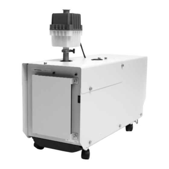
- Page 5 Agilent G3199 Series Quiet Cover Service Manual Introduction Parts Identification 6 Safety Information 9 This manual provides information for Agilent service representatives to support the Agilent G3199A Quiet Cover and G3199B Quiet Cover II. The G3199A is compatible with the BOC Edwards E1M18 pump used with the Agilent 1100/1200 LC/MS Series instruments.
-
Page 6: Parts Identification
Introduction Parts Identification Figures 1-4 point out the main components of the internal Quiet Cover. G1099-60564 Alarm 5188-1177 Fan cable Fan connector Thermostat 5188-1176 (G3199A)* (included in wiring Power connector harness) Wiring harness 5188-1163 Figure 1 Quiet Cover (internal view of rear panel). * Thermostat part number for G3199B is 5188-6570. - Page 7 Introduction On/off switch 5188-1178 Power (green) LED 5188-1180 Ferrite (part of wiring harness 5188-1163) Temperature alarm (red) LED 5188-1179 Figure 2 Quiet Cover (internal view of front panel). Wiring harness 5188-1163 Figure 3 Internal view showing rear part of wiring harness. Service Manual...
- Page 8 Introduction Wiring harness Wiring harness Figure 4 Internal view showing front part of wiring harness. Service Manual...
-
Page 9: Safety Information
The Quiet Cover is designed and manufactured under a quality system registered to ISO 9001. Information The Agilent Technologies Quiet Cover meets the following IEC classifications: Category II, Pollution Degree 2, Class III. Quiet Cover has been designed and tested in accordance with recognized safety standards and is designed for use indoors. - Page 10 Failure to comply with these precautions violates safety standards of design and the intended use of the instrument. Agilent Technologies assumes no liability for the customer’s failure to comply with these requirements. Table 1 lists the safety symbols that may appear on Quiet Cover.
- Page 11 Introduction While running Quiet Cover: CAU TI O N • Do not block air flow to the fans. • Do not set items on top of Quiet Cover. • It is important that the Quiet Cover not recirculate hot air. Always position the front end of the Quiet Cover where it can draw cool air.
- Page 12 Introduction • Consult your equipment dealer, Agilent Technologies, or an experienced technician for assistance. • Changes or modifications not expressly approved by Agilent Technologies could void the user’s authority to operate the equipment. Sound emission declaration • Sound pressure – Lp < 70 dB am according to EN 27779:1991.
-
Page 13: Replacement Procedures
Agilent G3199 Series Quiet Cover Service Manual Replacement Procedures Preparing Quiet Cover for Repair 14 Replacing a Fan 16 Replacing the Alarm 19 Replacing the Thermostat 20 Replacing the On/Off Switch 21 Replacing an LED 22 Replacing the Wiring Harness 23... -
Page 14: Preparing Quiet Cover For Repair
Replacement Procedures Preparing Quiet Cover for Repair Before performing any replacement procedures on the Quiet Cover, prepare it for service as described below. Required tools • 5/16-inch open-end wrench Procedure 1 Turn off and unplug Quiet Cover. 2 Remove the two pump access panels by loosening the thumbscrews on the top and sides. - Page 15 Replacement Procedures c Remove the grommet from around the cord and slide the grommet back into the groove in the frame for safekeeping. d Pick up the pump and remove it from Quiet Cover. Use two people to lift the pump. e Loosely thread the nuts back onto the vibration mounts for safekeeping.
-
Page 16: Replacing A Fan
Replacement Procedures Replacing a Fan Required tools • Phillips screwdriver • A wrench for #8–32 nut Procedure To remove the old fan 1 Perform the steps under “Preparing Quiet Cover for Repair” on page 14. 2 Disconnect the fan cable at the fan connector of the wiring harness. (See Figure 6.) Disconnect here Fan connector... - Page 17 Replacement Procedures 3 Remove the baffle (metal plate covering the fans on the outside of the Quiet Cover). There are six screws that hold it in place. (See Figure 7.) Hold the standoffs behind the baffle to prevent them from turning. Figure 7 Rear baffle, showing its six screws.
- Page 18 Replacement Procedures 2 Place the outside finger guard (with the countersunk screw holes facing out) on the outside of the Quiet Cover. 3 Feed one screw, with the white insert facing out, through the outer finger guard and the Quiet Cover wall. 4 Install a fan spacer into the fan, and slide the screw all the way in.
-
Page 19: Replacing The Alarm
Replacement Procedures Replacing the Alarm Required tools None Procedure 1 Perform the steps under “Preparing Quiet Cover for Repair” on page 14. 2 Remove the wires (marked ALRM + and ALRM –) from the alarm. (See Figure 10.) Connectors Figure 10 Inside view of the back of alarm. -
Page 20: Replacing The Thermostat
Replacement Procedures Replacing the Thermostat Required tools • Phillips screwdriver Procedure 1 Perform the steps under “Preparing Quiet Cover for Repair” on page 14. 2 Remove the two wires THERM-1 and THERM-2 from the thermostat. G3199A part number 5188-1176 G3199B part number 5188-6570 Figure 12 Thermostat. -
Page 21: Replacing The On/Off Switch
Replacement Procedures Replacing the On/Off Switch Required tools None Procedure 1 Perform the steps under “Preparing Quiet Cover for Repair” on page 14. 2 Inside the cabinet remove the two wires SW-1 and SW-2 from the on/off switch. (See Figure 13.) Remove wires Figure 13 Wires to remove from the on/off switch. -
Page 22: Replacing An Led
Replacement Procedures Replacing an LED Required tools • A wrench for #6–32 nut Procedure 1 Perform the steps under “Preparing Quiet Cover for Repair” on page 14. 2 Remove the + and – wires (marked GLED+/– or RLED+/–) from the faulty LED. -
Page 23: Replacing The Wiring Harness
Replacement Procedures Replacing the Wiring Harness Required tools • Pliers with wire cutter • Phillips screwdriver Procedure To remove the old wiring harness 1 Perform the steps under “Preparing Quiet Cover for Repair” on page 14. 2 Disconnect the wiring harness connections for the alarm, fans, thermostat, on/off switch, and LEDs. - Page 24 Replacement Procedures To connect the new wiring harness 1 Install the new power connector into the back of the Quiet Cover using the same screws as before. Pinhole 1 should be on the top inside and pinhole 4 should be on the bottom. (Pinholes 2 and 3 are horizontal from each other and used for the electrical connection in step 4.) 2 Place the new wiring harness along the side rail of the Quiet Cover, with the ferrite end at the front of the box.
- Page 25 Replacement Procedures 5 Verify that the oil tray does not pinch any of the wires when sliding the oil tray in and out of the Quiet Cover. Service Manual...
- Page 26 Replacement Procedures Service Manual...
-
Page 27: Replaceable Parts
Agilent G3199 Series Quiet Cover Service Manual Replaceable Parts Table 2 lists the G3199 Series Quiet Cover’s replaceable parts. Table 2 Replaceable parts Part Part number Locking front caster (G3199A) 5188-1173 Non-locking back caster (G3199A) 5188-1174 Caster (G3199B) 5188-6571 On/off switch... - Page 28 Replaceable Parts Table 2 Replaceable parts (continued) Part Part number Pin extraction tool (for power connector) 8710-0614 Service Manual...