Tadiran Telecom Emerald ICE Installation & Maintenance Manual
Digital key telephone system
Hide thumbs
Also See for Emerald ICE:
- Installation manual (169 pages) ,
- Quick installation manual (138 pages) ,
- User manual (122 pages)
Table of Contents
Advertisement
Quick Links
Advertisement
Table of Contents

Related Manuals for Tadiran Telecom Emerald ICE


Summary of Contents for Tadiran Telecom Emerald ICE
-
Page 1: Telephone System
Emerald ICE Digital Key Telephone System Installation & Maintenance Manual... - Page 2 Record of Revisions Revision Date of Issue Supercedes Major Changes - Brief Description Revision A February 6, 2004 Initial Release Changed Automated Attendant procedures. Miscellaneous other revisions. Revision B March 3, 2004 Revision A Revised System and Extension Speed Dial information.
- Page 4 FEDERAL COMMUNICATIONS COMMISSION RULES PART 68 COMPLIANCE STATEMENT This equipment complies with Part 68 of the FCC rules. On the left side of the interior card frame (Coral I‐S, Coral I, and Coral II systems); or inside the rear doors on the left side of the cabinet frame (Coral III cabinets) of this equipment is a label that contains, among other information, the FCC registration number and ringer equivalence number (REN) for this equipment. If requested, this information must be provided to the telephone company. The REN is used to determine the quantity of devices which may be connected to the telephone line. Excessive REN’s on the telephone line may result in the devices not ringing in response to an incoming call. In most, but not all areas, the sum of the REN’s should not exceed five (5.0). To be certain of the number of devices that may be connected to the line, as determined by the total REN’s contact the telephone company to determine the maximum REN for the calling area. An FCC compliant telephone cord and modular plug is provided with this equipment. This equipment is designed to be connected to the telephone network or premises wiring using a compatible modular jack which is Part 68 compliant. This equipment cannot be used on telephone company‐provided coin service. Connection to Party Line Service is subject to state tariffs. If this equipment causes harm to the telephone network, the telephone company will notify you in advance that temporary discontinuance of service may be required. If advance notice is not practical, the telephone company will notify the customer as soon as possible. Also, you will be advised of your right to file a complaint with the FCC if you believe it is necessary. The telephone company may make changes in its facilities, equipment, operations, or procedures that could affect the operation of the equipment. If this happens, the telephone company will provide advance notice in order for you to make the necessary modifications in order to maintain uninterrupted service. If trouble is experienced with this equipment, please Contact Tadiran Telecom at: (813) 523‐0000 for repair and/or warranty information. If the trouble is causing harm to the telephone network, the ...
- Page 5 FEDERAL COMMUNICATIONS COMMISSION RADIO FREQUENCY INTERFERENCE STATEMENT The Coral system generates, uses, and can radiate radio energy; and, if not installed in strict accordance with this installation manual, may cause harmful interference to radio communications. This equipment has been tested and found to comply with the limits for a Class A digital device, pursuant to Subpart J of Part 15 of FCC Rules, which are designed to provide reasonable protection against such interference when this equipment is operated in a commercial environment. Operation of this equipment in a residential area is likely to cause unacceptable interference to radio and TV reception, in which case the operator at his own expense will be required to take whatever measures may be necessary to correct the interference. To ensure continued compliance with specified radio energy emissions limits of FCC Rules, the following precautions must be observed while installing and operating the equipment: 1. Install the equipment in strict accordance with the manufacturer’s instructions. 2. Verify that the power supply and associated A.C. powered equipment are connected to a properly grounded electrical supply, and that power cords, if used, are unmodified. 3. Verify that the system grounding, including Master Ground, D.C. power system, and equipment cabinets, is in accordance with the manufacturer’s instructions and connected to an approved earth ground source. 4. Always replace the factory‐supplied cover or keep the cabinet doors closed when not servicing the equipment. 5. Make no modification to the equipment that would affect its compliance with the specified limits of FCC Rules. 6. Maintain the equipment in a satisfactory state of repair. 7. Verify that emissions limiting devices, such as ferrite blocks and radio frequency interference modules, are properly installed and functional. If necessary the operator should consult their Supplier, Tadiran Telecom,Inc. or an experienced radio/television engineer for additional suggestions. The following booklet prepared by the Federal Communications Commission may be of assistance: “How to Identify and Resolve ...
- Page 6 7-15 Automated Attendant Automatic CO Line Ringing Modes 12-5 Automatic Selection (CO/Intercom) 13-8 Auto-Record Auxiliary Lamp / LED Status Bar 13-9 Background Music (BGM) 13-11 Battery Back-Up (Memory) 13-12 Battery Back-Up (System) 13-13 Emerald ICE Installation, Programming & Maintenance Manual...
- Page 7 Camp On (Extension) 13-27 Class of Service – Extension CO Line Alternate Route 11-1 CO Line Assignment CO Line Calling & I-Use Indication 13-28 CO Line Group CO Line Group Directory Number Swapping 11-10 Emerald ICE Installation, Programming & Maintenance Manual...
- Page 8 Direct Station Selection Console (DSS) 8-13 Directory/Feature/Suffix Code Lookup 13-42 Distinctive Ringing – CO Line 6-24 Distinctive Ringing – Extension 13-33 Do Not Disturb 13-34 Do Not Disturb (One Time) 13-36 Do Not Disturb (Override) 13-37 Emerald ICE Installation, Programming & Maintenance Manual...
- Page 9 13-44 Feature/DSS Button Reset 13-41 Flash – Analog Port (SLT) Flash Recognition 7-47 Flash – CO Line 7-50 Flash – PBX Line 7-52 Forced Intercom (Call Forward) 13-46 Forced Intercom Tone Ring 13-47 Emerald ICE Installation, Programming & Maintenance Manual...
- Page 10 Meet Me Conference 7-33 Meet Me Page 13-62 Messaging – Call Me, Text or Voice 8-23 Messaging – Status Text 8-25 Modem 8-27 Monitor-Extension-CO Line 5-23 Music On Hold (Two Source) 6-26 Mute 13-64 Emerald ICE Installation, Programming & Maintenance Manual...
- Page 11 Reminder Tones 13-77 Remote RMP Programming Setup Parameters 8-29 Ring Scheme 12-15 Ringing Level / Muted Ringing 13-78 Ringing Line Priority 13-79 Saved Number Redial 13-80 Single Line Telephone – CO Line Flash 13-81 Emerald ICE Installation, Programming & Maintenance Manual...
- Page 12 5-41 Voice Announce 13-58 Voice Call Recorder (via voicemail System) 5-45 Voice Page (Allow/Deny) 13-69 Voicemail – Analog Integration 5-47 Voicemail – Digital Integration 10-19 Warning Tone / CO Line Call Limiter 5-57 Emerald ICE Installation, Programming & Maintenance Manual...
-
Page 13: Table Of Contents
3 Installation........................3‐1 3.1 Installation Outline . . . . . . . . . . . . . . . . . . . . . . . . . . . . . . . . . . . . . . . . . . . . . . . . . . . . . . . . . 3‐1 3.2 Site Planning . . . . . . . . . . . . . . . . . . . . . . . . . . . . . . . . . . . . . . . . . . . . . . . . . . . . . . . . . . . . . . 3‐3 3.3 RMP Installation . . . . . . . . . . . . . . . . . . . . . . . . . . . . . . . . . . . . . . . . . . . . . . . . . . . . . . . . . . 3‐15 3.4 KSU Initialization Procedure . . . . . . . . . . . . . . . . . . . . . . . . . . . . . . . . . . . . . . . . . . . . . . . 3‐17 4 Basic Programming...................... 4‐1 4.1 General . . . . . . . . . . . . . . . . . . . . . . . . . . . . . . . . . . . . . . . . . . . . . . . . . . . . . . . . . . . . . . . . . . . 4‐1 4.2 Deluxe Telephone Programming Access. . . . . . . . . . . . . . . . . . . . . . . . . . . . . . . . . . . . . . . 4‐2 4.3 Accessing and Sending Modifications to the RMP . . . . . . . . . . . . . . . . . . . . . . . . . . . . . . 4‐9 viii Emerald ICE Installation, Programming & Maintenance Manual... - Page 14 6.5 CO Line Ring Assignment (Answer Position) . . . . . . . . . . . . . . . . . . . . . . . . . . . . . . . . . . 6‐13 6.6 CO Line Ring Type Assignment . . . . . . . . . . . . . . . . . . . . . . . . . . . . . . . . . . . . . . . . . . . . . 6‐15 6.7 CO Line Ringing Modes . . . . . . . . . . . . . . . . . . . . . . . . . . . . . . . . . . . . . . . . . . . . . . . . . . . . 6‐17 6.8 CO Line Signaling / Dialing Type (Tone/Pulse) . . . . . . . . . . . . . . . . . . . . . . . . . . . . . . . . . 6‐20 6.9 CO Line Type Assignment (Trunk Type) . . . . . . . . . . . . . . . . . . . . . . . . . . . . . . . . . . . . . . 6‐22 6.10 Distinctive Ringing – CO Line . . . . . . . . . . . . . . . . . . . . . . . . . . . . . . . . . . . . . . . . . . . . . . 6‐24 6.11 Music On Hold (Two Source) . . . . . . . . . . . . . . . . . . . . . . . . . . . . . . . . . . . . . . . . . . . . . . . 6‐26 6.12 Privacy Release . . . . . . . . . . . . . . . . . . . . . . . . . . . . . . . . . . . . . . . . . . . . . . . . . . . . . . . . . . . 6‐28 6.13 Private Line . . . . . . . . . . . . . . . . . . . . . . . . . . . . . . . . . . . . . . . . . . . . . . . . . . . . . . . . . . . . . . 6‐30 Emerald ICE Installation, Programming & Maintenance Manual...
- Page 15 8.5 CO Line Name / Label Programming . . . . . . . . . . . . . . . . . . . . . . . . . . . . . . . . . . . . . . . . 8‐11 8.6 Direct Station Selection Console (DSS) . . . . . . . . . . . . . . . . . . . . . . . . . . . . . . . . . . . . . . . 8‐13 8.7 Extension Password . . . . . . . . . . . . . . . . . . . . . . . . . . . . . . . . . . . . . . . . . . . . . . . . . . . . . . . 8‐16 8.8 Extension User Name. . . . . . . . . . . . . . . . . . . . . . . . . . . . . . . . . . . . . . . . . . . . . . . . . . . . . . 8‐18 8.9 Loud Bell / External Page / Music Source – Control . . . . . . . . . . . . . . . . . . . . . . . . . . . . 8‐20 8.10 Messaging – Call Me, Text or Voice . . . . . . . . . . . . . . . . . . . . . . . . . . . . . . . . . . . . . . . . . 8‐23 8.11 Messaging – Status Text . . . . . . . . . . . . . . . . . . . . . . . . . . . . . . . . . . . . . . . . . . . . . . . . . . . 8‐25 8.12 Modem . . . . . . . . . . . . . . . . . . . . . . . . . . . . . . . . . . . . . . . . . . . . . . . . . . . . . . . . . . . . . . . . . 8‐27 8.13 Remote RMP Programming Setup Parameters . . . . . . . . . . . . . . . . . . . . . . . . . . . . . . . 8‐29 8.14 Speed Dialing – Extension/System . . . . . . . . . . . . . . . . . . . . . . . . . . . . . . . . . . . . . . . . . . 8‐33 Emerald ICE Installation, Programming & Maintenance Manual...
- Page 16 12.1 12/24‐Hour Mode Selection . . . . . . . . . . . . . . . . . . . . . . . . . . . . . . . . . . . . . . . . . . . . . . . . 12‐1 12.2 System Time and Date. . . . . . . . . . . . . . . . . . . . . . . . . . . . . . . . . . . . . . . . . . . . . . . . . . . . . 12‐3 12.3 Automatic CO Line Ringing Modes . . . . . . . . . . . . . . . . . . . . . . . . . . . . . . . . . . . . . . . . . 12‐5 12.4 Call Pickup‐Group . . . . . . . . . . . . . . . . . . . . . . . . . . . . . . . . . . . . . . . . . . . . . . . . . . . . . . . . 12‐8 12.5 CO Line Programming Copy . . . . . . . . . . . . . . . . . . . . . . . . . . . . . . . . . . . . . . . . . . . . . . . 12‐9 12.6 Extension Programming Copy. . . . . . . . . . . . . . . . . . . . . . . . . . . . . . . . . . . . . . . . . . . . . 12‐12 12.7 Ring Scheme . . . . . . . . . . . . . . . . . . . . . . . . . . . . . . . . . . . . . . . . . . . . . . . . . . . . . . . . . . . . 12‐15 12.8 External Music Source (Two Standard). . . . . . . . . . . . . . . . . . . . . . . . . . . . . . . . . . . . . . 12‐17 12.9 External Paging. . . . . . . . . . . . . . . . . . . . . . . . . . . . . . . . . . . . . . . . . . . . . . . . . . . . . . . . . . 12‐19 12.10 Numbering Plan . . . . . . . . . . . . . . . . . . . . . . . . . . . . . . . . . . . . . . . . . . . . . . . . . . . . . . . . 12‐21 Emerald ICE Installation, Programming & Maintenance Manual...
- Page 17 13.39 Hot Key Enable/Disable . . . . . . . . . . . . . . . . . . . . . . . . . . . . . . . . . . . . . . . . . . . . . . . . . 13‐54 13.40 Hot Line . . . . . . . . . . . . . . . . . . . . . . . . . . . . . . . . . . . . . . . . . . . . . . . . . . . . . . . . . . . . . . 13‐55 13.41 Making an Intercom Call . . . . . . . . . . . . . . . . . . . . . . . . . . . . . . . . . . . . . . . . . . . . . . . . 13‐57 13.42 Voice Announce . . . . . . . . . . . . . . . . . . . . . . . . . . . . . . . . . . . . . . . . . . . . . . . . . . . . . . . 13‐58 13.43 Last Number Redial . . . . . . . . . . . . . . . . . . . . . . . . . . . . . . . . . . . . . . . . . . . . . . . . . . . . 13‐60 13.44 Meet Me Page . . . . . . . . . . . . . . . . . . . . . . . . . . . . . . . . . . . . . . . . . . . . . . . . . . . . . . . . . 13‐62 13.45 Note Pad . . . . . . . . . . . . . . . . . . . . . . . . . . . . . . . . . . . . . . . . . . . . . . . . . . . . . . . . . . . . . . 13‐63 13.46 Mute . . . . . . . . . . . . . . . . . . . . . . . . . . . . . . . . . . . . . . . . . . . . . . . . . . . . . . . . . . . . . . . . . 13‐64 13.47 Night Mode/Activate . . . . . . . . . . . . . . . . . . . . . . . . . . . . . . . . . . . . . . . . . . . . . . . . . . . 13‐65 13.48 Making Off‐Hook Voice Announcements. . . . . . . . . . . . . . . . . . . . . . . . . . . . . . . . . . 13‐66 Emerald ICE Installation, Programming & Maintenance Manual...
- Page 18 13.62 Speakerphone . . . . . . . . . . . . . . . . . . . . . . . . . . . . . . . . . . . . . . . . . . . . . . . . . . . . . . . . . . 13‐84 13.63 Transfer and Answer Call . . . . . . . . . . . . . . . . . . . . . . . . . . . . . . . . . . . . . . . . . . . . . . . . 13‐85 13.64 UCD Agent Log Off/Log On . . . . . . . . . . . . . . . . . . . . . . . . . . . . . . . . . . . . . . . . . . . . . 13‐86 13.65 UCD Overflow and Reroute. . . . . . . . . . . . . . . . . . . . . . . . . . . . . . . . . . . . . . . . . . . . . . 13‐87 Appendix A Door Phone Installation ................A‐1 A.1 General . . . . . . . . . . . . . . . . . . . . . . . . . . . . . . . . . . . . . . . . . . . . . . . . . . . . . . . . . . . . . . . . . . A‐1 A.2 Hardware Installation . . . . . . . . . . . . . . . . . . . . . . . . . . . . . . . . . . . . . . . . . . . . . . . . . . . . . A‐3 A.3 Programming. . . . . . . . . . . . . . . . . . . . . . . . . . . . . . . . . . . . . . . . . . . . . . . . . . . . . . . . . . . . . A‐6 Appendix B Feature Codes ..................... B‐1 Appendix C Programming Quick Reference Charts........... C‐1 xiii Emerald ICE Installation, Programming & Maintenance Manual...
- Page 19 Emerald ICE Installation, Programming & Maintenance Manual...
-
Page 20: Introduction
Introduction The Tadiran Emerald Integrated Communication Exchange, (ICE) is a versatile, Digital Hybrid Key Telephone System that includes many advanced features. It is designed to meet the telecommunications needs of small to medium business offices. The Emerald ICE is a fully digital hybrid key telephone system. Utilizing “Loop Start” central office (Telephone Company) line interfaces in conjunction with analog and digital extension ports, it provides office communications and connectivity to the Public Switched Telephone Network (PSTN). The Emerald ICE offers a plethora of office productivity features and telephone enhancing features that include Caller Identification (required Telephone Company subscription) in the standard package. Unlike most systems that support Caller ID, the Emerald ICE supports Caller ID to Emerald ICE proprietary digital extensions and to third‐party, Caller ID capable analog devices (cordless telephones, etc.) In addition to many standard features, several optional features are offered to further enhance office communications. These built‐in voice processing integration packages are: • Automated Attendant • Both Flash and Hard Drive Based Voicemail/Auto Attendant The Emerald ICE platform allows the application of these voice processing platforms without loss of valuable system port resources. The Emerald ICE is comprised of an application‐configured, expandable Key Service Unit or KSU platform. When used with the full‐featured Deluxe Telephone and its display, it provides access to all system functions. The Emerald ICE system architecture provides an expandable interface for digital port growth and analog port growth. The basic configuration supports both device types. (Analog ports might be used for plain old telephones, fax machines, modems, etc.) Emerald ICE Installation, Programming & Maintenance Manual... - Page 21 An illustration of the ICE cabinet and 2 Key Telephone Sets are shown below in Figure 1. Figure 1-1 ICE Digital Hybrid Key Telephone System Emerald ICE KSU Emerald ICE Deluxe Model Telephone Emerald ICE Standard Model Telephone The Emerald ICE incorporates state‐of‐the‐art digital technology for voice switching and call processing utilizing Pulse Code Modulation and Time Division Multiplexing (PCM/TDM). The Emerald ICE is a non‐blocking switch featuring no degradation of voice signals. The system utilizes a 16‐bit, 20 MHz main microprocessor and peripheral device (extensions and CO lines) processors in a distributed processing configuration. Memory consists of 640K bytes of ROM and 384K bytes of RAM. Emerald ICE Installation, Programming & Maintenance Manual...
- Page 22 The Emerald ICE is shipped as follows: • 1‐KSU with the following: ‐Ten (10) digital extension ports. ‐Two (2) analog device ports. ‐Six (6) CID‐ready CO Line ports. ‐Two music source enters (can be assigned as desired to CO lines for hold music/messages. ‐One power failure port (CO Line 1). ‐One control contact (LBC, Gate, External Page Control). ‐One external paging equipment interface. ‐Two serial ports. ‐PC‐RMP Programming Interface. ‐SMDR (Station Message Detailed Recording). Emerald ICE Installation, Programming & Maintenance Manual...
- Page 23 • Section 6 ‐ Phone Trunk Programming (02) ‐ This section provides Deluxe and RMP programming instructions for the Emerald ICE features such as Call Forwarding with Predefined CO Lines, CO Line Group Programming, CO Line Ring Assignments and others. • Section 7 ‐ Phone Call Handling Programming (03) ‐ This section provides Deluxe and RMP programming instructions for the Emerald ICE features such as Alarm Clock‐Extension, Alarm Clock‐System, Answering Machine Emula‐ tion, Auto Attendant and others. • Section 8 ‐ Phone System Resource Handling (04) ‐ This section provides Deluxe and RMP programming instructions for the Emerald ICE features such as Attendant Programming, DSS Console Programming, Call Opera‐ tor‐Attendant, Extension Passwords and others. • Section 9 ‐ Phone Restriction Programming (05) ‐ This section provides Deluxe and RMP programming instructions for the Emerald ICE features such as Account Code ‐ Voluntary/Forced/Verified, Toll Restriction‐COS and oth‐ ers. • Section 10 ‐ Phone Trunk Application Programming (06) ‐ This section pro‐ vides Deluxe and RMP programming instructions for the Emerald ICE fea‐ tures such as Voice Mail‐Digital Integration and others. • Section 11 ‐ Phone Extension Application Programming (07) ‐This section provides Deluxe and RMP programming instructions for the Emerald ICE features such as CO Line Alternate Route, Fax Tone Detection and others. • Section 12 ‐ Phone System Application Programming (08) ‐ This section pro‐ vides Deluxe and RMP programming instructions for the Emerald ICE fea‐ tures such as 12/24‐Hour Mode Selection, Automatic CO Line Ringing Modes, Call Pickup‐Group and others. Emerald ICE Installation, Programming & Maintenance Manual...
- Page 24 Document Conventions The following conventions are used throughout this manual. Table 1-1 Conventions Convention Description Normal Used in body text throughout this manual. Normal, Italic Used in referencing sections, telephone features and voice recordings or prompts. Bold, Italic Used in describing the fields in RMP screens and other form names or items. Normal, Bold Used to describe filenames, device names and specific areas of RMP menus. Press Means to press a specific key. (e.g. press ESC means to press and release the Escape key.) Enter Means to type or push a button on the telephone keypad. Indicates the keystrokes that are required to be (Telephone Keys) entered on a telephone. DISPLAY FONT Indicates a display on a Deluxe Model Telephone. Emerald ICE Installation, Programming & Maintenance Manual...
- Page 25 Related Documents The following documents should be used in conjunction with this manual: • Emerald ICE Deluxe Model Telephone User Guide • Emerald ICE Standard Model Telephone User Guide • Emerald ICE Flash Voicemail Installation & Maintenance Manual • Emerald ICE HD Voicemail Installation & Maintenance Manual Emerald ICE Installation, Programming & Maintenance Manual...
-
Page 26: System Design
System Design Key Service Unit (KSU) The Emerald ICE Key Service Unit (KSU) is designed as a modularized, flat‐pack. Two KSU’s (KSU1 and KSU2) may be equipped to attain the total system capacity of 24 CO lines, 58 Extensions (46 digital and 18 analog) and 8 Voice Processing Channels. Each KSU is designed to be mounted on the wall and is shipped with a wall mounting template. The compact KSU weighs less than 20 pounds and is UL Listed. If using 2 KSU’s, the first KSU, or KSU1 is factory equipped with one 610+2 Board, one CCB (Common Control Board). The second KSU or KSU2 is factory equipped with one Base Board module. Each KSU is a self‐contained cabinet containing an internal power supply for either 117vac or 230vac operation. At the time of shipping it is set for 117vac operation. From the exterior, with covers in place, KSU1 and KSU2 look identical, however, KSU1 contains the Common Control Board(CCB). Figure 2-1 Emerald ICE Emerald ICE Installation & Hardware Reference Manual... -
Page 27: Power Supply
Power Supply The power supply circuitry of the Emerald ICE incorporates a linear design AC transformer with a choice of enter voltage taps. The transformer primary windings are shipped wired for 117vac applications. A factory provided switch alternates between 230vac and 117vac applications. The output voltage is delivered to the 610+2 Board(in KSU1, Base Board in KSU2) for voltage regulation. All system operation and logic voltages are produced at these boards. Two fuses are provided on the power supply board; one for ac enter over‐voltage protection and one for DC output over‐current protection. A main power switch is accessible on the side of each KSU. In the event battery backup operation is desired the KSU power cord can be connected with an external (ancillary) UPS (Uninterruptible Power Supply). It is the responsibility of the installer to match the battery requirements/UPS requirement to the specific needs of the equipment owner. Figure 2-2 Power Supply 115V/230V Switch Main Power Switch (Side of Cabinet) 2 Fuses Emerald ICE Installation & Hardware Reference Manual... -
Page 28: Battery Charger Board (Optional)
Battery Charger Board (Optional) An optional battery charger card is available for connection with the power supply. This card is mounted on the power supply voltage regulator using 3 supplied standoffs. It provides a third‐party 24 volt, lead‐acid battery with .4 amps of constant current. Relays on the battery charger card detect voltages over 24 volts to deactivate charging, while activating charging for voltages less than 24 volts. Figure 2-3 Battery Charger To Battery To Power Supply Manual Shutoff Emerald ICE Installation & Hardware Reference Manual... -
Page 29: Ccb (Common Control Board)
CCB (Common Control Board) The CCB module is equipped standard in KSU1. This board contains all circuitry required to control the fully equipped Emerald ICE. All digital voice switching and call processing data switching is accomplished via the CCB. The CCB has one ribbon cable connector for connection to the KSU1 610+2 board and five (5) connector sockets for connection of the system built‐in modem, voice processor and 2nd Cabinet (KSU2). Since the CCB comes installed inside of KSU1 the CCB ribbon cable is already in place and connected to the KSU1‐610+2. Assuming the orientation of the KSU1 cabinet is installed on the wall; the two horizontal connector sockets in the lower left corner of the CCB are for the Modem Module. The connector socket labeled “2nd Cabinet” is for connection to the KSU2‐Base Board if that expansion is required. The remaining two connector sockets on the CCB, one at the left side, the other at the right side are for the voice processor solution. (The voice processor solution can be any of three possible choices; 4VAA, Flash Voicemail or HD Voicemail.) Figure 2-4 CCB Board Emerald ICE Installation & Hardware Reference Manual... - Page 30 The CCB also provides the following standard connectors: • Music Channel 1 ‐ On Hold/Background Music Interface • Music Channel 2 ‐ On Hold/Background Music Interface • Control Contact (Loud Bell or External Page Relay) • External Paging Equipment Interface • RMP Serial Port ‐ for on‐site database programming • SMDR Serial Port ‐ for connection to ancillary SMDR/Call Accounting equip‐ ment The CCB has two Option Strap jumpers one for database start‐up (J7) and one for Music Channel One source (internal/external) selection (JP81). • JP7 Cold Start/Normal : JP7 is used to force load database default factory settings. This jumper will normally never require operation after the initial power up sequence is completed. However should the need arise to return the site database to the factory settings this jumper is used to accomplish the task. • JP81 Internal/External: J81 is used to select the Music Channel 1 source. The Emerald ICE provides a synthesized music source for music on hold in appli‐ cations where no music source is available. The synthesized tune is repeated. JP81 is in the “External” position when it ships from the factory. The CCB is equipped with a Heart‐beat LED that indicates processing activity on the PCB. (The 610+2 peripheral processor is operating when the Heartbeat LED is flashing.) The KSU1 operation LED (located next to the power switch) is tied to the CCB Heartbeat LED. Therefore, when the LED next to the power switch is flashing, the CCB is active.. Emerald ICE Installation & Hardware Reference Manual...
-
Page 31: 610+2 (Ksu1 Component)
610+2 (KSU1 Component) The 610+2 is the large circuit board that is packaged inside of KSU1. It 610+2 provides interface for up to 6 loop‐start CO Lines, 10 Digital Extension Ports and 2 analog ports. Additionally the 610+2 regulates the 24 volt DC power from the source to produce all required logic voltages and operations voltages. There is also a Power Failure Port located on the 610+2 that is connected to the first CO Line circuit. Whenever power fails this port becomes active with dial tone from the CO line connected to the first CO line port. Figure 2-5 610+2 Board Each CO line circuit on the 610+2 board incorporates over‐voltage protection, ring detector, loop detector, loop/pulse‐dial relay, current sink circuit, coupling/isolation transformer (impedance 600:600), hybrid circuit, CODEC & filter, polarity guard circuit and Radio Frequency noise filter. The sixth CO Line port is equipped with CNG Fax Tone Detection circuitry. If FAX tone is detected, the call is routed to the analog port designated as the destination for fax calls. Each digital port (connects to Deluxe & Standard Telephones and DSS Consoles) is comprised of a proprietary octal ASIC (Application Specific Integrated Circuit) transceiver. There are three data channels in operation at each digital port via the octal transceiver. One channel is used for call processing control of digital terminal Emerald ICE Installation & Hardware Reference Manual... - Page 32 Each digital station interface is protected against circuit wiring shorts by an over‐current protection Polyswitch. The digital station circuit requires only one cable pair to operate and is not polarity sensitive. Physical connection of digital extensions, power failure telephones and CO lines to the 610+2 board is made through a 25 pair amphenol connector to be terminated on the MDF. (Main Distribution Frame) Emerald ICE Installation & Hardware Reference Manual...
-
Page 33: Base Board
Base Board The Base Board is unique to KSU2. It provides connecitivity with peripheral boards. Additionally the Base Board regulates the 24 volt DC power from the source to produce all required logic voltages and operations voltages. The KSU2 operation LED (located next to the power switch) is tied to the CCB (KSU1) LED. Therefore, when the LED next to the power switch is flashing, the CCB (KSU1) is active. A long shielded cable is used to connect KSU2 to the CCCB inside of KSU1. Each digital station interface is protected against circuit wiring shorts by an over‐current protection Polyswitch. The digital station circuit requires only one cable pair to operate and is not polarity sensitive. Figure 2-6 Base Board Emerald ICE Installation & Hardware Reference Manual... -
Page 34: 4Slt Board (Analog Port Module-4 Circuits)
4SLT Board (Analog Port Module-4 Circuits) The 4SLT Board provides four separate analog device ports. This allows the Emerald ICE to support auxiliary office equipment found on the business premises such as fax machines, PC/Mac modems and analog telephones (single line telephones). The 4SLT Board generates ‐30VDC and 20‐25Hz, 50V square wave ringing for operation. The 4SLT Board is equipped with a Heartbeat LED that indicates processing activity on the PCB. (The 4SLT Board peripheral processor is operating when the Heartbeat LED is flashing.) The 4SLT Board provides DTMF receivers for each analog port. Ancillary analog devices connected to 4SLT analog ports must generate DTMF signaling. (Pulse dial (rotary‐dial) telephones/equipment are not supported.) All connections are via RJ‐11 connectors along the top edge of the module. Up to 2‐ 4SLT Boards may be installed on 610+2 Board and up to 2 in the Expansion Cabinet. Figure 2-7 4SLT Board Emerald ICE Installation & Hardware Reference Manual... -
Page 35: 12Ekt (Digital Port Module - 12 Circuits)
12EKT (Digital Port Module - 12 Circuits) The 12EKT module expands the Emerald ICE system capacity of digital ports Deluxe & Standard Telephones and DSS Consoles. Each digital port is comprised of a proprietary octal ASIC (Application Specific Integrated Circuit) transceiver. There are three data channels in operation at each digital port via the octal transceiver. One channel is used for call processing control of digital terminal functions/operations and two channels are used for the digital voice channel requirements. The 12EKT is controlled directly from the 610+2 Board/Base Board. Each digital station interface is protected against circuit wiring shorts by an over‐current protection Polyswitch. The digital station circuit requires only one cable pair to operate and is not polarity sensitive. Physical connection of digital port terminals (Deluxe & Standard Telephone and DSS) to the 12EKT module is made through a 25‐pair amphenol connector along the top edge of the module. 1 Additional 12EKT module can be added to KSU1 and 2 in KSU2. Figure 2-8 12EKT Card 2-10 Emerald ICE Installation & Hardware Reference Manual... -
Page 36: 6Co Board (Central Office Module - 6 Circuits)
6CO Board (Central Office Module - 6 Circuits) The 6CO Board is installed in the dedicated position of the 610+2 Board/Base Board. The 6CO interfaces 6 loopstart CO (Central Office [Telephone Company]) lines. One 6CO Board is installed in KSU1. An additional 6CO Board can be added for a total of 12 loopstart CO lines. Two 6CO Boards may be installed in KSU2. Therefore, the Emerald ICE system CO line capacity may be expanded to interface 24 total loopstart CO lines. The 6CO module is shipped with four (4) mounting stand‐offs used to install the board into the KSU1 or KSU2. Each CO line circuit incorporates over‐voltage protection, ring detector, loop detector, loop/pulse‐dial relay, current sink circuit, coupling/isolation transformer (impedance 600:600), hybrid circuit, CODEC & filter, polarity guard circuit and Radio Frequency noise filter. The sixth CO Line port is equipped with CNG Fax Tone Detection circuitry. When programmed as a “FAX” line, this circuit will automatically engage the FAX Tone detector. If FAX tone is detected, the call is routed to the analog port designated as the destination for fax calls. Figure 2-9 6CO Board 2-11 Emerald ICE Installation & Hardware Reference Manual... -
Page 37: Modem Module
Modem Module 2.10 The Modem Module is a self‐contained integrated modem unit that is installed at J5 and J6 in the lower left corner of the CCB. The integrated Modem Module allows the servicing Telephone Company to access the telephone system programming and remote maintenance utilities from an off‐site location (password verification required). When installed, the servicing technician uses the RMP and a modem (in the PC) to place a call to the site where the Emerald ICE is installed. If one of the voice processing systems are installed, routing to the modem extension is automated. Otherwise the person who answered this data call must transfer the call to Extension 400 (Default). Once the modems have established the data connection, RMP may be used to perform all servicing operations. Figure 2-10 Modem Module The only configurable parameter in the Modem Module is the Baud Rate. Baud rate can be configured to 1200 or 2400 by using the RMP or the Deluxe Telephone set. 2-12 Emerald ICE Installation & Hardware Reference Manual... -
Page 38: Caller Id Module
If a Caller ID card is NOT installed on any 6CO board, the caller ID information will only be displayed if received on the first 6 CO lines contained on the 610+2 board. Figure 2-11 Caller ID Card 2-13 Emerald ICE Installation & Hardware Reference Manual... -
Page 39: 4Vaa Board (4-Port Voice Automated Attendant)
4VAA Board (4-Port Voice Automated Attendant) 2.12 The optionally available Automated Attendant Module is a self contained integrated module that adds automatic answering of selected CO lines and a single‐level menu for greeting callers and routing them to Emerald ICE system destinations. The 4VAA is a low cost voice processing system that can handle all call traffic or act as a backup to the primary answering system attendant. It should be used as an alternative to the HD Voicemail or Flash Voicemail systems. The 4VAA is installed at J3 and J4 of the CCB. The 4VAA provides 10 greetings for the various modes of system/action operation. They are: Day Greeting, Alt Greeting, Night Greeting, Waiting Message, Invalid Message, Busy Message, No Answer Message, Goodbye Message, Inquiry Message and Temporary Message. Figure 2-12 4VAA Board 2-14 Emerald ICE Installation & Hardware Reference Manual... -
Page 40: Battery Charger
Battery Charger 2.13 The Battery Charger is an optional board in the Emerald ICE system. It is connected to the AC Power Supply Board via a 3‐pin connector and mounted on the Power Supply Board with 3 standoffs. The Battery Charger can charge a 24v Lead‐Acid battery with .4 amp constant current and 26.4v nominal voltage. If the battery voltage is over 24 volts, a relay will activate turning the system off. If the battery voltage is under 24 volts the same relay turns the system on. The battery is a third‐party item that can be purchased separately. Figure 2-13 Battery Charger Module 2-15 Emerald ICE Installation & Hardware Reference Manual... -
Page 41: Deluxe Model Telephone
This feature requires a subscription from the servicing telephone company. The display provides a visual reference to call progress and call duration, as well as time and date information. The display also enables the user to send and receive visual advisory and callback messages. Users may select from six “canned” messages (i.e., “IN A MEETING,” “OUT OF OFFICE”), or they may create a custom message. Calls from other Emerald ICE telephone users to an extension with a message active will receive the visual advisory message on their LCD display. Each Deluxe Telephone has twenty‐eight (28) Programmable Feature Buttons to aid the user by providing direct access to system features and resources. There are also three (3) Interactive Buttons and 8† fixed function buttons. The Volume Button Bar represents two operations; volume up and volume down. Each Deluxe Telephone is equipped with a 2.5 millimeter headset jack. The user may toggle his speakerphone operation into an out of a special “Headset Mode”. This mode allows the user to easily activate the headset jack via the ON/OFF button as an alternative to using the speakerphone. Headset mode is easily enabled or disabled so that the user may quickly select between use of the headset or speakerphone operations. (Must be idle to change this setting.) 2-16 Emerald ICE Installation & Hardware Reference Manual... - Page 42 Each speakerphone is also equipped with a Status Lamp to aid in user operations. The lamp is dual color and indicates various modes of operation. (Messages / Voice Messages Waiting, Incoming calls ‐ distinctive for CO and intercom, in‐use indication for speakerphone mode and headset mode, and others.) Figure 2-14 Deluxe Model Telephone 2-17 Emerald ICE Installation & Hardware Reference Manual...
-
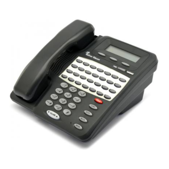
Page 43: Standard Model Telephone
Standard Model Telephone 2.15 The Emerald ICE Standard Model Telephone features 14 programmable Feature/DSS buttons (dual color LED), Headset Jack, 8 fixed feature keys (Mute, Speaker, Hold, Transfer, Conference, Feature, Volume Up, Volume Down), and one Status Bar type message waiting lamp. Figure 2-15 Emerald ICE Standard Model Telephone 2-18 Emerald ICE Installation & Hardware Reference Manual... -
Page 44: Dss (Direct Station Selection Terminal)
DSS (Direct Station Selection Terminal) 2.16 The DSS Console is a digitally interfaced component of the Emerald ICE. It connects to the system via any available digital port (610+2 Board/E or 12EKT digital port). The DSS is equipped with 40 Programmable Buttons. 12 of these buttons are intended for features code storage only and do not have LED indications associated with them. The 40 buttons are equipped with dual color LEDs and may be assigned any system Feature Code or Directory Number. (These buttons may be assigned for either system features operations or CO line access operations.) The DSS Console may be mounted in two positions (Lower Profile Desk Position and Wall Mounted Position). DSS Consoles are programmed to operate with an associated speakerphone. Speakerphones may be assigned up to 4 DSS Consoles each if required. The maximum DSS Consoles supported by the Emerald ICE is 12. Each equipped DSS Console requires one digital port therefore the total number (system capacity) of speakerphones possible is reduced by one for each DSS console installed. Figure 2-16 Deluxe Telphone with DSS Unit 2-19 Emerald ICE Installation & Hardware Reference Manual... -
Page 45: Expansion Boards
Expansion Boards 2.17 Integrated Voicemail ‐ 2 Voicemail cards are optionally available: The Emerald ICE Flash Voicemail card provides a feature‐rich, 8‐port voice processing system featuring 3 hours of message storage that is expandable to 9 hours. Capable of handling up to 64 voice mailboxes, the Flash Voicemail offers many of the professional features used by large corporations, such as Automated Attendant, Custom Call Routing, Password Protected mailboxes and an alert system to let employees know when a new voicemail has been received. The Emerald ICE HD Voicemail card provides a feature‐rich, 8‐port voice messaging system featuring 180 hours of message storage. Capable of handling up to 11,000 mailboxes, the HD Voicemail offers many of the professional features used by large corporations, such as Automated Attendant, Custom Call Routing, Dial‐by‐Name Directory, Password Protected mailboxes and an alert system to let employees know when a new voicemail has arrived. Refer to the Emerald ICE Flash Voicemail and Emerald ICE HD Voicemail Installation Manuals and User Guides for details on these voicemail options and their features. T1 PRI Board ‐ [Future Feature] VoIP Gateway Board ‐ [Future Feature] 2-20 Emerald ICE Installation & Hardware Reference Manual... -
Page 46: System Limits/Capacities
System Limits/Capacities 2.18 Time Slots: PCM ‐ 32 time slots x 4 Highways (128 voice channels) TDM 64 Time Slots (data processing) Customer Database memory protection 300 hours via on‐board lithium battery (no charging required) Ports: CO/PBX/Centrex Lines: ‐ 24 Digital Stations: ‐46 Standard Single Line Telephones: ‐ 18 DTMF Receivers: One dedicated per single line telephone port. DTMF Senders: Unlimited. (DTMF signal generation is derived from the core system tone resource. Tone combinations are available as needed.) Contacts: 1 LBC can be programmed as associated to a CO line, Music on Hold, or Paging or dialed by an extension to actuate the contact. Conference circuits: 8 ‐ 4 party conference circuits. DISA circuits: Any number of CO lines may be programmed for DISA operation. (4VAA required for operation.) System Attendants: 1 Attendant + 1 Alternate per Tenant Group Tenant Groups: 3 UCD/Hunt Groups: 24 Members per Group: 24 Group Types: UCD or Voice Announcer Hunting Method: Linear, All Ring or Distributed Voicemail Groups: 1 per Tenant (uses 1 UCD Group per VM system) Members (ports): 24 Integration Method: Digital Integrated Voice Systems and In‐band (for others) VM Message Waiting: + station number to turn VM button LED #*96 VM Control codes: + station number to turn VM button LED off. 2-21 Emerald ICE Installation & Hardware Reference Manual... - Page 47 Disconnect Digit(s): 8 digits max. Subscriber Calling via Intercom: 4 digits max. Transfers to VM : 4 digits max. Busy Forward: 4 digits max. No Answer Forward: 4 digits max. Direct Call Forward: 4 digits max. CO Line Recall: 4 digits max. CO Line Ringing: 4 digits max. UCD Overflow: 4 digits max. Record Digits for Voice Recorder function: 4 max. Delete Digits: 4 digits max. Suffix for transferred calls: 2 max. CO Line Loop Current sensing: Interrupt programmable from 50ms to 2500ms. Paging: 8 Internal Page Extension Groups; 1 External Page Port; 1 Internal All Call; 1 System (Internal/External) All Call; Speed Dialing: 1000 total bins, dynamically allocated. 200 bins at default allocated for system‐wide use. 20 bins at default allocated for extension use (extensions 401‐446 only) (50 possible per extension) 16 digits maximum per bin. Last Number Redial: 16 digits per station Save Number Redial: 16 digits per station User Saved Number (Memo Pad): 16 digits per station Callback request per station: 1 Camp On by a busy station: 1 Stations Camped on to a station: 1 Stations Camped on to a busy line: 1 Message ‐ Executive Notification: 6 preprogrammed;1 personal per station Message ‐ Executive Preprogrammed: 6 preprogrammed; 1 personal per station 2-22 Emerald ICE Installation & Hardware Reference Manual...
- Page 48 Message Waiting: 40 simultaneous maximum per system (does not affect VM message indications) Name in Display: 1 per station, 7 characters max. Class Of Service (COS): 8 (0‐7) per Day, 8 (0‐7) per Night Toll Restriction To/From Tables: 100 Tables per tenant, 10 digits per entry, Day and Evening COS assignable per entry per CO Line and Extension. Forced Verified Account Codes: 600 codes, 2‐8 digits max., each assigned a COS. Call Pick Up Groups: 8 Extension Groups. Station Lock Password: 4‐8 digits per extension. DB Programming Password: 8 digits (“________” at default). System Reminder Alarm: 8 time settings per Tenant Group. Station Alarm: 1 per station repeating or one time. Ring Schemes: 8 Distinctive Ring Tones: 8 per station. External Call Forward: Via Extension Call Forward settings. 2-23 Emerald ICE Installation & Hardware Reference Manual...
- Page 49 AC Power Source: Dedicated 117/230vac + 15%, 47‐63Hz single phase Power consumption: 1.5A maximum @ 120vac (180 watts) Power Supply Fuse: AC enter: 2A 250v DC output: 1A 125v Idle Channel Noise: ‐74 dB Cross Talk Attenuation: 75 dB (@ 1kHz) Ringing Sensitivity: 40v RMS 25 Hz Ringer Equivalence Number: 1.5 CO Line Signaling: DTMF amplitude (‐5 dB,‐7 dB) +‐ 2 dB, @ approx. 2 Vpp Pulse Dialing ratio 60/40 @ 10 PPS Music source / Background Music: 0 dBm at 600 ohm enter impedance; 1/8th inch phono jack Contact rating (Option Module LBC): 1A @ 30VDC; 0.5A @ 90VAC 30Hz; 1/8th inch phono jack External Page Port: 0 dBm at 600 ohms; 1/8th inch phono jack Environmental Data Operating Temperature: 0 to 40 C, 32 to 95 F Recommended Operating Temperature: 70 to 78 F Storage Temperature: 32 to 104 F Operating Relative Humidity: 5% to 90% (non‐condensing) Heat Dissipation (BTU): 300 2-24 Emerald ICE Installation & Hardware Reference Manual...
- Page 50 Wiring Data Deluxe/Standard Model Telephones (Distance measures in linear feet of cable from KSU to phone): 26 AWG ‐ 255m (850 ft.) 24 AWG ‐ 500m (1640 ft.) 22 AWG ‐ 700m (1983 ft.) Standard Single Line Telephone (Distance measures in linear feet of cable from KSU to SLT): 26 AWG ‐ 195m (650 ft.) 24 AWG ‐ 594m (1950 ft.) 22 AWG ‐ 476m (1586 ft.) Signaling Data DTMF Dialing mode: Frequency deviation: + 1% Rise time: 3ms Duration of DTMF signal: programmable 50‐150ms (70ms default) Inter‐digit time: programmable 50‐150ms (70ms default) VM Port DTMF duration: programmable 60‐150ms (120ms default) VM Port Inter‐digit time: programmable 60‐150ms (120ms default) Pulse Dialing mode: Pulse dial rate: 10 pulses per second Pulse Make/Break ratio: 60/40 2-25 Emerald ICE Installation & Hardware Reference Manual...
- Page 51 SLT bell follows ring cadence of Ring Scheme selected Distinctive 1 Distinctive 2 Distinctive 3 Distinctive 4 Frequency Cadence Intercom Ringing: Scheme 0 1 second On, 3 seconds Off Scheme 1 1 second On, 3 seconds Off Scheme 2 300ms On, 400ms Off, 300ms On, 4 seconds Off Scheme 3 follows ring cadence of Ring Scheme selected Scheme 4 follows ring cadence of Ring Scheme selected Scheme 5 follows ring cadence of Ring Scheme selected Scheme 6 follows ring cadence of Ring Scheme selected Scheme 7 ‐SLT bell‐ follows ring cadence of Ring Scheme selected Distinctive 1 Distinctive 2 Distinctive 3 Distinctive 4 Message Wait Callback: follows ring cadence of Ring Scheme selected 2-26 Emerald ICE Installation & Hardware Reference Manual...
-
Page 52: Configuration Flexibility
Configuration Flexibility 2.19 The Emerald ICE can be configured with single or dual cabinets. • Minimum (610+2): 6 CO lines + 10 digital +2 analog stations (single cabinet) • Maximum (1232): 12 CO lines + 22 stations + 10 SLT (single cabinet) ...or (1628): 12 CO lines + 4VoIP channels + 22 stations + 6 SLT (single cabinet) • Growth with second cabinet: can be expanded to (1840), including 18 CO lines + 22 stations + 18SLT..or (2464), including 24 CO lines + 46 stations + 18SLT ...or (2852), including 24 CO lines + 4 VoIP channels + 46 stations + 6 SLT ...or (4052), including 12 CO lines + 24 T1/PRI channels + 4 VoIP channels + 46 stations + 6 SLT Only one VoIP gateway is allowed in cabinet 1. • Only one 6CO board installation is allowed when T1/PRI is equipped in 2nd Cabinet. The following combinations with different configurations can be generated: 1. First cabinet ‐ Maximum: equipped with 7 boards (including VAA/IVM on CCB) CCB + (610+2)(6CO+10EKT+2SLT) + 6CO + 12EKT + 4SLT + 4SLT + VoIP gateway . 2-27 Emerald ICE Installation & Hardware Reference Manual... - Page 53 VoIP Gateway 6CO, Board (CO/Extension) (6CO) (4SLT) (4 Channels) 10EKT, (12EKT) 2SLT) 610+2 (Default) 1212 1216 1220 1224 1228 1232 1012 1016 1020 1024 1028 1032 1612 1616 1620 1624 1628 1632 2-28 Emerald ICE Installation & Hardware Reference Manual...
- Page 54 The IVM board can be substituted for the VAA card on the CCB for more user-friendly call administration. VoIP Gateway provides four more ports for the user to make VoIP calls through the Internet simultaneously. 2. Second Cabinet ‐ Maximum: equipped to use 6 boards (base board is included by default for PCB interconnection). Base + 6CO + 12EKT + 6CO + 12EKT ...or Base + 6CO + 12EKT + 6CO + 12 EKT + 4SLT + 4SLT ...or Base + T1/PRI + 12EKT + 12EKT ...or Base + T1/PRI + 6CO + 12EKT + 12EKT ...or Base + T1/PRI + 6CO + 12EKT + 12EKT+ 4SLT + 4SLT 2-29 Emerald ICE Installation & Hardware Reference Manual...
- Page 55 6CO Board 12EKT Board TI/PRI Board 4SLT Board Configurations (CO/Extension) (6CO) (12EKT) (24 Channels) (4 Analog) 12CO 4SLT 8SLT 12EKT 24EKT 1204 1208 1212 1216 1220 1224 1228 1232 24-Channels 2404 2408 2-30 Emerald ICE Installation & Hardware Reference Manual...
- Page 56 Configuration 6CO Board 12EKT Board TI/PRI Board 4SLT Board (CO/Extension) (6CO) (12EKT) (24 Channels) (4 Analog) 2412 2416 2420 2424 2428 2432 3004 3008 3012 3016 3020 3024 3028 3032 2-31 Emerald ICE Installation & Hardware Reference Manual...
-
Page 57: Power Consumption Table
0 @ On‐hook SLT phone set +0.9 @ Ringing ‐ Power consumption of KSU 1 +1.5 (610+2/B) ‐ board +3 (CC/B) KSU 1 & 2 +0.8 ‐ (4SLT/B, 6CO/B 12EKT) Power consumption of KSU 1 +2 ‐ Voice mail card (Flash version) Power consumption of KSU 1 +6 ‐ Voice mail card (HD version) Example: Full Load system configuration with 22 EKT phone sets and 8 SLT phone sets the power consumption at the AC line is 15(KSU1)+3.2(4SLTx2, 6CO, 12EKT) + 4(EKTx22)+12(SLTx8) = 74.2W (max). 2-32 Emerald ICE Installation & Hardware Reference Manual... -
Page 58: Installation
1. Plan the installation, including the Key Service Unit (KSU1 & KSU2) and Main Distribution Frame (MDF) location, MDF, Electronic Key Telephone (EKT) station locations, Direct Station Selection (DSS) console locations, station cable runs, and optional equipment. 2. Prepare the correct tools and supplies. (UTP telephony grade cable/wiring. Miscellaneous telephony hardware; 66M1‐50 blocks, modular jacks, etc.) 3. Run Emerald ICE extension cable/wiring for EKT, DSS consoles and analog devices (FAX machines, modems, etc.) from the MDF to each location. (Wiring topology is referred to as “star‐wiring” or “home‐run” configuration; no cable should loop from one telephone location to another.) 4. Run cable/wiring to any optional equipment, such as external paging equipment, loud bell signaling devices, music sources, etc. 5. Mount the MDF backboard and attach the “punch‐down” (66) terminal block(s) on the backboard. This documentation adheres to traditional installation practices of telephony equipment using a dedicated MDF with 66 block wiring field to promote full serviceability of the system and connections using proven techniques. 6. Terminate extension cables on modular jack assemblies at the terminal locations. 7. Mount the KSU(S) on the MDF backboard. Mounting template provided. 8. Ground KSU1 (and KSU2 if equipped) to a known “good” earth ground. Emerald ICE Installation, Programming & Maintenance Manual... - Page 59 Using Bridging Clips on station port wiring is not recommended since this introduces a connection point that is not required. Service for any one extension can be actuated via the jumper wire of that extension without affecting any other station/extension ports/EKTs. 14. Install the terminal instruments (EKTs and DSSs) and any optional terminal equipment, such as Door Phones or analog devices. Emerald ICE Installation, Programming & Maintenance Manual...
-
Page 60: Site Planning
(A computer with a hard disk drive.) This equipment cannot function in environments above 95 degrees Fahrenheit ambient temperature. The MDF should consist of a 3/4‐inch plywood TMB (Telephone Mounting Board) large enough to mount all hardware and equipment allowing all components ample space for adequate ventilation and servicing. Allow additional room for external apparatus, if used. For cooling purposes, ample air space of 10cm (4”) at the top, bottom, left and right sides should be provided for each KSU. Emerald ICE Installation, Programming & Maintenance Manual... - Page 61 • Never touch non‐insulated telephone wires or terminals unless the tele‐ phone line has been disconnected at the network’s interface. • Use caution when installing or modifying telephone lines. Tools and Supplies • Assemble the correct supplies and tools to install the Emerald ICE as it is intended. • Use UTP (Unshielded, Twisted‐Pair) three or four pair cable to run from the MDF (Main Distribution Frame) to all station terminals (EKT, DSS Consoles and analog devices). • Digital terminals only need one twisted pair to operate. (Additional pairs are always recommended to allow for future potential uses e.g. Facsimile machines and modems.) • Six conductor modular jack assemblies for all station terminals. • Standard punch‐down terminal block(s) (66Ml‐50 type) as required. • Twenty‐five (25) pair UTP cable fitted with male gender AMP‐type connec‐ tors at one end (typically referred to as “pig‐tails”). The quantity of these cables is determined by the equipment installed. The basic configuration requires two 25‐pair cables. • AC voltage surge/spike protector. • Standard telephone hand tools and mounting hardware for the KSU(s), MDF backboard, punch‐down terminal block(s), modular jack assemblies, etc. Emerald ICE Installation, Programming & Maintenance Manual...
- Page 62 4. Locate a suitable, known‐good earth ground preferably within 10 feet of the MDF and route a #10 AWG grounding wiring from the point of grounding to the MDF for connection to the KSU. (See photo example.) Install all terminal device wiring (telephone cabling) and route to the MDF location for termination. 5. Mount all equipment and termination hardware as required to complete interconnection of terminal devices and KSU ports. KSU Components and Installation The Key Service Units (KSU) are shipped in their own protective master carton and contain the following components: KSU1 • 1 Mounting Template • 1 System Installation & Maintenance Manual (this book) • 1 Documentation and RMP Installer CD • 1 Pocket Guide • Standard 610+2 Board equipped with 6 CO Line ports 10 digital extension ports and two analog device ports . • Device ports/Door Phone relays and 1 CO Line Power Failure Port. • Standard CCB (Central Control Board) • 1 hardware packet Emerald ICE Installation, Programming & Maintenance Manual...
- Page 63 KSU2 • 1 mounting template • 1 Expansion Cabinet equipped with Base Board • 1 hardware packet Open the carton(s) and verify that all items are complete and undamaged. Remove all packing material and store for future use in the event that return shipment is required. Mounting the KSU Follow these instructions to mount the KSU. 1. Select a suitable location for the KSU1 considering that the expansion (KSU2) may be installed at the same time or sometime in the future. KSU1 and KSU2 may be mounted such that they are side‐by‐side or mounted one above the other. The ventilation and mounting provisions of each KSU allow them to be mounted horizontally or vertically. Refer to the pictures for examples of how the KSU(s) may be mounted. Emerald ICE Installation, Programming & Maintenance Manual...
- Page 64 2. Using the mounting template as a guide, mark the two (2) mounting screws locations on the TMB for he mounting position preferred. 3. Pre‐drill two (2) screw holes and install the two, pan‐head No. 10 screws (supplied) into the backboard with a screwdriver. The screw heads should protrude about 2cm from the backboard plywood surface. Emerald ICE Installation, Programming & Maintenance Manual...
- Page 65 KSUI and KSU2 are intended to be wall mounted only. Mount each KSU using the slotted mounting holes as they were intended to assure compliance with this important heat-dissipation requirement. Ground the KSU. Extend Earth Ground into the KSU(s) using #10AWG wire. Terminate the grounding wire onto the ground lug provided there. A “known good” earth ground must be connected. Examples of good earth grounds are: Emerald ICE Installation, Programming & Maintenance Manual...
- Page 66 Power Consumption of Components Installed in the Specifications section to determine the required battery supply necessary to maintain system functionality for the duration desired at this site. Use the following to install System Back‐Up Batteries: The battery charging board is mounted at the Power Supply voltage regulator Danger of explosion if battery is incorrectly replaced! Replace only with the equivalent type recommended by the manufacture. Dispose of used batteries according to the battery manufacturer's instructions. Emerald ICE Installation, Programming & Maintenance Manual...
- Page 67 MDF (Main Distribution Frame) The various ports of the Emerald ICE are extended to the MDF using industry standard 4, 12, and 25 pair UTP (Unshielded Twisted Pair) cable. Inside the KSU pairs are terminated using screw terminal posts, modular ended crimping connectors and AMP‐type Male gender connectors. These cables are then routed out of the KSU to the 66M1‐50 blocks for termination and jumper‐wiring there. The installer has choices when completing these connections and it is left to the installer’s discretion to use the most suitable industry standard wiring practice for the particular installation. In the examples of this manual, standard 66M1‐50 connectors are used. The following example illustrates a two‐cabinet installation with the KSUs mounted vertically and side by side. MDF cables are routed out of the KSU through the opening in the corner of the KSU housing. A cable restraint clamp is provided and may be used to secure cables at that point. 3-10 Emerald ICE Installation, Programming & Maintenance Manual...
- Page 68 Important! Replace the Removable Access Panel after all connections have been made. The panel is required to be in position to comply with FCC regulations. The 66Ml‐50 is split into a left half and right half for wiring terminations. Each row is conductive between the left two columns and the right two columns. This is the source of the term “Split 50.” Terminate cable pairs from the KSU and from telephone locations on outer column pins, one lead only per pin. NEVER terminate two wires on one pin! This is referred to as “double‐punching” and causes poor connection of wires on the terminal. 3-11 Emerald ICE Installation, Programming & Maintenance Manual...
- Page 69 66M1-50 Pinouts Emerald ICE boards equipped with 25 pair AMP‐type cable connectors are: • KSU1 610+2 Board • 12EKT • KSU2 Base Board Refer to the charts on the following pages for pinout designations per cable pair for each board type and associated connector. 3-12 Emerald ICE Installation, Programming & Maintenance Manual...
- Page 70 3-13 Emerald ICE Installation, Programming & Maintenance Manual...
- Page 71 3-14 Emerald ICE Installation, Programming & Maintenance Manual...
-
Page 72: Rmp Installation
RMP Installation The RMP is a Microsoft® Windows® based application that utilizes checkboxes, drop down lists and selection lists to program the various features. The RMP application is included with the Documentation CD and RMP Installer supplied with the KSU. Insert the CD into a PC and a menu of selections will be generated. The CDʹs autorun feature will display a menu of choices. These include documentation, DESI Labels and the RMP Installer. Autorun CD Selections Click to Install RMP Click on the RMP Installer button as shown and follow the prompts to install the application onto your PC. 3-15 Emerald ICE Installation, Programming & Maintenance Manual... - Page 73 Your PC must be connected with the Emerald ICE via a Straight 9‐Pin Connector Cable which connects on the top of the CCB Board to a COM port on your PC. COM Port After installing the RMP application and connecting your PC with the KSU, you are now ready to initialize your system. 3-16 Emerald ICE Installation, Programming & Maintenance Manual...
-
Page 74: Ksu Initialization Procedure
KSU Initialization Procedure 1. Verify that the KSU power is OFF. 2. Verify that the jumper pins on JP7 are in the ʺColdʺ position. 3. Power up the KSU and wait 10 seconds. 4. Power down the KSU and move the JP7 pins to the ʺNormalʺ position. 3-17 Emerald ICE Installation, Programming & Maintenance Manual... - Page 75 If kSU1 is powered on and KSU2 is not while cabling is connected between the two cabinets, system malfunctions will occur. 6. Verify that the telephones have been initialized. A date/time display will be visible on the Deluxe Telephones. For a Standard telephone, a dial tone will be heard. 7. Enter the RMP programming mode and select RP, Remote Control, and perform a Software Cold Start. It should be approximately 30 seconds before a display is visible on the Deluxe Telephones or a Dial Tone is heard on a Standard Telephone. 8. When a display is visible on the Deluxe Telephones or a Dial Tone is heard on a Standard Telephone, power down the KSU, wait 15 seconds, and then power up the KSU again. 3-18 Emerald ICE Installation, Programming & Maintenance Manual...
- Page 76 9. Observe the System Status LED on each KSU next to the power switch. This LED follows LED DA2 on the CCB (Central Control Board) and indicates the status of the main system processor. During the first power‐up sequence (Cold‐Start strap moved to “Normal” position), default data (factory program) is loaded. A series of flash rates occur during this process. When default is successfully loaded or whenever the system becomes functional following a power failure, the CCB Heart‐beat LED and System Status LED maintains a consistent fast flash rate. 3-19 Emerald ICE Installation, Programming & Maintenance Manual...
- Page 77 3-20 Emerald ICE Installation, Programming & Maintenance Manual...
-
Page 78: Basic Programming
Basic Programming General Programming the Emerald ICE for the various features is executed using a Deluxe Model Telephone or the RMP (Remote & Maintenance Programming) application on a PC. Programming with a Deluxe Model Telephone is accomplished using a specifically applied series of key entries used in conjunction with the digital telephone display. Programming using the RMP is accomplished using the Microsoft Windows based application to program with check boxes, drop down selection lists and fill in entries. Emerald ICE Installation, Programming & Maintenance Manual... -
Page 79: Deluxe Telephone Programming Access
Deluxe Telephone Programming Access Emerald ICE programming using the Deluxe Telephone set begins by accessing the programming database. Follow the procedures outlined in the illustration below to access the Emerald ICE Deluxe telephone programming features. Once the password has been authenticated, you can begin programming. Figure 4-1 Deluxe Telephone Programming Access Emerald ICE Installation, Programming & Maintenance Manual... - Page 80 Number and Programming Type Index Number Type of Programming Extension Programming Trunkline Programming Call Handling Programming System Resource Programming Restriction Programming Extension Application Programming CO Line Application Programming System Application Programming Programming menus are organized similarly to those of the RMP which is discussed herein. Emerald ICE Installation, Programming & Maintenance Manual...
- Page 81 About the RMP The RMP or Remote & Maintenance Programming application is a Windows‐based application used to program a database with specific, programmable Emerald ICE features, loaded onto the system and executed in conjunction with the system software. The application features easy‐to‐use submenus featuring check boxes, drop down lists, radio buttons and convenient text fields used to program the various Emerald ICE screens resident on the application. These screens are described briefly within the following subsections with specific programming instructions provided in the following chapters of this manual. All programming screens are accessed from the RMP Main Menu as shown below Figure 4-2 in Figure 4-2 Main Title Bar Menu Menu Bar Display Area Client Window Status Bars KSU Software Version Emerald ICE Installation, Programming & Maintenance Manual...
- Page 82 RMP‘s Main Window contains five areas: • Title bar • Menu bar • Client Window • Status Bars A brief description of the functionality of each component is provided below, whereas the detailed specification of the functions of the RMP will be described in the chapters herein. Title Bar The Main Window’s Title Bar displays “Remote Maintenance & Programming ‐ Untitled” if the RMP is invoked without a file name. The active file name will replace “Untitled” once it has been saved and given a new name. When the application is run, it opens a new document, therefore “Untitled” is displayed. If the user opens an existing database, the database name will replace “Untitled” in the title bar. Menu Bar This is where users perform most of the functions provided by the RMP. Clicking on a menu item will pull down a menu list. In several cases the menu selection could have sub‐menus. Client Window The only purpose of the Client Window is to display the logo and the version information. Status Bars Two Status Bars are provided to present the real‐time status of RMP. The upper part is Communication Port Status Bar, and the other is Message Status Bar. Emerald ICE Installation, Programming & Maintenance Manual...
- Page 83 The top of each of the programming screen windows that are accessed from Main Menu display the route and title of each of the submenus. Figure 4-3 The RMP Main Menu tree with the main submenus is shown below in Figure 4-3 Menu Hierarchy RMP Main Menu File Control Remote Programming (RP) Remote Maintenance (RM) The main programming submenus are accessed from either the Remote Programming (RP) group or the Remote Maintenance (RM) group. The File and Control groups are used mainly for administrative purposes including saving or opening databases, converting databases, connecting with the Emerald ICE System from a PC and setting the system time. Emerald ICE Installation, Programming & Maintenance Manual...
- Page 84 Remote Programming Screens Subgroup (RP) The Remote Programming subgroup of programming screens features access to all of the non‐Maintenance related programming. These programming screens are Figure 4-4 shown below in Basic descriptions and general usage for each of the subscreens shown below are provided in the subsections herein. The specific programming instructions are provided within each of the following chapters. Figure 4-4 Remote Programming Subgroup of Programming Screens Remote Programming (RP) Extension C.O. Line Call Handling Resource Toll Restriction Extension Application C.O. Line Application System Application Feature Key Programming Emerald ICE Installation, Programming & Maintenance Manual...
- Page 85 Remote Maintenance Programming Screens (RM) Subgroup The Remote Maintenance Programming Screens (RM) subgroup. This features programming screens used in programming all of the maintenance features of the Figure 4-5 Emerald ICE . These programming screens are shown below in . Basic descriptions and general usage for each of the subscreens shown below are provided in the separate subsections herein. The specific programming instructions are provided within each of the following chapters. Figure 4-5 Remote Maintenance Programming Screens Remote Maintenance (RM) (RM) Configuration Diagnostics Status HW/SW Revision Event Logon Data Remote Control Emerald ICE Installation, Programming & Maintenance Manual...
-
Page 86: Accessing And Sending Modifications To The Rmp
. 2. Open an existing database or enter a file name to create a new database. 3. Select Connect on the RMP Menu Bar. A Password entry screen will appear as shown below: 4. Enter a password in the diaglogue box and click the OK button. (The default password is 8 spaces.) The following will be dislayed: Local Connection 5. With the Local tab selected, connection with a local pc via serial cable is possible. Verify the COM Port and use the dropdown list to select. Verify the Baud Rate: of the connection and use the dropdown list to select. Click on the OK button to connect to the Emerald ICE . Emerald ICE Installation, Programming & Maintenance Manual... - Page 87 8. Select a Baud Rate for communications using the Baud Rate drop‐down list. 9. Enter a 10‐digit Modem Telephone Number in the Number field. 10. Click on the Add to List button and the modem information will be displayed in the Display Area of the window. 11. Repeat steps 7 through 9 to add additional modems. 12. To connect with the RMP , click on the Connect button. A connect‐progress window will be displayed as shown below. The connect process will time‐out in 10 seconds if a connection is not established. If a connection cannot be made after a second attempt, repeat these procedures from step 5, verifying Modem Type, Modem Initial String and Baud Rate . 4-10 Emerald ICE Installation, Programming & Maintenance Manual...
- Page 88 Sending Modifications to the Database 1. After clicking on Exit , the RMP will prompt you to save your changes to the Database. Press N to abort changes and leave all data unchanged or Y to save changes. If you selected Y for yes, you will then be prompted “File Exists, Override?” If you select N for no, you will abort the changes and leave all of the existing data unchanged. 2. Continue making other programming changes or exit the RMP . 4-11 Emerald ICE Installation, Programming & Maintenance Manual...
- Page 89 4-12 Emerald ICE Installation, Programming & Maintenance Manual...
-
Page 90: Phone Extension Programming (01)
Feature/DSS button on the Deluxe Telephone to be used with the Auto Record feature. Outgoing call recording begins after the Call Duration Timer has expired. Placing a call on hold constitutes completing a call and ends the recording function. If the recorded conversation prior to pressing hold is to be kept, the Voice Record Feature/DSS button must be pressed prior to pressing Hold ( Auto Record and Voice Record occupy one voice channel on the Emerald ICE system during the record operation. This resource consuming function should be deployed with careful consideration of the total available voice mail channels and the overall impact on other voice mail/auto attendant related functions. Only eight (8) Deluxe Telephones may be assigned for use with the Auto Record feature. Default Settings: Auto Record is disabled at default for all extensions. Emerald ICE Installation, Programming & Maintenance Manual... - Page 91 RECORD ALLOW programming screen for the selected extension. The display will show the current setting for Record Allow for this extension. 3. Press the softkey beneath chg to select Y/N (Yes/No). Y will set this extension as a Record Allow extension. 4. Press the Volume button ( ) to return the DB Item Select Screen. 5, Repeat steps 2 through 4 for other extensions. RMP Programming 1. Access the RMP using the procedures described in Section 3.3. 2. Select RP, Extension from the toolbar to display the following window. Emerald ICE Installation, Programming & Maintenance Manual...
-
Page 92: Call Forward- Extension
Description There are several Extension Call Forward choices: • All – Forward all of your calls. • Busy – Forward your calls when your telephone is busy. • Follow Me – Forward calls at your extension to the extension where you are currently working (conference room, associates office, etc.) • Follow Preset – Invoke call forward at your extension so that it can be changed from another extension. • No Answer – Forward your calls in no answer conditions. • External – Forward your calls to another location or different telephone number. (This feature must be enabled for your extension in database admin‐ istration.) Forward conditions may be set as follows for each call forward type: • Intercom calls only • Intercom and CO Line (including transferred CO Lines) calls • CO Line calls only Emerald ICE Installation, Programming & Maintenance Manual... - Page 93 ALWAYS , NEVER , DAY , or NIGHT . 8. Press the softkey beneath next to advance to the TALK TIME programming screen. 9. Press the softkey beneath chg until the desired value displays. Available talk times can be 1 ‐ 5 , 10 or 15 minutes. 10. Press the Volume button ( ) to return to the DB Item Select Screen . Emerald ICE Installation, Programming & Maintenance Manual...
- Page 94 1. Access the RMP using the procedures described in Section 3.3. 2. Select RP, Extension from the toolbar to display the following window. Program the extension with the ability to use External Call Forward: 1. Using the drop‐down list in the Extension field select an extension to program. 2. Click on the ECF Operation checkbox to to enable or disable the External Call Forward features for the extension selected. 3. Click on the Update button, follow the prompts and repeat steps 1 through 3 for other extensions, as necessary. 4. Continue other programming or click on the Close button to close the window without making changes or click on the Update button and follow the prompts to save the database changes. Emerald ICE Installation, Programming & Maintenance Manual...
- Page 95 3. Using the drop‐down lists for Service: and Talk Time: in the External Call FWD section of the programming window, select the service mode for when you would like the External Call Forwarding programming to be active. Selections can be Always, Never, Day , or Night . 4. Select the allowable External Call Forwarding talk times using the drop‐down list in the Talk Time field. Available selections can be 1‐5, 10 or 15 minutes. 5. Continue other programming or click on the Close button to close the window without making changes or click on the Update button and follow the prompts to save the database changes. Emerald ICE Installation, Programming & Maintenance Manual...
-
Page 96: Class Of Service - Extension
2. Enter 01- Extension No. -05 and press the softkey beneath save to advance to the DAY CLASS programming screen to program the extension’s Day COS. (0‐7.) Or… 3. Enter 01- Extension No. -05 and press the softkey beneath save to advance to the NIGHT CLASS programming screen to program the extension’s Night COS. (0‐7.) 4. Press the softkey beneath chg to change either the DAY or NIGHT COS until the desired COS displays. Emerald ICE Installation, Programming & Maintenance Manual... - Page 97 2. Select RP, Extension from the toolbar to display the following window. 3. Using the drop‐down list in the Extension field, select an extension to program. 4. Using the drop‐down lists in the Day Class and Evening Class fields, select a Day Class: COS and/or an Evening Class: COS for the Extension selected using the drop down lists in the respective fields. 5. Click on the Update button, follow the prompts and repeat steps 3 through 5 for other extensions, as necessary. 6. Continue other programming or click on the Close button to close the window without making changes or click on the Update button and follow the prompts to save the database changes. Emerald ICE Installation, Programming & Maintenance Manual...
-
Page 98: Co Line Assignment
3. Toggle the softkey beneath chg for Y/N. Selecting Y will allow access on the CO line. 4. Press the Volume button ( ) to return to the DB Item Select screen and enter another extension and CO Line. Or… 6. Press the softkey beneath back or the softkey beneath next to select the previous or next sequential CO Line for the selected extension. 7. Press the softkey beneath chg until the desired values are displayed. 8. When finished programming CO Line Access, press the Volume button ) to return to the DB Item Select Screen or exit programming. Emerald ICE Installation, Programming & Maintenance Manual... - Page 99 1. Access the RMP using the procedures described in Section 3.3. 2. Select RP, Extension from the toolbar to display the following window. Program CO Line Access: 3. Using the drop‐down list in the Extension field, select an extension to program. 4. In the Line Access Assignment field, double‐click the CO line extensions so that a Y is visible next to the line number for each line required for the extension seleted. 5. Click on the Update button, follow the prompts and repeat steps 3 through 5 for other extensions, as necessary. 6. Continue other programming or click on the Close button to close the window without making changes or click on the Update button and follow the prompts to save the database changes. 5-10 Emerald ICE Installation, Programming & Maintenance Manual...
-
Page 100: Co Line Receive Assignment
‐ TRK CO TNT programming screens for the extension and CO Line selected. 4. Toggle the softkey beneath chg for Y/N.Y will allow the specified extension to answer CO lines when ringing. 5. Press the softkey beneath back or the softkey beneath next to go to the previous or advance to the next CO Line to program for this extension. Or… 6. Press the Volume button ( ) to return to the DB Item Select Screen and enter the next extension/CO Line to program. 7. When all changes are complete, press the Volume button ( ) to return to the DB Item Select screen or exit programming. 5-11 Emerald ICE Installation, Programming & Maintenance Manual... - Page 101 1. Access the RMP using the procedures described in Section 3.3. 2. Select RP, Extension from the toolbar to display the following window. 3. Ussing the drop‐down list in the Extension field, select an extension to program. 4. In the Receive Assignment field, double‐click the CO line extensions that will be available for pickup by the extension selected so that a Y is visible next to the line number for each line selected. 5. Click on the Update button, follow the prompts and repeat steps 3 through 5 for other extensions, as necessary. 6. Continue other programming or click on the Close button to close the window without making changes or click on the Update button and follow the prompts to save the database changes. 5-12 Emerald ICE Installation, Programming & Maintenance Manual...
-
Page 102: Extension Paging Groups
System Application – Numbering Plan – EXT Page Group = 400‐408 Deluxe Telephone Programming 1. Access the Deluxe Telephone Programming Features as described in Section 3.2 2. enter 01- Extension No. -04 , then press the softkey beneath save to advance to the PAGING GROUP programming screen. 4. Press the softkey beneath chg until the Paging Group for the selected extension displays. 5. Press the button to return to the previous menu level or press the Volume button ( ) to return to the DB Item Selection Screen or exit programming. 5-13 Emerald ICE Installation, Programming & Maintenance Manual... - Page 103 1. Access the RMP using the procedures described in Section 3.3. 2. Select RP, Extension from the toolbar to display the following window. 3. Using the drop‐down list in the Extension field select an extension to program. 4. Using the drop‐down list in the Paging Group: field, select a paging group for which you would like the selected extension to be a part of. 5. Click on the Update button, follow the prompts and repeat steps 3 through 5 for other extensions, as necessary. 6. Continue other programming or click on the Close button to close the window without making changes or click on the Update button and follow the prompts to save the database changes. 5-14 Emerald ICE Installation, Programming & Maintenance Manual...
-
Page 104: Extension Pick Up Groups
PICKUP GROUP programming screen for the selected extension. 3. Press the softkey beneath chg until the desired pickup group displays. To continue programming Pick Up Groups for other extensions: 4. Press the Hold ( ) button to exit programming for this extension and enter a new extension. 5. Press the softkey beneath show . 6. Press the softkey beneath next until the database item Pick Up Group displays for this extension. Or… 7. Press the Volume button ( ) to return to the DB Item Select Screen and enter the extension number and the Pick Up Group item number ( 03 ). 8. Continue making other programming changes or exit the programming mode. 5-15 Emerald ICE Installation, Programming & Maintenance Manual... - Page 105 1. Access the RMP using the procedures described in Section 3.3. 2. Select RP, Extension from the toolbar to display the following window. 3. Using the drop‐down list in the Extension field, select an extension to program. 4. Using the drop‐down list in the Pickup Group: field, select a Pick Up Group for which you would like the selected extension to be a part of. 5. Click on the Update button, follow the prompts and repeat steps 3 through 5 for other extensions, as necessary. 6. Continue other programming or click on the Close button to close the window without making changes or click on the Update button and follow the prompts to save the database changes. 5-16 Emerald ICE Installation, Programming & Maintenance Manual...
-
Page 106: Extension Swapping
2. enter 01- Extension No. -22 , then press the softkey beneath save . This advances to the DIR NO. SWAPPING programming screen. 3. Press the softkey beneath show . 4. Enter the extension directory number that is to be assigned to this port, then press the softkey beneath save . The new directory number is now in operation on this port. The old directory number is now moved to the port where the new number came from. 5. Press the Hold button ( ) to return to the previous menu level or press the Volume button ( ) to return to the DB Item Selection Screen or exit programming. 5-17 Emerald ICE Installation, Programming & Maintenance Manual... - Page 107 4. Using the drop‐down list in the DIR No. Swapping field, select a new directory number for this extension. If this directory number was in use at another extension port, that port is immediately reassigned the directory number previously assigned to the port where the swap was invoked. The directory number must be a valid Extension Directory Number as allocated in System Applications – Numbering Plan 2. 5. Click on the Update button, follow the prompts and repeat steps 3 through 5 for other extensions, as necessary. 5-18 Emerald ICE Installation, Programming & Maintenance Manual...
-
Page 108: Feature Button Disable
Extension – ftr btn Disable is set to N . (Range is: Y/N .) Deluxe Telephone Programming 1. Access the Deluxe Telephone Programming Features as described in Section 3.2 2. Enter 01- Extension No. -16 , then press the softkey beneath show to advance to the FEATURE BTN programming screen. 3. Press the softkey beneath chg until the appropriate value displays for the selected extension (401‐476). 4. Press the Hold button ( ) to return to the previous menu level or press the Volume button ( ) to return to the DB Item Selection Screen or exit programming. 5-19 Emerald ICE Installation, Programming & Maintenance Manual... - Page 109 RMP Programming 1. Access the RMP using the procedures described in Section 3.3. 2. Select RP, Extension from the toolbar to display the following window. 3. Using the drop‐down list in the Extension field, select an Extension . 4. Enable or disable feature button usage by clicking the checkbox in the Feature Button Disable: field. 5. Click on the Update button, follow the prompts and repeat steps 3 through 5 for other extensions, as necessary. 6. Continue other programming or click on the Close button to close the window without making changes or click on the Update button and follow the prompts to save the database changes. 5-20 Emerald ICE Installation, Programming & Maintenance Manual...
-
Page 110: Intrusion - Extension/Co Line
2. Enter 01- Extension No. -11 to advance to the INTRUS. ACTIVE programming screen. 3. Toggle the softkey beneath chg to select Y / N . Y will allow an initial caller to enter into an existing conversation. 4. Press the to return to the Data Base Item Selection Screen. 5. Repeat steps 2 through 4 for other extensions. 6. Press the button to return to the previous menu level or press the to return to the Data Base Item Selection Screen or exit programming. 5-21 Emerald ICE Installation, Programming & Maintenance Manual... - Page 111 RMP Programming 1. Access the RMP using the procedures described in Section 3.3 . 2. Select RP, Extension from the toolbar to display the following window. 3. Click on the Intrusion Active check box for the extension to be changed. 4. Click on the Intrusion Accept checkbox for the Extension to be changed. 5. Click on the Intrusion Tone checkbox for the Extension to be changed. 6. Continue other programming or click on the Close button to close the window without making changes or click on the Update button and follow the prompts to save the database changes. 5-22 Emerald ICE Installation, Programming & Maintenance Manual...
-
Page 112: Monitor-Extension-Co Line
3. Press the softkey beneath chg until the appropriate MONITOR CLASS for this extension displays. MONITOR CLASS specifies who can Monitor this extension and who can this extension Monitor. 0 = Most Privileged, 9 = Least Privileged. To Monitor another extension this extension must be more Privileged. 4. Press the to return to the Data Base Item Selection Screen 5. Repeat steps 2 through 4 for other extensions. 6. Press the button to return to the previous menu level or press the to return to the Data Base Item Selection Screen or exit programming. 5-23 Emerald ICE Installation, Programming & Maintenance Manual... - Page 113 2. Select RP, Extension from the toolbar to display the following window. 3. Using the drop‐down list in the Extension field, select an extension to program. 4. Select the Monitor Class from the drop down list. Monitor Class specifies who can Monitor this extension and who can this extension Monitor. 0 = Most Privileged, 9 = Least Privileged. To Monitor another extension this extension must be more Privileged. 5. Click on the Update button, follow the prompts and repeat steps 3 through 5 for other extensions. 6. Continue other programming or click on the Close button to close the window without making changes or click on the Update button and follow the prompts to save the database changes. 5-24 Emerald ICE Installation, Programming & Maintenance Manual...
-
Page 114: Paging
• All Call Paging ‐ to access all paging zones (internal and external). Paging is one‐way only. The Page Allow/Deny setting does not interfere with an extension’s ability to make a page or to establish a Meet Me page. In a Paging Group, extensions may receive announcements to particular Internal Paging Zones based in this setting. Default Settings: Extension – Paging Group = 1 for all extensions. (Range is 1‐8.) Extension – Paging Allow = Y for all extensions. (Range is Y/N.) System Resource – External Pager – Tenant Group = 1. (Range is 1‐3.) System Resource – External Pager – Paging Group 1 = Y. (Range is Y/N.) System Application – Ext Page Group assigns codes 400‐408. System Application – Ext Pager assigns code 777. 5-25 Emerald ICE Installation, Programming & Maintenance Manual... - Page 115 7. Press the softkey beneath chg until the desired TENANT GROUP displays. This is the tenant group to which the external pager will be associated. 8. Press the softkey beneath next until the PAGING_GP to be programmed displays. 9. Toggle the softkey beneath chg for Y/N for each of the Paging Groups. Y will allow the External Pager to be connected for page announcements whenever the selected Page Group is dialed. 10. Press the button to return to the previous menu level or press the to return to the Data Base Item Selection Screen or exit programming. 5-26 Emerald ICE Installation, Programming & Maintenance Manual...
- Page 116 RMP Programming 1. Access the RMP using the procedures described in Section 3.3 on page 3‐6 . 2. Select RP, Extension from the toolbar to display the following window. Program extensions into Paging Groups: 3. Select an Extension from the drop down list and assign a Paging Group from the drop down list. 4. Click on the Update button, follow the prompts and repeat step 3 for other extensions. 5-27 Emerald ICE Installation, Programming & Maintenance Manual...
- Page 117 Program External Pager to a Tenant Group and Paging Groups: 5. Select RP, Resource, External Page Port from the toolbar to display the following window. This window is used to assign the page ports to a tenant group and to include them in one or more paging groups. 6. Selecting the Tenant from the drop down list to set the values of the Paging Groups below. 7. Continue other programming or click on the Close button to close the window without making changes or click on the Update button and follow the prompts to save the database changes. 5-28 Emerald ICE Installation, Programming & Maintenance Manual...
-
Page 118: Recorded Announcement Device
A typical RAD message is, “Please continue to hold. Your call will be handled in the order in which it was received.” The significant advantage of these announcements is the software control of callers waiting in queue for a UCD Agent to become available. A caller can be played messages to assure them that they are still in queue and not forgotten while the system maintains the queue priority. The Emerald ICE enhances this function significantly through the use of integrated RAD messages as part of the voice mail implementation. Whenever the optional Emerald ICE HD Voice Mail is installed into the system platform, RAD announcement space is allocated for each of the UCD Group Overflow and Re‐route Destinations. This significantly reduces the cost and complexity of applying this function to UCD operation. When analog RAD devices are used, multiple queued callers will stack in queue for message playback. When the analog port is available to handle another call the next call in RAD queue hears the recorded message. When multiple analog RAD devices are required to handle high call traffic, these RAD devices (with the same recording) can be placed into a UCD Group set for Attribute “V.A.” When this is done, the Overflow Destinations and Reroute Destinations are programmed for that UCD Group number, (not the individual analog port numbers connected to the RAD devices. UCD queued callers who are routed to Overflow Destination – RAD devices remain in UCD queue. When a UCD Agent answers the queued – ringing call, the call is removed from UCD queue and connected to the UCD Agent. If a UCD queued caller is listening to a RAD message when the Agent answers the UCD call, that call is diverted immediately to the UCD Agent and the RAD device port is released. 5-29 Emerald ICE Installation, Programming & Maintenance Manual... - Page 119 . 6. Press the softkey beneath next until the PORT TYPE screen displays. 7. Press the softkey beneath chg until the appropriate PORT TYPE displays. Or... 8. Press the Volume button ( ) to return to the DB Item Select Screen. 9. Repeat steps 2 through 9 for all extensions to be programmed as Port Type 10. Press the Hold button ( ) to return to the previous menu level or press the Volume button ( ) to return to the DB Item Selection Screen or exit programming. 5-30 Emerald ICE Installation, Programming & Maintenance Manual...
- Page 120 1. Access the RMP using the procedures described in Section 3.3 . 2. Select RP, Extension from the toolbar to display the following window. 3. Using the drop‐down list in the Extension field, select an extension to program. 4. Using the drop‐down list in the Port Type: field, select VA as the Port Type for the Extension selected. 5. Click on the Update button, follow the prompts and repeat steps 3 through 5 for other extensions. 6. Continue other programming or click on the Close button to close the window without making changes or click on the Update button and follow the prompts to save the database changes. 5-31 Emerald ICE Installation, Programming & Maintenance Manual...
-
Page 121: Station Message Detail Recording (Smdr)
2. Enter 01- Extension No. -19 , then press the softkey beneath save . This advances to the SMDR OUTPUT programming screen for the extension selected. 3. Toggle the softkey beneath chg for Y/N . Y will enable SMDR output for the selected extension. 4. Press the Volume button ( ) and repeat steps 2 through 4 for other extensions. To program the SMDR Call Output – Outgoing Call: 5. Enter 03-31-01 , then press the softkey beneath save . This advances to the OUTGOING CALLS programming screens for SMDR Output selection 5-32 Emerald ICE Installation, Programming & Maintenance Manual... - Page 122 Code data in the SMDR data. 13. Press the Hold button ( ) to exit this programming and return to the previous menu level or press the Volume button ( ) to return to the Database Item Select screen. Program the (CIL) Call Information Log serial port baud rate (CIL X_RATE): 14. Enter 04-15 , then press the softkey beneath save . This advances to the CIL X_RATE port transmission rate setting. 15. Press the softkey beneath chg to select a transmission rate of 1200/2400-19200 . 16. Press the Hold button ( ) to exit this programming and return to the previous menu level or press the Volume button ( ) to return to the Database Item Select screen. 17. Continue making other programming changes or exit the programming mode. 5-33 Emerald ICE Installation, Programming & Maintenance Manual...
- Page 123 RMP Programming 1. Access the RMP using the procedures described in Section 3.3. 2. Select RP, Extension from the toolbar to display the following window. To program an extension for SMDR Output: 3. Using the drop‐down list in the Extension field, select an extension to program. 4. Clicking on the checkbox in the SMDR Output field for the extension enables SMDR output for the extension. 5. Click on the Update button, follow the prompts and repeat steps 3 through 5 for other extensions. 5-34 Emerald ICE Installation, Programming & Maintenance Manual...
- Page 124 7. To enable call logging for Incoming/Outgoing/Account Codes , click on the checkboxes next to the appropriate fields. 8. Click on the Update button and follow the prompts to update the database changes. Program the (CIL) Call Information Log serial port baud rate (CIL X_RATE): 9. Select RP, Resource, Modem & Serial Port from the toolbar to display the following window. 8. In the CILX: field, use the drop‐down list to select the CILX baud rate. The default setting is 9600 . (Range is 1200/2400 … 19200 .) 9. Click on the Update button and follow the prompts to save the database changes. 5-35 Emerald ICE Installation, Programming & Maintenance Manual...
-
Page 125: Tenant Groups
Description Tenant Groups allow for separation of system resources such that the Emerald ICE system can operate as though two or three separate systems are deployed at one site. Tenant Group Assignments can facilitate complete isolation of extension functions. When extensions are assigned to their respective Tenant Group , calling characteristics between these groups can be customized to prohibit calling from one group to another. Often, full tenanting separations are not required (or desired) to allow isolated functionality of system resources (see CO Line Assignment, CO Line Ring Assignment, CO Line Receive Assignment for ideas on how to isolate system resources without invoking full isolated tenant operations). Tenant Grouping allows for independent allocation of resource directory numbers. Designated directory numbers for all system resources interact only with the resources allocated to the specific tenant group. An example of this separation is Attendant designations. Attendant extensions are designated for each tenant group and act independently for the assigned tenant group. The designated Attendant Directory Number (usually “0”) is used regardless of tenant group assignment. When a tenant group 2 extension dials the Attendant Directory Number, the attendant designated extension for the same tenant group (2) is called. Default Settings: Extension – Tenant Group, all extensions are set to Tenant Group 1. (Range is 1‐3.) CO Line – Tenant Group, all CO Lines are assigned to Tenant Group 1. (Range is 1‐3.) Call Handling – Tenant Calling, All Tenant Groups are allowed to dial intercom directory numbers of extensions in all other tenant groups. (Range is Y/N for each calling direction between tenant groups.) 5-36 Emerald ICE Installation, Programming & Maintenance Manual... - Page 126 9. Press the softkey beneath show . 10. Enter the Tenant Group for which changes are to be made and then press the softkey beneath show . The display shows the status of calling allowed settings from this tenant group to the tenant group displayed. 11. Toggle the softkey beneath chg for Y/N . Select N if calling to the tenant group is to be denied. Or… 12. Press the softkey beneath next to skip to the tenant group to program. 13. Press the Hold button ( ) to return to the previous menu level or press the Volume button ( ) to return to the DB Item Selection Screen or exit programming. 5-37 Emerald ICE Installation, Programming & Maintenance Manual...
- Page 127 1. Access the RMP using the procedures described in Section 3.3. 2. Select RP, Extension from the toolbar to display the following window. Program extensions into the tenant group: 3. Using the drop‐down list in the Extension field, select an extension to program. 4. Using the drop‐down list in the Tenant Group: field, select the Tenant Group in which you’d like the extension to be placed. 5. Click on the Update button, follow the prompts and repeat steps 3 through 5 for other extensions. 6. Continue other programming or click on the Close button to close the window without making changes or click on the Update button and follow the prompts to save the database changes. 5-38 Emerald ICE Installation, Programming & Maintenance Manual...
- Page 128 Program CO Lines into the tenant group: 7. Select RP, CO Line from the toolbar to display the following window. 8. Using the drop‐down list in the CO Line: field, select a CO Line to program. 9. Using the drop‐down list in the Tenant Group: field, select the Tenant Group in which you’d like the CO line to be placed. 10. Click on the Update button, follow the prompts and repeat steps 8 and 9 for other CO lines. 11. Continue other programming or click on the Close button to close the window without making changes or click on the Update button and follow the prompts to save the database changes. 5-39 Emerald ICE Installation, Programming & Maintenance Manual...
- Page 129 13. Using the appropriate checkboxes, click on each checkbox for which you’d like allowable intercom calling between the Tenant Groups in the FROM/TO column with the Tenant Groups to the right. Checkboxes will be shaded and unavailable in those checkboxes that allow intercom calling within the same Tenant Groups. 14. Continue other programming or click on the Close button to close the window without making changes or click on the Update button and follow the prompts to save the database changes. 5-40 Emerald ICE Installation, Programming & Maintenance Manual...
-
Page 130: Ucd Voice Announce Group
2. Enter 01 ‐ Analog Port Extension No. ‐ 21 , then press the softkey beneath save . This advances to the PORT TYPE programming screen of the extension selected. 3. Press the softkey beneath chg to until VA is displayed. 4. Press the Hold button ( ) to return to continue programming analog extensions as port type VA as required or press the Volume button ) to return to the DB Item Selection Screen or exit programming. 5. Press the Hold button ( ) to return to the previous menu level or press the Volume button ( ) to return to the DB Item Selection Screen or exit programming. 5-41 Emerald ICE Installation, Programming & Maintenance Manual... - Page 131 11. Use the softkey beneath back and the softkey beneath next to select the UCD Group Member for programming. 12. Press the softkey beneath chg . 13. Enter the extension directory number of the analog extension to assign as this VA UCD Group Member. 14. Press the softkey beneath save . 15. Repeat from the softkey beneath next , the softkey beneath back for additional Members. 16. Press the Hold button ( ) when finished entering members or press the Volume button ( ) to return to the DB Item Selection Screen or exit programming. 5-42 Emerald ICE Installation, Programming & Maintenance Manual...
- Page 132 1. Access the RMP using the procedures described in Section 3.3. 2. Select RP, Extension Application, from the toolbar to display the following window. Program analog extensions as port type VA: 3. Using the drop‐down list in the Extension field, select an analog extension to program. 4. Select a port type of VA in the Port Type: field. 5. Click on the Update button, follow the prompts and repeat steps 3 through 5 for other extensions. 6. Continue other programming or click on the Close button to close the window without making changes or click on the Update button and follow the prompts to save the database changes. 5-43 Emerald ICE Installation, Programming & Maintenance Manual...
- Page 133 RMP toolbar to display the following window. 8. Select the Hunt Group number from the Hunt Group drop down list to be used as the VA Group. Click on the Members button. This will display the UCD: Members window as shown below. 9. Using the drop‐down lists for any of the 24 possible UCD Members , select the extension directory number of the analog extension to be programmed as a member of this UCD Group. Click on the Close button on the UCD: Members window and follow the prompts to return to the UCD: Parameters window. 10. Click on the Close button on the UCD: Parameters window and on the Update button and follow the prompts to save the database changes. 5-44 Emerald ICE Installation, Programming & Maintenance Manual...
-
Page 134: Voice Call Recorder (Via Voicemail System)
Deluxe Telephone Programming 1. Access the Deluxe Telephone Programming Features as described in Section 3.2 2. Enter 01- Extension No. -20 and press the softkey beneath save . This advances to the RECORD ALLOW programming screen for the extension selected. 3. Toggle the softkey beneath chg for Y/N . Y will enable voice recording for the extension selected. 4. Press the Volume button ( ) to return the index entry to program another extension or exit the programming mode. 5-45 Emerald ICE Installation, Programming & Maintenance Manual... - Page 135 RMP Programming 1. Access the RMP using the procedures described in Section 3.3 . 2. Select RP, Extension Application, VM Auto Recording Member , from the toolbar to display the following window. 3. Using the drop‐down lists for each Member field, select an extension to enable recording for that extension number. A maximum of 8 members are allowed. 4. Continue other programming or click on the Close button to close the window without making changes or click on the Update button and follow the prompts to save the database changes. 5-46 Emerald ICE Installation, Programming & Maintenance Manual...
-
Page 136: Voicemail - Analog Integration
01- Extension No. -21 (Extension “Port Type” where 401‐456 is the analog port) and press the softkey beneath save . Press the softkey beneath chg until the port type VM displays for this extension. ii. Press the Hold button ( ) to return to the previous menu level or press the Volume button ( ) to return to the DB Item Selection Screen or exit programming. b. 06-01 ‐ UCD Group No. ‐ 03-01 and press the softkey beneath save . This advances to Member #1 of the UCD Group selected. Press the softkey beneath chg . 5-47 Emerald ICE Installation, Programming & Maintenance Manual... - Page 137 Press the softkey beneath save . iv. Press the softkey beneath next to continue programming the various call handling digits (Prefix/Suffix). v. Press the Hold button ( ) to return to the previous menu level or press the Volume button ( ) to return to the DB Item Selection Screen or exit programming. e. Enter 06-02 ‐ Tenant Group ‐ 02-02 (VM Table – Prefix Table – Transfer, where 1‐3 = Tenant Group) and press the softkey beneath save . Press the softkey beneath chg . ii. Enter the required digits to identify this call as transferred to this subscriber MB. 5-48 Emerald ICE Installation, Programming & Maintenance Manual...
- Page 138 Press the softkey beneath next to continue programming the various call handling digits (Prefix/Suffix). v. Press the Hold button ( ) to return to the previous menu level or press the Volume button ( ) to return to the DB Item Selection Screen or exit programming. h. Enter 06-02 ‐ Tenant Group ‐ 02-02 (VM Table – Prefix Table – Direct, where 1‐3 = Tenant Group) and press the softkey beneath save . Press the softkey beneath chg . ii. Enter the required digits to identify this call as immediately from this subscriber. iii. Press the softkey beneath save . 5-49 Emerald ICE Installation, Programming & Maintenance Manual...
- Page 139 Press the softkey beneath next to continue programming the various call handling digits (Prefix/Suffix). v. Press the Hold button ( ) to return to the previous menu level or press the Volume button ( ) to return to the DB Item Selection Screen or exit programming. k. Enter 06-02 ‐ Tenant Group ‐ 02-02 (VM Table – Prefix Table – UCD Overflow, where 1‐3 = Tenant Group) and press the softkey beneath save . Press the softkey beneath chg . ii. Enter the required digits to identify this call as a UCD Overflow Announcement. iii. Press the softkey beneath save . 5-50 Emerald ICE Installation, Programming & Maintenance Manual...
- Page 140 )to return to the previous menu level or press the Volume button ( ) to return to the DB Item Selection Screen or exit programming. n. Enter 06-02 ‐ Tenant Group ‐ 03 (VM Table – Delete Digit, where 1‐3 = Tenant Group) and press the softkey beneath save . Press the softkey beneath chg . ii. Enter the digits required to delete the current recording in this mailbox. iii. Press the softkey beneath save . iv. Press the softkey beneath next to continue programming the various call handling digits (Prefix/Suffix). 5-51 Emerald ICE Installation, Programming & Maintenance Manual...
- Page 141 . This advances to VM DIALING RATIO – INTER-DIGIT TIME programming screen. Press the softkey beneath chg until the appropriate Inter‐Digit Time displays. Times can be 60 , 90 , 120 or 150 milliseconds. Inter‐Digit Time is the minimum duration of time between tones delivered to the voicemail analog port for voice processor call processing. ii. Press the Hold button ( )to return to the previous menu level or press the Volume button ( )to return to the DB Item Selection Screen or exit programming. 5-52 Emerald ICE Installation, Programming & Maintenance Manual...
- Page 142 1. Access the RMP using the procedures described in Section 3.3. 2. Select RP, Extension , from the toolbar to display the following window. Program Extension Port Type: 3. Using the drop‐down list in the Extension field, select the analog extension that you would like to be connected with voicemail. 4. Using the drop‐down list in the Port Type: field, select VM for voicemail. 5. Click on the Update button, follow the prompts and repeat steps 3 through 5 for other extensions. 6. Click on the Close button to close the window without making changes or click on the Update button and follow the prompts to save the database changes. 5-53 Emerald ICE Installation, Programming & Maintenance Manual...
- Page 143 Program UCD Group Members: 7. Select Extension Application, Uniform Call Distribution, from the toolbar to display the following window. 8. Using the drop‐down list in the Hunt Group field, select the UCD Group to program as the Hunt Group (usually 24). 9. Click on the Members button to display the following: 10. Using the drop‐down lists provided, select the extension number of the analog port to program as this member of the VM UCD Group. Repeat until all analog extensions connected to VM are programmed. 11. Click on the Update button and follow the prompts to save the database changes. 5-54 Emerald ICE Installation, Programming & Maintenance Manual...
- Page 144 12. Click on the Close button to close the window without making changes or click on the Update button and follow the prompts to save the database changes. Program voicemail Hunt Group and Call Handling digits: 13. Select Extension Application, VM Table from the toolbar to display the following window. 14. Using the drop‐down list in the VM Hunt Group field, select a Voicemail Hunt Group to program (usually “1”). 15. Enter the digit strings for the selected call type. 16. Click on the Close button to close the window without making changes or click on the Update button and follow the prompts to save the database changes. 5-55 Emerald ICE Installation, Programming & Maintenance Manual...
- Page 145 15. Select Call Handling, Timing , from the toolbar to display the Call Handling: Timing window. 16. Click on the More button to display the following: 17. Using the drop‐down lists in the Tone Time: and Inter‐Digit Tone: fields, select a Tone Time and an Inter‐Digit dialing time, in milliseconds. Times can be 60, 90, 120 or 150 milliseconds. Tone Time is the minimum duration of DTMF tones delivered to the voicemail analog port for voice processor call processing. Inter‐Digit Time is the minimum duration of time between tones delivered to the voicemail analog port for voice processor call processing. 18. Click on the Close button to close the window without making changes or click on the Update button and follow the prompts to save the database changes. 5-56 Emerald ICE Installation, Programming & Maintenance Manual...
-
Page 146: Warning Tone / Co Line Call Limiter
3. Toggle the softkey beneath chg for Y/N . Y will enable WARNING TONE for the extension selected. 4. Enter 01- Extension No. -09 and press the softkey beneath save to advance to the DROP CALL OUT programming screen. 5. Toggle the softkey beneath chg for Y/N . Y will enable DROP CALL OUT for the extension selected. 5-57 Emerald ICE Installation, Programming & Maintenance Manual... - Page 147 1 and 30 minutes. 11. Enter 03-10-02 and press the softkey beneath save to advance to the INCOMING CALL programming screen. 12. Press the softkey beneath chg to select the timer that governs how long the selected extension may be connected on an incoming call before hearing a warning tone. Available selections can be between 1 and 30 minutes. 13. Press the Hold button ( ) to return to the previous menu level or press the Volume button ( ) to return to the DB Item Selection Screen or exit programming. 5-58 Emerald ICE Installation, Programming & Maintenance Manual...
- Page 148 1. Access the RMP using the procedures described in Section 3.3. 2. Select RP, Extension , from the toolbar to display the following window. Program extensions for the appropriate Call Limiter: 3. Using the drop‐down list in the Extension field, select an extension on which to limit calls. 4. Using the checkboxes in the Warning Tone , Drop Call Out or Drop Call In fields make check the desired programming for the extension selected. 5. Click on the Update button, follow the prompts and repeat steps 3 through 5 for other extensions. 6. Click on the Close button to close the window without making changes or click on the Update button and follow the prompts to save the database changes. 5-59 Emerald ICE Installation, Programming & Maintenance Manual...
- Page 149 Program Warning Time Incoming/Outgoing: 7. Select Call Handling, Timing , from the toolbar to display the Call Handling: Timing window. 8. Click on the More button to display the following: 9. Using the drop‐down lists for the Outgoing Call: and Incoming Call: fields, select warning tone times, in minutes in which a Warning Tone will be heard. The extension with expired time advises the user to disconnect. Times frames can be between 1 and 30 minutes. 10. Click on the Close button to close the window without making changes or click on the Update button and follow the prompts to save the database changes. 5-60 Emerald ICE Installation, Programming & Maintenance Manual...
-
Page 150: Phone Trunk Programming (02)
Phone Trunk Programming (02) Call Forward – CO Line Predefined (No Answer Condition) Description Incoming CO Lines can be designated to forward via a system timed setting to a predefined system resource. The predefined forward destination can be an extension, UCD Group (includes voicemail and Hunt Groups), or Virtual Number. One predefined location is available per CO Line regardless of status of ringing mode ‐ Day, Evening, Alternate or Timed. The line will forward to the predefined destination after the programmed CO Line Preset FWD timer has expired. Call Forward – CO Line Predefined is a No Answer condition forward. Default Settings: Call Handling – Predefined Forward Time = 10 seconds. (Range is 6‐30 seconds in 2 sec. Increments.) CO Line – Answering Position – Pre‐CFW NoAns = “NULL” (no destination) for all CO lines. (Range is any Extension, UCD, or Virtual directory number.) Emerald ICE Installation, Programming & Maintenance Manual... - Page 151 CO Line 18 = 717 CO Line 7 = 706 CO Line 19 = 718 CO Line 8 = 707 CO Line 20 = 719 CO Line 9 = 708 CO Line 21 = 720 CO Line 10 = 709 CO Line 22 = 721 CO Line 11 = 710 CO Line 23 = 722 CO Line 12 = 711 CO Line 24 = 723 3. Press the softkey beneath chg to change the value of this data item. 4. Enter the appropriate destination. Valid entries are extension directory number (401‐456), UCD/Hunt Group Directory Numbers (230‐253), or Virtual Directory Numbers (830‐859). 5. Press the softkey beneath save to store this new data. 6. Press the Hold button ( ) to return to the previous menu level or press the Volume button ( ) to return to the DB Item Selection Screen or exit programming. Emerald ICE Installation, Programming & Maintenance Manual...
- Page 152 RMP Progarmming 1. Access the RMP using the procedures described in Section 3.3. 2. Select RP, CO Line from the menu bar to display the following window. Preprogram Call Forward a CO Line: 3. Using the drop‐down list in the CO Line: field, select a CO line to forward automatically. 4. Using the drop‐down list in the Pre‐FWD NoAns: field, select a destination extension. The line will forward to the predefined destination after the programmed CO Line Preset FWD timer has expired. 5. Click on the Update button, follow the prompts and repeat steps 3 and 4 for other CO lines, as necessary. Emerald ICE Installation, Programming & Maintenance Manual...
- Page 153 Predefine Call Forward an Extension: 6. From the drop‐down list in the Extension: field, select an extension to preprogram call forward. 7. Using the drop‐down lists in the Predefine FWD: field for either Wrong Number, Busy, or No Ans , select a destination extension to forward calls to. The line will forward to the predefined destination after the predefined Extension FWD timer has expired. 8. Click on the Update button, follow the prompts and repeat steps 6 and 7 for other extensions. Emerald ICE Installation, Programming & Maintenance Manual...
- Page 154 Predefine Call Forward a UCD/Hunt Group: 9. If you wish to predefine a Hunt Group’s call forwarding, select RP, Extension Application, Uniform Call Districution from the RMP to display the following. 10. From the drop‐down list in the Hunt Group: field, select a Hunt Group to predefine for call forward, or in this case, Re‐Route. 11. Using the drop‐down list in the Re‐Route Dest: field, select a Re‐Route Destination that calls to the Hunt Group will be re‐routed to. 12. Continue other programming or click on the Close button to close the window without making changes or click on the Update button and follow the prompts to save the database changes. Emerald ICE Installation, Programming & Maintenance Manual...
-
Page 155: Class Of Service - Extension
4. Press the softkey beneath next to advance to the NIGHT CLASS programming screen or enter Enter 02- Extension No. -06 and press the softkey beneath save at the DB Item Selection Screen . 5. Press the softkey beneath chg to select a NIGHT CLASS (Evening) COS. (0‐7) 6. Press the Hold button ( ) to return to the previous menu level or press the Volume button ( ) to return to the DB Item Selection Screen or exit programming. Emerald ICE Installation, Programming & Maintenance Manual... - Page 156 1. Access the RMP using the procedures described in Section 3.3. 2. Select RP, Extension from the menu bar to display the following window. Program Extension COS as required: 3. Using the drop‐down list in the Extension: field, select an Extension to program a COS for. Using the drop‐down lists in the Day Class: and Evening Class: fields, select a COS for Day and Evening for the Extension selected. (Class of Service – Day ‐Range is 0‐7. Class of Service – Evening ‐Range is 0‐7.) 5. Click on the Update button, follow the prompts and repeat steps 3 and 4 for other extensions. 6. Continue other programming or click on the Close button to close the window without making changes or click on the Update button and follow the prompts to save the database changes. Emerald ICE Installation, Programming & Maintenance Manual...
-
Page 157: Co Line Group
System Application – CO Group – Length 3~5 = 3 (Range is 1‐4.) System Application – CO Group – Leading 3~5 = NULL (Range is any available, non‐conflicting Directory Number.) Deluxe Telephone Programming 1. Access the Deluxe Telephone Programming Features as described in Section 3.2 . Program extensions for CO Line Access. (Index 02‐CO Line Directory Number‐03, 740‐755): 2. Enter 02- CO Line -03 and press the softkey beneath save . This advances to ROUTE programming screen (CO Line Group) for the CO Line. 4. Press the softkey beneath chg until the appropriate ROUTE displays for this CO Line. The Co line being programmed is assigned 1 of 8 CO Lines or Trunk groups. Emerald ICE Installation, Programming & Maintenance Manual... - Page 158 7. Press the softkey beneath next twice to advance to the CO Line Group programming for the CO Line selected. 8. When finished programming CO Line Groups, press the Volume button ) to return to the DB Item Select screen or exit programming. RMP Programming 1. Access the RMP using the procedures described in Section 3.3. 2. Select RP, CO Line from the menu bar to display the following window. Program extensions for CO Line Access. 3. Using the drop‐down list in the CO Line field, select a CO line to program. 4. Using the drop‐down list in the Route: field, select a CO line group to associate with the selected CO line. The CO line being programmed is assigned 1 of 8 CO Lines or Trunk groups. 5. Click on the Update button, follow the prompts and repeat steps 3 and 4 for other CO lines, as necessary. Emerald ICE Installation, Programming & Maintenance Manual...
-
Page 159: Co Line Loop Supervision (Talk/Hold Abandon)
2. Enter 02 ‐ CO Line ‐ 09 and press the softkey beneath save . This advances to the selected CO Line CALL ABANDON programming screen. 3. Toggle the softkey beneath chg for Y/N . Y will allow the selected CO Line to disconnect where a loop current interruption or polarity reversal is detected during a call. 4. Press the Volume button ( ) to return to the DB Item Select screen and repeat steps 2 through 4 for other CO Lines or press the Hold button ) and follow the prompts to select another CO Line to be programmed. 5. When finished programming CO Line Call Abandon, press the Volume button ( ) to return to the DB Item Select screen . 6-10 Emerald ICE Installation, Programming & Maintenance Manual... - Page 160 8. Press the Volume button ( ) to return to the DB Item Select screen or exit programming. RMP Programming 1. Access the RMP using the procedures described in Section 3.3. 2. Select RP, CO Line from the menu bar to display the following window. Program CO Lines for Call Abandon: 3. Using the drop‐down list in the CO Line: field, select a CO Line to program for Call Abandon. 4. Click on the check box in the Call Abandon field to allow or disallow the Call Abandon feature for the CO Line. 5. Click on the Update button, follow the prompts and repeat steps 3 and 4 for other CO lines, as necessary. 6-11 Emerald ICE Installation, Programming & Maintenance Manual...
- Page 161 6. Continue other programming or click on the Close button to close the window without making changes or click on the Update button and follow the prompts to save the database changes. Program Call Abandon Timers as required to match the CO operation: 7. Select RP, Call Handling, Timing from the menu bar to display the following window. 8. Using the drop‐downlists in the Talk Abandon: and Hold Abandon: fields, select the times in which you’d like the Emerald ICE to disconnect after it receives a disconnect signal from the telephone company. Accepted entries are 50‐1000 milliseconds, in increments of 50. 9. Continue other programming or click on the Close button to close the window without making changes or click on the Update button and follow the prompts to save the database changes. 6-12 Emerald ICE Installation, Programming & Maintenance Manual...
-
Page 162: Co Line Ring Assignment (Answer Position)
2. Enter 02 ‐ CO Line ‐ 14-01-01 (700‐723) and press the softkey beneath save . This advances to the MEMBER programming screen where the first of six Members (ringing destinations) display. 3. Press the softkey beneath save . 4. Press the softkey beneath chg to change this member. Or... 5. Press the softkey beneath next to select the next programmable member for ringing assignment. 6. When the MEMBER for change displays, press the softkey beneath chg . 7. Enter the directory number where Day mode ringing for this CO line is necessary. (Extensions: 401‐456; Hunt Groups: 230‐253; Virtual Numbers 830‐859.) and press the softkey beneath save . The data is stored. 6-13 Emerald ICE Installation, Programming & Maintenance Manual... - Page 163 11. Press the softkey beneath chg to change the Evening assignment. 12. Enter the directory number where Evening mode ringing for this CO line is necessary (Extensions: 401‐456; Hunt Groups: 230‐253; Virtual Numbers 830‐859.) and press the softkey beneath save . The data is stored. 13. Press the Volume button ( ) to return to the DB Item Select Screen . RMP Programming 1. Access the RMP using the procedures described in Section 3.3. 2. Select RP, CO Line from the menu bar to display the following window. 3. Using the drop‐down list in the CO Line: field, select a CO Line to program. 6-14 Emerald ICE Installation, Programming & Maintenance Manual...
-
Page 164: Co Line Ring Type Assignment
Default Settings: All CO Lines are assigned Ring Type 0. (Range is 0‐8.) Deluxe Telephone Programming 1. Access the Deluxe Telephone Programming Features as described in Section 3.2. 2. Enter 02- CO Line Directory No. -11 (700‐723) and press the softkey beneath save to advance to the CO RING TYPE programming screen. Press the softkey beneath chg until the desired Ring Type displays. The specific ring type assigned to the CO Line is the ring type heard when that CO Line rings. 3. Press the Volume button ( ) to return to the DB Item Select Screen . 6-15 Emerald ICE Installation, Programming & Maintenance Manual... - Page 165 1. Access the RMP using the procedures described in Section 3.3. 2. Select RP, CO Line from the menu bar to display the following window. 3. Using the drop‐down list in the CO Line: field, select a CO Line to program. 4. Using the drop‐down list in the CO Ring Type: field, select a CO Ring Type. The specific ring type assigned to the CO Line is the ring type heard when that CO Line rings. 5. Click on the Update button, follow the prompts and repeat steps 3 and 4 for other CO lines, as necessary. 6. Continue other programming or click on the Close button to close the window without making changes or click on the Update button and follow the prompts to save the database changes. 6-16 Emerald ICE Installation, Programming & Maintenance Manual...
-
Page 166: Co Line Ringing Modes
DAY: This is the ringing pattern for CO Line ringing assignments while the system is in DAY mode. EVE: This is the ringing pattern for CO Line ringing assignments while the system is in NITE (evening) mode. TIME: This is a scheduled time clock that automatically adjusts the mode of system operation from DAY mode to NITE mode based upon preprogrammed settings. ALT: The Alternate mode is specific to use with the optional 4VAA (Automated Attendant Module). This mode redirects callers who have dialed 0 (zero) at the auto‐attendant prompt to a temporary (alternate) destination. This is typically used for primary attendant break periods, etc. a) This function can only be operated at the attendant’s extension. b) The feature access code can be assigned to an available Feature/DSS Button at the attendant extension with the Attendant Extension Password to allow one button operation. c) The display of all digital telephones will indicate the current Ringing Mode of operation. The prompts NITE and DAY above the center LCD Interactive button indicate these active modes. The DAY mode is indicated by the absence of the other indicators. Default Settings CO Line – Answering Position – Day and Nite = 401. (Range is 401‐456, 230‐253, 830‐859.) System Application – Time Switching (See Automatic CO Line Ringing Modes.) 6-17 Emerald ICE Installation, Programming & Maintenance Manual... - Page 167 7. Press the softkey beneath save to store this data. 8. Press the Volume button ( ) to return to the DB Item Select Screen . Program Eve Mode Answering Position (02‐700~723‐13‐02): 9. Enter 02- CO Line Directory No. -14-02 and press the softkey beneath save . This advances to the NITE mode Answering Position display. 10. Press the softkey beneath chg to select the stored answering position (ringing/answering position). 11. Enter the directory number for the ringing position (extension, 401‐456; UCD, 230‐253; or Virtual number, 830‐859.) and press the softkey beneath save to store this data. 12. Press the Volume button ( ) to return to the DB Item Select Screen . 6-18 Emerald ICE Installation, Programming & Maintenance Manual...
- Page 168 1. Access the RMP using the procedures described in Section 3.3. 2. Select RP, CO Line from the menu bar to display the following window. 3. Using the drop‐down list in the CO Line: field, select a CO Line to program. 4. Using the drop‐down lists in the Day and Evening fields, enter the directory number for the ringing position (extension, 401‐456; UCD, 230‐253; or Virtual number, 830‐859.) 5. Click on the Update button, follow the prompts and repeat steps 3 and 4 for other CO lines, as necessary. 6. Continue other programming or click on the Close button to close the window without making changes or click on the Update button and follow the prompts to save the database changes. 6-19 Emerald ICE Installation, Programming & Maintenance Manual...
-
Page 169: Co Line Signaling / Dialing Type (Tone/Pulse)
Deluxe Telephone Programming 1. Access the Deluxe Telephone Programming Features as described in Section 3.2. 2. Enter 02 ‐CO Line Directory No.‐ 07 and press the softkey beneath save . This advances to the DIALING programming screen. 3. Toggle the softkey beneath chg to select TONE or PULSE dialing mode. 4. Press the Volume button ( ) to return to the DB Item Select Screen to enter a new CO Line number. 6-20 Emerald ICE Installation, Programming & Maintenance Manual... - Page 170 1. Access the RMP using the procedures described in Section 3.3. 2. Select RP, CO Line from the menu bar to display the following window. 3. Using the drop‐down list in the CO Line: field, select a CO Line to program. 4. Using the drop‐down list in the Dialing Type: field, select TONE or PULSE as desired. 5. Click on the Update button, follow the prompts and repeat steps 3 and 4 for other CO lines, as necessary. 6. Continue other programming or click on the Close button to close the window without making changes or click on the Update button and follow the prompts to save the database changes. 6-21 Emerald ICE Installation, Programming & Maintenance Manual...
-
Page 171: Co Line Type Assignment (Trunk Type)
PBX ‐ PBX Line type invokes system automatic operations for handling of PBX ports. When a programmed PBX Trunk access code is dialed, the system is alerted that the user is accessing a telephone company facility to make a network call. When this occurs, the system monitors digits dialed after the PBX access code and compares them against the Allowed Digit Interval table in that station’s Class of Service. The programmed PBX Trunk access code also notifies the system that a pause should be inserted when re‐dialing telephone numbers dialed on that CO line beginning with the PBX access code. This operation applies for Speed Dial, Last Number Redial, Saved Number Redial, Memo Pad, and Automatic Redial. EMPTY ‐ Assignment reserved for CO lines equipped on the system, but not connected to telephone company, network facilities. The EMPTY type eliminates the CO Line from access by system features that automatically access CO Line resources. CO DEV ‐ CO DEV type is provided to mark a CO Line circuit as being connected to special apparatus. This type effectively removes the CO Line circuit from automatic access by system features while maintaining its direct accessibility for the specific purpose of its connection. (Typical use would include connection of ancillary analog intercom calling device.) PAGE ‐ PAGE type is provided to mark a CO Line circuit as being connected to special apparatus. This type effectively removes the CO Line circuit from automatic access by system features while maintaining its direct accessibility for the specific purpose of its connection. (Typical use would include connection of ancillary paging equipment.) Default Settings At default CO Line Type is set to CO for all CO Lines. 6-22 Emerald ICE Installation, Programming & Maintenance Manual... - Page 172 1. Access the RMP using the procedures described in Section 3.3. 2. Select RP, CO Line from the menu bar to display the following window. 3. Using the drop‐down list in the CO Line: field, select a CO Line to assign a Trunk Type to. 4. Using the drop‐down list in the Trunk Type: field, select the Trunk Type as either; CO, PBX, EMPTY, CO DEV, or PAGE. 5. Click on the Update button, follow the prompts and repeat steps 3 and 4 for other CO lines, as necessary. 6. Continue other programming or click on the Close button to close the window without making changes or click on the Update button and follow the prompts to save the database changes. 6-23 Emerald ICE Installation, Programming & Maintenance Manual...
-
Page 173: Distinctive Ringing - Co Line
1. Access the Deluxe Telephone Programming Features as described in Section 3.2. 2. Enter 02 ‐ CO Line No. ‐ 11 , then press the softkey beneath save . This advances to the TRK RING TYPE programming screen for the CO Line selected. 3. Press the softkey beneath chg to select the desired ring type. 4. Press the Hold button ( ) to return to the previous menu level and enter data for another CO Line or press the Volume button ( ) to return to the DB Item Selection Screen . 6-24 Emerald ICE Installation, Programming & Maintenance Manual... - Page 174 1. Access the RMP using the procedures described in Section 3.3. 2. Select RP, CO Line from the menu bar to display the following window. 3. Using the drop‐down list in the CO Line: field, select a CO Line to program. 4. Using the drop‐down list in the CO‐Ring Type: field, select a Ring Type to distinguish the ring type of the CO Line selected. 5. Click on the Update button, follow the prompts and repeat steps 3 and 4 for other CO lines, as necessary. 6. Continue other programming or click on the Close button to close the window without making changes or click on the Update button and follow the prompts to save the database changes. 6-25 Emerald ICE Installation, Programming & Maintenance Manual...
-
Page 175: Music On Hold (Two Source)
2. Enter 02- CO Line No. -06 , then press the softkey beneath save . This advances to the MOH SOURCE programming screen. 3. Press the softkey beneath chg to select the desired MOH source displays. MOH SOURCE values to select are MC1 or MC2 can be either the Internal synthesized music or the External Music Channel source connected to ʺJB2‐Music1ʺ on the CCB. MC2 is an external music source connected to ʺJB3‐Music2ʺ on the CCB. 4. Press the ( ) to return to the Data Base Item Selection Screen and repeat steps 2 through 4 for other CO lines or exit programming. 6-26 Emerald ICE Installation, Programming & Maintenance Manual... - Page 176 4. Select the MOH Source from the drop down list. MOH SOURCE values to select are MC1 , MC2 , or TONE. MC1 can be either the Internal synthesized music (Green‐Sleeves) or the External Music Channel source connected to ʺJB2‐Music1ʺ on the CCB. MC2 is an external music source connected to ʺJB3‐Music2ʺ on the CCB. TONE is a short tone (beep) generated by the system and heard by outside callers. 5. Click on the Update button, follow the prompts and repeat steps 3 and 4 for other CO lines, as necessary. 6. Click on the Close button to close the window without making changes or click on the Update button and follow the prompts to save the database changes. 6-27 Emerald ICE Installation, Programming & Maintenance Manual...
-
Page 177: Privacy Release
3.2. 2. Enter 02- CO Line No. ‐ 12 then press the softkey beneath save to advance to the PRIVACY RLS programming screen for the CO Line selected. 3. Toggle the softkey beneath chg for Y / N . Y releases to Privacy feature for this CO Line. 4. Press the Volume button ( ) and repeat steps 2 and 3 for other CO lines or return to the DB Item Selection Screen . 6-28 Emerald ICE Installation, Programming & Maintenance Manual... - Page 178 1. Access the RMP using the procedures described in Section 3.3 . 2. Select RP, CO Line from the menu bar to display the following: 3. Using the drop‐down list in the CO Line field, select a CO Line to program. 4. Enable or Disable the Privacy Release for the selected CO Line by clicking the checkbox in the Privacy Release field. 5. Click on the Update button, follow the prompts and repeat steps 3 and 4 for other CO lines, as necessary. 6. Click on the Close button to close the window without making changes or click on the Update button and follow the prompts to save the database changes. 6-29 Emerald ICE Installation, Programming & Maintenance Manual...
-
Page 179: Private Line
1. Access the Database Item Selection Screen using the procedures in Section 3.2 . 2. Enter 02- CO Lines -10 then press the softkey beneath save to advance to the PRIVATE TO programming for the CO Line selected and press the softkey beneath chg . 3. Enter the extension number where this CO Line is to be assigned as Private . 4. Press the Volume button ( ) to repeat steps 2 and 3 for other CO lines or return to the DB Item Selection Screen . 6-30 Emerald ICE Installation, Programming & Maintenance Manual... - Page 180 2. Select RP, CO Line from the menu bar to display the following: 3. Using the drop‐down list in the CO Line field, select a CO Line to program. 4. Using the drop‐down list in the Private To: field, select a Private To extension that the selected CO Lines can access. If the associated Private CO Line appears (on a Feature/DSS button) at other extensions, the button will light when busy but the line cannot be accessed from Hold , answered on incoming calls, or used for outgoing access. 5. Click on the Update button, follow the prompts and repeat steps 3 and 4 for other CO lines, as necessary. 6. Click on the Close button to close the window without making changes or click on the Update button and follow the prompts to save the database changes. 6-31 Emerald ICE Installation, Programming & Maintenance Manual...
- Page 181 6-32 Emerald ICE Installation, Programming & Maintenance Manual...
-
Page 182: Alarm Clock - Extension
Phone Call Handling Programming (03) Alarm Clock – Extension You may activate your own private alarm on your telephone to remind you of special appointments, events, etc. When the alarm activates you will hear tone ringing for a programmable period from 10 ‐ 600 seconds. After the programmable period the alarm is automatically canceled. You may program the alarm for one time or always. When programmed for always, the alarm will sound at the same time everyday. The Alarm Clock feature code ( ) may be programmed under any programmable Feature/DSS button. Refer to the Emerald ICE Deluxe Telephone User Guide . The alarm clock will be automatically canceled after the programmed Alarm Play Time is reached. The display will be unchanged until the softkey beneath ack is pressed or when the telephone is used for another call. Default Settings: No Extension Alarm times are set. Alarm Play Time is set at 30 seconds. Emerald ICE Installation, Programming & Maintenance Manual... - Page 183 10 , 30-600 seconds (30 second increments). 5. Press the Volume button ( ) to return to the DB Item Selection Screen or exit programming. RMP Programming 1. Access the RMP using the procedures described in Section 3.3. 2. Select RP, Call Handling, Timing from the menu bar to display the following window. 3. Using the drop‐down list in the Ext. Alarm Play Time: field, select an alarm duration of 10, 30, 60, 120, 180, 240, 300, 360, 420, 480, 540, or 600 seconds. When the alarm activates you will hear tone ringing for the programmed duration. After the programmable period the alarm is automatically canceled. Emerald ICE Installation, Programming & Maintenance Manual...
- Page 184 4. Continue other programming or click on the Close button to close the window without making changes or click on the Update button and follow the prompts to save the database changes. Emerald ICE Installation, Programming & Maintenance Manual...
-
Page 185: Alarm Clock - System (System Reminder)
Deluxe Telephone Programming 1. Access the Deluxe Telephone Programming Features as described in Section 3.2. 2. Enter 03-20 and press the softkey beneath save . This advances to the ALARM PLAY programming screen. 4. Press the softkey beneath chg until the appropriate Alarm Play Time displays (in seconds). This is how long the music source will be played (the time period is adjustable from 1 to 10 minutes) 5. Press the softkey beneath back or the softkey beneath next to continue programming. 6. Press the Volume button ( ) to return to the DB Item Selection Screen or exit programming. Emerald ICE Installation, Programming & Maintenance Manual... - Page 186 RMP Programming 1. Access the RMP using the procedures described in Section 3.3. 2. Select RP, Resource, System Reminder from the menu bar to display the following window. 3. Enter a time for this alert interval to start in (HH:MM ‐ 24 hr) format. 4. Using the drop‐down lists in the Play Time: field, select a Play Time of up to 10 minutes. Play Time dictates how long the music source will be played over each extension in the Tenant Group. There are 8 reminders with Playtime available for each Tenant Group. 5. Repeat steps 3 and 4 for additional reminders, as necessary. 6. Continue other programming or click on the Close button to close the window without making changes or click on the Update button and follow the prompts to save the database changes. Emerald ICE Installation, Programming & Maintenance Manual...
-
Page 187: Answering Machine Emulation
Answering Machine Emulation Description Answering Machine Emulation requires the Emerald ICE HD Voicemail (in‐skin voice mail). This feature ‘mimics’ the call screening feature of a simple analog answering machine. Within a specified time after a call is answered by an extension user’s Voice Mail Box, that user can monitor/screen callers as they leave a message. The extension user will receive a warning tone that indicates when a caller has been answered by their voice mail box. They then have the option to monitor the caller or ignore the alert and allow the caller to leave a message. Once the user has selected to monitor the caller, they then have the option to leave the caller undisturbed (leaving a message) or to retrieve the caller from the voice mail box and be connected to the caller for a live conversation. To Monitor or Answer a call, action must be taken before the “Monitor Time” expires. (Monitor Time starts at the time the caller is connected to the user’s voice mail box.) For Answering Machine Emulation to operate the extension must be forwarded to a Voicemail Module (voice mail). (Predefined Call Forward or Extension Call Forward can be used for this purpose.) Default Settings: Voicemail Monitor Time is set at 10 seconds. (Range is 10, 20… 60.) Feature Key Programming – Button 7 is programmed as a Voice Mail button Voice Mail is set to UCD Group 24 (directory number 433). Emerald ICE Installation, Programming & Maintenance Manual... - Page 188 4. Press the softkey beneath back or the softkey beneath next for other programming or exit programming. 5. Press the Volume button ( ) to return to the DB Item Selection Screen or exit programming. RMP Programming 1. Access the RMP using the procedures described in Section 3.3. 2. Select RP, Call Handling, Timing from the menu bar to display the following window. 3. Using the drop‐down list in the VM Monitor Time: field, select a Voicemail Monitor Time of 10, 20… 60 seconds. Monitor Time starts at the time the caller is connected to the user’s voice mail box. Emerald ICE Installation, Programming & Maintenance Manual...
-
Page 189: Automated Attendant
4. Continue other programming or click on the Close button to close the window without making changes or click on the Update button and follow the prompts to save the database changes. Automated Attendant The Automated Attendant features will not be available unless a 4VAA card is installed in the Emerald ICE System. The Emerald ICE Auto Attendant option can greatly enhance business office productivity by providing either a full‐duty automated attendant to handle all incoming system calls or a part‐duty automated attendant to handle overflow traffic only when the primary attendant cannot handle calls or after hours when the position may not be staffed. The optional 4VAA Automated Attendant card may be added to the Emerald ICE System. It is installed inside of KSU1 and provides a maximum of 120 seconds of ... - Page 190 7. To change the RING NO ANS timer press the softkey beneath chg . This timer sets the amount of time that a call rings the auto attendant before being routed to the designated Answer Position in the event that all Auto Attendant ports are in use and unavailable to handle the call. Each time the the softkey beneath chg is pressed the value is updated to the next valid time interval. Valid times are 10‐90 seconds in 10 second increments. 8. Press the softkey beneath next . DROP NO EX # displays. 9. To change the DROP NO EXT # operation toggle the softkey beneath chg for Y/N . When set to Y , the caller will be automatically dropped by the system if they do not make a selection or dial a valid extension Emerald ICE Installation, Programming & Maintenance Manual...
- Page 191 18. Press the softkey beneath next . DISA CODE displays. 19. To change the DISA CODE press the softkey beneath chg . The DISA CODE is assigned to provide a caller access to any Emerald ICE system resource (e.g., extensions, CO lines, etc.). The code may be any dial pad . Therefore the WAITING COD and single‐digit from ‐ , , or INQUIRY COD must be considered when changing the DISA CODE . 7-10 Emerald ICE Installation, Programming & Maintenance Manual...
- Page 192 ANSWER POSITION for the selected tenant group displays. 30. Press the softkey beneath chg to enter a new destination for the EVE Mode for this tenant group. 31. Enter the appropriate Emerald ICE system directory number (extension, UCD group, Virtual Number) where callers should be routed when they cannot be routed automatically and press the softkey beneath save . 32. Press the softkey beneath next . The Emerald ICE system prompts for changes to another tenant group if necessary. If so, enter that group number and follow the previous steps to complete programming for the selected tenant group. Otherwise press Hold ( ) to return to the previous programming level (Answer Position). 33. Press the softkey beneath next . The next database item (Auto Attendant Line) displays. Notice that the display prompts you for the CO line directory number (740‐755). 7-11 Emerald ICE Installation, Programming & Maintenance Manual...
- Page 193 37. Press the softkey beneath next . The next database item (Service) and the current setting displays. 38. Press the softkey beneath chg to select the appropriate operation mode for automated attendant for this CO line. (Available options are: ALWAYS , NEVER , DAY , and EVE .) 39. Press the softkey beneath next . The system prompts for the next CO line to be programmed automated attendant answering. 40. Press the Volume button ( ) to return to the DB Item Selection Screen to program additional CO Lines, as necessary or to exit programming. Desciptions of the Telephone setups and operation of the Automated Attendant Feature can be found in the Emerald ICE Deluxe Telephone User Guide. 7-12 Emerald ICE Installation, Programming & Maintenance Manual...
- Page 194 4. Using the drop down list in the No Answer Time: field, set the amount of time that a call rings the auto attendant before being routed to the designated Answer Position in the event that all Auto Attendant ports are in use and unavailable to handle the call. Valid times are 10‐90 seconds in 10 second increments. 5. Click on the checkbox in the Drop No Dial field to specify that the caller will be automatically dropped by the system if they do not make a selection or dial a valid extension directory number. If the checkbox is unchecked and a caller does nothing, they are routed to the designated Answering Position. 6. Using the drop‐down list in the XFR Mode: select between Ring‐Back Tone (RBT) or Music On Hold (MOH ). This is the call processing that is provided to the caller after they have made a selection and are being routed in the system. 7. Using the drop‐down list in the Waiting Code: field, assign a Waitng Code to provide a caller the option to wait for a busy extension and try that extension again after 10 seconds. Available selections are None, 1‐9, * and 7-13 Emerald ICE Installation, Programming & Maintenance Manual...
- Page 195 Answer Position, and Night Answer selections for the selected tenant group will be displayed. 11. Using the drop‐down list in the Day Answer Position: field, select a destination for the Day Mode for this Tenant Group. 12. Using the drop‐down list in the Alt Answer Position: field, select a new destination for the ALT Mode for this Tenant Group. 13. Using the drop‐down list in the Night Answer: field, select a new destination for the EVE Mode for this Tenant Group. Change the CO Line settings. 14. Using the drop‐down list in the CO Line No.: field, select the CO Line directory number (740‐755) to be programmed for use with the Auto Attendant . 15. Using the checkbox in the Auto Attendant Line field, click on the check box to allow the CO line to be answered by the automated attendant. Leave the checkbox unchecked so that it is not. 7-14 Emerald ICE Installation, Programming & Maintenance Manual...
-
Page 196: Auto Redial
Auto Redial may be used to dial the last number dialed. The system will automatically dial the number and then wait for a predetermined time period. Following this predetermined time period if no action is taken the system will then hang up and the redial cycle will continue until the number of attempts designated in programming is reached. The Feature Code can be programmed under a Feature/DSS button PGM on the Deluxe Telephone to be used with the Auto Redial feature. If a Feature/DSS button has been programmed for use with Automatic Redial, the button may be used to invoke the feature. While the feature is active the LED of that button will be lit steady red. During dialing attempts the LED of that button will flash red. The system will continue redial attempts until: • Call rings through and caller picks up, • The maximum number of attempts is reached, • Any other feature is used on the telephone. The number of redial attempts and the timed interval between attempts are set in system programming and are not changeable at the extension level. If all extension accessible CO Lines or the CO Line group are busy at the time of an Automatic Redial attempt, that attempt will count as a valid attempt and reduce the remaining number of attempts. Default Settings: Attempts is set at 8 seconds Interval is set at 60 seconds Waiting Time is set at 15 seconds 7-15 Emerald ICE Installation, Programming & Maintenance Manual... - Page 197 8. INTERVAL may be selected from the following choices: 30 , 60 , 90 , 120 seconds. Each time that the softkey beneath chg is pressed the selection is incremented through the available choices. 9. WAITING TIME may be selected from the following choices: 10 , 15 , 20 , 25 , 30 seconds. Each time that the softkey beneath chg is pressed the selection is incremented through the available choices. 10. Press the Volume button ( ) to return to the DB Item Selection Screen or exit programming. 7-16 Emerald ICE Installation, Programming & Maintenance Manual...
- Page 198 “0” disables Auto Redial. 4. Using the drop‐down list in the Interval: field select an interval in seconds of time between redials. Selections can be 30, 60, 90, or 120 seconds. 5. Using the drop‐down list in the Waiting Time: field, select a waiting time, in seconds, that the system should wait before attempting a redial. Selections can be 10, 15, 20, 25 , or 30 seconds. 6. Continue other programming or click on the Close button to close the window without making changes or click on the Update button and follow the prompts to save the database changes. 7-17 Emerald ICE Installation, Programming & Maintenance Manual...
-
Page 199: Call Forward - Extension
No Answer – Forward your calls in no answer conditions. • External – Forward your calls to another location or different telephone number. (This feature must be enabled for your extension in database admin‐ istration.) Forward conditions may be set as follows for each call forward type: • Intercom calls only • Intercom and CO Line (including transferred CO Lines) calls • CO Line calls only Regardless of whether the extension where calls are being forwarded is a Deluxe Telephone or single line telephone, the user at the forwarded extension will hear special Intercom Reminder tone signifying that Call Forward is activated. The Auxiliary Lamp will not light green in call forward mode if that function has been disabled via the attendant in Attendant Administration. If a Feature/DSS button has been programmed for Call Forward mode, the LED associated to that button will light red indicating the telephone is in call forward mode. External Call Forward will forward only transferred CO Line calls. Extension invoked call forwarding overrides any applicable Predefined Call Forward database programming while in effect. When the extension forward mode has been released the Predefined Call Forward programming is active again. Default Settings: Extension – ECF Operation = N. (Range is Y/N.) Call Handling – External CFW – Service = Always. (Range is Never, Day, Night, Always). Call Handling – Timing‐External CFW – Talk Time = 5 (Range is 1,2,3,5,10,15 minutes). 7-18 Emerald ICE Installation, Programming & Maintenance Manual... - Page 200 7. Press the softkey beneath next to advance to the TALK TIME programming screen. 8. Press the softkey beneath chg to select the allowable External Call Forard Talk Time, in minutes. The selections available are 1 , 2 , 3 , 5 , 10 , or 15 minutes. 9. Press the Volume button ( ) to return to the DB Item Select Screen or exit the programming mode. 7-19 Emerald ICE Installation, Programming & Maintenance Manual...
- Page 201 RMP Programming 1. Access the RMP using the procedures described in Section 3.3. 2. Select RP, Extension from the menu bar to display the following window. Program the extension for the ability to use External Call Forward: 3. Using the drop‐down list in the Extension: field, select an extension to program for External Call Forward . 4. Click on the checkbox in the ECF Operation: field to allow External Call Forward for the extension selected. 5. Click on the Update button, follow the prompts and repeat steps 3 and 4 for other extensions, as necessary. 7-20 Emerald ICE Installation, Programming & Maintenance Manual...
- Page 202 RP:Call Handling‐Timing (Part 2) window as follows. 7. Using the drop‐down list in the Service : field, select a Service mode in which to allow External Call Forward. Selections can be Never, Day, Eve, or Always. 8. Using the drop‐down list in the Talk Time: field, select the allowable External Call Forard Talk Time , in minutes. The selections available are 1,2,3,5,10, or 15 minutes. 9. Continue other programming or click on the Close button to close the window without making changes or click on the Update button and follow the prompts to save the database changes. 7-21 Emerald ICE Installation, Programming & Maintenance Manual...
-
Page 203: Call Forward - Extension Predefined
Call Forward – Extension settings (user invoked call forward) supersede Call Forward – Extension Predefined settings. Default Settings: Wrong # = Null for all extensions. (Range: any extension or directory number.) Busy = Null for all extensions. (Range: any extension or directory number.) No Answer is set at Null for all extensions. (Range: any extension or directory number.) Time is set at 10 seconds (Range is 6‐30 seconds in 2 second increments). Deluxe Telephone Progarmming 1. Access the Deluxe Telephone Programming Features as described in Section 3.2 . Program the appropriate extension(s) for Predefined Call Forward: 2. Enter 01- Extension No. -29 and press the softkey beneath save . This advances to the WRONG DEST. programming screen. Or… 7-22 Emerald ICE Installation, Programming & Maintenance Manual... - Page 204 UCD/Hunt Group number) and press the softkey beneath save . 6. Press the Volume button ( ) to return to the DB Item Select screen . Program the Predefined Forward Time as required: 7. Enter 03-40 and press the softkey beneath save . This advances to the PRESET FWD_T programming screen. 8. Press the softkey beneath chg to select the desired values. Select a time, in seconds, before a call is forwarded to the predefined extension or voicemail. Available selections are 6-30 seconds in 2 second increments. 9. Press the Volume button ( ) to return to the DB Item Select Screen or exit programming. 7-23 Emerald ICE Installation, Programming & Maintenance Manual...
- Page 205 2. Select RP, Extension from the menu bar to display the following window. Program the appropriate extension for the Predetermined Call Forward modes required: 3. Using the drop‐down list in the Extension field, select an extension to program for Call Forward‐Extension Predefined . 4. Using the drop‐down list in the Wrong: field, select a destination extension for routing of calls when the user dials invalid extension directory numbers. 5. Using the drop‐down list in the Busy: field, select a destination extension to automatically dial when a busy condition exists. 6. Using the drop‐down list in the No Ans: field, select a destination extension to automatically dial when a No Answer condition exists. 7. Click on the Update button, follow the prompts and repeat steps 3 through 6 for other extensions, as necessary. 7-24 Emerald ICE Installation, Programming & Maintenance Manual...
- Page 206 Program the Predefined Forward Time as required: 8. Select RP, Call Handling, Timing from the menu bar to display the following window. 9. Using the drop‐down list in the Predefined FWD Time: field, select a time, in seconds, before a call is forwarded to the predefined extension or voicemail. Available selections are 6‐30 seconds in 2 second increments. 10. Continue other programming or click on the Close button to close the window without making changes or click on the Update button and follow the prompts to save the database changes. 7-25 Emerald ICE Installation, Programming & Maintenance Manual...
-
Page 207: Caller Identification Table - Callback
If no name is delivered from the telephone company, the number only will be displayed. Proper programming of local area code(s) and long distance prefix are required to assure accurate redial of CID numbers from the Caller ID Table. Default Settings: Call Handling – CID Programming Code – International Prefix = Null. (Range is – any 4 digits.) Call Handling – CID Programming Code – Country Code = Null. (Range is – any four digits.) Call Handling – CID Programming Code – Long Distance Prefix = Null. (Empty.) Call Handling – CID Programming Code – Local Area Code – Area Code eight tables are set at Null. (Empty.) Call Handling – CID Programming Code – Local Area Code – Area Prefix eight tables are set at Null. (Empty.) Deluxe Telephone Programming 1. Access the Deluxe Telephone Programming Features as described in Section 3.2 . Program CID codes required for seamless CID callback operations in the Emerald ICE: 2. Enter 03-26 to program the INTER.PREFIX . Or… 7-26 Emerald ICE Installation, Programming & Maintenance Manual... - Page 208 19. Enter the prefix code here (usually the same digits as the area code) so that local calls dialed from redial/callback operations to telephone numbers received via CID include this code and press the softkey beneath save . The Area Prefix may be left empty (Null) for callbacks to a local area code – that do not require the area code to be dialed. 7-27 Emerald ICE Installation, Programming & Maintenance Manual...
- Page 209 2. Select RP, Call Handling, CID Proramming Code from the menu bar to display the following window. 3. In the Inter. Prefix Code: field, enter an International Prefix code of any 4 digits. 4. In the Country Code: field, enter a Country Code of any 4 digits. 5. In the Long Distance Prefix Code: field, enter a long distance prefix of any 1 digit. Local Area Code programming: Local Area Code Programming requires two entries: • The local area code • The same code if it is required for dialing back calls from that area code. For example, for local calls from area code 480 that must be dialed with that area code whenever this number is called back: • “480” must be programmed as a Local Area code so that the callback opera‐ tion will not preface the number with the long distance code (typically “1”). • “480” must be programmed as the Area Prefix for Local Area Code “480” so that the digits “480” are dialed whenever this local number is called back. 7-28 Emerald ICE Installation, Programming & Maintenance Manual...
- Page 210 6. Click on the Setting button to display the following: 7. To dial outside of the local Area Code , assign an Area Prefix Code to use when dialing. The Area Prefix Code can be up to 5 digits. 8. Continue other programming or click on the Close button to close the window without making changes or click on the Update button and follow the prompts to save the database changes. 7-29 Emerald ICE Installation, Programming & Maintenance Manual...
-
Page 211: Co Line Loop Supervision (Talk/Hold Abandon)
3. Toggle the softkey beneath chg for Y/N . Y will enable Call Abandon on the selected CO line. 4. Press the Volume button ( ) to return to the DB Item Select Screen and enter another CO line. Or… 5. Press the Hold button ( ) to select another CO Line to be programmed. 6. Enter the CO Line number then press the softkey beneath show . 7. Press the softkey beneath next to advance through database items until the Call Abandon database item displays. 8. When finished programming CO Line Call Abandon, press the Volume button ( ) to return to the DB Item Select Screen . 7-30 Emerald ICE Installation, Programming & Maintenance Manual... - Page 212 11. Press the softkey beneath chg . 12. Enter 50-1000 in increments of 50 milliseconds and press the softkey beneath save . 13. When finished programming Call Abandon database items, press the Volume button ( ) to return to the DB Item Select Screen or exit programming. RMP Programming 1. Access the RMP using the procedures described in Section 3.3. 2. Select RP, CO Line from the menu bar to display the following window. 7-31 Emerald ICE Installation, Programming & Maintenance Manual...
- Page 213 4. Using the checkbox in the Call Abandon field, click on the checkbox to program the selected CO Line with Call Abandon. 5. Click on the Update button, follow the prompts and repeat steps 3 and 4 for other CO lines, as necessary. Program Call Abandon Timers as required to match the CO operation. 6. Select RP, Call Handling, Timers from the menu bar to display the following window. 7. Using the drop‐down lists in the Talk Abandon: and Hold Abandon: fields, select a Talk or Hold Abandon time, in microseconds, of between 50‐1000, in increments of 50. 8. Continue other programming or click on the Close button to close the window without making changes or click on the Update button and follow the prompts to save the database changes. 7-32 Emerald ICE Installation, Programming & Maintenance Manual...
-
Page 214: Meet Me Conference
Meet Me Conference 7.10 Description Meet Me Conference is used join telephone connections together. It simplifies the setup process by assigning designated system resources as conference destinations. The result is eight separate conference locations that are joined by dialing the location number. Callers can easily be transferred to these locations. Users may simply dial the location number. Outside parties can join the conference via the automated attendant simply by dialing the location number at the auto attendant greeting. A programmable Conference Tone may be enabled or disabled so that entry into a conference is indicated with an alert tone or entered into without an alert tone. It is highly recommended that all CO lines be set at the factory default for Call Abandon (Y) to optimize Meet Me Conference functionality. When Call Abandon is set to N for any CO line, you must set the Meet Me Conference Talk Time to some value other than 0. This is the only facility that will allow the CO line to be disconnected if Call Abandon is No. Up to four simultaneous connections may join any one conference. Up to eight simultaneous conferences may be established at any one time. Default Settings: Call Handling – Meet Me Conference Talk Time is set at 0 (unlimited). (Range is: 0‐120 minutes, in 10‐minute increments.) Call Handling – Conference Tone is set to Y (Yes). (Range is: Y/N.) Call Handling – CO Line Conference = 3 Lines. (Range is None/2/3.) 7-33 Emerald ICE Installation, Programming & Maintenance Manual... - Page 215 4. Press the Volume button ( ) to return to the DB Item Select Screen . Program the Conference Tone Operation: 5. Enter 03-24 and then press the softkey beneath save . This advances to the CONF TONE programming screen. 6. Toggle the softkey beneath chg for Y/N . Y will enable the Conference Tone so that entry into a conference is indicated with an alert tone or entered into without an alert tone. 7. Press the Volume button ( ) to return to the DB Item Select Screen or exit programming. 7-34 Emerald ICE Installation, Programming & Maintenance Manual...
- Page 216 RMP Programming 1. Access the RMP using the procedures described in Section 3.3. 2. Select RP, Call Handling from the menu bar to display the following window. Program the Meet Me Conference Talk Time: 3. Using the drop‐down list in the Meet Me Conf. Talk Time: field, select a time, in minutes, that will allow the CO Line to be disconnected if Call Abandon is N . Available selections are 0‐120 minutes, in 10‐minute increments. Program the Conference Tone Operation: 4. Select RP, Call Handling, Feature Control from the menu bar to display the following window. 7-35 Emerald ICE Installation, Programming & Maintenance Manual...
-
Page 217: Conference, Supervised/Unsupervised
3‐member conference must first be established. Supervised/Unsupervised A Supervised Conference is a conference in which at least one member is an extension of the Emerald ICE system. The Emerald ICE extension that establishes a conference is the conference controller and may add and/or delete members of the conference at any time. The conference controller also has the privilege of establishing an Unsupervised Conference. An Unsupervised Conference is a conference in which only CO lines are members. All members are therefore outside of the premises and connected together using the Emerald ICE conference resource. An unsupervised conference may be re‐joined by the initiating Emerald ICE extension however, since that extension maintains control of the conference even though it is unsupervised. The extension that establishes a conference is called the controlling party. Only the conference controller can add a new conference connection (party). Only the controlling party is allowed to invite or forcibly release any attending internal or external party, or to setup a “private talk” with any one attending party. When adding new parties to a conference and while speaking privately to a particular conference member other members of the conference will be connected to Music On Hold . 7-36 Emerald ICE Installation, Programming & Maintenance Manual... - Page 218 ( NO / 2LNS / 3LNS ). These are the number of CO lines that will be allowed in a conference. 4. Press the Volume button ( ) to return to the DB Item Select Screen. Program the Unsupervised Conference Time: 5. Enter 03-38 and press the softkey beneath save . This advances to the CONF. TALK_T programming screen. 6. Press the softkey beneath chg to select the Unsupervised Conference Time. Available selections are 0-120 minutes in increments of 10 minutes. 7. Press the Volume button ( ) to return to the DB Item Select Screen. 7-37 Emerald ICE Installation, Programming & Maintenance Manual...
- Page 219 ) to return to the DB Item Select Screen or exit programming. RMP Programming 1. Access the RMP using the procedures described in Section 3.3. 2. Select RP, Call Handling, Timing from the menu bar to display the following window. Program the maximum number of CO Lines that may be in a Conference: 3. Using the drop‐down list in the CO Line Conf: field, select the maximum number or CO Lines that may be in a Conference. Available selections are NO, 2Lines, 3Lines. Unsupervised Conference Time: 4. Using the drop‐down list in the Unsupervise Conf. Talk: field, select an Unsupervised Talk Time, in minutes. Available selections are 0‐120 minutes in increments of 10 minutes. 7-38 Emerald ICE Installation, Programming & Maintenance Manual...
- Page 220 Program the Conference Tone Operation: 5. Select RP, Call Handling, Feature Control from the menu bar to display the following window. 6. Click on the checkbox in the Conference Tone field to enable or disable the Conference Tone. Enabling the tone will allow a tone to be heard when members are added or removed from a conference. 7. Continue other programming or click on the Close button to close the window without making changes or click on the Update button and follow the prompts to save the database changes. 7-39 Emerald ICE Installation, Programming & Maintenance Manual...
-
Page 221: Direct Inward System Access (Disa)
DISA is available only with the the installation of a 4VAA Automated Attendant Card in the KSU. Description This feature allows you to remotely access system resources such as System Speed Dial, CO Line Access, and Intercom dialing. Any number of DISA lines may be assigned as incoming DISA access based on the system service mode (Day, Evening). DISA can be accessed via the Automated Attendant as well as by dedicated DISA lines. Access to Emerald ICE system resources for out‐calling is secured by means of verified passwords against the assigned extension number. Use of system resources is accomplished only when a valid extension number has been entered and when the password entered matches that stored for the extension number entered. Four DISA CO lines may be used simultaneously. If more than four DISA CO lines are signaling for answer, the subsequent calls will receive an internal busy tone. While DISA‐to‐CO calls are in use, DTMF receivers on the 4VAA card are dedicated to the function. Therefore the quantity of DTMF resources (four), are reduced (by one) for each DISA‐to‐CO call in progress. This affects the Automated Attendant operation since DTMF receivers are required to collect digits from outside callers. The default Class of Service (COS) of day and night for DISA CO lines is 0. Each DISA CO line has its own COS for dialing privileges. DISA CO line COS assignment coincides with Toll Restriction COS Tables. The activation time for a DISA CO line is programmable for “Never,” Day,” “Night” or “Always.” If you dial an extension number, which is non‐existent, your call will be directly transferred to the attendant. 7-40 Emerald ICE Installation, Programming & Maintenance Manual... - Page 222 3. Press the softkey beneath show . This advances to the RING_T TO ANS screen. 4. Press the softkey beneath chg to select the Ring Time to Answer. The Ring Time to Answer value is after ringing has been detected on a CO line, how long should ring‐bank tone be provided to the calling party before the CO line is connected to the DISA processor. 5. Enter the ring time ( 0-20 ) and then press the softkey beneath save . 6. Press the softkey beneath next to advance to the ALLOWED EXT COS programming screen. 7. Press the softkey beneath show to select the Extension Classes of Service that will be allowed to use the DISA feature to make system CO Line calls. Extension COS 0 displays. ) 7-41 Emerald ICE Installation, Programming & Maintenance Manual...
- Page 223 NEVER/DAY/EVE/ALWAYS . 21. Press the softkey beneath next to advance to TALK TIME . 22. Press the softkey beneath chg until the appropriate value for this data item displays. The Talk Time will determine the duration of outgoing CO Line calls made via the DISA feature on this CO Line. 23. Press the softkey beneath next . This advances to the enter CO Line directory number screen so that another CO line may be programmed for DISA if necessary. 24. Enter the CO Line directory number to program for DISA operation and then press the softkey beneath show and set the necessary data item values as above. 25. Press the Volume button ( ) to return to the DB Item Select Screen or exit programming. 7-42 Emerald ICE Installation, Programming & Maintenance Manual...
- Page 224 Available selections are 0‐99 . 4. Select an Allowed Extension’s COS by clicking on the checkboxes in the Allowed Ext.’s Class of Service: field. Program Individual DISA settings: 5. Using the drop‐down lists in the DISA Line No. field, select a CO line that is to be a DISA‐processed trunk. Click on the checkbox in the DISA Line field as well. 6. Using the drop‐down list in the Trunk DISA Service: field, select the Service Mode this trunk is to be an active DISA trunk. Available selections are Never, Day, Night, Always . 7. Using the drop‐down list in the Day Class field, select the Day Class of Service. This is the extension COS that will be assigned to the DISA caller during the Day service mode. Since the DISA trunk has answered a caller, that caller is processed as an extension in terms of COS assigned to calls out‐bound which the caller makes. Available selections are 0‐7 . 7-43 Emerald ICE Installation, Programming & Maintenance Manual...
- Page 225 8. Using the drop‐down list in the Even Class field, select the Evening Class of Service. This is the extension COS that will be assigned to the DISA caller during the Evening service mode. Since the DISA trunk has answered a caller, that caller is processed as an extension in terms of COS assigned to calls out‐bound which the caller makes. Available selections are 0‐7 . 9. Using the drop‐down list in the DISA Talk Time field, select a Talk Time between 1, 2, 3, 5, 10 , or 15 mintues. Talk Time determines the duration of outgoing CO Line calls made via the DISA feature on this CO Line. 10. Continue other programming or click on the Close button to close the window without making changes or click on the Update button and follow the prompts to save the database changes. 7-44 Emerald ICE Installation, Programming & Maintenance Manual...
-
Page 226: End-To-End Signaling/Voicemail Dialing Ratio
4. Press the softkey beneath next to advance to the INT_DGT TIME programming screen. 5. Press the softkey beneath chg to select an Inter‐Digit Time. This timer is relevant only for analog interface voice processing systems connected to the Emerald ICE analog ports. It is the minimum duration of time between DTMF tones delivered to the voicemail analog port for voice processor call processing. Available selections are 60 , 90 , 120 , and 150 milliseconds. 6. Press the Volume button ( ) to return to the DB Item Selection Screen or exit programming. 7-45 Emerald ICE Installation, Programming & Maintenance Manual... - Page 227 3. Using the drop‐down list in the Tone Time: field, select the tone length, in microseconds. This timer is relevant only for analog interface voice processing systems connected to the Emerald ICE analog ports. It is the minimum duration of DTMF tones delivered to the voicemail analog port for voice processor call processing. Available selections are 60, 90, 120, and 150. 4. Using the drop‐down list in the Inter‐Digit Tone: field, enter the time between tones, in microseconds. This timer is relevant only for analog interface voice processing systems connected to the Emerald ICE analog ports. It is the minimum duration of time between DTMF tones deliverd to the voicemail analog port for voice processor call processing. Available selections are 60, 90, 120, and 150. 5. Continue other programming or click on the Close button to close the window without making changes or click on the Update button and follow the prompts to save the database changes. 7-46 Emerald ICE Installation, Programming & Maintenance Manual...
-
Page 228: Flash - Analog Port (Slt) Flash Recognition
7.14 Description Flash refers to the command issued at an analog device to invoke system features. Flash is the momentary operation of the hook‐switch at an analog device. Conversely, the on‐hook command at an analog device signifies an on‐hook (disconnect/hang‐up) request. The momentary operation of the hook‐switch at the analog device is deciphered by the Emerald ICE system in such a way that the previous call in progress is held, or placed in a status of transfer awaiting further instructions from the user. Flash Recognition is the specific timing associated to a user flash request. The Emerald ICE must be setup to decipher a flash command from an on‐hook command where the user may go on‐hook then immediately off‐hook again to place a call. There are two settings in the flash recognition timing: the Start Time and the End Time. The Start Time can be set very low to detect very fast operation of the hook‐switch but care should be taken when using low Start settings since the timing may allow line noise to trigger a flash command. The End Time can be set very high to detect very slow hook‐flash operations but care should be taken when using high End settings since the timing may not allow the triggering of On‐Hook commands in an acceptable period for the user. Use the default Start and End timing wherever possible. Default Settings: SLT Hook Flash Start is set to 200. (Range is: 60, 100‐1400 milliseconds.) SLT Hook Flash End is set to 1000, COS 1‐7 are set to NO. (Range is: 100‐1500 milliseconds.) 7-47 Emerald ICE Installation, Programming & Maintenance Manual... - Page 229 3. Press the softkey beneath show . This advances to the START screen. 4. Press the softkey beneath chg to select the Start Time to detect SLT hook‐flash. Available selections are 60 , 100-1400 milliseconds in 100 millisecond increments. 5. Press the softkey beneath next to advance to the END screen. 6. Press the softkey beneath chg to change the End Time to stop detection of SLT hook‐flash. Available selections are 200-1500 milliseconds in 100 millisecond increments. 7. Press the Volume button ( ) to return to the DB Item Selection Screen or exit programming. 7-48 Emerald ICE Installation, Programming & Maintenance Manual...
- Page 230 60 , and 100 ‐ 1400 microseconds in 100 microsecond increments. The Start Time can be set very low to detect very fast operation of the hook‐switch but care should be taken when using low Start settings since the timing may allow line noise to trigger a flash command. 4. Using the drop‐down list in the End: field, selelct an SLT Hook Flash end time, in microseconds. Available selections are 100 ‐ 1500 microseconds in 100 microsecond increments.The End Time can be set very high to detect very slow hook‐flash operations but care should be taken when using high End settings since the timing may not allow the triggering of On‐Hook commands in an acceptable period for the user. 5. Continue other programming or click on the Close button to close the window without making changes or click on the Update button and follow the prompts to save the database changes. 7-49 Emerald ICE Installation, Programming & Maintenance Manual...
-
Page 231: Flash - Co Line
Single line extensions must generate a hook‐flash on the analog port and then dial to generate a hook‐flash on a CO Line. Default Settings: CO Flash Time is set to 0.8 seconds. (Range is: 0.1 – 3.0 seconds.) Deluxe Telephone Programming 1. Access the Deluxe Telephone Programming Features as described in Section 3.2. 2. Enter 03-02 , then press the softkey beneath save . This advances to CO FLASH programming screen. 3. Press the softkey beneath chg to select the CO Line hook‐flash timing displays. A CO Flash Time value determines what flash timing will be presented to the telephone company central office when the user issues a Hook‐Flash command while connected to a CO Line. Available selections are from 100-500 in increments of 100 milliseconds. 7-50 Emerald ICE Installation, Programming & Maintenance Manual... - Page 232 Screen or exit programming. RMP Programming 1. Access the RMP using the procedures described in Section 3.3. 2. Select RP, Call Handling, Timing from the menu bar to display the following window. 3. Using the drop‐down list in the CO Flash Time: field, select a CO Flash Time value. This determines what flash timing will be presented to the telephone company central office when the user issues a Hook‐Flash command while connected to a CO Line. Available selections are from 100‐1500 in increments of 100 milliseconds. 4. Continue other programming or click on the Close button to close the window without making changes or click on the Update button and follow the prompts to save the database changes. 7-51 Emerald ICE Installation, Programming & Maintenance Manual...
-
Page 233: Flash - Pbx Line
Deluxe Telephone Programming 1. Access the Deluxe Telephone Programming Features as described in Section 3.2. 2. Enter 03-03 , then press the softkey beneath save . This advances to the PBX Flash programming screen. 3. Press the softkey beneath chg to select a PBX Flash Time value that determines what flash timing will be presented to the host telephone system when the Emerald ICE is installed as a subordinate system. Available selections are 100-1500 in increments of 100 milliseconds. 3. Press the Volume button ( ) to return to the DB Item Selection Screen or exit programming. 7-52 Emerald ICE Installation, Programming & Maintenance Manual... - Page 234 RMP Programming 1. Access the RMP using the procedures described in Section 3.3. 2. Select RP, Call Handling, Timing from the menu bar to display the following window. 3. Using the drop‐down list in the PBX Flash Time: field, select a PBX Flash Time value that determines what flash timing will be presented to the host telephone system when the Emerald ICE is installed as a subordinate system. Available selections are 100‐1500 in increments of 100 milliseconds. 4. Continue other programming or click on the Close button to close the window without making changes or click on the Update button and follow the prompts to save the database changes. 7-53 Emerald ICE Installation, Programming & Maintenance Manual...
-
Page 235: Hold - Hold Reminder, Common (System), I-Hold Indication
CO line at other extensions will flash at the System Hold rate using the red lamp. Pressing Hold ( ) will place a conference on Exclusive Hold if you are the controlling party and you temporarily exit to add another party. When a conference call is placed on Hold, the steady lamp indication at the other extension(s) remains steady (follows Exclusive Hold functions). Any party who is placed on Hold will hear music only if available through the external music source connection. Calls placed on Exclusive (private) Hold , which have exceeded the Exclusive Hold programmed time, and calls recalling from a CO line transfer, will be placed on System Hold automatically. There is a distinctive flash rate for a CO line that is on System Hold . Default Settings: Hold Reminder is set at 60 seconds. (Range is: 0‐90 seconds, 0 disables the Hold Reminder function.) SLT Hold Recall is set at 0.5 minutes. (Range is 0‐5.0 minutes.) EKT Hold Recall is set at 0.5 minutes. (Range is 0‐5.0 minutes.) 7-54 Emerald ICE Installation, Programming & Maintenance Manual... - Page 236 ) to return to the DB Select Item Selection Screen . Program Deluxe Telephone Hold Recall: 8. Enter 03-14 , then press the softkey beneath save . This advances to the EKT H_RECALL programming screen. 9. Press the softkey beneath chg until the desired Deluxe Telephone EKT H_RECALL time displays. This timer determines how long a call on Common (System) Hold remains on hold when the extension that placed the call on hold is a Deluxe Model Telephone. Available selections are 0-5.0 minutes. 10. Press the Volume button ( ) to return to the DB Item Selection Screen or exit programming. 7-55 Emerald ICE Installation, Programming & Maintenance Manual...
- Page 237 RMP Programming 1. Access the RMP using the procedures described in Section 3.3. 2. Select RP, Call Handling, Timing from the menu bar to display the following window. 3. Using the drop‐down list in the Hold Reminder: field, select a timer, in seconds to change the interval of this tone reminder. This feature is in addition to Hold Recall . An extension that has placed a call on hold will be reminded of this holding call by a ring burst at their extension while the call remains on hold at intervals determined by this timer. Available selections are : 0‐90 seconds, 0 disables the Hold Reminder function. 7-56 Emerald ICE Installation, Programming & Maintenance Manual...
- Page 238 4. Click on the More button to display the following window: 5. Using the drop‐down list in the Hold Recall SLT: field, select a timer, in seconds, to change the time that calls placed on hold at analog devices remain on hold before ringing‐back to the extension that placed them on hold. Available selections are 0 ‐ 5.0 minutes. 6. Using the drop‐down list in the Hold Recall EXT: field, select a timer, in seconds, to change the time that calls placed on hold at Deluxe Telephones remain on hold before ringing‐back to the extension that placed them on hold. Available selections are 0 ‐ 5.0 minutes. 7. Continue other programming or click on the Close button to close the window without making changes or click on the Update button and follow the prompts to save the database changes. 7-57 Emerald ICE Installation, Programming & Maintenance Manual...
-
Page 239: Exclusive Hold
When using the feature button and the hold button together, you may place an outside call on Private or Exclusive Hold . The held line will appear in use at other extensions. When you place a CO line call on Exclusive Hold , the green lamp for that line at your telephone will flash fast and the red lamp will light steady at other extensions for that CO line. A CO line call will be placed on System Hold after the Exclusive Hold time expires. You will hear a tone alerting you that the timer has expired and the hold condition for that CO line changes to System Hold . The green lamp at your telephone will flash slowly and the red lamp at other extensions will begin to flash slowly. Exclusive Hold is used only for CO line calls. The Exclusive Hold duration is programmable from 1‐8 minutes in the Database Programming. Default Settings: Call Handling – Hold Reminder is set at 60 seconds. (Range is: 0‐90 seconds, 0 disables the reminder Function.) Call Handling – Exclusive Hold Time is set at 3 minutes. (Range is 0‐8 minutes. 0 disables Exclusive Hold Recall.) 7-58 Emerald ICE Installation, Programming & Maintenance Manual... - Page 240 EX_HOLD TIME programming screen. 3. Press the softkey beneath chg until the appropriate EX_HOLD TIME displays. The duration is programmable from 1‐8 minutes.The green lamp for that line at your telephone will flash fast and the red lamp will light steady at other extensions for that CO line. Calls placed on Exclusive Hold will recall (ring) to the extension that placed them on hold when this timer expires. 4. Press the Volume button ( ) to return to the DB Item Selection Screen or exit programming. RMP Programming 1. Access the RMP using the procedures described in Section 3.3. 2. Select RP, Call Handling, Timing from the menu bar to display the following window. 7-59 Emerald ICE Installation, Programming & Maintenance Manual...
-
Page 241: Hold Abandon
4. Continue other programming or click on the Close button to close the window without making changes or click on the Update button and follow the prompts to save the database changes. Hold Abandon 7.19 Description Each CO line has a programming option that directs the system to monitor distant party disconnect. This is a useful network feature in busy office environments where the inside party accidentally presses the Hold, ICM or Feature/DSS button while expecting the outside line conversation to be concluded. Anytime the system detects a disconnect signal from the Central Office, an existing Hold condition will be released, freeing that line for future inbound/outbound traffic. All types of Hold (e.g., System Hold, Exclusive Hold, and Conference Hold) are subject to the Hold Abandon feature. Certain Central Offices do not provide loop supervision, these lines should be marked Call Abandon = “N.” At default Call abandon is enabled for all CO lines. If the outside (held party) disconnects, the system will automatically release the held CO line. The CO line must have the loop supervision interrupt signal from the local carrier for Hold Abandon to function. Default Settings: Hold Abandon Time is set to 600. (Range is: 50‐1000 milliseconds.) 7-60 Emerald ICE Installation, Programming & Maintenance Manual... - Page 242 Screen or exit programming. RMP Programming 1. Access the RMP using the procedures described in Section 3.3. 2. Select RP, Call Handling, Timing from the menu bar to display the following window. 3. Using the drop‐down list in the Hold Abandon: field, select a timer value to detect a time to determine when to release CO Lines. Available selections are 50 ‐ 1000 milliseconds. 4. Continue other programming or click on the Close button to close the window without making changes or click on the Update button and follow the prompts to save the database changes. 7-61 Emerald ICE Installation, Programming & Maintenance Manual...
-
Page 243: Hotel Mode - Alarm Clock Extension
3.2. 2. Enter 03-21 , then press the softkey beneath save . This advances to the HOTEL ENABLE programming screen. 3. Toggle the softkey beneath chg for Y/N . Y will activate the hotel features of the Emerald ICE system. This allows the attendant extension to set the Room Status , Extension COS , and Reminder for all extensions in the same tenant group. 4. Press the Volume button ( ) to return to the DB Item Selection Screen or exit programming. 7-62 Emerald ICE Installation, Programming & Maintenance Manual... - Page 244 RMP Programming 1. Access the RMP using the procedures described in Section 3.3. 2. Select RP, Call Handling, Feature Control from the menu bar to display the following window. 3. Using the checkbox in the Hotel Enable field, click on the checkbox to enable or disable the Hotel Enable feature. 4. Continue other programming or click on the Close button to close the window without making changes or click on the Update button and follow the prompts to save the database changes. 7-63 Emerald ICE Installation, Programming & Maintenance Manual...
-
Page 245: Pause / Pause Insertion
A pause will appear as P on a Deluxe Telephone display. The system also supports Automatic Pause Insertion. This function monitors digits dialed on “PBX” Type CO Lines for PBX Codes entered. When a PBX Code is recognized, the system automatically inserts a pause between that digit and the remaining digits for Last Number Redial system features. An SLT Hook‐Switch Flash is a compensation timer that allows the programmer to adjust signaling characteristics of SLT users such that they are properly deciphered by the Emerald ICE system. Entries are in milliseconds. Hook‐switch operation Result < ʺSTARTʺ time Ignored <ʺSTARTʺ and <ʺENDʺ Hook‐switch Flash signal on port (feature operation) >ʺENDʺ time Disconnect current connection A PBX Auto Pause is when a PBX Line port is connected to an ICE Trunk port, specific digit(s) (e.g.. ʺ9ʺ) are required to access a PBX Trunk. The ICE system will automatically insert a pause between the these digit(s) when redial features are invoked. 7-64 Emerald ICE Installation, Programming & Maintenance Manual... - Page 246 When a PBX Line port is connected to an Emerald ICE Trunk port, specific digit(s) (e.g.. ʺ9ʺ) are required to access the PBX Trunk. The Emerald ICE system will automatically insert a pause between these digit(s) when redial features are invoked. Program Pause Time (used with speed dial). 4. Enter 03-04 , then press the softkey beneath save . This advances to the PAUSE TIME programming screen. 5. Press the softkey beneath chg to select the desired Pause Time. When a Pause is inserted into a Speed Dial number, this is the duration of the pause. Available selections are 0.1-3.0 seconds(100‐3000 milliseconds). 6. Press the Volume button ( ) to return to the Data Base Item Selection Screen or exit programming. 7-65 Emerald ICE Installation, Programming & Maintenance Manual...
- Page 247 RMP Programming 1. Access the RMP using the procedures described in Section 3.3. 2. From the toolbar select RP, Call Handling,Timing to display the following: 3. Program the Pause Time , in seconds (used with PBX Type CO Line ports) using the drop‐down list. When a PBX Line port is connected to an ICE Trunk port, specific digit(s) (e.g.. ʺ9ʺ) are required to access a PBX Trunk. The Emerald ICE system will automatically insert a pause between these digit(s) when redial features are invoked. 4. Click on the Close button to close the window without making changes or click on the Update button and follow the prompts to save the database changes. 7-66 Emerald ICE Installation, Programming & Maintenance Manual...
-
Page 248: Single Line Telephone-Flash
Single Line Telephone-Flash 7.22 Description Single Line Telephones and similar analog devices connected to analog ports of the Emerald ICE system must use unsophisticated signaling to administer call‐processing operations (like transfer and hold). This fundamental call control is handled in the form of specific hook‐switch operations. These are known as Hook‐switch Flash (or just Flash) commands. Whenever a system feature is to be invoked at a single line telephone, the user must operate the hook‐switch in a fashion that is distinguishable from an on‐hook (hang up) request. This becomes essential for proper handling of calls considering the single line telephone user may operate the hook‐switch quickly – desiring to hang up and place a new call. Yet this fast operation of the hook‐switch might be interpreted as a Hook‐switch Flash operation. Considering these factors the Emerald ICE system provides for customization of the hook‐switch command monitoring in system software. The database configuration may be adjusted to ignore hook‐switch operations that are considered too short to be any valid request and to limit the time allotted conditions. If the analog device/SLT does not have a Hook‐Flash operation button, operation of the hook‐switch must be fall within the time periods “Start” and “End” in order to be processed as a valid hook‐flash operation. Hook‐switch operations that are shorter than the “Start” time are ignored. Hook‐switch operations that are longer than the “End” time are considered to be On‐Hook (hang up) commands. Default Settings: SLT Hook Flash – Start is set at 200 milliseconds. (Range is 60‐1400) SLT Hook Flash – End is set at 1000 milliseconds. (Range is 100‐1500) 7-67 Emerald ICE Installation, Programming & Maintenance Manual... - Page 249 3. Press the softkey beneath show . This advances to the START screen. Press the softkey beneath chg to change the Start range setting. This timer indicates the minimum time that an analog/SLT must flash the hook‐switch to be considered a valid flash‐hook request. A hook‐flash that is shorter than this timer is considered a mistake; no action is taken. 4. Press the softkey beneath next . This advances to the END screen. Press the softkey beneath chg to change the End range setting. This timer indicates the Maximum time that an analog/SLT must flash the hook‐switch to be considered a valid flash‐hook request. A hook‐flash that is longer than this timer is considered an On‐Hook {hang up} request. 5. Continue making other programming changes or exit the programming mode. 6. Press the Volume button ( ) to return to the DB Item Selection Screen or exit programming. 7-68 Emerald ICE Installation, Programming & Maintenance Manual...
- Page 250 Calling Handling: Timing (Part 1) window. Click on the More button to display the following: 3. Using the drop‐down list in the SLT Hook Flash‐Start: field, select a Start range setting, in milliseconds. This timer indicates the minimum time that an analog/SLT must flash the hook‐switch to be considered a valid flash‐hook request. A hook‐flash that is shorter than this timer is considered a mistake; no action is taken. Available selections are 60, 100‐1400 milliseconds. 4. Using the drop‐down list in the STL Hook Flash‐End: field, select an End range setting, in milliseconds. This timer indicates the Maximum time that an analog/SLT must flash the hook‐switch to be considered a valid flash‐hook request. A hook‐flash that is longer than this timer is considered an On‐Hook {hang up} request. Available selections are 100‐1400 milliseconds. 5. Click on the Close button to close the window without making changes or click on the Update button and follow the prompts to save the database changes. 7-69 Emerald ICE Installation, Programming & Maintenance Manual...
-
Page 251: Tone/Pulse/Inter-Digit Duration Selection
Deluxe Telephone Programming 1. Access the Deluxe Telephone Programming Features as described in Section 3.2. Program Pulse Dialing Break Time: 2. Enter 03-05 and then press the softkey beneath save . This advances to DIALING RATIO programming screen. 3. Press the softkey beneath show . This advances to BREAK TIME screen. 4. Press the softkey beneath chg to select the appropriate break time ratio (60/67). This value should be consistent wih Service Provider requirements. Break time is the system timing in milliseconds of Pulses (loop current interruption) generated by the Emerald ICE system to signal the CO for Pulse dialing requirements. 7-70 Emerald ICE Installation, Programming & Maintenance Manual... - Page 252 7. Press the softkey beneath chg to select the appropriate TONE TIME (this time is also used for DTMF inter‐digit timing). This is the system timing, in milliseconds of duration of Tone (DTMF) signal generated by the system for each DTMF digit. 8. Press the Volume button ( ) to return to the DB Item Selection Screen or exit programming. RMP Programming 1. Access the RMP using the procedures described in Section 3.3. 2. From the toolbar select RP, Call Handling, Timing to display the RP: Call Handling ‐Timing (Part 1) window. Press the More button to display following: 7-71 Emerald ICE Installation, Programming & Maintenance Manual...
- Page 253 3. Using the drop‐down lists in the Inter‐Digit:, Tone Time:, and Break Time: fields, select values, in milliseconds for the following: Inter‐Digit: This is the system timing, in milliseconds of the time between digit dialing signals. (Dial Pulse and DTMF modes use this timer) Tone Time: This is the system timing, in milliseconds of duration of Tone (DTMF) signal generated by the system for each DTMF digit. Break Time: Break time is the system timing in milliseconds of Pulses (loop current interruption) generated by the Emerald ICE system to signal the CO for Pulse dialing requirements. 4. Click on the Close button to close the window without making changes or click on the Update button and follow the prompts to save the database changes. 7-72 Emerald ICE Installation, Programming & Maintenance Manual...
-
Page 254: Transfer
When you complete a transfer the outside line is placed on Exclusive Hold and can be retrieved only at your telephone or the telephone where you transferred the call. Calls that are transferred are subject to a unique transfer recall time. Transferred calls that go unanswered at the destination will recall (ring) to the transferring party when this timer expires. There are two recall timers that affect transferred calls: Transfer‐Busy Recall Time and Transfer‐Idle Recall Time . Idle and Busy represent the status of an extension for unsupervised transfer scenarios. (If the extension destination is busy, the Transfer‐Busy Timer is used.) If the extension destination is idle, the Transfer‐Idle Timer is used. Transferred CO Lines that are recalled are placed on system hold at the time the recall occurs. When a transferred CO line recalls, the line number and extension number where the call was transferred will be displayed. The transferred connection party will hear a ring‐back tone while the call is transfered ringing. CO Line calls and intercom calls may be transferred. In screened transfer, if the destination extension answers your intercom call in Voice Announce Hands‐Free mode and does not go off hook, the transferred connection will transfer ring at that extension. In screened transfer, if the destination extension answers your intercom call by lifting the handset, the transferred connection is connected to the destination extension immediately when the transfer operation is complete. 7-73 Emerald ICE Installation, Programming & Maintenance Manual... - Page 255 5. enter 03-12 , then press the softkey beneath save . This advances to the XFR_B RECALL programming screen. 6. Press the softkey beneath chg until the appropriate value for this data item displays. Available settings are 16 , 30 , 60 , 90 , and 120 seconds. The conditions are the same as XFR_I RECALL . This timer is applied when the transfer destination is busy at the time of the transfer. 7. Press the Volume button ( ) to return to the DB Item Selection Screen or exit programming. 7-74 Emerald ICE Installation, Programming & Maintenance Manual...
- Page 256 16, 30, 60, 90, and 120 seconds for both fields. XFR Idle Recall: is how long a call will stay on Exclusive Hold at an extension that has transferred the call to a destination that was idle at the time of the transfer. Prior to the expiration of this timer the call is transfer ringing at the destination. If the destination does not answer the ringing call, the call will begin ringing at the extension that initially transferred the call. Ringing at the transfer destination continues as well. If the timer expires a second time, recall ringing begins at the programmed attendant extension as well. Ringing continues until the call is answered. XFR Busy Recall: is the same as XFR Idle Recall. This timer is applied when the transfer destination is busy at the time of the transfer. 4. Click on the Close button to close the window without making changes or click on the Update button and follow the prompts to save the database changes. 7-75 Emerald ICE Installation, Programming & Maintenance Manual...
-
Page 257: Warning Tone / Co Line Call Limiter
Warning Tone / CO Line Call Limiter 7.25 Description An extension can be limited to calls that are within a specific programmed time. The Emerald ICE can be set to warn an extension that the time has expired thereby advising the user to disconnect. In this mode, a system Warning Tone is heard repeatedly when the timer has expired. This feature is useful in a lobby or retail environment where lengthy calls are to be discouraged. The Call Limiter can also be deployed with greater call control. In this mode, moments after the warning tone is heard the call is disconnected automatically by the system. The CO Line Call Limiter can be set for extensions on a per extension basis and according to call type (outgoing or incoming or both). This feature is not recommended as a Toll Saver option and should be used only for specific applications. Additional calls can be made at the extension following the expiration of the Warning Tone/Drop Call operation. Default Settings: Extension – Warning Tone = N (Range is Y/N.) Extension – Drop Call In = N (Range is Y/N for each extension.) Extension – Drop Call Out = N (Range is Y/N for each extension.) Call Handling – Warning Time – Outgoing Call = 5 (Range is 1‐30 minutes.) Call Handling – Warning Time – Incoming Call = 5 (Range is 1‐30 minutes.) 7-76 Emerald ICE Installation, Programming & Maintenance Manual... - Page 258 Program Warning Time: 7. Enter 03-10-01 for WARNING TIME > OUTGOING CALLS. 8. Enter 03-10-02 for WARNING TIME > INCOMING CALLS. 9. Press the softkey beneath chg to select the timers. The timers govern the how long an extension programmed for either of these features may be connected on an Outgoing CO call before hearing the Warning Tone/being disconnected. 10. Press the Volume button ( ) to return to the DB Item Selection Screen or exit programming. 7-77 Emerald ICE Installation, Programming & Maintenance Manual...
- Page 259 2. From the toolbar select RP, Extension to display the following: Program extensions for the appropriate Call Limiter: 3. Using the drop‐down list in the Extension: field, select an extension to program. 4. Using the checkboxes in the Drop Call Out and Drop Call In fields, click on the checkboxes to enable or disable Drop Call Out and Drop Call In. 5. Click on the Update button and follow the prompts to save the database changes and repeat steps 3 and 4 for other extension, as necessary. 6. Click on the Close button to close the window without making changes or click on the Update button and follow the prompts to save the database changes. 7-78 Emerald ICE Installation, Programming & Maintenance Manual...
- Page 260 Program Warning Time Incoming/Outgoing: 7. From the toolbar select RP, Call Handling, Timing . Then click on the More button to display the following: 8. Using the drop‐down lists in the Outgoing Call: and Incoming Call: fields, select the time in minutes in which a warning tone will be heard for incoming and outgoing calls. Available selections are 1‐30 minutes for both fields. 9. Click on the Close button to close the window without making changes or click on the Update button and follow the prompts to save the database changes. 7-79 Emerald ICE Installation, Programming & Maintenance Manual...
- Page 261 7-80 Emerald ICE Installation, Programming & Maintenance Manual...
-
Page 262: Phone System Resource Handling (04)
Phone System Resource Handling (04) Attendant Description One primary attendant may be assigned in each of the Emerald ICE system’s three (3) Tenant Groups. The Deluxe Telephone will serve as the attendant telephone. When assigned as attendant, this extension supports general system functions like Line Recall, Forced Incoming ICM Call Forward and manual evening or alternate service mode operation. The attendant will receive all intercom calls directed to the Attendant Directory Number, (“0” at default). The attendant extension has an internal call queue that allows multiple intercom calls to be directed to the attendant at the same time. A second (alternate) attendant position may be designated in each tenant group for common sharing of incoming CO line calls or load sharing during peak traffic periods. The attendant’s extension password allows for control of the system service mode (Day/Evening/Alternate/Time), time of day settings, System Speed Dial number programming, and recording of the optional Auto Attendant greetings. The attendant extension may be connected to any system station port and be assigned any intercom extension number in the numbering plan. The Extension User Password programmed for the Attendant extension is required for entry into Attendant Administration, Caller ID Table and Ring Mode. The default password is 9999. Only the designated Attendant extension can manually change the system Ring Mode. Only the designated Attendant extension can manually change the extension Room Status (Hotel Mode). The Attendant extension receives all calls via any extension that invokes Forced Intercom Call Forward. Emerald ICE Installation, Programming & Maintenance Manual... - Page 263 Only valid extension directory numbers can be assigned as tenant group attendants. Extensions that are programmed as Attendant for another Tenant Group or Alternate Attendant cannot be programmed as the attendant. 8. Press the softkey beneath save . Emerald ICE Installation, Programming & Maintenance Manual...
- Page 264 Program Attendant Extension Password: 9. Refer to Attendant Extension in Section for programming instructions of this feature. The default password is 9999 . RMP Programming 1. Access the RMP using the procedures described in Section 3.3. 2. From the toolbar select RP, Resource, Attendant to display the following: Program Attendant Extension: 3. Click on one of the Tenant Group numbers in the Tenant field to assign the Attendant and Alternate to the Tenant Group. 4. Using the drop‐down lists in the Attendant and Alternate fields, select an extension number to assign as the Attendant for the Tenant Group selected. 5. Repeat steps 3 and 4 for the other Tenant groups, as necessary. There are 3 Tenant groups available. 6. Click on the Close button to close the window without making changes or click on the Update button and follow the prompts to save the database changes. Emerald ICE Installation, Programming & Maintenance Manual...
-
Page 265: Attendant / Extension Dss Console
Deluxe Telephones that can be connected to the system on a one‐to‐one basis. Any digital extension may be assigned four Attendant/Extension DSS Consoles maximum. Each DSS Console has 40 dual‐color LED buttons and 12 buttons without LEDs. Each DSS Console required its own dedicated cable pair from the KSU. 12 maximum DSS Consoles can be assigned in the Emerald ICE system. 4 maximum DSS Consoles can be assigned to any one Deluxe Telephone (extension/attendant). Default Setting: No Attendant/Extension Consoles are assigned in default. Deluxe Telephone Programming 1. Access the Database Item Selection Screen using the procedures in Section 3.2. 2. Enter 04-14-01-01 and press the softkey beneath save . This advances to the DSS OWNER programming of DSS Console #1. 3. To change the designated DSS Console Owner press the softkey beneath chg and enter the extension number to be assigned as the DSS Console Owner. Emerald ICE Installation, Programming & Maintenance Manual... - Page 266 5. Press the softkey beneath next . The current directory of the DSS Console is displayed ( NULL if empty). 6. Press the softkey beneath chg to enter the new DSS Console directory number (the extension number of the digital port to which the DSS Console is connected). 7. Press the softkey beneath save . 8. Press the softkey beneath next . The display prompts you for the next DSS Console # to program. Valid entries are 1-12 . 9. Pressing the Volume button ( ) to return to the Database Item Select Screen or exit programming. RMP Programming 1. Access the RMP using the procedures described in Section 3.3. 2. From the toolbar select RP, Resource, DSS Allocation to display the following: Emerald ICE Installation, Programming & Maintenance Manual...
-
Page 267: Attendant / Extension Dss Console Button Programming
button to apply the assignment. The DIR NO. and DSS Owner values will appear as shown above. Program Attendant Extension User Password: The default password is 9999. Refer to Extension User Password in Section for programming instructions of this feature. 6. Click on the Close button to close the window without making changes or click on the Update button and follow the prompts to save the database changes. Attendant / Extension DSS Console Button Programming Description The Attendant/Extension DSS Console has 60 buttons that may be programmed for any of the available Emerald ICE system directory numbers. Forty‐eight of the sixty buttons have dual colored LED’s and are user and/or system programmable for any system directory number; System Speed Dial, CO Lines and DSS/BLF extensions. The remaining twelve buttons on the Attendant/Extension DSS Console are not equipped with an LED and are better suited for directory numbers of features that don’t require status indication (like Background Music). Only directory numbers can be programmed on DSS Console buttons. The Attendant/Extension DSS Console must be assigned to operate with your extension in order to program buttons. Default Settings: The button map of each DSS Console is defaulted for extensions 401‐448, Auto Dial (System Speed Dial) 500‐507, All Page, Page Zones 1 and 2, External Page, Music Channels 1 and 2, and Pick Up Groups 1 and 2. Emerald ICE Installation, Programming & Maintenance Manual... - Page 268 2. From the toolbar select RP, Feature Key Programing, DSS to display the following: DSS Selection Feature Key Display Apply Button Programming Area 3. Using the drop‐down list in the DSS Unit No. field in the DSS Selection area of the window, select a DSS Unit Number. Up to 12 DSS Units can be programmed. 4. In the Feature Key Display area of the window, click on a DSS Key number in the Key No. column. The Directory Type and Dir No. are displayed to the right for the Key No. selected. 5. In the Programming Area of the window, the Key No., Dir Type and Dir No. will be dislpayed after clicking on a Key No. in the table above. Select either Extension, CO Line, or Conference Room in the Dir Type drop down list. 6. Also in the Programming Area of the window, select a Dir No. from 400 ‐ 472 in the Dir No. drop‐down list. 7. Click on the button to apply the assignment. It will be displayed in the Feature Key Display area of the window. Emerald ICE Installation, Programming & Maintenance Manual...
-
Page 269: Call Operator / Attendant
2. Enter 08-09-14-01 and press the softkey beneath save . This advances to the Operator Code‐ LENGTH (the length of this code may be 1‐4 digits) programming screen or enter 08-09-14-02 and press the softkey beneath save . This advances to the Operator Code‐ LEADING programming screen. 3. Press the softkey beneath chg to change values for either LENGTH or LEADING . For LENGTH you are selecting the appropriate number of digits to dial for the operator code displays. For LEADING you are entering the actual code necessary for the attendant. For example, if Length is set to 1, the entire code is the “Leading Digit” (typically “0.”) If the Length is 2, the resulting code will be two digits. The Leading Digit may Emerald ICE Installation, Programming & Maintenance Manual... - Page 270 10. Continue to press the softkey beneath next until ALTERNATE displays. Or… 11. Press the Volume button ( ) to return to the DB Item Select Screen. 12. Enter 04-02-1-06 and press the softkey beneath save . This advances to the ALTERNATE programming screen for this tenant group. 13. Press the softkey beneath chg to change the contents of this database item and enter the appropriate extension number that will serve as the Alternate Attendant for this tenant group. 14. Press the softkey beneath save . 15. Press the softkey beneath next to view DSS Console(s) assignments for this extension and to advance and select the next tenant group to program an Attendant and Alternate Attendant. Emerald ICE Installation, Programming & Maintenance Manual...
- Page 271 Or… 16. Press the Volume button ( ) to return to the DB Item Select Screen and enter the Index for the appropriate database item for the appropriate tenant group. Use the following table for Index information: 17. Press the Volume button ( ) to return to the DB Item Selection Screen or exit programming. RMP Programming: 1. Access the RMP using the procedures described in Section 3.3. 2. From the toolbar select RP, System Application, Numbering Plan to display the Numbering Plan window. Click on the More button to display the following: 8-10 Emerald ICE Installation, Programming & Maintenance Manual...
-
Page 272: Co Line Name / Label Programming
Deluxe Telephone Programming 1. Access the Database Item Selection Screen using the procedures in Section 3.2. Program CO Lines for Customized names: 2. Enter 04-06- CO line and press the softkey beneath save . This advances to the selected CO Line Name/Label and shows the current name/label programmed. Default will be LINE # . 3. Press the softkey beneath chg to enter a new name/label. 4. Press the softkey beneath save to save the new name/label programming. 5. Press the softkey beneath next to enter another CO Line directory number for programming. 8-11 Emerald ICE Installation, Programming & Maintenance Manual... - Page 273 6. When finished programming CO Line Name/Labels, press the Volume button ( ) to return to the DB Item Select screen or exit programming. RMP Programming 1. Access the RMP using the procedures described in Section 3.3. 2. From the toolbar select RP, Feature Key Programing, DSS to display the DIR # following: Apply Button Programming Area 3. Click on a Directory Number in the Dir# field. The Dir# will appear in the Programming Area of the window with the default CO Line name beside it. 4. Enter a new CO Line name in the CO Line field in the Programming Area. 5. Click on the Apply Button to apply the assignment. The new CO Line name will appear in the DIR # area beside the line number. 6. Click on the Close button to close the window without making changes or click on the Update button and follow the prompts to save the database changes. 8-12 Emerald ICE Installation, Programming & Maintenance Manual...
-
Page 274: Direct Station Selection Console (Dss)
2. Enter 04-14-1- DSS Console, then press the softkey beneath save . This advances to the DSS ALLOCATION programming screen for the DSS Console selected (1‐12). 3. Press the softkey beneath save . This advances to the DSS OWNER screen and displays the current contents. 4. Press the softkey beneath chg to change the DSS Owner (the extension for which this DSS is to operate). 5. Enter the extension and then press the softkey beneath save . 6. Press the softkey beneath next to advance to the next data item, DIR NUMBER . 8-13 Emerald ICE Installation, Programming & Maintenance Manual... - Page 275 9. Press the softkey beneath next to enter more DSS Console data. 10. Enter the next DSS Unit number (1‐12) to program and press the softkey beneath show . 11. Press the Volume button ( ) to return to the DB Item Select Screen RMP Programming 1. Access the RMP using the procedures described in Section 3.3. 2. Select RP, System Resource, DSS Allocation from the menu bar to display the following window. 3. Click on the DSS Unit Number in the Display Area. The Dir No. and DSS Owner information will appear below in the programming area. If the Dir No. and DSS Owner fields are empty in the Display Area, nothing will be displayed in the Programming Area. 4. Using the drop‐down list in the Dir No. field, select a DSS to allocate (up to 12 DSS Consoles may be added to the system). When allocating DSS Consoles, two directory numbers are required, the actual digital extension port directory number where the DSS Console is connected (DIR No.) and the Digital Extension Directory Number of the extension to which this DSS Console is to be associated (DSS Owner). 5. Using the drop‐down list in the DSS Owner field, select the directory number of the extension to be associated to this DSS Console. 8-14 Emerald ICE Installation, Programming & Maintenance Manual...
- Page 276 6. Continue other programming or click on the Close button to close the window without making changes or click on the Update button and follow the prompts to save the database changes. 8-15 Emerald ICE Installation, Programming & Maintenance Manual...
-
Page 277: Extension Password
to display the PSWD screen. 5. Enter the extension number to change and press the softkey beneath save . The Password for the extension entered displays. 6. Press the softkey beneath back or the softkey beneath next to return to the extension number enter screen and repeat the above operations to view other extension passwords. 7. Press the Volume button ( ) to return to the DB Item Selection Screen or exit programming. Extension Passwords are changed at the extension only via the Phone Lock 8-16 Emerald ICE Installation, Programming & Maintenance Manual... - Page 278 9. Press the softkey beneath back or the softkey beneath next to enter another extension number and repeat the above operations to view other extension passwords. 10. Press the Volume button ( ) to return to the DB Item Selection Screen or exit programming. RMP Programming 1. Access the RMP using the procedures described in Section 3.3. 2. From the toolbar select RP, Resource, User Names and Passwords to display the following: Extension Display Apply Button Programming Area Program User Password Length: 3. Click on an Extension in the Extension Display area. The extension information will be displayed in the Programming Area of the window. 4. Enter a password in the Password field. Verify that the length of the password matches the value selected in the Password Length drop‐down list. The range is between 4 and 8 digits. 8-17 Emerald ICE Installation, Programming & Maintenance Manual...
-
Page 279: Extension User Name
6. Click on the Close button to close the window without making changes or click on the Update button and follow the prompts to save the database changes. Extension User Name Description An alphanumeric, seven‐character title may be assigned to each extension in the system. This title will be displayed on the Deluxe Telephone in place of the standard “EXT” message. User names are programmed in the customer database programming. The names may consist of upper and lower case letters and numbers and various “special” characters as provided by the Enhanced Lettering Scheme feature selection. The programmed Extension User Name will be displayed at called extensions whenever intercom calls are made from one extension to another. Whenever there is no Extension User Name programmed, the characters “EXT” are displayed. When a User Name is programmed for extensions the “EXT” normally displayed at that idle extension will be replaced with the programmed name. Extension Display Names may be seven (7) or fewer characters. Default Settings: Apply Button User Names: all User Names for all extensions are set to “Null” (nothing programmed). The range is any alphanumeric character set up to 7 characters in Programming Area length. 8-18 Emerald ICE Installation, Programming & Maintenance Manual... - Page 280 USER NAMES programming screen for the extension selected. 3. Press the softkey beneath chg and then enter the new USER NAMES for this port using the Dial Pad: /0123456789* are used to enter alphanumeric labels for extension ports. Example: Press the 5 key twice for the letter K.) 4. Press the Volume button ( ) to return to the DB Item Selection Screen or exit programming. RMP Programming: 1. Access the RMP using the procedures described in Section 3.3. 2. From the toolbar select RP, Resource, User Names and Passwords to display the following: 3. Click on an Extension in the Extension Display area. The extension information will be displayed in the Programming Area of the window. 4. Enter a User’s Name in the User’s Name field. The range is between 4 and 8 digits. Names may be up to seven (7) characters in length. 8-19 Emerald ICE Installation, Programming & Maintenance Manual...
-
Page 281: Loud Bell / External Page / Music Source - Control
Loud Bell / External Page / Music Source – Control Description At some point there may be a need to control other devices using the telephone system. The Emerald ICE system provides one dry contact closure (standard) for interface of these devices. The contact closure is rated at 24VDC, 1Amp. The Contact Closure can be assigned to operate in three different ways: Loud Bell: If the system is installed in a high noise environment, there may be a need to use a loud or high‐gain ringing device. This allows control of an optional, collateral loud‐ringing device. The device is connected to the contact as a trigger. When the ringing occurs on CO Lines or in CO Line Groups designated as Loud Bell CO Line Groups, the contact closure operates and controls the connected collateral device. External Page: The contact may also be programmed to control External Paging equipment. When programmed in this way, the contact closure operates whenever the External Paging Port is activated. Music Source: The contact may also be programmed to control Message‐On‐ Hold devices. In this way, the contact closes whenever CO lines are placed on Hold. This function can reduce wear on electromechanical devices that provide the message on hold function. Default Settings: Loud Bell = L.B. (Loud Bell). (Range is: L.B., MS1, MS2, EP.) Loud Bell – CO Line Group – 1‐8 = N. (Range is Y/N.) 8-20 Emerald ICE Installation, Programming & Maintenance Manual... - Page 282 ( L.B., MS1, MS2, E.P. ). Select [L.B.] and then the softkey beneath change . 4. If the contact is to be used as LBC, press the softkey beneath next to the CO Line Group(s) that will cause the contact to operate. 5. Press the softkey beneath chg to activate/deactivate the LBC for each CO Line Group. 6. Press the Volume button ( ) to return to the Data Base Item Selection Screen or exit programming. RMP Programming 1. Access the RMP using the procedures described in Section 3.3. 2. From the toolbar select RP, Resource, Loud Bell/EPP Ringing to display the following: 3. Select LB from the Application Name drop down list. 4. Check the desired CO Group Type check box to associate the control contact to the with the selected CO Group. (Loud Bell application only.) 8-21 Emerald ICE Installation, Programming & Maintenance Manual...
- Page 283 5. Repeat steps 3 and 4 for selecting M.S.1, M.S.2 or E. P from the Application Name drop down list. L.B. (Loud Bell) for signaling system users that a trunk call is ringing. This can be especially useful in noisy environments. M.S.1 (Music Source 1) ‐ control contact. (Can be used to activate message on hold. M.S.2 (Music Source 2) ‐ control contact. (Can be used to activate message on hold devices connected to Music Source 2.) E.P (External Pager control). ‐Can be used to activate external paging equipment when that resource has been selected by a user. 6. Click on the Close button to close the window without making changes or click on the Update button and follow the prompts to save the database changes. 8-22 Emerald ICE Installation, Programming & Maintenance Manual...
-
Page 284: Messaging - Call Me, Text Or Voice
Preprogrammed Message – Outgoing Message 3 = Call School Preprogrammed Message – Outgoing Message 4 = Visitor Waiting Preprogrammed Message – Outgoing Message 5 = Urgent Preprogrammed Message – Outgoing Message 6 = Come See Me Deluxe Telephone Programming 1. Access the Database Item Selection Screen using the procedures in Section 3.2 . 2. Enter 04-07-01-01 , then press the softkey beneath save . This advances to the OUTGOING MESSAGE programming screen. 3. Press the softkey beneath next or the softkey beneath back to advance to the next preprogrammed message to change. 4. Press the softkey beneath chg to enter a new message for the selected preprogrammed message. 8-23 Emerald ICE Installation, Programming & Maintenance Manual... - Page 285 5. Use the the dial pad keys to enter the new message. When finished press the softkey beneath save . 6. Press the Volume button ( ) to return to the Data Base Item Selection Screen or exit programming. RMP Programming 1. Access the RMP using the procedures described in Section 3.3. 2. From the toolbar select RP, Resource, Preprogrammed Message to display the following: 3. Change the appropriate Outgoing Message . 0‐9, A‐Z, a‐z, or Space can be used as characters. 4. Click on the Close button to close the window without making changes or click on the Update button and follow the prompts to save the database changes. 8-24 Emerald ICE Installation, Programming & Maintenance Manual...
-
Page 286: Messaging - Status Text
3.2. 2. Enter 04-07-02 , then press the softkey beneath save . This advances to PREMISES MESSAGE programming. 3. Press the softkey beneath next or the softkey beneath back to navigate to the next preprogrammed message to change. 4. Press the softkey beneath chg to enter a new message for the selected preprogrammed message. 5. Use the dial pad keys to enter the new message. When finished press the softkey beneath save . 6. Press the Volume button ( ) to return to the Data Base Item Selection Screen or exit programming. 8-25 Emerald ICE Installation, Programming & Maintenance Manual... - Page 287 RMP Programming 1. Access the RMP using the procedures described in Section 3.3. 2. From the toolbar select RP, Resource, Preprogrammed Message to display the following: 3. Change the appropriate Premises Message . 0‐9, A‐Z, a‐z, or Space can be used as characters. 4. Click on the Close button to close the window without making changes or click on the Update button and follow the prompts to save the database changes. 8-26 Emerald ICE Installation, Programming & Maintenance Manual...
-
Page 288: Modem
BUILT_IN MODEM programming. 3. Press the softkey beneath show . This advances to the DIRECTORY screen 4. Press the softkey beneath chg to change the modem directory number. 5. Enter the new directory number that is to be assigned to the modem resource and press the softkey beneath save . The directory number must be from those designated for Extension Directory Numbers. 6. Press the softkey beneath next . This advances to the BAUD RATE programming screen. 7. Press the softkey beneath chg until the appropriate baud rate displays. 8-27 Emerald ICE Installation, Programming & Maintenance Manual... - Page 289 8. Press the Volume button ( ) to return to the Data Base Item Selection Screen or exit programming. RMP Programming 1. Access the RMP using the procedures described in Section 3.3. 2. From the toolbar select RP, Resource, Modem and Serial Port to display the following: 3. Select the values for RMTX and SMDR from the drop‐down lists. RS232 Baud Rate and deployed functions of the RS232 ports are configured here. 4. Select the Built‐in Modem ‐ DIR NO from the drop down list. This is the directory number used to access the modem. E.g. calling into the Emerald ICE system from a remote local and connecting to the modem is accomplished by transferring the inbound modem call to this Emerald ICE modem directory number. (Range: 400‐499; Default: 400) 5. Select the Built‐in Modem ‐ Baud Rate. The data rate at which the built‐in modem will operate is determined here. Available selections are 1200/2400. 6. Click on the Close button to close the window without making changes or click on the Update button and follow the prompts to save the database changes. 8-28 Emerald ICE Installation, Programming & Maintenance Manual...
-
Page 290: Remote Rmp Programming Setup Parameters
Remotely via modem. Refer to Section 3.2 for instructions on accessing the Database Item Selection Screen via Deluxe Telephone. Refer to Section 3.3 for instructions on accessing the RMP on site via the RMP. The various setup parameters of the Emerald ICE system for remote use with a modem are described herein. The Emerald ICE system remote access parameters “Built‐in Modem” (DIR No. and Baud Rate) must be set to allow access to the Emerald ICE. Built‐in Modem – Baud Rate is a data link speed setting requirement. This setting is defaulted at 2400 bps but can be changed to 1200 bps if necessary. The Directory Number setting is defaulted at extension 199. This also may be changed if necessary. Regardless of the modem extension (directory number), this number is used to connect the external PC‐DBA calling modem to the internal Emerald ICE modem. Auto Log Off is set to determine how long an Emerald ICE connection will stay connected before automatically being terminated. Log On Again is set determine how long the Emerald ICE system will wait before accepting a valid password for programming whenever the wrong password has been entered three times. That is, if an attempt to access the Emerald ICE database is unsuccessful because the entered password is incorrect, and this failure occurs three times. The system will reject any attempt for access even if the entered password is correct. The Log On Again time can be set to lengthen or shorten the time interval that determines when the system will begin to accept valid password connection attempts. Database Administration can be entered into by one programming facility simultaneously. Therefore if someone is programming the system via Deluxe Telephone and via on‐site RMP, remote access to Database Administration will not be possible. If there is no Automated Attendant or Voice Processor equipped at the site to be remotely accessed, the modem connection must be manually administered on site. (The attendant/user must transfer the call to the modem directory number {400 at default}.) 8-29 Emerald ICE Installation, Programming & Maintenance Manual... - Page 291 6. Enter 04-13 , then press the softkey beneath save . This advances to the BUILT_IN MODEM programming screen. 7. Press the softkey beneath show . This advances to the DIRECTORY # screen. To change to the built‐in modem directory number, press the softkey beneath chg . 8. Enter the appropriate directory number (must be a valid extension directory number as allocated in System Application – Numbering Plan – Extension Directory Numbers). 9. Press the softkey beneath next to advance to the modem BAUD RATE screen. 8-30 Emerald ICE Installation, Programming & Maintenance Manual...
- Page 292 11. Press the Volume button ( ) to return to the DB Item Selection Screen or exit programming. RMP Programming Remote Programming setup must be accomplished via local RMP. 1. Access the RMP using the procedures described in Section 3.3. 2. From the toolbar select RP, System Application, General Settings to display the following: To program Auto Log‐Off and/or Log‐On Again: 3. Using the drop‐down lists in the Auto Log Off Time: and Log On Again Time: fields, select a value for each field. Auto Log Off Time: is set to determine how long an Emerald ICE connection will stay connected before automatically being terminated. Log On Again Time: is set to determine how long the Emerald ICE system will wait before accepting a valid password for programming whenever the wrong password has been entered three times. 4. Click on the Close button to close the window without making changes or click on the Update button and follow the prompts to save the database changes. 8-31 Emerald ICE Installation, Programming & Maintenance Manual...
- Page 293 To program the built‐in Modem Directory Number and/or Modem Baud Rate: 5. From the toolbar select RP, Resource, Modem and Serial Port to display the following: 6. Using the drop‐down list in the DIR NO: field, select an extension number that will be used as a direct extension with the Modem. 7. Using the drop‐down list in the Baud Rate: field, select a baud rate that will be used to communicate with the Emerald ICE system from a remote modem. Available selections are 1200 and 2400. 8. Click on the Close button to close the window without making changes or click on the Update button and follow the prompts to save the database changes. 8-32 Emerald ICE Installation, Programming & Maintenance Manual...
-
Page 294: Speed Dialing - Extension/System
System Speed Dial Numbers to override Toll Restriction settings (both CO Line and Extension COS). Only a Deluxe Telephone can program System Speed Dial bins using Attendant Administration. Speed bins may be chained. Pauses and Flashes may be stored in Speed Dial. Chaining, Pauses and Flashes each occupy one character position. If you access an empty bin the display will show SPEED NO. EMPTY. Default Settings: SPD No. Assignment – System List is set to 200. The range is 0 to 1000. SPD No. Assignment – Individual List is set to 20 for extensions 401‐448. All others are set to 0. The range is 0 to 50. SPD No. Programming – System List; all bins are empty NULL. SPD No. Programming – Individual List; all bins are empty NULL. Individual Speed Dial Numbers can be programmed at the extension or via RMP. Individual SPD No. – Length is 3. The range is 1‐4. 8-33 Emerald ICE Installation, Programming & Maintenance Manual... - Page 295 7. Press the softkey beneath chg to increase the assigned speed dial numbers for this extension. Or... 8. Press the softkey beneath next to advance to the TO DECREASE screen for this extension. 9. Press the softkey beneath chg to decrease the assigned speed dial numbers for this extension. 10. Press the softkey beneath next to advance and enter another extension number. 11. Repeat steps 5 through 10 to program other extension numbers or continue to step 12. 12. Press the Hold button ( ) to return to the previous menu level. Or... 8-34 Emerald ICE Installation, Programming & Maintenance Manual...
- Page 296 To program System Speed Numbers: 23. Enter 04-09- Tenant Group, then press the softkey beneath save . This advances to the SYSTEM SPD. NO. entry point for the Tenant Group selected. 24. Press the softkey beneath show . This advances to the SHOW TENANT screen. 25. Enter the Tenant Group for which changes are to be made. (Usually Tenant Group 1.) 26. Enter the speed dial number to program (600‐699), then press the softkey beneath show . The current stored number displays. 27. Press the softkey beneath chg to change this stored number. 8-35 Emerald ICE Installation, Programming & Maintenance Manual...
- Page 297 30. Press the softkey beneath next] and enter the next speed dial number to change and follow the conventions above. Or... 31. Press the Hold button ( ) to exit this programming and return to the previous menu level. Then… 32. Press the Volume button ( ) to return to the DB Item Selection Screen or exit programming. RMP Programming 1. Access the RMP using the procedures described in Section 3.3. 2. From the toolbar select RP, SPD. No. Assignment and Programming to display the following: System SPD Sytem SPD Apply Button Assignment Extension SPD Apply Button 8-36 Emerald ICE Installation, Programming & Maintenance Manual...
- Page 298 3. Using the drop‐down list in the Tenant: field, select a Tenant Group to assign speed dial numbers to. 4. Using the drop‐down list in the Number of SPD.(for Tenant)/Increase/Decrease field, select the assigned speed dial numbers for this tenant group. 5. Select a directory number in the DIR# field to program. 6. Enter the speed dial number in the Speed Dialing No. field. 7. Click on to associate the Speed Dialing No. with the DIR#. 8. Repeat steps 3 through 7 to program other extension numbers or continue to step9. Program SPD No. Assignment (Individual): 9. Using the drop‐down list in the Extension: field, select an Extension to assign speed dial numbers to. 10. Using the drop‐down list in the Number of SPD.(for Extension)/Increase/Decrease field, select the assigned speed dial numbers for this extension. 11. Select a directory number in the DIR# field to program. 12. Enter the speed dial number in the Speed Dialing No. field. 13. Click on to associate the Speed Dialing No. with the DIR#. 8-37 Emerald ICE Installation, Programming & Maintenance Manual...
- Page 299 8-38 Emerald ICE Installation, Programming & Maintenance Manual...
-
Page 300: Account Code - Voluntary / Forced / Verified
Account Code – Voluntary / Forced / Verified Description Account Codes can be entered at any extension voluntarily to record an association of the call in progress in detailed records output from the Emerald ICE system (SMDR). Alternatively, an extension may be forced to enter an account code to make certain LINE calls or before any LINE calls can be made. The account code length is predetermined and programmed to be from 2 to 8 digits. When Forced to use an account code, the extension is restricted to certain call criteria via that extension’s programmed Class of Service. This initial Class of Service is bypassed by entering an Account Code that is assigned a new Class of Service. This Class is in effect for the duration of consecutive use at this extension. This new Class may itself have some level of restriction. Six Hundred Entries are possible in the Account Code Table per Tenant. When an Account Code is entered by a user it is verified against this table. If no match is found, the call attempt is denied. This simple rule, allows for Forced Account Code entry when the extension has been assigned a COS that does not have outdialing priviledges. When an Account Code is verified, the specific call attempt is allocated a new COS associated to the code entered. This COS may be the same as that of the extension or a temporary new assignment for this call whereby the number being dialed is allowed. Default Settings: Account Code length ‐ 2 digits (Range is 2‐8.) Account Codes ‐ None programmed (Range is 0‐9, maximum of 8 digits.) Account Code Class of Service ‐ 0 Account Code Disabled ‐ N Extension Classes of service ‐ all calls allowed Account Code Access Code ‐ 89 Emerald ICE Installation, Programming & Maintenance Manual... - Page 301 6. Press the softkey beneath show to advance to the ID NUMBER of the account code to be changed. 7. Enter the Account Code number 001-600 to change/display. 8. Press the softkey beneath show . The existing programming will be displayed. ( NULL = empty.) 9. Press the softkey beneath chg and enter the account code using the digits 0-9 . When the correct number of digits are entered (according to the length programmed in steps 3 and 4), press the softkey beneath save . This database item is then updated. 10. Press the softkey beneath next to advance to the COS display for this Account Code. Emerald ICE Installation, Programming & Maintenance Manual...
- Page 302 13. Toggle the softkey beneath chg to select Y or N to disable this Account Code password. 14. Press the softkey beneath next to continue programming other account codes or exit programming. RMP Programming 1. Access the RMP using the procedures described in Section 3.3. 2. From the toolbar select RP, Toll Restriction, Account Code Table to display the following: Display Area Programming Area 3. Using the drop‐down list in the Length: field, select an appropriate account code Length. The Account Code Length can be from 2 to 8 digits. 4. Click on an ID Number in the No. field. The programmed information for that Account Code will be displayed below and can be edited. If programming Account Code information for an ID Number with no previous information displayed in the Display Area, the fields in the the Programming Area will be empty. Emerald ICE Installation, Programming & Maintenance Manual...
-
Page 303: Toll Restriction - Class Of Service
to apply the programming. 9. Click on the Close button to close the window without making changes or click on the Update button and follow the prompts to save the database changes. Toll Restriction – Class of Service Description The Emerald ICE provides sophisticated monitoring of digits dialed on CO lines. The assignment of COS (Class Of Service) may be used for a broader range of call control than simple “Toll Restriction” implies. If a digit or range of digits dialed on a CO line is inconsistent with the dialing extension’s COS or CO Line COS, the call is denied. This calling COS criteria can be applied to local calls, long distance calls, and specific numbers that are considered allowed in areas where other numbers may be restricted. The Emerald ICE provides a Toll Restriction table of 100 entries. Each entry may contain 10 digits in the “From” column and 10 digits in the “To” column. The From and To columns exist to apply a range of digits in a truth‐table fashion known as digit Intervals. Extension COS and CO Line COS is then designated per table entry as Y/N. (E.g., does this table entry apply to this COS? Yes or No.) Extension and CO Line COS assignments for each table entry are provided under the two conditions, Day and Evening mode. This allows each table entry to be assigned to each COS for CO Lines and extensions differently for these modes of system operation. A table entry may be as simple as “From 0,” “To 0.” The result of this truth table is that calls associated to this COS are monitored for only the first digit dialed. If that digit is “0,” the call is allowed and no further restriction monitoring takes place. A table entry of From “1813412,” To “1813450” will cause calls with this associated COS to be monitored for the first seven digits dialed or until the first digit Emerald ICE Installation, Programming & Maintenance Manual... - Page 304 2. Enter 05-01- Tenant Group -001-100 and then press the softkey beneath save . This advances to the FROM column of the tenant group and interval selected. 3. Press the softkey beneath chg to change the start of this interval range (beginning FROM…). 4. Enter the new starting digit sequence, then press the softkey beneath save . 5. Press the softkey beneath next to advance to the TO column of the tenant group and interval selected. 6. Press the softkey beneath chg] to change the end of this interval range (up …TO). Emerald ICE Installation, Programming & Maintenance Manual...
- Page 305 16. Press the softkey beneath chg until the appropriate CLASS displays for the selected service mode. 17. Press the Volume button ( ) to return to the DB Item Select Screen. Program CO Lines for the COS to follow: 18. Enter 02- 740‐755 -04-05 (where 740‐755 is the CO LINE and 04 is DAY Class Of Service and 05 is EVE Class Of Service.) 19. Press the softkey beneath chg until the appropriate COS displays for the selected service mode. 20. Press the Volume button ( ) to return to the DB Item Selection Screen or exit programming. Emerald ICE Installation, Programming & Maintenance Manual...
- Page 306 RMP Programming 1. Access the RMP using the procedures described in Section 3.3. 2. From the toolbar select RP, Toll Restriction, Call Discrimination Table to display the following: 3. Using the drop‐down list in the Tenant: field, select a Tenant Group to program. Program Digit Interval(s) and assign Extension/CO Line COS to Digit Intervals: Under Construction Program Extensions for the COS to follow: Under Construction Emerald ICE Installation, Programming & Maintenance Manual...
- Page 307 Program CO Lines for the COS to follow: Under Construction X. Click on the Apply Button to apply the programming. X. Click on the Close button to close the window without making changes or click on the Update button and follow the prompts to save the database changes. Emerald ICE Installation, Programming & Maintenance Manual...
-
Page 308: Ucd / Hunt Groups
UCD (Uniform Call Distribution) is a flexible function of the Emerald ICE system. Simply stated, UCD Grouping allows system resources (primarily extensions) to be linked for call handling. The Emerald ICE has 24 UCD Groups. Each group has a lead (or pilot) number. This is the access point of the UCD Group. Extensions may call a group of extensions by dialing the associated UCD Group number. Calls may also be transferred to UCD Groups for handling by one of the UCD Group Members. UCD Group Members are often referred to as “Agents.” The use of Agent and Member in this material is synonymous. The Emerald ICE allows each UCD Group to be configured in one of three ways: • Linear • Distributed • All Ring When configured as “Linear” the UCD Group functions such that calls to the group or calls transferred to the group are routed to the group members beginning with the first member every time. That is, the first Member of a Linear UCD Group will be the primary answering point for all calls received by this group. Each subsequent Member receives calls only when the previous Member(s) are unavailable to take a call. (Unavailable is determined by the following status’ Busy, DND active, Agent Log Off active, or when calls to the member go unanswered.) When configured as “Distributed” the UCD Group functions such that calls to the group or calls transferred to the group are routed to group members in a uniformly distributed fashion. That is, each new call is routed to the next available UCD Member such that previous call routing is retained. If the third UCD Group Member handled the last call into the UCD Group, the next call to this UCD Group will be routed to UCD Group Member 4 regardless of the status of other UCD Group Members. (Assuming Member 4 is available.) (Unavailable is determined by the following 10-1 Emerald ICE Installation, Programming & Maintenance Manual... - Page 309 No Answer Member Advancement: each UCD Group has a No Answer Timer. This timer can be set to advance a call from one UCD Group Member to the next when the ringing member does not answer the call within the time allotted. Overflow 1 Destination: each UCD Group has an Overflow 1 Timer and Destination. This timer can be set to determine how long the queued call will remain in queue before being routed to the Overflow 1 Destination. The Destination can be an extension responsible for handling calls that remain in queue too long or a voice announcement device. Recorded Announcement devices can be used to play recorded messages to callers waiting in queue. (Typically, “all agents are still busy ‐ please continue to hold.”) Overflow 1 Destination can be played one time only. (For high traffic scenarios a recorded Voice Announcement UCD Group can be used to play the same message to multiple callers. If the call still needs to continue to ring the UCD members after a Voice Announcement, Overflow 2 time and Destination are required. If further overflow to Voice Announcer is required, the Overflow count can also be set so that Overflow 2 destination (Voice Announcer) will be routed using an overflow “count” counter (see below). Overflow 2 Destination: each UCD Group has an Overflow 2 Timer and Destination. This timer can be set to determine how long the queued call will remain in queue following the Overflow 1 Timer before being routed to the Overflow 2 Destination. (Overflow 1 Timer plus Overflow 1 Destination recorded message time plus Overflow 2 Timer.) The Destination can be an extension responsible for handling calls that remain in queue too long or a voice announcement device. Recorded Announcement devices can be used to play recorded messages to callers waiting in queue. (Typically, “please continue to hold to reserve your place in queue.”) (For high traffic scenarios a recorded Voice Announcement UCD Group can be used to play the same message to multiple callers.) 10-2 Emerald ICE Installation, Programming & Maintenance Manual...
- Page 310 Overflow Count: Each UCD Group has an Overflow Count that is associated to the Overflow 2 Timer. This counter can be set to allow a specific number of times that the Overflow 2 Timer may repeat. For each cycle of the Overflow 2 Timer the Overflow 2 Destination recording is played. If a call remains in queue so long that the Overflow Count counter expires, this call is routed to the programmed Reroute Destination. Reroute Destination: Each UCD Group has a Reroute Destination. This can be programmed with an extension number and is used to remove this call from UCD Group queue and route the call for immediate handling. CO Lines may be assigned to ring directly into UCD Groups (see CO Line Ring Assignment). When the Emerald ICE voicemail system is installed, it uses UCD Group 24. Therefore this UCD Group is not available for any other purpose when the ICD voicemail system is equipped. Default Settings: CO Line – Answering Position = no UCD Groups are assigned for CO Line ringing. System Application – Numbering Plan ‐ Ext Hunt Group Extension Application – UCD – Attribute = UCD. The range is: UCD/V.A. Extension Application – UCD – Tenant Group = 1. The range is: 1‐3. Extension Application – UCD – Name = NULL. The range is 7 characters. Extension Application – UCD – Member 1‐24 = NULL. The range is any extension number. Extension Application – UCD – Hunting Method = Linear. The range is Linear/All Ring/Distributed. Extension Application – UCD – No Answer Timer = 10. The range is 5‐60 seconds. Extension Application – UCD – Overflow 1 Timer = 0. The range is 0‐255. Extension Application – UCD – Overflow 1 Destination = NULL. The range is UCD Group or extension directory number. Extension Application – UCD – Overflow 2 Timer = 0. The range is 0‐255. 10-3 Emerald ICE Installation, Programming & Maintenance Manual...
- Page 311 12. Press the softkey beneath next , the softkey beneath back to choose the Member to program. 13. Press the softkey beneath chg . 14. Enter the extension directory number of the extension to assign as a Member. 15. Press the softkey beneath save . 16. Repeat from the softkey beneath next , the softkey beneath back for additional Members. 17. Press the Hold button ( ) when you have finished entering members. 18. Press the softkey beneath next . 10-4 Emerald ICE Installation, Programming & Maintenance Manual...
- Page 312 36. Press the softkey beneath chg . 37. Enter an appropriate Overflow 1 Timer. 38. Press the softkey beneath save . 39. Press the softkey beneath next . 40. Enter 06-01-01-24-07 (UCD Group enter Overflow 1 Destination). 41. Press the softkey beneath chg . 42. Enter an appropriate Overflow 1 Destination. 43. Press the softkey beneath save . 44. Press the softkey beneath next . 10-5 Emerald ICE Installation, Programming & Maintenance Manual...
- Page 313 57. Enter an appropriate Overflow Count. 58. Press the softkey beneath save . 59. Press the softkey beneath next . 60. Enter 06-01-01-24-11 (UCD Group enter Reroute Destination). 62. Press the softkey beneath chg . 63. Enter an appropriate Reroute Destination. 64. Press the softkey beneath save . 65. Press the softkey beneath next . 66. Press the Volume button ( ) to return to the DB Item Selection Screen or exit programming. 10-6 Emerald ICE Installation, Programming & Maintenance Manual...
- Page 314 RMP Programming 1. Access the RMP using the procedures described in Section 3.3. 2. From the toolbar select RP, Extension Application, Uniform Call Distribution to display the following: 3. Using the drop‐down list in the Hunt Group: field, select a UCD/Hunt Group to program. Available selections are 1‐24. 4. Usging the drop‐down list in the Attribute: field, select an attribute. Available selections are VA (Voice Announce) and UCD. 5. Using the drop‐down list in the Tenant Group: field, select a Tenant Group which will be associated with this UCD/Hunt Group. Available selections are 1‐3. 6. Enter a name of up to 7 characters to identify the UCD/Hunt Group in the Name field. 7. Click on the Members: button to display the following: 10-7 Emerald ICE Installation, Programming & Maintenance Manual...
- Page 315 All Ring: When configured as All Ring the UCD Group functions such that calls to the group or calls transferred to the group are routed to all group members simultaneously. That is, for each call into the UCD Group, all available members ring. 11. Using the drop‐down list in the No Answer Timer: field, select the time to advance a call from one UCD Group Member to the next when the ringing member does not answer the call within the time allotted. Available selections are 5‐60 seconds. 12. Enter a time, in seconds in the Overflow 1 Timer: field. This timer is set to determine how long the queued call will remain in queue before being routed to the Overflow 1 Destination. 13. Using the drop‐down list in the Overflow 1 Dest: field, select an extension responsible for handling calls that remain in queue too long or a voice announcement device. Recorded Announcement devices can be used to play recorded messages to callers waiting in queue. (Typically, “All agents are still busy ‐ please continue to hold.”) The Overflow 1 Destination can be played one time only. (For high traffic scenarios a recorded Voice Announcement UCD Group can be used to play the same message to multiple callers.). 14. Enter a time, in seconds in the Overflow 2 Timer: field. This timer can be set to determine how long the queued call will remain in queue following the Overflow 1 Timer before being routed to the Overflow 2 Destination. (Overflow 1 Timer plus Overflow 1 Destination recorded message time plus Overflow 2 Timer.) 15. Using the drop‐down list in the Overflow 2 Dest: select an Overflow 2 Destination for this UCD Group. The Destination can be an extension responsible for handling calls that remain in queue too long or a voice 10-8 Emerald ICE Installation, Programming & Maintenance Manual...
- Page 316 Emerald ICE Voicemail System where recorded announcements can be stored replayed to UCD callers waiting in UCD Queue. (Refer to the Emerald ICE Flash voicemail Installation & Maintenance Manual or the Emerald ICE HD voicemail Installation &...
-
Page 317: Voicemail - Analog Integration
10.2 Description The Emerald ICE system may be interfaced to a third‐party voicemail system via spare analog ports. Doing so occupies these ports and therefore reduces the number of system ports that can be used for the telephones, FAX machines, modems, etc. Refer to the Emerald ICE Flash Voicemail Installation & Maintenance Manual or Emerald ICE HD Voicemail Installation & Maintenance Manual for specific details. Using voicemail greatly enhances the use of the Emerald ICE system. Features accessible when voicemail is installed vary depending upon the third‐party product connected. Features that the Emerald ICE system will accommodate include: • Automated Attendant • Extension unique voicemailboxes • Call Forward to extension voicemailboxes • Answering Machine Emulation • UCD Queue Announcements • Menu Routing • Voice Record • Automatic Voice Record • Specific CO Line Greetings on Automated Attendant Default Settings: 10-10 Emerald ICE Installation, Programming & Maintenance Manual... - Page 318 17. Press the softkey beneath next to continue programming the various call handling digits (Prefix/Suffix). 18. Press the Volume button ( ) to return to the DB Item Selection Screen. 19. Enter 06-02- 1‐3 -02-01 and press the softkey beneath save . This advances to the PREFIX TABLE – ICM/VM , programming screen for the selected tenant group. 20. Press the softkey beneath chg to enter the required digits to identify this call as originated at the subscriber phone. 21. Press the softkey beneath save . 10-11 Emerald ICE Installation, Programming & Maintenance Manual...
- Page 319 35. Press the softkey beneath chg to enter the required digits to identify this call as forwarded from this subscriber‐no answer. 36. Press the softkey beneath save . 37. Press the softkey beneath next to continue programming the various call handling digits (Prefix/Suffix). 38. Press the Volume button ( ) to return to the DB Item Selection Screen. 39. Enter 06-02- Tenant Group‐ 02-02 and press the softkey beneath save . This advances to the PREFIX TABLE – DIRECT FWD programming screen for the selected tenant group. 10-12 Emerald ICE Installation, Programming & Maintenance Manual...
- Page 320 53. Press the Volume button ( ) to return to the DB Item Selection Screen. 54. Enter 06-02- 1‐3‐ 02-02 and press the softkey beneath save . This advances to the PREFIX TABLE – UCD OVERFLOW programming screen for the selected tenant group. 55. Press the softkey beneath chg and enter the required digits to identify this call as a UCD Overflow Announcement. 56. Press the softkey beneath save. 57. Press the softkey beneath next to continue programming the various call handling digits (Prefix/Suffix). 58. Press the Volume button ( ) to return to the DB Item Selection Screen. 10-13 Emerald ICE Installation, Programming & Maintenance Manual...
- Page 321 This advances to the DELETE DGT programming screen for the selected tenant group. 70. Press the softkey beneath chg and enter the digits required to delete the current recording in this subscriber mailbox. 71. Press the softkey beneath save. 72. Press the softkey beneath next to continue programming the various call handling digits (Prefix/Suffix). 73. Press the Volume button ( ) to return to the DB Item Selection Screen . 74. Enter 06-02- Tenant Group -03 and press the softkey beneath save . This advances to the DISCONNECT DIGIT programming screen for the selected tenant group. 75. Press the softkey beneath chg and enter the digits required to force disconnect of the active port. 76. Press the softkey beneath save. 10-14 Emerald ICE Installation, Programming & Maintenance Manual...
- Page 322 60 , 90 , 120 , 150 milliseconds. 81. Press the softkey beneath next to program Inter‐Digit Time. 82. Press the softkey beneath chg until the appropriate Inter‐Digit Time displays. This timer is relevant only for analog interface voice processing systems connected to Emerald ICE system analog ports. The INT_DGT TIME is the minimum duration of time between DTMF tones delivered to the voicemail analog port for voice processor ‐ call processing. Available selections are 60 , 90 , 120 , 150 milliseconds. 83. Press the Volume button ( ) to return to the DB Item Selection Screen or exit programming. RMP Programming 1. Access the RMP using the procedures described in Section 3.3. 10-15 Emerald ICE Installation, Programming & Maintenance Manual...
- Page 323 2. From the toolbar select RP, Extension to display the following: Program Extension Port Type: 3. Using the drop‐down list in the Extension: field, select an extension to program. 4. Using the drop‐down list in the Port Type: field, select VM as the port type. 5. Repeat steps 3 and 4 to program other extensions for voicemail, as necessary. Program UCD Group Members: 10-16 Emerald ICE Installation, Programming & Maintenance Manual...
- Page 324 6. From the toolbar select RP, Extension Application, Uniform Call Distribution to display the following: 7. Using the drop‐down list in the Hunt Group: field, select the UCD/Hunt Group to program as the VM Hunt Group (usually 24). 8. Click on the Members: button to display the following: 9. Using the drop‐down lists in the UCD Members area, select up to 24 members to include in the VM Hunt/UCD group. 10. Click on the Close button and follow the prompts to return to the Extension Application‐UCD: Paramters window. 10-17 Emerald ICE Installation, Programming & Maintenance Manual...
- Page 325 Program voicemail Hunt Group and Call Handling digits: 11. From the toolbar select RP, Extension Application, VM Table to display the following: On the Emerald ICE System the default Hunt Group for Voicemail is 24-Directory number 253. Program voicemail Dialing Ratio: 12. From the toolbar select RP, Call Handling, Timing to display Page 1 of the Timing window. Click on the More button to display the following: 10-18 Emerald ICE Installation, Programming & Maintenance Manual...
-
Page 326: Voicemail - Digital Integration
Voicemail – Digital Integration 10.3 Description The Emerald ICE system may be equipped with the optional Emerald ICE Flash Based Voicemail System . This voice processing solution is available with the use of Emerald ICE Flash Based Voicemail System card. The Performance of the digitally integrated flash based voicemail system is notably superior to that of a regular analog integration. When the flash based voicemail card is added to the Emerald ICE system, the digital interface has the advantage of adding up to eight ports of voicemail while maintaining a maximum system configuration of 16 CO Line ports, 48 Digital Telephone ports, and 8 Analog device ports. With Emerald ICE Voice there is no port loss. The flash based voicemail digital integration also eases installation effort by automating setup of the three primary functions users wish to deploy in a voice processing system; Voice Messaging, Automated Attendant, and Menu Routing. When transferring a call to voicemail, you can choose to enter no mailbox number. Doing so, will route the caller to the voicemail main greeting (e.g., Auto Attendant greeting.) If no voicemail channels are available at the time you place your call into voicemail, you will hear ring‐back tone until a port is available. Heavy voice channel use can impact message indication updates. When VM messages are waiting, the Status Light will flash green. The voicemail code can be programmed on any available Feature Button. When the voicemail code is programmed on a Feature/DSS Button, the associated LED will flash red when VM messages are waiting. 10-19 Emerald ICE Installation, Programming & Maintenance Manual... - Page 327 8. Press the softkey beneath chg . This advances to voicemail Hunt Group. 9. Press the softkey beneath chg , enter a UCD Group to be used as the VM Hunt Group and then press the softkey beneath save . (New UCD Group selected and programmed with digital channel Members.) 10. Press the softkey beneath next to continue to the PREFIX TABLE programming screen to program the various call handling digits (Prefix/Suffix). Refer to Section 15 and the information below to program the PREFIX TABLE which are DTMF digit codes that are sent to VM ports to identify call types and how the voicemail system should process the call. (Range: DTMF digits 0‐9, *, #, four max.) ICM/VM : You may change the code sent before the extension number a. to ID this call as the mailbox user. TRANSFER : You may change the code sent prior to the extension b. number to ID this call as having been transferred to voicemail... to leave a message in this userʹs mailbox. 10-20 Emerald ICE Installation, Programming & Maintenance Manual...
- Page 328 DIRECT FWD : The code that identifies this call as being forwarded e. from the extension directly (immediately). CO GREETING : The code that identifies this call as a direct ringing f. CO Line into the voicemail system. (Preceeds trunk number.) g. CO RECALL : The code that identifies this call as a CO Line Recall. (Preceeds trunk number.) h. UCD OVERFLOW : The code that identifies this connection as a UCD Group Overflow Destination or Reroute Destination call so that this call is handled with UCD call processing. 14. Press the Volume button ( ) to return to the DB Item Selection Screen or exit programming. RMP Programming 1. Access the RMP using the procedures described in Section 3.3. 2. From the toolbar select RP, Extension Application, Uniform Call Distribution to display the following: 10-21 Emerald ICE Installation, Programming & Maintenance Manual...
- Page 329 Program UCD Group and Members: 3. Using the drop‐down list in the Hunt Group: field, select the UCD/Hunt Group to program as the Voicemail Hunt Group (usually 24). 4. Click on the Members: button to display the following: 5. Using the drop‐down lists in the UCD Mambers area, select up to 24 members to include in the Voicemail Hunt/UCD Group. 6. Click on the Close button and follow the prompts to return to the Extension Application‐UCD:Parameters window. Program Voicemail Hunt Groups: 7. Using the drop‐down list in the Tenant Group: field, select a Tenant Group to program. (usually 1) 8. Using the drop‐down list in the Hunt Group: field, select a UCD Group number. (usually 24) 9. Click on the Close button to close the window without making changes or click on the Update button and follow the prompts to save the database changes. 10-22 Emerald ICE Installation, Programming & Maintenance Manual...
-
Page 330: Phone Extension Application Programming (07)
Programming (07) CO Line Alternate Route 11.1 Description CO Line Alternate Route works with the Emerald ICE system CO Line Groups. When this feature is invoked users may be routed over CO Line groups that they did not necessarily access. This feature is useful in high traffic environments when the use of secondary and tertiary CO Line selections may periodically be required. When a user accesses a CO Line Group and all of the CO Lines in this group are in use, the user is automatically ported‐over to the defined secondary and then to the defined tertiary CO Line group. Special handling of calling is accommodated with Delete Digits and Insert Digits to actuate any CO Line specific call handling required on the secondary and tertiary CO Lines if used with the telephone number dialed. When CO Lines in all groups are busy, busy tone will be heard and a busy message will be displayed in the LCD. A user may invoke callback to the first selected CO Line group by pressing the the softkey beneath cbck . Default Settings: All CO Line Groups are set as follows for Alternate assignments: Alternate CO Line Group 1 is set to 0 (no alternate). Alternate CO Line Group 2 is set to 0 (no alternate). Alternate CO Line Group 1 and 2 – Delete Digits is set to 0 (delete nothing). Alternate CO Line Group 1 and 2 – Inserted Digits” is set to Empty (insert nothing). 11-1 Emerald ICE Installation, Programming & Maintenance Manual... - Page 331 10. Press the softkey beneath next to advance to the INSERTED DIGITS screen for this Alternate Route selection. If it is necessary to insert digits before sending the dialed digits when calls are routed to this alternate, enter the actual digits required here. 11. Press the softkey beneath chg and enter the required digits. (Up to 16 digits may be inserted.) 12. Press the softkey beneath save . 13. Press the softkey beneath next . The display shows ALTER. CO GP :_. The next Alternate Route may now be programmed for this CO Line Group (if required). 14. Enter the Alternate Route to program (1 for first alternate, or 2 for second alternate) for this CO Line Group, press the softkey beneath show and continue programming as per the first alternate programming. 15. Press the Volume button ( ) to return to the DB Item Select Screen. 11-2 Emerald ICE Installation, Programming & Maintenance Manual...
- Page 332 1 indicates that ONE digit - starting with the first digit should be deleted. If "2" were entered into this data item, the first two digits of those the user dialed would be deleted/removed. 11-3 Emerald ICE Installation, Programming & Maintenance Manual...
- Page 333 Delete Digits. Then the 1+area code must be added ie. "1516". Therefore if the user had dialed 1+555-1212, the net result of these modifications to the digits dialed would be: 1-516-555-1212. 7. Click on the Close button to close the window without making changes or click on the Update button and follow the prompts to save the database changes. 11-4 Emerald ICE Installation, Programming & Maintenance Manual...
-
Page 334: Fax Tone Detection
Deluxe Telephone Programming 1. Access the Database Item Selection Screen using the procedures in Section 3.2. 2. Enter 07-02-1 , then press the softkey beneath save . This advances to the first FAX DETECTION programming screen. 3. Press the softkey beneath chg and enter the CO line number of the analog port that is connected to the fax machine that will answer fax calls answered on this line. 4. Press the softkey beneath save . 5. Press the softkey beneath next to program the second fax circuit… through to the fourth fax circuit, or press the Volume button ( ) to return to the DB Item Selection Screen or exit programming. 11-5 Emerald ICE Installation, Programming & Maintenance Manual... - Page 335 RMP Programming 1. Access the RMP using the procedures described in Section 3.3. 2. Select RP, C.O. Line Application, Fax Detection from the toolbar to display the following window. 3. Click on a line item from the Fax Line (Trunk) field. This item will appear below in the Fax Line: field. 4. Using the drop down list in the Fax Detection (Single Line Port) field, select a Single Line Port to use to route an incoming fax transmission to when the fax tone is detected. 5. Click on the Apply Button and the Fax Detection selection will appear beneath the Fax Detection column with the matched Fax Line (Trunk) field. 6. Click on the Update button and follow the prompts to save the changes to the database. Repeat steps 3 through 5 for other Fax Destinations, as necessary. 11-6 Emerald ICE Installation, Programming & Maintenance Manual...
- Page 336 Program Fax Tone Timing: 7. Select RP, Call Handling, Timingfrom the toolbar to display the following window. 8. Using the drop‐down list in the Fax Ring Time: field, select a ring time, in seconds, within which the system will wait for a fax tone to be received. If the fax tone is not received within this programmed time, the call will be rerouted back to the trunk line selected in step 3, above. 7. Click on the Close button to close the window without making changes or click on the Update button and follow the prompts to save the database changes. 11-7 Emerald ICE Installation, Programming & Maintenance Manual...
-
Page 337: Pbx Compatibility
Default Settings: PBX Code = 9. (Range is any number up to four digits.) Search Order = SEQL. (Range is SEQF/SEQL/RAN.) Deluxe Telephone Programming 1. Access the Database Item Selection Screen using the procedures in Section 3.2. 2. Enter 07-01-01-08, then press the softkey beneath save to advance to the TRUNK ROUTE programming screen. 3. Enter the PBX CODE and then press the softkey beneath save . 4. Press the Volume button ( ) to return to the Data Base Item Selection Screen. 11-8 Emerald ICE Installation, Programming & Maintenance Manual... - Page 338 ( SEQL = Sequential Last, SEQF = Sequential First, RAN = Random access). 6. Press the Volume button ( ) to return to the Data Base Item Selection Screen or exit programming. RMP Programming 1. Access the RMP using the procedures described in Section 3.3. 2. Select RP, C.O. Line Application, Trunk Route Settings from the toolbar to display the following window. 3. Enter the PBX Code in the PBX Code field for the CO Group to be changed. The PBX Code determines what a user dials on this trunk type to gain access to outside dialtone provided from the host PBX. Typically this number is 9. Any code up to 4 digits in length can be entered as the PBX Code. The PBX Code programmed here notifies the ICE system that a user has dial accessed a host PBX trunk, toll restriction is then applied to digits dialed after the code and redial operations on trunks in this trunk route are flagged to insert a pause automatically after the PBX Code is dialed. (Range: 0‐9, 4 digits max.) 4. Continue other programming or click on the Close button to close the window without making changes or click on the Update button and follow the prompts to save the database changes. 11-9 Emerald ICE Installation, Programming & Maintenance Manual...
-
Page 339: Co Line Group Directory Number Swapping
. The current directory number assigned to this CO LINE GROUP displays. 3. Press the softkey beneath show to swap this directory number with another CO Line group directory number. (9, 800‐809). 4. Enter the directory number that is to be used to access this CO Line Group. The selected number must be assigned to this system resource in Numbering Plan. 5. Press the softkey beneath save to store the data. 11-10 Emerald ICE Installation, Programming & Maintenance Manual... - Page 340 6. Press the Volume button ( ) to return to the Database Item Select Screen or press the softkey beneath next to enter another CO Line Group number for which the directory number is to be swapped. 7. Continue making other programming changes or exit the programming mode. RMP Programming 1. Access the RMP using the procedures described in Section 3.3. 2. Select RP, C.O. Line Application, CO Line Group Setting from the toolbar to display the following window. 3. Using the drop‐down list in the CO Route field, select a CO Line Group Number (1‐8). 4. Using the drop‐down list in the select another CO Line Group Number to swap this directory number with (9, 800‐809). 5. Click on the Update button and follow the prompts to save the changes to the database. Repeat steps 3 and 4 to swap other CO Line Groups, as necessary. 6. Continue other programming or click on the Close button to close the window without making changes or click on the Update button and follow the prompts to save the database changes. 11-11 Emerald ICE Installation, Programming & Maintenance Manual...
- Page 341 11-12 Emerald ICE Installation, Programming & Maintenance Manual...
-
Page 342: Phone System Application Programming (08)
No "AM" or "PM" is displayed in 24-hour mode. Default Settings: The default setting is 12 hour mode. Deluxe Telephone ProgrammingT 1. Access the Deluxe Telephone Programming Features as described in Section 3.2. 2. Enter 08-03 , then press the softkey beneath save . This advances to HOUR MODE programming screen. 3. Press the softkey beneath chg until the appropriate hour format displays. 4. Press the Volume button ( ) to return to the DB Item Selection Screen or exit programming. 12-1 Emerald ICE Installation, Programming & Maintenance Manual... - Page 343 RMP Programming 1. Access the RMP using the procedures described in Section 3.3. 2. Select RP, System Application, General Settings from the toolbar to display the following window. 3. Click on the radio button for the Hour Mode desired. 4. Click on the Close button to close the window without making changes or click on the Update button and follow the prompts to save the database changes. 12-2 Emerald ICE Installation, Programming & Maintenance Manual...
-
Page 344: System Time And Date
2. Enter 08-03 , then press the softkey beneath save . This advances to the HOUR MODE programming screen. 3. Press the softkey beneath chg to change to select 12/24 Hour Mode. 4. Press the Volume button ( ) to return to the DB Item Selection Screen. 5. Enter 08-14 , then press the softkey beneath save . This advances to the SYSTEM TIME programming screen. 6. Press the softkey beneath show . The YEAR database item displays. 12-3 Emerald ICE Installation, Programming & Maintenance Manual... - Page 345 The only System Timer function that can be set using the RMP is the Hour Mode Feature. All other System Timers are programmed using a Deluxe Telephone as described above. 1. Access the RMP using the procedures described in Section 3.3. 2. From the toolbar select RP, System Application, General Settings to display the following: 3. Using the radio buttons in the Hour Mode field, click on either the 12 or 24 radio button to enable 12 or 24 hour timers. 4. Click on the Close button to close the window without making changes or click on the Update button and follow the prompts to save the database changes. 12-4 Emerald ICE Installation, Programming & Maintenance Manual...
-
Page 346: Automatic Co Line Ringing Modes
Deluxe Telephone Programming 1. Access the Deluxe Telephone Programming Features as described in Section 3.2. 2. Enter 08-15 , then press the softkey beneath save . This advances to TIME SWITCHING programming screen. 3. Enter 1 for Tenant Group 1; 2 for Tenant Group 2; or 3 for Tenant Group 3 and press the softkey beneath save SUNDAY The first day of the week displays. 12-5 Emerald ICE Installation, Programming & Maintenance Manual... - Page 347 9. Enter 08-15-1-02-01 to program NOON START . 10. Enter 08-15-1-02-02 to program NOON END . 11. Enter 08-15-1-02-03 to program NITE START . 12. Enter 08-15-1-02-04 to program NITE END . 13. Press the Volume button ( ) to return to the DB Item Selection Screen or exit programming. 12-6 Emerald ICE Installation, Programming & Maintenance Manual...
- Page 348 RMP Programming 1. Access the RMP using the procedures described in Section 3.3. 2. Select RP, System Application, Time Switching from the toolbar to display the following window. 3. Enter the time when this service mode should become active in the Start column and when it should stop being active in the End column‐for each Tenant Group. The times should be entered in 24‐hour format. The settings of the service switching are based on the days of a week. That is, on each day of a week, each tenant can has its particular time table for switching its day‐night services. If the Tenant 1 check box has been checked, the associated tenant will take the time table of Tenant 1 to switch its service mode and ignore its own switching times. 4. Click on the Close button to close the window without making changes or click on the Update button and follow the prompts to save the database changes. 12-7 Emerald ICE Installation, Programming & Maintenance Manual...
-
Page 349: Call Pickup-Group
If the call at the dialed extension has stopped ringing, you will hear error tone and the display on a Deluxe Telephone will show PICKUP FAILURE . A extension that doesn’t have the outside line appearing on a button or doesn’t have CO Line Receive programmed may still answer the ringing line by the Call Pick Up procedure. The Call Pick Up feature code may be programmed on any programmable feature button. If several calls of the same priority are ringing at the extension, the calls are answered in the order they are received. Default Settings: Numbering Plan – Ext. Pickup Group – Length is set to 3. (Range is 1‐4.) Numbering Plan – Ext. Pickup Group – Leading 1 is set to 44. (Range is any available, non‐conflicting directory number.) Numbering Plan – Ext. Pickup Group – Leading 2 and 3 are set to Null (none). (Range is any available, non‐conflicting directory number.) Deluxe Telephone Programming 12.10 Refer to Numbering Plan in Section RMP Programming 12.10 Refer to Numbering Plan in Section 12-8 Emerald ICE Installation, Programming & Maintenance Manual... -
Page 350: Co Line Programming Copy
COPY FROM . 4. Enter the CO Line directory number of the CO Line that has been programmed for copying to other CO Lines and press the softkey beneath save . The system prompts for the first CO Line directory number where the source data is to be copied‐ COPY TO . 5. Enter the CO Line directory number (740‐755) where the copy data should be stored and press the softkey beneath save . The system prompts for the next directory number where the source data is to be copied ‐ COPY TO . 6. Continue enterting CO Line directory numbers for those CO Lines where the copy data should be stored and press the softkey beneath save for each entered directory number. 7. When finished programming CO Lines via the Individual Copy function, press the Volume button ( ) to return to the DB Item Select Screen. 12-9 Emerald ICE Installation, Programming & Maintenance Manual... - Page 351 COPY FROM . 10. Enter the CO Line directory number of the CO Line that has been programmed for copying to other CO Lines and press the softkey beneath save . The system prompts for the CO Line Group directory number where the source data is to be copied‐ COPY TO . 11. Enter the CO Line Group directory number (9, 800‐806) where the copy data should be stored and press the softkey beneath save . The copy data is stored in all CO Lines that are part of that CO Line Group. At this time the system prompts for the next CO Line Group directory number where the source data is to be copied‐ COPY TO . 12. Continue enterting CO Line Group directory numbers where the copy data should be stored and press the softkey beneath save for each entered directory number. 13. When finished programming CO Lines via the Group Copy function, press the Volume button ( ) to return to the DB Item Select Screen or exit programming. 12-10 Emerald ICE Installation, Programming & Maintenance Manual...
- Page 352 RMP Programming 1. Access the RMP using the procedures described in Section 3.3. 2. Select RP, System Application, Configuration Copy from the toolbar to display the following window. Extension Copy Area CO Line Copy Area 3. Using the drop‐down lists in the CO Line Copy Area of the window above, Select CO Line DIR No. to copy for both Individual: and Group:. (Individual CO Line directory numbers 700‐756; Group CO Line directory numbers 748‐755). These are performed using the Individual (one at a time) programming method. Thus, the Copy button must be clicked after each Individual: or Group: CO Line directory number of the CO Line has been programmed for copying to a destination CO Line DIR. No. or CO Group:. 4. Repeat step 3 to copy CO Line DIR. No.: as necessary. 5. Click on the Close button to close the window without making changes or click on the Update button and follow the prompts to save the database changes. 12-11 Emerald ICE Installation, Programming & Maintenance Manual...
-
Page 353: Extension Programming Copy
INDIVIDUAL COPY programming screen. 3. Press the softkey beneath show . This advances to the COPY FROM screen. 4. Enter the “source” extension directory number and press the softkey beneath save . This advances to the COPY TO screen. 5. Enter an extension directory number where this data is to be copied, then press the softkey beneath save . The COPY TO screen is immediately prompted again and the data may be copied again to other extensions. Repeat the process for all extensions to be copied with this data. 6. Press the Volume button ( ) to return to the DB Item Select Screen or exit programming. 12-12 Emerald ICE Installation, Programming & Maintenance Manual... - Page 354 GROUP COPY programming screen. 8. Press the softkey beneath show . This advances to the COPY FROM screen. 9. Enter the “source” extension directory number and press the softkey beneath save . This advances to the COPY TO screen. 10. Enter a Pickup Group directory number associated to the extensions where this data is to be copied, then press [save . The COPY TO screen is immediately prompted again and the data may be copied again to another group of extensions via another Pickup Group directory number. Repeat the process for all extension Pickup Groups to be copied with this data. 11. Press the Volume button ( ) to return to the DB Item Selection Screen or exit programming. 12-13 Emerald ICE Installation, Programming & Maintenance Manual...
- Page 355 RMP Programming 1. Access the RMP using the procedures described in Section 3.3. 2. Select RP, System Application, Configuration Copy from the toolbar to display the following window. Extension Copy Area 3. Using the drop‐down lists in the Extension Copy Area of the window above, Select Ext. DIR No. to copy for both Individual: and Group:. (Individual Extension numbers 401‐472; Pickup Group numbers 260‐267). These are performed using the Individual (one at a time) programming method. Thus, the Copy button must be clicked after each Individual: or Group: number of the source has been programmed for copying to a destination Ext. DIR. No. or Pickup Group:. 4. Repeat step 3 to copy Ext. DIR. No.: as necessary. 5. Click on the Close button to close the window without making changes or click on the Update button and follow the prompts to save the database changes. 12-14 Emerald ICE Installation, Programming & Maintenance Manual...
-
Page 356: Ring Scheme
12.7 Description Ring Scheme is provided to denote ringing patterns specific to system resources. Ringing at an extension for intercom calls is different than ringing for CO Line calls. This difference is referred to as Ring Scheme. There are 10 choices of ring schemes that can be selected. Default Settings: Ring Scheme = 3. (Range is 0‐9.) Deluxe Telephone Programming 1. Access the Deluxe Telephone Programming Features as described in Section 3.2. 2. Enter 08-01 to program Ring Scheme and press the softkey beneath save . This advances to the RING SCHEME programming screen. 3. Press the softkey beneath chg until the appropriate value displays. 4. Press theVolume button ( ) to return to the DB Item Selection Screen or exit programming. 12-15 Emerald ICE Installation, Programming & Maintenance Manual... - Page 357 RMP Programming 1. Access the RMP using the procedures described in Section 3.3. 2. Select RP, System Application, General Settings from the toolbar to display the following window. 3. Using the drop‐down list in the Ring Scheme: field, select the desired Ring Scheme. Available selections are 0‐9. 4. Click on the Close button to close the window without making changes or click on the Update button and follow the prompts to save the database changes. 12-16 Emerald ICE Installation, Programming & Maintenance Manual...
-
Page 358: External Music Source (Two Standard)
Hold or other source for the system Music‐On‐Hold and Background Music option. (Note: It is the users responsibility to adhere to all applicable copyright laws and any other music source restrictions.) An external music source must be connected to the KSU1‐CPM MC1 or MC2 port for this feature to operate. Default Settings: Numbering Plan 4 – Music Source directory numbers are set at 800 for music channel 1 and 801 for music channel 2. (Range is: any available, non‐conflicting directory number.) Deluxe Telephone Programming 1. Access the Deluxe Telephone Programming Features as described in Section 3.2. Program Music Directory Number Length: 2. Enter 08-09-09-01 and then press the softkey beneath save to advance to the LENGTH programming screen. 3. Press the softkey beneath chg until the appropriate length displays. 4. Press the softkey beneath next to program Leading 1. 12-17 Emerald ICE Installation, Programming & Maintenance Manual... - Page 359 LEADING programming screen. 6. Press the softkey beneath chg and enter the new directory number 12.10 leading digit(s) (see Numbering Plan in Section for rules of Directory Numbers). Then press the softkey beneath save . 7. Press the Volume button ( ) to return to the DB Item Selection Screen or exit programming. RMP Programming 1. Access the RMP using the procedures described in Section 3.3. 2. Select RP, System Application, Numbering Plan from the toolbar. When the RP:System Application‐Numbering Plan (Part 1) window is displayed, click on the More button to display the following window. 3. Using the drop‐downlist in the Music Source‐Length: field, select a new length if the length of this code is to be changed. Available selections are 1‐4. (see Flexible Numbering Plan in Section 11.8 for rules of Directory Numbers). 4. Enter a value in the Leading 1:, Leading 2:, or Leading 3 fields for the Music Source 1, 2 or 3. (See Flexible Numbering Plan in Section 11.8 for rules of directory number application.) 12-18 Emerald ICE Installation, Programming & Maintenance Manual...
-
Page 360: External Paging
Deluxe Telephone Programming 1. Access the Deluxe Telephone Programming Features as described in Section 3.2. Program External Page Directory Number Length: 2. Enter 08-09-11-01 and then press the softkey beneath save to advance to the LENGTH programming screen. 3. Press the softkey beneath chg until the appropriate length displays. 4. Press the softkey beneath next to advance to the LEADING 1: programming screen. 5. Press the Volume button ( ) to return to the DB Item Selection Screen. 12-19 Emerald ICE Installation, Programming & Maintenance Manual... - Page 361 6. Press the softkey beneath chg and enter the new directory number 12.10 leading digit(s). (see Numbering Plan in Section for rules of Directory Numbers). Then press the softkey beneath save . 7. Press the Volume button ( ) to return to the DB Item Selection Screen or exit programming. RMP Programming 1. Access the RMP using the procedures described in Section 3.3. 2. Select RP, System Application, Numbering Plan from the toolbar. When the RP:System Application‐Numbering Plan (Part 1) window is displayed, click on the More button to display the following window. 3. Using the drop‐downlist in the External Pager‐Length: field, select a new length if the length of this code is to be changed. Available selections are 1‐4. (see Flexible Numbering Plan in Section 11.8 for rules of Directory Numbers). 4. Enter a value in the Leading 1:, Leading 2:, or Leading 3 fields for the External Pager code. (See Flexible Numbering Plan in Section 11.8 for rules of directory number application.) 5. Click on the Close button to close the window without making changes or click on the Update button and follow the prompts to save the database. 12-20 Emerald ICE Installation, Programming & Maintenance Manual...
-
Page 362: Numbering Plan
Note 1: Range for “Length” for all items is 1‐5. Note 2: Range for all “Leading” items is any available, non‐conflicting directory number. Flexible Numbering Plan - CO Line (Trunk) Group Defaults Length Length Length Length Length Resulting Directory Data Items: Number(s) Leading Leading Leading Leading Leading Data: NULL NULL NULL NULL 12-21 Emerald ICE Installation, Programming & Maintenance Manual... - Page 363 5. When the Numbering Plan program to change displays, press the softkey beneath show . 6. The first parameter is LENGTH . If this is to be changed press the softkey beneath chg until the appropriate length for this code displays. Or… 7. Press the softkey beneath next until the LEADING digit to be programmed displays. 8. Press the softkey beneath chg to allow an entry into this item. 9. Enter the LEADING digit(s) to be assigned to this system resource and press the softkey beneath save . 12-22 Emerald ICE Installation, Programming & Maintenance Manual...
- Page 364 10. Press the softkey beneath next to advance to the next Leading Digit to program or until the next Numbering Plan item to be changed displays. 11. Repeat the steps 6‐10 above for all Numbering Plan items to be changed. Refer to Tables 11‐1 and 11‐2 below for information on Numbering Plan capabilities. Table 12-1 Numbering Plan PIckup Group Directory Number Examples Table 12-2 Extension Directory Number Examples 12. Press the Volume button ( ) to return to the DB Item Selection Screen or exit programming. 12-23 Emerald ICE Installation, Programming & Maintenance Manual...
- Page 365 RMP Programming 1. Access the RMP using the procedures described in Section 3.3. 2. Select RP, System Application, Numbering Plan from the toolbar to display the following window. Program EXAMPLE: Group Pickup Directory numbers: 3. Using the drop‐down list in the Ext. Pickup Group‐Length: field, select a length for the the Extension Pickup Group number. The length can be 1‐4 digits. 4. Enter a Leading value for the Extension Pickup Group number in the Leading 1, 2, and 3: fields. For example, if you selected a length of 3, and a Leading1 value of 26, a Extension Pickup Group number could be 264. If you selected a Leading 2: value of 27, with a length of 3, an Extension Pickup Group number could be 274. 5. Click on the Close button to close the window without making changes or click on the Update button and follow the prompts to save the database. 12-24 Emerald ICE Installation, Programming & Maintenance Manual...
-
Page 366: User Programming
User Programming The Emerald ICE Features described herein are System Database Features that can be programmed by Users on a Deluxe Telephone and generally involve the use of Feature Codes. Alphanumeric Display (Super Twist) 13.1 Feature Code: N/A Description The Deluxe Telephone provides a two line, sixteen column Super Twist LCD that ... -
Page 367: Attendant Administration (Administration)
• The message with the highest priority will be displayed on the LCD at any time. • In reference to the time and date message display, the extension number or extension name will be displayed as well as the active system service mode (Day, Eve, Alt.). Attendant Administration (Administration) 13.2 Feature Code: Description Attendant Administration (Administration) is used to set or modify the features; Service Mode (Day/Noon/Eve/Time), Auto Attendant Messages (optional Auto Attendant Module required), Temporary Mode, System Speed Dial and FWD AUXI LAMP. Attendant Administration (Admin.) can be performed at any user extension, but the assigned Attendant Extension user password is required. Default Settings: Operation 1. At any digital extension enter the Administrative Code 2. Enter the Tenant Group number to be Administered. (Typically Tenant Group 1.) 3. Press the softkey beneath save . 13-2 Emerald ICE Installation, Programming & Maintenance Manual... - Page 368 WAITING MSG. , 5. INVALID MSG. , 6. BUSY MSG. , 7. NO_ANS. MSG. , 8. BYE MSG. , 9. INQUIRY MSG. , 10. TEMP MSG. 3. Press the softkey beneath back or the softkey beneath next until the appropriate greeting/message displays. 4. Press the softkey beneath show for selected greeting/message to record a new greeting/message, play the current greeting/message, or change the maximum record time for that greeting/message. The current record time for the selected message displays. 5. Press the softkey beneath chg to set or change the record time of the greeting/message. 13-3 Emerald ICE Installation, Programming & Maintenance Manual...
- Page 369 SPEED NUMBER displays. To change System Speed Numbers: 17. Press the softkey beneath show 18. Dial a valid System Speed Dial directory number ( ‐ 19. Press the softkey beneath show to view the current System Speed Dial number. Display will read EMPTY if no number is currently programmed. 20. Press the softkey beneath chg to change the current number. 21. Dial the telephone number to store in this speed dial directory number. 22. Press the softkey beneath save 23. Press the softkey beneath next or the softkey beneath back to return to additional System Speed Number programming. 13-4 Emerald ICE Installation, Programming & Maintenance Manual...
- Page 370 Operational Notes Speed Dial: • To enter a CO Line Flash (“hook‐flash”) in a System Speed number, press . A stored “hook‐flash” is indicated by a “/” character. For example to enter FLASH‐1389 in a system speed number the entry would be: “!+ 3 + 1389 + the softkey beneath save.” The displayed system speed number would be “/1389”. P!70 • To enter a Pause in a System Speed Dial, press . A stored pause is indicated by a P character. For example to enter “9pause18008778000” into a system speed number the entry would be + 18008778000 + + + the softkey beneath save . The displayed system speed number would be “9P18008778000.” • To chain one speed dial number to another, press + the speed dial number location to dial. For example; if a very long telephone number will not fit into one speed number location, split the number into two loca‐ tions. To store the number “123‐456‐7890‐123‐456‐7890‐123‐456‐7890” into 13-5 Emerald ICE Installation, Programming & Maintenance Manual...
- Page 371 7890 ‐ ‐ + + + the soft‐ key beneath save (where is the second speed number location). Enter into 501: 7890 ‐ ‐ ‐ ‐ ‐ • To dial this number access only location “500.” 13-6 Emerald ICE Installation, Programming & Maintenance Manual...
-
Page 372: Auto Hold
Auto Hold Disabled Operation Setup Auto Hold 1. Press PGM 2. You hear confirmation tone and the display shows: AUTO HOLD ALLOW 3. The extension returns to an idle state. Enable Auto Hold 1. While connected to an intercom or outside line call, press another outside line button, if programmed. 2. The current connection is placed on hold and the next connection is established. Cancel p*94 1. Press . You hear confirmation tone and the display shows: AUTO HOLD DENY 13-7 Emerald ICE Installation, Programming & Maintenance Manual... -
Page 373: Automatic Selection (Co/Intercom)
13.4 p!95 Feature Code: Description This feature allows you to access a specific outside line or intercom (ICM) automatically when you lift the handset or press the On/Off speakerphone button on a Deluxe Telephone. A line will not be accessed automatically when your telephone is receiving an incoming call (outside or intercom) or a line is recalling at your telephone. However, you may override this incoming call priority operation by pre‐selecting an outgoing line before lifting the handset. Default Settings: Default Setting: ICM Operation p!95 1. Press . The display will show the current selection. (ICM = Intercom). 2. Press the softkey beneath icm to select Intercom dial tone as the appropriate operation when the handset is lifted. 3. Press the softkey beneath co to select a specific CO Line number to access when the handset is lifted. The system will prompt you for the CO line directory number to select. 13-8 Emerald ICE Installation, Programming & Maintenance Manual... -
Page 374: Auxiliary Lamp / Led Status Bar
10. Lift the handset to access the selection. Operational Notes • The system will not allow invalid directory numbers to be programmed dur‐ ing setup. • When a CO Line or CO Line Group is programmed for Automatic Selection that CO line or group must be programmed as available for access by the extension in the system programming. • The feature code ( ) may be programmed under a flexible but‐ ton on a Deluxe Telephone. Auxiliary Lamp / LED Status Bar 13.5 Feature Code: N/A Description Each Deluxe Telephone is equipped with a dual colored LED Auxiliary Lamp/LED Status Bar to assist users in recognizing the extensions’ status. The LED will operate and indicate active CO line ringing, Intercom ringing, Mute, Message Waiting, Speakerphone/Headset Mode and Call Forward conditions. Default Settings: All LED indications active. 13-9 Emerald ICE Installation, Programming & Maintenance Manual... - Page 375 Operation The Auxiliary Lamp/LED Status Bar will operate and give visual indications as follows: Flash Rate Priority Red Lamp Green Lamp ‐ Fast 1 ‐ Incoming CO Line Ringing Incoming Intercom Ringing Slow 2 ‐ Mute Message Waiting Steady 3 ‐ Speakerphone/Headset in use Call Forward Operational Notes • The lamp may have more than one indication flashing or steady at one time as features are utilized in the system. Both colors of LED (green and red) may be lit at the same time to indicate more than one feature or function is active. • The Call Forward, steady green indication may be turned off via Attendant Administration programming. This is helpful if a permanent call forward option such as Voice Mail forwarding is required at an extension and the user chooses not to have a the lamp constantly lit. 13-10 Emerald ICE Installation, Programming & Maintenance Manual...
-
Page 376: Background Music (Bgm)
Background Music (BGM) 13.6 Feature Code: Description Background Music can be activated on either of the two music channels to monitor music at the extension. An External music source is required. While the extension is idle enter the music channel you want to monitor: for Music Channel 1 for Music Channel 2 (Enter the same number again to cancel.) Operational Notes • Background Music automatically turns off when you receive or make a call. • Background Music turns on again when the telephone return to idle status. 13-11 Emerald ICE Installation, Programming & Maintenance Manual... -
Page 377: Battery Back-Up (Memory)
Lithium Ion battery will render the battery inoperable for the intended purpose. Considering normal system use and periodic loss of commercial AC power, the Lithium Ion battery life expectancy is 5 years. When necessary, replace with a like battery. Default Settings: Operation 13-12 Emerald ICE Installation, Programming & Maintenance Manual... -
Page 378: Battery Back-Up (System)
13.8 Feature Code: N/A Description An external UPS (Uninterruptible Power Supply) (Optional) may be installed to connect between the KSU and a dedicated 110VAC outlet. The approximate time, in back‐up hours, will be determined by size (amp/hour rating) of UPS installed. In the event of a commercial power outage, the UPS will provide the necessary system voltage to allow full system operation until AC power is restored or the UPS battery voltage reaches minimum voltage thresholds and is automatically disconnected to avoid battery damage. The UPS system battery operation time is dependent on several factors: • Number of Digital key telephones installed • System traffic load • Age of external batteries • Equipment Room Temperature • UPS Amp/hour rating • Recovery time since last AC power interruption For further information, see Specifications and Installation sections for more details about how to calculate the power consumption of your Emerald ICE system application and apply this to the UPS requirement. Default Settings: Operational Notes 13-13 Emerald ICE Installation, Programming & Maintenance Manual... -
Page 379: Busy Lamp Field - Dss
Default Settings: Operation 1. Press 2. Press the Feature/DSS button that is to be programmed. The current function displays. 3. Press the softkey beneath chg to change the function. 4. Select the softkey beneath dir via the LCD interactive button. 5. Enter the directory number of the extension that is to be programmed on this feature button and press the softkey beneath save . 6. Press the button twice to exit programming and return to idle condition. To use: 7. Press the button programmed for the extension to be called. 8. Lift the handset to talk privately. 9. Hang up when the conversation is completed. 13-14 Emerald ICE Installation, Programming & Maintenance Manual... -
Page 380: Busy Ring (Allow/Deny)
Description and Installation sections for additional default mapping infor‐ mation. Busy Ring (Allow/Deny) 13.10 Feature Code: Description Your phone will ring at the lowest volume setting whenever it is busy. You can eliminate this low (busy) ring entirely if you prefer. Default Settings: Operation Cancel (Deny) Busy Ring Press . The display shows: BUSY RING DENY Activate (Allow) Busy Ring Press . The display shows: BUSY RING ALLOW 13-15 Emerald ICE Installation, Programming & Maintenance Manual... -
Page 381: Call Back - Cancel All
Default Setttings: Operation Prior to receiving Call Back Alert Ringing, press Operational Notes If you press the softkey beneath del during the Call Back Alert ringing, the • Call Back will be cancelled and the LCD will display: CBCK DELETE XXX . Your extension will return to an idle status. • To invoke a Call Back at an extension that is in the Voice Announce mode, you must first Force Tone Ringing . • If the Call Back is not answered during the reply alert ringing, the response message will be displayed until you press either the softkey beneath reply , or the softkey beneath del . • The Call Back process begins when both your extension and the called party’s extension are in an idle, onhook mode. 13-16 Emerald ICE Installation, Programming & Maintenance Manual... -
Page 382: Call Back (Co Line)
, – ). You will hear busy tone and the display will read: CO LN BUSY XXX cbck 2. Press the softkey beneath cbck] Interactive Soft Button or Dial on the dial pad. 3. You will hear a confirmation tone and the display will read: CBCK TO LINE XXX 4. A few moments later, the display will return to an idle state. 5. When the selected outside line, or an outside line in the selected outside line group, becomes available, you will hear fast ringing at the extension and the display will read: CBCK TO LINE XXX reply 13-17 Emerald ICE Installation, Programming & Maintenance Manual... - Page 383 6. Press the softkey beneath reply] to be connected to the available outside line and dial as usual Or... 7. Press the softkey beneath del] to delete the outside line callback. Operational Notes • During call back alert tones, lifting the handset will directly connect the extension user to the selected CO Line calling back. • Every extension may Call Back only one busy CO line at the same time. • The Call Back Alerting Ring Time is 10 seconds. If the call back goes unan‐ swered during the 10 seconds ring time the call back is canceled. • CO lines that have Call Back requests will recall the Call Back initiator. The Call Back CO line will become available to other extensions if the call back extension doesn’t answer within 10 seconds. • During the time that the Call Back is recalling the initiator, a new incoming call will take precedence over Call Back and will be answered when the extension goes off hook. 13-18 Emerald ICE Installation, Programming & Maintenance Manual...
-
Page 384: Call Back (Extension)
Default Settings: Operation 1. Dial the extension number of the busy extension. 2. If the dialed extension is in Tone Ringing Mode, the display shows: EXT XXX cbck 3. If the extension you are calling is busy, the display shows: EXT XXX BUSY cbck next 4. Press the softkey beneath cbck ] 5. You will hear a confirmation tone and the display will read: CBCK TO EXT XXX 6. Your extension will return to idle status. 13-19 Emerald ICE Installation, Programming & Maintenance Manual... - Page 385 Press the softkey beneath reply ] to activate Call Back. To cancel all active call backs prior to receiving Call Back Alert ringing: 1. Press Operational Notes If you press the softkey beneath del] during the Call Back Alert ringing, the • Call Back will be cancelled and the display will show: CBCK DELETE XXX • To activate a Call Back at an extension that is in the Voice Announce mode, you Section 4.11 must first Force Tone Ring. (Refer to • If the call back is not answered during the reply alert ringing, the response message will be displayed until you press either the softkey beneath reply ] , or the softkey beneath del] . • The call back process begins when both your extension and the called party’s extension are in idle. 13-20 Emerald ICE Installation, Programming & Maintenance Manual...
-
Page 386: Call Duration Timer
Call Duration Timer 13.14 Feature Code: N/A Description This feature is enabled in the Database Programming on a per extension basis. When enabled, any outgoing CO line will be automatically timed and then dropped after the system “Warning Tone” time is exceeded. This feature is normally used to control outgoing call traffic. Default Settings: Operation Operational Notes • The Call Timer begins after the Call Duration Time has expired. 13-21 Emerald ICE Installation, Programming & Maintenance Manual... -
Page 387: Call Park/Call Park Answer
Description The Call Park/Call Park Answer feature allows you to “park” a call at any extension. It is also used to retrieve a parked call from any extension. You can park and retrieve calls by dialing the Call Park code followed by the extension number where the call is to be/has been parked. Default Settings: Operation 1. While connected to an outside line call, press or press pre‐programmed Feature/DSS Button designated as CALL PARK (if programmed). 2. Dial the extension number where this call is to be parked, or press the Feature/DSS Button of the extension where this call is to be parked. 3. The outside line call is parked at that extension. 4. Hang up the phone. Call Park Answer 1. While the phone is idle, press or press the pre‐programmed Feature/DSS Button designated as CALL PARK. 2. Dial the extension number where this call is to be parked, or press the Feature/DSS Button of the extension where this call is parked. You are connected to the call. 13-22 Emerald ICE Installation, Programming & Maintenance Manual... -
Page 388: Caller Id
Caller ID 13.16 Feature Code: N/A Description The Caller ID feature requires a Caller ID (CID) service subscription from the telephone company. The Emerald ICE system will receive Type 1 Caller ID data from the telephone company on all outside lines and will display this data on the LCD. Default Settings: Operation Options at a Deluxe Telephone 1. When an outside line with CID data has been answered, the left LCD Interactive button can be used to toggle the displayed data between Name received and Number received. An example follows: LINE 3 00:25 JOHN SMITH 2. Press the Left Interactive button to view the telephone number: LINE 3 00:25 2125553456 13-23 Emerald ICE Installation, Programming & Maintenance Manual... - Page 389 3. Press the Left Soft Interactive Button to return to the name display. Operational Notes • The center Soft Interactive Button can be used while active on a CO line call to momentarily view the idle extension display information (time and date, etc.) • CID data will only be displayed when it is received from the telephone com‐ pany as part of the service subscription. 13-24 Emerald ICE Installation, Programming & Maintenance Manual...
-
Page 390: Caller Id Log
2. Enter the attendant extension password. 3. Press [show] . The display shows: CID CALL TABLE USE VOL +/- KEYS 4. Use the bar (up and down) to go through the Caller ID Table. Up reviews the list from the most recent. Down reviews the list from the oldest recorded. a. Each logged call has three screens that can be viewed: Name, Number, Time and Date. b. Press [more] to view the screens. SMITH JOHN dial more 2125553456 dial more 13-25 Emerald ICE Installation, Programming & Maintenance Manual... - Page 391 9/14 2:15 PM dial more c. Press [del] to delete a logged call. d. Press [dial] to dial a logged call. Operational Notes • You can at any time exit the Caller ID Log mode. • Proper programming of local area code(s) and long distance prefix are required to assure accurate redial of CID numbers from the Caller ID Table. • If no name is delivered from the telephone company, the number only will be displayed. • Any Deluxe Telephone user can review the Caller ID Table if the Attendant 9999 Password is known (default password = ), but the table can be reviewed by only one telephone at a time. 13-26 Emerald ICE Installation, Programming & Maintenance Manual...
-
Page 392: Camp On (Extension)
1. Call a busy extension. The display shows: EXT 402 BUSY cbck next 2. Press the softkey beneath next] . The bottom line on the display changes camp voice intru 3. Press the softkey beneath camp] . The user of the busy extension hears the Camp On alert tone and the display shows: CAMP ON EXT 403 4. When the busy extension goes on hook or places the current call on hold, the extension rings. Operational Notes • Each extension can have only one Camp On at the same time. • While waiting for a busy extension the caller hears music. 13-27 Emerald ICE Installation, Programming & Maintenance Manual... -
Page 393: Co Line Calling & I-Use Indication
CO Line Calling & I-Use Indication 13.19 Feature Code: N/A Description CO Line calling is the placement of a telephone call on the Public Switched Telephone Network. CO Line calling includes: dialing local telephone numbers, dialing national long distance telephone numbers and dialing international long distance telephone numbers. Placing a CO Line call can be done in several ways: • CO Line Button • CO Line Group Access Code • CO Line Group Button • Speed Dial When you are using an intercom or CO line the associated lamp will light green and flash at a double wink rate at your telephone. This lamping condition is referred to as I‐Use Indication (the indication that you are using this CO Line.) Lamps for the same CO Line that you are using will light steady red at all other Emerald ICE digital telephones. Calls placed on CO Lines are checked against the extension COS (Class of Service). The conditions that can be applied to the associated COS govern the call connection. If the dialed number is denied in the COS check, the call is disconnected. If the Call passes the COS check, the call connection is allowed. Default Settings: All extensions are programmed with CO Line buttons for CO Lines 1‐6. All extensions are allowed to dial all telephone numbers. 13-28 Emerald ICE Installation, Programming & Maintenance Manual... -
Page 394: Co Line Queuing / Callback
1. Access a CO Line. 2. Press an idle CO Line button. 3. Dial a CO Line Group Access Code ( , ‐ 4. Press a CO Line Group Button 5. Dial a Speed Dial location that has a stored telephone number. Operational Notes • If a CO Line is busy when the access attempt is made, busy tone is heard and momentarily the telephone returns to an idle status. • Busy CO Lines may be queued for use. (See CO Line Queuing in Section 11.20) CO Line Queuing / Callback 13.20 Feature Code: N/A Description CO Line Queuing allows a user to request use of a busy CO line. When the CO Line goes idle (current user hangs up), that CO Line rings the user that queued the line. While the line is ringing at the extension, it is unavailable for access by other users. If the extension that queued the CO Line does not respond to the queue callback within 8 seconds, the queue is cancelled and the line becomes available for other users. Default Settings: 13-29 Emerald ICE Installation, Programming & Maintenance Manual... - Page 395 2. Press the softkey beneath cbck . The display shows: CBCK TO LINE XX momentarily and then goes idle. Queue Callback Answer 3. When the CO Line queued becomes idle, it will Callback ring the extension. The display shows: CBCK TO LINE XX reply del 4. The user may lift the handset, press the button to activate speakerphone or press the softkey beneath reply to answer the Queue Callback. Operational Notes • An extension must have access to a CO Line via Line Assignment to Queue a CO Line. 13-30 Emerald ICE Installation, Programming & Maintenance Manual...
-
Page 396: Default Extension
13.21 Feature Code: Description The Default Set feature can be used to clear all active settings at your extension (Call Forward, DND, etc.) Default Settings: Operation 1. Press 2. The display shows the following screen to confirm the intention: DEFAULT SET 3. Press [go] to invoke the operation. 4. A confirmation tone will be played. Operational Notes The following extension parameters are reset to the value shown: LNR = empty SNR = No Saved Number Memo = No Saved Number Telephone Lock = No Auto Hold = No Page Receive = Yes Busy Ring = Yes Hotline = NULL (none) 13-31 Emerald ICE Installation, Programming & Maintenance Manual... -
Page 397: Dial Pad Confirmation / Touch Tone
Dial Pad Confirmation / Touch Tone 13.22 Feature Code: Description Dial Pad Confirmation, or Touch Tone is a tactile response tone that confirms dial pad button operations. Whenever a dial pad button is pressed while this feature is enabled (default) a low‐volume tone is emitted through the telephone speaker indicating that this dial pad button has been pressed. This tactile response feature is either very desirable or disliked. This feature code allows the function to be disabled if necessary. Default Setttings: Tone‐ON Operation 1. While the telephone is idle, press . You hear the confirmation tone and the display indicates the current status. TOUCH TONE ON TOUCH TONE OFF 2. Momentarily the display returns to idle. Operational Notes 13-32 Emerald ICE Installation, Programming & Maintenance Manual... -
Page 398: Distinctive Ringing - Extension
13.23 Feature Code: Description Distinctive Ringing – Extension provides a means for denoting one ringing extension from another. There are eight (8) choices are available for an extension to choose. Default Settings: Distinctive Ringing is set to 1. (Range is 1‐8.) CO Ring Type is set to 0 for all CO Lines. (Range is: 0‐8.) Operation 1. Press the Distinctive Ringing Tone code . The current Tone is heard and the setting displays: RING TYPE :1 3. Press the softkey beneath chg until the appropriate tone is heard and displayed. Operational Notes • CO Line – Distinctive Ringing overrides an extensions setting of Distinctive Ringing. • The Distinctive Ringing code may be programmed on any available Feature button. 13-33 Emerald ICE Installation, Programming & Maintenance Manual... -
Page 399: Do Not Disturb
Operation Set Do Not Disturb 1. While your extension is idle (no other call activity), press . Do Not Disturb is activated, and the display momentarily shows: DO NOT DISTURB 3. When the display reverts back to idle condition, the set condition shows in the bottom row of the display: Cancel Do Not Disturb 1. While your extension is idle (no other call activity), press SEP 18 THU 1:25 EXT DND 403 2. Do Not Disturb is deactivated, and the display momentarily shows: DND DELETE 13-34 Emerald ICE Installation, Programming & Maintenance Manual... - Page 400 3. When the display reverts back to idle condition, “ Do Not Disturb" is removed from the display. Operational Notes • Do Not Disturb is not enabled if you have activated Call Forward. • At any time while your Deluxe Telephone is idle, you can immediately divert an incoming tone ringing intercom call to the attendant by using the Do Not Disturb feature – Forced Intercom Call Forward. • Any Feature/DSS button of your extension will flash when you activate Do Not Disturb. • The Do Not Disturb feature code can be programmed on a programmable Feature/DSS Button. • A Feature/DSS Button programmed for the Do Not Disturb code will light steady whenever Do Not Disturb is active. 13-35 Emerald ICE Installation, Programming & Maintenance Manual...
-
Page 401: Do Not Disturb (One Time)
Do Not Disturb (One Time) 13.25 Feature Code: Description The One‐Time Do Not Disturb feature allows you to block outside line ringing while engaged in a call. The feature will automatically be disabled at the end of the current call. Default Settings: Operation 1. While you are connected with a call and a new call rings at your extension. To cancel ringing for this call, press a pre‐programmed Feature/DSS Button designated as DO NOT DISTURB or press 2. Do Not Disturb (One Time) is activated. 3. Do Not Disturb (One Time) will deactivate when the current call is disconnected. Operational Notes • The Do Not Disturb (One Time) feature code may be programmed on a Fea‐ ture/DSS Button. • A Feature/DSS Button programmed for the Do Not Disturb code will flash at a fast rate while Do Not Disturb (One Time) is active. 13-36 Emerald ICE Installation, Programming & Maintenance Manual... -
Page 402: Do Not Disturb (Override)
Operation Calling an Extension in Do Not Disturb 1. Place intercom call to the extension in Do Not Disturb. You will hear Do Not Disturb tone and the display indicates the condition of the called extension: EXT 403 DND override 2. Press the softkey beneath override] . 3. The called extension begins to ring. Operational Notes • An extension in Do Not Disturb that has been override may invoked Forced Intercom Call Forward. • The Do Not Disturb feature code may be programmed on a programmable Feature/DSS Button. 13-37 Emerald ICE Installation, Programming & Maintenance Manual... -
Page 403: Extension Feature Status
HOTLINE TO :NULL POSITION:X-XX-XX TENANT GROUP:X PICKUP GROUP:X PAGING GROUP:X DAY COS :0 EVE COS:0 MONITOR COS:5 WARNING TONE:N DROP CALL OUT:N DROP CALL IN:N INTRUS. ACTIVE:Y INTRUS. ACCEPT:Y INTRUS. TONE:Y ECF OPERATION:N 13-38 Emerald ICE Installation, Programming & Maintenance Manual... - Page 404 SMDR OUTPUT:Y ICM MODE:VC-HF/PR/TN Default Settings: Operation 1. Press 2. The display first shows the contents of LNR (Last Number Redial). 3. Use the right Interactive button [next] to advance through all of the various features. Operational Notes • The telephone must be idle. 13-39 Emerald ICE Installation, Programming & Maintenance Manual...
-
Page 405: Extension Password
Operation Change Your Password 1. Press PSWD :_ bksp show 2. Enter the current password and then press [show] . LOCK PHONE pswd 3. Press [pswd] . N PSWD :_ bksp save 4. Enter the new password and then press [save] . Operational Notes 13-40 Emerald ICE Installation, Programming & Maintenance Manual... -
Page 406: Feature/Dss Button Reset
Feature/DSS Button Reset 13.29 Feature Code: Description This feature is used to reset all Feature/DSS Buttons to factory settings. 1. While the extension is idle, press . The display prompts for the password: PSWD :_ bksp show 2. Enter the extension password and then press [show] . The display prompts for confirmation: FTR KEY RESET 3. Press [go] to complete the operation. A confirmation tone will be played. Operational Notes 13-41 Emerald ICE Installation, Programming & Maintenance Manual... -
Page 407: Directory/Feature/Suffix Code Lookup
DIR#/CODE LOOKUP suffix a. Press [dir] to find a system Directory Number. b. Press ( pgm )to find a system Feature Access Code. c. To find a Suffix Code, press [suffix] . The list displays digits dialed after system resource directory numbers. 2. Use the [back] and [next] buttons to move through the display categories. 3. Use to return to a previous menu level. 4. Press the button twice to exit Directory/Feature/Suffix Code Lookup. Operational Notes 13-42 Emerald ICE Installation, Programming & Maintenance Manual... -
Page 408: Feature/Dss Button Inquiry
13.31 Feature Code: Description You may review the programming for Feature/DSS buttons at an idle Deluxe Telephone. In order to review the programming, you must dial the Feature Button Programming mode. Default Settings: Operation 1. Press . The display will show: PRESS FTR KEY 2. Press the Feature/DSS Button to view its contents (code). For example, press button 1 (lower left). show chg 3. Press the softkey beneath show . The name/designation of the feature/directory number displays. CO LN :740 4. Continue checking other buttons for their programmed content or lift/replace handset to exit Feature/DSS Button Inquiry. 13-43 Emerald ICE Installation, Programming & Maintenance Manual... -
Page 409: Feature/Dss Button Programming
Feature/DSS Button Programming 13.32 Feature Code: Description Emerald ICE Deluxe Telephones have 28 dual‐colored programmable Feature/DSS Buttons. You can program any system feature code on any Feature/DSS Button for one‐button operation. Certain programmed Feature/DSS Buttons will light when activated (Do Not Disturb, Call Forward, DSS/BLF, etc.), while others such as Call Pick‐Up, Background Music, Last Number Redial, do not. Features are separated into two distinct categories for programming onto Flexible Buttons: Directory Numbers or Feature Codes. Default Settings: Operation 1. While the phone is idle, press . The display indicates that you are in Feature button programming mode by prompting you to press a key: PRESS FTR KEY 2. Press the Feature/DSS Button that you want to program. The current programming displays: P4____ show 13-44 Emerald ICE Installation, Programming & Maintenance Manual... - Page 410 [save] . 5. Continue programming other Feature/DSS Buttons or lift/replace the handset to exit this programming. Operational Notes • If you dial an invalid code you will hear error tone and the Deluxe Telephone display will show “ CODE UNAVAILABLE .” • In some cases a user can program a Feature/DSS Button for a specific CO line although access is restricted to that line via database programming. In this situation, the telephone is still governed by database programming and would still be unable to access the CO line if restricted. • Valid feature codes must be in the form of either “Pn” or “Pnn” where “P” is the Feature/DSS Button and “n” is either a single‐digit or two‐digit code, including asterisk (*) and pound (#) dialed from the dial pad. • Any Feature/DSS Button programmed with a code previously assigned to a different Feature/DSS Button will cause the previously programmed Fea‐ ture/DSS Button to become unassigned. • Feature/DSS Buttons can be cleared of any feature code/directory number by pressing [save ] before entering a code/number. 13-45 Emerald ICE Installation, Programming & Maintenance Manual...
-
Page 411: Forced Intercom (Call Forward)
Feature Code: Description Using the Forced Intercom‐Call Forward feature, you can immediately forward tone ringing intercom calls to the attendant by pressing the Do Not Disturb button. Default Settings: Operation 1. When your telephone is set to Tone Ring and another station is calling you, the display shows: STA xx CALLING 2. Press . The display shows: DO NOT DISTURB 3. The ring is discontinued and the call is sent to the programmed attendant. 4. Your extension remains in Do Not Disturb mode until deactivated. Operational Notes • When Forced Intercom Call Forward is activated, the calling party connection is an intercom call to the attendant extension. • You cannot activate Forced Intercom Call Forward if another Call Forward mode is already enabled. 13-46 Emerald ICE Installation, Programming & Maintenance Manual... -
Page 412: Forced Intercom Tone Ring
Default Settings: Operation 1. Establish an intercom call to an extension in Voice Announce mode. Your telephone will display: VOICE CALL xx 2. Press to change the alert signal at the called extension from Voice Announce to Tone Ring. Your telephone will display: CALLING STA 10 cbck 3. A Tone Ring alert signal is sent and continues at the called extension until it is answered. If your call remains unanswered, you can dial again to return to Voice Call Announce mode. Operational Notes • It is not possible to force an extension from Tone Ring mode to Voice Announce mode if Tone Ring was selected in the destination. • To leave a Callback request at a called extension that doesn’t answer, the alert signal must be set for Tone Ring. 13-47 Emerald ICE Installation, Programming & Maintenance Manual... -
Page 413: Headset Jack
Headset Jack 13.35 Feature Code: N/A Description All Deluxe Telephones have a standard 2.5 millimeter headset jack. This headset jack facilitates industry‐standard headset equipped with this jack type. Headset jack adapters are often available from headset manufacturers to adapt your headset to the 2.5 mm jack. A headset connected to the headset jack can be operated as an integral component of the Emerald ICE Deluxe Telephone. Default Settings: Operation 13.36 Refer to Headset Mode in Section for operation. Operational Settings 13-48 Emerald ICE Installation, Programming & Maintenance Manual... -
Page 414: Headset Mode
Deactivate Headset Mode p*9# 1. While the telephone is idle, press or press the Feature/DSS Button programmed with the Headset Mode code (if programmed). The display indicates the new status: HEADSET DISABLED Use the Headset to Place a Call 1. While the telephone is idle, press , a DSS button, or outside line button. The button LED flashes to indicate that the headset is active. You hear Intercom dial tone, outside line dial tone, or Intercom ring‐back tone, depending on the function invoked. 2. Press again to disconnect the current call. 13-49 Emerald ICE Installation, Programming & Maintenance Manual... - Page 415 Operational Notes • You can assign a Feature/DSS Button with the Headset feature code and use the button to turn the headset on and off. When the headset is enabled that button will light. • While using the headset, you can pick up Intercom Voice calls by pressing the button. • Incoming CO line calls can be answered by pressing the button or by pressing the specific CO line button. • Features like background music and muted ring continue to operate in the same manner while you are on‐hook. • Non‐amplified headsets can be powered directly from the key telephone. In most cases this interface permits the key telephone to control the and Mute features. Some headsets can require the use of the headset adapter keys to adjust the volume, mute and other headset functions. • Pressing the button will disconnect calls when Headset Mode is active. 13-50 Emerald ICE Installation, Programming & Maintenance Manual...
-
Page 416: Hidden Codes
1. While the telephone is idle, access Feature/DSS Button Programming ) then press the feature button to be stored with your Hidden Code. AVAILABLE KEY 2. Press the softkey beneath chg . SELECT FUNCTION dir feat 3. Press the softkey beneath feat . FTR CODE:_ bksp save chg 4. Press + {the four‐digit code to store}. 5. Press the softkey beneath save . 6. Exit Feature/DSS button Programming. 13-51 Emerald ICE Installation, Programming & Maintenance Manual... - Page 417 Using the Hidden Code 1. Access the voice mail system (either the Emerald ICE Voice or an external voice mail system). 2. When you hear the prompt to enter your password, press the Hidden Code button. Operational Notes • The Hidden Code feature can only be used when stored on a Feature/DSS button. 13-52 Emerald ICE Installation, Programming & Maintenance Manual...
-
Page 418: Holding Call Answer
Feature Code: Description The Holding Call Answer feature allows you to place a call on hold and retrieve calls from hold by pressing the button. When multiple calls are holding at an extension, Holding Call Answer will access the outside line that has been holding the longest while placing the current call on hold. Holding Call Answer works for all outside lines. It is possible to handle calls that do not appear (no button) at an extension via Holding Call Answer. Default Settings: Operation 1. When one or multiple calls are holding at your extension, press . The oldest holding call is connected. 2. Press again to place this call on hold. 3. Press again to answer the next oldest holding call. 4. Repeat as required for any calls on hold. (From your extension) Operational Notes • Holding Call Answer will also operate for intercom calls placed on hold. • If the person on hold hangs up, the system will automatically release the held CO line. 13-53 Emerald ICE Installation, Programming & Maintenance Manual... -
Page 419: Hot Key Enable/Disable
Hot Key Enable/Disable 13.39 Feature Code: Description Hot Key enables you to dial directly using the keypad without pressing the button first. Default Settings: Hot Key‐Disabled Operation Disable While the telephone is idle, press . The display will momentarily show the feature status as follows: HOT KEY DISABLED Enable While the telephone is idle, press . The display will momentarily show the feature status as follows: HOT KEY ENABLED Operational Notes 13-54 Emerald ICE Installation, Programming & Maintenance Manual... -
Page 420: Hot Line
2. Press [chg] . HOTLINE TO :_ bksp save chg 3. Enter the speed dial directory number or extension number to which this extension is to be connected when the phone goes off hook. Then press [save] . HOTLINE TO :xxx immediate delay 4. Select if this destination is to be immediate or delayed. a. If you select [immediate] , you hear a confirmation tone and the function is invoked. b. If you select [delay] : DELAY TIME :1 13-55 Emerald ICE Installation, Programming & Maintenance Manual... - Page 421 1) Press [chg] until the appropriate delay time (in seconds) displays. Invoke Hotline 1. While the telephone is idle, lift the handset or press the button. A call is placed to the selected destination either immediately or after the delay time. 2. Hang up to finish the call. Operational Notes • If delay mode is selected other calls can be placed during the delay period. • The Hotline feature code can be programmed on an available Feature/DSS Button. 13-56 Emerald ICE Installation, Programming & Maintenance Manual...
-
Page 422: Making An Intercom Call
Making an Intercom Call 13.41 Feature Code: Description To make an intercom call, dial the extension number. Or… Press one of the pre‐programmed Feature/DSS Buttons of the extension that you 13.32 want to call. Refer to Section for instructions on programming the Feature/DSS Buttons. Operational Notes • Some applications may require a button to indicate use of the intercom fea‐ ture at extensions. To meet this requirement, the feature code can be programmed on an available Feature/DSS Button for use. • Auto Line Selection is set to “ICM” (Intercom) by default, therefore, intercom dial tone is heard automatically when lifting the handset or when pressing button. • When calling an extension that is in Voice Announce mode you can Force Tone Ring by after the extension number. 13-57 Emerald ICE Installation, Programming & Maintenance Manual... -
Page 423: Voice Announce
Handsfree Voice Red LED VA-PRIVACYMODE single burst Slow Flashing Red Announce tone – Private Tone Ring No LED lit TONE RING MODE single burst Fast Flashing Green Mode tone Default Settings: All Deluxe Telephones are set to Voice Announce – Hands‐free Reply mode. 13-58 Emerald ICE Installation, Programming & Maintenance Manual... - Page 424 again to advance through each of the available modes. Receiving a Call in VA-HF Mode When your extension is idle, you will be alerted of intercom calls by one tone burst. The voice connection is then established immediately and you can respond to the calling extension via the speakerphone. Receiving a Call in VA-Privacy Mode 1. When your extension is idle, you will be alerted of an intercom call by one tone burst. The voice connection is then established immediately with the Mute function activated at your extension. You hear the calling extension voice announcement over the speaker, but the microphone in your telephone is disabled. 2. You can: a. Lift the handset for privacy. b. Press the button to deactivate the Mute feature and speak with the caller using the speakerphone. 13-59 Emerald ICE Installation, Programming & Maintenance Manual...
-
Page 425: Last Number Redial
Press the button to activate the speakerphone and speak with the caller using the speakerphone. Operational Notes • During Tone Ring, the red LED associated with the button will flash. If a Feature/DSS Button has been programmed with the Intercom Mode Selection Code ( ) the LED associated to that button will indicate the current mode selection as follows: •Voice Announce – Hands‐free, LED will light steady green. •Voice Announce – Privacy, LED will light steady red. •Tone Ring Mode ‐ LED will not light Last Number Redial 13.43 Feature Code: Description The Last Number Redial feature, or LNR, automatically dials the last number dialed from your telephone. The LNR retains up to sixteen (16) digits. You may either choose a specific outside line by first pressing that outside line button or you can allow the line to be selected automatically by the LNR feature. Default Settings: 13-60 Emerald ICE Installation, Programming & Maintenance Manual... - Page 426 1. Press an outside line button. 2. Press Automatically Select an Outside Line 1. Press Operational Notes • Last Number Redial doesn’t operate with intercom calls. • The LNR feature code can be programmed on a Feature/DSS Button. • LNR will dial the speed dial number and any subsequent manually dialed digits. • In the event that all CO lines are busy you will hear busy tone and your tele‐ phone will display: ALL CO LNS BUSY • If the Last Number Redial memory is empty you will hear error tone and the telephone will display: LNR EMPTY 13-61 Emerald ICE Installation, Programming & Maintenance Manual...
- Page 427 Meet Me Page 13.44 Feature Code: Description Any internal or external page announcement can be answered using a Meet Me Page code. After hearing a page announcement, you can dial the Meet Me Page code from any telephone and be connected to the person paging you. Default Settings: Operation 1. While a page is currently in progress, the telephone displays: STA xx PAGE 2. Press or . The display shows: EXT XXX TALK Operational Notes • A page may be answered at any telephone using the Meet Me Page code, even if the page announcement is not heard over the telephone speaker. • The page may be any zone page or all page. • The Meet Me Page code may be programmed on any Feature/DSS Button. 13-62 Emerald ICE Installation, Programming & Maintenance Manual...
-
Page 428: Note Pad
1. While connected to an outside line, press the pre‐programmed Feature/DSS Button designated as NOTE PAD or press bksp save 2. Using the dial‐pad, enter the number to be stored and then press the softkey beneath save] . You hear a confirmation tone and the display returns to the outside line connected status. Dialing the Number Stored in Your Note Pad 1. While the telephone is idle, press or press a programmed outside line button to place this call and then press 2. Hang up to end the call. Operational Notes • The feature code can be programmed in a Feature/DSS But‐ ton. • Only 1 number can be stored using the Note Pad feature. 13-63 Emerald ICE Installation, Programming & Maintenance Manual... -
Page 429: Mute
Mute 13.46 Feature Code: Description Press the button during a conversation to disconnect the microphone whenever it is necessary. Mute can be invoked to prohibit the telephone‐connected party from listening in. Default Settings: Mute Inactive Operation 1. While connected to any call, press the button. The display momentarily shows: MUTE ACTIVE 2. Press again to cancel. The display momentarily shows: MUTE INACTIVE Operational Notes • When Mute is active the red status bar flashes slowly. 13-64 Emerald ICE Installation, Programming & Maintenance Manual... -
Page 430: Night Mode/Activate
Feature Code: Description After‐hours operation can require different ringing patterns than those during normal business operations. The system can be placed into Night Mode as one of the available Service Modes. Any extension can manually switch the system service from day to night mode, or vice‐versa, using the Attendant Administration (password is required). The attendant extension can set the system mode of operation using the Night Mode code or a Feature/DSS Button programmed with the code for simple one‐button operation. Default Settings: Night Mode OFF Operation Change Service Mode 1. At the attendant extension: a. Press the Feature/DSS button programmed with the Service Mode feature code or enter the feature code . The following will be displayed. PSWD :_ b. Enter the attendant extension password. 2. The Service Mode is advanced to the next mode. 3. Repeat until the appropriate mode of service displays. 13-65 Emerald ICE Installation, Programming & Maintenance Manual... -
Page 431: Making Off-Hook Voice Announcements
EXT XXX BUSY cbck msg next 2. Press [next] . The interactive key options change as follows: camp voic 3. Press [voic] to establish an OHVA call. OHVA EXT XXX Receiving an OHVA Call 1. While on a call using the handset, you receive an OHVA call: EXT XXX OHVA reject 2. Respond to the OHVA caller using the telephone speakerphone (no need to press any buttons) or press [reject] to end the OHVA call. 13-66 Emerald ICE Installation, Programming & Maintenance Manual... - Page 432 Operational Notes • When placing an OHVA call to an extension that is busy using the speaker‐ phone, the display options will not include the [voic] option. • If you are on a line and have the Mute feature activated, the line will remain muted until the Voice Over Busy is complete. 13-67 Emerald ICE Installation, Programming & Maintenance Manual...
-
Page 433: On-Hook Dialing
On-Hook Dialing 13.49 Feature Code: Description You can make outgoing calls from your Deluxe Telephone using the speakerphone. The button LED is lit when you are making a call. Default Settings: Operation 1. Dial any extension number directly from the keypad without lifting the handset. The Hotkey feature must be active. Or… 2. Press any outside line button and dial without lifting the handset. 3. When Hot Key is disabled, press the button or press an idle outside line button then dial without lifting the handset. Operational Notes 13-68 Emerald ICE Installation, Programming & Maintenance Manual... -
Page 434: Voice Page (Allow/Deny)
Voice Page (Allow/Deny) 13.50 Feature Code: Description You can block one‐way page announcements at your extension by dialing the Page Deny code. The Voice Page (Allow/Deny) feature does not affect enabled Background Music. Default Settings: Paging group = =1= for all extensions. (Range is 1‐8.) Page Deny/Accept is set to ACCEPT for all Deluxe Telephones. Operation 1. When the extension is idle, press . The following will be PAGING DENY momentarily displayed if the previous setting was PAGING ACCEPT . 2. To enable page announcements at your extension press again. PAGING ACCEPT 13-69 Emerald ICE Installation, Programming & Maintenance Manual... -
Page 435: Phantom Lines / Virtual Numbers
Default Settings: See Flexible Numbering Plan in Section 11.8. Operation Placing a Call Using Phantom Line 1. While idle, dial the Phantom Line number (lift the handset if you want a private conversation.) 2. The Phantom Line called will begin to fast flash at the extensions where this Phantom Line appears. Transferring a Call to a Phantom Line 3. While connected (intercom or CO Line), press the Transfer button. 4. Dial the Phantom Line number. 5. Hang up to complete the transfer. 13-70 Emerald ICE Installation, Programming & Maintenance Manual... - Page 436 6. The Phantom Line called will begin to fast flash at the extensions where this Phantom Line appears. Operational Notes • Phantom Lines must be programmed onto Feature/DSS buttons to operate. • If no appearance of the Phantom Line exists in the system, the user attempt‐ ing to call the Phantom Line or transfer a call to the Phantom Line will receive error tone and see the message OUT OF SERVICE in the display. 13-71 Emerald ICE Installation, Programming & Maintenance Manual...
-
Page 437: Phone Lock/Unlock
The four-digit extension password will block 9-1-1 calls. Default Settings: All phones are unlocked at default. Operation Lock Your Phone 1. Press PSWD :_ bksp show 2. Enter the current password (The factory default for ext. 401 is “9999”, for all others it is “0000”) and then press [show] . LOCK PHONE pswd 3. Press [yes] . PHONE LOCKED 4. No outside line calls can be made at this extension. 13-72 Emerald ICE Installation, Programming & Maintenance Manual... - Page 438 PSWD :_ bksp show 2. Enter the current password and then press [show] . LOCK PHONE pswd 3. Press [no] . PHONE UNLOCKED 4. Outside line calls can now be made at this extension. Operational Notes • When your extension is locked, you can only make intercom calls. You can still answer calls and retrieve calls on hold while your extension is locked. • If you try to make a CO line call from a locked telephone, you will hear error tone and the display will show “ PHONE LOCKED .” • The Phone Lock feature code can be programmed on a Feature/DSS Button. 13-73 Emerald ICE Installation, Programming & Maintenance Manual...
-
Page 439: Pulse To Dtmf Conversion
Pulse to DTMF Conversion 13.53 Feature Code: Description When the system is connected to Dial Pulse (Rotary) outside lines, you may manually force the system to send DTMF tones to access DTMF driven services. Default Settings: All CO Lines are set to Tone Signaling mode. Operation 1. Access an outside line (Pulse Dialing) and dial any number. 2. In a connected state press 3. All digits dialed after this code will be sent in DTMF. Operational Notes • The dialing conversion can only be from pulse mode to DTMF mode. 13-74 Emerald ICE Installation, Programming & Maintenance Manual... -
Page 440: Recall
Recall 13.54 Feature Code: N/A Description Recall is a means of assuring proper call handling. There are several types of recall that can be invoked in the Emerald ICE system. Recall affects Holding calls and Transferred calls. It is the intention of recall to assure that callers on hold or in transfer condition do not go unattended. When a CO Line has been transferred to an extension it will recall the originating extension if the transfer destination extension does not answer within the recall time period programmed. Similarly, calls placed on hold recall to the extension placing them on hold if the associated hold timer expires. Default Settings: Call Handling – Hold Reminder (See Hold Reminder) Call Handling – Ex_Hold Time (See Hold – Exclusive) Call Handling – XFR_I Recall (See Transfer) Call Handling – XFR_B Recall (See Transfer) Call Handling – Hold Recall – SLT (See Hold – Common) Call Handling – Hold Recall – DEKT (See Hold – Common) Operation 1. Operation of recall is associated to feature invoked (transfer, Hold, etc.) 2. While a CO line recalls the initiator, the initiator or any extension (with normal access of that CO Line) may answer the recall ringing line. 13-75 Emerald ICE Installation, Programming & Maintenance Manual... -
Page 441: Release Key
Operational Notes • Recalling CO Lines will follow Call Forward destination settings. • Recalls are not directed to the programmed Alternate Attendant extension. • When a holding or transferred call begins to recall, the outside party will hear transfer ring‐back tone. • During recall, the CO line returns to System Hold allowing any extension with normal CO line receive privileges to retrieve the recalling line. Release Key 13.55 Feature Code: Description The Release Key feature can be used to cancel or complete any current action without hanging up the handset. Default Settings: No Release Key is programmed on the telephone Feature/DSS Buttons. Operation Operational Notes • Release Key must be programmed on a Feature/DSS Button to operate. • Release Key will disconnect calls in progress. 13-76 Emerald ICE Installation, Programming & Maintenance Manual... -
Page 442: Reminder Tones
Reminder Tones 13.56 Feature Code: N/A Description A specific interruption in intercom dial tone is provided to remind a user that a call processing affecting feature has been invoked. Whenever Do Not Disturb or Call Forward is enabled at your extension will hear this reminder tone when you access intercom dial tone. The distinction of Reminder Tone is a fast repeated interruption of intercom dial tone. This tone is frequently referred to as “stutter” dial tone. When you lift the handset or press the button to active speakerphone or headset mode. Stutter dial tone indicates that Call Forward or Do Not Disturb is active. Default Settings: Operation Intercom dial tone will be appended with “Stutter Dial Tone” whenever the extension is used to place intercom calls. Operational Notes • Once you dial a digit the reminder tone is removed until the next time you access intercom. 13-77 Emerald ICE Installation, Programming & Maintenance Manual... -
Page 443: Ringing Level / Muted Ringing
13.57 Feature Code: N/A Description Ringing Level ‐ Ringing volume can be adjusted at each Deluxe Telephone. There are four levels of ringing available. Ringing Tone can be adjusted per the user’s required setting using the Distinctive Ringing – Extension feature. Muted Ringing ‐ When an extension is busy on a call – incoming intercom and CO line calls will automatically ring at the lowest ring volume setting regardless of the level set by the extension. When the extension is idle, incoming calls ring at the loudness level set by the user. Default Settings: Ringer volume is set at level 2. Operation the Volume button While the extension is idle, press ) to set the ringing level. Operational Notes • Ringing levels can be adjusted from the lowest level (0) to the highest level (3). • Distinctive Ringing – CO Line settings, overrides Extension settings. • The highest setting and lowest setting ringing levels are heard as an indica‐ tion that this volume mode cannot be adjusted further. • As ringing levels are adjusted the current setting displays on the LCD. 13-78 Emerald ICE Installation, Programming & Maintenance Manual... -
Page 444: Ringing Line Priority
Ringing Line Priority 13.58 Feature Code: N/A Description Ringing Line Priority is a system‐wide feature that automatically connects incoming calls based on a predetermined priority. The ringing extension is automatically connected to the priority ringing facility, upon lifting the handset or pressing the ringing button. Ringing Line Priority can be overridden at the extension by first pressing a direct appearing line, CO Line Group, feature button or by dialing an intercom number on hook. Ringing Line Priority is: Callback – Extension Highest Callback – CO Line Recalling CO Line call Transferred CO Line call Incoming CO Line call Incoming ICM call Lowest Default Settings: Operation Operational Notes 13-79 Emerald ICE Installation, Programming & Maintenance Manual... -
Page 445: Saved Number Redial
Number Redial (SNR). Default Settings: Operation After you’ve placed an outside line call to a number that you would like to store, press . The dialed number is stored in the Saved Number memory. When the telephone is idle, press the Feature/DSS Button designated as SNR or press . The stored number is dialed. Operational Notes • SDN can store up to sixteen (16) digits. • When SNR is attempted and the SDN buffer is empty, the display will show “ NO SAVED NUMBER .” • If all CO lines are busy when the redial is attempted the display will show” ALL CO LINES BUSY .” • The Save Dialed Number/Saved Number Redial feature code can be pro‐ grammed on any Feature/DSS Button. 13-80 Emerald ICE Installation, Programming & Maintenance Manual... -
Page 446: Single Line Telephone - Co Line Flash
Description Reference the feature: Flash – CO Line. When a Single Line Telephone must generate a Flash command to the connected CO Line (typically applicable to PBX circuits command must be used. and Centrex features of CO Lines) the SLT – CO Line Flash ® Default Settings: Operation Sending a Flash to a Connected CO Line from an SLT: 1. While connected on a CO Line and conversation, operate the single‐line telephone hook‐switch flash. 2. Dial the code . The Emerald ICE sends the hook‐switch flash command to the connected CO Line. 3. Dial whatever code is required to complete the hook‐flash initiated PBX/Centrex® feature. Operational Notes • The successful operation of the connected device features (PBX/Centrex ) is dependant ® operation of that product’s features. Refer to the information pro‐ upon proper vided with the connected equipment for more information. 13-81 Emerald ICE Installation, Programming & Maintenance Manual... -
Page 447: Single Line Telephone / Analog Device Support
Single Line Telephone / Analog Device Support 13.61 Feature Code:N/A Description The Emerald ICE system basic configuration has four (4) standard analog extension ports available. As the system expands, additional APM4’s (Analog Port Module‐4 port) can be installed in place of Digital Port Module‐8’s (DPM8). Analog extension ports are provided for connection of standard, two‐wire, analog telephone equipment to the digital network of the Emerald ICE. Common uses of the analog extension ports are facsimile machines, modems, wireless and wired single line analog telephones. Each APM4 provides four dedicated DTMF receivers for decoding the dialed digits from the connected device. (Each analog port has a dedicated DTMF receiver.) To place calls, the analog device must provide DTMF tone signaling, which is decoded by the APM4 for call processing instructions. Each analog port provides twenty‐five (25) – cycle, (frequency) ringing for the attached analog device. Since each APM4 provides dedicated DTMF receivers and ringing generators, and because the system has a nonblocking digital ICM bus, the Single Line Telephones/Analog Devices are not traffic sensitive and do not require special traffic balancing. Default Settings: Operation 13-82 Emerald ICE Installation, Programming & Maintenance Manual... - Page 448 Operational Notes • Any single line (2500 type) telephone equipment can be connected to the sys‐ tem using one of the standard analog ports available on the Analog Port Module (APM4). • Analog ports are dedicated to the Extension Directory Numbers system resource. These directory numbers can be changed in Database Administra‐ tion. • The allocation of DTMF Receivers (required resource to receive dialed digits from analog devices) is one to • one in the Emerald ICE system. That is, the system provides one (1) DTMF receiver per analog port for decoding • DTMF signals dialed by analog devices/SLT users. 13-83 Emerald ICE Installation, Programming & Maintenance Manual...
-
Page 449: Speakerphone
Answering a Call 4. While your phone is ringing, press the button. 5. The button LED lights immediately and the speakerphone is active. 6. Press to hang up the call. Operational Notes • The speakerphone function is impacted by environmental conditions. • To dial intercom numbers directly from an idle condition, the Hot Key set‐ ting must be Enabled. Otherwise, the extension user must press a pro‐ grammed Intercom Button or press the button prior to dialing the extension number. • For privacy, you can lift the handset at any time to exit from Speakerphone mode. 13-84 Emerald ICE Installation, Programming & Maintenance Manual... -
Page 450: Transfer And Answer Call
Feature Code: Description Transfer and Answer Call is a convenience feature that speeds the process of completing a transfer and answering a ringing call by making the operation possible by one button. (This feature must be used from a feature button that has been designated for the purpose.) When a busy extension user (secretary or attendant) is in the process of transferring a call and another call rings in, the Transfer/Answer button can be pressed to complete the transfer and answer the ringing call at the same time. Default Settings: Operation Setup Program an available Feature/DSS Button for the Transfer/Answer code operation. 13.32 (Refer to Feature/DSS button Programming in Section 1. While on a CO Line call and another call is ringing, initiate the transfer process. a. Press the Transfer button. b. Dial the destination intercom extension number. Or... c. Press the Feature/DSS button of the destination extension number. 2. Press the Transfer/Answer button. The transfer is completed and the ringing call is answered. Operational Notes • Ringing calls must be ringing at your extension for feature to operate. 13-85 Emerald ICE Installation, Programming & Maintenance Manual... -
Page 451: Ucd Agent Log Off/Log On
Off/On function.) Agent Log Off/On is usually invoked at a UCD Group extension when that extension user is on break or not manned (employee “shift” cycles etc.) UCD Group Agent Log Off is possible at any number of UCD Group extensions, however one Agent (Member) must be Logged On at all times. (The Emerald ICE will not allow all UCD Group Members to Log Off simultaneously.) Default Settings: Operation 1. While the extension is idle, the UCD Group Agent presses to log on or to log off. 2. The display will momentarily indicate the new Agent Status (Log On or Log Off). A Feature/DSS button programmed with the code can be toggled for Agent Log Off / Log On. 13-86 Emerald ICE Installation, Programming & Maintenance Manual... -
Page 452: Ucd Overflow And Reroute
13.65 Feature Code: N/A Description UCD Overflow and UCD Reroute are directly related to Uniform Call Distribution. The Emerald ICE system allows for flexible handling of callers waiting in UCD queue (waiting to be answered by an UCD Group Agent). UCD Overflow can be applied in two ways. First it can be a simple UCD‐external destination where callers in queue are routed following some predetermined time. The second (more comprehensive) application is to utilize Overflow Destinations in association with the optional built‐in voice mail module or ancillary (third‐party) recorded announcement device. In the first (simplest) application callers waiting in queue are routed to another Emerald ICE extension. In this mode of operation, the caller is immediately removed from the UCD Agent Queue and delivered to the Overflow Destination for handling. Other callers in UCD Queue move‐up in their respective UCD queue position to reduce the time‐toanswer for their call. The second (most comprehensive) application allows for a more sophisticated handling of callers in UCD Queue. The use of RAD (Recorded Announcement) devices provides a means to deliver information to the caller in queue without removing the caller from their respective position in queue. The most effective implementation of RAD use is to deploy the Emerald ICE built‐in voice‐processing module. Overflow in a RAD environment can utilize two announcements as part of the UCD Group queue announcements. To accomplish this, there are two “Overflow Destinations.” Each has an associated timer that designates time‐in‐queue prior to the announcement. Overflow Destination 1 can be played one time only. The Overflow Destination 2 can be repeated at the “time‐inqueue” interval. It is possible to repeat the Overflow Destination 2 announcement 1~128 times. Careful consideration should be taken when invoking this function since the caller bares the burden of these decisions. 13-87 Emerald ICE Installation, Programming & Maintenance Manual... - Page 453 Default Settings: Uniform Call Distribution – Overflow 1 Timer = 0 (Range is 0‐255 sec.) Uniform Call Distribution – Overflow 1 Destination = NULL Uniform Call Distribution – Overflow 2 Timer = 0 (Range is 0‐255 sec.) Uniform Call Distribution – Overflow 1 Destination = NULL Uniform Call Distribution – Reroute = NULL Uniform Call Distribution – Overflow Count = 1 ( Range is 1‐128.) Extension – Port Type = EXT (Range is Ext/V.A.) Uniform Call Distribution – Attribute = UCD (Range is UCD/V.A.) Operation Operational Notes • In a RAD application, Overflow Destination 1 is usually recorded as; “All agents are busy assisting other callers. Please continue to hold.” • In a RAD application, Overflow Destination 2 is usually recorded as; “All agents are still busy, please continue to hold. Calls will be handled in the order that they were received.” • In a RAD application that uses the Emerald ICE VP (PN7243) the caller may be routed to a menu box for further routing. (Please refer to the instructions in the Emerald ICE VP manual.) • In a RAD application the uses the Emerald ICE VP Overflow and Reroute destinations are the following voice mail boxes • Overflow and Reroute Destination Announcement Boxes in Emerald ICE PC‐8 (more may be created if required) 13-88 Emerald ICE Installation, Programming & Maintenance Manual...
-
Page 454: Appendix A Door Phone Installation
Appendix A Appendix A Door Phone Installation Door Phone Installation... -
Page 456: General
Door Phone Installation General Description The Emerald ICE system permits 2 Door Phone extensions to be connected with the 610+2 Board. The extensions are analog and are used to activate relays which are connected with the on‐site door opening circuit or ancillary device. Telephone keys can be programmed using either the Deluxe Telephone or the RMP to open the door and set the unlocked time. Up to 6 extensions per door phone can be programmed to ring when the door phone is activated. Dimensions The Door Phone Dimensions are: W= 3.75 Inches H= 5 inches D=1.25 inches Emerald ICE Installation, Programming & Maintenance Manual... - Page 457 Installation Outline Installation of the Emerald ICE Door Phone consists fo the following: 1. Connection with the 610+2 Board. 2. Connection of the door phone to the Emerald ICE KSU. 3. Installation of the Mounting Bracket and mounting of the Door Phone. 4. Connection of the door phone and relays. 4. Deluxe Telephone Programming or RMP Programming. Figure A-1 Emerald ICE Door Phone Default Settings: The door phone extensions are preprogrammed for extensions 411 and 412. The default Door Unlocked time is defaulted to 250 milliseconds. Emerald ICE Installation, Programming & Maintenance Manual...
-
Page 458: Hardware Installation
Hardware Installation Installing the hardware consists of removing the existing jumper connectors on the 610+2 board, installing the mounting bracket, wiring the Door Phone to the board and connecting your door opener with the relays on the 610+2 board. 1. Power down the KSU, if it is not powered down already. 2. Find jumpers SLT1 and SLT2 on the 610+2 board and remove the straps as necessary. SLT1 is for extension 411 and SLT2 is for extension 412. Emerald ICE Installation, Programming & Maintenance Manual... - Page 459 3. Remove the Mounting Bracket from the Door Phone by removing the Mating Screw. Mounting Bracket Mounting Holes Mating Screw Door Phone Mounting Hardware 4. Install the Mounting Bracket on the desired Door Phone location using the mounting screws and moorings supplied. The Mounting Bracket should be secured using the mounting holes. The location should be close to a wiring accsess point and the door being locked or unlocked. 5. The 24th and 25th pairs are used on the connector to the 610+2 card and connected with the SLT2 and SLT1 connections on the card as follows: Extension 411 ‐ SLT1 ‐ violet‐brown pair Extension 412 ‐ SLT2 ‐ violet‐slate pair. Emerald ICE Installation, Programming & Maintenance Manual...
- Page 460 Tightening Screws Lower Terminals Note that the DSTA1 and DSTA2 relays are reserved for future use and are not for use at this time. Emerald ICE Installation, Programming & Maintenance Manual...
-
Page 461: Programming
3. Press the softkey beneath show to display the following; RING POSITION back next show 4. Press the softkey beneath show to advance to the DOOR PHONE selection screen. Toggle the softkey beneath chg to select the desired Door Phone to program.(1 or 2) DOOR PHONE bksp show 5. Press the softkey beneath show to access the DAY member selection screen. These are the Day extensions that will ring when the Door Phone is activated. When the Emerald ICE system is in the Day Service Mode up to 6 extensions/Hunt Groups (UCD) may be assigned to ring for the Door Phone. back next show Emerald ICE Installation, Programming & Maintenance Manual... - Page 462 DOOR PHONE bksp show 8. When the desired Unlock Code has been selected, press the softkey beneath next to access the Lock Open Time programming screen. This is a timer that determines how long the relay operates when the Unlock Code is dialed. Enter a value from the telephone keypad and press the softkey beneath save to save your entry. Press the softkey beneath chg to change an existing Lock Open Time. (Range: 50~5000 milliseconds; Default: 250 milliseconds) LOCK OPEN_T: 250 back next 9. Press the Volume button ( ) to return the DB Item Select Screen. Emerald ICE Installation, Programming & Maintenance Manual...
- Page 463 RMP Programming 1. Access the RMP using the procedures described in Section 3.3. 2. Select RP, Extension Application, Door Phone from the toolbar to display the following window. Door Phone 1 represents extension 411. Door Phone 2 represents extension 412. Using the drop down lists, select extensions and and timers as follows: Member (1‐6) ‐ When the Emerald ICE system is in the Day Service Mode, up to 6 extensions/Hunt Groups (UCD) may be assigned to ring for the Door Phone. (Range: 401‐472, 230‐253). Evening No. ‐ When the Emerald ICE system is in the Night Service Mode, 1 extensions/Hunt Groups (UCD) may be assigned to ring for the Door Phone. (Range: 401‐472, 230‐253). Max Ring Time: ‐ Since the Door Phone Call button can be pressed and then abandoned, a maximum ring time must be set. (Range: 10, 20, ...60; Default: 20). Unlock Code: ‐ While connected to the Door Phone and dial pad digit can be pressed to trigger the relay and operate the door opener. This code can be changed here. (Range: 0‐9, *, #; Default: #) Door Lock Open Time: ‐ This timer determines how long the relay operates when the Unlock Code is dialed. (Range: 50~5000 milliseconds; Default: 250 milliseconds). Emerald ICE Installation, Programming & Maintenance Manual...
-
Page 464: Appendix B Feature Codes
Appendix B Appendix B Feature Codes Feature Codes... - Page 465 FEATURE CODE DISABLE ACCOUNT CODE PGMP92 PGMP*92 ALARM CLOCK-EXTENSION #21 + EXT #*21 ANALOG PHONE CALL FWD BUSY #22 + EXT #*22 ANALOG PHONE CALL FWD IMMED EXT + 6 ANALOG PHONE DIRECTED PICK UP #23 + EXT #*23 ANALOG PHONE FOLLOW ME #24 + EXT #*24 ANALOG PHONE FWD NO ANS,...
- Page 466 FEATURE CODE DISABLE EXTERNAL PAGING PGMP#5 FEAT/DIR NUMBER LOOKUP PGMP#3 FEATURE KEY PROGRAMING PGMP58 FEATURE KEY RESET PGMP#8 FEATURE STATUS PGMP3 FLASH CO LINE PGMP#3 FLEXIBLE FEAT BUTTON PROG PGMP4 FORCED ICM CALL FORWARD FORCED ICM TONE RING PGMP74 FORCED REL (CONFERENCE) PGMP7* GET HELD CO LINE PGMP9#...
- Page 467 FEATURE CODE DISABLE PGMP97 PHONE LOCK/UNLOCK 260 TO 267 PICK UP GROUP NUMBERS PGMP57 PRIVATE TALK (CONFERENCE) PULSE TO TONE CONVERSION PGMP52 RELEASE KEY PGMP7# ROOM STATUS PGMP51 SAVED NUMBER REDIAL PGMP63 SERVICE MODES 500 TO 519 SPEED DIAL NUMBERS PERSONAL 600 TO 699 SPEED DIAL NUMBERS SYSTEM PGMP1...
-
Page 468: Appendix C Programming Quick Reference Charts
Programming Quick Reference Charts Appendix C Appendix C Programming Quick Programming Quick Reference Charts Reference Charts... - Page 535 Tadiran Telecom, Inc. USA Headquarters Tadiran Telecom, Inc. 4 Tri Harbor Court Port Washington, NY 11050 Tel. +1-516-632-7200, Fax. +1-516-632-7210 Visit us at our website http://www.tadiran-us.com or http:/www.tadiranamerica.com Email: icel@tadiran-us.com E m e r a l d I C E I n s t a l l a t i o n , P r o g r a m m i n g & M a i n t e n a n c e M a n u a l...
- Page 536 Tadiran Telecom, Inc. USA Headquarters Tadiran Telecom, Inc. 4 Tri Harbor Court Port Washington, NY 11050 Tel. +1-516-632-7200, Fax. +1-516-632-7210 Visit us at our website http://www.tadiran-us.com or http:/www.tadiranamerica.com Email: icel@tadiran-us.com E m e r a l d I C E I n s t a l l a t i o n , P r o g r a m m i n g & M a i n t e n a n c e M a n u a l...
Need help?
Do you have a question about the Emerald ICE and is the answer not in the manual?
Questions and answers