Table of Contents
Advertisement
Advertisement
Table of Contents

Related Manuals for YASKAWA MP2600iec


Summary of Contents for YASKAWA MP2600iec
- Page 1 MP2600iec Hardware Manual...
-
Page 3: Table Of Contents
1 Introduction 1.1 MP2600iec Features - - - - - - - - - - - - - - - - - - - - - - - - -3 1.2 MP2600iec Appearance - - - - - - - - - - - - - - - - - - - - - - -4 1.3 Model Number Reference - - - - - - - - - - - - - - - - - - - - -5... - Page 4 Table of Contents 8 Ethernet 8.1 Connectivity Information - - - - - - - - - - - - - - - - - - - - - -27 8.2 Ethernet Connector Details - - - - - - - - - - - - - - - - - - -27 8.3 Ethernet Cable - - - - - - - - - - - - - - - - - - - - - - - - - - - -28 8.4 Ethernet Connection Examples - - - - - - - - - - - - - - - - -28 9 Cable Diagrams...
-
Page 5: Introduction
• 15 digital inputs • 11 digital outputs • 1 analog input • 1 analog output • 1 external encoder (quadrature, pulse + direction, up/down) • 1 external encoder latch * MP2600iec is only compatible with single axis, 200V Sigma-7 amplifiers. -
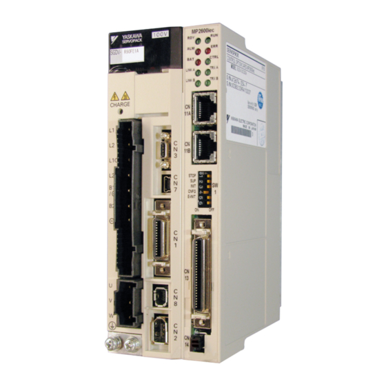
Page 6: Mp2600Iec Appearance
1.2 MP2600iec Appearance 1.2 MP2600iec Appearance The following figure shows the external appearance of the MP2600iec controller (Note: The servo amplifier is not shown). LED (10 points) Ethernet Port A Ethernet Port B DIP Switch (6 points) CN13 Port Analog I/O, Digital I/O External Encoder (incremental) 3.6V Lithium Battery... - Page 7 1.3.1 Sigma-5 Model Number Designation SGDV R70 A E 1 A 000 00 0 300 Series SGDV SERVOPACK Option Module Code Specifications Current MP2600iec 1.5 Axis Applicable Servomotor Machine Controller Voltage Code Max. Capacity kW Module 0.05 Options (parameter) 100V...
- Page 8 1.3 Model Number Reference 1.3.2 Sigma-7 Model Number Designation 1.3.2 Sigma-7 Model Number Designation To order SERVOPACKs with the MP2600iec option, use the following model numbers. SGD7S 11th+12th+ 1st+2nd+3rd 5th+6th 8th+9th+10th Σ-7 Series digit digit 13th digits digits digits digits...
-
Page 9: Model Number Reference
Type Model Part Number Note Battery JZSP-BA01 Replacement Battery Holder Kit SGDV-OZC02A Replacement (does not include battery) CN13 (MP2600iec) Terminal Block CBK-U-MP2Bxx Conversion Kit xx denotes cable length (m) CN13 (MP2600iec) A5 = 0.5 CFC-U-MP2Bxx (Flying Leads) 01 = 1... - Page 10 1.3 Model Number Reference 1.3.3 Accessory Model Numbers...
-
Page 11: Specifications
2.1 General Specifications 2 Specifications 2.1 General Specifications Item Specifications Ambient Operating 0 to 55°C Temperature Ambient Storage -20°C to +85°C Temperature Ambient Operating 90% RH or less (with no condensation) Humidity Ambient Storage 90% RH or less (with no condensation) Environmental Humidity Conditions... -
Page 12: Mp2600Iec Hardware Specifications
2.2 MP2600iec Hardware Specifications 2.2 MP2600iec Hardware Specifications Item Specification 200 MHz, 32 bit, ARM 9 SDRAM 32 MB Memory SRAM 512 kB with battery backup Flash 4 MB flash. Code and parameter storage. 10 LEDs (red and green - operating mode,... -
Page 13: Mechanical Installation
3.1 Mounting Information 3 Mechanical Installation 3.1 Mounting Information The MP2600iec controller is pre-assembled to the Sigma-5 or Sigma- 7 servo amplifier by the factory. -
Page 14: Installation Standards
3.2 Installation Standards 3.2 Installation Standards The servo amplifier must be installed in a fully enclosed metal control panel. Observe the standards for mounting servo amplifiers in control panels, including those for the mounting servo amplifiers side by side in one control panel as shown in the following illustration. •... -
Page 15: Dimensions
3.3 Dimensions 3.3.1 MP2600iec Controller 3.3 Dimensions 3.3.1 MP2600iec Controller (20) Dimensions in mm. - Page 16 3.3 Dimensions 3.3.1 MP2600iec Controller This page left intentionally blank...
-
Page 17: Inputs/Outputs
4.1 CN13 Connection Diagram 4 Inputs/Outputs 4.1 CN13 Connection Diagram CN13 External Device Analog -15V Output AO_GND -10 +10V External Device -15V Analog AI_GND Input -10 +10V Pulse Encoder Generator Interface PILC(24V) PILC(12V) Connect a positive voltage to pin 10, 34, or 9 based on signal level PILC(5V) Z-phase Latch Input... -
Page 18: Cn13 Connection Description
4.2 CN13 Connection Description 4.2 CN13 Connection Description Alphabetical Numerical CN 13 Pin Code Description Description Code CN 13 Pin Analog Output Analog Input Analog Input Analog Input Ground AI_GND no connection Analog Output Encoder A phase + Analog Output Ground AO_GND Encoder A phase - Digital Input 0... -
Page 19: External Encoder Interface
4.3 External Encoder Interface 4.3 External Encoder Interface Item Specification Number of One channel (Phase A, Phase B, Index pulse) channels Phase A & B: 5V differential input (RS-422 compatible), non-insulated. Maximum frequency 4MHz. Input circuit Index pulse: 5V/12V/24V photo coupler input. Maximum frequency 500kHz (pre-quadrature. -
Page 20: Controller Digital I
4.4 Controller Digital I/O 4.4.1 Inputs 4.4 Controller Digital I/O 4.4.1 Inputs • 8 general purpose • Optically isolated • 24 V @ 5 mA • Entire bank is configurable as either current sinking or sourcing via connection of common Digital Input Circuit To configure all controller inputs as sinking, wire +24VDC to pins 13 and 38. - Page 21 4.4 Controller Digital I/O 4.4.2 Outputs 4.4.2 Outputs • 8 general purpose • Optically isolated • 24 V @ 50 mA • Current source or sink (connection to both emitter and collector are provided) • High speed digital output feature can set DO_07 within 13s of passing a specified encoder position.
-
Page 22: Sigma-5 / Sigma-7 I
4.4.2 Outputs 4.5 Sigma-5 / Sigma-7 I/O Sigma-5 and Sigma-7 SERVOPACKS include seven digital inputs and three digital outputs that can be monitored and controlled by the MP2600iec. Photocoupler output Max. operating voltage: 30 VDC Max. operating current: 50 mA DC SERVOPACK 3.3kΩ... -
Page 23: Analog I
4.6 Analog I/O 4.6.1 Analog Input 4.6 Analog I/O 4.6.1 Analog Input Item Specification Analog input range -10V ~ +10V Number of input channels Electrical isolation None Absolute maximum input ± 15V Input Impedance 20k Resolution 16 bit 25°C ±0.1% (± 10mV) Accuracy 0 ~ 55°C ±0.3% (±... - Page 24 4.6 Analog I/O 4.6.2 Analog Output 4.6.2 Analog Output Item Specification Analog output range -10V ~ +10V Number of output channels Electrical isolation None Maximum load current ± 5mA Resolution 16 bit 25°C ±0.45% (± 45mV) Accuracy 0 ~ 55°C ±0.60% (±...
-
Page 25: Dip Switches
5.1 Switch Settings 5 DIP Switches 5.1 Switch Settings STOP CNFG EINIT DHCP Setting for Switch Name Setting Operating Mode Normal Details Operation User program execution inhibited STOP Inhibits user program execution Normal operation Firmware programming Enables controller firmware programming. mode (See Section 11) Normal operation... - Page 26 5.1 Switch Settings This page left intentionally blank...
-
Page 27: Led Outputs
6 LED Outputs 6 LED Outputs The following table shows the indicators that show the operating status of the controller and error information. Indicator Color Status Green Lit during normal operation. Green Lit during execution of user program. Lit when alarm occurs. Lit when malfunction occurs. - Page 28 6 LED Outputs This page left intentionally blank...
-
Page 29: Battery
1. Power off the MP2600iec. 2. Set the “INIT” switch (S11) to ON. 3. Power on the MP2600iec and wait for the “RDY” LED to illuminate. 4. Power off the MP2600iec. 5. Set the “INIT” switch (S11) to OFF. - Page 30 7.3 Battery Holder Installation Instructions: 7.3 Battery Holder Installation Instructions: Remove the plastic case from the controller by pressing the tabs at the top and bottom. Insert the tab of the metal plate into the last vent slot on the bottom front of the case as shown.
-
Page 31: Ethernet
8.1 Connectivity Information 8 Ethernet 8.1 Connectivity Information The MP2600iec supports 100MB speeds exclusively. Two separate networks are possible using both CN11A and CN11B. A default gateway can be specified only for the network attached to CN11A. 8.2 Ethernet Connector Details Ethernet Connector Specification and Pin Array The following table provides the Ethernet connector specifications. -
Page 32: Ethernet Cable
Up to 100m 100Base-TX 100Base-TX Ethernet Switch Ethernet Switch Up to 100m Up to 100m Up to 100m * Note: The MP2600iec can only be plugged into Station* Station* a 100Base-TX Ethernet port. Specification When Connecting to a Item Ethernet Switch... - Page 33 Connection Example 2 Sigma-5 or Sigma-7 with MP2600iec 100 Base-TX (up to 100m) Note: The MP2600iec can only be plugged into a 100Base-TX Ethernet port. Caution High frequency wave noise from other devices in the installation environment may cause errors in communications. When designing a system, use protective measures to avoid the influence of high frequency wave noise as follows: 1.
- Page 34 8.4 Ethernet Connection Examples Connection Example 3 Sigma-5 or Sigma-7 with MP2600iec Station* * Note: The MP2600iec can only be plugged into a 100Base-TX Ethernet port Core 100Base-TX Core 100Base-TX Ethernet Switch Servomotor MotionWorks IEC...
-
Page 35: Cable Diagrams
9.1 CBK-U-MP2B-xx (Controller Terminal Block) 9 Cable Diagrams 9.1 CBK-U-MP2B-xx (Controller Terminal Block) CBK-U-MP2B-XX Function Chart for MP2600iec Signal Signal Function Function Name Name Analog output AO_GND Analog output ground Analog input AI_GND Analog input ground reserved Phase A pulse (+) -
Page 36: Cfc-U-Mp2B-Xx (Controller Flying Lead)
9.2 CFC-U-MP2B-xx (Controller Flying Lead) 9.2 CFC-U-MP2B-xx (Controller Flying Lead) Dimensions in mm Model X =Cable Length CFC-U-MP2B-A5 500 mm CFC-U-MP2B-01 1000 mm CFC-U-MP2B-03 3000 mm Color Signal Color Signal Function Function (Solid/Band) Name (Solid/Band) Name Analog output BLK/RED Analog output RED/BLK AO_GND ground... -
Page 37: Sbk-U-Vba-Xx (Servo Amp Terminal Block)
9.3 SBK-U-VBA-xx (Servo Amp Terminal Block) 9.3 SBK-U-VBA-xx (Servo Amp Terminal Block) SBK-U-VBA-xx Function Chart for Sigma-5 or Sigma-7 Servo Amplifier Mechatrolink-II type Servo Amplifier / Option type Pin No. Signal Function /BK+ (/SO1+) Brake interlock output (+) (General purpose output 1 (+)) /BK- (/SO1-) Brake interlock output (-) (General purpose output 1 (-)) ALM+... -
Page 38: Jzsp-Csi02-X-E (Servo Amp Flying Lead)
9.4 JZSP-CSI02-x-E (Servo Amp Flying Lead) 9.4 JZSP-CSI02-x-E (Servo Amp Flying Lead) SERVOPACK End Connector 10126 - 6000 EL ( by Sumitomo 3 M Ltd. ) Shell 10326 - 52 A 0 - 008 Cable ( Ivory ) SSRFPVV-SB AWG# 28 13 P ×... -
Page 39: Firmware Upgrade Procedure
10 Firmware Upgrade 10 Firmware Upgrade It is possible to upgrade the Controller firmware in the field. For detailed instructions, please refer to Product Note PN.MCD.08.083: Upgrading the MP2 iec Controller Firmware. This document may be downloaded from our website, www.yaskawa.com. - Page 40 10 Firmware Upgrade This page left intentionally blank...
-
Page 41: Emc Installation Conditions
SERVOPACK models such as the rack-mounted types as well. This section describes the EMC installation conditions satisfied in test conditions prepared by Yaskawa. The actual EMC level may differ depending on the actual system’s configuration, wiring, and other conditions. However, because this product is built-in, check that the following conditions are still met after being installed in the user’s... - Page 42 11 EMC Installation Conditions Single-phase 100 V Models R70, R90, 2R1, 2R8 + SGDV-OCC02A Shield box Brake Power Supply One turn SERVOPACK Brake U, V, W Power supply: Noise L1, L2 Single-phase 100 VAC filter Servomotor One turn Surge L1C, L2C absorber Two turn Encoder...
- Page 43 11 EMC Installation Conditions Three-phase 200 V Models R70, R90, 1R6, 2R8, 3R8, 5R5, 7R6) + SGDV-OCC02A Shield box Brake Power Supply SERVOPACK Brake U, V, W Power supply: Noise L1, L2, L3 Three-phase 200 VAC filter Servomotor One turn Surge L1C, L2C absorber...
- Page 44 11 EMC Installation Conditions Three-phase 200 V Model 120 + SGDV-OCC02A Shield box Brake Power Supply SERVOPACK Brake U, V, W Noise Power supply: L1, L2, L3 filter Three-phase 200 VAC Servomotor One turn Surge L1C, L2C absorber Encoder One turn General I/O Controller Core...
- Page 45 11 EMC Installation Conditions Three-phase 200 V Models 180, 200, 330 + SGDV-OCC02A Shield box Brake Power Supply SERVOPACK Brake U, V, W Noise Power supply: L1, L2, L3 filter Three-phase 200 VAC Servomotor One turn Surge L1C, L2C absorber Encoder One turn General I/O...
- Page 46 11 EMC Installation Conditions Three-phase 200 V Models 470, 550, 590, 780 + SGDV-OCC02A Shield box Brake Power Cooling fan Supply SERVOPACK Brake U, V, W Noise Power supply: L1, L2, L3 filter Three-phase 200 VAC Servomotor Surge L1C, L2C absorber Encoder Regenerative...
- Page 47 11 EMC Installation Conditions Three-phase 400 V Models 1R9, 3R5, 5R4, 8R4, 120, 170 + SGDV-OCC02A Shield box Power supply: Brake Power Noise Single-phase Supply filter* 200 VAC Surge SERVOPACK absorber Control Brake power U, V, W 24 V, 0 V supply 24 VDC* Servomotor...
- Page 48 11 EMC Installation Conditions Three-phase 400 V Models 210, 260, 280, 370 + SGDV-OCC02A Shield box Power supply: Brake Power Noise Single-phase Supply filter* 200 VAC Surge SERVOPACK absorber Control Brake power U, V, W 24 V, 0 V supply 24 VDC* Servomotor Power supply:...
- Page 49 11 EMC Installation Conditions Attachment Methods of Ferrite Cores One turn Two turn Cable Cable Ferrite core Ferrite core Recommended Ferrite Core Cable Name Ferrite Core Model Manufacturer Motor main circuit cable ESD-SR-250 NEC TOKIN Corp. Recommended Noise Filter and Surge Absorber For more information on recommended noise filters and surge absorbers, refer to Sigma-5 Product Catalog.
- Page 50 11 EMC Installation Conditions...
- Page 52 Phone: 81-3-5402-4511 Fax: 81-3-5402-4580 http://www.yaskawa.co.jp YASKAWA AMERICA, INC. 2121 Norman Drive South, Waukegan, IL 60085, U.S.A. Phone: (800) YASKAWA (800-927-5292) or 1-847-887-7000 Fax: 1-847-887-7310 http://www.yaskawa.com YASKAWA ELÉTRICO DO BRASIL, LTDA. Avenida Piraporinha 777, Diadema, São Paulo, 09950-000, Brasil Phone: 55-11-3585-1100 Fax: 55-11-3585-1187 http://www.yaskawa.com.br...
Need help?
Do you have a question about the MP2600iec and is the answer not in the manual?
Questions and answers