Table of Contents
Advertisement
Advertisement
Chapters
Table of Contents
Troubleshooting

Related Manuals for Schlage PIB300


Summary of Contents for Schlage PIB300
- Page 1 *P516-097* P516-097 PIB300 and PIB301 User Guide Installation and operation instructions for Panel Interface Board Para el idioma español, navegue hacia www.schlage.com/support Pour la portion française, veuillez consulter le site www.schlage.com/support...
-
Page 2: Table Of Contents
Handheld device (HHD) ....................4 PIB300/PIB301 installation ....................4 Location.........................4 Wiring to the lock......................4 Connect the PIB300/PIB301 to the access control panel (ACP) ........4 Cable/wire specifications ....................5 Typical wiring to the access control panel ..............5 PIB300/PIB301 to ACP connection ..................6 Complete the installation ....................8 Access point ACP connections to a RS-485 device address ........8... -
Page 3: Overview
Provides two-way communication with locks via a RS-485 connection • The PIB300 may connect up to two Schlage AD-300 locks or up to two RS-485 based legacy locks communicating with the RSI or VIP protocol, may connect to an Access Control Panel (ACP) or reader interface board •... -
Page 4: Handheld Device (Hhd)
Wiring of locks requires one connector via the RS-485 connector (J5). • Connections from lock to lock should be daisy-chained (see diagram below). • The power supply is located at or near the PIB300/PIB301 for short wire runs, or local to locks if located far from the panel. RS485 PIB300... -
Page 5: Cable/Wire Specifications
Notes: Only AP1 is shown connected. AP2 should be connected the same way. Unsupervised, ground switched inputs to panel shown. Some Access Control Panels require supervised inputs and/or “dry contact” isolated inputs. The optional Schlage RLBD is available for these applications. -
Page 6: Pib300/Pib301 To Acp Connection
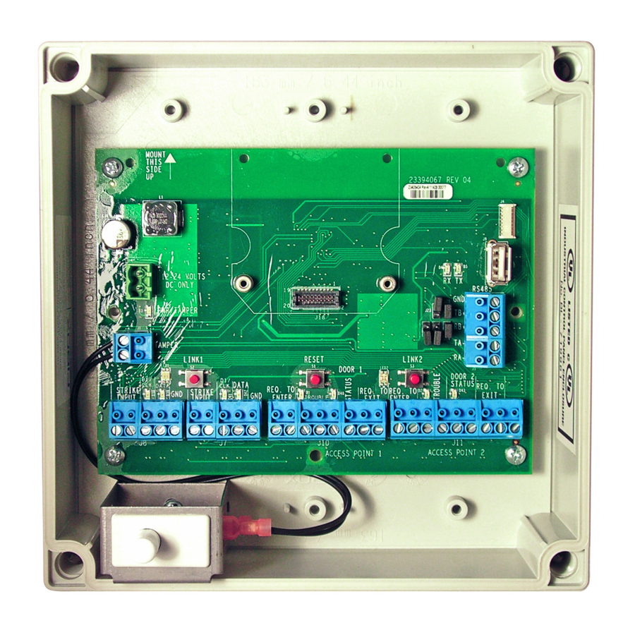
DOOR 1/2 needs to know the access point portal Door status STATUS J10/J11 state. input common Logic polarity is configurable. contact (GND) Output is pulled-up to 3.6 VDC and can sink 50mA. 6 • Schlage • PIB300 / PIB301 user guide... - Page 7 Connect only if the access point needs J8 for to be unlocked (door) or raised (gate). Access J8/J7 Clock or PIB300/PIB301 outputs used to present Point A D1/CLK data 1 output card data to the ACP. J7 for For an access point with a magnetic...
-
Page 8: Complete The Installation
1. Remove the main cover. 2. Press and hold both link buttons for over 3 seconds. 3. Release both link buttons. The PIB300/PIB301 will blink the red lights beside each link button while configuration reset takes place. 4. The two green lights beside the link buttons will blink 3 times when the reset is complete. - Page 9 Release Date White Paper P. Bockelman M. Roberts 48533 03-28-14 Notes Title 1. printed two sides User Guide, AD-Series PIB300 2. printed black Creation Date Number Revision 3. tolerance: ± .13 12-21-2009 4. see sheet 2 for artwork P516-097 5. printed in country may vary Created By 6.
- Page 10 *P516-129* P516-129 AD-200 AD-201 Offline lock user guide Instructions for AD-Series offline locks Para el idioma español, navegue hacia www.allegion.com/us. Pour la portion française, veuillez consulter le site www.allegion.com/us.
- Page 11 UL Listed product, in accordance with the requirements of the Standards UL 294 and ULC S319. This product has been evaluated for CAN/ULC-S319 Class 1. 2 • Schlage • AD-200 user guide...
-
Page 12: Overview
Overview The Schlage AD-200/AD-201 is an off-line electronic lock in the AD-Series product line. The Schlage AD-201 is a FIPS-201-1 certified off-line electronic lock. • May be powered by batteries or connected to external power using a UL294 or ULCS318/ULCS319 listed power supply capable of sourcing at least 250 mA @ 12 or 24 VDC. -
Page 13: Lock Functions
Save this user guide for future reference. Schlage Utility Software (SUS) The Schlage Utility Software is used for programming and setup only. The SUS is used to configure locks. This includes transferring data files between the access control software and locks. For information about the SUS, refer to the SUS user guide. -
Page 14: Construction Access Mode
In the factory default state, locks with keypads have a default PIN of 13579 and “#”, which can be used for installation, testing and construction access. To test, enter default PIN. The Schlage button will blink and the lock will unlock. -
Page 15: Cancel Construction Access Mode
CARD + Card ID Number credential – a card (with a unique Card ID number) presented to the lock. (See a description of Card ID number above for more information.) Steps for designating each form are in the Manual programming instructions on the following pages. 6 • Schlage • AD-200 user guide... -
Page 16: Manual Programming Instructions
Manual programming instructions Important notes: Wait for the Schlage button LEDs to stop flashing before continuing to the next step. Programming mode will time out if no entry is made in 20-25 seconds. Time out is indicated by three left and nine right red blinks of the Schlage button. -
Page 17: Normal Use Credentials
CARD + Number lock. back to step 4 Card ID Number OR press Present Wait for again to finish Programming right green Wait for card light. confirmation: 2 right green blinks. 8 • Schlage • AD-200 user guide... -
Page 18: Toggle Credentials
CARD + Number lock. back to step 4 Card ID Number OR press Present again to finish Wait for Programming Wait for right green card confirmation: light. 2 right green blinks. 9 • Schlage • AD-200 user guide... -
Page 19: Freeze Credentials
CARD + Number lock. back to step 4 Card ID Number OR press Present again to finish Wait for Programming Wait for right green card confirmation: light. 2 right green blinks. 10 • Schlage • AD-200 user guide... -
Page 20: Pass Through Credentials
Through Number lock. back to step 4 CARD + Card ID OR press Present Number again to finish Wait for Programming Wait for right green card confirmation: light. 2 right green blinks. 11 • Schlage • AD-200 user guide... -
Page 21: Other Programming
10 second delay blinks. card Error codes All error codes are indicated on the Schlage button by a solid red left LED, and a blinking green right LED. The number of green blinks indicates the error code. Number of Error code description... -
Page 22: Test Lock Operation
3. For locks with a card reader, present a credential to the reader. The lock will beep and the left side of the Schlage button will blink red one time. When the lock is in factory default mode, no credentials are accepted. -
Page 23: Wired Remote Release Feature
Operation with firmware version 2.45.1 • When the remote release button is pressed the lock will unlock for the programmed relock delay period. The Schlage LEDs will flash green once to indicate the lock is unlocked. The beeper will not sound. •... -
Page 24: Reset To Factory Defaults
5. The Schlage button and IPB will both light green for one second and a one-second beep will be heard. This indicates that the lock has been reset. -
Page 25: Batteries
For installations requiring ULC-S319, these battery models should be used. AA batteries: Duracell PC1500, MN1500; Energizer E91, EN91, AX91, XR91; RayoVac 815, 815-HE Coin cell batteries: Energizer CR2025, CR2032; Maxell CR2025, CR2032, Panasonic CR2025, CR2032; RayoVac KECR2025, KECR2032. 16 • Schlage • AD-200 user guide... -
Page 26: Low Battery Indications
CAN/UL-S318 or CAN/ULC-S319 for cUL installations. The power supply must be capable of sourcing at least 250 mA @ 12 or 24 VDC (Schlage PS902, PS904, PS906). When powered with external power supply, the lock will always fail Polarity Required “As-Is”... -
Page 27: Led Reference
With door closed, press IPB to release 4 red blinks privacy 1 If DPS is used, then opening the door will also release privacy. If mortise deadbolt is used, then retracting the deadbolt will also release privacy. 18 • Schlage • AD-200 user guide... -
Page 28: Troubleshooting
Check that the switch closes and completely installed. delivers less than 5 ohms resistance The remote release switch when activated. may not be functioning correctly. 19 • Schlage • AD-200 user guide... -
Page 29: Fcc/Ic Statements
FCC/IC Statements Allegion Agency statements Compliance Statement This device complies with Part 15 of the FCC Rules. Operation is subject to the following two conditions: This device may not cause harmful interference, and This device must accept any interference received, including interference that may cause undesired operation. Warning Changes or modifications not expressly approved by the party responsible for compliance could void the user’s authority to operate the equipment. - Page 30 HK-II Terminal User’s Guide...
- Page 31 Schlage Biometrics, Inc. reserves the right to change, without notice, product offerings or specifications. No part of this publication may be reproduced in any form without the express written permission from Schlage Biometrics, Inc.
- Page 32 Table of Contents Introduction HandKey II Biometrics Principle of Operation The HandKey II Specifications Options UL Compliance Planning an Installation Site Preparation HandReader Placement Wiring Power Input Battery Backup Earth Ground and Shielding Earth Ground All Units Carry a Ground Line to Each Unit Door Control Output Lock Output Mode Card Reader Emulation Mode...
- Page 33 Wiring Connections Wiring Connections Wiring Examples Erasing the Memory Erasing HandReader Memory Enter a Command Menu If No One is Enrolled in the HandReader If Users are Enrolled in the HandReader Navigating Command Menus Programming the HandReader Authority Level Programming Order System Management and Maintenance Design an ID Numbering System Service Menu...
- Page 34 HandKey II Manual Data From Network Data To Network Enrollment Menu Preparation User Education Proper Hand Placement Left Hand Enrollment Read Score Navigating the Enrollment Menu Enrollment Commands Add User Remove User Security Menu Navigating the Security Menu Security Commands Set User Data Set TZ Table Reject Threshold...
- Page 35 Appendix D: Troubleshooting Guide Erasing the HandReader Setup and User Database Appendix D: Troubleshooting Guide Display Messages During Verification Beeper and LED Status During Verification Glossary Limited Warranty...
- Page 36 Introduction HandKey II The HandKey II is Schlage Biometrics’ fourth generation biometric access control HandReader . The HandReader records and stores the three-dimensional shape of the human hand for comparison and identity verification. Upon verification, the HandReader produces an output that can unlock a door, send card format data to an access control panel, or communicate with a host computer.
- Page 37 Introduction HAND PLACEMENT DISPLAY VERIFICATION LIGHTS LCD DISPLAY NUMERICAL KEYPAD FUNCTION KEYS PLATEN AND GUIDE PINS Figure 3-1: The HandKey II The HandReader has an integrated keypad for ID entry and reader programming. It has two function keys (F1 and F2) that can be set to activate external devices such as a doorbell or an automatic door.
- Page 38 HandKey II Manual Specifications Size: 8.85 inches wide by 11.65 inches high by 8.55 inches deep (22.3 22.3 cm wide by 29.6 cm high by 21.7 cm deep Power: 12 to 24 VDC or 12 to 24 VAC 50-60 Hz, 7 watts Weight: 6 lbs (2.7 kg) Wiring:...
- Page 39 Introduction Options HandKey units have the following options available. See Technical Note 70200-0012 rev C • Backup Battery Support See Technical Note 70200-0013 rev C • Modem Communication See Technical Note 70200-0014 rev H • Ethernet Communication Hand Readers are UL Listed as stand alone units only (i.e. the card reader function UL Compliance has not been evaluated by UL).
- Page 40 For the following sections, Schlage Biometrics does not supply hardware items such as door control relays, door locks, switches, relays, communications or power wiring, or power supplies (a PS-110 or PS-220 power supply can be purchased from Schlage Biometrics to power the HandReader).
- Page 41 A full-wave bridge rectifier input structure is used in the power supply of the HandReader, making the polarity of terminals 1 and 2 irrelevant. Schlage Biometrics recommends using terminal 1 for positive (+) voltage and terminal 2 for common (-) for consistency. If J12 is used to attach power with the optional Schlage Biometrics wall-mount power supply, terminal 1 will reflect +13.8 VDC (unregulated) and terminal 2 will be power supply...
- Page 42 HGU network installation. Always adhere to any applicable electrical codes for your area. Schlage Biometrics is not responsible for damage done to units due to improper wiring.
- Page 43 Planning an Installation CARD SWITCH READER OUTPUTS INPUTS INPUT 1 2 3 4 5 6 7 8 9 10 12 13 14 EARTH GROUND CONNECTION PINS Figure 4-2: Earth Ground Connection Terminals There are two standard methods for providing earth grounding to HandKey units: •...
- Page 44 HandKey II Manual For systems with multiple units on a network, there will be a series of cables daisy- chained between the units, and the shield of each leg of the network should be connected to ground at only one end. It does not matter which end. An example of this method of grounding is shown in Figure 2-3.
- Page 45 Planning an Installation However, the power supplies must be truly floating, with no hidden paths back to the high-voltage side of the transformers, or to earth ground. Since this is difficult to achieve (there is always some parasitic capacitance between the primary and secondary in any transformer), this method may be more susceptible to high-frequency transients in the high-voltage side of the power lines than the earth-grounded method.
- Page 46 HandKey II Manual An open collector transistor driver drives each one of these outputs. Open collector refers to a transistor configuration capable of sinking current (by “pulling down” one side of a load to ground) but not able to source current – e.g. the transistor output is incapable of supplying current to drive up the output voltage and must rely on an external voltage source to accomplish this.
- Page 47 Planning an Installation...
- Page 48 • Up to 32 HandReaders can be linked together on a 2-wire RS-485 or 4-wire RS-422 Remote network. HandReader in • Two twisted-pair, shielded, AWG 22 (or larger) wire should be used (Schlage a HandReader Biometrics recommends Belden 82732 or its equivalent). Network •...
- Page 49 Typically, HandReader networks link to a PC using an RS-422 connection. These networks have the following requirements. • Two twisted pair, shielded, AWG 22 wire or larger should be used (Schlage Biometrics recommends Belden No. 82723 or equivalent cable). • HandReaders must be wired together in a “daisy chain” network from HandReader to HandReader and then to the host PC.
- Page 50 Mechanical Installation Select an installation location based on the guidelines provided in the Planning an Installation section beginning on page 7. Wall Plate Installation NOTE For the following instructions protect the HandReader from the dust and debris generated during the wall plate installation process. 1.
- Page 51 Mechanical Installation 5. For a solid wall, hold the wall plate against the wall, centering the leveling hole over the mark in the wall. 6. Align a bubble level with the top edge of the wall plate and gently rotate the wall plate until the bubble level shows that the top edge of the wall plate is level.
- Page 52 HandKey II Manual Attaching the 1. Remove the HandReader from its carton. 2. Align the sleeves of the back plate with the pins of the wall plate and slide the HandReader HandReader to the left as shown in figure 4-2. HOLE 2 UPPER SCREWS SURFACE...
- Page 53 Mechanical Installation Closing the With the wall mount latch in the unlocked position, swing the body of the HandReader up and rotate the key away from the wall. Hold the top of the HandReader firmly against the HandReader wall and rotate key towards wall, locking the latch into place (see Figure 4-3). NOTE Do not force the HandReader onto the wall mount latch when the latch is in the locked (down) position.
- Page 54 Wiring Connections Once the HandReader is attached to the wall plate the wiring connections to the HandReader can be made (see Figure 5-1). J7 Battery Reset WALL Wall Plate Jumper Switch Top of Power Terminal Optional Modem Serial RS-232 Terminal Connectors Strips or Ethernet...
- Page 55 Wiring Connections Table 7-1: TS-1 - Power and Communication Connections Terminal Connection RS-422 Rx- or RS-485 Rx-/Tx- RS-422 Tx- or RS-485 Rx+/Tx+ RS-422 Rx+ RS-422 Tx+ Table 7-2: TS-2 - Input Connections Terminal Connection Request to Exit Input Ground Door Monitor Switch Input (NC Standby) Auxiliary Input 1 Ground Auxiliary Input 2...
- Page 56 14 13 12 11 10 9 RS-422 Connection TOP OF THE HAND READER * These components are not supplied by Schlage Biometrics, Inc. ** The operation of the Auxiliary Inputs depend upon how the inputs have been configured. Figure 7-2: Lock Output Wiring Diagram...
- Page 57 18 17 16 15 RS-422 Connection TOP OF THE HAND READER * These components are not supplied by Schlage Biometrics, Inc. ** The operation of the Auxiliary Inputs depend upon how the inputs have been configured. Figure 7-3: Auxiliary Output Wiring Diagram...
- Page 58 HandKey II Manual Card Reader GROUND DATA 1 DATA 0 +5 VDC POWER Access Panel (SEE NOTE BELOW) GROUND DATA 1 DATA 0 WALL TO WHICH THE HAND READER IS ATTACHED HINGE 12 to 24 V AC/DC Input 18 17 16 15 14 13 12 11 10 9 8 7 6 5 4 3 2 1 RS-422...
- Page 59 Wiring Connections TS-1 Rx - 4-Wire Rx + RS-422 Tx - Connection Tx + Master TS-1 Rx - 4-Wire Rx + RS-422 Tx - Connection Tx + Remote 1 TS-1 Rx - 4-Wire Rx + RS-422 Tx - Connection Tx + Remote X Figure 7-5: RS-422 4-Wire Master/Remote Network System Wiring Diagram...
- Page 60 HandKey II Manual TS-1 Rx/Tx - 2-Wire Rx/Tx + RS-485 Connection Master TS-1 Rx/Tx - 2-Wire Rx/Tx + RS-485 Connection Remote 1 TS-1 Rx/Tx - 2-Wire Rx/Tx + RS-485 Connection Remote X Figure 7-6: RS-485 2-Wire Master/Remote Network System Wiring Diagram...
- Page 61 Wiring Connections DC-102 Power Supply RS-232 to 4-wire RS-422 Data Converter (P/N DC-102) DB-25 Serial Port TS-1 Rx - Rx + RS-422 Connection Tx - Tx + Remote TS-1 Rx - Rx + RS-422 Connection Tx - Tx + Remote TS-1 Rx - Rx +...
- Page 62 Figure 7-8: Printer to HandKey II Wiring Diagram All HandReaders in a network must be set to the same communication method. Four-wire RS-422 cabling is required for HandNet for Windows™ network installations. Schlage Biometrics does not recommend two-wire RS-485 cabling for new network installations.
- Page 63 Wiring Connections...
- Page 64 Erasing the Memory There are two options when erasing the memory of the HandReader. 1. Setup 2. All The erasing of the setup will set the HandReader’s address, passwords, etc. back to factory defaults. Choosing the All option will take the HandReader’s setup back to factory defaults plus erase all user databases and datalogs.
- Page 65 Erasing the Memory...
- Page 66 Enter a Command Menu Press the keys simultaneously to enter a command menu. Clear Enter If No One is 1. The display appears as follows. Enrolled in the HandReader ENTER PASSWORD 2. Press the default password for the menu you wish to enter. Press for the Service Menu.
- Page 67 Enter a Command Menu If Users are 1. The display appears as follows. Enrolled in the HandReader ENTER PASSWORD 2. Enter your ID number on the keypad and place your hand on the platen for verification. 3. If verification is successful, the display appears as follows. 4.
- Page 68 The default menu passwords are given in Table 6. To increase the security of the HandReader, Schlage Biometrics recommends changing the passwords for the command menus to new numbers. These password numbers can...
- Page 69 Authority Level to 5. This protects the integrity of the system by enacting the Authority Level rules described in the list above. Schlage Biometrics strongly recommends assigning at least two users to Authority Level 5 to ensure that more than one person has the authority to access all menus and all commands.
- Page 70 HandKey II Manual System Once a HandReader network is in operation the following commands are used to manage and maintain the HandReader network. Management 1. Set Reader Operating Thresholds – Set the Reject and Number-of-Tries HandReader operating thresholds to meet the site’s security requirements. This is done through Maintenance the Security Menu.
- Page 71 Programming the HandReader...
- Page 72 Service Menu The Service Menu commands provide information that helps you determine if the HandReader is operating properly and within normal operating parameters. Navigating the Once you have entered the Service menu, there are three options available for navigating the command menu system. Service Menu •...
- Page 73 Service Menu Calibrate The Calibrate command verify that the HandReader’s exposure values are within normal operating parameters. The normal operating parameters are shown in Table 2. Table 11-7: Normal Operating Parameters Parameter Normal Range Row “r” 0 +/- 2 Column “c” 0 +/- 2 Exposure 100 +/- 20...
- Page 74 Setup Menu The Setup menu commands allow you to set the basic operating parameters for the HandReader. NOTE Once in the Setup menu you can step through and set the parameters for each command sequentially. You do not have to exit command mode after setting any individual command.
- Page 75 Setup Menu Table 12-8: Setup Command Menu Setup Menu Password = 2 Set Language Select Language Set Date Format Select Date Format Set Time and Date Month (MM) Day (DD) Year (YY) Hour (HH) Minute (MM) Set Address New Address Set ID Length New ID Length Set Facility...
- Page 76 HandKey II Manual Set Language The Set Language command allows the language shown on the HandReader’s display to be “localized” for a variety of countries. The default language is English. The following languages are available. English Japanese French Polish German Portuguese Indonesian Russian...
- Page 77 Setup Menu Set the ID Length to the number of digits in the longest ID number. This command is unnecessary (and should be left at its default value) if ID entry is made from a card reader. The ID Length should not be set if a Duress Code is being assigned (see page 49).
- Page 78 HandKey II Manual In HandReader networks, one HandReader must be set as a Master HandReader and all remaining HandReaders must be set as Remote HandReaders. The default Reader Mode is Remote mode. Reader Mode does not apply to stand-alone HandReaders or HandReaders in a PC network (the HandReader should be left in its default value).
- Page 80 Management Menu The Management menu commands allow you to manage employee data stored in a HandReader. Navigating the Once you have entered the Management menu, there are three options available for navigating the command menu system. Management Menu • Press to enter the command shown on the display.
- Page 81 Management Menu Data From The Data from Network command allows the master HandReader to receive information from a HandReader on the network. This is used to transmit user enrollment and system Network configuration information from an existing HandReader to the master HandReader. Data To The Data to Network command transmits all data held by the master HandReader to all HandReaders connected to the network.
- Page 82 Duress code digit. • If you are enrolling large groups of people you may consider using an enrollment trainer. It is a replica of a platen that is available through your Schlage Biometrics dealer. 1. Refer to the Set User Data > Set Authority Level command in the Security command menu on page 55.
- Page 83 Enrollment Menu User Education The HandReader is easy to use and non-threatening. However, most people have never used a biometric HandReader. Training users on how the HandReader works and how to use it will eliminate most fears and concerns before they occur. Inform the users of these facts.
- Page 84 HandKey II Manual Read Score When a user uses the HandReader a number appears in the display. ID VERIFIED The number on the display reflects how accurately the user is placing his/her hand on the platen. Scores that vary greatly between low and high numbers are indicative of inconsistent hand placement.
- Page 86 Security Menu The commands in the Security menu control the security of the information within the HandReader and the sensitivity of the HandReader when reading hands. Navigating the Once you have entered the Security menu, there are three options available for navigating the command menu system.
- Page 87 Security Menu Table 15-12: Security Command Menu Security Menu Password = 5 Set User Data Set User Authority Level (Y/N) ID # Authority Level Set User Reject Level ID # Reject at # Set User Time Zone ID # New Time Zone? Edit Time Zone Time Zone # Time Zone Data...
- Page 88 HandKey II Manual Set User Data The Set User Data command allows you to set the User Authority level, the User Reject Level, and the User Time Zone. • The Authority Level controls which command menus a user is allowed to access; the higher the authority level, the greater the number of menus the user may access.
- Page 89 Security Menu Reject Use the Reject Threshold command to set the HandReader’s reject sensitivity level applied when reading hand data and to set the number of tries a user is allowed before Threshold being rejected by a HandReader. The reject sensitivity level and number of tries are global values. This means that these values are applied to all users on all HandReaders on the network –...
- Page 90 HandReader Maintenance A minimum amount of system maintenance is required to keep HandReaders fully functional. HandReaders should be cleaned periodically to prevent an accumulation of dust from affecting the HandReader’s readability. User Scores should be reviewed periodically to ensure the HandReader is performing properly. NOTE There are NO user serviceable parts inside the HandReader.
- Page 91 HandReader Maintenance...
- Page 92 Appendix A: Tips for a Successful Installation Unless the following tips are followed, the installation runs the risk of having some level of difficulties. These tips come from years of experience with thousands of sites installed around the world. By far the biggest problem tends to be that the HandReader is allowed to get dirty.
- Page 93 Appendix A: Tips for a Successful Installation Enrollment Bad enrollments equal bad verification (meaning scores will be too high). The key to successful verification is education. • Educate the Enrollee on Hand Geometry • Explain enrollment process • Train Enrollee on hand placement •...
- Page 94 Appendix B: Noted Board Configuration Differences Because of Schlage Biometrics’ camera retrofit of the HandReader some changes have been made to the main PCB and they are listed as follows: • Dipswitches have been removed • comm lines are terminated •...
- Page 95 Appendix B: Noted Board Configuration Differences Terminal Block Labeling OLD PCB NEW PCB Number Number 12-24 VDC (+) OR VAC (+) 5 VDC OUTPUT 12-24 VDC (-) OR VAC DATA/D0 CLOCK/D1 GROUND LOCK OR CLOCK OUTPUT BELL OR DATA OUTPUT AUXOUT 1 REX SWITCH AUXOUT 2...
- Page 96 HandKey II Manual Terminal Block Layout New Board Old Board J6 - 2 pin Power connector TS1 - 4 pin Comm connector TS2 - 6 pin Input connector TS3 - 8 pin Output connector Any of the grounds coming off of pins 8, 10, 12, 14, 18, 20, 22, 24, and 26 of the "Old Board"...
- Page 97 Appendix B: Noted Board Configuration Differences Memory Reset 1. To reset the memory of the HandReader follow these steps- 2. Remove power and battery jumper, if a back up battery is installed 3. Press down on reset button and apply power 4.
- Page 98 Appendix C: Old Board Configuration Information Wall Plate Installation Attaching the 1. Loosen the three bottom mounting screws until there is approximately 1/8 inch (3 mm) clearance between the screw head and the wall plate. HandReader 2. Remove the HandReader from its carton. 3.
- Page 99 Appendix C: Old Board Configuration Information Wiring Connections Once the Hand Reader is attached to the wall plate the wiring connections to the Hand Reader can be made (see Figure 17-2). Wall Plate WALL Top of Terminal RS-232 RJ-45 Backup Battery TS-1 Terminals 6 to 1 Jumper O F F...
- Page 100 HandKey II Manual CARD READER SWITCH INPUTS OUTPUTS INPUT 9 10 11 12 13 14 15 16 17 18 19 20 21 22 23 24 25 26 EARTH GROUND CONNECTION PINS Figure 19-8: Earth Ground Connection Terminals There are two standard methods for providing earth grounding to HandPunch units: •...
- Page 101 Appendix C: Old Board Configuration Information Table 19-13: TS-1 - Power and Communication Connections Terminal Connection Power Input 12 to 24 VDC/VAC Power Return RS-422 Rx- or RS-485 Rx-/Tx- RS-422 Tx- or RS-485 Rx+/Tx+ RS-422 Rx+ RS-422 Tx+ Table 19-14: TS-2 - Input Connections Terminal Connection Request to Exit Input Ground...
- Page 102 26 25 24 23 22 21 20 19 18 17 16 15 14 13 12 11 10 4-Wire RS-422 Connection TOP OF THE HAND READER * These components are not supplied by Schlage Biometrics, Inc. ** The operation of the Auxiliary Inputs depend upon how the inputs have been configured. Figure 19-9: Lock Output Wiring Diagram...
- Page 103 26 25 24 23 22 21 20 19 18 17 16 15 14 13 12 11 10 4-Wire RS-422 Connection TOP OF THE HAND READER * These components are not supplied by Schlage Biometrics, Inc. ** The operation of the Auxiliary Inputs depends upon how the inputs have been configured. Figure 19-10: Auxiliary Output Wiring Diagram...
- Page 104 TOP OF THE HAND READER * These components are not supplied by Schlage Biometrics, Inc. ** The operation of the Auxiliary Inputs depends upon how the inputs have been configured. NOTE: For +12 VDC readers, connect power supply +12 VDC to card reader.
- Page 105 Appendix C: Old Board Configuration Information TS-1 12 to 24 V AC/DC Input Rx - 4-Wire Rx + RS-422 Tx - Connection Tx + Master TS-1 12 to 24 V AC/DC Input Rx - 4-Wire Rx + RS-422 Tx - Connection Tx + Remote 1...
- Page 106 HandKey II Manual TS-1 12 to 24 V AC/DC Input Rx/Tx - 2-Wire Rx/Tx + RS-485 Connection Master TS-1 12 to 24 V AC/DC Input Rx/Tx - 2-Wire Rx/Tx + RS-485 Connection Remote 1 TS-1 12 to 24 V AC/DC Input Rx/Tx - 2-Wire...
- Page 107 Appendix C: Old Board Configuration Information DC-102 Power Supply RS-232 to 4-wire RS-422 Data Converter (P/N DC-102) DB-25 Serial Port TS-1 12 to 24 V AC/DC Input Rx - Rx + RS-422 Connection Tx - Tx + Remote TS-1 12 to 24 V AC/DC Input Rx -...
- Page 108 26 25 24 23 22 21 20 19 18 17 16 15 14 13 12 11 10 RS-422 RJ-45 Jack Connection TOP OF THE HAND READER * These components are not supplied by Schlage Biometrics, Inc. Figure 19-15: Printer to HandKey II Wiring Diagram...
- Page 109 Appendix C: Old Board Configuration Information Setting the DIP Switches DIP Switch settings perform three tasks for the Hand Reader (see Figure 17-11). Set End of Line (EOL) Termination to match the type of termination the network being used needs. •...
- Page 110 All Hand Readers in a network must be set to the same communication method. Four- wire RS-422 cabling is required for HandNet for Windows™ network installations. Schlage Biometrics does not recommend two-wire RS-485 cabling for new network installations. Erasing HandReader Memory The erase memory function allows a Hand Reader’s setup and/or user database to be...
- Page 111 Appendix C: Old Board Configuration Information Closing the HandReader Before closing the Hand Reader, ensure dip switches 4 and 5 are OFF (refer to Figure 17-11). With the wall mount latch in the unlocked position, swing the body of the Hand Reader up and lock the latch into place with the key provided with the Hand Reader (see Figure 17-12).
- Page 112 Appendix D: Troubleshooting Guide Display Various messages can appear on the HandPunch’s display during hand verification. These messages are defined in. Messages During Table 20-17: Display Messages During Verification Verification Message Definition PLACE HAND The platen is ready to receive your hand for verification. ID VERIFIED You are verified, proceed.
- Page 113 Appendix D: Troubleshooting Guide Beeper and The HandPunch’s beeper and LED status display also display hand verification information. This information is defined in. LED Status During Table 20-18: Beeper and LED Status During Verification Verification Operation Beeps Meaning During Keypad Entry 1 per Keystroke –...
- Page 114 Glossary Address, IP – An Internet Protocol address is a unique address assigned to a computer for communicating over the Internet. It is made up of 4 sets of numbers, separated by periods (for example, 123.245.78.901). Address, Reader – A Hand Reader Address is a unique identification number assigned to a Hand Reader.
- Page 115 Glossary Transaction – A Transaction is any kind of event recorded at a Hand Reader. Transactions may include actions such as accepted or denied hand reads, input and output events, and doors opening and closing. Wiegand™ Reader – The term “Wiegand Reader” has two meanings depending upon its application.
- Page 116 DAMAGES OF ANY NATURE ARISING FROM THE SAME OR THE USE OF THE PRODUCT. Schlage Biometrics Inc. reserves the right to make changes in the design of any of its products without incurring any obligation to make the same change on units previously...
- Page 117 As a $2 billion provider of security solutions for homes and businesses, Allegion employs more than 7,800 people and sells products in more than 120 countries across the world. Allegion comprises 23 global brands, including strategic brands CISA , Interflex , LCN , Schlage and Von Duprin ® ® ® ®...
- Page 118 PG1000 USB Proximity Desktop Reader and Programmer User Guide...
- Page 119 Contents Contents Requirements and Specifications ......................... 3 Items needed (Included in the box): ........................3 Computer Requirements ............................ 3 Minimum ............................... 3 Recommended ............................. 3 Technical Specifications ............................. 3 Installation Procedure ............................4 Installing the Software: ............................4 Installing the Hardware: ............................4 Operation .................................
-
Page 120: Requirements And Specifications
Requirements and Specifications Requirements and Specifications Items needed (Included in the box): 1. XceedID Desktop Proximity Programmer and Credential Reader 2. Host A to Device mini-B USB Cable 3. Compact Disc containing the software user interface and this user manual 4. -
Page 121: Installation Procedure
Installation Procedure Installation Procedure The order of installation does not matter, though installing the Software first is recommended. Installing the Software: 1. Place the installation CD in the CD-ROM drive. 2. The disk should auto-play. If the disc does not auto-play: a. -
Page 122: Operation
Operation Operation Default After the Desktop Reader/Programmer has been plugged into the host computer, it will function as a desktop reader. In this mode the device behaves much like a keyboard. If a user presents a credential before setting the decoding options, the device will print the binary information of the card into the active window or data field if it receives text. -
Page 123: Programmer Mode
Operation Programmer Mode To get the device into Programmer Mode, the user must click the programmer tab at the top of the application window. This will change the window to allow the user to program a card or multiple cards. The user must then specify all of the following options then click the program button. -
Page 124: Troubleshooting
Troubleshooting Troubleshooting Problem Solution Solution Device is not recognized by my Unplug device from PC and plug it Unplug device from USB port and plug computer back in into a different USB port Device not programming cards Verify that the device is in programmer Verify cards are XceedID Proximity mode the LED indicator should be credentials (Device will not program... - Page 125 ©2010 XceedID Corporation. All rights reserved. 23735707 Rev. 10/10-a...
- Page 126 E XXXXXXXXXXXX XXXXXXXXXXXX O 1st bit transmitted O = Odd parity bit computed over all underlined data bits E = Even Parity bit computed over all highlighted data bits X = data bit ©2010, Schlage Lock Company 23759103 Rev. 11/10-a...
- Page 127 *P516-098* P516-098 WPR400 Wireless Portable Reader User guide Para el idioma español, navegue hacia www.allegion.com/us Pour la portion française, veuillez consulter le site www.allegion.com/us...
- Page 128 Test mode ........................10 Set link mode on the PIM400 ..................11 Use the WPR400 in test mode ..................12 WPR400 test mode LED reference ................12 Improve RF communication ..................12 Batteries ..........................13 Troubleshooting ......................14 FCC/IC statements ......................14 2 • Schlage • WPR400 user guide...
-
Page 129: Overview
Follow these steps when setting up a WPR400. 1. If the PIM400 is not yet installed, install the PIM400. Refer to the user guide that came with the PIM400 or visit www.allegion.com/us (see Support>Schlage Electronics> Electronic Locks Technical Library) for more information. -
Page 130: Wpr400 Operation
Connecting a reader to the WPR400 (if necessary) 1. Connect the reader cable to the reader as shown below. Reader Reader cable 2. Secure the reader to the front cover using the screws and washers provided. 4 • Schlage • WPR400 user guide... -
Page 131: Permanently Or Temporarily Mount The Wpr400
(“loop” side) to the mounting surface, positioned ® according to the placement of strips on the WPR400’s base. 3. Press the WPR400 to the mounting surface with both sets of strips aligned. 5 • Schlage • WPR400 user guide... -
Page 132: Schlage Utility Software (Sus)
LEDs to stop blinking. 6. Press the credential reader Schlage button two (2) times quickly. The WPR400 is communicating with the SUS when the Schlage button blinks alternate right/left red and the SUS display indicates “WPR400” at the bottom of the main screen. -
Page 133: Link To A Pim400 (Reader Mode Only)
The number of green blinks/beeps indicates the RF channel number. 6. If the link fails, the WPR400 Schlage button will blink red three (3) times and five (5) short beeps will sound. The PIM400 will remain in link mode, so the link may be attempted again. -
Page 134: Change The Rf Channel
PIM400. The WPR400 radio frequency (RF) channel is controlled by the PIM400 it is linked with. The RF channel in use may be changed on the PIM400 through the Schlage Utility Software (SUS). Follow these steps to change the RF channel on the WPR400. -
Page 135: Reset To Factory Defaults
Level 1 factory default reset will delete all lock settings as found in the “edit” tab on the “lock properties” screen on the SUS. Edit tab 1. Remove the WPR400 cover. 2. Press and hold Schlage button until Inside Push Button two (2) beeps sound (10 seconds). 3. Release the Schlage button. -
Page 136: Test Mode
When powered on, the WPR400 will automatically enter test mode and test the quality of the RF link. If the RF link fails, the Schlage button will blink red three (3) times and five (5) short beeps will sound. Repeat the link attempt by either of the following methods (the PIM400 will remain... -
Page 137: Set Link Mode On The Pim400
6. The corresponding LED (LED1 for LINK1, LED2 for LINK2) blinks red and green. This indicates that the PIM400-TD2 is in Link Mode. To abort link mode, press the same switch again. J2, DC Power Link 2 Button Link 1 Button PIM400-TD2 printed circuit board (PCB) 11 • Schlage • WPR400 user guide... -
Page 138: Use The Wpr400 In Test Mode
PIM400-TD2 or PIM400-485 outside the closet, then mount it in the closet with the Schlage omnidirectional (remote) Antenna mounted outside the closet. 3. If the link problem still exists, use a PIM400-TD2 with a Schlage directional (remote) antenna aimed at the non-linking WPR400 test location. -
Page 139: Batteries
3. Remove the battery retainer and battery holder. 4. Remove the old AA batteries from the battery holder. 8. Reattach the WPR400 cover making sure no wires are pinched. 13 • Schlage • WPR400 user guide... -
Page 140: Troubleshooting
Note: The intended use of this module is not for the general public. It is generally for industry/commercial use only. This transceiver is to be professionally installed in the end product by Allegion, and not by a third party. The Schlage XPB-COMAD400V2 900 MHz Communication Board Module will not be sold to third parties via retail, general public or mail order. - Page 141 To comply with IC RF exposure limits for general population/uncontrolled exposure, the antenna(s) used for this transmitter must be installed to provide a separation distance of at least 20 cm from all persons and must not be collocated or operating in conjunction with any other antenna or transmitter. 15 • Schlage • WPR400 user guide...
- Page 142 Customer Service © Allegion 2015 P516-098 Rev. 12/15-e 1-877-671-7011 www.allegion.com/us...
- Page 143 Wireless Access CONFIGURING & OPERATING INSTRUCTIONS SCHLAGE WIRELESS ACCESS SYSTEM (WAS) The most current version of this document is available for download at: http://www.ir-swa.com P/N: M053-007-D...
- Page 144 Wireless Access Schlage Ingersoll Rand Security Technologies 245 W. Roosevelt Road, Building 7, Suite 48 West Chicago, IL 60185 main: 800-313-2962 (630-876-5680) technical support: 866-322-1237 fax: 630-293-4257 web: ir-swa.com Copyright © 2003-2006 Ingersoll Rand, all rights reserved. No part of this document can be reproduced, transmitted, or transcribed in any form by electrical, mechanical, optical, manual, or otherwise without the prior written consent of Ingersoll Rand.
- Page 145 Wireless Access CONFIGURING & OPERATING INSTRUCTIONS NOTE: This manual is intended to be used after the Schlage Wireless Access Modules have been installed. Each Schlage Wireless Access module has its own installation manual. Use this manual to configure and operate your system.
- Page 146 Wireless Access Linking to the WPIM by Powering the WRI-IN..................32 Testing the WRI-IN .............................33 Re-linking a WRI-IN and WPIM.........................34 Changing the RF Channel..........................34 Updating the WRI-IN’s Firmware .......................34 Wireless Portable Readers, Version 2 (WPR2) ....................35 The WPR2 Audio/Visual Indicators ......................36 Turning the WPR2 On ..........................36 Linking or Re-Linking to the WPIM by Resetting the WPR2..............36 Testing the WPR2............................37...
- Page 147 Wireless Access 12.7 Updating the WPR’s Firmware........................55 Other Important Information........................56 13.1 Knowing When to Change the RF Channel.....................56 13.2 Configuring the Schlage Wireless Access System................56 13.3 Extended Unlock .............................56 13.4 Why Swipe a Card When the Power Is Disconnected? ................57 13.5 Presenting a HID iCLASS Proximity Card....................57...
-
Page 148: Schlage Wireless Access System (Was)
Regardless of which WPIM or WAPM module is used, the communication link between the WPIM and WAPM is always RF. This manual describes the configuration and operation of all the WPIMs and WAPMs in the Schlage Wireless Access Product Line. -
Page 149: Panel Interface Module (Pim)
2. Panel Interface Module (PIM) The Panel Interface Module (PIM) is a product in the Schlage Wireless Panel Interface Module (WPIM) category. The PIM is the wireless interface to an access control panel. Table 2-1 & Table 2-2 show the PIM sales models and their major specifications. -
Page 150: 2.1 How To Determine The Version Of Pim Pcb
Wireless Access MAXIMUM ACCESS CONTROL PANEL MODEL* ENCLOSURE NUMBER LOCATION INTERFACE/DESCRIPTION OF WAPMs Magnetic (clock & data) or PIM-TD2 plastic indoor Wiegand (data1/data0) Magnetic (clock & data) or PIM-TD4 plastic indoor Wiegand (data1/data0) RS485 PIM-485-OTD plastic indoor (OEM specific protocol) Magnetic (clock &... - Page 151 Wireless Access Figure 2-1 – PIM-TD2 & PIM-EXP Printed Circuit Board (PCB) Figure 2-2 – PIM-485-OTD Printed Circuit Board (PCB) Ingersoll Rand Security Technologies 245 W. Roosevelt Road, Bldg 7, Suite 48, West Chicago, IL 60185 / (800) 313-2962 / (630) 293-4257 fax P/N: M053-007-D www.ir-swa.com Page 9 of 60...
-
Page 152: 2.2 The Pim Indicators
Wireless Access 2.2 The PIM Indicators There are five LEDs on the PIM PCB: CR15 (green), CR7 and CR10 (red), CR6 and CR9 (green and red). These LEDs indicate the current status of the PIM-TD2/PIM-TD3/PIM-EXP (Table 2-3) or PIM-485-OTD (Table 2-4) and the WAPMs linked to it. PIM-TD2/PIM-TD4/PIM-EXP LED Indication Condition CR 15... -
Page 153: 2.3 How To Set An Rf Channel
2.3.1.1 United States Non Dynamic Channel Switching (default) In the United States version of Schlage Wireless Access products, one of fifteen RF channels can be set using DIP switch SW7 on the PIM (Figure 2-1 or Figure 2-2). Table 2-5 shows how to set the PIM’s SW7 to select the desired RF channel:... - Page 154 Wireless Access 2.3.1.2 United States Dynamic Channel Switching When using the United States version of Schlage Wireless Access products in the dynamic channel switching mode, one of five RF channel groups can be set using DIP switch SW7 on the PIM (Figure 2-1 or Figure 2-2).
- Page 155 2.3.2 Australian Version 2.3.2.1 Australian Non Dynamic Channel Switching (default) When using the Australian version of Schlage Wireless Access products in the non dynamic channel switching mode, one of seven RF channels can be set using DIP switch SW7 on the PIM (Figure 2-1 or Figure 2-2).
-
Page 156: 2.4 Putting The Pim-Td2, Pim-Td4 And Pim-Exp Into Link Mode
Wireless Access 2.4 Putting the PIM-TD2, PIM-TD4 and PIM-EXP into Link Mode Note: To put a PIM-485-OTD into Link Mode the Configuration & Demonstration Tool (CDT) must be used. Refer to the appropriate PIM addendum manual for specific instructions. The Link Mode allows 2 WAPMs to be linked to a PIM-TD2 or PIM-EXP. The Link Mode allows 4 WAPM’s to be linked to a PIM-TD4. -
Page 157: 2.8 Updating The Pim's Firmware
Wireless Access 2.8 Updating the PIM’s Firmware The PIM Programming Connector, J2 (Figure 2-1 or Figure 2-2) is used to install a new version of the PIM firmware into the PIM. If a new firmware version is required, please refer to the “Upgrading a WAPM or WPIM’s Firmware”... -
Page 158: Panel Interface Module Expander (Pim-Exp)
Module (WPIM) category. The PIM-EXP installs in a PIM-TD2 enclosure and provides the ability to interface 1 or 2 additional Schlage Wireless Access Point Modules (WAPM) to an Access Control Panel. Figure 3-1 shows the PIM-TD2 enclosure with PIM-EXP installed. -
Page 159: Wa Series Integrated Lockset (Wa5200 Or Wa5600)
Wireless Access 4. WA Series Integrated Lockset (WA5200 or WA5600) The WA Series Integrated Lockset is a product in the Schlage Wireless Access Point Module (WAPM) category. Cylindrical (WA5200) and mortise (WA5600) lockset versions are available. AUWA5200 and AUWA5600 are Australian versions of the WA series integrated locksets. -
Page 160: 4.1 The Wa5200/Wa5600 Audio/Visual Indicators
Wireless Access 4.1 The WA5200/WA5600 Audio/Visual Indicators MIRL Action LED Indications Sounder WA is powered and then displays X red flashes then Y green flashes none software version number WA Relocks (motor runs) 1 red flash 1 beep If linking, WA sends a link request 1 green flash;... -
Page 161: 4.2 Linking A Wa5200/Wa5600 To A Wpim
Wireless Access 4.2 Linking a WA5200/WA5600 to a WPIM NOTE: Only one WAPM can be linked at a time. 4.2.1 If the WA does not have a Battery Pack installed, install one now (section 4.4). 4.2.2 Make certain that the WPIM to be linked to is in the Link Mode (Section 2.3.2). 4.2.3 To initiate the linking process: 4.2.3.1 Open the door. -
Page 162: 4.3 Testing A Wa5200/Wa5600
Wireless Access Figure 4-7 – WA Battery Pack (K380-001) 4.3 Testing a WA5200/WA5600 4.3.1 Proximity Card Reader Models 4.3.1.1 Place the card flat to and within 1 to 3 inches of the upper part of the Proximity Reader (Figure 4-8). The reader sounder beeps. NOTE: For HID iCLASS reader versions of the WA see section 13.5, page 57, below. -
Page 163: Installing/Replacing A Wa5200/Wa5600 Battery Pack (K380-001)
Wireless Access 4.3.2.3 Turn the Lever and open the door. 4.3.2.4 Shortly after the green flash, there is a red flash and sounder beep signifying relock. 4.3.3 Indication of an Unsuccessful Card Read The best indication of an unsuccessful valid card read is when the WA’s internal sounder does not beep, indicating that the card was not read. -
Page 164: Updating The Mirl's Firmware
Wireless Access out of Link Mode and put back into Link Mode for the new RF channel to be selected. The WPIM is taken out of Link Mode by pressing the switch associated with the Access Point that is in the Link Mode (S1 or S2). -
Page 165: Wa Exit Trim (Wa993)
Wireless Access 5. WA Exit Trim (WA993) The WA Exit Trim (WA993) is a product in the Schlage Wireless Access Point Module (WAPM) category. AUWA993 is an Australian version of the WA exit trim. Note: In this section, WA993 refers to either a WA993 or an AUWA993. -
Page 166: 5.2 Linking The Wa993 To A Wpim
Wireless Access 5.2 Linking the WA993 to a WPIM NOTE: Only one WA993 can be linked at a time. 5.2.1 If the WA993 does not have a Battery Pack installed, install one now (section 5.4). 5.2.2 Make certain that the WPIM to be linked to is in the Link Mode (Section 2.3.2). 5.2.3 To initiate the linking process: 5.2.3.1 Open the door. -
Page 167: 5.3 Testing The Wa993
Wireless Access Figure 5-5 – WA993 Battery Pack (K380-001) 5.3 Testing the WA993 5.3.1 Proximity Card Reader Models 5.3.1.1 Place the card flat to and within 1 to 3 inches of the Proximity Reader (Figure 5-6). Figure 5-6 - Presenting a Proximity Card to a WA993 5.3.1.2 The green LED flashes and the lock will unlock. -
Page 168: Installing/Replacing The Wa993 Battery Pack (K380-001)
Wireless Access 5.3.3 Indication of an Unsuccessful Card Read The best indication of an unsuccessful valid card read is when the WA993’s internal sounder does not beep, indicating that the card was not read. If an invalid card is read, the WA993’s red LED flashes twice and the internal sounder beeps once. In both cases the WA993 remains locked. -
Page 169: Outdoor Wireless Reader Interface (Wri-Otd)
Wireless Access 6. Outdoor Wireless Reader Interface (WRI-OTD) The Outdoor Wireless Reader Interface (WRI-OTD-12VDC) is a product in the Schlage Wireless Access Point Module (WAPM) category. AUWRI-OTD-12VDC is an Australian version of the outdoor wireless reader interface. Note: In this section, WRI-OTD refers to either a WRI-OTD-12VDC or an AUWRI-OTD-12VDC. -
Page 170: 6.1 The Wri-Otd Visual Indicators
Wireless Access 6.1 The WRI-OTD Visual Indicators There are two LEDs on the WRI-OTD PCB: a red Power LED (LED1, Figure 6-3) and a green/red State LED (LED2, Figure 6-3). These LEDs indicate the current status of the WRI-OTD (Table 6-1). LED Indication Condition LED1... -
Page 171: 6.3 Testing The Wri-Otd
Do this test if a Request to Exit device is wired to the WRI-OTD Portal Inputs (J7-3 & 4, Figure 6-3). Using either the Schlage Configuration and Demonstration Tool (CDT) or the Access Control Panel software (ACP Software), verify that activating the Request to Exit device causes a request to exit to be sent to the CDT or ACP software. -
Page 172: 6.4 Re-Linking A Wri-Otd And Wpim
Do this test if an electrical lock or load is connected to the WRI-OTD Auxiliary Portal Output (J8-4, 5, and/or 6, Figure 6-3). Using either the Schlage Configuration and Demonstration Tool (CDT) or the Access Control Panel software (ACP Software), verify that Auxiliary Portal Output can control the electrical lock or load. -
Page 173: Indoor Wireless Reader Interface (Wri-In)
Wireless Access 7. Indoor Wireless Reader Interface (WRI-IN) The Wireless Reader Interface (WRI-IN) is a product in the Schlage Wireless Access Point Module (WAPM) category. AUWRI-IN-12VDC is an Australian version of the indoor wireless reader interface. Note: In this section, WRI-IN refers to either a WRI-IN-12VDC or an AUWRI-IN-12VDC. -
Page 174: 7.1 The Wri-In Visual Indicators
Wireless Access 7.1 The WRI-IN Visual Indicators Depending on how the Card Reader is interfaced to the WRI-IN, the LED on the Card Reader may display some WRI-IN status conditions (Table 7-1). Condition Card Reader LED WRI-IN is powered and then displays Y green flashes software version number WRI-IN sends a link request (up to 3 times... -
Page 175: 7.3 Testing The Wri-In
Do this test if a Request to Exit device is wired to the WRI-IN Portal Inputs (Figure 7-3). Using either the Schlage Configuration and Demonstration Tool (CDT) or the Access Control Panel software (ACP Software), verify that the activating the Request to Exit device causes a request to exit to be sent to the CDT or ACP software. -
Page 176: 7.4 Re-Linking A Wri-In And Wpim
Do this test if an electrical lock or load is connected to the Strike Portal Output (Figure 7-3). Using either the Schlage Configuration and Demonstration Tool (CDT) or the Access Control Panel software (ACP Software), verify that Strike Portal Output can control the electrical lock or load. -
Page 177: Wireless Portable Readers, Version 2 (Wpr2)
8. Wireless Portable Readers, Version 2 (WPR2) The Wireless Portable Reader, Version 2 (WPR2) is a product in the Schlage Wireless Access Point Module (WAPM) category (Figure 9-1 and Figure 9-2). AUWPR2 is an Australian version of the wireless portable reader. -
Page 178: 8.1 The Wpr2 Audio/Visual Indicators
Wireless Access 8.1 The WPR2 Audio/Visual Indicators WPR2 Action LED Indication Sounder WPR2 is powered and then displays X red flashes then Y green flashes none software version number If linking, WPR2 sends a link 1 green flash; request (up to 3 times per RF then 1 red flash none channel) looking for a WPIM in link... -
Page 179: 8.4 Testing The Wpr2
Wireless Access 8.3.4 During linking, the WPIMs LED (CR6 or CR9, depending on the WPR2 being linked) blinks green (some intermittent red may be seen) and the WPR2 LED (Figure 9-1 or Figure 9-2) blinks green (some intermittent red may be seen) for about 20 seconds while the WPR2 & WPIM determine the integrity of the selected RF channel. -
Page 180: 8.6 Changing The Rf Channel
Wireless Access Figure 9-4 – Battery Retainer Figure 9-5 – Disconnecting Battery Pack 8.5.3 Connect the new Battery Pack connector to the mating connector coming from the transceiver board (Figure 9-6). Figure 9-6 - Installing New Battery Pack 8.5.4 Carefully pack the battery wires, position the Battery Pack in its original location, and re-install the Battery Retainer (Figure 9-4). -
Page 181: Wireless Status Monitor (Wsm)
Wireless Access 9. Wireless Status Monitor (WSM) The Wireless Status Monitor (WSM) is a product in the Schlage Wireless Access Point Module (WAPM) category. AUWSM is an Australian version of the wireless status monitor. Note: In this section, WSM refers to either a WSM or an AUWSM. -
Page 182: 9.1 The Wsm Visual Indicators
Wireless Access 9.1 The WSM Visual Indicators NOTE: LED assembly must be installed on the GRN_LED & RED_LED connections of J3 in order for any visual indicators to be seen (see Fig. 10-3). Action LED Assembly on J3 WSM is powered and then displays X red flashes then Y green flashes software version number WSM is ready to start linking... -
Page 183: Replacing The Wsm Battery Pack, K380-001
Wireless Access 9.2.6 Re-install the WSM cover, making certain that no wires are pinched. The cover should go on easy with no interferences. Replace the 4 cover screws, one in each corner (Figure 10-1). 9.2.7 The WSM is now ready for normal operation. 9.3 Replacing the WSM Battery Pack, K380-001 Approximately one month prior the end of the WSM’s Battery Pack life, a Low Battery Trouble signal is indicated at the WPIM (Table 2-4), a Trouble signal will be sent to the access control panel. -
Page 184: 9.4 Re-Linking An Wsm And Wpim
Wireless Access 9.4 Re-linking an WSM and WPIM To re-link a WSM and WPIM follow the instructions in Section 9.1. 9.5 Changing the RF Channel At the WPIM, change DIP switch SW7 to the desired new RF channel (Section 2.3), place the PIM in Link Mode (see Section 2.3.2), then re-link the desired WSM (Section 9.4). -
Page 185: Modular Integrated Reader Lock (Mirl)
Wireless Access 10. Modular Integrated Reader Lock (MIRL) The Modular Integrated Reader Lock (MIRL) is a product in the Schlage Wireless Access Point Module (WAPM) category. Figure 10-1 – MIRL Locked Side (Outside) Figure 10-2 – MIRL Unlocked Side (Inside) 10.1 The MIRL Audio/Visual Indicators... -
Page 186: 10.2 Linking The Mirl To A Wpim
Wireless Access 10.2 Linking the MIRL to a WPIM NOTE: Only one WAPM can be linked at a time. 10.2.1 If the MIRL does not have a Battery Pack installed, install one now (section 4.4). 10.2.2 Make certain that the WPIM to be linked to is in the Link Mode (Section 2.3.2). 10.2.3 To initiate the linking process: 10.2.3.1 Open the door. -
Page 187: 10.3 Testing The Mirl
Wireless Access Figure 10-5 – MIRL Battery Pack (K380-001) 10.3 Testing the MIRL 10.3.1 Proximity Card Reader Models 10.3.1.1 Place the card flat to and within 1 to 3 inches of the upper part of the Proximity Reader (Figure 4-8). The reader sounder beeps. NOTE: For HID iCLASS reader versions of the MIRL see section 13.5, page 57, below. -
Page 188: Installing/Replacing The Mirl Battery Pack (K380-001)
Wireless Access 10.4 Installing/Replacing the MIRL Battery Pack (K380-001) Approximately one month prior the end of the MIRL Battery Pack life, a Low Battery Trouble signal is indicated at the WPIM (Table 2-4) and a Trouble signal will be sent to the access control panel. To install or replace the MIRL Battery Pack, remove the MIRL Transceiver Cover (Figure 4-5). -
Page 189: Wireless Exit Trim Kit (Wexk)
Wireless Access 11. Wireless Exit Trim Kit (WEXK) The Wireless Exit Trim Kit (WEXK) is a product in the Schlage Wireless Access Point Module (WAPM) category. Figure 11-1 – WEXK Locked Side (Outside) Figure 11-2 – WEXK Unlocked Side (Inside) Ingersoll Rand Security Technologies 245 W. -
Page 190: 11.1 The Wexk Audio/Visual Indicators
Wireless Access 11.1 The WEXK Audio/Visual Indicators WEXK Action LED Indications Sounder WEXK is powered and then displays X red flashes then Y green flashes none software version number WEXK Relocks (motor runs) 1 red flash 1 beep If linking, WEXK sends a link 1 green flash;... -
Page 191: 11.3 Testing The Wexk
Wireless Access 11.2.4 During linking, the WPIM’s LED (CR6 or CR9, depending on the door being linked) and the WEXK LED blink green (some intermittent red may be seen) for about 20 seconds while the WEXK & WPIM determine the integrity of the selected RF channel. 11.2.5 If the WEXK &... -
Page 192: Installing/Replacing The Wexk Battery Pack (K380-001)
Wireless Access Figure 11-6 - Presenting a Proximity Card 11.3.1.2 The green LED flashes and the lock will unlock. 11.3.1.3 Turn the Lever and open the door. 11.3.1.4 Shortly after the green flash, there is a red flash and sounder beep signifying relock. 11.3.2 Magnetic Stripe Reader Models 11.3.2.1 Place the card at the top of the Magnetic Stripe Reader. -
Page 193: 11.6 Re-Linking A Wexk And Wpim
Wireless Access NOTE: If the Card Reader Base Plate has a Tamper Switch that is activated when the Reader Cover is removed, then the Card Reader is disabled. Tamper Switch must be manually held closed (simulating the cover being installed) for the Card Reader to operate. Figure 11-7 –... -
Page 194: Wireless Portable Readers (Wpr)
Wireless Access 12. Wireless Portable Readers (WPR) The Wireless Portable Reader (WPR) is a product in the Schlage Wireless Access Point Module (WAPM) category (Figure 8-1). Figure 8-1 – Wireless Portable Reader (WPR) with Proximity Reader 12.1 The WPR Audio/Visual Indicators... -
Page 195: 12.2 Turning The Wpr On
Wireless Access 12.2 Turning the WPR On The WPR is turned On & Off using the On/Off switch located on the WPR cover (Figure 8-1). When the WPR is turned on, Action 1, Table 8-12-1 occurs. Actions 2a, 2b, 2c, and/or 2d will only occur if the WPR is being linked (Section 12.3). -
Page 196: Replacing The Wpr Battery Pack, K380-001
Wireless Access 12.4.2 Proximity Card Reader Models 12.4.2.1 Place a valid card flat to and within 1 to 3 inches of the upper part of the Proximity Reader. The reader sounder beeps. 12.4.2.2 The green LED will flash when a valid card is read. 12.4.3 Indication of an Unsuccessful Card Read The best indication of an unsuccessful valid card read is when the WPR’s internal sounder does not beep, indicating that the card was not read correctly. -
Page 197: 12.7 Updating The Wpr's Firmware
Wireless Access 12.5.5 To continue to use the WPR on the same RF channel and with the same WPIM, re-install the cover, making certain that no wires are pinched. The cover should go on easy with no interferences. Replace the 4 cover screws, one in each corner (Figure 8-1). If the WPR needs to be re-linked or the RF channel needs to be changed, before re-installing the WPR cover, follow the instructions in Section 12.2 or Section 12.6. -
Page 198: 13. Other Important Information
13.3 Extended Unlock Extended unlock is a feature that permits a Schlage Wireless Access Point Module (WAPM) to stay in an indefinite unlock state. Normally a card is swiped at a WAPM and if it is a valid card, the Access Point will unlock for a short period of time (seconds) and then automatically relock. -
Page 199: 13.4 Why Swipe A Card When The Power Is Disconnected
Wireless Access Note: The exact time that the Access Point will be unlocked or locked depends on the frequency of RF activity between the WAPM and the WPIM. Generally the WAPM is in a low power mode (i.e. sleeping) and therefore the WPIM can only communicate with the WAPM when the WAPM initiates the communication. -
Page 200: 14. Contacting Technical Support
Wireless Access 14. Contacting Technical Support For questions regarding Schlage Wireless Access: www.ir-swa.com main: 800-313-2962 (630-876-5680) technical support: 866-322-1237 fax: 630-293-4257 Ingersoll Rand Security Technologies 245 W. Roosevelt Road, Bldg 7, Suite 48, West Chicago, IL 60185 / (800) 313-2962 / (630) 293-4257 fax P/N: M053-007-D www.ir-swa.com... -
Page 201: 15. Fcc Compliance, Aca Compliance, & Warnings
• The Schlage Wireless Access System Component must be installed by qualified professionals or contractors in accordance with FCC part 15.203, Antenna Requirements. • Do not use any antenna other than the one provided with the unit. -
Page 202: 16. Revision History
Wireless Access 16. Revision History Version Date Changes X1.0 11/12/01 preliminary in house release for comments 11/15/01 changed protected/unprotected to locked/unlocked, released for publication (IRL) 11/20/01 added WPR section, grammar edits, added power off card swipe explanation, added FCC & warning section 11/27/01 released for publication (IRL, WPR) X03.0... - Page 203 HP-3000/4000 Terminal User’s Guide...
- Page 204 Schlage Biometrics, Inc. reserves the right to change, without notice, product offerings or specifications. No part of this publication may be reproduced in any form without the express written permission from Schlage Biometrics, Inc.
- Page 205 Table of Contents Introduction Biometrics Principle of Operation Specifications Planning an Installation Site Preparation HandPunch Placement Wiring Power Input Battery Backup Earth Ground and Shielding Communications External Devices Mechanical Installation Wall Plate Installation Mounting the Wall Plate Networking and Communications Stand-alone HandReader Master or Remote HandReader in a HandReader Network Remote HandReader in a HandReader Network Connected to a Host PC...
- Page 206 Appendix B - Differences in Board Layout Appendix C - Old Installation Guide Appendix D - Troubleshooting Glossary Limited Warranty...
- Page 207 HandPunch 3000/4000 Manual Introduction The HandPunch 3000/4000 is part of Schlage Biometrics’ 3rd generation line of biometric hand geometry Time and Attendance Terminals . The HandPunch records and stores a three-dimensional shape of the human hand for comparison and identity verification. Upon verification, the HandPunch records the time, date, user ID number, and collected time and attendance data for collection by a host computer.
- Page 208 Electronic hand geometry technology first appeared in the 1970s. Schlage Biometrics Inc., founded in 1986, built the first mass-produced hand geometry readers and made biometric technology affordable for the commercial market. Today, Schlage Biometrics’ products are in use in every imaginable application from protecting cash vaults to verifying employee attendance in hospitals.
- Page 209 HandPunch 3000/4000 Manual Four different features assist the user with hand placement and read verification. 1. A light emitting diode (LED) hand placement display on the HandPunch’s top panel assists users with hand placement on the platen. 2. A liquid crystal display (LCD) shows operational data and programming menus.
- Page 210 Introduction HAND PLACEMENT DISPLAY VERIFICATION LIGHTS LCD DISPLAY NUMERICAL KEYPAD BAR CODE CARD READER FUNCTION KEYS PLATEN AND GUIDE PINS : The HandPunch 4000...
- Page 211 HandPunch 3000/4000 Manual Specifications Table 1: Specifications Size: 8.85 inches wide by 11.65 inches high by 8.55 inches deep. 223 cm wide by 29.6 cm high by 21.7 cm deep. Power: 12 to 24 VDC or 12 to 24 VAC 50-60 Hz, 7 watts Weight: 6 lbs (2.7 kg) –...
- Page 212 Introduction Table 1: Specifications Time Schedules: HP-4000 – 3 definable time schedules per user Auxiliary Inputs: 2 (open collector, 5 VDC present, sinks to ground, 100 mA max) Auxiliary Outputs: up to 3 user definable (open collector, 5 VDC present, sinks to ground, 100 mA max) Options HandPunch units have the following options available.
- Page 213 HandPunch 3000/4000 Manual...
- Page 214 Introduction This page is intentionally blank.
- Page 215 40 in. (102 cm.) Figure 2-1: HandPunch Placement Rules NOTE For the following sections, Schlage Biometrics does not supply hardware items such as door control relays, door locks, switches, relays, communications or power wiring.
-
Page 216: Battery Backup
External Devices • The minimum wire size for these circuits is AWG 22; the maximum wire size is AWG 18. Schlage Biometrics recommends using Belden 82732 or its equivalent when wiring for RS-422 communications. Power The HandPunch uses an internal switching regulator to obtain internal Input operational power. - Page 217 HandPunch and plugs into jack J4 on the keypad control circuit board located in the top of the chassis. Earth Schlage Biometrics recommends that all HandPunchs be grounded with a Ground solid, reliable earth ground connection. This connection establishes a common...
- Page 218 HGU network installation. Always adhere to any applicable electrical codes for your area. Schlage Biometrics is not responsible for damage done to units due to improper wiring.
- Page 219 HandPunch 3000/4000 Manual There are two standard methods for providing earth grounding to HandPunch units: earth grounding all units (see Figure 2-3) • carrying an earth ground to each unit (see Figure 2-4) • Earth ground all units when there is a good earth ground source near each unit and/or when there are very long cable runs between units.
- Page 220 Planning An Installation Master Remote 1 Remote 2 Connect the Connect the Cable Shield to Cable Shield to Remote 1's Remote 2's Ground Ground To Next Remote Connect the Cable Do Not Connect Do Not Connect Do Not Connect Shield to the the Cable Shield the Cable Shield the Cable Shield...
- Page 221 HandPunch 3000/4000 Manual elevator motors or other large-current drawing machines) will have no effect on the communication network if this configuration is used. However, the power supplies must be truly floating, with no hidden paths back to the high-voltage side of the transformers, or to earth ground. Since this is difficult to achieve (there is always some parasitic capacitance between the primary and secondary in any transformer), this method may be more susceptible to high-frequency transients in the high-voltage side of the power...
- Page 222 4-conductor cable in an RS-232 serial configuration. A 6’ or 50’ cable may be Connection purchased through Schlage Biometrics or a wiring diagram for the RS-232 to host computer connection is found on “Table 4” on page 33. If you make the RS-232 to host computer connection you cannot use the serial NOTE printer option (see page 21).
- Page 223 HandPunch 3000/4000 Manual When wiring the RS-422 daisy-chain network, do not wire HandPunch NOTE terminals in a “star” network (a network where a number of units are all connected to the network at one, central location – see Figure 2-5). Hand Hand Punch...
- Page 224 The external DC power supplies and relays needed to operate external NOTE devices such as bells or door locks are NOT provided by Schlage Biometrics. You must provide these power supplies. The bell control circuit switches direct current to ground when actuated. The...
- Page 225 You can connect a serial printer to a HandPunch. A serial printer connected Serial Printer to the HandPunch prints punches as they occur. Schlage Biometrics does not supply serial printers. The connection to a serial printer is made through J4, the 4 pin connector on the HandPunch.
- Page 226 Planning An Installation This page is intentionally blank.
- Page 227 HandPunch 3000/4000 Manual Mechanical Installation Select an installation location based on the guidelines provided in the Planning an Installation section beginning on page 11. Wall Plate Installation For the following instructions protect the HandPunch from the dust and debris NOTE generated during the wall plate installation process.
- Page 228 Networking and Communications Align a bubble level with the top edge of the wall plate and gently rotate the wall plate until the bubble level shows that the totp edge of the wall plate is level. Secure the plate to the wall using heavy masking tape. Using the wall plate as a template, mark the locations of teh two upper screw holes and the three lower screw holes.
- Page 229 HandPunch 3000/4000 Manual WIRE ENTRY POINT FOR RJ-11 JUNCTION BOX Wall Plate SURFACE CONDUIT ENTRY POINT 1.25" (3 cm) 50" Reference (127 cm) to Top of Wall Plate 2" WIRE ENTRY POINT (5 cm) 42.75" FOR SURFACE (108.6 cm) RJ-11 BOX 42.5"...
- Page 230 Networking and Communications HOLE 2 UPPER SCREWS SURFACE CONDUIT ENTRY KEYHOLE HOLES 3 LOWER MOUNTING SCREWS REAR OF TERMINAL : Attaching the HandPunch to the Wall Plate The Hand Punch is now ready for its wiring connections.
- Page 231 Multiple HandReaders can be linked to a presonal computer (PC) for an HandReader integrated access control network. Real time monitoring of door status and in a a variety of alarm types can be done with Schlage Biometrics’ HandNet for HandReader Windows™ (Schlage Biometrics model number HN-300) software. To run Network HandNet for Windows™, the computer must be PC compatible, using a...
- Page 232 Typically, HandReader networks link to a PC using an RS-422 connection. These networks have the following requirements: Two twisted pair, shielded, AWG 22 wire or larger should be used (Schlage • Biometrics recommends Belden No. 82723 or equivalent cable).
- Page 233 A serial printer can be connected to a HandReader. A printer connected to a Printer remote HandReader will print only the events that occur at that HandReader. Schlage Biometrics Inc. does not supply serial printers. Refer to the Printer String application note (available from Schlage Biometrics) for detailed information.
- Page 234 Networking and Communications This page is intentionally blank.
- Page 235 HandPunch 3000/4000 Manual Wiring Connections Once the HandPunch is attached to the wall plate the wiring connections to the HandPunch can be made (see Figure 4-1). J7 Battery Reset WALL Wall Plate Jumper Switch Terminal Power Top of Optional Modem Strips Connectors RJ-11...
- Page 236 Wiring Connections The following figures provide typical HandPunch wiring diagrams. “Figure 4-4” on page 34 provides a typical Bell Output wiring diagram. • “Figure 4-5” on page 35 provides a typical Lock Output wiring diagram. • “Figure 4-6” on page 36 provides a typical Input wiring diagram. •...
- Page 237 HandPunch 3000/4000 Manual Table 3: TS-2 - Output Connections Terminal Connection Auxiliary Output 2 Table 4: RS-232 Connection Signal Connection Ground Receive Data Input (from external device) Transmit Data Output (to external device) Ready to Send Output (to external device) Table 5: RJ-11/RS-422 Network Connection J3 Pin Signal...
- Page 238 Wiring Connections RS-232 Pins Figure 4-3: J4 - RS-232 Jack Pinout * POWER SUPPLY +12 to 24 VDC Max BELL *AUX RELAY WALL TO WHICH THE HANDREADER IS ATTACHED HINGE 12 to 24 V AC/DC Input 14 13 12 11 10 9 RJ-11 RS-422 Connection...
- Page 239 HandPunch 3000/4000 Manual * POWER SUPPLY +12 to 24 VDC Max *ELECTRIC LOCK *LOCK OR STRIKE RELAY WALL TO WHICH THE HANDREADER IS ATTACHED HINGE 12 to 24 V AC/DC Input 14 13 12 11 10 9 RJ-11 RS-422 Connection TOP OF THE HANDREADER * These components are not supplied by Recognition Systems, Inc.
- Page 240 Wiring Connections SWITCH LEGEND N.O. MOMENTARY* N.C. DOOR SWITCH* WALL TO WHICH THE HANDREADER IS ATTACHED HINGE 12 to 24 V AC/DC Input 14 13 12 11 10 9 RJ-11 RS-422 Connection TOP OF THE HANDREADER * These components are not supplied by Recognition Systems, Inc. ** The operation of the Auxiliary Inputs depend upon how the inputs have been configured.
- Page 241 HandPunch 3000/4000 Manual Card Reader GROUND DATA 1 DATA 0 +5 VDC POWER Access Panel (SEE NOTE BELOW) GROUND DATA 1 DATA 0 WALL TO WHICH THE HANDREADER IS ATTACHED HINGE 12 to 24 V AC/DC Input 14 13 12 11 10 9 RJ-11 RS-422 Connection...
- Page 242 Wiring Connections DC-102 RS-232 to 4-wire RS-422 Power Supply Data Converter (P/N DC-102) * RS-422 DB-25 4-Wire RJ-11 Jack Surface Serial (2 Twisted or Wall Plate Port Pairs) * RS-422 HandPunch 1 4-Wire (2 Twisted Pairs) HandPunch 2 * RS-422 4-Wire (2 Twisted Pairs)
- Page 243 HandPunch 3000/4000 Manual RSI Supplied Cable (Black) HandPunch RJ-11 Telephone Outlet Modem Port HandPunch RS-422 RJ-11 Port Modem Unit * RS-422 4-Wire RJ-11 Jack Surface (2 Twisted or Wall Plate Pairs) * RS-422 HandPunch 1 4-Wire (2 Twisted Pairs) HandPunch 2 * RS-422 4-Wire (2 Twisted...
- Page 244 Wiring Connections Ethernet Cable Connection to HandPunch Host Computer Ethernet Port via Ethernet HandPunch RS-422 Ethernet Unit RJ-11 Port * RS-422 4-Wire RJ-11 Jack Surface (2 Twisted or Wall Plate Pairs) * RS-422 HandPunch 1 4-Wire (2 Twisted Pairs) HandPunch 2 * RS-422 4-Wire (2 Twisted...
- Page 245 HandPunch 3000/4000 Manual *Host Computer/Hyperterminal *Serial Printer WALL TO WHICH THE HANDREADER IS ATTACHED HINGE HINGE 12 to 24 V 4 Pin AC/DC Connector Input 14 13 12 11 10 9 RJ-11 RS-232 Jack RS-422 Connection TOP OF THE HANDREADER * These components are not supplied by Recognition Systems, Inc.
- Page 246 Wiring Connections This page is intentionally blank.
- Page 247 HandPunch 3000/4000 Manual Erasing the Memory There are two options when erasing the memory of the HandReader: Setup The erasing of the setup will set the HandReader’s address, passwords, etc., back to factory defaults. Erasing Choosing the All option will take the HandReader’s setup back to factory HandReader defaults plus erase all user databases and datalogs.
- Page 248 Planning an Installation This page intentionally blank.
- Page 249 HandPunch 3000/4000 Manual Closing the HandPunch Before closing the HandPunch clear all dust and debris away from the HandPunch. With the wal mount latch in the unlocked position, swing the body of the HandPunch up and lock the latch into place with the key provided with the HandPunch (see Figure 6-1 below).
- Page 250 Planning an Installation This page intentionally blank.
- Page 251 HandPunch 3000/4000 Manual Enter Command Menu CLEAR ENTER Press the keys simultaneously to enter a command menu. If No One The display appears as follows: is Enrolled in the HandPunch ENTER PASSWORD Press the default password for the menu you wish to enter. Press 1 for the Service Menu.
- Page 252 Enter a Command Menu Enter Password Enter the password for the menu you wish to enter. The default passwords are as follows: Press 1 for the Service Menu. Press 2 for the Setup Menu. Press 3 for the Management Menu. Press 4 for the Enrollment Menu.
- Page 253 HandPunch 3000/4000 Manual Navigating Once you have entered a command menu, there are three options available for Command navigating the command menu system Menus Press to enter the command shown on the display. • Press to step to the next command in the menu. •...
- Page 254 Enter a Command Menu This page is intentionally blank.
- Page 255 A supervisor must enter the correct password for that menu to access that menu. The default menu passwords are given in Table 6. To increase the security of the HandPunch, Schlage Biometrics recommends changing the passwords for the command menus to new numbers. These password numbers can be up to 10 digits long.
- Page 256 The first person enrolled should be enrolled using the Add Supervisor command. This protects the integrity of the system. Schlage Biometrics strongly recommends enrolling at least two users as supervisors to ensure that more than one person has the authority to access all menus and all commands.
- Page 257 HandPunch 3000/4000 Manual System Management Onca a HandPunch system is in operation the following commands are used for system management. Supervisor Override – Review employee punch history, add bulk hours or dollars, or record a punch for an employee. This is done through the Management Menu.
- Page 258 Programming the HandPunch Service Menu The Service menu commands provide information that help you determine if the HandPunch is performing within normal operating parameters and identify the status of the unit’s inputs and outputs. The following section provides a brief summary of the Service Menu commands. There are no user serviceable parts inside the HandPunch.
- Page 259 HandPunch 3000/4000 Manual Calibrate The Calibrate command displays the HandPunch’s exposure values, allowing you to verify these values are within normal operating parameters. The standard operating parameters are shown in Table 8. Table 8: Normal Operating Parameters Parameter Normal Range Row “r”...
- Page 260 Programming the HandPunch Setup Menu The Setup menu commands allow you to set the basic operating parameters for the HandPunch unit. The following section provides a brief summary of all the parameters that may be set on a HandPunch unit. Once in the Command Menu, you can step through and set the parameters NOTE for each command sequentially.
- Page 261 HandPunch 3000/4000 Manual Table 9: Setup Command Menu Setup Menu Password = 2 Set Language Select Language Set Date Format Select Date Format Set Time and Date Month (MM) Day (DD) Year (YY) Hour (HH) Minute (MM) Set Address New Address Set ID Length New ID Length Set T &...
- Page 262 Programming the HandPunch Table 9: Setup Command Menu Setup Menu Password = 2 Set Serial Verify/Enter IP Address Verify/Enter Gateway Verify/Enter Host Bit Set Output Mode For Lock & Auxiliary (Y/N) For Card Reader Output (Y/N) Upgrade Code The Set Serial command has different values based on whether the HandPunch unit is configured for serial or modem communication versus Ethernet...
- Page 263 HandPunch 3000/4000 Manual Set Address The Set Address command allows a unique address to be set for each HandPunch in a network. For proper operation, each HandPunch in the network must have a unique address. All units may use any address from 0 to 254.
- Page 264 Programming the HandPunch Management Menu The Management menu commands allow you to manage employee data stored in a HandPunch unit. The following section provides a brief summary of the employee data that may be manipulated on a HandPunch unit. Enter the appropriate password to enter the Setup command menu. Once you have entered the command menu, there are three options available for navigating the command menu system.
- Page 265 HandPunch 3000/4000 Manual Table 10: Setup Command Menu Setup Menu Password = 3 List Users Display Print Set User Data User Reject User Time Zone Amnesty Set Restrictions On/Off (Y/N) Supervisor The Supervisor Override command allows you to review an employee’s punch Override record, add or remove bulk hours or dollars to an employee’s punch record, or add a new punch to an employee’s punch record (see “Table 11”...
- Page 266 Programming the HandPunch Table 11: Punch Type Information T & A Code Type Back From Lunch Department Code Back From Break -not used- Called Back to Work Supervisor Entered Hours Supervisor Entered Dollars Supervisor Entered Category The List Users command allows you to display or print a list of all the List Users employees enrolled in a HandPunch.
- Page 267 Add Supervisor command, all further user authority levels are assigned as per the list above. This protects the integrity of the system by enacting the Authority Level rules described above. Schlage Biometrics strongly recommends enrolling at least two users as supervisors to ensure that more than one person has the authority to access all menus and all commands.
- Page 268 If you are enrolling large groups of people you may consider using an • enrollment trainer. It is a replica of a platen that is available through your Schlage Biometrics reseller. User The HandPunch is easy to use and non-threatening. However, most Education people have never used a biometric HandPunch.
- Page 269 HandPunch 3000/4000 Manual WEB PIN Figure 8-2: Placing Your Hand on the Platen Left Hand Some right hands cannot be used in the HandPunch due to disabilities such Enrollment as missing fingers. You can enroll a user with the left hand facing palm side up.
- Page 270 Programming the HandPunch Enrollment There are three commands available from the Enrollment command menu: Commands Add Employee • Add Supervisor • Remove User • Refer to Table 12 to identify the command you need to perform. Step through all previous commands until you reach the desired command. Table 12: Enrollment Command Menu Service Menu Password = 4...
- Page 271 HandPunch 3000/4000 Manual Special Menu The Special menu has one command – Special Enroll. This command accommodates users with disabilities that make it difficult or impossible to use a HandPunch in its standard way. The following section provides a brief description of the Special Menu command.
- Page 272 Programming the HandPunch Special Enroll The Special Enroll command allows a user to be enrolled such that the ID number is the primary criteria for determining access. A hand read is required, but is not verified against any stored identification data. A time zone value can be applied to the Special Enrollment ID number to limit access times (see page 62).
- Page 273 HandPunch 3000/4000 Manual HandPunch Maintenance A minimum amount of system maintenance is required to keep HandPunchs fully functional. HandPunchs should be cleaned periodically to prevent an accumulation of dust from affecting the HandPunch’s readability. User Scores should be reviewed periodically to ensure the HandPunch is performing properly.
- Page 274 Appendix A - Tips Appendix A Tips for a successful Installation HandPunch • Think of the HandPunch as a camera • Clean the HandPunch before it gets dirty • Use non-abrasive cleaners such as glass cleaners and non-abrasive and clean cloths •...
- Page 275 HandPunch 3000/4000 Manual -Try again to enroll the same hand -Try to enroll the other hand (with the hand placed upside-down so the thumb still contacts the thumb-pin on the platen) • After enrollment, it is a good idea to let the enrollee enter their ID number and practice a verification transaction to ensure that the enrollment was high-quality.
- Page 276 Appendix B - Board Configuration Differences Appendix B Noted Board Configuration Differences Because of Schlage Biometrics’ camera retrofit of the HandPunch some changes have been made to the main PCB and they are listed as follows: • Dipswitches have been removed -comm lines are terminated.
- Page 277 HandPunch 3000/4000 Manual Terminal Block Labeling OLD PCB NEW PCB Number Number 12-24 VDC (+) OR VAC (+) 5 VDC OUTPUT 12-24 VDC (-) OR VAC DATA/D0 RJ-11 RX- CLOCK/D1 RJ-11 RX+ GROUND RJ-11 TX- LOCK OR CLOCK OUTPUT RJ-11 TX+ BELL OR DATA OUTPUT AUXOUT 1 REX SWITCH...
- Page 278 Appendix B - Board Configuration Differences Terminal Block Layout New Board Old Board J6 - 2 pin Power connector when daisy chaining power to HandReaders RJ-11 - 4 pin Comm connector TS2 - 6 pin Input connector TS3 - 8 pin Output connector Any of the grounds coming off of pins 8, 10, 12, 14, 18, 20,...
- Page 279 HandPunch 3000/4000 Manual Memory To reset the memory of the HandPunch follow these steps- 1. Remove power and battery jumper, if a back up is installed Reset 2. Press down on reset button and apply power 3. Release button 4. Reader will boot to ERASE :1 SETUP :9 ALL!!!
- Page 280 Appendix C - Old Board Configuration Appendix C Old Board Configuration Information Wall Plate Installation 1. Loosen the three bottom mounting screws until there is approximately 1/8 inch (3 mm) clearance between the screw head and the wall plate. 2. Remove the HandPunch from its carton. 3.
- Page 281 HandPunch 3000/4000 Manual Grounding Terminal 1 and the center pin of jack J12 are connected together. Terminal 2 and NOTE the sleeve of jack J12 are connected together. Use any one of the following ground terminals to make the earth ground NOTE connection: 8, 10, 12, 14, 18, 20, 22, 24, or 26.
- Page 282 Appendix C - Old Board Configuration Wiring Connections Once the HandPunch is attached to the wall plate the wiring connections to the HandPunch can be made (see Figure 13-3 below). Wall Plate WALL Top of Terminal RS-232 RJ-45 Backup Battery TS-1 Terminals 6 to 1 Jumper O F F...
- Page 283 HandPunch 3000/4000 Manual The following Figures provide sample HandPunch wiring diagrams: • “Figure 13-6” on page 82 provides a sample Bell Output wiring diagram. • “Figure 13-7” on page 83 provides a sample Door Lock Output wiring diagram. • “Figure 13-8” on page 84 provides a sample Request to Exit, Door Switch, and Auxiliary Inputs wiring diagram.
- Page 284 Appendix C - Old Board Configuration Table 15: TS-3 - Card Reader and Output Connections Terminal Connection Card Reader: Wiegand D1 or Magnetic Stripe Clock Input Card Reader Ground Lock Output or Wiegand D1 or Magnetic Stripe Clock Output Ground Auxiliary Output 0 or Wiegand Data 0 or Magnetic Stripe Data Output Ground Auxiliary Output 1...
- Page 285 HandPunch 3000/4000 Manual Table 17: RJ-11/RS-422 Network Connection J3 Pin Signal J3 Pins 1 2 3 4 Figure13-4: J3 - RJ-11/RS-422 Jack Pinout J4 Pins 1 2 3 4 5 6 7 Figure 13-5: J4 - RJ-45/RS-232 Jack Pinout...
- Page 286 Appendix C - Old Board Configuration POWER SUPPLY 12 to 24 VDC Max. BELL BELL RELAY WALL TO WHICH THE HAND PUNCH IS ATTACHED HINGE 26 25 24 23 22 21 20 19 18 17 16 15 14 13 12 11 10 9 RJ-45/RS-232 RJ-11/RS-422 Optional RJ-45...
- Page 287 HandPunch 3000/4000 Manual POWER SUPPLY 12 to 24 VDC Max. ELECTRIC LOCK OR STRIKE LOCK RELAY WALL TO WHICH THE HAND PUNCH IS ATTACHED HINGE 26 25 24 23 22 21 20 19 18 17 16 15 14 13 12 11 10 9 RJ-45/RS-232 RJ-11/RS-422 Optional RJ-45...
- Page 288 Appendix C - Old Board Configuration SWITCH LEGEND N.C. DOOR SWITCH N.O. MOMENTARY WALL TO WHICH THE HAND PUNCH IS ATTACHED HINGE 14 13 12 11 10 9 RJ-11/RS-422 RS-232 Network Printer Output Power Connections Optional RJ-45 TOP OF THE Ethernet or HANDPUNCH RJ-11 Modem...
- Page 289 HandPunch 3000/4000 Manual POWER SUPPLY 12 to 24 VDC Max. AUXILIARY DEVICE AUX. RELAY WALL TO WHICH THE HANDPUNCH IS ATTACHED HINGE 26 25 24 23 22 21 20 19 18 17 16 15 14 13 12 11 10 9 RJ-45/RS-232 RJ-11/RS-422 Optional RJ-45...
- Page 290 Appendix C - Old Board Configuration ABA-Track II Magnetic Stripe Card Reader GROUND CLOCK DATA Access Control +5 VDC POWER Panel (SEE NOTE BELOW) CLOCK GROUND DATA SWITCH LEGEND N.C. DOOR SWITCH N.O. MOMENTARY WALL TO WHICH THE HANDPUNCH IS ATTACHED HINGE +12 VDC for 12 Volt External...
- Page 291 HandPunch 3000/4000 Manual DC-102 RS-232 to 4-wire RS-422 Power Supply Data Converter (P/N DC-102) * RS-422 DB-25 4-Wire RJ-11 Jack Surface Serial (2 Twisted or Wall Plate Port Pairs) * RS-422 HandPunch 1 4-Wire (2 Twisted Pairs) HandPunch 2 * RS-422 4-Wire (2 Twisted Pairs)
- Page 292 Appendix C - Old Board Configuration Ethernet Cable Connection to HandPunch Host Computer Ethernet Port via Ethernet HandPunch RS-422 Ethernet Unit RJ-11 Port * RS-422 4-Wire RJ-11 Jack Surface (2 Twisted or Wall Plate Pairs) * RS-422 HandPunch 1 4-Wire (2 Twisted Pairs) HandPunch 2...
- Page 293 HandPunch 3000/4000 Manual RSI Supplied Cable (Black) HandPunch RJ-11 Telephone Outlet Modem Port HandPunch RS-422 Modem Unit RJ-11 Port * RS-422 4-Wire RJ-11 Jack Surface or Wall Plate (2 Twisted Pairs) * RS-422 HandPunch 1 4-Wire (2 Twisted Pairs) HandPunch 2 * RS-422 4-Wire (2 Twisted...
- Page 294 Appendix C - Old Board Configuration RJ-45 to Printer Adapter (if required) *Serial Printer WALL TO WHICH RJ-45 THE HAND READER Connector IS ATTACHED HINGE RJ-45 12 to 24 V AC/DC Connector Input TS-3 TS-2 TS-1 26 25 24 23 22 21 20 19 18 17 16 15 14 13 12 11 10 9 RS-422 RJ-45 Jack Connection...
- Page 295 HandPunch 3000/4000 Manual Setting the DIP Switches The DIP Switch settings perform three tasks for the HandPunch (see Figure 13-15 below): • Set End of Line (EOL) Termination to match the type of termination needed by the network. • Set the Communication Method to match the type of network used. •...
- Page 296 Appendix C - Old Board Configuration End of Line Termination helps to ensure clean data signals are transmitted through the Termination network wiring. Termination is applied to the end-of-line (EOL) HandPunch in the network daisy-chain. The factory default setting is for EOL termination to be disabled –...
- Page 297 HandPunch 3000/4000 Manual Erasing the Perform the following steps to erase the configuration data but retain the HandPunch user database. Setup 1. With system power OFF, set switch 4 ON. 2. Turn system power ON and wait for HandPunch boot information to appear on the display.
- Page 298 Appendix D - Troubleshooting Tips Appendix D Troubleshooting Guide Display Messages During Verification Various messages can appear on the HandPunch’s dispaly during hand verification. These messages are defined in Table 18 below. Table 18: Display Messages During Verification Message Definition PLACE HAND The platen is ready to receive your hand for verification.
- Page 299 HandPunch 3000/4000 Manual This is called a “lockout”. Before the rejected ID number can be used again, another employee or a supervisor must successfully verify at the HandPunch. If you enter your ID number, but do not place your hand on the platen, the •...
- Page 300 Glossary Glossary Address, IP – An Internet Protocol address is a unique address assigned to a computer for communicating over a LAN/WAN. It is made up of 4 sets of numbers, separated by periods (for example, 123.245.78.901). Address, HandPunch – A HandPunch Address is a unique identification number assigned to a HandPunch.
- Page 301 HandPunch 3000/4000 Manual ™ Wiegand Reader – The term “Wiegand Reader” has two meanings depending upon its application. A true Wiegand reader reads a specially constructed card made up of small pieces of magnetic wire. As the card is swiped through the reader, the individual bits of wire generate a unique data signal.
- Page 302 SPECIAL DAMAGES OF ANY NATURE ARISING FROM THE SAME OR THE USE OF THE PRODUCT. Schlage Biometrics, Inc. reserves the right to make changes in the design of any of its products without incurring any obligation to make the same change on units...
- Page 304 As a $2 billion provider of security solutions for homes and businesses, Allegion employs more than 7,800 people and sells products in more than 120 countries across the world. Allegion comprises 23 global brands, including strategic brands CISA , Interflex , LCN , Schlage and Von Duprin ® ® ® ®...
- Page 305 PG1000 USB Proximity Desktop Reader and Programmer User Guide...
- Page 306 Contents Contents Requirements and Specifications ......................... 3 Items needed (Included in the box): ........................3 Computer Requirements ............................ 3 Minimum ............................... 3 Recommended ............................. 3 Technical Specifications ............................. 3 Installation Procedure ............................4 Installing the Software: ............................4 Installing the Hardware: ............................4 Operation .................................
-
Page 307: Requirements And Specifications
Requirements and Specifications Requirements and Specifications Items needed (Included in the box): 1. Schlage Desktop Proximity Programmer and Credential Reader 2. Host A to Device mini-B USB Cable 3. Compact Disc containing the software user interface and this user manual 4. -
Page 308: Installation Procedure
Installation Procedure Installation Procedure The order of installation does not matter, though installing the Software first is recommended. Installing the Software: 1. Place the installation CD in the CD-ROM drive. 2. The disk should auto-play. If the disc does not auto-play: a. -
Page 309: Operation
Operation Operation Default After the Desktop Reader/Programmer has been plugged into the host computer, it will function as a desktop reader. In this mode the device behaves much like a keyboard. If a user presents a credential before setting the decoding options, the device will print the binary information of the card into the active window or data field if it receives text. -
Page 310: Programmer Mode
Operation Programmer Mode To get the device into Programmer Mode, the user must click the programmer tab at the top of the application window. This will change the window to allow the user to program a card or multiple cards. The user must then specify all of the following options then click the program button. -
Page 311: Troubleshooting
Troubleshooting Troubleshooting Problem Solution Solution Device is not recognized by my Unplug device from PC and plug it Unplug device from USB port and plug computer back in into a different USB port Device not programming cards Verify that the device is in programmer Verify cards are XceedID Proximity mode the LED indicator should be credentials (Device will not program... - Page 312 ©2010 Schlage Lock Company 23735699 Rev. 10/10-a...
- Page 313 HK-CR Terminal User’s Guide...
- Page 314 Schlage Biometrics, Inc. reserves the right to change, without notice, product offerings or specifications. No part of this publication may be reproduced in any form without the express written permission from Schlage Biometrics, Inc.
- Page 315 Table of Contents Introduction HandKey CR Biometrics Principle of Operation The HandKey CR Reader 3 Specifications Options UL Compliance Planning an Installation Site Preparation 7 HandReader Placement Wiring 8 Power Input 8 Battery Backup Earth Ground and Shielding Earth Ground All Units Carry a Ground Line to Each Unit 11 Door Control Output 12 Lock Output Mode 12...
- Page 316 Wiring Connections Wiring Connections 21 Wiring Examples Erasing the Memory 29 Erasing HandReader Memory Enter a Command Menu If No One is Enrolled in the HandReader 31 If Users are Enrolled in the HandReader 31 Navigating Command Menus Programming the HandReader 33 Authority Level Programming Order 34 System Management and Maintenance 35...
- Page 317 HandKey II Manual Data From Network 46 Data To Network Enrollment Menu Preparation 47 User Education Proper Hand Placement Left Hand Enrollment Read Score 48 Navigating the Enrollment Menu 49 Enrollment Commands Add User Remove User Security Menu 51 Navigating the Security Menu Security Commands Set User Data Set TZ Table 53...
- Page 318 Appendix D: Troubleshooting Guide Communication Method Erasing the HandReader Setup Erasing the HandReader Setup and User Database Appendix D: Troubleshooting Guide Display Messages During Verification Beeper and LED Status During Verification Glossary 79 Limited Warranty...
- Page 319 Introduction HandKey CR The HandKey CR is Schlage Biometrics’ fourth generation biometric access control HandReader. The HandReader records and stores the three-dimensional shape of the human hand for comparison and identity verification. Upon verification, the HandReader produces an output that can unlock a door, send card format data to an access control panel, or communicate with a host computer.
- Page 320 Introduction HAND PLACEMENT DISPLAY VERIFICATION LIGHTS LCD DISPLAY NUMERICAL KEYP AD FUNCTION KEYS PLATEN AND GUIDE PINS Figure 3-1: The HandKey CR The HandReader has an integrated keypad for ID entry and reader programming. It has two function keys (F1 and F2) that can be set to activate external devices such as a doorbell or an automatic door.
- Page 321 HandKey II Manual Specifications Table 3-1: Specifications Size: 8.85 inches wide by 11.65 inches high by 8.55 inches deep (22.3 22.3 cm wide by 29.6 cm high by 21.7 cm deep Power: 12 to 24 VDC or 12 to 24 VAC 50-60 Hz, 7 watts Weight: 6 lbs (2.7 kg) Wiring:...
- Page 322 Introduction Options HandKey units have the following options available. See Technical Note 70200-0012 rev C • Backup Battery Support See Technical Note 70200-0013 rev C • Modem Communication See Technical Note 70200-0014 rev H • Ethernet Communication UL Compliance Hand Readers are UL Listed as stand alone units only (i.e. the card reader function has not been evaluated by UL).
- Page 323 For the following sections, Schlage Biometrics does not supply hardware items such as door control relays, door locks, switches, relays, communications or power wiring, or power supplies (a PS-110 or PS-220 power supply can be purchased from Schlage Biometrics to power the HandReader).
- Page 324 A full-wave bridge rectifier input structure is used in the power supply of the HandReader, making the polarity of terminals 1 and 2 irrelevant. Schlage Biometrics recommends using terminal 1 for positive (+) voltage and terminal 2 for common (-) for consistency. If J12 is used to attach power with the optional Schlage Biometrics wall-mount power supply, terminal 1 will reflect +13.8 VDC (unregulated) and terminal 2 will be power supply...
- Page 325 HGU network installation. Always adhere to any applicable electrical codes for your area. Schlage Biometrics is not responsible for damage done to units due to improper wiring.
- Page 326 Planning an Installation CARD OUTPUTS READER USED INPUT 1 2 3 4 5 6 7 8 9 10 11 12 13 14 EARTH GROUND CONNECTION PINS Figure 4-2: Earth Ground Connection Terminals There are two standard methods for providing earth grounding to HandKey units: •...
- Page 327 HandKey II Manual For systems with multiple units on a network, there will be a series of cables daisy- chained between the units, and the shield of each leg of the network should be connected to ground at only one end. It does not matter which end. An example of this method of grounding is shown in Figure 2-3.
- Page 328 Planning an Installation The master unit’s ground establishes the ground for the entire system. The main board ground points are connected to the shield ground at each unit, but are not connected to earth ground. The ground point on the master can be the data converter power supply negative terminal, or the GND pin on the RS-232 cable.
- Page 329 HandKey II Manual If one of the outputs is shorted to ground, there will be approximately 5 mA of current flowing through the short, but no damage will occur. Because of the open collector structure of the outputs, each output is free to float to whatever external voltage is applied (when inactive).
- Page 330 This page intentionally blank.
- Page 331 • Up to 32 HandReaders can be linked together on a 2-wire RS-485 or 4-wire RS-422 Remote network. HandReader in • Two twisted-pair, shielded, AWG 22 (or larger) wire should be used (Schlage a HandReader Biometrics recommends Belden 82732 or its equivalent). Network •...
- Page 332 Typically, HandReader networks link to a PC using an RS-422 connection. These networks have the following requirements. • Two twisted pair, shielded, AWG 22 wire or larger should be used (Schlage Biometrics recommends Belden No. 82723 or equivalent cable). • HandReaders must be wired together in a “daisy chain” network from HandReader to HandReader and then to the host PC.
- Page 333 Mechanical Installation Select an installation location based on the guidelines provided in Planning an Installation on page 7. Wall Plate Installation NOTE For the following instructions protect the HandReader from the dust and debris generated during the wall plate installation process. 1.
- Page 334 Mechanical Installation 6. Align a bubble level with the top edge of the wall plate and gently rotate the wall plate until the bubble level shows that the top edge of the wall plate is level. 7. Secure the plate to the wall using heavy masking tape. 8.
- Page 335 HandKey II Manual Attaching the 1. Remove the HandReader from its carton. 2. Align the sleeves of the back plate with the pins of the wall plate and slide the HandReader HandReader to the left as shown in figure 4-2. HOLE 2 UPPER SCREWS SURFACE...
- Page 336 Mechanical Installation Closing the With the wall mount latch in the unlocked position, swing the body of the HandReader up and rotate the key away from the wall. Hold the top of the HandReader firmly against the HandReader wall and rotate key towards wall, locking the latch into place (see Figure 4-3). Do not force the HandReader onto the wall mount latch when the latch is in the locked (down) position.
- Page 337 Wiring Connections Once the HandReader is attached to the wall plate the wiring connections to the HandReader can be made (see Figure 5-1). WALL J7 Battery Reset Used Wall Plate Jumper Switch Power Top of Terminal Optional Modem Connectors Serial RS-232 Terminal Strips or Ethernet...
- Page 338 Wiring Connections Table 7-2: TS-1 - Power and Communication Connections Terminal Connection RS-422 Rx- or RS-485 Rx-/Tx- RS-422 Tx- or RS-485 Rx+/Tx+ RS-422 Rx+ RS-422 Tx+ Table 7-3: TS-3 - Output Connections Terminal Connection +5 VDC @ 400mA Max. Output for External Card Reader Card Reader: Wiegand D0 or Magnetic Stripe Data Input Card Reader: Wiegand D1 or Magnetic Stripe Clock Input Ground...
- Page 339 HandKey II Manual Card Reader GROUND DATA 1 DATA 0 +5 VDC POWER Access Panel (SEE NOTE BELOW) GROUND DATA 1 DATA 0 WALL TO WHICH THE HAND READER IS ATTACHED HINGE 12 to 24 V AC/DC Input 18 17 16 15 14 13 12 11 10 9 RS-422 Connection...
- Page 340 Wiring Connections TS-1 Rx - 4-Wire Rx + RS-422 Tx - Connection Tx + Master TS-1 Rx - 4-Wire Rx + RS-422 Tx - Connection Tx + Remote 1 TS-1 Rx - 4-Wire Rx + RS-422 Tx - Connection Tx + Remote X Figure 7-4: RS-422 4-Wire Master/Remote Network System Wiring Diagram...
- Page 341 HandKey II Manual TS-1 Rx/Tx - 2-Wire Rx/Tx + RS-485 Connection Master TS-1 Rx/Tx - 2-Wire Rx/Tx + RS-485 Connection Remote 1 TS-1 Rx/Tx - 2-Wire Rx/Tx + RS-485 Connection Remote X Figure 7-5: RS-485 2-Wire Master/Remote Network System Wiring Diagram...
- Page 342 Wiring Connections DC-102 Power Supply RS-232 to 4-wire RS-422 Data Converter (P/N DC-102) DB-25 Serial Port TS-1 Rx - Rx + RS-422 Tx - Connection Tx + Remote TS-1 Rx - Rx + RS-422 Tx - Connection Tx + Remote TS-1 Rx - Rx +...
- Page 343 Figure 7-7: Printer to HandKey CR Wiring Diagram NOTE All HandReaders in a network must be set to the same communication method. Four-wire RS-422 cabling is required for HandNet for Windows™ network installations. Schlage Biometrics does not recommend two-wire RS-485 cabling for new network installations.
- Page 344 This page intentionally blank.
- Page 345 Erasing the Memory There are two options when erasing the memory of the HandReader. 1. Setup 2. All The erasing of the setup will set the HandReader’s address, passwords, etc. back to factory defaults. Choosing the All option will take the HandReader’s setup back to factory defaults plus erase all user databases and datalogs.
- Page 346 This page intentionally blank.
- Page 347 Enter a Command Menu Press the keys simultaneously to enter a command menu. Clear Enter If No One is 1. The display appears as follows. Enrolled in the HandReader ENTER PASSWORD 2. Press the default password for the menu you wish to enter. Press for the Service Menu.
- Page 348 Enter a Command Menu Press for the Management Menu. Press for the Enrollment Menu. Press for the Security Menu. 5. Press Enter 6. If you are authorized to use this command the first command option in the selected menu appears. 7.
- Page 349 The default menu passwords are given in Table 6. To increase the security of the HandReader, Schlage Biometrics recommends changing the passwords for the command menus to new numbers. These password numbers can...
- Page 350 Authority Level to 5. This protects the integrity of the system by enacting the Authority Level rules described in the list above. Schlage Biometrics strongly recommends assigning at least two users to Authority Level 5 to ensure that more than one person has the authority to access all menus and all commands.
- Page 351 HandKey II Manual System Once a HandReader network is in operation the following commands are used to manage and maintain the HandReader network. Management 1. Set Reader Operating Thresholds Set the Reject and Number-of-Tries HandReader operating thresholds to meet the Maintenance site’s security requirements.
- Page 352 This page intentionally blank.
- Page 353 Service Menu The Service Menu commands provide information that helps you determine if the HandReader is operating properly and within normal operating parameters. Navigating the Once you have entered the Service menu, there are three options available for navigating the command menu system. Service Menu •...
- Page 354 Service Menu Calibrate The Calibrate command verify that the HandReader’s exposure values are within normal operating parameters. The normal operating parameters are shown in Table 7. Table 11-7: Normal Operating Parameters Parameter Normal Range Row “r” 0 +/- 2 Column “c” 0 +/- 2 Exposure 100 +/- 20...
- Page 355 Setup Menu The Setup menu commands allow you to set the basic operating parameters for the HandReader. NOTE Once in the Setup menu you can step through and set the parameters for each command sequentially. You do not have to exit command mode after setting any individual command.
- Page 356 Setup Menu Table 12-8: Setup Command Menu Setup Menu Password = 2 Set Language Select Language Set Date Format Select Date Format Set Time and Date Month (MM) Day (DD) Year (YY) Hour (HH) Minute (MM) Set Address New Address Set ID Length New ID Length Set Facility...
- Page 357 HandKey II Manual Set Language The Set Language command allows the language shown on the HandReader’s display to be “localized” for a variety of countries. The default language is English. The following languages are available. English Japanese French Polish German Portuguese Indonesian Russian...
- Page 358 Setup Menu Set the ID Length to the number of digits in the longest ID number. This command is unnecessary (and should be left at its default value) if ID entry is made from a card reader. The ID Length should not be set if a Duress Code is being assigned (see page 56).
- Page 359 HandKey II Manual Set Reader The Set Reader Mode command allows a HandReader to be set as the Master HandReader in a HandReader network. All user enrollment is done through the Master Mode HandReader. The Master HandReader automatically downloads user data to all remote HandReaders on the network.
- Page 360 This page intentionally blank.
- Page 361 Management Menu The Management menu commands allow you to manage employee data stored in a HandReader. Navigating the Once you have entered the Management menu, there are three options available for navigating the command menu system. Management • Press to enter the command shown on the display. Menu •...
- Page 362 Management Menu Data From The Data from Network command allows the master HandReader to receive information from a HandReader on the network. This is used to transmit user enrollment and system Network configuration information from an existing HandReader to the master HandReader. Data To The Data to Network command transmits all data held by the master HandReader to all HandReaders connected to the network.
- Page 363 • If you plan to use the Duress function, do not enroll ID numbers that begin with the Duress code digit. • If you are enrolling large groups of people you may consider using an enrollment trainer. It is a replica of a platen that is available through your Schlage Biometrics dealer. User Education The HandReader is easy to use and non-threatening.
- Page 364 Enrollment Menu Proper Hand For correct, consistent hand reads it is very important that your hand is placed on the platen in the same manner every time (see Figure 12-1). The following rules apply for Placement proper hand placement on the platen. •...
- Page 365 HandKey II Manual Navigating the Once you have entered the Enrollment menu, there are three options available for navigating the command menu system. Enrollment Menu • Press to enter the command shown on the display. • Press to step to the next command in the menu. •...
- Page 366 This page intentionally blank.
- Page 367 Security Menu The commands in the Security menu control the security of the information within the HandReader and the sensitivity of the HandReader when reading hands. Navigating the Once you have entered the Security menu, there are three options available for navigating the command menu system.
- Page 368 Security Menu Table 15-12: Security Command Menu Security Menu Password = 5 Set User Data Set User Authority Level (Y/N) ID # Authority Level Set User Reject Level ID # Reject at # Set User Time Zone ID # New Time Zone? Edit Time Zone Time Zone # Time Zone Data...
- Page 369 HandKey II Manual Set User Data The Set User Data command allows you to set the User Authority level, the User Reject Level, and the User Time Zone. • The Authority Level controls which command menus a user is allowed to access; the higher the authority level, the greater the number of menus the user may access.
- Page 370 Security Menu Reject Use the Reject Threshold command to set the HandReader’s reject sensitivity level applied when reading hand data and to set the number of tries a user is allowed before Threshold being rejected by a HandReader. The reject sensitivity level and number of tries are global values. This means that these values are applied to all users on all HandReaders on the network –...
- Page 371 HandReader Maintenance A minimum amount of system maintenance is required to keep HandReaders fully functional. HandReaders should be cleaned periodically to prevent an accumulation of dust from affecting the HandReader’s readability. User Scores should be reviewed periodically to ensure the HandReader is performing properly. NOTE There are NO user serviceable parts inside the HandReader.
- Page 372 This page intentionally blank.
- Page 373 Appendix A: Tips for a successful Installation Unless the following tips are followed, the installation ruins the risk of having some level of difficulties. These tips come from years of experience with thousands of sites installed around the world. By far the biggest problem tends to be that the HandReader is allowed to get dirty.
- Page 374 Appendix A: Tips for a successful Installation Enrollment Bad enrollments equal bad verification (meaning scores will be too high). The key to successful verification is education. • Educate the Enrollee on Hand Geometry • Explain enrollment process • Train Enrollee on hand placement •...
- Page 375 Appendix B: Noted Board Configuration Differences Because of Schlage Biometrics’ camera retrofit of the HandReader some changes have been made to the main PCB and they are listed as follows: • Dipswitches have been removed • comm lines are terminated •...
- Page 376 Appendix B: Noted Board Configuration Differences Terminal Block Table 18-13: Terminal Block Labeling Labeling Number OLD PCB Number NEW PCB 12-24 VDC (+) OR VAC (+) 5 VDC OUTPUT 12-24 VDC (-) OR VAC DATA/D0 CLOCK/D1 GROUND LOCK OR CLOCK OUTPUT BELL OR DATA OUTPUT AUXOUT 1 AUXOUT 2...
-
Page 377: Terminal Block
HandKey II Manual Terminal Block Layout Old Board New Board J6 - 2 pin Power connector TS1 - 4 pin Comm connector TS2 - 6 pin NOT USED TS3 - 8 pin Output connector Any of the grounds coming off of pins 8, 10, 12, 14, 18, 20,22, 24, and 26 of the "Old Board"... - Page 378 Appendix B: Noted Board Configuration Differences Memory Reset To reset the memory of the HandReader follow these steps- 1. Remove power and battery jumper, if a back up battery is installed 2. Press down on reset button and apply power 3.
- Page 379 Appendix C: Old Board Configuration Information Wall Plate Installation Attaching the 1. Loosen the three bottom mounting screws until there is approximately 1/8 inch (3 mm) clearance between the screw head and the wall plate. HandReader 2. Remove the HandReader from its carton. 3.
- Page 380 Appendix C: Old Board Configuration Information Wiring Connections Once the Hand Reader is attached to the wall plate the wiring connections to the Hand Reader can be made (see Figure 17-2). Wall Plate WALL Top of Backup Battery RS-232 RJ-45 TS-1 Terminals 6 to 1 Terminal Jumper...
- Page 381 HandKey II Manual Grounding NOTE Terminal 1 and the center pin of jack J12 are connected together. Terminal 2 and the sleeve of jack J12 are connected together. NOTE Use any one of the following ground terminals to make the earth ground connection: 8, 10, 12, 14, 18, 20, 22, 24, or 26.
- Page 382 Appendix C: Old Board Configuration Information Wiring The following Tables provide the pin outs for the terminal strips on the Hand Reader. • Table 13 provides the pin outs for TS-1: Power and Communication Connections. Examples • Table 14 provides the pin outs for TS-3: Card Reader and Output Connections. •...
- Page 383 HandKey II Manual Table 19-16: RJ-45 Serial RS-232 Connection Signal Connection * Not Used * Not Used * Not Used Ground Rx Data Receive Data Input (from external device) Tx Data Transmit Data Output (to external device) * Not Used * Not Used WALL TO WHICH THE HAND READER...
- Page 384 TOP OF THE HAND READER * These components are not supplied by Schlage Biometrics, Inc. ** The operation of the Auxiliary Inputs depends upon how the inputs have been configured. NOTE: For +12 VDC readers, connect power supply +12 VDC to card reader.
- Page 385 HandKey II Manual TS-1 12 to 24 V AC/DC Input Rx - 4-Wire Rx + RS-422 Tx - Connection Tx + Master TS-1 12 to 24 V AC/DC Input Rx - 4-Wire Rx + RS-422 Tx - Connection Tx + Remote 1 TS-1 12 to 24 V...
- Page 386 Appendix C: Old Board Configuration Information TS-1 12 to 24 V AC/DC Input Rx/Tx - 2-Wire Rx/Tx + RS-485 Connection Master TS-1 12 to 24 V AC/DC Input Rx/Tx - 2-Wire Rx/Tx + RS-485 Connection Remote 1 TS-1 12 to 24 V AC/DC Input Rx/Tx -...
- Page 387 HandKey II Manual DC-102 Power Supply RS-232 to 4-wire RS-422 Data Converter (P/N DC-102) DB-25 Serial Port TS-1 12 to 24 V AC/DC Input Rx - Rx + RS-422 Tx - Connection Tx + Remote TS-1 12 to 24 V AC/DC Input Rx -...
- Page 388 26 25 24 23 22 21 20 19 18 17 16 15 14 13 12 11 10 9 RS-422 RJ-45 Jack Connection TOP OF THE HAND READER * These components are not supplied by Schlage Biometrics, Inc. Figure 19-14: Printer to HandKey II Wiring Diagram...
- Page 389 HandKey II Manual Setting the DIP Switches DIP Switch settings perform three tasks for the Hand Reader (see Figure 17-11). • Set End of Line (EOL) Termination to match the type of termination the network being used needs. • Set the Communication Method to match the type of network used. •...
- Page 390 3 in the default OFF position. NOTE All Hand Readers in a network must be set to the same communication method. Four- wire RS-422 cabling is required for HandNet for Windows™ network installations. Schlage Biometrics does not recommend two-wire RS-485 cabling for new network installations.
- Page 391 HandKey II Manual Erasing HandReader Memory The erase memory function allows a Hand Reader’s setup and/or user database to be erased. The factory default setting (and normal operation setting) is for switches 4 and 5 to be OFF, retaining memory. Erasing the Perform the following steps to erase the setup programs but retain the user database.
- Page 392 Appendix C: Old Board Configuration Information Closing the HandReader Before closing the Hand Reader, ensure dip switches 4 and 5 are OFF (refer to Figure 17-10). With the wall mount latch in the unlocked position, swing the body of the Hand Reader up and lock the latch into place with the key provided with the Hand Reader (see Figure 17-11).
- Page 393 Appendix D: Troubleshooting Guide Display Various messages can appear on the HandPunch’s display during hand verification. These messages are defined in. Messages During Table 20-17: Display Messages During Verification Verification Message Definition PLACE HAND The platen is ready to receive your hand for verification. ID VERIFIED You are verified, proceed.
- Page 394 Appendix D: Troubleshooting Guide Beeper and The HandPunch’s beeper and LED status display also display hand verification information. This information is defined in. LED Status During Table 20-18: Beeper and LED Status During Verification Verification Operation Beeps Meaning During Keypad Entry 1 per Keystroke –...
- Page 395 Glossary Address, IP - An Internet Protocol address is a unique address assigned to a computer for communicating over the Internet. It is made up of 4 sets of numbers, separated by periods (for example, 123.245.78.901). Address, Reader - A Hand Reader Address is a unique identification number assigned to a Hand Reader.
- Page 396 Glossary Transaction - A Transaction is any kind of event recorded at a Hand Reader. Transactions may include actions such as accepted or denied hand reads, input and output events, and doors opening and closing. Wiegand™ Reader - The term “Wiegand Reader” has two meanings depending upon its application.
- Page 397 DAMAGES OF ANY NATURE ARISING FROM THE SAME OR THE USE OF THE PRODUCT. Schlage Biometrics Inc. reserves the right to make changes in the design of any of its products without incurring any obligation to make the same change on units previously...
- Page 398 This page intentionally blank.
- Page 400 As a $2 billion provider of security solutions for homes and businesses, Allegion employs more than 7,800 people and sells products in more than 120 countries across the world. Allegion comprises 23 global brands, including strategic brands CISA , Interflex , LCN , Schlage and Von Duprin ® ® ® ®...
- Page 401 Schlage Utility Software (SUS) update guide Please follow the steps listed on this guide to update your SUS software to the latest version provided. Step 1 Go to the website http://www.schlage.com/support click on Schlage Utility Software-> Firmware & Software->View link, under the Accessories section at the bottom of the page.
- Page 402 Step 5 Click the <Next> button after reading the information screen. Step 6 Click the <Install> button to start installation. Step 7 If the SUS is already installed a message will warn you about the upgrade, click the <Yes> button to continue.
- Page 403 Step 9 Click the <Finish> button to complete the first stage, and then check the HHD for the final steps. Step 10 On the Hand Held Device (HHD) check if you received a message stating that the software is from an unknown publisher, click the <Yes>...
-
Page 404: Important Note
Step 15 On the HHD Go to Start -> Programs and double click on the <Utility Software> icon to start the Schlage Utility Software (SUS). You’ll see a welcoming screen with the actual software version. Important note... - Page 405 Step 16 (Changing your programming password) Login into the SUS as <Manager> Step 17 Click on the <SUS options> link to open the corresponding screen. Step 18 Click on <Programming Password> to start changing the pairing password. Step 19 Complete all required fields and press <Submit>.
-
Page 406: P516
*P516-096* P516-096 PIM400-TD2 User guide for Panel Interface Module PIM400-TD2 Para el idioma español, navegue hacia www.allegion.com/us Pour la portion française, veuillez consulter le site www.allegion.com/us... - Page 407 UL Listed product, in accordance with the requirements of the Standards UL 294 and ULC S319. This product has been evaluated for ULC-S319 Class I. 2 • Schlage • PIM400-TD2 user guide...
-
Page 408: Overview
Overview This manual describes the operation and interaction of the Schlage PIM400-TD2 with Access Control Panels (ACPs) and Wireless Access Point Modules (WAPMs). The PIM400-TD2 is a product in the AD-400 Wireless Panel Interface Module (WPIM) category. The PIM400-TD2 is wired to the Access Control Panel. -
Page 409: Getting Started
5. Make sure to follow unique installation procedures if installing on an indoor metallic wall. Refer to Mount the PIM400-TD2 on page 7 for more information. Consult the Schlage Utility Software (SUS) user guide for information about configuring the PIM400-TD2 and the WAPM. -
Page 410: Features And Components
The PIM400-TD2 power input (J2) is non-polarized. If power is lost or cycled, Power upon restoring power, the PIM400-TD2 will continue operation with the same connector configuration and linking information. There is no need to re-configure or re-link. 5 • Schlage • PIM400-TD2 user guide... -
Page 411: Model Specifications
7. Verify that linking has occurred, indicated at the WAPM by the green LED flashing and optionally by an internal sounder beeping. The number of green flashes and audible beeps should be the same as the channel number to which the PIM400-TD2 is set. 6 • Schlage • PIM400-TD2 user guide... -
Page 412: Installation
5. If mounted on a metallic surface or where metal is within 1 inch (25 mm) of the back of the PIM400-TD2, attach the PIM400-TD2 1 inch (25 mm) from the wall. If a remote antenna is to be used, refer to the ANT400 optional remote antenna module user guide. 7 • Schlage • PIM400-TD2 user guide... -
Page 413: Wire Routing
Proper wire routing Cable/wire specifications Application Part number Description Max distance DC power input Belden 8760 or equivalent 2 conductor 1000 Feet 8 conductor PIM400-TD2 to ACP Alpha 1298C or equivalent 500 Feet shielded 8 • Schlage • PIM400-TD2 user guide... -
Page 414: Pim400-Td2 To Acp Connection
ULC S319 Listed access control panel or unit, respectively. • Must be used with a UL294 or ULC S318/ULC S319 listed Power Supply capable of sourcing at least 250mA @12 or 24 VDC (Schlage models PS902, PS904, PS906). Typical PIM400-TD2 to ACP wiring diagram 18 AWG, 1000 feet... - Page 415 DOOR 1/2 state. STATUS J10/J11 Door Status input Logic polarity is configurable common contact using the SUS. (GND) Output is pulled-up to 3.6 VDC and can sink 50mA. 10 • Schlage • PIM400-TD2 user guide...
- Page 416 Output is pulled-up to 3.6 VDC and can sink 50mA. Common signal ground for the EXIT REQ, DOOR STAT, J8/J7 (5) GND Signal ground TROUBLE, DATA/D0 and CLK/ D1 signals. 11 • Schlage • PIM400-TD2 user guide...
-
Page 417: Optional Remote Antenna
Refer to the “Link” section of the user guide for the desired WAPM. Schlage Utility Software (SUS) The Schlage utility software (SUS) is used for programming and setup only. The SUS is used to configure this device’s links and outputs. For information about the SUS, see the Schlage utility software user guide. -
Page 418: Dc Power
The PIM400-TD2 may Link the PIM400-TD2 to the WAPM. not be linked to the See Link mode on page 12 for more WAPM(s). information. Also refer to the WAPM’s user guide for link instructions. 13 • Schlage • PIM400-TD2 user guide... -
Page 419: Fcc /Ic Statements
Note: The intended use of this module is not for the general public. It is generally for industry/commercial use only. This transceiver is to be professionally installed in the end product by Allegion, and not by a third party. The Schlage XPB-COMAD400V2 900 MHz Communication Board Module will not be sold to third parties via retail, general public or mail order. - Page 420 To comply with IC RF exposure limits for general population/uncontrolled exposure, the antenna(s) used for this transmitter must be installed to provide a separation distance of at least 20 cm from all persons and must not be collocated or operating in conjunction with any other antenna or transmitter. 15 • Schlage • PIM400-TD2 user guide...
- Page 421 Customer Service © Allegion 2015 P516-096 Rev. 12/15-f 1-877-671-7011 www.allegion.com/us...
- Page 422 GT-Series Terminal User’s Guide...
- Page 423 Schlage Lock Company LLC, Ingersoll-Rand Company, and/or their affiliates. All other trademarks are owned by their respective owners. Schlage Biometrics reserves the right to change, without notice, product offerings or specifications. No part of this publication may be reproduced in any form without the express written...
- Page 424 GT-Series Terminal User’s Guide Table of Contents Chapter 1: Introduction ......11 Using the GT-Series Terminal ....... . 11 Using Biometrics .
- Page 425 GT-Series Terminal User’s Guide Using the Terminal’s Web Server for Terminal Configuration ..38 Using Your Customized Host Application (GManager) for Terminal Configuration ........40 Verifying Synchronization with the Host Application .
- Page 426 GT-Series Terminal User’s Guide Chapter 6: Command Menu Reference ....55 Reviewing the Command Menu ....... 55 Command Menu Structure .
- Page 427 GT-Series Terminal User’s Guide Set Date Format ........82 Set Ready String.
- Page 428 GT-Series Terminal User’s Guide Last Punch ..........112 FKScript List Menu .
- Page 429 GT-Series Terminal User’s Guide Saving the Log File to Your Computer ..... . . 131 Returning the Terminal to Its Factory Settings ....132 Through Telnet .
-
Page 430: Chapter 1: Introduction
Introduction Using the GT-Series Terminal The GT-Series Terminal is the first member of the Schlage G-Series biometric hand geometry time and attendance terminals. The GT-Series Terminal records and stores the three dimensional shape of the human hand for comparison and identity verification. -
Page 431: Verification With Gt-Series Terminals
Using the GT-Series Terminal Verification with GT-Series Terminals Verification refers to the process of placing the hand on the terminal platen as a part of the authentication process. Authentication consists of entering a user identification number on the terminal’s alpha-numeric keypad and verification of the hand. 12 - GT-Series Terminal User’s Guide... -
Page 432: Gt-Series Terminal Features
Introduction GT-Series Terminal Features Function Keys LCD Screen Function keys are used to select menu The LCD screen shows options displayed on the LCD screen. menus and messages on the terminal. Navigation Keypad The navigation keypad is used to scroll LED Bar through lists or to move forward or The LED bar gives a visual... -
Page 433: Gt-Series Terminal Specifications
Using the GT-Series Terminal GT-Series Terminal Specifications Table 1-1: GT-Series Terminal Specifications Specification Description Size 8 inches (20.32 cm) wide by 11.18 inches (28.40 cm) high by 7.52 inches (19.10 cm) deep Weight 5.60 lbs (2.54 kg) – 6.90 lbs (3.13 kg) with optional backup Power 12 VDC nominal (10.8 to 13.5 VDC), 4.5... -
Page 434: Reviewing Gt Series Terminal Operations
Introduction Reviewing GT Series Terminal Operations Command Menus Command menus are the menus in the terminal that are used to configure the terminal. The command menus can be accessed by pressing and then from the Ready ENTER screen. If the terminal is a new terminal and has no users, the command menus will immediately appear. - Page 435 Reviewing GT Series Terminal Operations 16 - GT-Series Terminal User’s Guide...
-
Page 436: Chapter 2: Important Information For Installers And Terminal Administrators
Important Information for Installers and Terminal Administrators Important Information for Installers and Terminal Administrators NOTE: Field installers and terminal administrators should read this section thoroughly before attempting to install or configure a GT-Series Terminal site. It explains important concepts and lists required administrative terminal operations. Network Setup and Ethernet Switches For best performance, it is recommended that you use ethernet switches to connect the terminal(s) to the host, rather than ethernet hubs. -
Page 437: Synchronizing The Reader Before Enrolling Any Users
Synchronizing the Reader Before Enrolling Any Users Synchronizing the Reader Before Enrolling Any Users The reader must be synchronized with a host server before creating any content, such as enrolling users. If users are created on a reader before the first synchronization, those users will be deleted from the reader. -
Page 438: Terminal Configuration Options
Important Information for Installers and Terminal Administrators Terminal Configuration Options There are three ways to configure a new terminal. The table below lists each of the three methods for terminal network setup, as well as information on which situations to which each method best applies. -
Page 439: Start-Up Sequence
Start-up Sequence Start-up Sequence When you apply power to a terminal, it goes through the start-up sequence. First the operating system loads. Then the terminal checks to see if there are any software updates (from the host application). Finally, the terminal application loads. The table below describes the stages of the start-up sequence and the available options for configuration (shown in the red columns): Configuration Options... -
Page 440: Server Network Considerations With Firewalls/Security Software
Important Information for Installers and Terminal Administrators 2. Software Update If you are opting to use the GManager Discovery feature to configure your terminal, you would use it during this stage. This feature is not available if you are using a new “out-of-the-box” terminal which has not yet been configured in GManager. -
Page 441: Clearing Interactions
Clearing Interactions these features do not work, they can easily be disabled through the terminal command menus, or through your host application. None of these features are required for database synchronization. Clearing Interactions Interactions that have not been sent are saved on the terminal indefinitely. Therefore, interactions must be periodically purged in order to make room for new interactions. -
Page 442: Chapter 3: Terminal Installation
Terminal Installation Terminal Installation GT-Series Terminal Installation Terminal Placement The recommended height for the terminal’s platen is between 40 and 48 inches (102 - 122 cm) from the finished floor. This height conforms to the Americans with Disabilities Act (ADA) standards (40 inches is recommended for ADA standards). -
Page 443: Removing The Terminal From The Box
GT-Series Terminal Installation Removing the Terminal from the Box 1. Remove any accessories from the box. 2. Remove the packing materials from the top of the terminal. 3. Life the terminal from the box. Do not touch the underside of the terminal face. -
Page 444: Wall Preparation
Terminal Installation Wall Preparation These directions and provided hardware are for installation on a hollow wall only. For installation on a solid wall, other means should be used. Leveling 1. Measure and mark a point 49 inches (124.5 Hole cm) from the surface of the finished floor. 49 inches This point is used by the leveling hole where (124.5 cm) - Page 445 GT-Series Terminal Installation 3. Hang the wall plate from the leveling hole located near the top of the wall plate. 4. Use a bubble level to ensure that the wall plate is level. Figure 3.7— Leveling the terminal (step 2) 5.
- Page 446 Terminal Installation 6. Remove the wall plate Upper and nail. Mounting Holes 7. Drill upper and lower mounting holes. For a concealed wiring connection, drill a 1/2” hole in the center of the outlined rear cable entry hole. Additional holes may be Lower drilled to enlarge the hole Mounting Holes...
-
Page 447: Attaching The Wall Plate
Attaching the Wall Plate Attaching the Wall Plate These directions and provided hardware are for installation on a hollow wall only. For installation on a solid wall, other means should be used. 1. Pull all wires through holes in wall (if necessary) and make sure wires are clear of wall plate. -
Page 448: Hang Terminal And Run Wires
Terminal Installation Hang Terminal and Run Wires 1. If the side covers are attached to the terminal, they must be removed before hanging the terminal on the wall plate. See “Removing/Installing Side Covers” on page 34 for more information. 2. Slide slots in terminal over hooks on wall plate. - Page 449 Hang Terminal and Run Wires 3. There are several options for running the wiring a. Run wiring through hole in wall plate. a. Run wiring through hole in wall plate. Remove shaded b. Run wiring through slot in material if using terminal.
-
Page 450: Making Back Board Connections
Terminal Installation Making Back Board Connections Use caution when making connections to the back board to avoid damage. Be aware of possible damage due to electrostatic discharge (ESD). ESD is of particular concern when working on carpeted surfaces and in dry environments. Use a ground strap to minimize ESD concerns. -
Page 451: Attaching The Ferrite Clip
Attaching the Ferrite Clip Attaching the Ferrite Clip The ferrite clip must be attached to the terminal’s power cord in order to be FCC-compliant. Make a loop in the power cord approximately six (6) inches from the power supply. The loop will keep the clip from sliding on the power cord. -
Page 452: Printer Setup (Optional)
Terminal Installation Printer Setup (Optional) You may want to install a printer to provide a paper receipt of each user booking. A booking is the interaction that is recorded each time a user punches in or out of the terminal. The print format on the booking receipt can be customized. -
Page 453: Removing/Installing Side Covers
Removing/Installing Side Covers Removing/Installing Side Covers The side covers must be removed in order to attach the terminal to the wall plate. The terminal may be shipped without the side covers attached. Side Cover Figure 3.15— Terminal covers Removing Side Covers 1. -
Page 454: Installing Side Covers
Terminal Installation Installing Side Covers 1. Place outside ridge of side cover under edge of terminal body. 2. Rotate side cover toward terminal body and snap into place. Figure 3.17— Installing the side covers GT-Series Terminal User’s Guide - 35... -
Page 455: Attaching The Terminal To The Wall Plate
Attaching the Terminal to the Wall Plate Attaching the Terminal to the Wall Plate Remove any dust and debris from the mounting site before attaching the terminal. Dust and debris can seriously affect the performance of the terminal. 1. Choose the standard Phillips head screws or the security head screws for installation. -
Page 456: Chapter 4: Setting Up The Gt-Series Terminal
Setting Up the GT-Series Terminal Setting Up the GT-Series Terminal Network Mode Configuration You can configure terminals for network mode in 3 ways, as described in this chapter: • Using the terminal command menus from the terminal user interface • Using the terminal’s web server •... -
Page 457: Using The Terminal's Web Server For Terminal Configuration
Network Mode Configuration 1. Configure the following terminal network settings using the terminal interface: • Set Host Password Use the alpha-numeric keypad to enter the host password. The password must match the password of a valid host account. See “Set Host Password” on page 74 for more information. •... - Page 458 Setting Up the GT-Series Terminal 3. The web server home page will prompt you for a Credential ID and an EPIN. On initial startup, the default Credential ID is and the EPIN is root Schlage538 NOTE: This login account (root, Schlage538) will automatically self-destruct when the terminal completes its first synchronization or when there is a valid Administrator created for the reader.
-
Page 459: Using Your Customized Host Application (Gmanager) For Terminal Configuration
Verifying Synchronization with the Host Application 11. Check the LED bar to ensure it has turned blue. (This may take a minute.) 12. Click on Display Terminal Status. 13. Check the DB Synchronization Status field to verify that a DBSync was completed successfully. - Page 460 Setting Up the GT-Series Terminal Figure 4-3 Terminal Log File After Successful DB Sync GT-Series Terminal User’s Guide - 41...
-
Page 461: Demo Mode Configuration
Demo Mode Configuration Demo Mode Configuration If a terminal has never been connected to a host, you can switch directly from Terminal Mode to Demo Mode. If a Terminal has already been connected to a host and synchronized successfully, you can only switch directly to StandAlone Mode. NOTE: When the terminal is started for the first time, the Network Connection Setup screen will be displayed. - Page 462 Setting Up the GT-Series Terminal Figure 4-6 Demo Mode Confirmation Message 5. Configure the following terminal settings: The following settings can only be used when the terminal is in Demo mode or Standalone. Once you leave Demo Mode, these setting values will not be used in Network mode;...
-
Page 463: Creating The Terminal Administrator Account
Creating the Terminal Administrator Account Creating the Terminal Administrator Account The first time the terminal is booted up, there are no user accounts. The first user account that is assigned to the terminal will be the terminal administrator account (with an authority level of 5). -
Page 464: Chapter 5: Basic Operations
Basic Operations Basic Operations Reviewing the Terminal Front Panel and Interface Figure 5-1 shows the front panel of the GT-Series terminal. Figure 5-1 Front Panel of the GT-Series Terminal Soft Soft Function Function Keys Keys LED Bar Navigation Finger Placement Guide Keypad PQRS... -
Page 465: Startup Screen
Startup Screen Startup Screen GT-Series Terminal Startup Screen The first time you boot up the terminal, the “Hand” logo will appear. The hand logo will disappear after the terminal is completely booted. Terminal Operation Tips and Tricks Before using the terminal for basic operations, it is recommended that you review the following tips and tricks for a more successful experience with the GT-Series Terminal. -
Page 466: Navigating A Long List
Basic Operations Navigating a Long List The terminal can sometimes contain long lists of items, such as time formats or users. There are some shortcuts that are useful for navigating through these lists. • Press to skip to the top of the list. •... -
Page 467: Creating And Enrolling Users
Creating and Enrolling Users Creating and Enrolling Users Creating an ID Numbering System An ID numbering system should be created before entering the first user into the terminal. ID Numbers (RPINs) are used during user enrollment and verification. Use the following guidelines when designing an ID numbering system. -
Page 468: Setting User Data
Basic Operations See “Administrator Authentication” on page 47 for more information. 3. Press User Management. 4. Press List Users. 5. Scroll to the name of the user you wish to enroll using . Press the middle navigational key to select the user. 6. -
Page 469: Add Credential
Setting User Data See “Administrator Authentication” on page 47 for more information. 2. Press User Management. 3. Press List Users. 4. Scroll to the name of the user you wish to edit using . Press the middle navigational key to select the user. 5. -
Page 470: Edit Name
Basic Operations 4. Scroll to the name of the user you wish to edit using . Press the middle navigational key to select the user. 5. Scroll to the threshold listing using . Press the middle navigational key to edit the threshold level. -
Page 471: Setting Date And Time
Setting Date and Time Setting Date and Time Setting a terminal’s date and time using the terminal can only be done when the terminal is in Demo mode; otherwise these settings are made by the host application when in Network mode. Set Locale Timezone See “Set LocaleTimezone”... -
Page 472: Set Terminal Time
Basic Operations Set Terminal Time See “Set Terminal Time” on page 63 for more information. NOTE: Set Terminal Time is available only when you are in Demo mode or Standalone mode. 1. Log into the terminal as an administrator. See “Administrator Authentication” on page 47 for more information. 2. - Page 473 Rebooting the Terminal Using the Terminal Interface The terminal will shut down and reboot automatically. If the terminal cannot be rebooted using the terminal interface, use telnet. See “Rebooting the Terminal Via Telnet” on page 129. 54 - GT-Series Terminal User’s Guide...
-
Page 474: Chapter 6: Command Menu Reference
Command Menu Reference Command Menu Reference Reviewing the Command Menu The following page is a map of all the commands that can be accessed on the terminal. Each command is described in detail in the following sections of this guide. GT-Series Terminal User’s Guide - 55... -
Page 475: Command Menu Structure
Command Menu Structure Command Menu Structure Setup Menu Display Setup Security Menu Timezone Menu Set CompanyName Clear UserDB Date Time Format Edit Timezone Factory Settings Set Time Format List TZIDs Set Reject Threshold Set Date Format List Timezones Set Ready String Set Reject Threshold Add Timezone Set Language... - Page 476 Command Menu Reference Setup Menu Timezone Menu A timezone is a period of time during which user access to the terminal is granted. Every user must have a timezone assigned, either directly or through a group, in order to access the terminal. The timezones 0 (Always) and 61 (Never) are created by default. If a user is assigned timezone 0 (Always), the user always has access to the terminal.
-
Page 477: Setup Menu
Setup Menu List Timezones Lists all the timezones for the terminal. Default: None Range: None Dependencies: None Who: A terminal administrator can list a timezone at any time. Log into the terminal as an administrator. See “Administrator Authentication” on page 47 for more information. Press Setup Menu. -
Page 478: Add Timezone
Command Menu Reference Add Timezone Creates an access timezone for the terminal. To create a Default: 0 (Always) timezone, first enter an ID, and then add the start time, Range: None duration and days to create an interval. Timezones can Dependencies: None have many intervals. -
Page 479: Set Printbookings
Setup Menu Set PrintBookings Enables or disables printing of each booking. A booking is the Default: Disabled interaction that is recorded when a user punches in or out of the Range: None terminal. The display of this menu will indicate the current Dependencies: A printer must be state of the Set PrintBookings option. -
Page 480: General Setup
Command Menu Reference General Setup Set Terminal Date Sets the date. This setting can only be made in Demo Default: None mode. Range: None Dependencies: None Who: A terminal administrator should set the date of a terminal in Demo mode during initial setup. The terminal must be in Demo Mode in order to use the following instructions. -
Page 481: Cmdline Setup
Setup Menu CmdLine Setup Enables or disables command line interface (CLI) access to Default: Enabled the terminal. The display of this menu will indicate the cur- Range: None rent state of the CmdLine Setup option. If it is disabled, Dependencies: None press Enable to enable CLI access. -
Page 482: Set Terminal Time
Command Menu Reference Set Terminal Time NOTE: Set Terminal Time is used to set the time only on Default: None a terminal running in Demo mode. Otherwise, the Range: None terminal will acquire the time from the host application. Dependencies: None Using the keypad, enter the time using the following Who: A terminal administrator should format: hh mm ss based on a 24-hour clock. -
Page 483: Set Id Length
Setup Menu Set ID Length If you set an ID length, the terminal will automatically Default: 6 accept an ID entry once the correct number of digits have Range: None been entered. This setting can help expedite the processing Dependencies: None of users, especially when user volume is high. -
Page 484: Set Logfile Size Factor
Command Menu Reference Set LogFile Size Factor Default: 3% Defines a percentage of disk space (the SD card) to be used for the log file. When that size is exceeded the terminal Range: 0%-80% will automatically create a backup of that log file and a Dependencies: None new log file will be generated. -
Page 485: Set Cr Num Of Prefix Chars
Setup Menu Set CR Num of Prefix Chars Default: 2 Defines the number of prefix characters in a barcode cre- dential ID. Range: None Dependencies: None Who: A terminal administrator may set the prefix characters to com- ply with site specifications. Log into the terminal as an administrator. -
Page 486: Set Cr Terminator String
Command Menu Reference Set CR Terminator String Default: 3232000 Defines a barcode credential’s terminator string. Press Set CR Terminator String and set the string as necessary. Range: None Dependencies: None Who: A terminal administrator can define barcode terminator strings to comply with site spec- ifications. -
Page 487: Set Duration To Retain Sent
Setup Menu Set Duration to Retain Sent Defines the length of time (in days) to retain sent Default: 30 interactions in the terminal. Range: None Dependencies: None Who: Terminal administrators can set the amount of time to retain sent interactions on the terminal. Log into the terminal as an administrator. -
Page 488: Holiday Menu
Command Menu Reference Holiday Menu Holidays are used to provide a break in a normal timezone. Edit Holiday Default: 30 Edits holidays already set up in the terminal. The holiday end date, begin date, end time, begin time and name may Range: None all be edited. -
Page 489: List Holidays
Setup Menu List Holidays Lists all holidays defined for the terminal. Default: None Range: None Dependencies: None Who: A terminal administrator can list holidays at any time. Log into the terminal as an administrator. See “Administrator Authentication” on page 47 for more information. Press Management Menu. -
Page 490: Network Setup
Command Menu Reference Network Setup The Network Setup menu is used to configure information that will be used by the terminal to communicate with the host application. This information is only necessary when the terminal is used in network mode. Set Logical Name Sets the name of the terminal on the TCP/IP network. -
Page 491: Set Host Username
Setup Menu Set Host Username Default: None The host user name is used to authenticate with the host application. This user name must match a valid user Range: None account user name on the host application in order for syn- Dependencies: None chronization to occur. -
Page 492: Go To Standalone Or Demo Mode
Command Menu Reference Go to StandAlone or Demo Mode The display of this menu indicates the current mode of the Default: None terminal as follows: Range: None • Go To StandAlone Mode is only displayed when the Dependencies: None terminal is running in network mode. To put the Who: A network administrator can terminal in standalone mode, press Go To StandAlone change this setting at any time. -
Page 493: Set Webserver
Setup Menu Set WebServer Enables or disables the terminal's web server. If the termi- Default: Enabled nal will be used in network mode, the web server should be Range: None enabled. The display of this menu will indicate the current Dependencies: None state of the web server. -
Page 494: Set Host Url
Command Menu Reference Set Host URL Default: http://127.0.0.1 The HostURL is used to authenticate with the host applica- tion. This URL must match URL of the host application in Range: None order for synchronization to occur. Dependencies: None Who: A network administrator should set HostURL during initial ter- minal setup. -
Page 495: Set Clisvr Port
Setup Menu Set CLISvr Port Default: 8090 Set CLISrv Port defines the port that will be used connect to the terminal’s Command Line Interface (CLI). Range: None Dependencies: Site’s network specifi- cations Who: A terminal administrator may change the port from the default to comply with site specifica- tions. -
Page 496: Set Xmlrpcsvr Port
Command Menu Reference Set XMLRPCSvr Port Set XMLRPCSvr Port defines the port that will to connect Default: 8085 to the terminal’s XMLRPC server. Range: None Dependencies: Site network specifications Who: A terminal administrator may change the port from the default to comply with site specifica- tions. -
Page 497: Xmlrpc Svr Setup
Setup Menu XMLRPC Svr Setup XMLRPC Svr Setup enables or disables the XMLRPC Default: Enabled server. The display of this menu will indicate the current Range: None state of the XML-RPC server. If it is disabled, press enable Dependencies: None to enable the XML-RPC server. -
Page 498: Set Websvr Port
Command Menu Reference Set WebSvr Port Set WebSvr Port defines the port you will use to connect to Default: 80 the terminal’s Web Server. Range: None Dependencies: None Who: A terminal administrator may change the web server port from default to comply with a site’s network specifications. -
Page 499: Set Static/Dhcp
Setup Menu Set Static/DHCP Set Static/DHCP is used to either set a static IP address for Default: DHCP the terminal or to use DHCP. If DHCP is enabled, enter an Range: 0-255 IP address to switch to static. If static is enabled, press Dependencies: None DHCP to switch to DHCP. -
Page 500: Set Realtimeinteraction
The Display Setup menu is used to configure information that is displayed on the LCD screen. Set Company Name Default: Schlage Biometrics The Company Name is the first line of text that is dis- played on the terminal screen. It can be changed to any line Range: None of text. -
Page 501: Set Time Format
Setup Menu Set Time Format Default: HH:MM:SS Sets the time format that will be used to display the time on the terminal screen. Range: None Dependencies: None Who: A terminal administrator can set a time format at any time. Log into the terminal as an administrator. See “Administrator Authentication”... -
Page 502: Set Ready String
Command Menu Reference Set Ready String Default: ***Enter ID*** The Ready String is the line of text that is displayed below the company name on the terminal screen. It can be Range: None changed to any line of text. Dependencies: None Who: A terminal administrator can set a ready string at any time. -
Page 503: User Management
User Management User Management Edit User Default: None Edits a user that is already entered in the terminal. Range: None Dependencies: None Who: A terminal administrator can edit a user in the terminal at any time. Log into the terminal as an administrator. See “Administrator Authentication”... -
Page 504: Edit Name
Command Menu Reference Edit Name Default: None Edit Name is used to change a user’s name. First name, last name and middle name are edited separately. Range: None Dependencies: None Who: A terminal administrator can change a user’s name in the ter- minal at any time. -
Page 505: Edit Authority
User Management Edit Authority Default: 1 Changes the authority level of a user. Authority level deter- mines which level of command menu a user may access. Range: 1-5 The terminal administrator account must have level 5 Dependencies: None authority. Users have authorization based on their authority Who: A terminal administrator can level as follows: change the authority level asso-... -
Page 506: Last Score
Command Menu Reference Last Score This option displays the user’s last score, which reflects Default: None how accurately the user’s hand is placed on the platen. Range: Scores above 50 may indicate For more information about hand scores, see improper hand placement “Understanding Hand Read Scores”... -
Page 507: Edit Threshold
User Management Edit Threshold Default: 75 Each time a user verifies at the terminal, a number that rep- resents the closeness of the match between the template Range: 10-255 (created at enrollment) and the actual hand is recorded. Dependencies: None The threshold is a number that represents how close the Who: A terminal administrator can match must be for successful verification. -
Page 508: Verify Status
Command Menu Reference Verify Status This option displays the user’s status. A value of true Default: None indicates that the user is active; a value of false indicates Range: None that the user is inactive. Dependencies: None Who: A terminal administrator view a user’s status at any time. -
Page 509: Edit User Status
User Management Edit User Status Default: Active Changes a user’s status from active to inactive. (Inactive users are those which are not able to use a terminal until Range: None their status is changed to active.) Dependencies: None Who: A terminal administrator can change a user’s status at any time. -
Page 510: Last Booking
Command Menu Reference Last Booking Default: None Shows information about the user’s last booking, or log- in. Range: None Dependencies: None This information is only accurate to within the last host synchronization. Who: A terminal administrator can display the last booking at any time. -
Page 511: Remove User
User Management Remove User Default: None Removes a user from the terminal if the user no longer requires access. Range: None Dependencies: None When using this function to remove a user, user is not removed from the host application Who: A terminal administrator can database. -
Page 512: List Credentials
Command Menu Reference List Credentials Default: None Lists all credentials associated with a user. Select the user and then select List Credentials. Range: None Dependencies: None Who: A terminal administrator can list the credentials for a user at any time. Log into the terminal as an administrator. -
Page 513: Add Credential
User Management Add Credential Default: None Adds any type of credential to a user’s profile. Select the user. Then select the type of credential to add to the profile. Range: None Dependencies: None A user can have multiple credential IDs of different types, provided that the user has Who: A terminal administrator can only 1 credential ID for a given credential... -
Page 514: No Hand Enroll
Command Menu Reference No Hand Enroll Default: None Enrolls a user who cannot perform the standard hand enrollment or verification, or to enroll a user who is not Range: None present. If the user has previously enrolled using the stan- Dependencies: User must be entered dard enrollment procedures, the hand template will be into the terminal before the user... -
Page 515: Edit Epin
User Management Edit EPIN An EPIN is used for verification if the HPU becomes non- Default: None functional. Select the user. Then add an EPIN to the user. Range: None Dependencies: User must be entered An EPIN should be used as an emergency into the terminal before an EPIN backup function only when the HPU fails. -
Page 516: Edit Access Grant
Command Menu Reference Edit Access Grant Default: None Edits an access grant for particular user. Access grants are used to grant access to a user for a particular, recurring Range: None time period. Access grants override timezones. Select the Dependencies: None user. -
Page 517: List Access Grants
User Management List Access Grants Default: None Lists all access grant for a particular user. Access grants are used to grant access to a user for a particular, recurring Range: None time period. Access grants override timezones. Dependencies: None Access grants and timezones should not be Who: A terminal administrator can used in the same site. -
Page 518: Add Access Grants
Command Menu Reference Add Access Grants Default: None Adds an access grant particular user. Access grants are used to grant access to a user for a particular, recurring Range: None time period. Access grants override timezones. Select the Dependencies: None user. -
Page 519: List Bookings
User Management List Bookings Lists all of the bookings (such as punches) for a particular Default: None user. Range: None This information is only accurate to within the Dependencies: None last host synchronization. Who: A terminal administrator can list bookings for a user at any time. -
Page 520: Security Menu
Command Menu Reference Security Menu Clear Setup Clear Setup Default: None Use caution when performing this function! Range: None All settings will be restored to factory settings. This action cannot be undone! Dependencies: None Clear Setup can be used to restore all of the settings on the Who: A terminal administrator can terminal back to their original state. -
Page 521: Placements Per Try
User Management Min High Res Update Count **Indicates the minimum number of time the terminal Default: NA must update its high resolution template before switching Range: NA to high resolution template verifications automatically. Dependencies: NA **This option is currently not in use since all Who: NA supported terminals are high resolution terminals. -
Page 522: Number Of Tries
Command Menu Reference Number of Tries Default: 3 Number of Tries defines the number of verification attempts allowed for a user. Once the number of tries has Range: 1-99 been exceeded, the credential ID will be locked out until a Dependencies: None terminal administrator verifies at the terminal. -
Page 523: Set Passwords
User Management Set Passwords Set Passwords Default: Schlage538 Sets the password for command line access to the terminal. CLI access is only available if all other conditions for Range: Must match host application enabling CLI access have been met. password Dependencies: Other conditions for CLI access be met before com- mand line access to the terminal... -
Page 524: Clear Userdb
Command Menu Reference Clear UserDB Clear UserDB Clear UserDB will remove all users from the terminal. Default: None Range: None This function cannot be undone. However, all Dependencies: None users will be restored to the terminal the next Who: A terminal administrator can time the terminal synchronizes with a host use Clear UserDB to remove all application. -
Page 525: Reject Threshold
User Management Reject Threshold At each verification attempt, the hand placement is compared to the user template. A score that reflects how closely the placement and the template match is assigned. The lower the score, the closer the match. The reject threshold defines the minimum score that must be attained for verification. -
Page 526: Set Credential Logging Flag
Command Menu Reference Set Credential Logging Flag Set Credential Logging Flag This setting is mainly used for debugging purpose. When Default: Enabled enabled, the credential/Barcode information of all users Range: None will logged into the Terminal log file. Dependencies: None Who: A terminal administrator can set Credential Logging Enabled at any time. -
Page 527: Maintenance Menu
Maintenance Menu Maintenance Menu Partial Sync Now Default: None If changes to users are made to the terminal that need to be immediately implemented, Partial Sync Now can be used. Range: None Partial Sync Now will start a database synchronization pro- Dependencies: None cess between the terminal and host application as soon as Who: A terminal administrator can... -
Page 528: Reboot
Command Menu Reference Reboot Default: None Reboot will perform a CPU reset of the terminal. Pressing Reboot will start the reboot process. The reader will appear Range: None to power down and then start the boot-up process. Dependencies: None Who: An application developer/tester (or any individual under the guidance of a technical support representative) can reboot the... -
Page 529: Terminal Status
Maintenance Menu Terminal Status Default: None The information contained in the Terminal Status menu is tremendously important in troubleshooting a terminal Range: None problem. The first step of determining the cause of nearly Dependencies: None any problem with the terminal is knowing what software Who: A terminal administrator can versions the terminal is running and verifying that those access this information at any... -
Page 530: Delete Sent Interactions
Command Menu Reference Delete Sent Interactions Default: None Delete Sent Interactions also clears sent interactions from the database on the terminal. The database contains all Range: None interactions with the terminal. Only interactions that have Dependencies: None been sent to the host application will be cleared from the Who: A terminal administrator can database when Delete Sent Interactions is used. -
Page 531: Shutdown
Last Punch Shutdown Default: None Shutdown is used to properly shut down the terminal. The terminal screen will indicate that the terminal is shutting Range: None down. Wait until the LED bar is no longer illuminated Dependencies: None before removing power. Who: A terminal administrator must use the shutdown operation before removing power from the... -
Page 532: Fkscript List Menu
Command Menu Reference FKScript List Menu This menu is available only when you are in Demo Mode. Activating the Function Key Script The FKScript List menu uses an example script that was designed to show you some of the types of application you may want to implement at your own site. The sample applications access the Demo mode database which has been preloaded with a list of users and user messages. - Page 533 FKScript List Menu From Demo Mode, log into the terminal as an administrator. See “Administrator Authentication” on page 47 for more information. Figure shows the COMMAND STRUCTURE menu in Demo Mode.: Figure 6-1 Function Key Script List Option Accessible in Demo Mode Press FKScript List.
-
Page 534: Timecard Approval
Command Menu Reference Timecard Approval Timecard Approval Default: None After the Function Key script has been activated in Demo Mode, you can log in and select the Timecard Approval Range: None option to view any unapproved timecards you may have. Dependencies: None Who: Any user can use this option any time after logging into the... -
Page 535: Cancel Meal
FKScript List Menu Cancel Meal Cancel Meal Default: None After the Function Key script has been activated in Demo Mode, you can log in and select the Cancel Meal option to Range: None cancel a meal deduction. Dependencies: None Who: Any user can use this option any time after logging into the Terminal in Demo Mode Press... -
Page 536: Time Off Request
Command Menu Reference Time Off Request Time Off Request Default: None After the Function Key script has been activated in Demo Mode, you can log in and select the Time Off Request Range: None option to request to take vacation or sick leave time. Dependencies: None Who: Any user can use this option any time after logging into the... -
Page 537: Transfer-Validlist
FKScript List Menu Transfer-ValidList Transfer-ValidList Default: None After the Function Key script has been activated in Demo Mode, you can log in and select the Transfer-ValidList Range: None option to transfer a user from one department and job to Dependencies: The administrator another (based on a predefined list of valid departments must first set up the list of valid and jobs that have already been set up for that user). -
Page 538: Chapter 7: Understanding Gt-Series Biometric Terminals
Understanding GT-Series Biometric Terminals Understanding GT-Series Biometric Terminals Reviewing Hand Geometry Basics This chapter will provide some basic information for those users who have never used a biometric terminal. Hand Geometry Considerations The terminal reads the shape of the hand, not the fingerprints or palm prints. Also note the following: •... -
Page 539: Understanding Hand Read Scores
Understanding Hand Read Scores LEDs 5. Close your fingers together until they touch the finger pins and watch the hand diagram on the terminal display. There are small LEDs on the hand diagram that correspond with the finger pins. Your thumb should be held wide to the side. -
Page 540: Reviewing Led Bar Indications
Understanding GT-Series Biometric Terminals Table 7-1: Messages Displayed During Verification (Continued) Message Definition REMOVE HAND Remove your hand and place it on the platen again. Follow proper hand placement rules. TRY AGAIN Your attempt was rejected. Repeat verification following proper hand placement rules. TIME RESTRICTION You are not authorized to punch in at this time. -
Page 541: During Verification
Reviewing LED Bar Indications During Verification Table 7-2: LED Bar Indications During Verification Operation Event Beeps* During Keypad Entry Keystroke accepted 1 per no change keystroke After ID Entry OK-place hand Slow blinking amber ID number not in No change database User locked out Timezone violation... -
Page 542: Cleaning The Terminal And Platen
Understanding GT-Series Biometric Terminals Cleaning the Terminal and Platen Inspect and clean the terminal regularly to maintain optimum performance. Clean the platen, side mirror, reflector, and the window above the platen using a clean cloth dampened with ordinary, nonabrasive window cleaner. Start at the rear corners of the platen and work your way forward. - Page 543 Cleaning the Terminal and Platen 124 - GT-Series Terminal User’s Guide...
-
Page 544: Chapter 8: Troubleshooting
Troubleshooting Troubleshooting Viewing Terminal Status Using the Terminal The easiest step to take for any problem is to view the terminal status. It is useful to see the last network activity in which the terminal was involved. If you call technical support you will be asked to provide this information, since it lists all of the software versions running in the terminal. -
Page 545: Logging In And Out Of Telnet
Using Telnet The PuTTY developer’s site is located at the following address: http://www.chiark.greenend.org.uk/~sgtatham/putty/ Logging In and Out of Telnet 1. Enter the IP address of your terminal into your telnet client. 2. Click OK. A window will appear that displays the prompt accord1 login: 3. - Page 546 Troubleshooting Using a Telnet (PuTTY) Session 1. Enter the IP address for the terminal. See “Terminal Status” on page 110 for information on obtaining the terminal's IP address. 2. Enter the telnet port number: 23. 3. Click the Telnet radio button. 4.
-
Page 547: Changing The Telnet Password
Using Telnet Changing the Telnet Password Since all terminals come with a default telnet password (1520rsi), you will want to change it for security reasons. 1. At the prompt, type . This tells the shell you wish to change the passwd root password for the user root. -
Page 548: Viewing Terminal Processes Using The Ps Command
Troubleshooting Viewing Terminal Processes Using the ps Command The ps command is used to view a list of all the processes running in the terminal. If have ever used the Task Manager in Windows, viewing the Processes tab is similar. If you execute the ps command on an active terminal, you will see a number of "python RSITerm.pyc"... -
Page 549: Starting The Application In Verbose Mode
Using Telnet Starting the Application in Verbose Mode After you have run the shutdown script with the argument, you can start the application again. If you start it in verbose mode, you will see a lot of messages during the start-up that should help you diagnose what is going on. When you're ready to take the terminal live again, you should reboot it. -
Page 550: Using The Terminal Log File
Troubleshooting Using the Terminal Log File The terminal log file resides in the terminal and provides a clear picture as to what is going on in the terminal. If you are experiencing any kind of issue, your first step should be to check the terminal's log file. This can often point out the last task the terminal was working on before it encountered the problem. -
Page 551: Returning The Terminal To Its Factory Settings
Returning the Terminal to Its Factory Settings 2. Select the radio button Log all output to a file and in the text field box, enter the name you want the log file to save. Click Browse to select the desired save location. -
Page 552: Using The Terminal Command Line Interface (Cli)
Troubleshooting Using the Terminal Command Line Interface (CLI) The command line interface (CLI) is a program that runs within a telnet session. It allows you to explore the actual database of users, interactions, and so forth. If your log is not giving you very much information, you could choose to explore the terminal through the CLI for troubleshooting purposes. -
Page 553: Retrieving Sent/Unsent Interactions From Terminal
Retrieving Sent/Unsent Interactions From Terminal Retrieving Sent/Unsent Interactions From Terminal When a host terminal connection is present, all interactions performed at terminal will be pushed to host and saved in host database. If host terminal connection is not present, interactions generated in terminal will be saved in the terminal and pushed to host whenever host terminal connection is resumed. -
Page 554: Troubleshooting Summary
Troubleshooting Troubleshooting Summary The most common steps used to troubleshoot a terminal are: • Using Telnet (to view the terminal's log file and check processes). • Reviewing Terminal Status (either through the command menus or the terminal's web server) • Using the CLI (to view specific database information records on the terminal) Lastly, keep in mind that rebooting the terminal is a perfectly acceptable way of troubleshooting a problem. - Page 555 Troubleshooting Summary 136 - GT-Series Terminal User’s Guide...
-
Page 556: Index
INDEX Exiting 133 Saving output to your computer 133 Access Grants Starting 133 adding 99 Viewing Help 133 editing 97 CLISvr Port, setting 76 listing 98 CmdLine Setup 62 Accrual Balances command (Demo Mode) 115 Command line interface 133 Add Access Grants 99 exiting 133 Add Credential 94 saving output to your computer 133... - Page 557 Edit Threshold 88 Ferrite clip attachment 32 Edit Timezone 57, 89 Hanging terminal and running wires 29 Edit User 84 Printer setup 33 Edit User Status 90 Removing terminal from the box 24 Enroll User 90 Side cover removal or installation 34 Enrolling users 48 Terminal attachment to wall plate 36 EPIN, editing 96...
- Page 558 Host Application (customized) 40 Set Duration to Retain Sent (Interactions) 68 Options description 37 Set Host Password 74 Terminal command menu option 37 Set Host URL 75 Web Server option 38 Set Host Username 72 Network setup 17 Set ID Length 64 No Hand Enroll 95 Set Language 83 Number of Tries (at verification) 103...
- Page 559 Logging in and out 126 Timecard Approval command (Demo Mode) Rebooting the terminal 129 Returning terminal to factory settings 132 Time-Outs (terminal) 46 running a session 127 Timezone Menu, description 57 Running the command line interface (CLI) Timezones editing 57, 89 Saving the terminal log file to your comput- listing 58 er 131...
- Page 561 Ingersoll Rand’s Security Technologies Sector is a leading global provider of products and services that make environments safe, secure and productive. The Sector’s market-leading products include electronic and biometric access control systems; time and attendance and personnel scheduling systems; mechanical locks and portable security, door closers and exit devices, steel doors and frames, architectural hardware and technologies and services for global security markets.
- Page 562 Campus Lock Keycard Center Technical / User Manual...
- Page 563 Ingersoll Rand. Ingersoll Rand assumes no responsibility or liability for any errors or inaccuracies that may appear in this documentation. CONTACT INFORMATION Schlage Electronic Security 575 Birch Street Forestville, CT 06010...
- Page 564 Contents Ingersoll Rand Copyright Notice Typographical Conventions Preface Introduction ................................2 Overview ................................2 Hardware Specifications Physical Specifications ............................3 Electrical Requirements ............................3 Operating Temperature ............................3 Operating Humidity .............................. 3 Web Server Installation Introduction ................................4 System Requirements ............................4 Installation ................................
- Page 565 Contents Introduction ................................ 13 Kiosk Database Configuration ..........................13 Kiosk Definition ..............................18 User's Guide Introduction ................................ 20 Update ID ................................20 Change PIN ................................ 20 Get Temporary Card ............................21 Staff Revalidation ............................... 21 Desktop Kiosk Introduction ................................ 22 System Requirements ............................
- Page 566 Typographical Conventions Typographical Conventions Before you start using this guide, it is important to understand the terms and typographical conventions used in the documentation. The following kinds of formatting in the text identify special information. Formatting convention Type of Information Numbered (1, 2, 3 ..) Step-by-step procedures.
-
Page 567: Preface
Preface Introduction The Campus Lock Keycard Center, used in conjunction with Schlage CL Locks, is designed to simplify keycard and credential management on school campuses. This user-friendly kiosk enables students and staff to play a role in managing their own access credentials. It provides around-the-clock replacement of lost cards, but also allows the user to change their PIN, create a temporary card or automatically update access privileges. -
Page 568: Hardware Specifications
Hardware Specifications H A P T E R Physical Specifications Height 69.0" / 1753 mm Width 24.0" / 610 mm Depth 19.8" / 503 mm Weight 260 lbs / 118.8 Kg Electrical Requirements 100 - 127 VAC ~ 50/60 Hz, 5.0A 200 - 240 VAC ~ 50/60 Hz, 2.5A Operating Temperature 32°... -
Page 569: Web Server Installation
Web Server Installation H A P T E R Introduction The kiosk interface is a website that is accessed from an installed IIS web server. First, the web server is installed on a central computer, usually the database server, and configured to interact with the dedicated Kiosks and any other computers running the Campus Lock Keycard Center interface. - Page 570 Chapter 2 Web Server Installation If your computer already has .Net 2.0, the Maintenance Mode window will open. You will have the option to Repair, Uninstall or Cancel. If Repair is selected, uncheck Reboot Computer. Cancel Click . A window will open asking "Are you sure you want to cancel set up". Click .
-
Page 571: Database Configuration
Web Service Extensions 20 In IIS Manager, expand the local computer and then click ASP.NET Allow 21 In the details pane, right-click and select from the list. The status of ASP.NET changes to Allowed. 22 Close the IIS Manager. Database Configuration Information regarding the Security Management System database that is used by the kiosk application is stored in web.config the file... -
Page 572: Customized Logo
Customized Logo Optional: The kiosk user interface can be customized with your school's logo in the upper left corner of the screen. This will replace the default Schlage logo. Create logo with the following requirements: Image Type: .gif Image Size: Recomended 220 x 45 pixels. Maximum: 300 x 50 pixels. -
Page 573: Kiosk Set Up
Kiosk Set Up H A P T E R Introduction The following steps need to be taken at each kiosk in order to ensure proper functionality as well as integration with the database. These steps will remove the sound and disable the cursor arrow, making navigation to the database more difficult. -
Page 574: Kioware Set Up
Chapter 3 Kiosk Set Up Kioware Set Up The Kioware software enables the kiosk to function in a secure manner. It provides an added level of security to the dedicated kiosks by denying users access to Windows, the web browser, or any other functionality outside of the kiosk interface. -
Page 575: Exiting Kioware
Exiting Kioware Once Kioware is set up it will no longer be possible to access Windows without a password. To exit Kioware the user must follow these steps. Touch the kiosk in the upper left hand corner of the touchscreen. Touch the kiosk in the upper right hand corner of the touchscreen. - Page 576 Chapter 3 Kiosk Set Up Sound Open the tab. Beep on Touch Click on the box. This removes the check from this box, leaving it empty. Non-dedicated sound is now disabled. Disabling Pointer...
-
Page 577: Filling The Temporary Card Dispenser
Mode Open the tab. Hide Arrow Mouse Pointer Click on the box in the Options section. This puts a check in this box. Arrow Mouse Pointer is now disabled Note: The Hide Arrow Mouse Pointer option will remove the cursor from the screen, making it much harder to navigate during set up. -
Page 578: Configuring The Database Communication To Kiosks
Setting PIN Length Before running the Kiosk Configuration application it is necessary to configure the PIN length in System Settings. Start>Programs>Schlage SMS>Schlage SMS Schlage SMS Go to or double click on the icon from the desktop. - Page 579 . System Settings will close. Note: PINs can not start with 0. Accessing the Application After the PIN length has been specified, the Kiosk Configuration application can be run. Start>Programs>Schlage SMS>Schlage SMS Schlage SMS Go to or double click on the icon from...
- Page 580 Chapter 4 Configuring the Database Communication to Kiosks System Security Add Kiosk Configuration to the SMS Launcher. See the Chapter of the SMS software manual for details on adding a program to the Launcher. System Launcher Kiosk Configuration In the , double click on the icon.
- Page 581 Currently Defined Kiosks This section shows any kiosks (both dedicated kiosks and desktop kiosks) that have been added to the system. Edit Delete You can a new kiosk, an existing kiosk or a kiosk by clicking the appropriate button. For more details on adding a kiosk see the kiosk Definition section of this chapter.
- Page 582 Chapter 4 Configuring the Database Communication to Kiosks Duration of window - Determines how many days are in a temporary card allowance window. The window begins when the student receives their first temp card and ends after the number of days specified.
-
Page 583: Kiosk Definition
Kiosk Definition Kiosk Each Campus Lock Keycard Center (kiosk or desktop) requires a system definition. Go to Configuration>Currently Defined kiosk>Add to define each kiosk. Settings are specific to each kiosk. Description - This is what appears in the Description column of the Kiosk Configuration program. Each kiosk should have a unique description. - Page 584 Chapter 4 Configuring the Database Communication to Kiosks Coercivity - The three options are High, Medium, and Low with High being the default. This option must match the magstripe badges the customer buys otherwise it will not encode properly and may damage the cards.
-
Page 585: User's Guide
User's Guide H A P T E R Introduction Once the Campus Key Card Center has been set up and configured it is ready to be used by students and employees. The kiosk has four different functions: Update ID Change Pin Get Temporary Card Staff Revalidation Detailed below is how to use each of these functions from a kiosk or desktop version. -
Page 586: Get Temporary Card
Chapter 5 User's Guide Press Here to Begin 2. Touch the button. kiosk will beep when it is ready to read your card. 3. After the beep, insert card into the right side card reader. Continue 4. Enter current PIN number. Touch Continue 5. -
Page 587: Desktop Kiosk
Desktop Kiosk H A P T E R Introduction Desktop Kiosk refers to any PC or laptop that has been configured to work as a Campus Lock Keycard Center. This allows for greater flexibility in the number of kiosks available. It is especially useful during high traffic times such as the beginning of a semester. - Page 588 Chapter 6 Desktop Kiosk Security Select the tab. Trusted sites Select the icon.
- Page 589 Sites Click on the button. The Trusted Sites window will open. Add this Web site to the zone Type"http://IISServerAddress/kiosk/Default.aspx" in the box, where "IISServerAddress" is the address of your IIS server. Please see the Web Server Installation section for details. Require server verification (https:) for all sites in this zone Uncheck the check box.
- Page 590 Chapter 6 Desktop Kiosk Custom level Click the button to open the Security Settings window. ActiveX controls and plug-ins Scroll to the section. Disable Click the button for Automatic Prompting for ActiveX Controls. Enable Click the button for every other option in the ActiveX section. m) Click at the bottom of the Security Settings window when you are finished.
- Page 591 Enable Click the button for Allow script initiated window without size Disable Click the button for Use Phishing Filter Click at the bottom of the Security Settings window when you are finished. A window will pop up and ask "Are you sure you want to change the security sections for this zone?" Click Click to save these changes.
- Page 592 Chapter 6 Desktop Kiosk Your Desktop is now ready to use. For more information on the kiosk functions please see the User's Guide chapter. Note: For your Desktop Kiosk to work properly it needs to be defined in the Kiosk Configuration program. Please see the Configuring the Kiosk chapter for more details.
- Page 593 866-322-1237 www.schlage.com www.ingersollrand.com © 2007 Ingersoll Rand Company Limited LK-5252 Rev. 011/07...
- Page 594 P516-099 ANT400 Optional remote antenna module instructions for ANT400-REM-I/O, ANT400-REM-I/O+6dB, ANT400-REM-CEILING, ANT400-REM-HALL Para el idioma español, navegue hacia www.schlage.com/support. Pour la portion française, veuillez consulter le site www.schlage.com/support.
- Page 595 Terminate the coax at the PIM400 or WRI400 ..............9 Mounting the antenna ..................... 11 Mounting the ANT400-REM-CEILING................. 11 Mounting the ANT400-REM-HALL ................11 Mounting the ANT400-REM-I/O or ANT400-REM-I/O+6dB ........12 Testing ..........................13 Troubleshooting ......................14 FCC/IC statements ......................15 2 • Schlage • ANT400 user guide...
-
Page 596: Overview
Overview The Schlage optional remote antenna module is an external antenna that provides a means of increasing the radio frequency (RF) range between a Panel Interface Module (PIM) and a Wireless Access Point Module (WAPM). WAPM’s include AD-400 locks, Wireless Reader Interfaces (WRI400), Wireless Status Monitors (WSM400) and Wireless Portable Readers (WPR400). -
Page 597: Model Specifications
15 foot cable non-plenum Coax cable, N straight plug both ends 5 foot cable non-plenum kit Note: A grounding block must be electrically connected to an earth ground that meets local code requirements. 4 • Schlage • ANT400 user guide... -
Page 598: Antenna Location, Safety And Grounding
Antenna location, safety and grounding Location All antenna models in this guide should be located according to the following requirements: • Locate within 15 cable feet of the PIM400 or WRI400. • Locate for best RF line-of-sight path with the WAPM that will be linked to the PIM400 or WRI400. -
Page 599: Antenna Radiation Patterns
Antenna radiation patterns Top View Horizontal Beamwidth (75°) Vertical Beamwidth (65°) Side View ANT400-REM-I/O+6dB radio frequency radiaton pattern 6 • Schlage • ANT400 user guide... - Page 600 Horizontal Beamwidth (Two beams each 60°) Top View Vertical Beamwidth (60°) Side View ANT400-REM-HALL radio frequency radiation pattern...
-
Page 601: Connect The Coax Cable
15 foot coax (non-plenum) N type male straight plug both ends Coax whip N female bulkhead one end, reverse MCX other end Components PIM400-485 (version 1) PIM400-485 (version 2) PIM400-TD2 WRI400 Typical coax connections 8 • Schlage • ANT400 user guide... -
Page 602: Terminate The Coax At The Pim400 Or Wri400
Terminate the coax at the PIM400 or WRI400 1. Drill a B\,” (16 mm) hole in the enclosure at the proper location, depending on the PIM400 model or WRI400 as shown below. To avoid damage to electronics inside the enclosure, remove electronics from the enclosure before drilling. - Page 603 SWITCH INPUT ATTENTION ELECTROSTATIC SENSITIVE DEVICE RDA–TDA–RDB+ TDB+GND AUXTAMPER 12-24 VDC WIRE + POWER - B\,” (16 mm) RS485 Centered PIM400-485 1Z\x" (38 mm) Version 2 inside version 1 enclosure PIM400-485 (version 1) enclosure 10 • Schlage • ANT400 user guide...
-
Page 604: Mounting The Antenna
Mounting the antenna Mounting the ANT400-REM-CEILING 1. Using the antenna enclosure as a template, mark the mounting holes. 2. Fasten the antenna enclosure to the ceiling using screws, and wall anchors if necessary (not provided). Mounting the ANT400-REM-HALL 1. Using the antenna enclosure as a template, mark the mounting holes. 2. -
Page 605: Mounting The Ant400-Rem-I/O Or Ant400-Rem-I/O+6Db
Connect the mounting bracket portion of the antenna bracket as shown. Secure with a washer, a helical spring lock washer, 5/16-18 x 1Z\v” hex cap screw and 5/16-18 hex nut. Leave screws slightly loose. 12 • Schlage • ANT400 user guide... - Page 606 d. Wall Mount: Use the bracket as a template to mark the two mounting holes. Mount to the wall using screws, and wall anchors if necessary (not provided). Fully tighten the loose screws and nuts (steps b and c). Tighten all mounting bracket screws at a torque of 30 inch lbs.
-
Page 607: Troubleshooting
Locate the antenna for best RF line-of-sight path with the PIM400 or WRI400. • Verify the antenna radiation pattern is properly aligned in the WAPM’s direction. • Verify the WAPM is in link mode. Find more troubleshooting information at www.schlage.com/support. 14 • Schlage • ANT400 user guide... -
Page 608: Fcc/Ic Statements
NOTE: The intended use of this module is not for the general public. It is generally for industry/commercial use only. This transceiver is to be professionally installed in the end product by Allegion, and not by a third party. The Schlage AD-400 900 MHz communication board module will not be sold to third parties via retail, general public or mail order. - Page 609 Customer Service © Allegion 2014 P516-099 Rev. 03/14-d 1-877-671-7011 www.allegion.com/us...
- Page 610 PG1000 Multi-Tech Reader and Programmer User Guide...
- Page 611 Contents Contents Requirements and Specifications ......................... 3 Schlage PG1000 Desktop Multi-Tech Programmer and Reader ................ 3 Computer Requirements ............................ 3 Minimum ............................... 3 Recommended ............................. 3 Technical Specifications ............................. 3 Installation Procedure ............................4 Installing the Software: ............................4 Installing the Hardware: ............................4 Operation .................................
-
Page 612: Requirements And Specifications
Requirements and Specifications Requirements and Specifications Schlage PG1000 Desktop Multi-Tech Programmer and Reader This document provides the basics needed to get up and running with the Schlage Desktop Proximity Programmer and Credential Reader. Computer Requirements Minimum 1.0 GHz Processor, 256MB RAM, DirectX 7 level graphics card, 10MB Hard Disk Space Available, Windows XP/Vista/7, Microsoft .Net Framework 3.5 SP1 or higher, Mouse, Keyboard... -
Page 613: Installation Procedure
Installation Procedure Installation Procedure The order of installation does not matter, though installing the Software first is recommended. Installing the Software: 1. Place the installation CD in the CD-ROM drive. 2. The disk should auto-play. If the disc does not auto-play: a. -
Page 614: Operation
If a credential is presented that is initialized by Schlage but not programmed, the LEDs will change from red to green then back to red and the device will beep. The output will state “Card State: Initialized” instead of writing out the binary string. - Page 615 Operation Once configured, the device will return the values read from the presented credential. The default behavior is to output this data to the Output textbox in the software Reader interface. If the user chooses to have the information output to another area, like a Word file, the user must simply click in an area that accepts text (e.g.
-
Page 616: Programmer Mode
If more cards are to be programmed, the LED will revert back to the blue moving outward and the badge ID will increment one. The authorization code is only used for certain formats. Contact your sales representative if you require an authorization code. Î WhenÎprogrammingÎmultipleÎcardsÎtheÎLEDsÎgoÎblue,ÎmovingÎoutwardÎ(waiting)Î->ÎGreenÎ(SuccessfulÎprogram)Î->Î Î Blue,ÎmovingÎoutwardÎ(waitingÎonÎcredential) Î TheÎdeviceÎwillÎonlyÎprogramÎSchlageÎcredentials Î... -
Page 617: Utilities
Operation Utilities The Utilities tab contains one sub-tab by default, the About Tab. A few options exist to generate various pieces of information related to the Multi-Tech device like Firmware revision and Reader settings. -
Page 618: Troubleshooting
The FCC requires the following statement: This device uses radio frequency energy and has been tested and complies with the limits of FCC testing. Changes, modifications, or disregard of proper instillation and instructions not expressly approved by Schlage, and is strictly prohibited by the FCC and could void the user’s authority to operate this equipment. Contact Information... - Page 619 ©2011 Schlage Lock Company 23735699 Rev. 01/11-a...
- Page 620 LED1 TP23 TP24 TP25 OPEN IDAT DEBUG ICLK BATTERY_HOLDER1 +3.3V COIN CELL NOT NEEDED IF RADIO BOARD PRESENT LED3 RX/TX RESET REL1 LINK SCHLAGE LED4 +12V STRIKE RELAY LED5 STATUS LINE ALR_NO BATT LED6 ALR_C 12/24VDC ALARM ALR_NC REL2 LINE...
- Page 621 Construction access mode .....................18 Link the WRI400 to a PIM400 ..................18 Reset to factory defaults ....................19 Test ..........................19 Troubleshooting ......................20 Important things to know before calling technical service ...........21 WRI400 LED reference ....................22 FCC/IC statements ......................23 2 • Schlage • WRI400 user guide...
-
Page 622: Overview
Overview The Schlage Wireless Reader Interface (WRI400) is an open architecture Wireless Access Point Module (WAPM) designed to interface with third-party panels through a Panel Interface Module (PIM400-TD2, PIM400-485) by using radio frequency (RF) communication. • Interfaces credential readers and portal access control with third-party panels. -
Page 623: Getting Started
Getting started Follow these steps when setting up a WRI400 with an access portal. Before installing the Schlage WRI400, read all documentation for all products in the installation. 1. Familiarize yourself with the information contained in this user guide. 2. To operate at optimum efficiency, cable runs should be kept as short as possible. -
Page 624: Install The Wri400
WARNING! Antenna contact with electric power lines or close proximity to a high voltage electrical field may cause serious or fatal injury. 5 • Schlage • WRI400 user guide... -
Page 625: Antenna Grounding
ICLK BATTERY_HOLDER1 BATTERY_HOLDER1 +3.3V USED ON CT5000 ONLY +3.3V COIN CELL NOT NEEDED IF RADIO BOARD PRESENT 2. Refer to the Optional Remote Antenna Module (ANT400) user guide for complete coax connection instructions. 6 • Schlage • WRI400 user guide... -
Page 626: Outdoor Gate Applications
Gate Remote Antenna Module (ANT400) WRI400 Direct Line of Sight Maximum 1000 feet (305 meters) PIM400 Minimum 6 feet (1.8 meters) Building Outside Wall Use of high-gain antenna (ANT400-REM-I/O+6DB) will improve range. 7 • Schlage • WRI400 user guide... -
Page 627: Elevator Applications
Elevator Machine Room Elevator Cab Remote Direct Antenna Line WRI400 Sight WRI400 Direct Line UL listed PIM400 Card Sight Reader Elevator Elevator Cab Shaft/Pit Remote Antenna Elevator Shaft/Pit Cabled Hoist Elevator Hydraulic Elevator 8 • Schlage • WRI400 user guide... -
Page 628: Weather-Tight Installation Of The Wri400
7. If mounted on a metallic surface or where metal is within 1 inch (25 mm) of the back of the WRI400, attach the WRI400 1 inch (25 mm) from the wall. 8. For a metallic wall installation, a spacer kit is available by contacting Schlage technical service. (Kit #K381-000-001 includes: four #8 x 1Z\x” screws and four heavy-duty anchors. -
Page 629: Wiring The Wri400 To Access Control Peripherals
6 conductor Alpha 1296C shielded Credential reader 1 500 feet (152 meters) 8 conductor Alpha 1298C shielded 6 conductor Alpha 1296C shielded Credential reader 2 500 feet (152 meters) 8 conductor Alpha 1298C shielded 10 • Schlage • WRI400 user guide... - Page 630 − 12 or 24 VDC 500 mA WRI400 Earth Earth Portal Status Signals Ground Portal Output Connections Reader 1 Reader 2 Power Supply Ground Typical WRI400 to readers and portal wiring diagram 11 • Schlage • WRI400 user guide...
-
Page 631: Portal Inputs
Connect the shield of the portal input cables to the appropriate WRI400 GND terminal. To ensure proper integration with the ACP, the switch input may be changed from the default condition using the Schlage Utility Software (SUS) on the HHD. Switch input terminal... -
Page 632: Portal Outputs
Use a properly rated transient voltage suppression (TVS) diode (or silicon avalanche diode). Install the suppressor within 18 inches (46 cm) of the switched electrical load. 13 • Schlage • WRI400 user guide... - Page 633 The shield SHOULD NOT be connected at the WRI400. UL Listed WRI400 Transient Power Suppressor Supply Common Portal Relay or Solenoid NC or NO depending on fail safe/fail secure configuration Portal output suppression diagram 14 • Schlage • WRI400 user guide...
- Page 634 This is an “open collector” style output and has a 12V J17-6 J18-6 transient suppressor to GND. The output is switched to GND through a 100 Ohm resistor to activate the red LED on the reader. 15 • Schlage • WRI400 user guide...
-
Page 635: Power Failure Modes
SUS must also be configured to enable fail safe mode. Strike and auxiliary relays need not be configured the same. • Third party locking devices must have some form of uninterruptible power supply for the WRI400 to control their power failure mode. 16 • Schlage • WRI400 user guide... -
Page 636: Handheld Device (Hhd)
LED9 LED8 LED7 PWR/ TAMPER BATT TAMPER Coupling with the HHD 1. On the WRI400, press and hold the Schlage button while pressing the LINK button three (3) times within 5 seconds. RS485 READER1 READER2 SWITCH INPUT PRIMARY SIDE MOUNT... -
Page 637: Construction Access Mode
To program a master construction credential: TIPS 1. Remove the WRI400 cover. Use the same Master 2. Press and hold the Schlage button. Construction Credential for 3. Present a credential to the reader within 5 seconds of all the readers in the facility. -
Page 638: Reset To Factory Defaults
The WRI400 will signal tamper to the access control panel while the cover is off. 2. Press and hold both the Schlage and link buttons for three (3) seconds. 3. Upon completion of factory default reset the WRI400 debug LED will blink green for one second, and the WRI400 will signal the reader’s LED to blink green for one... -
Page 639: Troubleshooting
Unable to HHD display reads Check that the HHD is properly coupled to the configure “Your HHD is not WRI400. settings with authenticated to See Handheld device (HHD) on page 17. perform this action” 20 • Schlage • WRI400 user guide... -
Page 640: Important Things To Know Before Calling Technical Service
WRI400 when in Construction Mode). • When the WRI400 is operating in Construction Mode only the strike relay will activate for access. • All communication firmware is compatible with the WRI400 and the PIM400. 21 • Schlage • WRI400 user guide... -
Page 641: Wri400 Led Reference
WRI400 LED reference 22 • Schlage • WRI400 user guide... -
Page 642: Fcc/Ic Statements
Note: The intended use of this module is not for the general public. It is generally for industry/commercial use only. This transceiver is to be professionally installed in the end product by Allegion, and not by a third party. The Schlage XPB-COMAD400V2 900 MHz Communication Board Module will not be sold to third parties via retail, general public or mail order. - Page 643 Approved antenna list: The required antenna impedance is 50 ohms. PCB trace antenna with a 5.7dBi maximum gain p/n: 23520587, Dual Beam Antenna with a 3.5dBi gain (ANT400-REM-HALL) p/n: 23530579, Multi band Directional Panel antenna with 8.5dBi gain (ANT400-REM-I/O+dB) p/n: 23530553, Dual Band Quasi-Omni Panel Antenna with 4.5dBi gain (ANT400-REM-I/O) p/n: 23520561, Multi band Omni Antenna with 2dBi gain (ANT400-REM-CEILING) Antennas having a gain greater than the antenna type approved in the list are strictly prohibited for use with this device.
- Page 644 1.06” 2. The offi ce where you print the cards should be neat, clean and free of airborne particles. 0.30” Max 1.69” 888.943.1356 • www.xceedid.com ©2010, Schlage Lock Company MIFARE® is a registered trademark of NXP B.V. 23735715 Rev. 10/10-a...
- Page 645 FingerKey Terminal User’s Guide...
- Page 646 Table of Contents Using the HandNet Lite/FingerKey Product CD ......vi Software on this CD ....................vi Installing HandNet Lite ....................vi Installing the FingerKey Update Utility ................. vi Installing the FingerKey Backup/Restore Utility ............vii Documentation on this CD ..................vii Introduction ..................3 What the FingerKey Does ....................3 How FingerKeys Recognize User Fingerprints .............3...
- Page 647 HandKey II Manual If a Card Reader Identifies Users ................15 If Users Must Type Their ID Numbers on the Reader Keypad ........15 What Authority Levels Are For ..................16 What Each Authority Level Lets You Access ..............16 Why Setting Authority Levels Is Critical ..............16 Entering Users in the Appropriate Order ..............16 Setting Authority Levels for Supervisory Staff ...............16 Changing a User’s Authority Level ................17...
- Page 648 Navigating the Menus ....................35 What You Can See with This Menu ................36 How to Get to This Menu ....................36 Network Status ......................36 Service Menu ........................36 Setup Menu ........................37 What You Can Change with This Menu ..............37 Getting to This Menu ....................37 Indicating Whether the Reader is a Master ..............38 Setting the Reader’s Address ..................38 Setting the Type of Network Connection ..............39...
- Page 649 HandKey II Manual Erasing All Users from the Reader ................52 Controlling How the Secondary Finger is Used for Individual Users ......52 Setting Input and Output Card Formats ..............53 Interpreting the Format Detail Below ................53 Available Card Formats ....................54 Assigning the Facility Code ..................55 Setting the Site ID ......................55 Set Company ID ......................55 Set Issue Code ......................56...
-
Page 650: Using The Handnet Lite/Fingerkey Product Cd
Using the HandNet Lite/FingerKey Product CD Using the HandNet Lite/FingerKey Product CD Software on HandNet Lite: This program manages your users (and their biometric finger templates), and lets you set up and maintain your FingerKey network. this CD FingerKey Update: This utility is used to update firmware in your FingerKey reader. FingerKey Backup/Restore: This is used to backup or restore a single FingerKey, including setup information and the user database. -
Page 651: Installing The Fingerkey Backup/Restore Utility
HandKey II Manual Installing the If you had an earlier version of this utility: Go to your Control Panels, choose Add/ Remove Programs, and remove any earlier version of this program before installing. FingerKey Backup/ Using My Computer or Windows Explorer, find the CD Drive and double-click the CD icon. Restore Utility Double-click the FK-BackupRestore folder. -
Page 652: Introduction
Introduction What the The FingerKey stores a mathematical representation of the fingerprint and uses this numerical “picture” to confirm user identity. When the FingerKey recognizes a user’s FingerKey fingerprint, it notifies an access control panel, which in turn sends a signal that unlocks Does the appropriate door. -
Page 653: Fingerkey Features
Introduction FingerKey Features The LCD display Guides help users shows messages and place their fingers programming menus. correctly on the sensor window. The keypad allows users to enter ID numbers. It also allows for reader set-up. Red/green/amber The internal card verifcation LEDs reader provides for quickly show users if... -
Page 654: Installing The Fingerkey
Installing the FingerKey Before You Begin Tools You To install the reader, you need: • a measuring tape Need for the • a torx screwdriver Installation • wiring tools. What You Need In addition to the FingerKey, you need: • Electrified door hardware: Electronic lock, door position switch, request to exit, etc. in Addition to •... -
Page 655: Choosing The Location For The Reader
Installing the FingerKey Choosing the Location for the Reader Before you begin installation, check the site blueprints, riser diagrams, and specifications for important information about reader location. Look for any existing wall preparations and wiring that other contractors may have installed for the reader. The reader’s sensor window may be from 40–48 inches (102–122 cm) from the floor. -
Page 656: Fastening The Reader To The Wall
HandKey II Manual Fastening the Reader to the Wall Protecting At all times, protect the reader from excessive airborne dust and debris. This is particularly important during the installation process. For example, if you need to cut a the Reader hole in the sheetrock for the electrical box, don’t place an unwrapped reader on the floor from Dust and under where you are cutting;... - Page 657 Installing the FingerKey 4. Connect the wiring to the reader. Terminals 1-12 for reader wiring Power Connection connections Make sure the wire bundles don’t press against the rest or cold boot switches. • Wiring instructions begin on page 9. • Make sure you position the wire bundles so they don’t accidentally press the reset and cold boot buttons when you close the reader.
-
Page 658: Wiring The Reader
Wiring the Reader Always follow any electrical codes for your area. Disclaimer Schlage Biometrics is not responsible for readers damaged by improper wiring. Wiring Wiring the reader involves: • setting the reader’s dip switches for your wiring configuration; see page 10. -
Page 659: Setting Dip Switches
DIP switches 3 and 4 should be off. • To connect to future Schlage Biometrics products by RS-485 wiring: This is only for future Schlage Biometrics products. There are no currently available solutions that use this option. If Schlage Biometrics offers a solution using this configuration in the future, DIP switches 3 and 4 must be on, and DIP switches 1 and 2 should be off. -
Page 660: Connecting The Reader To The Access Control Panel, To An External Card Reader, And To Other Readers
HandKey II Manual Connecting the For each type of connection that you need, connect the corresponding wiring to the appropriate pins on the terminal connector block. Reader to the Access Control Panel, to an External Card Reader, and to Other Readers Table 3-1: Terminal Block Connections Terminal Connection Notes... -
Page 661: Connecting Power Input
Installing the FingerKey Connecting The reader requires 12 volts DC (1000 mA). Connect power to the 2-pin terminal P2. Power Input Table 3-2: Power Supply Connections Pin 2: Common Connection Pin 1: Positive Positive Common (Ground) Establishing a All readers should have a solid, reliable, earth ground connection. This protects internal circuit boards from electrostatic discharge and from external signal line transients Solid Ground (power spikes). -
Page 662: Networking Readers
HandKey II Manual Networking Readers If readers are connected by RS-485, you can connect up to 32 readers to each other. This allows one reader to serve as a master; it can get users from other readers and send new users back to them; this lets you enroll a user on one reader and then give that user access at all of them. -
Page 663: Secure Setup Guidelines
Secure Setup Guidelines Secure Setup Overview 1. Design an ID numbering system; see page 15. A properly designed ID numbering system makes the reader faster and easier to use. 2. Add/Enroll your supervisory staff. This includes users who are authorized to program the reader, users who monitor the reader network, and users who will add new users to the reader. -
Page 664: Designing A User Id Numbering System
HandKey II Manual Designing a User ID Numbering System If a Card You don’t need to design an ID numbering system if you use a card reader to supply the ID number. The card provides all ID information. Reader Identifies Users If Users Must User ID numbers tell the reader which user is trying to gain access. -
Page 665: What Authority Levels Are For
Secure Setup Guidelines Setting Authority Levels for Supervisory Staff What Authority Authority levels limit which reader programming menus the user can use. Users who need access through the door but who shouldn’t be able to change the reader’s settings should Levels Are For have an authority level of 0 (zero). - Page 666 HandKey II Manual Changing After you have changed authority levels and left the Security menu, you need an authority level of 5 to reenter the Security menu. You must have added a user before you can a User’s change that user’s authority level. Authority Level 1.
- Page 667 Secure Setup Guidelines 8. Type the new authority level and press enter. ENTER NEW VALUE The new authority level is shown on the bottom of the display. This must be a value between 0 (zero) and 5. For example, the display above shows a new authority level of 5.
-
Page 668: Enrolling And Maintaining Users
Enrolling and Maintaining Users Preparing to Enroll Users These guidelines make the process of enrolling users faster and easier. • Each user must have a unique ID number; the reader won’t accept two people with the same ID. It saves time if you assign the ID numbers in advance. See page 15 for more on designing an ID numbering system. -
Page 669: Eliminating Potential User Concerns
Enrolling and Maintaining Users Teaching Users How to Use Readers Eliminating Most people have never used a fingerprint reader before, and some users will have concerns. Explaining how the reader works eliminates most fears and concerns before Potential User they occur. Inform users of these facts: Concerns •... -
Page 670: Enrolling Users
HandKey II Manual Enrolling Users Before a user can have access, you must take the user to a reader and have the reader create a template or mathematical representation of the user’s fingerprint (we call this enrolling the user). Before you enroll a user, teach the user about correct finger placement (see page 20). - Page 671 Enrolling and Maintaining Users 6. Type the ID number of the user to enroll and press enter. You’ll now see: PLACE PRIMARY FINGER 7. Have the user place and remove his/her finger on the reader each time when asked. The reader should ask the user to place his/her finger twice; if it asks for the finger more than twice, the user isn’t placing his/her finger consistently;...
-
Page 672: Maintaining Users
HandKey II Manual Maintaining Users You can remove users with the Remove Users command on the Enrollment menu; see page 46. You can set or change user authority levels and reject levels with Set User Data on the Security menu; see page 47. -
Page 673: If Many Users Are Having Access Problems
Enrolling and Maintaining Users If Users Have Trouble Gaining Access If Many Users The reader probably needs to be cleaned; see page 25. Are Having If cleaning the reader doesn’t help, try raising the reader’s reject threshold; see Access Controlling How Sensitive the Reader Is When Verifying Fingerprints and How Many Problems Tries a User Gets starting on page 51. -
Page 674: Ongoing Reader Maintenance
Ongoing Reader Maintenance Cleaning Readers Why Readers FingerKeys recognize a user’s fingerprint by reflecting light off the finger. The reader forms a mathematical “image” of the user’s fingerprint based on how the light reflects Need to Be back. If the sensor window is dirty, the light won’t correctly reflect back so the image Cleaned generated won’t match the user’s fingerprint. -
Page 675: Reset Options
Ongoing Reader Maintenance Clearing or Resetting the Reader Reset Options • If you’ve changed network related settings (address, master/remote status, etc.) through the reader menus: The reader automatically resets itself when you leave the menus. You’ll see a message that tells you that the reader is resetting if this is needed. •... - Page 676 HandKey II Manual 5. Let go of the COLDBOOT button and indicate what to erase: • To erase only the reader’s setup: Press 1 for Warm boot. This resets the reader’s setup to the factory default settings, but it keeps all users. (If you have upgraded the reader’s memory so the reader can store more users, erasing the reader’s setup does not affect this;...
-
Page 677: System Requirements
Ongoing Reader Maintenance Upgrading the Reader’s Firmware Periodically, Schlage Biometrics, Inc. will release upgrades to the reader’s firmware; these upgrades may add new features or correct minor problems. To upgrade the reader, you must first install the FingerKey Update Utility on your computer, and then, whenever you have an upgrade, you must connect the reader and install it in the reader. -
Page 678: Installing The Fingerkey Update Utility
HandKey II Manual Installing the 1. Insert the FingerKey CD into your CD-ROM drive. 2. Double-click the My Computer icon on your desktop and browse to the CD contents. FingerKey 3. Double-click the FKUpdate folder on the CD-ROM drive. Update Utility 4. - Page 679 5. Start the FingerKey Update Utility. • The installation puts a FingerKey Update icon on your desktop. • You can also click your Start menu, highlight Programs, highlight Schlage Biometrics, and click FingerKey Update. 6. Enter the password for the FingerKey Update Utility.
-
Page 680: Updating The Fingerkey's Application Firmware
3 and 4 off. switch 2 • For a Schlage Biometrics-485 connection (the usual setup), for switch 1, move DIP switches 1 & 2 must be on, and switches 3 & 4 must be off. 3. Press the Reset button on the back of the FingerKey. -
Page 681: Programming The Fingerkey
Programming the FingerKey Which Settings You Should Change in the Reader If you have software like HandNet Lite that manages your readers, you would typically only change the reader address and communication type using the reader menus; you would change all other settings through the software; changes made through the reader menus would typically be overwritten by the software. -
Page 682: Summary Of Menu Options
HandKey II Manual Summary of Table 7-3: Summary of Menu Options menu options Service Menu Setup Menu Management Enrollment Security Menu Menu Menu Network Status Set Reader List Users Add Users Set User Data Mode Set Address Data from Remove Users Set Passwords Network Set Host... -
Page 683: Getting To The Menus In The Reader
Programming the FingerKey Getting to the 1. On the reader keypad, press Clear and then quickly press ENTER. If the reader already has users in it, you see: Menus in the Reader ENTER ID If you see this, type your user ID and press enter. The reader asks you to place your finger. -
Page 684: Navigating The Menus
HandKey II Manual Navigating the Once you enter a menu, you can: Menus Change the settings for the command shown: Press Enter. Go to the next or previous option on a menu: Press # for Next. If you accidentally pass the option you need, press * for Back or keep pressing # (Next). -
Page 685: What You Can See With This Menu
Programming the FingerKey Service Menu What You Can The Service menu lets the master reader display the status of all readers on the network. See with This If the reader isn’t set up as a master, there are no available commands on this menu. Menu How to Get to See Getting to the Menus in the Reader on page 34 and Navigating the Menus on page 35... -
Page 686: Setup Menu
HandKey II Manual Setup Menu What You Can Change with This Menu The setup menu lets you change these settings: Set Reader Mode: This lets you choose the network master. Only one device in a network can be a master. Set Address: This controls the reader’s network address. -
Page 687: Indicating Whether The Reader Is A Master
Programming the FingerKey Indicating Set Reader Mode lets you indicate whether the reader is a master or remote reader. If your Whether the SET READER MODE readers are networked, the master reader can *BACK #NEXT Reader is a transfer users to or from other readers; see Getting Master To choose the network master, press Users from Other Readers on page 43 and Sending... -
Page 688: Serial Connection
HandKey II Manual Setting the Set Host Connection controls how networked readers communicate with each other. The reader may be set to stand alone, to RS-485, to RS-232, or to TCP/IP. Type of Network For a serial connection with more than two readers or a line length greater than 50 feet, you must choose RS-485;... - Page 689 Programming the FingerKey Setting Up Set Secondary Finger lets you control whether users can verify with a different finger then they SET SECONDARY a Duress FINGER usually use, and if yes, what it means if they do. Indicator or *BACK #NEXT Alternate Administrators should decide which of these...
-
Page 690: Controlling The Beeper And Leds
HandKey II Manual Controlling the Set LED/Beeper lets you control the beeper and LEDs. Beeper and SET BEEPER • Enable Beeper: When on, the reader beeps *BACK #NEXT LEDs once when you press a key, once when a user To change this setting, press enter. is granted access, and twice when access is You’ll see: denied. - Page 691 Programming the FingerKey Increasing Memory Upgrade lets you increase reader MEMORY UPGRADE memory to handle more users. The reader initially the Maximum *BACK #NEXT stores 50 users. You can purchase a code to Number of To upgrade memory, press enter. You upgrade the reader so it can store additional users.
-
Page 692: Management Menu
LIST USERS enrolled users in the reader. *BACK #NEXT The display shows something like this: To change this setting, press enter. You see: Schlage Biometrics internal use, not relevant to daily use USERS ENROLLED user ID number MORE authority 150057... -
Page 693: Sending User Information To Other Readers
Programming the FingerKey Sending User Data to Network lets the network master send its entire set of users to all readers on the network or Information to DATA TO NETWORK to specified readers. This lets you give users *BACK #NEXT Other Readers access through multiple readers without enrolling To send a user list, press enter. -
Page 694: Enrollment Menu
Sending User Information to Other Readers on page 44 for help sending the user to other readers. ADD USERS Adding Users The Schlage Biometrics DX-2200 fingerprint reader *BACK #NEXT lets you store fingerprint templates on an HID iCLASS on a DX-2200 card. -
Page 695: Choosing Where To Enter The User's Id
Programming the FingerKey Choosing If you choose either Enroll to Smart Card or Enroll SET ID FROM KEYPAD to Both above, then the reader asks whether Where to * NO # YES you want to manually enter the user’s ID number enter the through the reader’s keypad or whether the card’s Type # (Yes) to manually enter the ID... -
Page 696: What You Can Change With This Menu
HandKey II Manual Security Menu What You Can The Security menu lets you change each of these settings: Change with This SET USER DATA: This lets you control: Menu • which reader menus the user may access • how closely the user’s fingerprint must match the stored fingerprint template. •... -
Page 697: Which Reader Menus A User May Access
Programming the FingerKey Which reader When you enroll users, the reader assigns an authority level of 0 (zero); this gives the user access through the door, but, as long as you have set your supervisors to a higher menus a user security level, it doesn’t let the user change reader settings;... - Page 698 HandKey II Manual Enrolling Users If a user has very severe arthritis or very unreadable SET SPECIAL USER fingerprints, Set Special User gives the user access Who Don’t * BACK # NEXT without fingerprint recognition. (If you choose this, Need Finger the reader still asks the user to place a finger on To add a user who doesn’t need finger Recognition to...
-
Page 699: Figuring Out What To Set The Reject Level To
Programming the FingerKey How Closely When a user places a finger on the reader, slight To get to this option, answer # to SET differences in finger placement cause the fingerprint the User’s USER AUTHORITY. image to be nearly but not exactly identical to SET USER THRESHOLD Fingerprint Must the template stored for the user. -
Page 700: Controlling How Sensitive The Reader Is When Verifying Fingerprints And How Many Tries A User Gets
HandKey II Manual Controlling Set Retry Limit controls how sensitive the reader is to SET REJ THRESHOLD differences in user fingerprints and how many tries the How Sensitive * BACK # NEXT user has to gain access before the reader locks the the Reader is user out. -
Page 701: Erasing All Users From The Reader
Programming the FingerKey Erasing All Users Clear Memory erases all users from the reader but CLEAR MEMORY keeps the reader setup. Typically you’d only do this from the Reader * BACK # NEXT if you were moving the reader to a new location with different users but the same setup requirements. -
Page 702: Setting Input And Output Card Formats
HandKey II Manual Setting Input SET CREDENTIAL FORMATS lets you set the SET CREDENTIAL FRMTS reader’s card format (input and output), keypad output and Output * BACK # NEXT format, and output for special situations. Card Formats To set input and output formats, press Pressing enter on Set Credential Formats takes you ENTER. - Page 703 Programming the FingerKey Available Card Format Description Format Detail Formats None Wiegand WC01=26BIT:16BIT ID Facility code: 8 bits, bit 2-9 formats ID: 16 bits, bit 10-25 12345678901234567890123456 PFFFFFFFFIIIIIIIIIIIIIIIIP EXXXXXXXXXXXX......XXXXXXXXXXXXO WC02=32BIT:22BIT ID Facility code: 8 bits, bit 2-9 ID: 22 bits, bit 10-31 12345678901234567890123546789012 PFFFFFFFFIIIIIIIIIIIIIIIIIIIIIIP EXXXXXXXXXXXXXXX....
-
Page 704: Assigning The Facility Code
HandKey II Manual Assigning the If the card format you use includes a Site ID and if users manually enter an ID with the keypad, Set Facility Code SET SITE ID Facility lets you provide the facility code expected *BACK #NEXT by your access control panel. -
Page 705: Set Issue Code
Programming the FingerKey Set Issue Code If the card format you use includes an issue code and if users manually enter an ID with the keypad, SET ISSUE CODE Set Issue Code lets you set what value is passed *BACK #NEXT to the access panel. -
Page 706: Setting Input Formats
HandKey II Manual Format Description Format Detail MagStripe MS09=MAG1 ABA Track 2 formats Input ID len Output min len Output max len 25 Do trim leading zeroes Oriented right, no offset MS10=MAG2 ABA Track 2 Input ID len Output min len Output max len 25 Do trim leading zeroes Oriented right, no offset... -
Page 707: Setting Output Formats
Programming the FingerKey Setting Output Set Output Format, the second sub-option under SET OUTPUT FORMATS Set Credential Formats, controls the card format the Formats * BACK # NEXT reader sends to the access control panel if you use Ress ENTER to set the card format(s) an internal or external card reader. -
Page 708: Resetting The Reader
(This doesn’t affect the Schlage Biometrics fingerprint reader; it can always be reset to the default key.) However, if you know that one of several old keys was used but aren’t sure which, you can recover the card by trying the various old keys: see Setting... - Page 709 * BACK # NEXT You don’t have to define a key: Schlage Biometrics Enter the first of your 8 numbers and fingerprint readers have a built-in, unique, secure key press ENTER. Repeat this for the that is used by default if you don’t provide a different...
-
Page 710: Converting A Reader Key For Handnet Lite
HandKey II Manual Input Maximum Days: If you’ve chosen to Set Update Limits above, enter the number of days during which automatic updates are allowed. You can enter a number from 0–60. (To update cards after 60 days, you can either manually update the cards, or you can allow an unlimited number of cards. -
Page 711: Setting The Old Key In The Reader
Programming the FingerKey Setting the Set Old Reader Key lets you override the previous SET OLD READER KEY key if needed. The entries here are like those for a Old Key in the * BACK # NEXT new key; see the discussion above for more about the Reader key format or how to convert a HandNet Lite key to a Press ENTER. -
Page 712: Manually Updating A Key On A Card
HandKey II Manual Manually Update a Card lets you manually update any card that UPDATE A CARD currently contains the old key stored in the reader or Updating a Key * BACK # NEXT that contains either of HID’s default keys. You would on a Card Press ENTER. -
Page 713: Listing Info About The Card User
Programming the FingerKey Listing Info List Card User lets you get the user ID, authority LIST CARD USER level, reject threshold, flag information (Schlage about the * BACK # NEXT Biometrics internal use), and iCLASS serial number Card User Press ENTER. You’ll see: (as a hex value) from any card that you present. -
Page 714: Appendices
Appendices FingerKey Specifications Size: width: 5.31 in (13.49 cm) height: 5.03 in. (12.78 cm) depth: 2.98 in. (7.75 cm) Power: 12 VDC Weight: less than 1.5 lbs (.68 kg) Wiring: Belden cable 82723 or the equivalent (minimum 22 gage); maximum total line length for RS-485 network: 4000 ft. - Page 715 Schlage Biometrics’ maximum liability is limited to the purchase price of the product. In no event shall Schlage Biometrics be liable for any consequential, indirect, incidental, or special damages of any nature arising from the product or its use.
-
Page 716: Index
Index Symbols Database Enroll to ................ 47 .NET Framework ............28 Day(s) Installing 2 ............... 8 Input Maximum ............62 designing an ID numbering system ......... 15 Designing a User ID Numbering System ......15 dotnetfx.exe ..............28 adding users and changing authority levels in this order: 16 Duress authority levels .............. - Page 717 Index Firmware Data to ................46 Upgrading ..............29 Setting the type of connection ........39 Format Networking Readers ............13 Interpreting detail ............56 Network Status ..............36 MagStripe ..............57 Network Wiring .............. 13 Wiegand ............... 56 Ongoing Reader Maintenance ......... 25 How FingerKeys Recognize User Fingerprints ....
- Page 718 HandKey II Manual Set Credential Formats ............ 55 Set Duress Action ............59 Update Set Duress User ............... 55 Card ................63 Set Expiration ..............42 Updates Set Facility ..............41 Automatic on cards ............61 Set Global Options ............ 56, 59 controlling key automatic ..........
- Page 719 408.341.4110 www.schlage.com www.ingersollrand.com Schlage Biometric Solutions...
- Page 720 *P516-128* P516-128 AD-300 AD-301 Networked hardwired lock user guide Instructions for adaptable series networked hardwired locks Para el idioma español, navegue hacia www.allegion.com/us. Pour la portion française, veuillez consulter le site www.allegion.com/us.
- Page 721 Locks with card readers – Add construction access mode user credentials ....7 Cancel construction access mode ................7 Lock address setup ......................8 Manually set the RS485 address ..................8 Set the RS485 address with Schlage utility software (SUS) .........8 Connect to an access control panel ..................9 Cable/wire specifications....................9 Test lock operation ......................11 Mechanical test ......................
-
Page 722: Overview
When using an access control panel that does not use the RSI RS485 protocol, the addition of a Schlage PIB300 is required to provide a Wiegand or clock & data communications protocol. The Schlage AD-301 is a FIPS-201-1 certified product. -
Page 723: Getting Started
9 for more information. 6. Consult the SUS user guide for information about configuration of the lock. 7. Familiarize yourself with the information contained in this user guide. Save this user guide for future reference. 4 • Schlage • AD-300 user guide... -
Page 724: Schlage Utility Software (Sus)
Schlage Utility Software (SUS) The SUS is used to configure locks and the PIB300, and to set the RS485 address. The SUS is used for programming lock characteristics and setup only. Access rights for the AD-300/AD-301 are set by the access control panel, not by the SUS. -
Page 725: Construction Access Mode
In the factory default state, locks with keypads have a default PIN of 13579 and “#”, which can be used for installation, testing and construction access. To test, enter default PIN. The Schlage button will blink and the lock will unlock. -
Page 726: Locks With Card Readers - Add Construction Access Mode User Credentials
Reset the lock to factory settings. See Reset to factory default settings on page 12 for more information. When construction mode is cancelled, the master construction credential and all other credentials added using the master construction credential will no longer function. 7 • Schlage • AD-300 user guide... -
Page 727: Lock Address Setup
RTX input on the lock main PCB during this procedure. 4. Press and release the Schlage button on the lock. Wait for the Schlage button to flash green. The lock address is now set to zero (0). -
Page 728: Connect To An Access Control Panel
Supply for UL installations, and a power supply that complies with CAN/UL-S318 or CAN/ULC-S319 for cUL installations. The power supply must be capable of sourcing at least 250 mA @ 12 or 24 VDC (Schlage PS902, PS904, PS906). • For compliance with UL 294, product must be used with a UL 294 Listed access control panel or unit. - Page 729 UL 294 or ULC S319 Certified 250mA TDB+ @12 or 24 V DC RDB+ TDA- RDA- TDB+ RDB+ TDA- RDA- Remove Shorting Access Control Panel Blocks Shield or PIB AD-300/AD-301 (4 Wire) Series Lock 10 • Schlage • AD-300 user guide...
-
Page 730: Test Lock Operation
(3 seconds). 4. Present a credential to the reader. The lock will beep and the Schlage button will blink red one time. When the lock is in factory default mode and RS485 is not connected, no credentials are accepted. -
Page 731: Reset To Factory Default Settings
4. Press and release the inside push button (IPB) three (3) times within 10 seconds. One beep will sound and one red blink will occur with each press. 5. The Schlage button and IPB will both light green for one second and a one-second beep will sound to confirm that the lock has been reset. -
Page 732: Communication Properties
Communication failure If communication fails between the AD-300 /AD-301 and the ACP or the PIB300, the lock will go into communication failure mode. This mode can be configured using the SUS. See the SUS user guide for more information. -
Page 733: Led And Beep Reference
Slow (1 second) 4 beeps on initial by lock flashing red communication continuously loss Note: The access control panel may have some control over the Schlage button lights, and the actual response may vary. 14 • Schlage • AD-300 user guide... -
Page 734: Troubleshooting
Track1 mentioned procedures. or Track3. The AD-300/ The time to grant Check the access control panel AD-301 does access is an operation configuration. not grant access of the access control immediately. panel. 15 • Schlage • AD-300 user guide... -
Page 735: Fcc/Ic Statements
FCC/IC statements Allegion Agency statements Compliance Statement This device complies with Part 15 of the FCC Rules. Operation is subject to the following two conditions: This device may not cause harmful interference, and This device must accept any interference received, including interference that may cause undesired operation. Warning Changes or modifications not expressly approved by the party responsible for compliance could void the user’s authority to operate the equipment. - Page 736 *24303034* 24303034 PIM400-485 USER GUIDE User guide for the panel interface module PIM400-485 Version 2 Version 1 (Manufacturing discontinued) Para el idioma español, navegue hacia www.allegion.com/us Pour la portion française, veuillez consulter le site www.allegion.com/us...
- Page 737 UL Listed product, in accordance with the requirements of the Standards UL 294 and ULC S319. This product has been evaluated for ULC-S319 Class I. 2 • Schlage • PIM400-485 user guide...
-
Page 738: Overview
Overview This manual describes the installation, operation and interaction of all Schlage PIM400-485 models with Access Control Panels (ACPs) and Wireless Access Point Modules (WAPMs). The PIM400-485 is a product in the AD-400 Wireless Panel Interface Module (WPIM) category. There are two versions of the PIM400-485. Both versions have the same features and connections, and both have interchangeable configurations and settings. -
Page 739: Features
Power Connector (J2) 12-24 VDC RDA–TDA–RDB+ TDB+GND AUXTAMPER USB Connector (J1) WIRE 4 Wire Jumpers (P5) + POWER - Aux/Tamper RS485 PIM400-485 Connector (P6) Optical Receiver (U6) Not used RS485 Connector (P4) PIM400-485 (Version 2) 4 • Schlage • PIM400-485 user guide... -
Page 740: Installation
Mount the PIM400-485 or the remote antenna so that the antenna is vertical for optimal communication. Locations and wiring methods shall be in accordance with the National Electrical Code, ANSI/NFPA 70 for U.S. and Canadian Electrical Code for Canada. 5 • Schlage • PIM400-485 user guide... -
Page 741: Pre-Installation Test
PIM400-485 closer to the WAPMs and repeat the pre-installation test, or add more PIM400-485s. • If still not successful, RF interference may be the cause. Refer to the Schlage Utility Software user guide for information on changing the RF channel. Drill holes for wiring Drill hole(s) in the PIM400-485 enclosure to accommodate the size and number of entry/exit connectors to be used. -
Page 742: Mount The Pim400-485
If mounted on a metallic surface or where metal is within 1 inch (25 mm) of the back of the PIM400-485, mount the PIM400-485 at least 1 inch (25 mm) from the wall. If a remote antenna is to be used, refer to the ANT400 user guide. 7 • Schlage • PIM400-485 user guide... -
Page 743: Wire Routing
Enclosure (version 2) The retrofit installation procedure is not evaluated by UL/cUL. POWER TAMPER ATTENTION ELECTROSTATIC SENSITIVE DEVICE RDA–TDA–RDB+ TDB+GND AUXTAMPER 12-24 VDC WIRE + POWER - RS485 PIM400-485 Secure with two screws 8 • Schlage • PIM400-485 user guide... -
Page 744: Pim400-485 To Acp Connection
RS485 (P5) 4 -Wire installation: Both 2|4 wire jumpers TDB + + Transmit Data should be removed. Refer to Typical PIM400-485 to ACP wiring Signal Ground diagrams on page 10 and page 11. 9 • Schlage • PIM400-485 user guide... -
Page 745: Typical Pim400-485 To Acp Wiring Diagrams
UL294 or ULCS318/ − ULCS319 Listed power limited 250mA 12 or 24 V DC RS485 PIM400-485 18 AWG, 1000 feet max. run length Access Control Panel RDA- TDA- RDB+ TDB+ Shield PIM400-485 Version 2 10 • Schlage • PIM400-485 user guide... - Page 746 Listed power limited 250mA Remove Jumpers 12 or 24 V DC − 18 AWG, 1000 feet max. run length TDB+ RDB+ TDA- RDA- Access Control Panel RDA- TDA- RDB+ TDB+ Shield PIM400-485 Version 1 11 • Schlage • PIM400-485 user guide...
-
Page 747: Optional Remote Antenna
(6 dB gain) Link mode The PIM400-485 can be placed into link mode using the Schlage utility software (SUS) on the handheld device (HHD). Refer to the Schlage utility software user guide for information. The PIM400-485 can also be placed into Link Mode directly through select Access Control Panels. -
Page 748: Dc Power
2-Wire. Remove the 2 | 4 wire RS485 4-Wire or improperly jumpers when communicating with removed for communication RS485 4-Wire. Refer to Typical with RS485 2-Wire. PIM400-485 to ACP wiring diagrams on page 10 and page 11. 13 • Schlage • PIM400-485 user guide... - Page 749 Wireless Wireless Access Point Module. Access Point Module See Link mode on page 12 for (WAPM). more information. Also refer to the Wireless Access Point Module’s User Guide for Link instructions. 14 • Schlage • PIM400-485 user guide...
-
Page 750: Fcc / Ic Statements
Note: The intended use of this module is not for the general public. It is generally for industry/commercial use only. This transceiver is to be professionally installed in the end product by Allegion, and not by a third party. The Schlage XPB-COMAD400V2 900 MHz Communication Board Module will not be sold to third parties via retail, general public or mail order. - Page 751 Approved antenna list: The required antenna impedance is 50 ohms. PCB trace antenna with a 5.7dBi maximum gain p/n: 23520587, Dual Beam Antenna with a 3.5dBi gain (ANT400-REM-HALL) p/n: 23530579, Multi band Directional Panel antenna with 8.5dBi gain (ANT400-REM-I/O+dB) p/n: 23530553, Dual Band Quasi-Omni Panel Antenna with 4.5dBi gain (ANT400-REM-I/O) p/n: 23520561, Multi band Omni Antenna with 2dBi gain (ANT400-REM-CEILING) Antennas having a gain greater than the antenna type approved in the list are strictly prohibited for use with this device.
- Page 752 TP22 TP23 TP24 TP25 OPEN IDAT DEBUG ICLK BATTERY_HOLDER1 +3.3V COIN CELL NOT NEEDED IF RADIO BOARD PRESENT LED3 RX/TX RESET REL1 LINK SCHLAGE LED4 +12V STRIKE RELAY LED5 STATUS LINE ALR_NO BATT LED6 ALR_C 12/24VDC ALARM ALR_NC REL2 LINE...
- Page 753 UL Listed product, in accordance with the requirements of the Standards UL 294 and ULC S319. This product has been evaluated for ULC-S319 Class I. 2 • Schlage • CT5000 user guide...
-
Page 754: Overview
Externally powered using a UL 294 power supply for UL installations and a ULC S318/ ULC S319 listed Class 2 power supply for cUL installations (not included) capable of sourcing at least 500 mA @ 12 or 24 VDC (example: Schlage models PS902, PS904, PS906). -
Page 755: Getting Started
6. Install the CT5000. A U.S. single gang electrical box (not included) is required for the remote USB connection. See Remote USB connection on page 13. 7. Install a UL294 or ULCS318/ULCS319 listed power supply (example: Schlage PS900 Series) for the CT5000 and the readers. The power supply must be compatible with all components and must have the capacity to power the CT5000 and the readers. -
Page 756: Mount The Ct5000
To avoid damage to electronics inside the enclosure when drilling, use light pressure so that the bit does not penetrate very far when it breaks through the enclosure, or remove electronics from the enclosure before drilling. Drill access hole(s) in this area. 5 • Schlage • CT5000 user guide... - Page 757 SW1 lid tamper switch monitors the state of the CT5000 enclosure lid and generates a tamper trouble signal when the lid is open. When terminals J2-1 and J2-2 are shorted, a tamper audit is recorded. 6 • Schlage • CT5000 user guide...
-
Page 758: Switch Inputs
5V may cause damage to either the CT5000 or the reader(s). Connect the shield of the electrified locking hardware input cables to the appropriate CT5000 GND terminal. The switch input may be changed from the default condition using the Schlage Utility Software (SUS) on the HHD. Switch input terminal... -
Page 759: Relay Outputs
The shield should NOT be connected at the CT5000. UL/ULC Electrified Listed Access Transient Suppressor Power Control CT5000 Supply Hardware Common Relay or Solenoid NC or NO depending on fail safe/fail secure configuration Relay output suppression diagram 8 • Schlage • CT5000 user guide... - Page 760 This is an “Open Collector” style output, and has a 12V transient suppressor to GND. The output is switched to GND through a 100 Ohm resistor to activate the red LED on the reader. 9 • Schlage • CT5000 user guide...
-
Page 761: Wiring Diagram Ct5000 X Magnetic Lock
UL or ULC Listed 12 or 24 VDC RTX Device (if required) To + 12 or 24 VDC of Card Reader* *IMPORTANT: Match Voltage of Power Supply to Card Reader Wiring diagram CT5000 x magnetic lock 10 • Schlage • CT5000 user guide... -
Page 762: Wiring Diagram Ct5000 X Electric Strike
UL or ULC Listed 12 or 24 VDC RTX Device (if required) To + 12 or 24 VDC of Card Reader* *IMPORTANT: Match Voltage of Power Supply to Card Reader Wiring diagram CT5000 x electric strike 11 • Schlage • CT5000 user guide... -
Page 763: Wiring Diagram Ct5000 X Dry Contact Relay
UL listed electronic locking devices may need a UL listed access control or burglar power supply with battery backup for the CT5000 to control their power failure mode (example: Schlage models PS902, PS904, PS906). The battery backup time must be the same or greater than the CT5000 battery backup time. -
Page 764: Remote Usb Connection
RELAY LED5 USB Cable USB Cable STATUS LINE ALR_NO BATT ALR_C LED6 12/24VDC ALARM ALR_NC REL2 LINE REL3 LED8 LED9 LED7 PWR/ TAMPER BATT TAMPER USB Wall Plate RS485 READER1 READER2 SWITCH INPUT 13 • Schlage • CT5000 user guide... -
Page 765: Handheld Device (Hhd)
5. To Edit Settings or Update Firmware on the CT5000, the SUS software and the CT5000 must be coupled.To couple the CT5000 and the HHD: • On the CT5000, press and hold the SCHLAGE button while pressing the LINK button three (3) times within 5 seconds. •... -
Page 766: Construction Access Mode
All information in the CT5000 will be deleted and reset to factory defaults! 1. Remove the CT5000 lid. 2. Press and hold both the SCHLAGE and LINK buttons for approximately three (3) seconds. 3. When the POWER/TAMPER LED turns off, release the buttons. -
Page 767: Ct5000 Manual Programming
Main + aux Changes the state of both the main and PIN (3 - 6 digits) OR card toggle auxiliary relays from locked to unlocked, or vice versa, unless in a Freeze state. 16 • Schlage • CT5000 user guide... -
Page 768: Programming Legend
New [PIN] between each New Card step. add another credential OR to finish 1 Other lights may show before the final confirmation. Wait for the final confirmation before continuing to the next step. 17 • Schlage • CT5000 user guide... - Page 769 Delete Credential stop blinking Credential [PIN] between each delete another to finish step. credential 1 Other lights may show before the final confirmation. Wait for the final confirmation before continuing to the next step. 18 • Schlage • CT5000 user guide...
- Page 770 Press , OR for desired PIN length step. to finish 1 Other lights may show before the final confirmation. Wait for the final confirmation before continuing to the next step. 19 • Schlage • CT5000 user guide...
-
Page 771: Manual Programming Error Codes
Waiting for PIN (Card + PIN) 5 alternating red and green blinks Low battery indicator, coin cell battery 1 green and 3 red blinks before valid access Momentary unsecured access Solid green while unlocked 20 • Schlage • CT5000 user guide... -
Page 772: Ct5000 Coin Cell Battery
Schlage button test Performing the Schlage button test will not result in the loss of any CT5000 settings or programming changes. 1. While holding the SCHLAGE button, press and release the RESET button. -
Page 773: Troubleshooting
CT5000 will activate the AUX relay. The AUX relay will activate only when the CT5000 is in normal operating mode. • When the CT5000 is operating in construction mode, only the strike relay will activate for access. 22 • Schlage • CT5000 user guide... -
Page 774: Ct5000 Led Reference
CT5000 LED reference 23 • Schlage • CT5000 user guide... -
Page 775: Fcc/Ic Statements
FCC/IC statements Allegion Agency statements Compliance Statement This device complies with Part 15 of the FCC Rules. Operation is subject to the following two conditions: This device may not cause harmful interference, and This device must accept any interference received, including interference that may cause undesired operation. Warning Changes or modifications not expressly approved by the party responsible for compliance could void the user’s authority to operate the equipment. - Page 776 *P516-272* P516-272 CO-250 Offline lock user guide Instructions for programming CO-Series offline locks Para el idioma español, navegue hacia www.allegion.com/us. Pour la portion française, veuillez consulter le site www.allegion.com/us.
- Page 777 UL Listed product, in accordance with the requirements of the Standards UL 294 and ULC S319. This product has been evaluated for ULC-S319 Class 1. 2 • Schlage • CO-250 user guide...
-
Page 778: Overview
Overview The Schlage CO-250 is an off-line electronic lock in the CO-Series product line. • This product is listed for UL294 and ULCS319. • The lock is powered by four (4) AA batteries. See Batteries on page 9 for more information. -
Page 779: Lock Functions
Schlage Utility Software (SUS) The Schlage Utility Software is used for programming and setup only. The Schlage Utility Software (SUS) is used to configure locks. The SUS configures lock functions that cannot be configured with manual programming, and is used to transfer data files between the access control software and locks. -
Page 780: Construction Access Mode
2. This credential becomes the master construction credential. credential. If the master construction 3. The Schlage button will blink green on the left and right credential cannot be located, as confirmation. or to put the lock back into After you have created the master construction credential,... -
Page 781: Locks With Keypads
PIN of 13579 and “ # ”, which can be used for installation, testing and construction access. To test, enter 13579 and “ # ”. The Schlage button will blink and the lock will unlock. The default PIN is automatically deleted when a new programming credential is created, or the lock is programmed with the Schlage Utility Software (SUS). -
Page 782: Test Lock Operation
1. For locks with a keypad, press any number key. The lock will beep and the Schlage button will blink red. 2. The Schlage button will blink red twice when a credential is presented and the lock is in factory default mode, and has no access programming. -
Page 783: Reset To Factory Defaults
Level 1 factory default reset will not reset configurations and settings in the reader. 1. Press and hold the Schlage button. Wait for the lock to beep twice and two green blinks of the Schlage button, indicating confirmation. 2. After confirmation signals, release the Schlage button. -
Page 784: Batteries
Solution Batteries low After credential is presented, 9 red Replace batteries immediately to blinks of Schlage button (Left = AA avoid battery failure. Lock is intended batteries, Right = coin cell battery), to operate for 500 cycles in low then normal indicator. -
Page 785: Battery Failure Modes
Lock unlocks and remains unlocked until batteries are replaced. Fail Locked Lock locks and remains locked until batteries are replaced. LED reference Most LED and beep indicators are configured using the SUS. See the Schlage Utility Software (SUS) user guide for more information. Schlage button Condition... -
Page 786: Troubleshooting
(2 red blinks and 2 beeps with each card or key press, or 5 red blinks and 5 beeps on power-up). 11 • Schlage • CO-250 user guide... -
Page 787: Fcc Statements
FCC statements This device complies with Part 15 of the FCC Rules. Operation is subject to the following two conditions: this device may not cause harmful interference, and this device must accept any interference received, including interference that may cause undesired operation. Customer Service ©... - Page 788 Schlage Express™ Software manual...
- Page 789 Phone Toll Free: 877-671-7011 Website: www.schlage.com/support Email: xxx@xxx.xxx Address: Ingersoll Rand Security Technologies Technical Services 3899 Hancock Expressway Security, CO 80911 To contact a local Allegion Consultant in your area go to: xxx.xxx.xxx ii • Schlage • Schlage Express Software Manual...
- Page 790 84 Programming a Lock Using a HHD 40 Operator Settings 86 Updating Locks Mag Card Template 87 Appendix A: 43 Stock List Upgrading from Previous Versions of Schlage 43 Stock List iButtons Express 49 Monitoring 89 Appendix B: ProxXLator 49 Start/Stop Monitoring...
-
Page 792: Technical Support
Introduction Schlage Express is an access control management system that manages electronic access control devices. Schlage Express manages and monitors offline devices. Each device has unique characteristics, which are all accessible through Schlage Express. Technical Support For additional support and advice for Schlage Express, contact technical support. -
Page 793: System Components
Introduction System Components Before you start using the Schlage Express Software, take a moment to get to know the components that you will be handling. AD 200 Series Locks CT1000 Controller The AD-200 Series Locks are battery powered offline locks that... - Page 794 Introduction Hardware Connection Prior to making facility changes in Schlage Express or programming a lock, your hardware must be connected properly. Connect hardware as shown below. From PC to HHD Use the standard HHD USB cable (HH-USB) to connect the HHD to the PC.
- Page 796 Chapter 3, Installing/Starting Schlage Express. You must set up the HHD before you install the Schlage Express software. The HHD setup begins with the installation of Microsoft® ActiveSync® or Windows Mobile Device, which enables the HHD to communicate with the desktop PC.
- Page 797 Installing ActiveSync Insert the CD into the disc drive. (You may want to check for a newer version on the Internet before proceeding.) Click Next. Accept the license agreement and. Click Next. 10 • Schlage • Schlage Express Software Manual...
- Page 798 HHD Setup Enter your information. Click Next. Click Next to begin installation. Click Install. Wait for the installation process to complete. Schlage • Schlage Express Software Manual • 11...
- Page 799 HHD Setup Click Finish. The HHD Setup Wizard will start automatically. Click Next. De-select Favorites. 12 • Schlage • Schlage Express Software Manual...
- Page 800 HHD Setup 10. Select Files. 11. Click OK. 12. Click Settings. Schlage • Schlage Express Software Manual • 13...
- Page 801 HHD Setup 13. Take note of the synchronization folder location. This information is necessary to set up Schlage Express to use the same synchronization folder as ActiveSync to transfer files properly. In this case the synchronization folder is C:\Documents and Settings\fcoolidg\My Documents\WM_FCoolidg My Documents\.
- Page 802 18. Select File > Connection Settings. Î NOTE: Make sure the connection settings are set correctly for the type of connection you are using. In this case, a USB connection will be used. 19. Click OK. Schlage • Schlage Express Software Manual • 15...
- Page 803 Click to check the Create a shortcut on the Desktop to Windows Mobile Device Center check box. Click Set Up. When prompted, click to select the Files check box (you might have to scroll down some). Click Next. A WMDC Partnership has now been established. 16 • Schlage • Schlage Express Software Manual...
- Page 804 Click the Change Folder button associated with that field. The Select Path window will open. Navigate to and select the synchronization folder. Click OK. The selection window will close and the new path appears in the synchronization folder block of the Schlage Express Program Settings window.
- Page 805 Î Note: Windows 8 does not auto detect HHD. You need to manually launch Windows Mobile Device Center (WMDC) with WIndows 8. Windows XP & Windows 7 auto detects the HHD and launches Active Sync or WMDC automatically. 18 • Schlage • Schlage Express Software Manual...
- Page 806 Installing/Starting Schlage Express Installing Schlage Express Start the installation by either: If you have the Schlage Express CD, insert it in the CD-ROM drive of your computer. After a few moments, the installation process begins automatically. Follow the prompts on each window.
- Page 807 Installing/Starting Schlage Express Click Install. The installation process will begin. 10. When the process is complete the Completed screen will open. 11. Click Finish. Schlage Express is now installed. 20 • Schlage • Schlage Express Software Manual...
- Page 808 Installing/Starting Schlage Express Obtaining and Using Unlock Key After completing the installation of Schlage Express you will need to obtain and Unlock Key and enter it into Schlage Express. Follow the instructions below. Obtaining an Unlock Key Double-click on the desktop icon to start the Schlage Express application.
- Page 809 12. The Schlage Express Main Menu will open. 13. Exit Schlage Express by selecting Facility>Exit. 14. Follow the steps in Entering the Unlock Key on page 23 to enter the Unlock Key. 22 • Schlage • Schlage Express Software Manual...
- Page 810 Click Validate License. If successful the main Schlage Express window will open. 10. Follow the steps in Starting Schlage Express on page 24 to verify the software. Schlage • Schlage Express Software Manual • 23...
- Page 811 Installing/Starting Schlage Express Starting Schlage Express Starting Schlage Express requires an Operator Name and Password, usually obtained from the Facility Manager. Double-click the Schlage Express icon on the desktop. Type your operator name and password in the corresponding fields, then click OK.
- Page 812 Setting Up the Site/Quick Start Creating a Facility A facility is an Schlage Express database representing a physical or logical place for door location. Schlage Express requires one facility, but can manage multiple ones. Facilities are independent and cannot share data. When you first install Schlage Express a facility must be created.
- Page 813 Microsoft® ActiveSync® or Windows Mobile Device® created a synchronization folder on the desktop PC that the HHD uses to synchronize files with the desktop PC. Schlage Express must know that location. The following procedure identifies the location of the synchronization folder so that Schlage Express can use it.
- Page 814 Adding System Operators Adding system operators enables you and other staff members to have log in access to the Schlage Express software. After you add at least one System Operator with all privileges, remember to delete the default Manager and Operator.
- Page 815 Setting Up the Site/Quick Start Assigning a Programming iButton Electronic Deadbolts This section covers how to assign a programming ibutton to both Legacy KC2 Locks and to the BE367 Schlage Programmable Electronic Deadbolt. BE367 Schlage Programmable Electronic Deadbolt A red programming iButton enables you to set a lock into programming mode. BE367 locks direct from the factory do not initially accept the Programming iButton.
- Page 816 Lock & Leave feature on all of them, click Set all existing locks to default. All BE367 Deadbolt doors already in the facility will be changed to match the currently selected default. Click Save. Schlage • Schlage Express Software Manual • 29...
- Page 817 If a duplicate PIN is entered, the system will warn the user to change the PIN value. To manually search for duplicate PINs in the system: Go to Facility>Check for Duplicate PINs. The Searching for Duplicate Pins window will open. Click Start. The system will search for duplicate PINs. 30 • Schlage • Schlage Express Software Manual...
- Page 818 Click Settings > Program Settings. Click Preferences. Click to check or uncheck the Use Icon Buttons on Main Window check box. Click Save. Schlage • Schlage Express Software Manual • 31...
- Page 819 Click Settings > Program Settings. Click Preferences. Click to check or uncheck the Show All Warning Messages check box. Î Note: When this box is unchecked, the warning messages will not be displayed. Click Save. 32 • Schlage • Schlage Express Software Manual...
- Page 820 The default value is 10,000,000. The amount of disk space required for the number you have entered will be automatically calculated. If this amount is unacceptable, enter a lower number. Click Save. Schlage • Schlage Express Software Manual • 33...
- Page 821 You can elect to save purged audits to a text file. If you elect to save purged audits, a text file with the current date as the file name will be saved in the OldAudits folder under the Schlage Express installation folder (usually C:\Program Files\Schlage Express\OldAudits\FacilityName -- for a 32 bit Platform or C:\Program Files (x86)\Schlage Express\OldAudits\FacilityName -- for a 64 bit Platform).
- Page 822 Click OK. Click Save. If using the Program locks using another Windows computer option: Click Change Folder. Navigate to the folder being used for synchronization by the Pocket PC. Click OK. Click Save. Schlage • Schlage Express Software Manual • 35...
- Page 823 Î Note: You can copy and paste this path into the synchronization folder box on the programming tab, or use the Change Folder button to navigate to this folder. 36 • Schlage • Schlage Express Software Manual...
- Page 824 Daylight Savings Time. Click Settings > Program Settings. Click Time Defaults. Click to check or uncheck the check box next to enable or disable Adjust for Daylight Savings Time. Click Save. Schlage • Schlage Express Software Manual • 37...
- Page 825 The First Person In by default option, when enabled, will make any lock that is capable of the First Person In feature to have it enabled by default. Click Settings > Program Settings. Click Time Defaults. Click to check or uncheck the check box next to enable or disable First Person In by Default. Click Save. 38 • Schlage • Schlage Express Software Manual...
- Page 826 To set a relative date, click the relative date radio button and choose a number from the number drop-down box and a unit of time from the unit of time drop-down box. Click Save. Schlage • Schlage Express Software Manual • 39...
- Page 827 Administrative rights to certain folders. The Backup destination must be located in a folder that the user has write permissions in order for the backup to be successful. Click Save. 40 • Schlage • Schlage Express Software Manual...
- Page 828 Settings Enable/Disable Prompt Before Backup Click Settings > Program Settings. Click Backup. Click to check or uncheck the box next to Prompt before backing up Facility to enable or disable. Click Save. Schlage • Schlage Express Software Manual • 41...
- Page 829 You should create a new account for each person who will have access to the system. When each person has an individual account, you can track the changes that were made by each system programmer. 42 • Schlage • Schlage Express Software Manual...
- Page 830 Choose the 1st Lost Card Update Character from the drop-down list. Î Note: This position and the one immediately following it will be used for Auto Card Replacement (ACR). Schlage • Schlage Express Software Manual • 43...
- Page 831 Î Note: If only one (1) character is used, the number of replacement cards is limited to nine (9) cards. If two (2) characters are used, the number of replacement cards is limited to ninety-nine (99) cards. 44 • Schlage • Schlage Express Software Manual...
- Page 832 If the iButton is assigned to a user, the following box will appear. Click OK to close the box. • If the iButton is in the stock list, it will be highlighted in the stock list window. Schlage • Schlage Express Software Manual • 45...
- Page 833 Click Trash. Click Yes. Mark an iButton as Lost Click Stock List > iButtons. Click to select the number of the iButton you want to mark as lost. Click Lost. Click Yes. 46 • Schlage • Schlage Express Software Manual...
- Page 834 Instructions for each Enrollment Reader are included on the screen depending on the Enrollment Reader selected. For Smart Card Enrollment: For a Serial Enrollment Reader: For a Mag Card USB Enrollment Reader No Enrollment Reader (Manual) Schlage • Schlage Express Software Manual • 47...
- Page 835 If the card is assigned to a user, the following box will appear. Click OK to close the box. • If the card is in the stock list, it will be highlighted in the stock list window. 48 • Schlage • Schlage Express Software Manual...
- Page 836 If the card is assigned to a user, the following box will appear. Click OK to close the box. If the card is in the stock list, it will be highlighted in the stock list window. Schlage • Schlage Express Software Manual • 49...
- Page 837 Click Trash. Click Yes. Mark a Card as Lost Click Stock List > Cards. Click to select the number of the card you want to mark as lost. Click Lost. Click Yes 50 • Schlage • Schlage Express Software Manual...
- Page 838 Monitoring Schlage Express can monitor all activities for the online devices. These devices are HandKey readers that are connected through a serial connection or to an Ethernet network. Î Note: This option will only appear if you have the Handkey option checked under Program Settings. See Program Settings on page 33 for more information.
- Page 839 Click to check/uncheck the check boxes next to the events you want to save in the audit report. Click Default to automatically select the default set of events. Click Save. Click Close. 52 • Schlage • Schlage Express Software Manual...
- Page 840 An audit trail is a list of audit events. An audit trail can be retrieved from a locking device that is equipped with the audit trail feature or the SmarTime feature. Audits can be viewed using the audit viewer in Schlage Express. Viewing Audits To View an Audit: Click Audits.
- Page 841 Audits 54 • Schlage • Schlage Express Software Manual...
- Page 842 Click the date of the file you want to view. Browse for a Saved File Click the open file button. Browse for a file that has been saved on your system. Click to select the file and click Open. Schlage • Schlage Express Software Manual • 55...
- Page 843 Click + to expand the folder of the first letter of the file name you want to delete. Click the name of the file you want to delete. Click the trash can button. Click Yes. 56 • Schlage • Schlage Express Software Manual...
- Page 844 Check the box below each day of the week for which the user time zone will be in effect. Click Save. Î NOTE: The user time zone will not be changed on the door until the door is reprogrammed. Schlage • Schlage Express Software Manual • 57...
- Page 845 If you have entered the same time for the start and end times, a window will appear to confirm the creation of a secured mode AutoUnlock. If you intended to create this kind of AutoUnlock, click OK. If you did not intend to create this kind of AutoUnlock, click Cancel and go back to step 5. 58 • Schlage • Schlage Express Software Manual...
- Page 846 Click to highlight the name of the door AutoUnlock you want to delete. Click Delete. Click Yes. Î NOTE: The AutoUnlock will still be active on the door until the door is reprogrammed. Schlage • Schlage Express Software Manual • 59...
- Page 847 Passage - Passage is a mode that sets the door to the unlocked state. Any person can open a door with a lock set to passage mode. The door can be locked, and will remain locked, with a toggle credential. Click Save. 60 • Schlage • Schlage Express Software Manual...
- Page 848 Click to highlight the name of the door holiday you want to edit. Click Delete. Click Yes. Î NOTE: The door holiday will not be changed on the door until the door is reprogrammed. Schlage • Schlage Express Software Manual • 61...
- Page 850 Click Users in the Main Window. Click Edit at the bottom of the left pane. Modify values of any fields. Click Save to save the new record. Click Close to return to the Main Menu. Schlage • Schlage Express Software Manual • 63...
- Page 851 Double click the Search for field. m. Present the iButton to the reader. After a few seconds the Find User window will close and the Users window will show the selected User. 64 • Schlage • Schlage Express Software Manual...
- Page 852 Î NOTE: When you delete a user assigned to a credential, you will be prompted to delete the credential. See Credentials on page 85 for more information. Click Yes to confirm the deletion of the user. Click Close to return to the Main Menu. Schlage • Schlage Express Software Manual • 65...
- Page 853 Only the credential unsaved data will be lost. types that have been selected in the Settings section will be Help: Click this to open the help file. shown. 66 • Schlage • Schlage Express Software Manual...
- Page 854 Use the Column Delimiter drop down to select how the information is delimited in the text file. Î In this example the information is delimited with a Tab so the [Tab] option will be selected. Schlage • Schlage Express Software Manual • 67...
- Page 855 The imported users can now be viewed in the User section of Schlage Express. Î Note: If there are any errors in the import process an Error window will open and the files will not be imported.
- Page 856 Dogged: Dogged is a credential functions that keeps the push pad pushed in and the door unlocked only on electronic dogging bars. A dogged credential works as a normal credential on all other devices. Schlage • Schlage Express Software Manual • 69...
- Page 857 To add an optional +PIN, enter the +PIN in the (Optional) +PIN box, or click Generate to have the system generate a +PIN. Select the function from the Function drop-down box. Click OK. 70 • Schlage • Schlage Express Software Manual...
- Page 858 Select the menu access level from the Menu Access drop-down box - Consult the HandKey II User Manual for more information. Select the reject threshold from the Reject Threshold drop-down box - Consult the HandKey II User Manual for more information. Click OK. Schlage • Schlage Express Software Manual • 71...
- Page 859 If you are already in the Card Detail window when you connect your enrollment reader, you may need to click the Reinitialize pcProx button. You will know that Schlage Express has successfully connected to the enrollment reader as the Read USB button will be enabled. If Schlage Express...
- Page 860 Î NOTE: Selecting “Trashed/Damaged” or “Lost” removes the credential from the database. Î After deleting a credential, you must transfer the updated information to the lock. See Programming a Lock on page 107 for more information. Schlage • Schlage Express Software Manual • 73...
- Page 862 Assign AutoUnlocks to the door, if desired. Î AutoUnlocks can be assigned to a door at any time. Assign holidays to the door, if desired. Î Holidays can be assigned to a door at any time. Schlage • Schlage Express Software Manual • 75...
- Page 863 To complete this information, you will need to work directly with your facility locksmith. If you are unsure whether you should enter mechanical key information into Schlage SCHLAGE EXPRESS software, contact technical support.
- Page 864 Beeper: When checked, the beeper will sound each time a button is pressed on the reader. Default is checked. Power Failure: When checked, the AUX Output will be activated when a when a power failure occurs. Schlage • Schlage Express Software Manual • 77...
- Page 865 Click Delete. Click Yes. Î NOTE: Users will continue to have access to doors that have been deleted from the system until the lock is physically removed from the door. 78 • Schlage • Schlage Express Software Manual...
-
Page 866: Access Rights
Delete: Click this to delete access from the selected user (or door). Save: Click this to save any changes made to access rights. Cancel: Click this to cancel any changes that have not yet been saved. Schlage • Schlage Express Software Manual • 79... - Page 867 Click Close to return to the Main Menu. Î NOTE: For Access Right changes to take effect, Program Files will need to be generated and uploaded to the locks. See Generating Program Files on page 83 for more information. 80 • Schlage • Schlage Express Software Manual...
- Page 868 Click Close to return to the Main Menu. Î NOTE: For Access Right changes to take affect Program Files will need to be generated and uploaded to the locks. See Generating Program Files on page 83 for more information. Schlage • Schlage Express Software Manual • 81...
- Page 870 Click Program Networked Doors. Online doors are automatically programmed once the program files have been generated. You do not need to do anything else to program the doors. Schlage • Schlage Express Software Manual • 83...
- Page 872 Î NOTE: The Snap Programmer has been discontinued and replaced with the HHD. If you will be using a HHD, select Locks will be programmed with Pocket PC device. Click Save and Close. Schlage • Schlage Express Software Manual • 85...
- Page 873 HHD. (default is 123456) Click Log On. The main screen will open. Start communication between the HHD and the lock (see specific lock for details). 86 • Schlage • Schlage Express Software Manual...
- Page 874 Select Start on the HHD. 11. Select the Lock you wish to program from Select Schlage Utility Software (SUS) from the program the list and Click OK. menu. The SUS login screen will open. 12. Click Yes. Select Manager from the Log on drop down.
- Page 875 Log on drop down. Click Yes when message Enter password into pops up. the password field 12. Click OK. The lock has (default is 123456) been updated. Click Log On. The main screen will open. 88 • Schlage • Schlage Express Software Manual...
- Page 876 Appendix A: Upgrading from Previous Versions of Schlage Express It is possible to upgrade your system from a previous version of Schlage Express. Follow the directions below to upgrade your system. Î Note: Program Settings and other individual settings will not be backed up and will need to be re-entered into the new version after upgrade.
- Page 878 Overview The ProxXLator application is included with Schlage Express to help the user with deriving proximity card data. The Data Input section allows the user to derive the proximity card raw data from the card’s Hotstamp, Facility Code and Version number. The Split Data section allows the user to extract Bit Data along with Hotstamp, Facility Code and Version information using known card formats.
- Page 879 Prox Data field. To copy the proximity card data to the clipboard click on the copy button . The proximity card data can now be pasted into Schlage Express or another application. 92 • Schlage • Schlage Express Software Manual...
- Page 880 Card Data field. Reinitialize USB: If the USB reader is connected to the computer after the ProxXLator application has been started, click this button to enable the USB reader. Schlage • Schlage Express Software Manual • 93...
- Page 881 Bit Data field and any converted data will populate the Hotstamp, Facility Code, and Version fields under the applicable card formats. Repeat steps c through e for any additional cards. 94 • Schlage • Schlage Express Software Manual...
- Page 882 Delete 59 Enable 37 Edit 59 Backup 2, 38 CRM-2 71 Duplicate Change Folder Path 38 CRP-2 70 PIN 28 Disable Prompt 39 CT1000 2 Enable Prompt 39 CT5000 2 BE367 2, 25 Schlage • Schlage Express Software Manual • 95...
- Page 883 Lost Audits 32 First Person In Card 48 Disable 36 iButton 44 Enable 36 Report Delete 54 Mag Card Template 41 View 54, Generate Edit 41 Program Files 81 Magnetic Stripe 71 96 • Schlage • Schlage Express Software Manual...
- Page 884 Disable 30 Trash Card 48 Enable 30 Stop Windows Mobile Device Center Monitoring 49 Installing 12, Synchronization Folder Changing the Path 13 Find 13 Setting 23 System Components 2 System Operators Adding 24 Schlage • Schlage Express Software Manual • 97...
- Page 887 $2 billion provider of security solutions for homes and businesses, Allegion employs more than 7,800 people and sells products in more than 120 countries across the world. Allegion comprises 23 global brands, including strategic brands CISA , Interflex , LCN , Schlage and Von Duprin ® ® ® ®...
- Page 888 Schlage PRO and Von Duprin PRO Series Manually Program User Codes • After each step of a procedure, the red and green LEDs will alternately flash several times, indicating the step was performed successfully. WAIT for the flashing to stop before continuing.
- Page 890 *23855075* 23855075 PIM400-1501 User Guide Installation and operating instructions for Schlage PIM400-1501 Para el idioma español, navegue hacia www.allegion.com/us Pour la portion française, veuillez consulter le site www.allegion.com/...
- Page 891 Standards set forth in UL-294 & ULC-S319. 2 • Schlage • PIM400-1501 user guide...
-
Page 892: Overview
The PIM400-1501 communicates over ethernet to host software, and by wireless transmission with up to 16 AD-Series Wireless Access Point Modules (WAPMs). WAPMs compatible with the PIM400-1501 include the Schlage AD-400 locks, WRI400 and WPR400. This manual describes the operation and installation of the Schlage PIM400-1501. - Page 893 Status LEDs S2, Reset EP1501 Ethernet Input Power Switch Cable J3, PoE/12VDC Selector Jumper S1, Dip Switches USB Cable Tamper Switch Mounting Mounting Hole Hole Ethernet Connector Connector PIM400-1501 Printed Circuit Board Assembly 4 • Schlage • PIM400-1501 user guide...
-
Page 894: Getting Started
6. Make sure to follow unique installation procedures if installing on an indoor metallic wall. Refer to Permanently mount the PIM400-1501 on page 7 for more information. 7. Consult the Schlage Utility Software (SUS) user guide for information about configuring the PIM400-1501 and the WAPM(s). -
Page 895: Install The Pim400-1501
For UL installations, PoE powered devices shall not be used. Power for these devices must be provided by a UL294 listed power limited power supply capable of sourcing at least 400mA at 12 VDC (example: Schlage models PS902, PS904, PS906). -
Page 896: Installation
6. If mounted on a metallic surface or where metal is within 1 inch (25 mm) of the back of the PIM400-1501, attach the PIM400-1501 1 inch (25 mm) from the wall. If a remote antenna is to be used, refer to the optional remote antenna module (ANT400) user guide. 7 • Schlage • PIM400-1501 user guide... -
Page 897: Wiring Connections
• Set the PoE/12 VDC power selector jumper (J3) to “PoE”. Cable recommendations Application Description Max Distance 12 VDC Power Input 2 Conductor 1000 Feet Ethernet Connection CAT5 or higher 300 Feet 8 • Schlage • PIM400-1501 user guide... -
Page 898: Network Connection
Host port: IP Server, no encryption, port 3001 Communication Address: 0 Schlage OEM Default Communication Parameters With the Schlage OEM code, the network connection parameters are set by DHCP. The DHCP hostname is “MAC” followed by the 12 digit MAC address of the device (e.g., MACxxxxxxxxxxxx). -
Page 899: Remote Antenna (If Applicable)
(sold separately, part number MGB + MCA5). Be sure to consider the length of the grounding block cable when locating the antenna. For more information, refer to Accessories in the optional remote antenna module (ANT400) user guide. 10 • Schlage • PIM400-1501 user guide... -
Page 900: Terminate The Coax Whip At The Pim400-1501
½” (13 mm) to stop the bit from damaging electronics inside the enclosure. 2. Refer to the optional remote antenna module (ANT400) user guide for complete coax connection instructions. 11 • Schlage • PIM400-1501 user guide... -
Page 901: Reset To Factory Defaults
If this should occur, all configuration data must be downloaded again. The initial charge of the backup battery may take up to 24 hours to fully charge. 12 • Schlage • PIM400-1501 user guide... -
Page 902: Pim400-1501 Led Reference
PIM400-1501 LED reference 13 • Schlage • PIM400-1501 user guide... -
Page 903: Fcc / Ic Statements
Note: The intended use of this module is not for the general public. It is generally for industry/commercial use only. This transceiver is to be professionally installed in the end product by Allegion, and not by a third party. The Schlage XPB-COMAD400V2 900 MHz Communication Board Module will not be sold to third parties via retail, general public or mail order. - Page 904 To comply with IC RF exposure limits for general population/uncontrolled exposure, the antenna(s) used for this transmitter must be installed to provide a separation distance of at least 20 cm from all persons and must not be collocated or operating in conjunction with any other antenna or transmitter. 15 • Schlage • PIM400-1501 user guide...
- Page 905 Customer Service © Allegion 2015 23855075 Rev. 12/15-d 1-877-671-7011 www.allegion.com/us...
- Page 906 *P516-271* P516-271 CO-200 Offline lock user guide Instructions for CO-Series offline locks Para el idioma español, navegue hacia www.allegion.com/us. Pour la portion française, veuillez consulter le site www.allegion.com/us.
- Page 907 UL Listed product, in accordance with the requirements of the Standards UL 294 and ULC S319. This product has been evaluated for ULC-S319 Class I. 2 • Schlage • CO-200 user guide...
-
Page 908: Overview
Overview The Schlage CO-200 is an off-line electronic lock in the CO-Series product line. • This product is listed for UL294 and ULCS319. • The lock is configured to operate as Classroom/Storeroom function. Optional Office or Privacy functions are available. -
Page 909: Lock Functions
Schlage Utility Software (SUS) The Schlage Utility Software is used for programming and setup only. The Schlage Utility Software (SUS) is used to configure locks. The SUS configures lock functions that cannot be configured with manual programming, and is used to transfer data files between the access control software and locks. -
Page 910: Construction Access Mode
2. This credential becomes the master construction construction credential. credential, and is used to program construction access. If the master construction 3. The Schlage button will blink green on the left and right credential cannot be as confirmation. located, or to put the lock... -
Page 911: Locks With Keypads
PIN of 13579 and “ # ”, which can be used for installation, testing and construction access. To test, enter 13579 and “ # ”. The Schlage button will blink and the lock will unlock. The default PIN is automatically deleted when a new programming credential is created, construction credentials are created, or the lock is programmed with the Schlage Utility Software (SUS). -
Page 912: Programming Credentials
Manual programming instructions Important notes: Wait for the Schlage button LEDs to stop flashing before continuing to the next step. Programming mode will time out if no entry is made in 20-25 seconds. Time out is indicated by three left and nine right red blinks of the Schlage button. - Page 913 CARD + PIN and Number lock. back to step 4 Card ID Number OR press Present Wait for again to finish Programming right green Wait for card light. confirmation: 2 right green blinks. 8 • Schlage • CO-200 user guide...
-
Page 914: Toggle Credentials
CARD + PIN and Number lock. back to step 4 Card ID Number OR press Present again to finish Wait for Programming Wait for right green card confirmation: light. 2 right green blinks. 9 • Schlage • CO-200 user guide... -
Page 915: Freeze Credentials
CARD + PIN and Number lock. back to step 4 Card ID Number OR press Present again to finish Wait for Programming Wait for right green card confirmation: light. 2 right green blinks. 10 • Schlage • CO-200 user guide... - Page 916 PIN and Number lock. back to step 4 CARD + Card ID OR press Present Number again to finish Wait for Programming Wait for right green card confirmation: light. 2 right green blinks. 11 • Schlage • CO-200 user guide...
-
Page 917: Other Programming
10 second delay blinks. card Disable/ Enter Press Enter Enter Enter Enable Programming to disable again to Beeper beeper PIN and finish Wait for confirmation: Present 2 right green to enable beeper Programming blinks. card 12 • Schlage • CO-200 user guide... -
Page 918: Error Codes
Error codes All error codes are indicated on the Schlage button by a solid red left LED, and a blinking green right LED. The number of green blinks indicates the error code. Number of Error code description green blinks Green Computer programming error (not complete). -
Page 919: Test Lock Operation
1. For locks with a keypad, press any number key. The lock will beep and the Schlage button will blink red. 2. The Schlage button will blink red twice when a credential is presented and the lock is in factory default mode, and has no access programming. -
Page 920: Reset To Factory Defaults
Level 1 factory default reset will not reset configurations and settings in the reader. 1. Press and hold the Schlage button. Wait for the lock to beep twice and two green blinks of the Schlage button, indicating confirmation. 2. After confirmation signals, release the Schlage button. -
Page 921: Batteries
AA batteries: Duracell PC1500, MN1500; Energizer E91, EN91, AX91, XR91; RayoVac 815, 815-HE Coin cell batteries: Energizer CR2025, CR2032; Maxell CR2025, CR2032, Panasonic CR2025, CR2032; RayoVac KECR2025, KECR2032. Plug MUST Be on Right CY, MS, & MD 16 • Schlage • CO-200 user guide... -
Page 922: Low Battery Indications
Fail As-Is (default) Lock remains in current state until batteries are replaced. Fail Unlocked Lock unlocks and remains unlocked until batteries are replaced. Fail Locked Lock locks and remains locked until batteries are replaced. 17 • Schlage • CO-200 user guide... -
Page 923: Led Reference
2 On locks configured with a mortise-deadbolt, throwing the deadbolt will also engage privacy. 3 If DPS is used, then opening door will also release privacy. If a mortise-deadbolt is used, then retracting the deadbolt will also release privacy. 18 • Schlage • CO-200 user guide... -
Page 924: Troubleshooting
Refer to the installation instructions magnetic swipe card that came with the CO-200 lock, or the data may be on Track1 SUS user guide for details on the above or Track3. mentioned procedures. 19 • Schlage • CO-200 user guide... -
Page 925: Fcc Statements
Problem Possible cause Solution The LEDs and The reader is not the The lock must be installed with the beeper indicate an original reader matched original reader that came with the lock. incompatible reader with the lock at the (2 red blinks and 2 factory. - Page 926 HandNet-Lite Terminal User’s Guide...
- Page 927 Schlage Biometrics, Inc. reserves the right to change, without notice, product offerings or specifications. No part of this publication may be reproduced in any form without the express written permission from Schlage Biometrics, Inc.
- Page 928 45 Access Tab 20 Enable Automatic Windows Login 45 Add an Access Profile 20 Disable Automatic Windows Login 45 Edit an Access Profile 45 Delete an Access Profile 21 Configuration Tab Schlage • HandNet Lite Terminal User's Guide • i...
- Page 929 47 Restore the Database 47 Delete the Database 48 Disconnect the Database 48 Reconnect the Database 48 Finish Database Operations and Restart 49 Appendix A 50 Custom Splash Screen 51 Index ii • Schlage • HandNet Lite Terminal User's Guide...
- Page 930 To start HandNet Lite, either double-click the HandNet Lite icon on your Windows desktop or click the Start menu on your Windows taskbar, highlight Programs, highlight Schlage Biometrics, highlight the HandNet Lite folder, and click HandNet Lite. The main window opens.
- Page 931 Click the Add button at the bottom of the pane. This adds the topic to your favorites list. To get back to any marked topic later: Click the Favorites tab at the top of the left pane of the help window. Double-click the topic. 2 • Schlage • HandNet Lite Terminal User's Guide...
- Page 932 To move from tab to tab: Press ctrl tab. To move from entry to entry with a tab: Press tab to move to the next entry, and shift tab to move to the previous entry. Schlage • HandNet Lite Terminal User's Guide • 3...
- Page 933 This page intentionally blank.
- Page 934 • Readers must be first created (see create new reader) and then enabled (see enable reader). Reader is not • The reader is not configured correctly, or is disconnected. communicating. • Click the red icon for further details. Schlage • HandNet Lite Terminal User's Guide • 5...
- Page 935 This page intentionally blank.
- Page 936 One (1) indicates that a HandKey template has been captured for the user Two (2) indicates that a FingerKey template has been captured for the user Three(3) indicates that HandKey and FingerKey templates have been captured for the user. Schlage • HandNet Lite Terminal User's Guide • 7...
- Page 937 If you choose this, the reader still asks the user to place a finger on the reader so it won’t be apparent to others that finger recognition isn’t required, but the reader doesn’t check the finger template; it gives access regardless of whose finger is placed there. 8 • Schlage • HandNet Lite Terminal User's Guide...
- Page 938 Î Note: You can also edit, delete, and enroll an existing user by clicking on that user listed on the User’s tab and selecting the desired action from the pop-up menu. Schlage • HandNet Lite Terminal User's Guide • 9...
- Page 939 (FingerKey only) Delete User • Check to delete user from HandNet Lite. • User will be deleted from HandNet Lite and from all connected readers when you click the Accept button. 10 • Schlage • HandNet Lite Terminal User's Guide...
- Page 940 UserIDs of 1000, 1001, 1002, 1003, and </CRsiRemoveUser> 1004 when the Process Deletes button <CRsiRemoveUser> is pressed. <UserID>1002</UserID> </CRsiRemoveUser> <CRsiRemoveUser> <UserID>1003</UserID> </CRsiRemoveUser> <CRsiRemoveUser> <UserID>1004</UserID> </CRsiRemoveUser> <CRsiRemoveUser> <UserID>1005</UserID> </CRsiRemoveUser> </RemoveUser> Figure 5.3: Example of RemoveUserXML.xml Schlage • HandNet Lite Terminal User's Guide • 11...
- Page 941 This page intentionally blank.
- Page 942 User’s name if message is event with a particular user Info Explanation of event Click the heading of any row to sort the list by that heading. Click the heading again to reverse the sort order. Schlage • HandNet Lite Terminal User's Guide • 13...
- Page 943 This page intentionally blank.
- Page 944 Print Export to Word, Excel, .pdf, etc. Move from Search for text page to page in the report Refresh report to Change the reflect changes magnification Figure 7.3: Report Window Icons Schlage • HandNet Lite Terminal User's Guide • 15...
- Page 945 Network to which reader is connected Reader’s internal serial number Enabled • true: program attempts to communicate with the reader • false: program does not attempt to communicate with the reader 16 • Schlage • HandNet Lite Terminal User's Guide...
- Page 946 User’s unique ID if alarm is associated with a particular user Credential ID User’s credential ID if alarm is associated with a particular user User name User’s name if alarm is associated with a particular user Info Description of alarm Schlage • HandNet Lite Terminal User's Guide • 17...
- Page 947 This page intentionally blank.
- Page 948 Days to retain expired • Number of days expired database entries are retained database entries • Choose default of 45 days initially. If database becomes too large, make this number smaller. Schlage • HandNet Lite Terminal User's Guide • 19...
- Page 949 Click the Main tab Log off. Click to check the Force login prompt checkbox. Shut down HandNet Lite. The next time you start HandNet Lite, you will be prompted for login name and password. 20 • Schlage • HandNet Lite Terminal User's Guide...
- Page 950 Click the Configuration tab. Select the network you want to delete from the drop-down box. Click the Edit selected network button Click the Delete this network check box. Click Accept settings. Schlage • HandNet Lite Terminal User's Guide • 21...
- Page 951 Delete This Network No • Check to delete this network and remove it from the Schlage Biometrics network selection list. If there are no readers in the network, it will be deleted when you click Accept settings.
- Page 952 • Choose 9600 initially. Increase the rate after a working connection has been established. Longer wire distances require lower rates. • Must match the rate set in all readers on the network. See the reader manual for more information. Schlage • HandNet Lite Terminal User's Guide • 23...
- Page 953 Figure 10.5: HandKey Reader Edit Screen want to edit the fingerprint settings, click the Fingerprint settings button. See Figure 10.7: Fingerprint Settings Screen on page for more information. Click the Accept settings button. 24 • Schlage • HandNet Lite Terminal User's Guide...
- Page 954 Select the network in which the reader you want to delete exists in the network drop-down box. Click the Edit reader button. Click the Delete this reader check box. Click the Accept settings button. Schlage • HandNet Lite Terminal User's Guide • 25...
- Page 955 Make sure this is only checked if the reader is actually set up and connected User capacity • Will be filled in automatically by the reader. Delete This Reader • Check ONLY to delete reader and remove it from the reader selection list. 26 • Schlage • HandNet Lite Terminal User's Guide...
- Page 956 • Selects the language used on the reader for LCD prompts. type Reader date/time • Selects the format that the reader will display date & time on the LCD display. Format Schlage • HandNet Lite Terminal User's Guide • 27...
- Page 957 Allows you to customize user settings, control how closely user fingerprints must match templates, set the menu passwords, clear all the users from reader, etc For more detail on the reader menus, see the reader manual. 28 • Schlage • HandNet Lite Terminal User's Guide...
- Page 958 • DX-2400 Philips Mifare Standard - Select this if you are using a DX-2400 model FingerKey with Mifare Standard cards and settings. • DX-2400 Philips Mifare DESFire - Select this if you are using a DX-2400 model FingerKey with Mifare DESFire cards and settings. Schlage • HandNet Lite Terminal User's Guide • 29...
- Page 959 • Used when either Alternate Facility Code Value, Increment/Decrement Facility Code Value is chosen in the previous three fields • Enter a minus (-) sign before the number if you want to decrement the value. 30 • Schlage • HandNet Lite Terminal User's Guide...
- Page 960 Click the Configuration tab. Select the card format you want to edit from the drop-down box. Click the Edit selected card format button. Click the delete check box. Click the Accept settings button. Schlage • HandNet Lite Terminal User's Guide • 31...
- Page 961 • No: any input and parses will be accepted Digital Format • Leave this set to Binary unless you understand what BCD is and have a specific reason for choosing it 32 • Schlage • HandNet Lite Terminal User's Guide...
- Page 962 To remove an incorrect bit, check the box next to the bit and then click the Clear Selection button. To clear (delete) the entire structure, click the Clear All button. Schlage • HandNet Lite Terminal User's Guide • 33...
- Page 963 Click Add Field. If the bits to consider are broken up (for example, if you want to consider bits 2–10 and bits 14–18), simply repeat this step to add the additional bits. 34 • Schlage • HandNet Lite Terminal User's Guide...
- Page 964 Choose the iCLASS definition you want to delete from the drop-down box. Click the Edit selected iCLASS button. Click the Delete this iCLASS definition check box. Click the Accept settings button. Schlage • HandNet Lite Terminal User's Guide • 35...
- Page 965 • See iCLASS Card Protection on page for more information. Table 11.2: iCLASS Card Compression Number of Enrolled Fingers No Compression 854 bytes 1654 bytes Minimum Compression 1078 Medium Compression Maximum Compression 36 • Schlage • HandNet Lite Terminal User's Guide...
- Page 966 You can avoid ever having to do this if you make sure that all cards get updated each time you change your key. Schlage • HandNet Lite Terminal User's Guide • 37...
- Page 967 For example, Schlage Biometrics hand readers always store their templates in blocks 19–31 of area 1. If you were using the same iCLASS cards with both Schlage Biometrics hand readers and Schlage Biometrics fingerprint readers, you’d have to protect these...
- Page 968 Choose the DESFire definition you want to delete from the drop-down box. Click the Edit selected DESFire button. Click the Delete this DESFire definition check box. Click the Accept settings button. Schlage • HandNet Lite Terminal User's Guide • 39...
- Page 969 • With limited auto key update the operator can select the number of cards to be updated and/ or the number of cards to automatically update. Table 11.4: DESFire Card Compression Number of Enrolled Fingers No Compression 854 bytes 1654 bytes Minimum Compression 1078 Medium Compression Maximum Compression 40 • Schlage • HandNet Lite Terminal User's Guide...
- Page 970 Click the Edit selected Mifare button. Click the Delete this Mifare definition check box. Click the Accept settings button. Figure 11.6: Mifare Standard Sector Assignment Screen Schlage • HandNet Lite Terminal User's Guide • 41...
- Page 971 Lite to automatically assign the sectors on the card to be used for biometric template assignment (Schlage Biometrics Sector). Manual Sector • Allows you to manually assign the sectors for either biometric template assignment (Schlage Assignment Biometrics sector) or a free/available sector. You will need to assign sectors as Schlage Biometrics sectors until the percentage assigned is 100%.
- Page 972 Check with your existing device manufacturer to determine which sectors on your cards are available and begin the Schlage Biometrics sector assignment at the first free sector. Once you are satisfied with the card definition, click the “Accept settings” button to record the definition. You will then need to go back to the “Configuration”...
- Page 973 This page intentionally blank.
- Page 974 Click the Access tab. Select the name of the access profile you want to delete from the drop-down box. Check the box next to Delete this access profile. Click the Accept settings button. Schlage • HandNet Lite Terminal User's Guide • 45...
- Page 975 To choose a different default profile, go to the Settings window and choose the correct profile. See Table 9.1: Settings Fields on page for more information. 46 • Schlage • HandNet Lite Terminal User's Guide...
- Page 976 If you have completed all database operations you want to perform at this time, click the Click here when Database operations are complete button. See Finish Database Operations and Restart on page for more information. Schlage • HandNet Lite Terminal User's Guide • 47...
- Page 977 If a database is not currently attached, but database files exist, HandNet Lite will reattach the database files and continue. If a database is not currently attached, and there is no database file, HandNet Lite will create a new database. 48 • Schlage • HandNet Lite Terminal User's Guide...
- Page 978 Facility code: 16 bits, bit 2-17 ID: 19 bits, bit 18-36 37 bit: 19 bit ID 1234567890123456789012345678901234567 PFFFFFFFFFFFFFFFFIIIIIIIIIIIIIIIIIIIP EXXXXXXXXXXXXXXXXXX........XXXXXXXXXXXXXXXXXXO WC08 ID: 35 bits, bit 2-36 37 bit: 1234567890123456789012345678901234567 35 bit ID PIIIIIIIIIIIIIIIIIIIIIIIIIIIIIIIIIIIP EXXXXXXXXXXXXXXXXXX........XXXXXXXXXXXXXXXXXXO Schlage • HandNet Lite Terminal User's Guide • 49...
-
Page 979: Custom Splash Screen
Shut down HandNet Lite Create a bitmap (.bmp) image that is 100 x 100 pixels. Save the image to the program directory: C:\Program Files\Schlage\HandNet_Lite\Splash100x100.bmp. This path may vary depending on your individual installation. Restart HandNet Lite. The image should appear on the splash screen. - Page 980 Delete This Network 22, 23 Biometric Threshold 10 Example Delete This Reader 26, 27 Bit Map 32 Bit Map 33 Description 22, 23, 26, 27 Example 33 DESFire Card Bits Direction 32 Managing Definitions 39 Schlage • HandNet Lite Terminal User's Guide • 51...
- Page 981 New reader key 36 Security Settings Input Restriction 32 no biometric verification 10 Edit 28 Introduction 1 No of Parity Bits 32 Screen 28 IP address 22 Number of Tries 26, 27 52 • Schlage • HandNet Lite Terminal User's Guide...
- Page 982 User capacity 26, 27 User name 13, 17 Users Add 9 Delete 9 Edit 9 Enroll 8 Problems 8 List 7 Special 9 Tab 7 Use Second Finger as Duress Alarm 10 Schlage • HandNet Lite Terminal User's Guide • 53...
- Page 983 As a $2 billion provider of security solutions for homes and businesses, Allegion employs more than 7,800 people and sells products in more than 120 countries across the world. Allegion comprises 23 global brands, including strategic brands CISA , Interflex , LCN , Schlage and Von ® ® ® ®...
- Page 984 HP-1000 Terminal User’s Guide...
- Page 985 Schlage Biometrics, Inc. reserves the right to change, without notice, product offerings or specifications. No part of this publication may be reproduced in any form without the express written permission from Schlage Biometrics, Inc.
- Page 986 Table of Contents Introduction Biometrics Principle of Operation Specifications Planning an Installation Site Preparation HandPunch Placement Wiring Power Input Battery Backup Operation HandPunch to Host Computer Connection RS-232 Host Computer Connection Modem Host Computer Connection Mechanical Installation Wall Plate Installation Wiring Connections Erasing the Memory Erasing HandPunch Memory...
- Page 987 Appendix C - Old Board Configuration Appendix D - Troubleshooting Glossary Limited Warranty...
- Page 988 Introduction The HandPunch 1000 is a member of the Schlage Biometrics’ line of biometric hand geometry Time and Attendance Terminals . The HandPunch records and stores the three- dimensional shape of the human hand for comparison and identity verification. Upon verification, the HandPunch records the time, date, user ID number, and collected time and attendance data for collection by a host computer.
- Page 989 Introduction Principle of The HandPunch uses low-level infrared light, optics, and a CMOS (IC chip) camera to capture a three-dimensional image of the hand. Using advanced microprocessor Operation technology, the HandPunch converts the image to an electronic template. It stores the template in a database with the user’s ID number.
- Page 990 HandPunch 1000 Manual HAND PLACEMENT DISPLAY VERIFICATION LIGHTS LCD DISPLAY NUMERICAL KEYPAD PLATEN AND GUIDE PINS Figure 1-1: The HandPunch 1000...
- Page 991 Introduction Specifications Table 1: Specifications Size: 8.85 inches wide by 11.65 inches high by 8.55 inches deep 22.3 cm wide by 29.6 cm high by 21.7 cm deep Power: 12 to 24 VDC or 12 to 24 VAC 50-60 Hz, 7 watts Weight: 6 lbs (2.7 kg) –...
- Page 992 HandPunch 1000 Manual Options The HandPunch has the following options available. See Technical Note 70200-0012 rev C • Backup Battery Support See Technical Note 70200-0013 rev C • Modem Communication Hand Readers are UL Listed as stand alone units only (i.e. the card reader function has not been evaluated by UL).
- Page 993 40 in. (102 cm.) Figure 2-1: HandPunch Placement Rules NOTE For the following sections, Schlage Biometrics does not supply hardware items such as power or communications wiring.
- Page 994 HandPunch 1000 Manual Wiring Two basic circuits typically connect to the HandPunch: • Power Input • HandPunch to Host Computer - RS-232 - modem The minimum wire size for these circuits is AWG 22; the maximum is AWG 18. Power Input The HandPunch uses an internal switching regulator to obtain internal operational power.
- Page 995 Planning an Installation Additional options installed and specific configurations within the HandPunch make it difficult to predict precisely how long battery support will last, but in general two hours of battery operation can be expected. While operating on battery backup due to loss of main input power, the battery output voltage is constantly monitored by internal circuitry.
- Page 996 HandPunch 1000 Manual Modem Host The HandPunch is also available with an optional modem module for telephone line communications between the HandPunch network and the host computer. When Computer connecting via modem, one HandPunch terminal must be configured with the modem Connection option.
- Page 997 Mechanical Installation Select an installation location based on the guidelines provided in the Planning an Installation section beginning on page 8. Wall Plate Installation Wall Preparation For the following procedure protect the HandPunch from the dust and debris generated NOTE during the wall plate installation process.
- Page 998 HandPunch 1000 Manual 5. Align a bubble level with the top edge of the wall plate and gently rotate the wall plate until the bubble level shows that the top edge of the wall plate is level. 6. Secure the plate to the wall using heavy masking tape. 7.
- Page 999 Mechanical Installation Wall Plate SURFACE CONDUIT ENTRY POINT 50" Reference (127 cm) to Top of Wall Plate 42.75" (108.6 cm) 42.5" HandPunch (108 cm) Finished Floor Figure 3-2: HandPunch Wire Routing Layout NOTE Dust and debris surrounding the HandPunch can drastically affect the terminal’s operation.
- Page 1000 HandPunch 1000 Manual HOLE 2 UPPER SCREWS SURFACE CONDUIT ENTRY REAR OF TERMINAL Figure 3-3: Attaching the HandPunch to the Wall Plate...
- Page 1001 Wiring Connections Once the HandPunch is attached to the wall plate the wiring connections to the HandPunch can be made (see Figure 4-1). J7 Battery Reset WALL Wall Plate Jumper Switch Power Top of Optional Modem Connectors Serial RS-232 Terminal Top of HandPunch Figure 4-1: Board Layout Wiring...
- Page 1002 HandPunch 1000 Manual Table 2: RS-232 Serial Connection J8 Pin Signal Connection Ground Receive Data Input (from external device) Transmit Data Output (to external device) Ready to Send Output (to external device) RS-232 Pins Figure 4-2: J4 - RS-232 Jack Pinout...
- Page 1003 Wiring Connections Connection HandPunch to Host Serial Cable Serial Port Computer RS-232 Serial Unit Host Computer Figure 4-3: Host PC to RS-232 Connection HandPunch RJ-11 RJ-11 RSI Supplied Cable (Black) Jack Modem Port Modem Unit RJ-11 Telephone Outlet Figure 4-4: Host PC to HandPunch Modem Connection...
- Page 1004 Erasing the Memory There are two options when erasing the memory of the HandPunch. 1. Setup 2. All The erasing of the setup will set the HandPunch’s address, passwords, etc. back to factory defaults. Choosing the All option will take the HandPunch’s setup back to factory defaults plus erase all user databases and datalogs.
- Page 1005 Closing the HandPunch Before closing the HandPunch clear all dust and debris away from the HandPunch. With the wall mount latch in the unlocked position, swing the body of the HandPunch up and lock the latch into place with the key provided with the HandPunch (see Figure 6-1). NOTE Dust and debris surrounding the HandPunch can drastically affect the terminal’s operation.
- Page 1006 Enter Command Menu Press the CLEAR ENTER keys simultaneously to enter a command menu. If No One is 1. The display appears as follows. Enrolled in the HandPunch ENTER PASSWORD 2. Press the default password for the menu you wish to enter. Press for the Service Menu.
- Page 1007 Enter Command Menu ENTER PASSWORD 4. Press the default password for the menu you wish to enter. Press for the Service Menu. Press for the Setup Menu. Press for the Management Menu. Press for the Enrollment Menu. Press for the Security Menu. 5.
- Page 1008 HandPunch 1000 Manual Navigating Once you have entered a command menu, there are three options available for navigating the command menu system. Command Menus 1. Press to enter the command shown on the display. 2. Press to step to the next command in the menu. 3.
- Page 1009 The default menu passwords are given in Table 3. To increase the security of the HandPunch, Schlage Biometrics recommends changing the passwords for the command menus to new numbers. These password numbers can be up to 10 digits long.
- Page 1010 Add Supervisor (designated as a supervisor), all further user authority levels are assigned. The first person enrolled should be enrolled using the Add Supervisor command. This protects the integrity of the system. Schlage Biometrics strongly recommends enrolling at least two users as supervisors to ensure that more than one person has the authority to access all menus and all commands.
- Page 1011 Programming the HandPunch System Management Once a HandPunch system is in operation the following commands are used for system management. List Users – List the Users authorized to use a HandPunch. This is done through the Management Menu. The instructions for listing employees begin on page 33. Set User Data –...
- Page 1012 HandPunch 1000 Manual Service Menu The Service menu commands provide information that help you determine if the HandPunch is performing within normal operating parameters and identify the status of the unit’s inputs and outputs. The following section provides a brief summary of the Service Menu commands.
- Page 1013 Programming the HandPunch Calibrate The Calibrate command displays the HandPunch’s exposure values, allowing you to verify these values are within normal operating parameters. The standard operating parameters are shown in Table 5 Table 5: Normal Operating Parameters Parameter Normal Range Row “r”...
- Page 1014 HandPunch 1000 Manual Setup Menu The Setup menu commands allow you to set the basic operating parameters for the HandPunch unit. The following section provides a brief summary of all the parameters that may be set on a HandPunch unit. NOTE Once in the Command Menu, you can step through and set the parameters for each command sequentially.
- Page 1015 Programming the HandPunch Table 6: Setup Command Menu Setup Menu Password = 2 Set Language Select Language Set Date Format Select Date Format Set Time and Date Month (MM) Day (DD) Year (YY) Hour (HH) Minute (MM) Set Address New Address Set ID Length New ID Length Set T &...
Need help?
Do you have a question about the PIB300 and is the answer not in the manual?
Questions and answers