Sign In
Upload
Manuals
Brands
Schlage Manuals
Computer Hardware
PIB300
Schlage PIB300 Manuals
Manuals and User Guides for Schlage PIB300. We have
3
Schlage PIB300 manuals available for free PDF download: User Manual
Schlage PIB300 User Manual (1300 pages)
Brand:
Schlage
| Category:
Computer Hardware
| Size: 38.48 MB
Table of Contents
Table of Contents
2
Overview
3
Getting Started
3
Handheld Device (HHD)
4
PIB300/PIB301 Installation
4
Location
4
Wiring to the Lock
4
Connect the PIB300/PIB301 to the Access Control Panel (ACP)
4
Cable/Wire Specifications
5
Typical Wiring to the Access Control Panel
5
PIB300/PIB301 to ACP Connection
6
Complete the Installation
8
Access Point ACP Connections to a RS-485 Device Address
8
Reset to Factory Defaults
8
FCC Statements
8
Overview
12
Lock Functions
13
Getting Started
13
Schlage Utility Software (SUS)
13
Construction Access Mode
14
Locks with Keypads - Construction Access Mode
14
Locks with Card Readers - Create a Master Construction Credential
14
Locks with Card Readers - Add Construction Access Mode User Credentials
14
Cancel Construction Access Mode
15
Credential Types and Functions
15
Credential Forms
15
Manual Programming Instructions
16
PROGRAMMING Credentials
16
NORMAL USE Credentials
17
TOGGLE Credentials
18
FREEZE Credentials
19
PASS through Credentials
20
OTHER Programming
21
Error Codes
21
Test Lock Operation
22
Mechanical Test
22
Electronic Test
22
Normal Lock Operation
22
Wired Remote Release Feature
23
System and Hardware Requirements
23
Switch Specifications, Wire Specifications and Routing
23
Wired Remote Release Operation
23
Wired Remote Release Button Action
23
Reset to Factory Defaults
24
Level 1 Factory Default Reset
24
Level 2 Factory Default Reset
24
Batteries
25
To Install or Replace Batteries
25
Low Battery Indications
26
Battery Failure Modes
26
External Power Supply
26
LED Reference
27
Schlage Button
27
Optional Inside Push Button (IPB)
27
Troubleshooting
28
FCC/IC Statements
29
Requirements and Specifications
120
Items Needed (Included in the Box)
120
Computer Requirements
120
Minimum
120
Recommended
120
Technical Specifications
120
Installation Procedure
121
Installing the Software
121
Installing the Hardware
121
Operation
122
Default
122
Reader Mode
122
Programmer Mode
123
Troubleshooting
124
Disclaimers and Warranty
124
FCC Compliance
124
Contact Information
124
Overview
129
Getting Started
129
WPR400 Operation
130
WPR400 Range
130
Permanently or Temporarily Mount the WPR400
131
Permanent Mount with Screws
131
Temporary Mount with Velcro ® Strips
131
Schlage Utility Software (SUS)
132
Coupling with the SUS
132
Link to a PIM400 (Reader Mode Only)
133
Re-Link the WPR400
133
Change the RF Channel
134
Enable Dynamic Channel Switching
134
Reset to Factory Defaults
135
Link Mode LED Reference
135
Normal Operation LED Reference
135
Test Mode
136
Set Link Mode on the PIM400
137
Use the WPR400 in Test Mode
138
WPR400 Test Mode LED Reference
138
Improve RF Communication
138
Batteries
139
Troubleshooting
140
FCC/IC Statements
140
Schlage Wireless Access System (WAS)
148
Panel Interface Module (PIM)
149
2.1 How to Determine the Version of PIM PCB
150
2.2 the PIM Indicators
152
2.3 How to Set an RF Channel
153
2.4 Putting the PIM-TD2, PIM-TD4 and PIM-EXP into Link Mode
156
2.5 What Happens if the PIM Loses DC Power
156
2.6 Using the PIM Reset Switch
156
2.7 PIM Tamper Switch Operation
156
2.8 Updating the Pim's Firmware
157
Panel Interface Module Expander (PIM-EXP)
158
WA Series Integrated Lockset (WA5200 or WA5600)
159
4.1 the WA5200/WA5600 Audio/Visual Indicators
160
4.2 Linking a WA5200/WA5600 to a WPIM
161
4.3 Testing a WA5200/WA5600
162
Installing/Replacing a WA5200/WA5600 Battery Pack (K380-001)
163
4.5 Battery Override
163
4.6 Changing the RF Channel
163
Updating the Mirl's Firmware
164
WA Exit Trim (WA993)
165
5.1 the WA993 Audio/Visual Indicators
165
5.2 Linking the WA993 to a WPIM
166
5.3 Testing the WA993
167
Installing/Replacing the WA993 Battery Pack (K380-001)
168
5.5 Re-Linking a WA993 and WPIM
168
5.6 Changing the RF Channel
168
5.7 Updating a Wa993'S Firmware
168
Outdoor Wireless Reader Interface (WRI-OTD)
169
6.1 the WRI-OTD Visual Indicators
170
6.2 Linking to the WPIM by Powering or Resetting the WRI-OTD
170
6.3 Testing the WRI-OTD
171
6.4 Re-Linking a WRI-OTD and WPIM
172
6.5 Changing the RF Channel
172
6.6 Updating a WRI-Otd's Firmware
172
Indoor Wireless Reader Interface (WRI-IN)
173
7.1 the WRI-IN Visual Indicators
174
7.2 Linking to the WPIM by Powering the WRI-IN
174
7.3 Testing the WRI-IN
175
7.4 Re-Linking a WRI-IN and WPIM
176
7.5 Changing the RF Channel
176
7.6 Updating the WRI-In's Firmware
176
Wireless Portable Readers, Version 2 (WPR2)
177
8.1 the WPR2 Audio/Visual Indicators
178
8.2 Turning the WPR2 on
178
8.3 Linking or Re-Linking to the WPIM by Resetting the WPR2
178
8.4 Testing the WPR2
179
Replacing the WPR2 Battery Pack, K380-001
179
8.6 Changing the RF Channel
180
8.7 Updating the Wpr2'S Firmware
180
Wireless Status Monitor (WSM)
181
9.1 the WSM Visual Indicators
182
9.2 Linking to the WPIM by Resetting the WSM
182
Replacing the WSM Battery Pack, K380-001
183
9.4 Re-Linking an WSM and WPIM
184
9.5 Changing the RF Channel
184
9.6 Updating the Wsm's Firmware
184
Modular Integrated Reader Lock (MIRL)
185
10.1 the MIRL Audio/Visual Indicators
185
10.2 Linking the MIRL to a WPIM
186
10.3 Testing the MIRL
187
Installing/Replacing the MIRL Battery Pack (K380-001)
188
10.5 Battery Override
188
10.6 Changing the RF Channel
188
10.7 Updating the Mirl's Firmware
188
Wireless Exit Trim Kit (WEXK)
189
11.1 the WEXK Audio/Visual Indicators
190
11.2 Linking the WEXK to a WPIM
190
11.3 Testing the WEXK
191
Installing/Replacing the WEXK Battery Pack (K380-001)
192
11.5 Battery Override
192
11.6 Re-Linking a WEXK and WPIM
193
11.7 Changing the RF Channel
193
11.8 Updating the Wexk's Firmware
193
Wireless Portable Readers (WPR)
194
12.1 the WPR Audio/Visual Indicators
194
12.2 Turning the WPR on
195
12.3 Linking or Re-Linking to the WPIM by Powering the WPR
195
12.4 Testing the WPR
195
Replacing the WPR Battery Pack, K380-001
196
12.7 Updating the Wpr's Firmware
197
13. Other Important Information
198
13.1 Knowing When to Change the RF Channel
198
Configuring the Schlage Wireless Access TM System
198
13.3 Extended Unlock
198
13.4 Why Swipe a Card When the Power Is Disconnected
199
13.5 Presenting a HID Iclass Proximity Card
199
14. Contacting Technical Support
200
15. FCC Compliance, ACA Compliance, & Warnings
201
15.1 FCC Compliance
201
15.2 ACA Compliance
201
15.3 Warnings
201
16. Revision History
202
Battery Backup
216
Requirements and Specifications
307
Items Needed (Included in the Box)
307
Computer Requirements
307
Minimum
307
Recommended
307
Technical Specifications
307
Installation Procedure
308
Installing the Software
308
Installing the Hardware
308
Operation
309
Default
309
Reader Mode
309
Programmer Mode
310
Troubleshooting
311
Disclaimers and Warranty
311
FCC Compliance
311
Contact Information
311
Terminal Block
377
Important Note
404
P516
406
Overview
408
Getting Started
409
Features and Components
410
Model Specifications
411
Installation
411
Determine the Location
411
Pre-Installation Test
411
Installation
412
Mount the PIM400-TD2
412
Wire Routing
413
Cable/Wire Specifications
413
PIM400-TD2 to ACP Connection
414
Typical PIM400-TD2 to ACP Wiring Diagram
414
Optional Remote Antenna
417
Link Mode
417
Schlage Utility Software (SUS)
417
Reset to Factory Defaults
417
DC Power
418
Complete the Installation
418
Troubleshooting
418
FCC /IC Statements
419
Chapter 1: Introduction
430
Using the GT-Series Terminal
430
Using Biometrics
430
How GT-Series Terminals Operate
430
Verification with GT-Series Terminals
431
GT-Series Terminal Features
432
GT-Series Terminal Specifications
433
Reviewing GT Series Terminal Operations
434
Command Menus
434
Using the GT Series Terminal Keypad
434
Chapter 2: Important Information for Installers and Terminal Administrators
436
Network Setup and Ethernet Switches
436
Power-On and Shutdown Precautions
436
Using the Terminal Command Menu
436
Synchronizing the Reader before Enrolling any Users
437
Terminal Configuration Options
438
Start-Up Sequence
439
Server Network Considerations with Firewalls/Security Software
440
Clearing Interactions
441
Precautions When Moving a Terminal between Different Hosts
441
Chapter 3: Terminal Installation
442
GT-Series Terminal Installation
442
Terminal Placement
442
Removing the Terminal from the Box
443
Wall Preparation
444
Attaching the Wall Plate
447
Hang Terminal and Run Wires
448
Making Back Board Connections
450
Attaching the Ferrite Clip
451
Printer Setup (Optional)
452
Removing/Installing Side Covers
453
Removing Side Covers
453
Installing Side Covers
454
Attaching the Terminal to the Wall Plate
455
Chapter 4: Setting up the GT-Series Terminal
456
Network Mode Configuration
456
Using the Terminal's Command Menus for Configuration
456
GT-Series Terminal User's Guide
456
Using the Terminal's Web Server for Terminal Configuration
457
Using Your Customized Host Application (Gmanager) for Terminal Configuration
459
Verifying Synchronization with the Host Application
459
Check the Terminal Status in the Terminal Command Menus
459
Change the Ready Screen Message
459
Check the Rsiterm.log File from a Telnet Session
459
Demo Mode Configuration
461
Creating the Terminal Administrator Account
463
Shutting down the Terminal
463
Shutting down the Terminal Using the Terminal Interface
463
Shutting down the Terminal Using Telnet
463
Chapter 5: Basic Operations
464
Reviewing the Terminal Front Panel and Interface
464
Startup Screen
465
GT-Series Terminal Startup Screen
465
Terminal Operation Tips and Tricks
465
Terminal Time-Outs
465
Entering Text
465
Navigating a Long List
466
Accessing Command Menus
466
Administrator Authentication
466
Recommendation: Create an EPIN for the Terminal Administrator
466
GT-Series Terminal Authentication
466
Creating and Enrolling Users
467
Creating an ID Numbering System
467
Creating a User from the Terminal
467
Enrolling a User
467
Setting User Data
468
Edit Timezone
468
Edit Authority
468
Add Credential
469
Edit Name
470
Remove a User
470
Setting Date and Time
471
Set Locale Timezone
471
Set Terminal Date
471
Set Terminal Time
472
User Authentication
472
Checking the Terminal Software Version
472
Updating the Terminal Software
472
Rebooting the Terminal Using the Terminal Interface
472
Chapter 6: Command Menu Reference
474
Reviewing the Command Menu
474
Command Menu Structure
475
Setup Menu
477
Add Timezone
478
Print Setup
478
Set Printbookings
479
Set Baud Rate
479
General Setup
480
Set Terminal Date
480
Cmdline Setup
481
Set Time&Attend
481
Set Terminal Time
482
Set Localetimezone
482
Set ID Length
483
Set Logfile Size Factor
484
Set CR Num of Prefix Chars
485
Set Door Unlock Time
485
Set CR Terminator String
486
Set Beeper
486
Set Duration to Retain Sent
487
Set Lunch Punch Lockout Secs
487
Holiday Menu
488
Edit Holiday
488
List Holidays
489
Add Holiday
489
Network Setup
490
Set Logical Name
490
Set Host Username
491
Go to Standalone or Demo Mode
492
Set Webserver
493
Set Host Password
493
Set Host URL
494
Set Clisvr Port
495
Set Xmlrpcsvr Port
496
XMLRPC Svr Setup
497
Set Websvr Port
498
Set Static/Dhcp
499
Set Realtimeinteraction
500
Display Setup
500
Set Company Name
500
Set Time Format
501
82 - GT-Series Terminal User's Guide
501
Set Date Format
501
Set Ready String
502
Set Language
502
User Management
503
List Users
503
Edit Name
504
Enroll Status
504
Edit Authority
505
Last Score
506
Edit Threshold
507
Verify Status
508
Edit Timezone
508
Edit User Status
509
Enroll User
509
Last Booking
510
Generate Punch
510
Remove User
511
List Credentials
512
Add Credential
513
No Hand Enroll
514
Edit EPIN
515
Edit Access Grant
516
List Access Grants
517
Add Access Grants
518
List Bookings
519
Add User
519
Security Menu
520
Clear Setup
520
Biometric Setup
520
Placements Per Try
521
Number of Tries
522
Set Passwords
523
Clear Userdb
524
Factory Settings
524
Reject Threshold
525
Set Credential Logging Flag
526
Restore Factory Password
526
Maintenance Menu
527
Partial Sync Now
527
Sync Now
527
Reboot
528
Terminal Status
529
Delete Sent Interactions
530
Shutdown
531
Last Punch
531
Fkscript List Menu
532
Activating the Function Key Script
532
Fkscript List
532
Activating the Function Key Script (Fkscript List Option)
532
Timecard Approval
534
Accrual Balances
534
Cancel Meal
535
Lunch Punch (Meal Compliance)
535
Time off Request
536
Transfer-Validlist
537
Chapter 7: Understanding GT-Series Biometric Terminals
538
Reviewing Hand Geometry Basics
538
Hand Geometry Considerations
538
Proper Hand Placement
538
Understanding Hand Read Scores
539
Understanding Verification Messages
539
Reviewing LED Bar Indications
540
When Terminal Is Idle
540
During Verification
541
During Enrollment
541
Cleaning the Terminal and Platen
542
Chapter 8: Troubleshooting
544
Viewing Terminal Status
544
Using the Terminal
544
Using a Web Browser
544
Choosing a Telnet Client
544
Using Telnet
544
Logging in and out of Telnet
545
Changing the Telnet Password
547
Navigating the File System
547
Changing Directories Using the CD Command
547
Viewing Terminal Processes Using the Ps Command
548
Rebooting the Terminal Via Telnet
548
Shutting down the Terminal Via Telnet
548
Shutting down the Application Via Telnet
548
Starting the Application in Verbose Mode
549
Accessing a Terminal in Demo Mode through Telnet
549
Using the Terminal Log File
550
Viewing the Log File Using the Cat Command
550
Command
550
GT-Series Terminal User's Guide
550
Saving the Log File to Your Computer
550
Returning the Terminal to Its Factory Settings
551
Through Telnet
551
Through the Terminal Interface
551
Using the Terminal Command Line Interface (CLI)
552
Logging in and out
552
Starting the CLI
552
Exiting the CLI
552
Viewing Help
552
Saving the Output to a Text File on Your Computer
552
Retrieving Sent/Unsent Interactions from Terminal
553
Troubleshooting Summary
554
Index
556
Preface
567
Introduction
567
Overview
567
Hardware Specifications
568
Physical Specifications
568
Electrical Requirements
568
Operating Temperature
568
Operating Humidity
568
Web Server Installation
569
Introduction
569
System Requirements
569
Installation
569
Database Configuration
571
Customized Logo
572
Kiosk Set up
573
Introduction
573
Getting the IP Address of each Kiosk
573
Kioware Set up
574
Exiting Kioware
575
Touchscreen Set up
575
Filling the Temporary Card Dispenser
577
Configuring the Database Communication to Kiosks
578
Introduction
578
Kiosk Database Configuration
578
Kiosk Definition
583
User's Guide
585
Introduction
585
Update ID
585
Change PIN
585
Get Temporary Card
586
Staff Revalidation
586
Desktop Kiosk
587
Introduction
587
System Requirements
587
Installation
587
Overview
596
Getting Started
596
Model Specifications
597
Antenna Location, Safety and Grounding
598
Location
598
Safety
598
Grounding
598
Lightning Protection
598
Antenna Radiation Patterns
599
Connect the Coax Cable
601
Terminate the Coax at the PIM400 or WRI400
602
Mounting the Antenna
604
Mounting the ANT400-REM-CEILING
604
Mounting the ANT400-REM-HALL
604
Mounting the ANT400-REM-I/O or ANT400-REM-I/O+6Db
605
Troubleshooting
607
FCC/IC Statements
608
Federal Communication Commission Interference Statement
608
Requirements and Specifications
612
Schlage PG1000 Desktop Multi-Tech Programmer and Reader
612
Computer Requirements
612
Minimum
612
Recommended
612
Technical Specifications
612
Installation Procedure
613
Installing the Software
613
Installing the Hardware
613
Operation
614
Software Interface Overview
614
Power on Default
614
Reader Modes
614
Programmer Mode
616
Utilities
617
Troubleshooting
618
Disclaimers and Warranty
618
FCC Compliance
618
Contact Information
618
Overview
622
Getting Started
623
Install the WRI400
624
PIM400 and WRI400 Location
624
Remote Antenna
624
Antenna Location and Safety
624
Antenna Grounding
625
Terminate the Coax Whip at the WRI400
625
Outdoor Gate Applications
626
Elevator Applications
627
Weather-Tight Installation of the WRI400
628
Non Weather-Tight Installation of the WRI400
628
Mounting the WRI400
628
Wiring the WRI400 to Access Control Peripherals
629
WRI400 Cable/Wire Specifications
629
Portal Inputs
631
Portal Outputs
632
Power Failure Modes
635
Handheld Device (HHD)
636
Coupling with the HHD
636
Construction Access Mode
637
Link the WRI400 to a PIM400
637
Reset to Factory Defaults
638
Test
638
Troubleshooting
639
Important Things to Know before Calling Technical Service
640
WRI400 LED Reference
641
FCC/IC Statements
642
Using the Handnet Lite/Fingerkey Product CD
650
Software on this CD
650
Installing Handnet Lite
650
Installing the Fingerkey Update Utility
650
Installing the Fingerkey Backup/Restore Utility
651
Documentation on this CD
651
Introduction
652
What the Fingerkey Does
652
How Fingerkeys Recognize User Fingerprints
652
Networking Readers
652
Fingerkey Features
653
Setup Overview
653
Installing the Fingerkey
654
Before You Begin
654
What You Need in Addition to the Reader
654
Choosing the Location for the Reader
655
Fastening the Reader to the Wall
656
Protecting the Reader from Dust and Debris
656
Mount All Readers at the same Height
656
Mounting the Back Panel on the Wall
656
Wiring the Reader
658
Disclaimer
658
Wiring Overview
658
Connections on the Back of the Reader
658
Setting DIP Switches
659
Connecting the Reader to the Access Control Panel, to an External Card Reader, and to Other Readers
660
Access Control
660
Connecting Power Input
661
Establishing a Solid Ground Connection
661
Networking Readers
662
Networking Caution
662
Designating a Master Reader
662
Making Sure DIP Switches Are Set up Correctly
662
Network Wiring
662
Secure Setup Guidelines
663
Secure Setup Overview
663
Designing a User ID Numbering System
664
If a Card Reader Identifies Users
664
If Users Must Type Their ID Numbers on the Reader Keypad
664
What Authority Levels Are for
665
Why Setting Authority Levels Is Critical
665
Entering Users in the Appropriate Order
665
Setting Authority Levels for Supervisory Staff
665
Enrolling and Maintaining Users
668
Preparing to Enroll Users
668
Eliminating Potential User Concerns
669
Correct Finger Placement
669
Choosing a Finger
669
Teaching Users How to Use Readers
669
Enrolling Users
670
Maintaining Users
672
If Many Users Are Having Access Problems
673
If a Particular User Is Having Access Problems
673
If Users Have Trouble Gaining Access
673
Ongoing Reader Maintenance
674
Cleaning Readers
674
Why Readers Need to be Cleaned
674
How to Clean a Reader
674
How Often Readers Should be Cleaned
674
Reset Options
675
Erasing Only the Users
675
Erasing the Setup or the Setup & Users & Passwords
675
Clearing or Resetting the Reader
675
System Requirements
677
Making Sure You Have the .NET Framework
677
Installing the .NET Framework
677
Upgrading the Reader's Firmware
677
Contents
677
Installing the Fingerkey Update Utility
678
Upgrading the Fingerkey or Sensor Firmware
678
Updating the Fingerkey's Application Firmware
680
Resetting the Fingerkey
680
Programming the Fingerkey
681
Which Settings You Should Change in the Reader
681
Menus in the Reader
681
Summary of Menu Options
682
Getting to the Menus in the Reader
683
Navigating the Menus
684
What You Can See with this Menu
685
How to Get to this Menu
685
Network Status
685
Service Menu
685
Setup Menu
686
What You Can Change with this Menu
686
Getting to this Menu
686
Indicating Whether the Reader Is a Master
687
Setting the Reader's Address
687
Serial Connection
688
TCP/IP Connection
688
Controlling the Beeper and Leds
690
Setting the ID Length
690
Management Menu
692
What You Can Do with this Menu
692
Getting to this Menu
692
Listing Users
692
Getting Users from Other Readers
692
Sending User Information to Other Readers
693
Enrollment Menu
694
What You Can Change with this Menu
694
Getting to this Menu
694
Adding Users
694
Choosing Where to Enter the User's ID
695
Completing the Enrollment Process
695
Removing Users
695
What You Can Change with this Menu
696
Getting to this Menu
696
Customizing a User's Settings
696
Which Reader Menus a User May Access
697
Setting Supervisory Passwords First
697
Figuring out What to Set the Reject Level to
699
Controlling How Sensitive the Reader Is When Verifying Fingerprints and How Many Tries a User Gets
700
Setting Passwords for the Reader Menus
700
Erasing All Users from the Reader
701
Setting Input and Output Card Formats
702
Interpreting the Format Detail below
702
Assigning the Facility Code
704
Setting the Site ID
704
Set Company ID
704
Set Issue Code
705
Set Expiration
705
Setting Input Formats
706
Setting Output Formats
707
Setting the Keypad Format
707
Modifying Output for Specific Reader Situations
707
Resetting the Reader
708
Configuring the Reader for Smart/Hid Iclass Cards
708
Converting a Reader Key for Handnet Lite
710
Setting the Old Key in the Reader
711
New Cards Automatically Are Handled
711
Controlling If/When Card Keys Are Automatically Updated
711
Manually Updating a Key on a Card
712
Controlling Fingerprint Template Compression
712
Erasing Cards
712
Listing Info about the Card User
713
Appendices
714
Fingerkey Specifications
714
Index
716
Overview
722
Getting Started
723
Schlage Utility Software (SUS)
724
Optional Inside Push Button (IPB)
724
User Management
724
Construction Access Mode
725
Locks with Keypads - Construction Access Mode
725
Locks with Card Readers - Create a Master Construction Credential
725
Locks with Card Readers - Add Construction Access Mode User Credentials
726
Cancel Construction Access Mode
726
Lock Address Setup
727
Manually Set the RS485 Address
727
Set the RS485 Address with Schlage Utility Software (SUS)
727
Connect to an Access Control Panel
728
Cable/Wire Specifications
728
Test Lock Operation
730
Mechanical Test
730
Electronic Test
730
Reset to Factory Default Settings
731
Level 1 Factory Default Reset
731
Level 2 Factory Default Reset
731
Communication Properties
732
Communication Failure
732
Power Failure Modes
732
LED and Beep Reference
733
Schlage Button LED
733
Troubleshooting
734
FCC/IC Statements
735
Overview
738
Getting Started
738
Features
739
Components
739
Installation
740
Determine the Location
740
Pre-Installation Test
741
Drill Holes for Wiring
741
Mount the PIM400-485
742
Wire Routing
743
Cable/Wire Specifications
743
PIM400-485 to ACP Connection
744
Typical PIM400-485 to ACP Wiring Diagrams
745
Optional Remote Antenna
747
Link Mode
747
Schlage Utility Software (SUS)
747
Reset to Factory Defaults
747
DC Power
748
Complete the Installation
748
Troubleshooting
748
FCC / IC Statements
750
Overview
754
Getting Started
755
Typical Installation
755
Mount the CT5000
756
CT5000 Wiring Connections
756
Wiring the CT5000 to Access Control Peripherals
756
Switch Inputs
758
Relay Outputs
759
Relay Output Suppression Diagram
759
Wiring Diagram CT5000 X Magnetic Lock
761
Wiring Diagram CT5000 X Electric Strike
762
Wiring Diagram CT5000 X Dry Contact Relay
763
Power Failure Modes
763
Remote USB Connection
764
Handheld Device (HHD)
765
Construction Access Mode
766
CT5000 Controller with Readers
766
Cancel Construction Access Mode
766
Reset to Factory Defaults
766
CT5000 Manual Programming
767
Credential Types
767
Programming Legend
768
Manual Programming Commands
768
Manual Programming Error Codes
771
Using the CT5000 Controller
771
Reader LED Reference
771
CT5000 Coin Cell Battery
772
Test
772
Test the CT5000 with Power Applied
772
Schlage Button Test
772
CT5000 in Construction Mode
772
CT5000 and Door File Test
772
Troubleshooting
773
Important Things to Know before Calling Technical Service
773
CT5000 LED Reference
774
FCC/IC Statements
775
Overview
778
Lock Functions
779
Getting Started
779
Schlage Utility Software (SUS)
779
Construction Access Mode
780
Create the Master Construction Credential - Locks with Card Readers
780
Locks with Card Readers - Add Construction Access Mode User Credentials
780
Cancel Construction Access Mode
780
Locks with Keypads
781
Test Lock Operation
782
Mechanical Test
782
Test in Factory Default Mode
782
Test in Normal Operation Mode
782
Normal Lock Operation
782
Reset to Factory Defaults
783
Level 1 Factory Default Reset
783
Level 2 Factory Default Reset
783
Batteries
784
Low Battery Indications
784
Battery Failure Modes
785
LED Reference
785
Schlage Button
785
Optional Inside Push Button (IPB)
785
Troubleshooting
786
FCC Statements
787
Technical Support
792
System Components
793
Access Rights
866
Overview
892
Getting Started
894
Schlage Utility Software (SUS)
894
Link Mode
894
Put the PIM400-1501 into Link Mode
894
Install the PIM400-1501
895
Determine the Location
895
Pre-Installation Test
895
Installation
896
Permanently Mount the PIM400-1501
896
Wiring Connections
897
12 VDC Input Power
897
Poe Input Power
897
Cable Recommendations
897
Network Connection
898
Ethernet Connection
898
DIP Switches
898
Remote Antenna (if Applicable)
899
Antenna Location and Safety
899
Antenna Grounding
899
Terminate the Coax Whip at the PIM400-1501
900
Reset to Factory Defaults
901
Reset the PIM400-485 to Factory Defaults
901
Reset the EP-1501 to Factory Defaults - Bulk Erase
901
Memory Backup Battery
901
PIM400-1501 LED Reference
902
FCC / IC Statements
903
Overview
908
Lock Functions
909
Getting Started
909
Schlage Utility Software (SUS)
909
Construction Access Mode
910
Create the Master Construction Credential - Locks with Card Readers
910
Locks with Card Readers - Add Construction Access Mode User Credentials
910
Cancel Construction Access Mode
910
Locks with Keypads
911
Credential Types and Functions
911
Credential Forms
911
PROGRAMMING Credentials
912
TOGGLE Credentials
914
FREEZE Credentials
915
OTHER Programming
917
Error Codes
918
Test Lock Operation
919
Mechanical Test
919
Test in Factory Default Mode
919
Test in Normal Operation Mode
919
Normal Lock Operation
919
Reset to Factory Defaults
920
Level 1 Factory Default Reset
920
Level 2 Factory Default Reset
920
Batteries
921
Low Battery Indications
922
Battery Failure Modes
922
LED Reference
923
Schlage Button
923
Optional Inside Push Button (IPB)
923
Troubleshooting
924
FCC Statements
925
Custom Splash Screen
979
Versions
1048
References
1048
Biometric Templates on Contactless Smartcards
1049
Integration HP3000 / HKII / XXW
1049
Functionality
1049
Project Cards
1049
Demo Projects
1050
Production Projects
1050
Uploading User Card Keys to the Handreader
1050
Advertisement
Schlage PIB300 User Manual (8 pages)
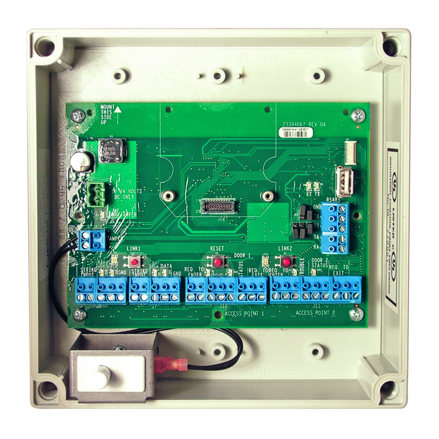
PANEL INTERFACE BOARD
Brand:
Schlage
| Category:
Computer Hardware
| Size: 0.54 MB
Table of Contents
Table of Contents
2
Overview
3
Getting Started
3
Handheld Device (HHD)
4
PIB300/PIB301 Installation
4
Location
4
Wiring to the Lock
4
Connect the PIB300/PIB301 to the Access Control Panel (ACP)
4
Cable/Wire Specifi Cations
5
Typical Wiring to the Access Control Panel
5
PIB300/PIB301 to ACP Connection
6
Complete the Installation
7
Access Point ACP Connections to a RS-485 Device Address
7
Reset to Factory Defaults
8
FCC Statements
8
Schlage PIB300 User Manual (8 pages)
Panel Interface Board
Brand:
Schlage
| Category:
Computer Hardware
| Size: 0.67 MB
Table of Contents
Table of Contents
2
Overview
3
Getting Started
3
Handheld Device (HHD)
3
PIB300 Installation
4
Location
4
Wiring to the Lock
4
Connecting the PIB300 to the Access Control Panel (ACP)
5
Cable/Wire Specifi Cations
5
Typical Wiring to the Access Control Panel
5
PIB300 to ACP Connection
6
Completing Installation
8
Access Point ACP Connections to a RS-485 Device Address
8
Resetting to Factory Defaults
8
Advertisement
Advertisement
Related Products
Schlage PIB301
Schlage PIM400-TD2
Schlage PIM-485-16-TD-NXT
Schlage PL Series
Schlage PIM400-485
Schlage PRO5100-FSA
Schlage PRO5100-FSE
Schlage PIM400-1501
Schlage PIM400
Schlage PIM85
Schlage Categories
Locks
Door locks
Card Reader
Keypad
Control Unit
More Schlage Manuals
Login
Sign In
OR
Sign in with Facebook
Sign in with Google
Upload manual
Upload from disk
Upload from URL