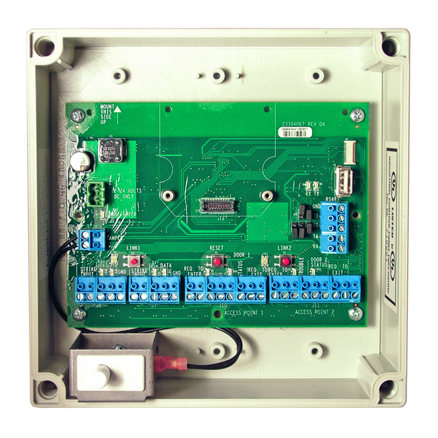
Summary of Contents for Schlage PIB300
- Page 1 P516-097 PIB300 and PIB301 USER GUIDE INSTALLATION AND OPERATION INSTRUCTIONS FOR PANEL INTERFACE BOARD...
-
Page 2: Table Of Contents
PIB300/PIB301 Installation ......................4 Location ............................. 4 Wiring to the Lock ........................4 Connect the PIB300/PIB301 to the Access Control Panel (ACP)..........4 Cable/Wire Specifi cations ......................5 Typical Wiring to the Access Control Panel ................5 PIB300/PIB301 to ACP Connection ....................6 Complete the Installation ....................... -
Page 3: Overview
• Provides two-way communication with locks via a RS-485 connection • The PIB300 may connect up to two Schlage AD-300 locks or up to two RS-485 based legacy locks communicating with the RSI or VIP protocol, may connect to an Access Control Panel (ACP) or reader interface board •... -
Page 4: Handheld Device (Hhd)
• Wiring of locks requires one connector via the RS-485 connector (J5). • Connections from lock to lock should be daisy-chained (see diagram below). • The power supply is located at or near the PIB300/PIB301 for short wire runs, or local to locks if located far from the panel. -
Page 5: Cable/Wire Specifi Cations
Notes: Only AP1 is shown connected. AP2 should be connected the same way. Unsupervised, ground switched inputs to panel shown. Some Access Control Panels require supervised inputs and/or “dry contact” isolated inputs. The optional Schlage RLBD is available for these applications. -
Page 6: Pib300/Pib301 To Acp Connection
Access Connector Signal Panel Signal Description/Explanation PIB300/PIB301 inputs for 12 or 24 VDC power. If the Access Control Panel (ACP) reader power outputs do not source enough current for the PIB300/PIB301, use the ACP main 12V+ 12 or 24 VDC... -
Page 7: Complete The Installation
Access Point ACP Connections to a RS-485 Device Address The PIB300/PIB301 Access Point to ACP connections are each associated with a RS-485 device address. This association is set using the Schlage Utility Software. Please see the SUS user manual for further information. -
Page 8: Reset To Factory Defaults
1. Remove the main cover. 2. Press and hold both link buttons for over 3 seconds. 3. Release both link buttons. The PIB300/PIB301 will blink the red lights beside each link button while confi guration reset takes place. 4. The two green lights beside the link buttons will blink 3 times when the reset is complete.


Need help?
Do you have a question about the PIB300 and is the answer not in the manual?
Questions and answers