Sign In
Upload
Manuals
Brands
ST Manuals
Microcontrollers
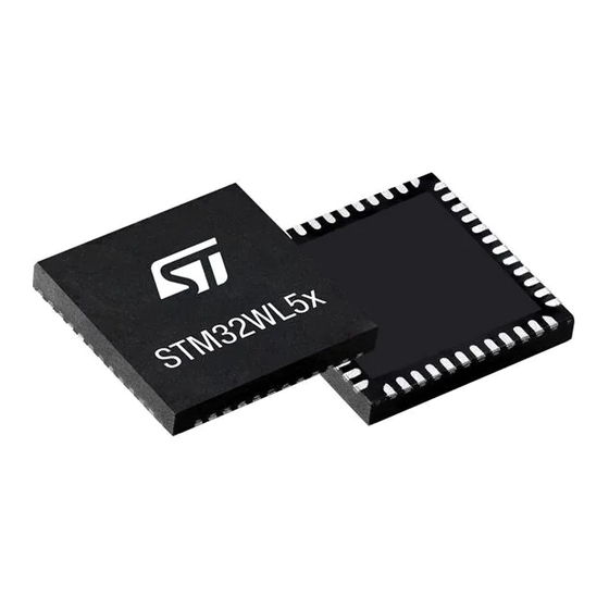
STM32WL55JC
ST STM32WL55JC Manuals
Manuals and User Guides for ST STM32WL55JC. We have
1
ST STM32WL55JC manual available for free PDF download: Reference Manual
ST STM32WL55JC Reference Manual (1454 pages)
Advanced Arm-based 32-bit MCUs with sub-GHz radio solution
Brand:
ST
| Category:
Microcontrollers
| Size: 29 MB
Table of Contents
Table of Contents
2
List of Tables
46
Documentation Conventions
60
General Information
60
List of Abbreviations for Registers
60
Availability of Peripherals
61
Glossary
61
Memory and Bus Architecture
62
System Architecture
62
Figure 1. System Architecture
63
S0: CPU1 I-Bus
63
S1: CPU1 D-Bus
63
S2: CPU1 S-Bus
63
S3: CPU2 S-Bus
63
Boot Configuration
64
S4, S5: DMA-Bus
64
Table 1. Device Boot Mode
64
CPU2 Boot
66
Memory Protection
67
SRAM Erase
67
Table 2. SRAM Erase Conditions
67
Figure 2. Memory Protection Example
69
Table 3. Memory Security and Privilege Access
70
Introduction
72
Memory Organization
72
Figure 3. Memory Map
73
Memory Map and Register Boundary Addresses
73
Table 4. Memory Map and Peripheral Register Boundary Addresses
74
CPU1 Bit Banding
77
Global Security Controller (GTZC)
79
GTZC Introduction
79
GTZC Main Features
79
GTZC Security System Architecture
79
Figure 4. GTZC Security Architecture
80
GTZC Block Diagram
80
GTZC Functional Description
80
Figure 5. GTZC Block Diagram
81
GTZC Internal Signals
81
Illegal Access Definition
81
Table 5. GTZC Internal Signals
81
Table 6. Memory Access Error Generation
83
Security Controller (TZSC)
84
Table 7. Peripheral Access Error Generation
84
Figure 6. Memory Protection Control Water Mark
85
Power-On/Reset State
85
Security Illegal Access Controller (TZIC)
85
GTZC TZSC Control Register (GTZC_TZSC_CR)
86
GTZC TZSC Registers
86
Interrupts
86
Table 8. TZSC Privileged Mpcwmn Register Memory Allocation
86
GTZC TZSC Security Configuration Register (GTZC_TZSC_SECCFGR1)
87
GTZC TZSC Privileged Configuration Register (GTZC_TZSC_PRIVCFGR1)
88
GTZC TZSC Unprivileged Watermark 1 Register (GTZC_TZSC_MPCWM1_UPWMR)
89
GTZC TZSC Unprivileged Writable Watermark 1 Register (GTZC_TZSC_MPCWM1_UPWWMR)
90
GTZC TZSC Unprivileged Watermark 2 Register (GTZC_TZSC_MPCWM2_UPWMR)
91
GTZC TZSC Unprivileged Watermark 3 Register (GTZC_TZSC_MPCWM3_UPWMR)
92
GTZC TZSC Register Map
93
Table 9. GTZC TZSC Register Map and Reset Values
93
GTZC TZIC Interrupt Enable Register 1 (GTZC_TZIC_IER1)
94
GTZC TZIC Registers
94
GTZC TZIC Status Register 1 (GTZC_TZIC_MISR1)
95
GTZC TZIC Interrupt Status Clear Register 1 (GTZC_TZIC_ICR1)
97
GTZC TZIC Register Map
98
Table 10. TZIC Register Map and Reset Values
98
Embedded Flash Memory (FLASH)
99
FLASH Functional Description
99
FLASH Introduction
99
FLASH Main Features
99
Flash Memory Organization
99
Empty Check
100
Table 11. Flash Memory - Single Bank Organization
100
Error Code Correction (ECC)
101
Read Access Latency
101
Table 12. Number of Wait States According to Flash Clock (HCLK3) Frequency
102
Adaptive Real-Time Memory Accelerator (ART Accelerator)
103
Figure 7. Sequential 16 Bits Instructions Execution
104
Flash Program and Erase Operations
106
Flash Main Memory Erase Sequences
107
Table 13. Page Erase Overview
107
Table 14. Mass Erase Overview
108
Flash Main Memory Programming Sequences
109
Table 15. Errors in Page-Based Row Programming
113
Flash Option Bytes
114
Option Bytes Description
114
Table 16. Option Bytes Organization
114
Option Bytes Programming
115
Table 17. Option Loading Control
117
Introduction
118
RSSLIB Functions
118
Secure System Memory
118
Sub-Ghz Radio SPI Security
118
Flash Memory Protection
119
Readout Protection (RDP)
119
Table 18. Flash Memory Readout Protection Status
119
Table 19. RDP Regression from Level 1 to Level 0 and Memory Erase
121
Figure 8. Changing the RDP Level
122
Table 20. Access Status Versus Protection Level and Execution Modes
122
Proprietary Code Readout Protection (PCROP)
123
Write Protection (WRP)
124
CPU2 Security (ESE)
125
CPU1 Boot Lock Chain of Trust
127
CPU2 Boot Lock Chain of Trust
127
FLASH Program Erase Suspension
127
Hide Protection Area (HDPAD)
127
FLASH Interrupts
128
Illegal Access Interrupts
128
Table 23. Flash Interrupt Requests
128
Register Access Protection
129
FLASH Access Control Register (FLASH_ACR)
130
FLASH Registers
130
FLASH Access Control Register 2 (FLASH_ACR2)
131
FLASH Key Register (FLASH_KEYR)
132
FLASH Option Key Register (FLASH_OPTKEYR)
132
FLASH Status Register (FLASH_SR)
133
FLASH Control Register (FLASH_CR)
135
FLASH ECC Register (FLASH_ECCR)
137
FLASH Option Register (FLASH_OPTR)
138
(Flash_Pcrop1Aer)
141
FLASH PCROP Zone a End Address Register
141
FLASH PCROP Zone a End Address Register (FLASH_PCROP1AER)
141
FLASH PCROP Zone a Start Address Register (FLASH_PCROP1ASR)
141
FLASH WRP Area a Address Register (FLASH_WRP1AR)
142
FLASH WRP Area B Address Register (FLASH_WRP1BR)
143
(Flash_Pcrop1Ber)
144
(Flash_Pcrop1Bsr)
144
FLASH PCROP Zone B End Address Register
144
FLASH PCROP Zone B End Address Register (FLASH_PCROP1BER)
144
FLASH PCROP Zone B Start Address Register
144
FLASH PCROP Zone B Start Address Register (FLASH_PCROP1BSR)
144
(Flash_Ipccbr)
145
FLASH IPCC Mailbox Data Buffer Address Register
145
FLASH IPCC Mailbox Data Buffer Address Register (FLASH_IPCCBR)
145
FLASH CPU2 Access Control Register (FLASH_C2ACR)
146
FLASH CPU2 Status Register (FLASH_C2SR)
146
FLASH CPU2 Control Register (FLASH_C2CR)
148
FLASH Secure Flash Start Address Register (FLASH_SFR)
150
(Flash_Srrvr)
151
FLASH Secure SRAM Start Address and CPU2 Reset Vector Register
151
FLASH Register Map
154
Table 25. Flash Interface Register Map and Reset Values
154
Sub-Ghz Radio (SUBGHZ)
156
Sub-Ghz Radio Introduction
156
Sub-Ghz Radio Main Features
156
Figure 9. Sub-Ghz Radio System Block Diagram
157
General Description
157
Sub-Ghz Radio Functional Description
157
Sub-Ghz Radio Signals
157
Table 26. Sub-Ghz Internal Input/Output Signals
157
Figure 10. High Output Power PA
158
Transmitter
158
Figure 11. Low Output Power PA
159
Receiver
159
Table 27. Sub-Ghz Radio Transmit High Output Power
159
Intermediate Frequencies
160
Rf-Pll
160
Table 28. FSK Mode Intermediate Frequencies
160
HSE32 Reference Clock
161
Internal Oscillators
161
Sub-Ghz Radio Clocks
161
Table 29. Lora Mode Intermediate Frequencies
161
Lora Modem
162
Sub-Ghz Radio Modems
162
Table 30. Spreading Factor, Chips/Symbol and Lora SNR
163
Table 31. Lora Bandwidth Setting
163
Lora Framing
164
Table 32. Coding Rate and Overhead Ratio
164
Figure 12. Lora Packet Frames Format
165
FSK Modem
166
Generic Framing
167
MSK Modem
167
Figure 13. Generic Packet Frames Format
168
BPSK Modem
169
BPSK Framing
170
Figure 14. Sub-Ghz RAM Data Buffer Operation
170
Sub-Ghz Radio Data Buffer
170
Receive Data Buffer Operation
171
Sub-Ghz Radio Operating Modes
171
Transmit Data Buffer Operation
171
Figure 15. Sub-Ghz Radio Operating Modes
172
Calibration Mode
173
Sleep Mode
173
Startup Mode
173
Frequency Synthesis Mode (FS)
174
Standby Mode
174
Transmit Mode (TX)
174
Active Mode Switching Time
175
Receive Mode (RX)
175
Figure 16. Sub-Ghz Radio BUSY Timing
176
Sub-Ghz Radio SPI Interface
176
Table 33. Operation Mode Transition BUSY Switching Time
176
Register and Buffer Access Commands
177
Sub-Ghz Radio Command Structure
177
Table 34. Command Structure
177
Operating Mode Commands
179
Figure 17. Receiver Listening Mode Timing
182
Sub-Ghz Radio Configuration Commands
184
Table 35. PA Optimal Setting and Operating Modes
186
Table 36. Recommended CAD Configuration Settings
188
Communication Status Information Commands
195
IRQ Interrupt Commands
198
Table 37. IRQ Bit Mapping and Definition
198
Miscellaneous Commands
200
Table 38. Image Calibration for ISM Bands
201
Set_Tcxomode Command
203
Table 39. Command Format Set_Tcxomode()
203
Sub-Ghz Radio Commands Overview
204
Table 40. Regtcxotrim and Timeout Bytes Definition
204
Table 41. Sub-Ghz Radio SPI Commands Overview
204
Basic Sequence for Lora, (G)MSK and (G)FSK Transmit Operation
206
Sub-Ghz Radio Application Configuration
206
Basic Sequence for Lora and (G)FSK Receive Operation
207
Basic Sequence for BPSK Transmit Operation
208
Sub-Ghz Radio Ramp-Up MSB Register (SUBGHZ_RAM_RAMPUPH)
208
Sub-Ghz Radio Registers
208
Sub-Ghz Radio Frame Limit MSB Register
209
Sub-Ghz Radio Ramp-Down LSB Register
209
Sub-Ghz Radio Ramp-Down MSB Register
209
Sub-Ghz Radio Ramp-Up LSB Register (SUBGHZ_RAM_RAMPUPL)
209
Sub-Ghz Radio Frame Limit LSB Register (SUBGHZ_RAM_FRAMELIML)
210
Sub-Ghz Radio Generic Bit Synchronization Register (SUBGHZ_GBSYNCR)
210
Sub-Ghz Radio Generic CFO MSB Register (SUBGHZ_GCFORH)
210
(Subghz_Gpktctl1Ar)
211
(Subghz_Gpktctl1R)
211
Sub-Ghz Radio Generic CFO LSB Register (SUBGHZ_GCFORL)
211
Sub-Ghz Radio Generic Packet Control 1 Register
211
Sub-Ghz Radio Generic Packet Control 1A Register
211
(Subghz_Grtxpldlen)
212
(Subghz_Gwhiteinirl)
212
Sub-Ghz Radio Generic Payload Length Register
212
Sub-Ghz Radio Generic Whitening LSB Register
212
Sub-Ghz Radio Random Number Register 1 (SUBGHZ_RNGR1)
219
Sub-Ghz Radio Random Number Register 2 (SUBGHZ_RNGR2)
219
Sub-Ghz Radio Random Number Register 3 (SUBGHZ_RNGR3)
219
(Subghz_Agcrssictl0R)
220
Sub-Ghz Radio AGC RSSI Control Register
220
Sub-Ghz Radio Random Number Register 0 (SUBGHZ_RNGR0)
220
Sub-Ghz Radio Receiver Gain Control Register (SUBGHZ_RXGAINCR)
220
Sub-Ghz Radio SD Resolution Register (SUBGHZ_SDCFG0R)
220
(Subghz_Agcgforstcfgr)
221
(Subghz_Agcgforstpowthr)
221
Sub-Ghz Radio AGC Reset Configuration Register
221
Sub-Ghz Radio AGC Reset Power Threshold Register
221
Sub-Ghz Radio Tx Clamp Register (SUBGHZ_TXCLAMPR)
221
(Subghz_Paocpr)
222
Sub-Ghz Radio Disable LNA Register (REG_ANA_LNA)
222
Sub-Ghz Radio Disable Mixer Register (REG_ANA_MIXER)
222
Sub-Ghz Radio PA over Current Protection Register
222
Sub-Ghz Radio RTC Control Register (SUBGHZ_RTCCTLR)
222
(Subghz_Rtcprdr1)
223
Sub-Ghz Radio RTC Period LSB Register (SUBGHZ_RTCPRDR0)
223
Sub-Ghz Radio RTC Period MID-Byte Register
223
Sub-Ghz Radio RTC Period MSB Register (SUBGHZ_RTCPRDR2)
223
(Subghz_Hseintrimr)
224
(Subghz_Hseouttrimr)
224
Sub-Ghz Radio HSE32 OSC_IN Capacitor Trim Register
224
Sub-Ghz Radio HSE32 OSC_OUT Capacitor Trim Register
224
Sub-Ghz Radio Power Control Register (SUBGHZ_PCR)
225
Sub-Ghz Radio SMPS Control 0 Register (SUBGHZ_SMPSC0R)
225
Sub-Ghz Radio SMPS Control 2 Register (SUBGHZ_SMPSC2R)
225
Sub-Ghz Radio Register Map
226
Sub-Ghz Radio RTC Control Register (SUBGHZ_EVENTMASKR)
226
Table 42. SUBGHZ Register Map and Reset Values
226
Power Control (PWR)
229
Power Supplies
229
Figure 18. Power Supply Overview
230
Figure 19. Supply Configurations
231
Battery Backup Domain
232
Independent Analog Peripherals Supply
232
Dynamic Voltage Scaling Management
234
Voltage Regulator
234
Brownout Reset (BOR)
235
Power Supply Supervisor
235
Power-On Reset (Por)/Power-Down Reset (PDR)
235
Figure 20. Brownout Reset Waveform
236
Programmable Voltage Detector (PVD)
236
Figure 21. PVD Thresholds
237
Peripheral Voltage Monitoring (PVM)
237
Table 43. PVM Features
237
Figure 22. EOL Thresholds
238
Radio Busy Management
238
Radio End of Life (EOL)
238
Figure 23. Radio Busy Management
239
CPU2 Boot
240
Figure 24. CPU2 Boot Options
241
Low-Power Modes
242
Figure 25. Cpus Low-Power Modes Possible Transitions
245
Table 44. Low-Power Mode Summary
246
Table 45. Functionalities Depending on System Operating Mode
247
Table 46. MCU and Sub-Ghz Radio Operating Modes
249
Low-Power Run Mode (Lprun)
250
Run Mode
250
Enter Low-Power Mode
251
Exit Low-Power Mode
251
Table 47. Lprun
251
Sleep Mode
253
Table 48. CPU Wakeup Versus System Operating Mode
253
Low-Power Sleep Mode (Lpsleep)
254
Table 49. Sleep Mode
254
Stop 0 Mode
255
Table 50. Lpsleep
255
Stop 1 Mode
257
Table 51. Stop 0 Mode
257
Stop 2 Mode
258
Table 52. Stop 1 Mode
258
Standby Mode
260
Table 53. Stop 2 Mode
260
Shutdown Mode
262
Table 54. Standby Mode
262
Auto-Wakeup from Low-Power Mode
263
Table 55. Shutdown Mode
263
PWR Control Register 1 (PWR_CR1)
264
PWR Registers
264
PWR Control Register 2 (PWR_CR2)
266
PWR Control Register 3 (PWR_CR3)
267
PWR Control Register 4 (PWR_CR4)
269
PWR Status Register 1 (PWR_SR1)
270
Power Status Register 2 (PWR_SR2)
271
PWR Status Clear Register (PWR_SCR)
273
PWR Control Register 5 (PWR_CR5)
274
PWR Port a Pull-Down Control Register (PWR_PDCRA)
275
PWR Port a Pull-Up Control Register (PWR_PUCRA)
275
PWR Port B Pull-Down Control Register (PWR_PDCRB)
276
PWR Port B Pull-Up Control Register (PWR_PUCRB)
276
PWR Port C Pull-Down Control Register (PWR_PDCRC)
277
PWR Port C Pull-Up Control Register (PWR_PUCRC)
277
PWR Port H Pull-Down Control Register (PWR_PDCRH)
278
PWR Port H Pull-Up Control Register (PWR_PUCRH)
278
PWR CPU2 Control Register 1 (PWR_C2CR1)
279
PWR CPU2 Control Register 3 (PWR_C2CR3)
280
PWR Extended Status and Status Clear Register (PWR_EXTSCR)
281
PWR Security Configuration Register (PWR_SECCFGR)
283
PWR Sub-Ghz SPI Control Register (PWR_SUBGHZSPICR)
283
PWR Register Map
284
PWR RSS Command Register (PWR_RSSCMDR)
284
Table 56. PWR Register Map and Reset Values
284
Power Reset
287
Reset
287
Reset and Clock Control (RCC)
287
System Reset
287
Figure 26. Simplified Diagram of the Reset Circuit
288
Backup Domain Reset
289
Clocks
289
PKA SRAM Reset
289
Sub-Ghz Radio Reset
289
Figure 27. Clock Tree
292
HSE32 Clock with Trimming
292
Figure 28. HSE32 Clock Sources
293
Figure 29. HSE32 TCXO Control
294
HSI16 Clock
295
MSI Clock
295
Pll
296
Figure 30. LSE Clock Sources
297
LSE Clock
297
Clock Source Stabilization Time
298
LSI Clock
298
System Clock (SYSCLK) Selection
298
Table 57. Clock Source Stabilization Times
298
Clock Security System on HSE32 (CSS)
299
Clock Source Frequency Versus Voltage Scaling
299
Table 58. Clock Source Frequency
299
Clock Security System on LSE (LSECSS)
300
SPI2S2 Clock
300
Sub-Ghz Radio SPI Clock
300
Table 59. SPI2S2 I2S Clock PLL Configurations
300
ADC Clock
301
RTC Clock
301
Table 60. Sub-Ghz Radio SPI Clock Configurations
301
Timer Clock
301
Clock-Out Capability
302
True RNG Clock
302
Watchdog Clock
302
Figure 31. Frequency Measurement with TIM16 in Capture Mode
303
Figure 32. Frequency Measurement with TIM17 in Capture Mode
303
Internal/External Clock Measurement with TIM16/TIM17
303
Peripheral Clocks Enable
305
Table 61. Peripheral Clock Enable
305
Table 62. Low-Power Debug Configurations
306
Table 63. RCC Register Map and Reset Values
367
Figure 33. HSEM Block Diagram
374
Table 64. HSEM Internal Input/Output Signals
374
Figure 34. Procedure State Diagram
375
Figure 35. Interrupt State Diagram
378
Table 65. Authorized AHB Bus Master Ids
379
Table 66. HSEM Register Map and Reset Values
385
Figure 36. IPCC Block Diagram
388
Table 67. IPCC Interface Signals
388
Figure 37. IPCC Simplex Channel Mode Transfer Timing
389
Table 68. Bits Used for the Communication
389
Figure 38. IPCC Simplex - Send Procedure State Diagram
390
Figure 39. IPCC Simplex - Receive Procedure State Diagram
391
Figure 40. IPCC Half-Duplex Channel Mode Transfer Timing
392
Figure 41. IPCC Half-Duplex - Send Procedure State Diagram
392
Figure 42. IPCC Half-Duplex - Receive Procedure State Diagram
393
Table 69. IPCC Register Map and Reset Values
400
Figure 43. Basic Structure of a Standard I/O Port Bit
402
Figure 44. Basic Structure of a 5V-Tolerant I/O Port Bit
403
Table 70. Port Bit Configurations
403
Figure 45. Input Floating/Pull-Up/Pull-Down Configurations
407
Figure 46. Output Configuration
408
Figure 47. Alternate Function Configuration
408
Figure 48. High Impedance Analog Configuration
409
Table 71. GPIOA Register Map and Reset Values
429
Table 72. GPIOB Register Map and Reset Values
430
Table 73. GPIOC Register Map and Reset Values
431
Table 74. GPIOH Register Map and Reset Values
432
Table 75. SYSCFG Register Map and Reset Values
445
Table 76. Stm32Wl5X Peripherals Interconnect Matrix
447
Table 77. DMA1 and DMA2 Implementation
456
Figure 49. DMA Block Diagram
457
Table 78. DMA Internal Input/Output Signals
458
Table 79. Programmable Data Width and Endian Behavior (When PINC = MINC = 1)
465
Table 80. DMA Interrupt Requests
467
Table 81. DMA Register Map and Reset Values
478
Table 82. DMAMUX Instantiation
482
Table 83. DMAMUX1: Assignment of Multiplexer Inputs to Resources
483
Table 84. DMAMUX1: Assignment of Trigger Inputs to Resources
484
Table 85. DMAMUX1: Assignment of Synchronization Inputs to Resources
484
Figure 50. DMAMUX Block Diagram
485
Table 86. DMAMUX Signals
486
Figure 51. Synchronization Mode of the DMAMUX Request Line Multiplexer Channel
489
Figure 52. Event Generation of the DMA Request Line Multiplexer Channel
489
Table 87. DMAMUX Interrupts
491
Table 88. DMAMUX Register Map and Reset Values
498
Figure 53. Interrupt Block Diagram
501
Table 89. CPU1 Vector Table
501
Table 90. CPU2 Vector Table
504
Figure 54. EXTI Block Diagram
508
Table 91. EXTI Pin Overview
508
Table 92. EVG Pin Overview
508
Table 93. Wakeup Interrupts
509
Table 94. EXTI Event Input Configurations and Register Control
511
Figure 55. Configurable Event Trigger Logic CPU Wakeup
512
Figure 56. Direct Event Trigger Logic CPU Wakeup
513
Table 95. Masking Functionality
513
Table 96. EXTI Register Map Sections
514
Table 97. EXTI Register Map and Reset Values
524
Figure 57. CRC Calculation Unit Block Diagram
527
Table 98. CRC Internal Input/Output Signals
527
Table 99. CRC Register Map and Reset Values
532
Figure 58. ADC Block Diagram
535
Table 100. ADC Input/Output Pins
535
Table 101. ADC Internal Input/Output Signals
536
Table 102. External Triggers
536
Figure 59. ADC Calibration
538
Figure 60. Calibration Factor Forcing
538
Figure 61. Enabling/Disabling the ADC
539
Figure 62. ADC Clock Scheme
540
Table 103. Latency between Trigger and Start of Conversion
541
Figure 63. ADC Connectivity
542
Figure 64. Analog to Digital Conversion Time
547
Figure 65. ADC Conversion Timings
547
Figure 66. Stopping an Ongoing Conversion
548
Table 104. Configuring the Trigger Polarity
548
Table 105. Tsar Timings Depending on Resolution
550
Figure 67. Single Conversions of a Sequence, Software Trigger
551
Figure 68. Continuous Conversion of a Sequence, Software Trigger
551
Figure 69. Single Conversions of a Sequence, Hardware Trigger
552
Figure 70. Continuous Conversions of a Sequence, Hardware Trigger
552
Figure 71. Data Alignment and Resolution (Oversampling Disabled: OVSE = 0)
553
Figure 72. Example of Overrun (OVR)
554
Figure 73. Wait Mode Conversion (Continuous Mode, Software Trigger)
557
Figure 74. Behavior with WAIT = 0, AUTOFF = 1
558
Figure 76. Analog Watchdog Guarded Area
559
Table 106. Analog Watchdog Comparison
559
Table 107. Analog Watchdog 1 Channel Selection
559
Figure 77. Adc_Awdx_Out Signal Generation
561
Figure 78. Adc_Awdx_Out Signal Generation (Awdx Flag Not Cleared by Software)
561
Figure 79. Adc_Awdx_Out Signal Generation (on a Single Channel)
562
Figure 80. Analog Watchdog Threshold Update
562
Figure 81. 20-Bit to 16-Bit Result Truncation
563
Figure 82. Numerical Example with 5-Bits Shift and Rounding
564
Table 108. Maximum Output Results Vs N and M. Grayed Values Indicates Truncation
564
Figure 83. Triggered Oversampling Mode (TOVS Bit = 1)
566
Figure 84. Temperature Sensor and VREFINT Channel Block Diagram
567
Figure 85. VBAT Channel Block Diagram
569
Table 109. ADC Interrupts
569
Table 110. ADC Register Map and Reset Values
590
Figure 86. DAC Block Diagram
594
Table 111. DAC Features
594
Table 112. DAC Input/Output Pins
595
Table 113. DAC Internal Input/Output Signals
595
Table 114. DAC Interconnection
595
Figure 87. Data Registers in Single DAC Channel Mode
596
Figure 88. Timing Diagram for Conversion with Trigger Disabled TEN = 0
597
Figure 89. DAC LFSR Register Calculation Algorithm
599
Figure 90. DAC Conversion (SW Trigger Enabled) with LFSR Wave Generation
599
Figure 91. DAC Triangle Wave Generation
600
Figure 92. DAC Conversion (SW Trigger Enabled) with Triangle Wave Generation
600
Table 115. Sample and Refresh Timings
602
Figure 93. DAC Sample and Hold Mode Phase Diagram
603
Table 116. Channel Output Modes Summary
603
Table 117. Effect of Low-Power Modes on DAC
606
Table 118. DAC Interrupts
607
Table 119. DAC Register Map and Reset Values
617
Table 120. VREF Buffer Modes
619
Table 121. VREFBUF Register Map and Reset Values
621
Figure 94. Comparator Block Diagram
623
Table 122. COMP1 Input Plus Assignment
623
Table 123. COMP1 Input Minus Assignment
624
Table 124. COMP2 Input Plus Assignment
624
Table 125. COMP2 Input Minus Assignment
624
Figure 95. Window Mode
626
Figure 96. Comparator Hysteresis
626
Figure 97. Comparator Output Blanking
627
Table 126. Comparator Behavior in the Low-Power Modes
628
Table 127. Interrupt Control Bits
628
Table 128. COMP Register Map and Reset Values
633
Figure 98. RNG Block Diagram
635
Table 129. RNG Internal Input/Output Signals
635
Figure 99. NIST SP800-90B Entropy Source Model
636
Figure 100. RNG Initialization Overview
639
Table 130. RNG Interrupt Requests
643
Table 131. RNG Configurations
644
Table 132. RNG Register Map and Reset Map
649
Figure 101. AES Block Diagram
651
Table 133. AES Internal Input/Output Signals
651
Figure 102. ECB Encryption and Decryption Principle
653
Figure 103. CBC Encryption and Decryption Principle
654
Figure 104. CTR Encryption and Decryption Principle
655
Figure 105. GCM Encryption and Authentication Principle
656
Figure 106. GMAC Authentication Principle
656
Figure 107. CCM Encryption and Authentication Principle
657
Figure 108. Example of Suspend Mode Management
661
Figure 109. ECB Encryption
662
Figure 110. ECB Decryption
662
Figure 111. CBC Encryption
663
Figure 112. CBC Decryption
663
Figure 113. ECB/CBC Encryption (Mode 1)
664
Figure 114. ECB/CBC Decryption (Mode 3)
665
Figure 115. Message Construction in CTR Mode
666
Figure 116. CTR Encryption
667
Figure 117. CTR Decryption
667
Table 134. CTR Mode Initialization Vector Definition
667
Figure 118. Message Construction in GCM
669
Table 135. GCM Last Block Definition
669
Figure 119. GCM Authenticated Encryption
670
Table 136. Initialization of Aes_Ivrx Registers in GCM Mode
670
Figure 120. Message Construction in GMAC Mode
674
Figure 121. GMAC Authentication Mode
674
Figure 122. Message Construction in CCM Mode
675
Figure 123. CCM Mode Authenticated Encryption
677
Table 137. Initialization of Aes_Ivrx Registers in CCM Mode
677
Figure 124. 128-Bit Block Construction with Respect to Data Swap
681
Table 138. Key Endianness in Aes_Keyrx Registers (128- or 256-Bit Key Length)
682
Figure 125. DMA Transfer of a 128-Bit Data Block During Input Phase
683
Figure 126. DMA Transfer of a 128-Bit Data Block During Output Phase
684
Table 139. AES Interrupt Requests
685
Table 140. Processing Latency for ECB, CBC and CTR
685
Table 141. Processing Latency for GCM and CCM (in Clock Cycles)
686
Table 142. AES Register Map and Reset Values
696
Figure 127. PKA Block Diagram
699
Table 143. Internal Input/Output Signals
699
Table 144. PKA Integer Arithmetic Functions List
700
Table 145. PKA Prime Field (Fp) Elliptic Curve Functions List
700
Table 146. Montgomery Parameter Computation
705
Table 147. Modular Addition
706
Table 148. Modular Subtraction
706
Table 149. Montgomery Multiplication
707
Table 150. Modular Exponentiation (Normal Mode)
708
Table 151. Modular Exponentiation (Fast Mode)
708
Table 152. Modular Inversion
708
Table 153. Modular Reduction
709
Table 154. Arithmetic Addition
709
Table 155. Arithmetic Subtraction
709
Table 156. Arithmetic Multiplication
710
Table 157. Arithmetic Comparison
710
Table 158. CRT Exponentiation
711
Table 159. Point on Elliptic Curve Fp Check
712
Table 160. ECC Fp Scalar Multiplication
712
Table 161. ECC Fp Scalar Multiplication (Fast Mode)
713
Table 162. ECDSA Sign - Inputs
714
Table 163. ECDSA Sign - Outputs
714
Table 164. Extended ECDSA Sign (Extra Outputs)
715
Table 165. ECDSA Verification (Inputs)
715
Table 166. ECDSA Verification (Outputs)
715
Table 167. Family of Supported Curves for ECC Operations
716
Table 168. Modular Exponentiation Computation Times
718
Table 169. ECC Scalar Multiplication Computation Times
718
Table 170. ECDSA Signature Average Computation Times
718
Table 171. ECDSA Verification Average Computation Times
719
Table 172. Point on Elliptic Curve Fp Check Average Computation Times
719
Table 173. Montgomery Parameters Average Computation Times
719
Table 174. PKA Interrupt Requests
719
Table 175. PKA Register Map and Reset Values
723
Figure 128. Advanced-Control Timer Block Diagram
726
Figure 129. Counter Timing Diagram with Prescaler Division Change from 1 to 2
728
Figure 130. Counter Timing Diagram with Prescaler Division Change from 1 to 4
728
Figure 131. Counter Timing Diagram, Internal Clock Divided by 1
730
Figure 132. Counter Timing Diagram, Internal Clock Divided by 2
730
Figure 133. Counter Timing Diagram, Internal Clock Divided by 4
731
Figure 134. Counter Timing Diagram, Internal Clock Divided by N
731
Figure 135. Counter Timing Diagram, Update Event When ARPE=0 (Timx_Arr Not Preloaded)
732
Figure 136. Counter Timing Diagram, Update Event When ARPE=1 (Timx_Arr Preloaded)
732
Figure 137. Counter Timing Diagram, Internal Clock Divided by 1
734
Figure 138. Counter Timing Diagram, Internal Clock Divided by 2
734
Figure 139. Counter Timing Diagram, Internal Clock Divided by 4
735
Figure 140. Counter Timing Diagram, Internal Clock Divided by N
735
Figure 141. Counter Timing Diagram, Update Event When Repetition Counter Is Not Used
736
Figure 142. Counter Timing Diagram, Internal Clock Divided by 1, Timx_Arr = 0X6
737
Figure 143. Counter Timing Diagram, Internal Clock Divided by 2
738
Figure 144. Counter Timing Diagram, Internal Clock Divided by 4, Timx_Arr=0X36
738
Figure 145. Counter Timing Diagram, Internal Clock Divided by N
739
Figure 146. Counter Timing Diagram, Update Event with ARPE=1 (Counter Underflow)
739
Figure 147. Counter Timing Diagram, Update Event with ARPE=1 (Counter Overflow)
740
Figure 148. Update Rate Examples Depending on Mode and Timx_Rcr Register Settings
741
Figure 149. External Trigger Input Block
742
Figure 151. Control Circuit in Normal Mode, Internal Clock Divided by 1
743
Figure 152. TI2 External Clock Connection Example
744
Figure 153. Control Circuit in External Clock Mode 1
745
Figure 154. External Trigger Input Block
745
Figure 155. Control Circuit in External Clock Mode 2
746
Figure 156. Capture/Compare Channel (Example: Channel 1 Input Stage)
747
Figure 157. Capture/Compare Channel 1 Main Circuit
747
Figure 158. Output Stage of Capture/Compare Channel (Channel 1, Idem Ch. 2 and 3)
748
Figure 159. Output Stage of Capture/Compare Channel (Channel 4)
748
Figure 160. Output Stage of Capture/Compare Channel (Channel 5, Idem Ch. 6)
749
Figure 161. PWM Input Mode Timing
751
Figure 162. Output Compare Mode, Toggle on OC1
753
Figure 163. Edge-Aligned PWM Waveforms (ARR=8)
754
Figure 164. Center-Aligned PWM Waveforms (ARR=8)
755
Figure 165. Generation of 2 Phase-Shifted PWM Signals with 50% Duty Cycle
757
Figure 166. Combined PWM Mode on Channel 1 and 3
758
Figure 167. 3-Phase Combined PWM Signals with Multiple Trigger Pulses Per Period
759
Figure 168. Complementary Output with Dead-Time Insertion
760
Figure 169. Dead-Time Waveforms with Delay Greater than the Negative Pulse
760
Figure 170. Dead-Time Waveforms with Delay Greater than the Positive Pulse
761
Figure 171. Break and Break2 Circuitry Overview
763
Figure 172. Various Output Behavior in Response to a Break Event on BRK (OSSI = 1)
765
Figure 173. PWM Output State Following BRK and BRK2 Pins Assertion (OSSI=1)
766
Table 176. Behavior of Timer Outputs Versus BRK/BRK2 Inputs
766
Figure 174. PWM Output State Following BRK Assertion (OSSI=0)
767
Figure 175. Output Redirection (BRK2 Request Not Represented)
768
Table 177. Break Protection Disarming Conditions
768
Figure 176. Clearing Timx Ocxref
769
Figure 177. 6-Step Generation, COM Example (OSSR=1)
770
Figure 178. Example of One Pulse Mode
771
Figure 179. Retriggerable One Pulse Mode
773
Figure 180. Example of Counter Operation in Encoder Interface Mode
774
Table 178. Counting Direction Versus Encoder Signals
774
Figure 181. Example of Encoder Interface Mode with TI1FP1 Polarity Inverted
775
Figure 182. Measuring Time Interval between Edges on 3 Signals
776
Figure 183. Example of Hall Sensor Interface
778
Figure 184. Control Circuit in Reset Mode
779
Figure 185. Control Circuit in Gated Mode
780
Figure 186. Control Circuit in Trigger Mode
781
Figure 187. Control Circuit in External Clock Mode 2 + Trigger Mode
782
Table 179. TIM1 Internal Trigger Connection
791
Table 180. Output Control Bits for Complementary Ocx and Ocxn Channels with Break Feature
805
Table 181. TIM1 Register Map and Reset Values
822
Figure 188. General-Purpose Timer Block Diagram
826
Figure 189. Counter Timing Diagram with Prescaler Division Change from 1 to 2
828
Figure 190. Counter Timing Diagram with Prescaler Division Change from 1 to 4
828
Figure 191. Counter Timing Diagram, Internal Clock Divided by 1
829
Figure 192. Counter Timing Diagram, Internal Clock Divided by 2
830
Figure 193. Counter Timing Diagram, Internal Clock Divided by 4
830
Figure 194. Counter Timing Diagram, Internal Clock Divided by N
831
Figure 195. Counter Timing Diagram, Update Event When ARPE=0 (Timx_Arr Not Preloaded)
831
Figure 196. Counter Timing Diagram, Update Event When ARPE=1 (Timx_Arr Preloaded)
832
Figure 197. Counter Timing Diagram, Internal Clock Divided by 1
833
Figure 198. Counter Timing Diagram, Internal Clock Divided by 2
833
Figure 199. Counter Timing Diagram, Internal Clock Divided by 4
834
Figure 200. Counter Timing Diagram, Internal Clock Divided by N
834
Figure 201. Counter Timing Diagram, Update Event When Repetition Counter
835
Is Not Used
835
Figure 202. Counter Timing Diagram, Internal Clock Divided by 1, Timx_Arr=0X6
836
Figure 203. Counter Timing Diagram, Internal Clock Divided by 2
837
Figure 204. Counter Timing Diagram, Internal Clock Divided by 4, Timx_Arr=0X36
837
Figure 205. Counter Timing Diagram, Internal Clock Divided by N
838
Figure 206. Counter Timing Diagram, Update Event with ARPE=1 (Counter Underflow)
838
Figure 207. Counter Timing Diagram, Update Event with ARPE=1 (Counter Overflow)
839
Figure 208. Control Circuit in Normal Mode, Internal Clock Divided by 1
840
Figure 209. TI2 External Clock Connection Example
840
Figure 210. Control Circuit in External Clock Mode 1
841
Figure 211. External Trigger Input Block
842
Figure 212. Control Circuit in External Clock Mode 2
843
Figure 213. Capture/Compare Channel (Example: Channel 1 Input Stage)
843
Figure 214. Capture/Compare Channel 1 Main Circuit
844
Figure 215. Output Stage of Capture/Compare Channel (Channel 1)
844
Figure 216. PWM Input Mode Timing
846
Figure 217. Output Compare Mode, Toggle on OC1
848
Figure 218. Edge-Aligned PWM Waveforms (ARR=8)
849
Figure 219. Center-Aligned PWM Waveforms (ARR=8)
851
Figure 220. Generation of 2 Phase-Shifted PWM Signals with 50% Duty Cycle
852
Figure 221. Combined PWM Mode on Channels 1 and 3
853
Figure 222. Clearing Timx Ocxref
854
Figure 223. Example of One-Pulse Mode
855
Figure 224. Retriggerable One-Pulse Mode
857
Figure 225. Example of Counter Operation in Encoder Interface Mode
858
Table 182. Counting Direction Versus Encoder Signals
858
Figure 226. Example of Encoder Interface Mode with TI1FP1 Polarity Inverted
859
Figure 227. Control Circuit in Reset Mode
860
Figure 228. Control Circuit in Gated Mode
861
Figure 229. Control Circuit in Trigger Mode
862
Figure 230. Control Circuit in External Clock Mode 2 + Trigger Mode
863
Figure 231. Master/Slave Timer Example
863
Figure 232. Master/Slave Connection Example with 1 Channel Only Timers
864
Figure 233. Gating TIM2 with OC1REF of TIM1
865
Figure 234. Gating TIM2 with Enable of TIM1
866
Figure 235. Triggering TIM2 with Update of TIM1
866
Figure 236. Triggering TIM2 with Enable of TIM1
867
Table 183. TIM2 Internal Trigger Connection
875
Table 184. Output Control Bit for Standard Ocx Channels
886
Table 185. TIM2 Register Map and Reset Values
893
Figure 237. TIM16/TIM17 Block Diagram
897
Figure 238. Counter Timing Diagram with Prescaler Division Change from 1 to 2
899
Figure 239. Counter Timing Diagram with Prescaler Division Change from 1 to 4
899
Figure 240. Counter Timing Diagram, Internal Clock Divided by 1
901
Figure 241. Counter Timing Diagram, Internal Clock Divided by 2
901
Figure 242. Counter Timing Diagram, Internal Clock Divided by 4
902
Figure 243. Counter Timing Diagram, Internal Clock Divided by N
902
Preloaded)
903
Figure 246. Update Rate Examples Depending on Mode and Timx_Rcr Register Settings
905
Figure 247. Control Circuit in Normal Mode, Internal Clock Divided by 1
906
Figure 248. TI2 External Clock Connection Example
906
Figure 249. Control Circuit in External Clock Mode 1
907
Figure 250. Capture/Compare Channel (Example: Channel 1 Input Stage)
908
Figure 251. Capture/Compare Channel 1 Main Circuit
908
Figure 252. Output Stage of Capture/Compare Channel (Channel 1)
909
Figure 253. Output Compare Mode, Toggle on OC1
912
Figure 254. Edge-Aligned PWM Waveforms (ARR=8)
913
Figure 255. Complementary Output with Dead-Time Insertion
914
Figure 256. Dead-Time Waveforms with Delay Greater than the Negative Pulse
914
Figure 257. Dead-Time Waveforms with Delay Greater than the Positive Pulse
915
Figure 258. Output Behavior in Response to a Break
917
Table 186. Break Protection Disarming Conditions
918
Figure 259. Output Redirection
919
Figure 260. 6-Step Generation, COM Example (OSSR=1)
920
Figure 261. Example of One Pulse Mode
922
(Tim16/17)
935
Table 187. Output Control Bits for Complementary Ocx and Ocxn Channels with Break Feature
935
Table 188. TIM16/TIM17 Register Map and Reset Values
946
Figure 262. Low-Power Timer Block Diagram
949
Table 189. Stm32Wl5X LPTIM Features
949
Table 190. LPTIM Input/Output Pins
950
Table 191. LPTIM Internal Signals
950
Table 192. LPTIM1 External Trigger Connection
950
Table 193. LPTIM2 External Trigger Connection
951
Table 194. LPTIM3 External Trigger Connection
951
Table 195. LPTIM1 Input 1 Connection
951
Table 196. LPTIM1 Input 2 Connection
951
Table 197. LPTIM2 Input 1 Connection
952
Table 198. LPTIM3 Input 1 Connection
952
Figure 263. Glitch Filter Timing Diagram
953
Table 199. Prescaler Division Ratios
953
And Set-Once Mode Activated (WAVE Bit Is Set)
955
Figure 264. LPTIM Output Waveform, Single Counting Mode Configuration When Repetition Register Content Is Different than Zero (with PRELOAD = 1)
955
Figure 266. LPTIM Output Waveform, Continuous Counting Mode Configuration
956
Figure 267. Waveform Generation
957
Table 200. Encoder Counting Scenarios
960
Figure 268. Encoder Mode Counting Sequence
961
Different from Zero (with PRELOAD = 1)
962
Table 201. Effect of Low-Power Modes on the LPTIM
963
Table 202. Interrupt Events
963
Table 203. LPTIM Register Map and Reset Values
975
Figure 270. IRTIM Internal Hardware Connections with TIM16 and TIM17
977
Figure 271. Independent Watchdog Block Diagram
978
Table 204. IWDG Register Map and Reset Values
986
Figure 272. Watchdog Block Diagram
988
Table 205. WWDG Internal Input/Output Signals
988
Figure 273. Window Watchdog Timing Diagram
989
Table 206. WWDG Register Map and Reset Values
992
Table 207. RTC Input/Output Pins
995
Table 208. RTC Internal Input/Output Signals
995
Table 209. RTC Interconnection
996
Table 210. PC13 Configuration
996
Table 211. RTC_OUT Mapping
998
Table 212. Effect of Low-Power Modes on RTC
1011
Table 213. RTC Pins Functionality over Modes
1011
Table 214. Interrupt Requests
1012
Table 215. RTC Register Map and Reset Values
1034
Figure 275. TAMP Block Diagram
1037
Table 216. TAMP Input/Output Pins
1038
Table 217. TAMP Internal Input/Output Signals
1038
Table 218. TAMP Interconnection
1038
Table 219. Effect of Low-Power Modes on TAMP
1041
Table 220. Interrupt Requests
1041
Table 221. TAMP Register Map and Reset Values
1052
Table 222. Stm32Wl5X I2C Implementation
1054
Figure 276. I2C Block Diagram
1055
Table 223. I2C Input/Output Pins
1056
Table 224. I2C Internal Input/Output Signals
1056
Figure 277. I2C Bus Protocol
1057
Table 225. Comparison of Analog Vs. Digital Filters
1058
Figure 278. Setup and Hold Timings
1059
Table 226. I2C-Smbus Specification Data Setup and Hold Times
1061
Figure 279. I2C Initialization Flow
1062
Figure 280. Data Reception
1063
Figure 281. Data Transmission
1064
Table 227. I2C Configuration
1065
Figure 282. Slave Initialization Flow
1067
Figure 283. Transfer Sequence Flow for I2C Slave Transmitter, NOSTRETCH = 0
1069
Figure 284. Transfer Sequence Flow for I2C Slave Transmitter, NOSTRETCH = 1
1070
Figure 285. Transfer Bus Diagrams for I2C Slave Transmitter
1071
Figure 286. Transfer Sequence Flow for Slave Receiver with NOSTRETCH = 0
1072
Figure 287. Transfer Sequence Flow for Slave Receiver with NOSTRETCH = 1
1073
Figure 288. Transfer Bus Diagrams for I2C Slave Receiver
1073
Figure 289. Master Clock Generation
1075
Table 228. I2C-Smbus Specification Clock Timings
1076
Figure 290. Master Initialization Flow
1077
Figure 291. 10-Bit Address Read Access with HEAD10R = 0
1077
Figure 292. 10-Bit Address Read Access with HEAD10R = 1
1078
Figure 293. Transfer Sequence Flow for I2C Master Transmitter for N≤255 Bytes
1079
Figure 294. Transfer Sequence Flow for I2C Master Transmitter for N>255 Bytes
1080
Figure 295. Transfer Bus Diagrams for I2C Master Transmitter
1081
Figure 296. Transfer Sequence Flow for I2C Master Receiver for N≤255 Bytes
1083
Figure 297. Transfer Sequence Flow for I2C Master Receiver for N >255 Bytes
1084
Figure 298. Transfer Bus Diagrams for I2C Master Receiver
1085
Table 229. Examples of Timing Settings for Fi2Cclk = 8 Mhz
1086
Table 230. Examples of Timings Settings for Fi2Cclk = 16 Mhz
1086
Figure 299. Timeout Intervals for T
1089
LOW:SEXT , T LOW:MEXT
1089
Table 231. Smbus Timeout Specifications
1089
Table 232. Smbus with PEC Configuration
1091
(Max T IDLE = 50 Μs)
1092
(Max T TIMEOUT = 25 Ms)
1092
Table 233. Examples of TIMEOUTA Settings for Various I2CCLK Frequencies
1092
Table 234. Examples of TIMEOUTB Settings for Various I2CCLK Frequencies
1092
Figure 300. Transfer Sequence Flow for Smbus Slave Transmitter N Bytes + PEC
1093
Figure 301. Transfer Bus Diagrams for Smbus Slave Transmitter (SBC=1)
1093
Figure 302. Transfer Sequence Flow for Smbus Slave Receiver N Bytes + PEC
1095
Figure 303. Bus Transfer Diagrams for Smbus Slave Receiver (SBC=1)
1096
Figure 304. Bus Transfer Diagrams for Smbus Master Transmitter
1097
Figure 305. Bus Transfer Diagrams for Smbus Master Receiver
1099
Table 236. Effect of Low-Power Modes on the I2C
1103
Table 237. I2C Interrupt Requests
1104
Table 238. I2C Register Map and Reset Values
1119
Table 239. USART / LPUART Features
1123
Figure 306. USART Block Diagram
1124
Figure 307. Word Length Programming
1127
Figure 308. Configurable Stop Bits
1129
Figure 310. Start Bit Detection When Oversampling by 16 or 8
1133
Figure 311. Usart_Ker_Ck Clock Divider Block Diagram
1136
Figure 312. Data Sampling When Oversampling by 16
1137
Figure 313. Data Sampling When Oversampling by 8
1138
Table 240. Noise Detection from Sampled Data
1138
Table 241. Tolerance of the USART Receiver When BRR [3:0] = 0000
1141
Table 242. Tolerance of the USART Receiver When BRR[3:0] Is Different from 0000
1142
Figure 314. Mute Mode Using Idle Line Detection
1145
Figure 315. Mute Mode Using Address Mark Detection
1146
Table 243. USART Frame Formats
1147
Figure 316. Break Detection in LIN Mode (11-Bit Break Length - LBDL Bit Is Set)
1149
Figure 317. Break Detection in LIN Mode Vs. Framing Error Detection
1150
(M Bits = 00)
1151
Figure 318. USART Example of Synchronous Master Transmission
1151
Figure 319. USART Data Clock Timing Diagram in Synchronous Master Mode
1151
(M Bits = 01)
1152
(M Bits = 00)
1153
Figure 321. USART Data Clock Timing Diagram in Synchronous Slave Mode
1153
Figure 322. ISO 7816-3 Asynchronous Protocol
1155
Figure 323. Parity Error Detection Using the 1.5 Stop Bits
1157
Figure 324. Irda SIR ENDEC Block Diagram
1161
Figure 325. Irda Data Modulation (3/16) - Normal Mode
1161
Figure 326. Transmission Using DMA
1163
Figure 327. Reception Using DMA
1164
Figure 328. Hardware Flow Control between 2 Usarts
1164
Figure 329. RS232 RTS Flow Control
1165
Figure 330. RS232 CTS Flow Control
1166
FIFO Disabled)
1169
Figure 331. Wakeup Event Verified (Wakeup Event = Address Match, FIFO Disabled)
1169
Figure 332. Wakeup Event Not Verified
1169
Table 244. Effect of Low-Power Modes on the USART
1170
Table 245. USART Interrupt Requests
1171
Table 246. USART Register Map and Reset Values
1206
Table 247. USART / LPUART Features
1210
Figure 333. LPUART Block Diagram
1211
Figure 334. LPUART Word Length Programming
1213
Figure 335. Configurable Stop Bits
1215
Figure 337. Lpuart_Ker_Ck Clock Divider Block Diagram
1220
Table 248. Error Calculation for Programmed Baud Rates at Lpuart_Ker_Ck_Pres = 32.768 Khz
1221
Table 249. Error Calculation for Programmed Baud Rates at Fck = 100 Mhz
1222
Table 250. Tolerance of the LPUART Receiver
1223
Figure 338. Mute Mode Using Idle Line Detection
1224
Figure 339. Mute Mode Using Address Mark Detection
1225
Figure 340. Transmission Using DMA
1227
Figure 341. Reception Using DMA
1228
Figure 342. Hardware Flow Control between 2 Lpuarts
1229
Figure 343. RS232 RTS Flow Control
1229
Figure 344. RS232 CTS Flow Control
1230
FIFO Disabled)
1233
Figure 345. Wakeup Event Verified
1233
Figure 346. Wakeup Event Not Verified
1233
Table 252. Effect of Low-Power Modes on the LPUART
1234
Table 253. LPUART Interrupt Requests
1235
Table 254. LPUART Register Map and Reset Values
1259
Table 255. Stm32Wl5X SPI and SPI/I2S Implementation
1262
Figure 347. SPI Block Diagram
1263
Figure 348. Full-Duplex Single Master/ Single Slave Application
1264
Figure 349. Half-Duplex Single Master/ Single Slave Application
1265
Figure 350. Simplex Single Master/Single Slave Application
1266
Slave in Receive-Only Mode)
1266
Figure 351. Master and Three Independent Slaves
1267
Figure 352. Multi-Master Application
1268
Figure 353. Hardware/Software Slave Select Management
1269
Figure 354. Data Clock Timing Diagram
1270
Figure 355. Data Alignment When Data Length Is Not Equal to 8-Bit or 16-Bit
1271
Figure 356. Packing Data in FIFO for Transmission and Reception
1275
Figure 357. Master Full-Duplex Communication
1278
Figure 358. Slave Full-Duplex Communication
1279
Figure 359. Master Full-Duplex Communication with CRC
1280
Figure 360. Master Full-Duplex Communication in Packed Mode
1281
Figure 361. NSSP Pulse Generation in Motorola SPI Master Mode
1284
Figure 362. TI Mode Transfer
1285
Table 256. SPI Interrupt Requests
1287
Figure 363. I2S Block Diagram
1288
Figure 364. I 2 S Philips Protocol Waveforms (16/32-Bit Full Accuracy)
1290
Figure 365. I 2 S Philips Standard Waveforms (24-Bit Frame)
1290
Figure 366. Transmitting 0X8Eaa33
1291
Figure 367. Receiving 0X8Eaa33
1291
Figure 368. I
1291
Figure 369. Example of 16-Bit Data Frame Extended to 32-Bit Channel Frame
1291
Figure 370. MSB Justified 16-Bit or 32-Bit Full-Accuracy Length
1292
Figure 371. MSB Justified 24-Bit Frame Length
1292
Figure 372. MSB Justified 16-Bit Extended to 32-Bit Packet Frame
1293
Figure 373. LSB Justified 16-Bit or 32-Bit Full-Accuracy
1293
Figure 374. LSB Justified 24-Bit Frame Length
1293
Figure 375. Operations Required to Transmit 0X3478Ae
1294
Figure 376. Operations Required to Receive 0X3478Ae
1294
Figure 377. LSB Justified 16-Bit Extended to 32-Bit Packet Frame
1294
Figure 378. Example of 16-Bit Data Frame Extended to 32-Bit Channel Frame
1295
Figure 379. PCM Standard Waveforms (16-Bit)
1295
Figure 380. PCM Standard Waveforms (16-Bit Extended to 32-Bit Packet Frame)
1296
Figure 381. Start Sequence in Master Mode
1297
Figure 382. Audio Sampling Frequency Definition
1298
Figure 383. I S Clock Generator Architecture
1298
Table 257. Audio-Frequency Precision Using 48 Mhz Clock Derived from HSE
1300
Table 258. I2S Interrupt Requests
1306
Table 259. SPI/I2S Register Map and Reset Values
1318
Figure 384. Block Diagram of Debug Support Infrastructure
1320
Table 260. Jtag/Serial-Wire Debug Port Pins
1321
Table 261. Single-Wire Trace Port Pins
1321
Table 262. Debug Access Control Overview
1321
Figure 385. JTAG TAP State Machine
1324
Table 263. JTAG-DP Data Registers
1325
Table 264. Packet Request
1326
Table 265. ACK Response
1327
Table 266. Data Transfer
1327
Table 267. Debug Port Registers
1328
Table 268. DP Register Map and Reset Values
1336
Figure 386. Debug and Access Port Connections
1337
Table 269. MEM-AP Registers
1338
Figure 387. Debugger Connection to Debug Components
1340
Table 270. AP Register Map and Reset Values
1344
Table 271. DWT Register Map and Reset Values
1356
Figure 388. Embedded Cross Trigger
1358
Table 272. CPU2 CTI Inputs
1358
Table 273. CPU2 CTI Outputs
1359
Table 274. CPU1 CTI Inputs
1359
Table 275. CPU1 CTI Outputs
1359
Figure 389. Mapping Trigger Inputs to Outputs
1360
Figure 390. Cross Trigger Configuration Example
1361
Table 276. CTI Register Map and Reset Values
1375
Table 277. CPU1 ROM Table
1379
Figure 391. CPU1 Coresight Topology
1380
Table 278. CPU1 ROM Table Register Map and Reset Values
1385
Table 279. CPU1 FPB Register Map and Reset Values
1392
Table 280. CPU1 ITM Register Map and Reset Values
1401
Figure 392. TPIU Architecture
1402
Table 281. TPIU Register Map and Reset Values
1412
Table 282. DBGMCU Register Map and Reset Values
1420
Table 283. ROM1 Table
1422
Table 284. ROM2 Table
1422
Figure 393. CPU2 Coresight Topology
1423
Table 285. CPU2 Processor ROM Table Register Map and Reset Values
1428
Table 286. CPU2 ROM Table Register Map and Reset Values
1433
Table 287. CPU2 BPU Register Map and Reset Values
1441
Table 288. Document Revision History
1448
Advertisement
Advertisement
Related Products
ST STM32WL5 Series
ST STM32WL54 Series
ST SimpleMAC STM32W108 Series
ST SimpleMAC STM32W108HB
ST SimpleMAC STM32W108CB
ST SimpleMAC STM32W108C8
ST SimpleMAC STM32W108CZ
ST SimpleMAC STM32W108CC
ST STM32WB55
ST STM32F412VE
ST Categories
Motherboard
Computer Hardware
Microcontrollers
Control Unit
Controller
More ST Manuals
Login
Sign In
OR
Sign in with Facebook
Sign in with Google
Upload manual
Upload from disk
Upload from URL