Sign In
Upload
Manuals
Brands
ST Manuals
Microcontrollers
STM32WL5 Series
ST STM32WL5 Series Manuals
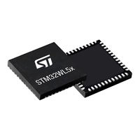
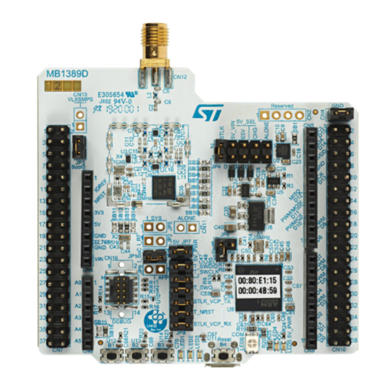
Manuals and User Guides for ST STM32WL5 Series. We have
2
ST STM32WL5 Series manuals available for free PDF download: Reference Manual
ST STM32WL5 Series Reference Manual (1461 pages)
Advanced Arm-based 32-bit MCUs with sub-GHz radio solution
Brand:
ST
| Category:
Microcontrollers
| Size: 17 MB
Table of Contents
Sub-Ghz Radio Generic Synchronization Word Control Register
1
Table of Contents
2
Sub-Ghz Radio Generic Synchronization Word Control Register
2
SYSCFG External Interrupt Configuration Register
3
Documentation Conventions
58
General Information
58
List of Abbreviations for Registers
58
Glossary
59
Availability of Peripherals
59
Memory and Bus Architecture
60
System Architecture
60
S0: CPU1 I-Bus
61
S1: CPU1 D-Bus
61
S2: CPU1 S-Bus
61
S3: CPU2 S-Bus
61
Figure 1. System Architecture
61
S4, S5: DMA-Bus
62
Boot Configuration
62
Table 1. Device Boot Mode
62
CPU2 Boot
64
SRAM Erase
65
Memory Protection
65
Table 2. SRAM Erase Conditions
65
Figure 2. Memory Protection Example
67
Table 3. Memory Security and Privilege Access
68
Memory Organization
70
Introduction
70
Memory Map and Register Boundary Addresses
71
Figure 3. Memory Map
71
Table 4. Memory Map and Peripheral Register Boundary Addresses
72
CPU1 Bit Banding
75
Global Security Controller (GTZC)
77
GTZC Introduction
77
GTZC Main Features
77
GTZC Security System Architecture
77
GTZC Functional Description
78
GTZC Block Diagram
78
Figure 4. GTZC Security Architecture
78
GTZC Internal Signals
79
Illegal Access Definition
79
Table 5. GTZC Internal Signals
79
Figure 5. GTZC Block Diagram
79
Table 6. Memory Access Error Generation
81
Security Controller (TZSC)
82
Table 7. Peripheral Access Error Generation
82
Security Illegal Access Controller (TZIC)
83
Power-On/Reset State
83
Figure 6. Memory Protection Control Water Mark
83
Interrupts
84
GTZC TZSC Registers
84
GTZC TZSC Control Register (GTZC_TZSC_CR)
84
Table 8. TZSC Privileged Mpcwmn Register Memory Allocation
84
GTZC TZSC Security Configuration Register (GTZC_TZSC_SECCFGR1)
85
GTZC TZSC Privileged Configuration Register (GTZC_TZSC_PRIVCFGR1)
86
GTZC TZSC Unprivileged Watermark 1 Register (GTZC_TZSC_MPCWM1_UPWMR)
87
GTZC TZSC Unprivileged Writable Watermark 1 Register (GTZC_TZSC_MPCWM1_UPWWMR)
88
GTZC TZSC Unprivileged Watermark 2 Register (GTZC_TZSC_MPCWM2_UPWMR)
89
GTZC TZSC Unprivileged Watermark 3 Register (GTZC_TZSC_MPCWM3_UPWMR)
90
GTZC TZSC Register Map
91
Table 9. GTZC TZSC Register Map and Reset Values
91
GTZC TZIC Registers
92
GTZC TZIC Interrupt Enable Register 1 (GTZC_TZIC_IER1)
92
GTZC TZIC Status Register 1 (GTZC_TZIC_MISR1)
93
GTZC TZIC Interrupt Status Clear Register 1 (GTZC_TZIC_ICR1)
95
GTZC TZIC Register Map
96
Table 10. TZIC Register Map and Reset Values
96
Embedded Flash Memory (FLASH)
97
FLASH Introduction
97
FLASH Main Features
97
FLASH Functional Description
97
Flash Memory Organization
97
Empty Check
98
Table 11. Flash Memory - Single Bank Organization
98
Error Code Correction (ECC)
99
Read Access Latency
99
Table 12. Number of Wait States According to Flash Clock (HCLK3) Frequency
99
Adaptive Real-Time Memory Accelerator (ART Accelerator)
100
Figure 7. Sequential 16 Bits Instructions Execution
102
Flash Program and Erase Operations
104
Flash Main Memory Erase Sequences
105
Table 13. Page Erase Overview
105
Table 14. Mass Erase Overview
106
Flash Main Memory Programming Sequences
107
Table 15. Errors in Page-Based Row Programming
111
FLASH Option Bytes
112
Option Bytes Description
112
Table 16. Option Bytes Organization
112
Option Bytes Programming
113
Table 17. Option Loading Control
115
Sub-Ghz Radio SPI Security
116
Secure System Memory
116
Introduction
116
RSSLIB Functions
116
Flash Memory Protection
117
Readout Protection (RDP)
117
Table 18. Flash Memory Readout Protection Status
117
Table 19. RDP Regression from Level 1 to Level 0 and Memory Erase
119
Table 20. Access Status Versus Protection Level and Execution Modes
120
Figure 8. Changing the RDP Level
120
Proprietary Code Readout Protection (PCROP)
121
Write Protection (WRP)
122
CPU2 Security (ESE)
123
Hide Protection Area (HDPAD)
125
CPU1 Boot Lock Chain of Trust
125
CPU2 Boot Lock Chain of Trust
125
FLASH Program Erase Suspension
125
FLASH Interrupts
126
Illegal Access Interrupts
126
Table 23. Flash Interrupt Requests
126
Register Access Protection
127
FLASH Registers
128
FLASH Access Control Register (FLASH_ACR)
128
FLASH Access Control Register 2 (FLASH_ACR2)
129
FLASH Key Register (FLASH_KEYR)
130
FLASH Option Key Register (FLASH_OPTKEYR)
130
FLASH Status Register (FLASH_SR)
131
FLASH Control Register (FLASH_CR)
133
FLASH ECC Register (FLASH_ECCR)
135
FLASH Option Register (FLASH_OPTR)
136
FLASH PCROP Zone a Start Address Register (FLASH_PCROP1ASR)
139
FLASH PCROP Zone a End Address Register
139
(Flash_Pcrop1Aer)
139
FLASH PCROP Zone a End Address Register (FLASH_PCROP1AER)
139
FLASH WRP Area a Address Register (FLASH_WRP1AR)
140
FLASH WRP Area B Address Register (FLASH_WRP1BR)
141
FLASH PCROP Zone B Start Address Register
142
(Flash_Pcrop1Bsr)
142
FLASH PCROP Zone B End Address Register
142
(Flash_Pcrop1Ber)
142
FLASH PCROP Zone B Start Address Register (FLASH_PCROP1BSR)
142
FLASH PCROP Zone B End Address Register (FLASH_PCROP1BER)
142
FLASH IPCC Mailbox Data Buffer Address Register
143
(Flash_Ipccbr)
143
FLASH IPCC Mailbox Data Buffer Address Register (FLASH_IPCCBR)
143
FLASH CPU2 Access Control Register (FLASH_C2ACR)
144
FLASH CPU2 Status Register (FLASH_C2SR)
144
FLASH CPU2 Control Register (FLASH_C2CR)
146
FLASH Secure Flash Start Address Register (FLASH_SFR)
148
FLASH Secure SRAM Start Address and CPU2 Reset Vector Register
149
(Flash_Srrvr)
149
FLASH Register Map
152
Table 25. Flash Interface Register Map and Reset Values
152
Sub-Ghz Radio (SUBGHZ)
154
Sub-Ghz Radio Introduction
154
Sub-Ghz Radio Main Features
154
Sub-Ghz Radio Functional Description
155
General Description
155
Sub-Ghz Radio Signals
155
Table 26. Sub-Ghz Internal Input/Output Signals
155
Figure 9. Sub-Ghz Radio System Block Diagram
155
Transmitter
156
Figure 10. High Output Power PA
156
Receiver
157
Table 27. Sub-Ghz Radio Transmit High Output Power
157
Figure 11. Low Output Power PA
157
Rf-Pll
158
Intermediate Frequencies
158
Table 28. FSK Mode Intermediate Frequencies
158
Sub-Ghz Radio Clocks
159
Internal Oscillators
159
HSE32 Reference Clock
159
Table 29. Lora Mode Intermediate Frequencies
159
Sub-Ghz Radio Modems
160
Lora Modem
160
Table 30. Spreading Factor, Chips/Symbol and Lora SNR
161
Table 31. Lora Bandwidth Setting
161
Lora Framing
162
Table 32. Coding Rate and Overhead Ratio
162
Figure 12. Lora Packet Frames Format
163
FSK Modem
164
MSK Modem
165
Generic Framing
165
Figure 13. Generic Packet Frames Format
166
BPSK Modem
167
BPSK Framing
167
Sub-Ghz Radio Data Buffer
168
Figure 14. Sub-Ghz RAM Data Buffer Operation
168
Receive Data Buffer Operation
169
Transmit Data Buffer Operation
169
Sub-Ghz Radio Operating Modes
169
Figure 15. Sub-Ghz Radio Operating Modes
170
Calibration Mode
171
Sleep Mode
171
Startup Mode
171
Frequency Synthesis Mode (FS)
172
Standby Mode
172
Transmit Mode (TX)
172
Active Mode Switching Time
173
Receive Mode (RX)
173
Sub-Ghz Radio SPI Interface
174
Figure 16. Sub-Ghz Radio BUSY Timing
174
Table 33. Operation Mode Transition BUSY Switching Time
174
Register and Buffer Access Commands
175
Sub-Ghz Radio Command Structure
175
Table 34. Command Structure
175
Operating Mode Commands
177
Figure 17. Receiver Listening Mode Timing
180
Sub-Ghz Radio Configuration Commands
182
Table 35. PA Optimal Setting and Operating Modes
185
Table 36. Recommended CAD Configuration Settings
187
Communication Status Information Commands
194
IRQ Interrupt Commands
197
Table 37. IRQ Bit Mapping and Definition
198
Miscellaneous Commands
199
Table 38. Image Calibration for ISM Bands
200
Set_Tcxomode Command
202
Table 39. Command Format Set_Tcxomode()
202
Sub-Ghz Radio Commands Overview
203
Table 40. Regtcxotrim and Timeout Bytes Definition
203
Table 41. Sub-Ghz Radio SPI Commands Overview
203
Sub-Ghz Radio Application Configuration
205
Basic Sequence for Lora, (G)MSK and (G)FSK Transmit Operation
205
Basic Sequence for Lora and (G)FSK Receive Operation
206
Basic Sequence for BPSK Transmit Operation
207
Sub-Ghz Radio Registers
207
Sub-Ghz Radio Generic Bit Synchronization Register (SUBGHZ_GBSYNCR)
207
Sub-Ghz Radio Generic Packet Control 1A Register (SUBGHZ_GPKTCTL1AR)
208
Sub-Ghz Radio Generic Whitening LSB Register (SUBGHZ_GWHITEINIRL)
208
Sub-Ghz Radio Generic CRC Initial MSB Register
209
Sub-Ghz Radio Generic CRC Initial LSB Register
209
Sub-Ghz Radio Generic CRC Polynomial MSB Register
209
Sub-Ghz Radio Generic CRC Polynomial LSB Register
210
Sub-Ghz Radio Generic Synchronization Word Control Register 7
210
(Subghz_Gsyncr7)
210
Sub-Ghz Radio Generic Synchronization Word Control Register 6
210
(Subghz_Gsyncr5)
210
Sub-Ghz Radio Generic Synchronization Word Control Register 3
211
(Subghz_Gsyncr4)
211
(Subghz_Gsyncr3)
211
(Subghz_Gsyncr2)
211
(Subghz_Gsyncr1)
211
Sub-Ghz Radio Generic Synchronization Word Control Register 0
212
(Subghz_Gsyncr0)
212
Sub-Ghz Radio Lora Synchronization Word MSB Register
212
(Subghz_Lsyncrh)
212
Sub-Ghz Radio Lora Synchronization Word LSB Register
212
(Subghz_Lsyncrl)
212
Sub-Ghz Radio Random Number Register 3 (SUBGHZ_RNGR3)
213
Sub-Ghz Radio Random Number Register 2 (SUBGHZ_RNGR2)
213
Sub-Ghz Radio Random Number Register 1 (SUBGHZ_RNGR1)
213
Sub-Ghz Radio Random Number Register 0 (SUBGHZ_RNGR0)
213
Sub-Ghz Radio Receiver Gain Control Register (SUBGHZ_RXGAINCR)
214
Sub-Ghz Radio PA over Current Protection Register
214
(Subghz_Paocpr)
214
Sub-Ghz Radio HSE32 OSC_IN Capacitor Trim Register
214
(Subghz_Hseintrimr)
214
Sub-Ghz Radio HSE32 OSC_OUT Capacitor Trim Register
215
(Subghz_Hseouttrimr)
215
Sub-Ghz Radio SMPS Control 0 Register (SUBGHZ_SMPSC0R)
215
Sub-Ghz Radio Power Control Register (SUBGHZ_PCR)
216
Sub-Ghz Radio SMPS Control 2 Register (SUBGHZ_SMPSC2R)
216
Sub-Ghz Radio Register Map
217
Table 42. SUBGHZ Radio Register Map and Reset Values
217
Power Control (PWR)
219
Power Supplies
219
Figure 18. Power Supply Overview
220
Figure 19. Supply Configurations
221
Independent Analog Peripherals Supply
222
Battery Backup Domain
223
Dynamic Voltage Scaling Management
224
Voltage Regulator
224
Power Supply Supervisor
225
Power-On Reset (Por)/Power-Down Reset (PDR)
225
Brownout Reset (BOR)
225
Programmable Voltage Detector (PVD)
226
Figure 20. Brownout Reset Waveform
226
Peripheral Voltage Monitoring (PVM)
227
Table 43. PVM Features
227
Figure 21. PVD Thresholds
227
Radio End of Life (EOL)
228
Radio Busy Management
228
Figure 22. EOL Thresholds
228
Figure 23. Radio Busy Management
229
CPU2 Boot
230
Figure 24. CPU2 Boot Options
231
Low-Power Modes
232
Figure 25. Cpus Low-Power Modes Possible Transitions
235
Table 44. Low-Power Mode Summary
236
Table 45. Functionalities Depending on System Operating Mode
237
Table 46. MCU and Sub-Ghz Radio Operating Modes
239
Low-Power Run Mode (Lprun)
240
Run Mode
240
Enter Low-Power Mode
241
Exit Low-Power Mode
241
Table 47. Lprun
241
Sleep Mode
243
Table 48. CPU Wakeup Versus System Operating Mode
243
Low-Power Sleep Mode (Lpsleep)
244
Table 49. Sleep Mode
244
Stop 0 Mode
245
Table 50. Lpsleep
245
Stop 1 Mode
247
Table 51. Stop 0 Mode
247
Stop 2 Mode
248
Table 52. Stop 1 Mode
248
Standby Mode
250
Table 53. Stop 2 Mode
250
Shutdown Mode
252
Table 54. Standby Mode
252
Auto-Wakeup from Low-Power Mode
253
Table 55. Shutdown Mode
253
PWR Registers
254
PWR Control Register 1 (PWR_CR1)
254
PWR Control Register 2 (PWR_CR2)
256
PWR Control Register 3 (PWR_CR3)
257
PWR Control Register 4 (PWR_CR4)
259
PWR Status Register 1 (PWR_SR1)
260
Power Status Register 2 (PWR_SR2)
261
PWR Status Clear Register (PWR_SCR)
263
PWR Control Register 5 (PWR_CR5)
264
PWR Port a Pull-Up Control Register (PWR_PUCRA)
265
PWR Port a Pull-Down Control Register (PWR_PDCRA)
265
PWR Port B Pull-Up Control Register (PWR_PUCRB)
266
PWR Port B Pull-Down Control Register (PWR_PDCRB)
266
PWR Port C Pull-Up Control Register (PWR_PUCRC)
267
PWR Port C Pull-Down Control Register (PWR_PDCRC)
267
PWR Port H Pull-Up Control Register (PWR_PUCRH)
268
PWR Port H Pull-Down Control Register (PWR_PDCRH)
268
PWR CPU2 Control Register 1 (PWR_C2CR1)
269
PWR CPU2 Control Register 3 (PWR_C2CR3)
270
PWR Extended Status and Status Clear Register (PWR_EXTSCR)
271
PWR Security Configuration Register (PWR_SECCFGR)
273
PWR Sub-Ghz SPI Control Register (PWR_SUBGHZSPICR)
273
PWR RSS Command Register (PWR_RSSCMDR)
274
PWR Register Map
275
Table 56. PWR Register Map and Reset Values
275
Reset and Clock Control (RCC)
277
Reset
277
Power Reset
277
System Reset
277
Figure 26. Simplified Diagram of the Reset Circuit
278
Backup Domain Reset
279
Sub-Ghz Radio Reset
279
PKA SRAM Reset
279
Clocks
279
HSE32 Clock with Trimming
282
Figure 27. Clock Tree
282
Figure 28. HSE32 Clock Sources
283
Figure 29. HSE32 TCXO Control
284
HSI16 Clock
285
MSI Clock
285
Pll
286
LSE Clock
287
Figure 30. LSE Clock Sources
287
LSI Clock
288
Clock Source Stabilization Time
288
System Clock (SYSCLK) Selection
288
Table 57. Clock Source Stabilization Times
288
Clock Source Frequency Versus Voltage Scaling
289
Clock Security System on HSE32 (CSS)
289
Table 58. Clock Source Frequency
289
Clock Security System on LSE (LSECSS)
290
SPI2S2 Clock
290
Table 59. SPI2S2 I2S Clock PLL Configurations
290
Sub-Ghz Radio SPI Clock
291
ADC Clock
291
RTC Clock
291
Timer Clock
291
Table 60. Sub-Ghz Radio SPI Clock Configurations
291
Watchdog Clock
292
True RNG Clock
292
Clock-Out Capability
292
Internal/External Clock Measurement with TIM16/TIM17
293
Figure 31. Frequency Measurement with TIM16 in Capture Mode
293
Figure 32. Frequency Measurement with TIM17 in Capture Mode
293
Peripheral Clocks Enable
295
Table 61. Peripheral Clock Enable
295
Low-Power Modes
296
Table 62. Low-Power Debug Configurations
296
RCC Registers
298
RCC Clock Control Register (RCC_CR)
298
RCC Internal Clock Sources Calibration Register (RCC_ICSCR)
301
RCC Clock Configuration Register (RCC_CFGR)
302
RCC PLL Configuration Register (RCC_PLLCFGR)
305
RCC Clock Interrupt Enable Register (RCC_CIER)
308
RCC Clock Interrupt Flag Register (RCC_CIFR)
309
RCC Clock Interrupt Clear Register (RCC_CICR)
310
RCC AHB1 Peripheral Reset Register (RCC_AHB1RSTR)
312
RCC AHB2 Peripheral Reset Register (RCC_AHB2RSTR)
312
RCC AHB3 Peripheral Reset Register (RCC_AHB3RSTR)
313
RCC APB1 Peripheral Reset Register 1 (RCC_APB1RSTR1)
314
RCC APB1 Peripheral Reset Register 2 (RCC_APB1RSTR2)
315
RCC APB2 Peripheral Reset Register (RCC_APB2RSTR)
316
RCC APB3 Peripheral Reset Register (RCC_APB3RSTR)
317
RCC AHB1 Peripheral Clock Enable Register (RCC_AHB1ENR)
318
RCC AHB2 Peripheral Clock Enable Register (RCC_AHB2ENR)
319
RCC AHB3 Peripheral Clock Enable Register (RCC_AHB3ENR)
320
RCC APB1 Peripheral Clock Enable Register 1 (RCC_APB1ENR1)
321
RCC APB1 Peripheral Clock Enable Register 2 (RCC_APB1ENR2)
322
RCC APB2 Peripheral Clock Enable Register (RCC_APB2ENR)
323
RCC APB3 Peripheral Clock Enable Register (RCC_APB3ENR)
324
RCC AHB1 Peripheral Clock Enable in Sleep Mode Register (RCC_AHB1SMENR)
325
RCC AHB2 Peripheral Clock Enable in Sleep Mode Register (RCC_AHB2SMENR)
326
RCC AHB3 Peripheral Clock Enable in Sleep and Stop Mode Register (RCC_AHB3SMENR)
327
RCC APB1 Peripheral Clock Enable in Sleep Mode Register 1
328
(Rcc_Apb1Smenr1)
328
RCC APB1 Peripheral Clock Enable in Sleep Mode Register 2
330
(Rcc_Apb1Smenr2)
330
RCC APB2 Peripheral Clock Enable in Sleep Mode Register (RCC_APB2SMENR)
331
RCC APB3 Peripheral Clock Enable in Sleep Mode Register (RCC_APB3SMENR)
332
RCC Peripherals Independent Clock Configuration Register
333
(Rcc_Ccipr)
333
RCC Backup Domain Control Register (RCC_BDCR)
335
RCC Control/Status Register (RCC_CSR)
337
RCC Extended Clock Recovery Register (RCC_EXTCFGR)
340
RCC CPU2 AHB1 Peripheral Clock Enable Register (RCC_C2AHB1ENR)
342
RCC CPU2 AHB2 Peripheral Clock Enable Register (RCC_C2AHB2ENR)
343
RCC CPU2 AHB3 Peripheral Clock Enable Register (RCC_C2AHB3ENR)
344
RCC CPU2 APB1 Peripheral Clock Enable Register 1
345
(Rcc_C2Apb1Enr1)
345
RCC CPU2 APB1 Peripheral Clock Enable Register 2
346
(Rcc_C2Apb1Enr2)
346
RCC CPU2 APB2 Peripheral Clock Enable Register (RCC_C2APB2ENR)
347
RCC CPU2 APB3 Peripheral Clock Enable Register (RCC_C2APB3ENR)
348
RCC CPU2 AHB1 Peripheral Clock Enable in Sleep Mode Register (RCC_C2AHB1SMENR)
349
RCC CPU2 AHB2 Peripheral Clock Enable in Sleep Mode Register (RCC_C2AHB2SMENR)
350
RCC CPU2 AHB3 Peripheral Clock Enable in Sleep Mode Register (RCC_C2AHB3SMENR)
351
RCC CPU2 APB1 Peripheral Clock Enable in Sleep Mode Register 1
352
(Rcc_C2Apb1Smenr1)
352
RCC CPU2 APB1 Peripheral Clock Enable in Sleep Mode Register 2
354
(Rcc_C2Apb1Smenr2)
354
RCC CPU2 APB2 Peripheral Clock Enable in Sleep Mode Register (RCC_C2APB2SMENR)
355
RCC CPU2 APB3 Peripheral Clock Enable in Sleep Mode Register (RCC_C2APB3SMENR)
356
RCC Register Map
357
Table 63. RCC Register Map and Reset Values
357
Hardware Semaphore (HSEM)
365
Introduction
365
Main Features
365
Functional Description
366
HSEM Block Diagram
366
HSEM Internal Signals
366
HSEM Lock Procedures
366
Table 64. HSEM Internal Input/Output Signals
366
Figure 33. HSEM Block Diagram
366
Figure 34. Procedure State Diagram
367
HSEM Write/Read/Read Lock Register Address
368
HSEM Unlock Procedures
368
HSEM COREID Semaphore Clear
369
HSEM Interrupts
369
Figure 35. Interrupt State Diagram
370
AHB Bus Master ID Verification
371
Table 65. Authorized AHB Bus Master Ids
371
HSEM Registers
372
HSEM Register Semaphore X (Hsem_Rx)
372
HSEM Read Lock Register Semaphore X (Hsem_Rlrx)
373
HSEM Interrupt Enable Register (Hsem_Cnier)
374
HSEM Interrupt Clear Register (Hsem_Cnicr)
374
HSEM Interrupt Status Register (Hsem_Cnisr)
374
HSEM Interrupt Status Register (Hsem_Cnmisr)
375
HSEM Clear Register (HSEM_CR)
375
HSEM Interrupt Clear Register (HSEM_KEYR)
376
HSEM Register Map
377
Table 66. HSEM Register Map and Reset Values
377
Inter-Processor Communication Controller (IPCC)
379
IPCC Introduction
379
IPCC Main Features
379
IPCC Functional Description
379
IPCC Block Diagram
380
IPCC Simplex Channel Mode
380
Table 67. IPCC Interface Signals
380
Figure 36. IPCC Block Diagram
380
Table 68. Bits Used for the Communication
381
Figure 37. IPCC Simplex Channel Mode Transfer Timing
381
Figure 38. IPCC Simplex - Send Procedure State Diagram
382
IPCC Half-Duplex Channel Mode
383
Figure 39. IPCC Simplex - Receive Procedure State Diagram
383
Figure 40. IPCC Half-Duplex Channel Mode Transfer Timing
384
Figure 41. IPCC Half-Duplex - Send Procedure State Diagram
384
Figure 42. IPCC Half-Duplex - Receive Procedure State Diagram
385
IPCC Interrupts
386
IPCC Registers
386
IPCC Processor 1 Control Register (IPCC_C1CR)
386
IPCC Processor 1 Mask Register (IPCC_C1MR)
387
IPCC Processor 1 Status Set Clear Register (IPCC_C1SCR)
388
IPCC Processor 1 to Processor 2 Status Register (IPCC_C1TOC2SR)
388
IPCC Processor 2 Control Register (IPCC_C2CR)
389
IPCC Processor 2 Mask Register (IPCC_C2MR)
389
IPCC Processor 2 Status Set Clear Register (IPCC_C2SCR)
390
IPCC Processor 2 to Processor 1 Status Register (IPCC_C2TOC1SR)
391
IPCC Register Map
392
Table 69. IPCC Register Map and Reset Values
392
General-Purpose I/Os (GPIO)
393
GPIO Introduction
393
GPIO Main Features
393
GPIO Functional Description
393
Figure 43. Basic Structure of a Standard I/O Port Bit
394
Figure 44. Basic Structure of a 5V-Tolerant I/O Port Bit
395
Table 70. Port Bit Configurations
395
General Purpose I/O (GPIO)
396
I/O Pin Alternate Function Multiplexer and Mapping
396
I/O Data Bitwise Handling
397
I/O Port Control Registers
397
I/O Port Data Registers
397
External Interrupt/Wakeup Lines
398
GPIO Locking Mechanism
398
I/O Alternate Function Input/Output
398
Figure 45. Input Floating/Pull-Up/Pull-Down Configurations
399
Input Configuration
399
Output Configuration
399
Alternate Function Configuration
400
Figure 46. Output Configuration
400
Figure 47. Alternate Function Configuration
400
Analog Configuration
401
Figure 48. High Impedance Analog Configuration
401
Using the GPIO Pins in the RTC Supply Domain
401
Using the LSE Oscillator Pins as Gpios
401
Using PH3 as GPIO
402
GPIO Registers
402
Gpiox Mode Register (Gpiox_Moder) (X = a to B)
402
Gpiox Output Type Register (Gpiox_Otyper) (X = a to B)
403
Gpiox Output Speed Register (Gpiox_Ospeedr) (X = a to B)
403
Gpiox Pull-Up/Pull-Down Register (Gpiox_Pupdr) (X = a to B)
404
Gpiox Input Data Register (Gpiox_Idr) (X = a to B)
405
Gpiox Output Data Register (Gpiox_Odr) (X = a to B)
406
Gpiox Bit Set/Reset Register (Gpiox_Bsrr) (X = a to B)
406
Gpiox Configuration Lock Register (Gpiox_Lckr) (X = a to B)
407
Gpiox Alternate Function Low Register (Gpiox_Afrl) (X = a to B)
408
Gpiox Alternate Function High Register (Gpiox_Afrh) (X = a to B)
408
Gpiox Bit Reset Register (Gpiox_Brr) (X = a to B)
409
GPIOC Mode Register (GPIOC_MODER)
409
GPIOC Output Type Register (GPIOC_OTYPER)
410
GPIOC Output Speed Register (GPIOC_OSPEEDR)
411
GPIOC Pull-Up/Pull-Down Register (GPIOC_PUPDR)
412
GPIOC Input Data Register (GPIOC_IDR)
412
GPIOC Output Data Register (GPIOC_ODR)
413
GPIOC Bit Set/Reset Register (GPIOC_BSRR)
414
GPIOC Configuration Lock Register (GPIOC_LCKR)
415
GPIOC Alternate Function Low Register (GPIOC_AFRL)
416
GPIOC Alternate Function High Register (GPIOC_AFRH)
417
GPIOC Bit Reset Register (GPIOC_BRR)
417
GPIOH Mode Register (GPIOH_MODER)
418
GPIO H Output Type Register (GPIOH_OTYPER)
418
GPIOH Output Speed Register (GPIOH_OSPEEDR)
419
GPIOH Pull-Up/Pull-Down Register (GPIOH_PUPDR)
419
GPIOH Input Data Register (GPIOH_IDR)
420
GPIOH Output Data Register (GPIOH_ODR)
420
GPIO H Bit Set/Reset Register (GPIOH_BSRR)
421
GPIOH Configuration Lock Register (GPIOH_LCKR)
421
GPIOH Alternate Function Low Register (GPIOH_AFRL)
422
GPIOH Bit Reset Register (GPIOH_BRR)
423
GPIOA Register Map
423
Table 71. GPIOA Register Map and Reset Values
423
GPIOB Register Map
424
Table 72. GPIOB Register Map and Reset Values
424
GPIOC Register Map
425
Table 73. GPIOC Register Map and Reset Values
425
GPIOH Register Map
426
Table 74. GPIOH Register Map and Reset Values
426
System Configuration Controller (SYSCFG)
428
SYSCFG Main Features
428
SYSCFG Registers
428
SYSCFG Memory Remap Register (SYSCFG_MEMRMP)
428
SYSCFG Configuration Register 1 (SYSCFG_CFGR1)
429
SYSCFG External Interrupt Configuration Register 1
430
(Syscfg_Exticr1)
430
SYSCFG External Interrupt Configuration Register 2
431
(Syscfg_Exticr2)
431
(Syscfg_Exticr3)
432
SYSCFG External Interrupt Configuration Register 4
434
(Syscfg_Exticr4)
434
SYSCFG SRAM Control and Status Register (SYSCFG_SCSR)
435
SYSCFG Configuration Register 2 (SYSCFG_CFGR2)
436
SYSCFG SRAM2 Write Protection Register (SYSCFG_SWPR)
437
SYSCFG SRAM2 Key Register (SYSCFG_SKR)
438
SYSCFG CPU1 Interrupt Mask Register 1 (SYSCFG_IMR1)
439
SYSCFG CPU1 Interrupt Mask Register 2 (SYSCFG_IMR2)
440
SYSCFG CPU2 Interrupt Mask Register 1 (SYSCFG_C2IMR1)
440
SYSCFG CPU2 Interrupt Mask Register 2 (SYSCFG_C2IMR2)
442
SYSCFG Radio Debug Control Register (SYSCFG_RFDCR)
443
SYSCFG Register Map
444
Table 75. SYSCFG Register Map and Reset Values
444
Peripherals Interconnect Matrix
446
Introduction
446
Connection Summary
446
Table 76. Stm32Wl5X Peripherals Interconnect Matrix
446
Interconnection Details
447
From Timer (TIM1/TIM2/TIM17) to Timer (TIM1/TIM2)
447
From Timer (LPTIM1/LPTIM2) to Timer (LPTIM3)
448
From Timer (TIM1/TIM2) and GPIO Pin EXTI to ADC/DAC
448
From Timer (LPTIM1/LPTIM2) to DAC
449
From ADC to Timer (TIM1)
449
From HSE32, LSE, LSI, MSI, MCO, RTC to Timers (TIM2/TIM16/TIM17)
449
(Lptim1/Lptim2)
450
From Timer (TIM1/TIM2) to Comparators (COMP1/COMP2)
450
From Internal Analog to ADC
451
From Comparators (COMP1/COMP2) to Timers
451
(Tim1/Tim2/Tim16/Tim17)
451
From System Errors to Timers (TIM1/TIM16/TIM17)
452
From Timers (TIM16/TIM17) to IRTIM
452
From Timer (LPTIM1/LPTIM2/LPTIM3/GPIO Pin EXTI)
452
To DMAMUX1 Trigger
452
From Timer (LPTIM3) to Sub-Ghz Radio SPI NSS
453
Direct Memory Access Controller (DMA)
454
Introduction
454
DMA Main Features
454
DMA Implementation
455
DMA1 and DMA2
455
DMA Request Mapping
455
Table 77. DMA1 and DMA2 Implementation
455
DMA Functional Description
456
DMA Block Diagram
456
Figure 49. DMA Block Diagram
456
DMA Pins and Internal Signals
457
DMA Transfers
457
Table 78. DMA Internal Input/Output Signals
457
DMA Arbitration
458
DMA Channels
459
DMA Data Width, Alignment and Endianness
464
Table 79. Programmable Data Width and Endian Behavior (When PINC = MINC = 1)
464
DMA Error Management
465
DMA Interrupts
466
DMA Registers
466
DMA Interrupt Status Register (DMA_ISR)
466
Table 80. DMA Interrupt Requests
466
DMA Interrupt Flag Clear Register (DMA
469
DMA Channel X Configuration Register (Dma_Ccrx)
470
DMA Channel X Number of Data to Transfer Register (Dma_Cndtrx)
475
DMA Channel X Peripheral Address Register (Dma_Cparx)
476
DMA Channel X Memory Address Register (Dma_Cmarx)
476
DMA Register Map
477
Table 81. DMA Register Map and Reset Values
477
Advertisement
ST STM32WL5 Series Reference Manual (1454 pages)
Advanced Arm-based 32-bit MCUs with sub-GHz radio solution
Brand:
ST
| Category:
Microcontrollers
| Size: 29 MB
Table of Contents
Table of Contents
2
List of Tables
46
Documentation Conventions
60
General Information
60
List of Abbreviations for Registers
60
Availability of Peripherals
61
Glossary
61
Memory and Bus Architecture
62
System Architecture
62
Figure 1. System Architecture
63
S0: CPU1 I-Bus
63
S1: CPU1 D-Bus
63
S2: CPU1 S-Bus
63
S3: CPU2 S-Bus
63
Boot Configuration
64
S4, S5: DMA-Bus
64
Table 1. Device Boot Mode
64
CPU2 Boot
66
Memory Protection
67
SRAM Erase
67
Table 2. SRAM Erase Conditions
67
Figure 2. Memory Protection Example
69
Table 3. Memory Security and Privilege Access
70
Introduction
72
Memory Organization
72
Figure 3. Memory Map
73
Memory Map and Register Boundary Addresses
73
Table 4. Memory Map and Peripheral Register Boundary Addresses
74
CPU1 Bit Banding
77
Global Security Controller (GTZC)
79
GTZC Introduction
79
GTZC Main Features
79
GTZC Security System Architecture
79
Figure 4. GTZC Security Architecture
80
GTZC Block Diagram
80
GTZC Functional Description
80
Figure 5. GTZC Block Diagram
81
GTZC Internal Signals
81
Illegal Access Definition
81
Table 5. GTZC Internal Signals
81
Table 6. Memory Access Error Generation
83
Security Controller (TZSC)
84
Table 7. Peripheral Access Error Generation
84
Figure 6. Memory Protection Control Water Mark
85
Power-On/Reset State
85
Security Illegal Access Controller (TZIC)
85
GTZC TZSC Control Register (GTZC_TZSC_CR)
86
GTZC TZSC Registers
86
Interrupts
86
Table 8. TZSC Privileged Mpcwmn Register Memory Allocation
86
GTZC TZSC Security Configuration Register (GTZC_TZSC_SECCFGR1)
87
GTZC TZSC Privileged Configuration Register (GTZC_TZSC_PRIVCFGR1)
88
GTZC TZSC Unprivileged Watermark 1 Register (GTZC_TZSC_MPCWM1_UPWMR)
89
GTZC TZSC Unprivileged Writable Watermark 1 Register (GTZC_TZSC_MPCWM1_UPWWMR)
90
GTZC TZSC Unprivileged Watermark 2 Register (GTZC_TZSC_MPCWM2_UPWMR)
91
GTZC TZSC Unprivileged Watermark 3 Register (GTZC_TZSC_MPCWM3_UPWMR)
92
GTZC TZSC Register Map
93
Table 9. GTZC TZSC Register Map and Reset Values
93
GTZC TZIC Interrupt Enable Register 1 (GTZC_TZIC_IER1)
94
GTZC TZIC Registers
94
GTZC TZIC Status Register 1 (GTZC_TZIC_MISR1)
95
GTZC TZIC Interrupt Status Clear Register 1 (GTZC_TZIC_ICR1)
97
GTZC TZIC Register Map
98
Table 10. TZIC Register Map and Reset Values
98
Embedded Flash Memory (FLASH)
99
FLASH Functional Description
99
FLASH Introduction
99
FLASH Main Features
99
Flash Memory Organization
99
Empty Check
100
Table 11. Flash Memory - Single Bank Organization
100
Error Code Correction (ECC)
101
Read Access Latency
101
Table 12. Number of Wait States According to Flash Clock (HCLK3) Frequency
102
Adaptive Real-Time Memory Accelerator (ART Accelerator)
103
Figure 7. Sequential 16 Bits Instructions Execution
104
Flash Program and Erase Operations
106
Flash Main Memory Erase Sequences
107
Table 13. Page Erase Overview
107
Table 14. Mass Erase Overview
108
Flash Main Memory Programming Sequences
109
Table 15. Errors in Page-Based Row Programming
113
Advertisement
Related Products
ST STM32WL55JC
ST STM32WL54 Series
ST SimpleMAC STM32W108 Series
ST SimpleMAC STM32W108HB
ST SimpleMAC STM32W108CB
ST SimpleMAC STM32W108C8
ST SimpleMAC STM32W108CZ
ST SimpleMAC STM32W108CC
ST STM32WB55
st STM32F429 Series
ST Categories
Motherboard
Computer Hardware
Microcontrollers
Control Unit
Controller
More ST Manuals
Login
Sign In
OR
Sign in with Facebook
Sign in with Google
Upload manual
Upload from disk
Upload from URL