Keysight E4980A User Manual
Precision lcr meter
Hide thumbs
Also See for E4980A:
- Service manual (137 pages) ,
- Technical overview (28 pages) ,
- User manual (529 pages)
Table of Contents
Advertisement
Quick Links
Advertisement
Table of Contents

Subscribe to Our Youtube Channel
Related Manuals for Keysight E4980A


Summary of Contents for Keysight E4980A
- Page 1 Keysight E4980A/AL Precision LCR Meter User’s Guide...
- Page 2 EULA. governed by United States and Declaration of Conformity Keysight shall be under no obligation international copyright laws. to update, revise or otherwise modify Trademark Acknowledgments Declarations of Conformity for this the Software.
-
Page 3: Table Of Contents
Starting the E4980A/AL ........ - Page 4 MEAS SETUP page ............88 Keysight E4980A/AL User’s Guide...
- Page 5 To set the correction function to on or off ........113 The correction functions of the E4980A/AL are operated as follows:....114 Open Correction .
- Page 6 Parallel/Series Circuit Mode ..........190 Keysight E4980A/AL User’s Guide...
- Page 7 Trigger System ............245 Keysight E4980A/AL User’s Guide...
- Page 8 E4980A/AL commands ........
- Page 9 :CORRection:OPEN[:EXECute] ..........334 Keysight E4980A/AL User’s Guide...
- Page 10 :HCOPy:SDUMp:DATA ........... .351 Keysight E4980A/AL User’s Guide...
- Page 11 :SYSTem:COMMunicate:LAN[:SELF]:CURRent:ADDRess? ..... . . 368 :SYSTem:COMMunicate:LAN[:SELF]:CURRent:DGATeway? ..... . 368 Keysight E4980A/AL User’s Guide...
- Page 12 Recommended Calibration Period ......... .418 13. Troubleshooting Keysight E4980A/AL User’s Guide...
- Page 13 T ..............435 Keysight E4980A/AL User’s Guide...
- Page 14 Signals Activated when Overload Occurs ........482 Keysight E4980A/AL User’s Guide...
- Page 15 Correction Data Confirmation ..........507 G.Functional Comparison between 4284A, 4279A and E4980A/AL Functional Comparison between 4284A, 4279A, and E4980A/AL ....511 Keysight E4980A/AL User’s Guide...
- Page 16 Contents Keysight E4980A/AL User’s Guide...
-
Page 17: Unpacking And Preparation
Contents of this Chapter Checking the Shipment on page? After you receive the E4980A/AL, check all the items in the packing container. Preparation before Use on page? Shows how to check the power supply as well as check and connect the power cable. -
Page 18: Checking The Shipment
1-1, check that all packaged items supplied with the LCR meter have been provided as per the specified options. Step 4. After checking, if one of the following applies, contact your nearest Keysight Technologies sales and service office. 1. The packing box or shock-absorbing material used to package the LCR meter has been damaged or the shock-absorbing material displays traces of where extreme pressure has been applied. - Page 19 - E4980A/AL E4980A/AL 8120-4753 -Power Cable -USB Cable 82357-61601 -CD-ROM (of the manual and the sample program) See footnote -CD-ROM (of the Keysight IO Libraries suite) See footnote Options -Manual (Option ABA) • User’s Guide See footnote 5063-9241 -Rack mount kit without handles (Option 1CM) 1.
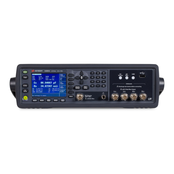
- Page 20 UNKNOWN DC Bias Display Meas Discharge test device before connecting Format Setup 42V Peak Max Output CAT I Source DC Source (Option 001) Return 10VDC Max Save/ Local/ Recall A Recall B System Recall Lock Keysight E4980A/AL Precision LCR Meter...
-
Page 21: Preparations Before Use
47 to 63 Hz Maximum power 150 VA consumption 1. Switched automatically by the E4980A/AL in conformity with the voltage used. Setting up the Fuse Please use the following fuse type. UL/CSA type, Slo-Blo, 520-mm miniature fuse, 3 A, 250 V (Keysight part... -
Page 22: Verifying And Connecting The Power Cable
Preparations before Use Verifying and Connecting the Power Cable The three-wire power cable attached to the E4980A/AL has one wire serving as a ground. Using this power cable allows the E4980A/AL to be grounded, thereby protecting you against electrical shock from the power outlet. - Page 23 Unpacking and Preparation Preparations before Use Figure 1-3 Power cable options Keysight E4980A/AL Precision LCR Meter...
-
Page 24: How To Remove The Handle
Unpacking and Preparation How to Remove the Handle How to Remove the Handle A handle kit is attached to the E4980A/AL. When using the E4980A/AL with the rack-mount kit, remove the handle according to the following steps. Figure 1-4 How to remove the handle Step 1. -
Page 25: Caution When Using The Handle
Caution when Using the Handle Caution when Using the Handle Follow the instructions below when using the E4980A/AL’s handle, otherwise you may get your fingers caught in the handle or the E4980A/AL may fall and be damaged • When the handle is set up as shown in... -
Page 26: Environmental Requirements
Unpacking and Preparation Environmental Requirements Environmental Requirements Set up the E4980A/AL where the following environmental requirements are satisfied. Operating Environments Ensure that the operating environment meets the following requirements. Table 1-3 Operating Environments Requirements Temperature 0ºC to 55ºC 23ºC 5ºC (<1ºC deviation from the temperature... -
Page 27: Ventilation Requirements
The LCR meter still conforms to the requirements of the safety standard it is installed with the following cooling clearance: Requirements Back 180 mm Sides 60 mm (both right and left) Figure 1-6 Ventilation space at installation Keysight E4980A/AL Precision LCR Meter... -
Page 28: Protection Against Electrostatic Discharge (Esd)
E4980A/AL. When installing the E4980A/AL, ensure that there is sufficient free space around the unit to permit quick disconnection of the plug (from the AC outlet or the E4980A/AL unit) in case of emergency. -
Page 29: Starting The E4980A/Al
Unpacking and Preparation Starting the E4980A/AL Starting the E4980A/AL This section describes how to turn on/off the E4980A/AL power and how to cut off the power supply in an emergency. Turning the Power ON and OFF Turning the Power ON... -
Page 30: Disconnecting From The Supply Source
(device that cuts off the power supply) of the E4980A/AL. When the power supply must be cut off to avoid such danger as electric shock, pull out the power cable’s plug (on the power outlet side or device side of the cable). -
Page 31: Overview
(0.1 mVrms to 2 Vrms, 50 A to 20 mArms). With Option 001, the E4980A/AL’s test signal level range spans 0.1 mV to 20 Vrms, and 50 A to 200 mArms. Also, the E4980A/AL with Option 001 enables up to 40-Vrms DC bias measurements (without Option 001, up to ... -
Page 32: Front Panel: Names And Functions Of Parts
Front Panel: Names and Functions of Parts This section describes the names and functions of the parts on the E4980A/AL’s front panel. For more details on the functions displayed on the LCD screen, see “Screen Area: Names and Functions of Parts” on page 40. -
Page 33: Power Switch
Front Panel: Names and Functions of Parts 1. Power switch Used for choosing between power-on and -off states of the E4980A/AL. When turned on, the switch lights up in yellow-green and all operating voltages are applied to the instrument. When turned off, the switch lights up in orange and no operating voltages are applied to the instrument. -
Page 34: Entry Keys
“Initializing the Instrument” on page 9. Trigger key A key used to manually trigger the E4980A/AL when it is set to the manual trigger mode. 10. DC Bias key A key used to toggle on and off of the DC bias output. When the DC bias output is set to on, the DC bias indicator lights up and DCBIAS is displayed in the status display area on the screen. -
Page 35: Unknown Terminals
LIST SWEEP DISPLAY page displayed, the value set in the DC SRC field is output when the DC SRC key is pressed. Then, after the E4980A/AL is triggered, the DC Source is set according to the list that has been set. -
Page 36: Ground Terminal
169. Interface: USB 1.1 14. Ground terminal Connected to the chassis of the E4980A/AL. This is used for measurements that require guarding. 15. DC Source terminal Outputs the DC source in the range from -10 V to 10 V. Option 001 is required for this function. -
Page 37: Rear Panel: Names And Functions Of Parts
2. Interface Connector If interface options are installed, the interface connectors will be installed as shown. If the E4980A/AL is not equipped with an interface option, blank panels will cover this portion. Interfaces with which the E4980A/AL can be equipped as options are shown below. -
Page 38: Usb (Usbtmc) Interface Port
Compliance Standards: USBTMC-USB488 and USB2.0 4. LAN Port The port to connect the E4980A/AL to a LAN (Local Area Network). Connecting this instrument to a LAN enables you to control this instrument by using SICL-LAN or telnet, or from an external PC via a Web server. -
Page 39: Power Cable Receptacle (To Line)
For more on the power supply, see “Verifying and Connecting the Power Cable” on page 8. Fan The cooling fan for controlling the temperature inside the E4980A/AL. This fan extracts heated air from inside the LCR meter. Keysight E4980A/AL Precision LCR Meter... -
Page 40: Screen Area: Names And Functions Of Parts
Overview Screen Area: Names and Functions of Parts Screen Area: Names and Functions of Parts This section describes the names and functions of parts on the E4980A/AL’s LCD screen. Figure 2-3 Screen display 1. Display Page Area Shows a display page name of the current display page. On each display page, three lines are collected together as one area. -
Page 41: Softkey Area
This means that no measurement has been made or the data format will not hold the measurement results. INFINITY This message is displayed when a deviation mode of the deviation measurement function is % and measurement results cannot be calculated. Keysight E4980A/AL Precision LCR Meter... -
Page 42: Input Line Area
Displays the status when DC bias or DC source is on, or any front panel key is locked. When sending SCPI commands from the external controller, “RMT” is displayed and the front panel keys are locked. Keysight E4980A/AL Precision LCR Meter... -
Page 43: Basic Operation
Overview Basic Operation Basic Operation The E4980A/AL’s basic operation is described below. 1. Display the desired page using both the MENU keys and softkeys. 2. Move the cursor to the desired field using the cursor keys. When the cursor is moved to a certain field, the field changes to an inverse video image of the original. -
Page 44: How To Use Skip Keys
On a display page, three lines are collected together as one. By using a skip key, you can select the desired field quickly as the selected field moves from area to area. Figure 2-6 Skip key and a field operation example Return Keysight E4980A/AL Precision LCR Meter... -
Page 45: Display Format
Keysight E4980A/AL Precision LCR Meter User’s Guide Display Format This chapter describes each page of the DISPLAY FORMAT MENU of the E4980A/AL. MEAS DISPLAY Page When you press the [DISPLAY FORMAT] key, the MEAS DISPLAY page appears. The following measurement controls can be set on this page (The field in parenthesis is used to set measurement controls). - Page 46 Figure 3-1 is displayed enlarges the measurement result as shown in Figure 3-2. Pressing the [DISPLAY FORMAT] key again returns to the display in Figure 3-1. Figure 3-2 The enlarged MEAS DISPLAY for measurement results Keysight E4980A/AL Precision LCR Meter...
-
Page 47: Measurement Function
1. This parameter can be set only when the E4980A/AL is equipped with either option 001, 030/032, 050/052, 100 or 200. 2. This parameter can be set only when the E4980A/AL is equipped with option 001. When the measurement parameter is DC voltage measurement/DC current measurement (Vdc-Idc), set the setting value of the test signal level (LEVEL field) to 0 V for accurate measurement. - Page 48 Inductance value measured using the series equivalent circuit model Resistance Absolute value of impedance Conductance Absolute value of admittance DC voltage 1. This parameter can be set only when the E4980A/AL is equipped with option 001. Table 3-3 Secondary parameter Parameter Description Dissipation factor...
- Page 49 Parameter Description DC resistance 1. This parameter can be set only when the E4980A/AL is equipped with option 001. 2. This parameter can be set only when the E4980A/AL is equipped with either option 001, 030/032, 050/052, 100 or 200.
- Page 50 Step 4. Use the softkeys to select the primary parameter. Step 5. If the secondary parameter exists, select the secondary parameter from measurement parameters displayed using the softkeys. For the combinations of measurement parameters, refer to Table 3-1 on page Keysight E4980A/AL Precision LCR Meter...
-
Page 51: Impedance Range
Option 001 100 m , 1, 10, 100, 300, 1 k, 3k, 10 k, 30 k, 100k 1. This cannot be used when the test signal level is less than or equal to 2 V. Keysight E4980A/AL Precision LCR Meter... - Page 52 (| Z |, R, X). For example, 50-k DUT impedance can be measured using the ranges of 100 k to 30 k, but the E4980A/AL’s accuracy specification is only met when using the 30-k range. If this DUT is measured with the 100-k range, “OVERLOAD”...
- Page 53 27.6 k. Effective measurement range for each impedance range The following shows the effective measurement range of each impedance range, in which the E4980A/AL’s measurement accuracy meets its specifications. When the impedance range is set manually, the optimum impedance range...
- Page 54 Display Format MEAS DISPLAY Page Figure 3-4 Effective measurement range (0.2V or 2 mA < Test signal level 2 V or 20 mA) Keysight E4980A/AL Precision LCR Meter...
- Page 55 Display Format MEAS DISPLAY Page Figure 3-5 Effective measurement range (Test signal level > 2 V or 20 mA) Keysight E4980A/AL Precision LCR Meter...
- Page 56 Display Format MEAS DISPLAY Page Figure 3-6 Effective measurement range (Test signal level 0.2 V or 2 mA) Keysight E4980A/AL Precision LCR Meter...
- Page 57 Manually setting the time for the impedance range mode Changing impedance range requires a few milliseconds to several tens of milliseconds. For details, refer to Settling Time in data sheet in Chapter 11 “Specifications and Supplemental Information” Keysight E4980A/AL Precision LCR Meter...
-
Page 58: Test Frequency
Test Frequency Test frequency point The E4980A/AL’s test frequency can be set in the range from 20 Hz to 2 MHz. The last digit of the four-digit test frequency display (including digits after the decimal point) can be set as the resolution. - Page 59 300 kHz 80 Hz 400 Hz 4 kHz 40 kHz 400 kHz 500 Hz 5 kHz 50 kHz 500 kHz 600 Hz 6 kHz 60 kHz 600 kHz 800 Hz 8 kHz 80 kHz 800 kHz Keysight E4980A/AL Precision LCR Meter...
- Page 60 Time required for setting the test frequency Changing the test frequency requires a few milliseconds to several tens of milliseconds. For details, refer to Settling Time in data sheet in Chapter 11 “Specifications and Supplemental Information” Keysight E4980A/AL Precision LCR Meter...
-
Page 61: Test Signal Level
MEAS DISPLAY Page Test Signal Level The E4980A/AL’s test signal level can be set as the effective value (RMS value) of a sine wave of the test frequency from the unit’s internal oscillator. You can set either the oscillator voltage level or the oscillator current level. The output impedance is 100 . - Page 62 50 mArms to 100 mArms 50 Arms Test signal level setting procedure Step 1. Press the [Display Format] key Step 2. Press the MEAS DISPLAY softkey. Step 3. Use the cursor keys to select the LEVEL field. Keysight E4980A/AL Precision LCR Meter...
- Page 63 1 m, 2 m, 3 m, •••, 9 m 10 m, 20 m, 30 m, •••, 90 m 100 m 1. The current level can be set to more than 20 m only when option 001 is installed. Keysight E4980A/AL Precision LCR Meter...
-
Page 64: Dc Bias
MEAS DISPLAY Page DC Bias The E4980A/AL has an internal DC bias. A DC bias is output when the DC Bias key on the front panel is set to ON. The DC Bias key is a toggle-type switch used to enable DC bias output. When you press the DC Bias key, DCBIAS appears in the status display area and the LED indicator for DC bias is ON (orange). - Page 65 Test signal level Vdc (V) Vosc (Vrms) Vosc 2 1.15 + Vdc 1.002 < 42 V Vdc (V) Iosc (Arms) Iosc 2 115 + Vdc 1.002 < 42 V Keysight E4980A/AL Precision LCR Meter...
- Page 66 1 m, 2 m, 3 m, •••, 9 m 10 m, 20 m, 30 m, •••, 90 m 100 m, 200 m, 300 m, •••, 900 m 1, 2, 3, •••, 9 10, 20, 30, 40 Keysight E4980A/AL Precision LCR Meter...
- Page 67 Settling time for the DC bias signal voltage Changing the DC bias requires a few milliseconds to several tens of milliseconds. For details, refer to DC bias settling time in data sheet in Chapter 11 “Specifications and Supplemental Information” Keysight E4980A/AL Precision LCR Meter...
-
Page 68: Measurement Time Mode
MEAS DISPLAY Page Measurement Time Mode Three measurement time modes (SHORT, MEDIUM, LONG) can be selected for the E4980A/AL. A longer measurement time will result in more stable and accurate measurement results. Refer to “Measurement time” on page 442 details on the measurement time of each measurement time mode. -
Page 69: Display Setting For Measurement Results
Display Format MEAS DISPLAY Page Display Setting for Measurement Results The E4980A/AL can set the display digits and display units for measurement results (primary parameter/secondary parameter). For measurement parameters whose “setting available?” column is No in Table 3-22, the display setting cannot be changed. - Page 70 Moves the decimal point to the left. Supplementary units are also changed. D.P POS DECL - Moves the decimal point to the right. Supplementary units are also changed. Figure 3-8 Fixed-display sample of a measurement result Keysight E4980A/AL Precision LCR Meter...
-
Page 71: Displaying Errors Instead Of Measurement Results
Conditions differ depending on the impedance range setting (RANGE field). Impedance Cond itions range AUTO • E4980A/AL’s internal detector detects overload • When the DUT’s distortion is large • When the DUT’s response is slow HOLD Conditions differ depending on the impedance range. Refer to... - Page 72 Conditions differ depending on the DCR impedance-range setting (DCR RNG field). Impedance Cond itions range AUTO When the E4980A/AL’s internal detector detects overload HOLD Conditions differ depending on the impedance range. Refer to Table 3-24 Table 3-24 Overload range when the impedance range is in the HOLD state for DCR measurement Impedance range (...
- Page 73 Cond itions range AUTO • When the measurement value exceeds 125 mA • When the E4980A/AL’s internal detector detects overload HOLD Conditions differ depending on the impedance range. Refer to Table 3-25 Overload does not occur for Vdc measurement. Table 3-25...
- Page 74 OVLD measurement (except for Ls/Lp-Rdc) Impedance OVLD measurement (Ls/Lp-Rdc) DCR measurement OVLD (Ls/Lp-Rdc) Vdc-Idc measurement OVLD OVLD Other than Vdc-Idc OVLD measurement Other than Vdc-Idc OVLD measurement OVLD is displayed as OVERLOAD on the display. Keysight E4980A/AL Precision LCR Meter...
-
Page 75: Monitor Information
The VDC/IDC monitor values are the ones measured under the condition that the setting value of the test signal level (LEVEL field) is output. Therefore, these values are different from the measurement results displayed when the measurement parameter is DC voltage measurement/DC current measurement (Vdc-Idc). Keysight E4980A/AL Precision LCR Meter... -
Page 76: Bin No. Display Page
Test Signal Level (LEVEL) • DC Bias (BIAS) • Measurement Time Mode (MEAS TIME) • Correction Information (CORR) Figure 3-9 shows the available fields and the softkeys that correspond to each field on this page. Keysight E4980A/AL Precision LCR Meter... -
Page 77: Comparator Function On/Off
BIN NO. DISPLAY page Comparator Function ON/OFF The E4980A/AL’s built-in comparator can sort devices into a maximum of ten bins (BIN 1 to BIN 9 and the OUT OF BIN) using a maximum of nine pairs of primary parameter limits and one pair of secondary parameter limits. Also, a... - Page 78 Display Format BIN NO. DISPLAY Page Step 4. Use the softkeys to set the comparator function to ON or OFF. Softkey Function Sets the comparator to ON Sets the comparator to OFF Keysight E4980A/AL Precision LCR Meter...
-
Page 79: Bin Count Display Page
You can set it so that a beep sounds when the sorting result is output. For details, refer to “Beep Feature” on page 139. Keysight E4980A/AL Precision LCR Meter... - Page 80 Display Format BIN COUNT DISPLAY Page Figure 3-10 BIN COUNT DISPLAY Page Keysight E4980A/AL Precision LCR Meter...
-
Page 81: Counter Function
Display Format BIN COUNT DISPLAY Page Counter Function The E4980A/AL is capable of counting bins. The number of devices sorted into each bin is counted while the unit sorts the devices into appropriate bins using the comparator function. The maximum count is 999,999. The counting operation stops and the overflow message “----”... -
Page 82: List Sweep Display Page
You can set it so that a beep sounds when the sorting result is output. For details, refer to “Beep Feature” on page 139. Keysight E4980A/AL Precision LCR Meter... - Page 83 Display Format LIST SWEEP DISPLAY Page Figure 3-11 LIST SWEEP DISPLAY Page Keysight E4980A/AL Precision LCR Meter...
-
Page 84: Sweep Mode
(SEQ) mode and step (STEP) mode. In the case of SEQ mode, when the E4980A/AL is triggered once, all sweep points are automatically swept. In the case of STEP mode, each time the E4980A/AL is triggered, the sweep points are swept one by one. - Page 85 Step 3. Use the cursor keys to select the No. of fields. Step 4. Use the softkeys to confirm the sweep points on each page. Softkey Function PREV PAGE Displays the previous page NEXT PAGE Displays the next page Keysight E4980A/AL Precision LCR Meter...
-
Page 86: Display Blank Page
The LCD backlight cannot be turned off. Keys other than the DISPLAY NORMAL softkey are not available. Even when the screen is in the non-display state and the front panel keys are unavailable (UNLOCK state), the DISPLAY NORMAL key is available. Keysight E4980A/AL Precision LCR Meter... -
Page 87: Configuring Measurement Conditions (Display And Function Related Settings)
This chapter provides information on the various settings accessible through the MEAS SETUP page of the E4980A/AL. Initializing the Instrument The E4980A/AL can be initialized into one of the following four default states: Table 4-1 Three default states of E4980A/AL and how it is initialized... -
Page 88: Meas Setup Page
Reference value for deviation measurement mode B (REF B field) The following fields are accessible through both the MEAS SETUP and MEAS DISPLAY pages: • Measurement function (FUNC field) • Measurement range (RANGE field) • Measurement frequency (FREQ field) Keysight E4980A/AL Precision LCR Meter... - Page 89 The following sections gives descriptions on the fields that are only accessible through the MEAS SETUP. Figure 4-1 shows the fields available on this page along with the softkeys corresponding to them. Figure 4-1 MEAS SETUP page Keysight E4980A/AL Precision LCR Meter...
-
Page 90: Comment Line
0 through 9, +, -, and period (.). Your entered comment is saved in the internal memory or external USB memory along with the control settings of the E4980A/AL. When you load the control settings, your saved comment is loaded as well. -
Page 91: Trigger Mode
The E4980A/AL performs one cycle of measurement each time it receives a trigger command sent via GPIB/USB/LAN. E4980A/AL ignores any trigger that is input during a measurement cycle. Be sure to trigger the instrument when it is not in a measurement cycle. - Page 92 Step 3. Select your desired trigger mode by pressing the appropriate softkey: Softkey Description Puts the instrument into internal trigger (INT) mode. Puts the instrument into manual trigger (MAN) mode. Puts the instrument into external trigger (EXT) mode. Puts the instrument into bus mode. Keysight E4980A/AL Precision LCR Meter...
-
Page 93: Automatic Level Control
1. If the DUT has a very high linearity, the automatic level control feature may turn inactive before it enters the 9th iteration of the feedback loop of the level measurement cycle and the level may change. Keysight E4980A/AL Precision LCR Meter... - Page 94 When test signal level is set close to 2 Vrms/20 mArms or 20 Vrms/100 mArms or less then 5 mVrms, the warning message “ALC unable to regulate” may appear. Keysight E4980A/AL Precision LCR Meter...
- Page 95 Configuring Measurement Conditions (Display and Function Related Settings) MEAS SETUP page Figure 4-4 Working ranges of the automatic level control feature Keysight E4980A/AL Precision LCR Meter...
- Page 96 Step 1. Press [Meas Setup]. Step 2. Using the cursor keys, select the ALC field. Step 3. Use the following softkeys: Softkey Description Turns ON the automatic level control feature. Turns OFF the automatic level control feature. Keysight E4980A/AL Precision LCR Meter...
-
Page 97: Dc Bias Current Isolation
Turn ON the DC bias current isolation feature. Turn OFF the DC bias current isolation feature. Step 4. Set the DCI measurement range. For more information, see “To set the DCI range:” on page 106. Keysight E4980A/AL Precision LCR Meter... -
Page 98: Averaging Factor
MEAS SETUP page Averaging Factor Functional Description The averaging feature of the E4980A/AL allows you to obtain moving average values of successive measurement results. You can specify the averaging factor within the range of 1 to 256 in steps of 1. -
Page 99: Trigger Delay Time
Trigger Delay Time Functional Description The trigger delay time feature of the E4980A/AL allows you to adjust the time between triggering and start of measurement. When you carry out list sweep measurement, this trigger delay time is inserted into the first place of the list. - Page 100 1 s through 10 s 10 ms 10 s through 100 s 100 ms 100 s through 999 s For the relationship between the trigger delay time and step delay time, refer to Figure 4-5 on page 102. Keysight E4980A/AL Precision LCR Meter...
-
Page 101: Step Delay Time
MEAS SETUP page Step Delay Time Functional Description The step delay time feature of the E4980A/AL allows you to the delay the start of measurement at each step and before starting measurement by the automatic bias polarity control feature. You can set the step delay time within the range of 0 through 999 s (seconds) in minimum units of 100 s. - Page 102 Rdc parameter such as Ls-Rdc, since the stimulus setting and measurement procedure is executed three times in one measurement, the step delay time takes three times as long as the setting value. Keysight E4980A/AL Precision LCR Meter...
-
Page 103: Dc Bias Voltage Monitor
Step 2. Using the cursor keys, select the VDC MON field. Step 3. Use the following softkeys: Softkey Description Turn ON the DC bias voltage monitor feature. Turn OFF the DC bias voltage monitor feature. Keysight E4980A/AL Precision LCR Meter... -
Page 104: Dc Bias Current Monitor
Step 2. Using the cursor keys, select the IDC MON field. Step 3. Use the following softkeys: Softkey Description Turn ON the DC bias current monitor feature. Turn OFF the DC bias current monitor feature. Keysight E4980A/AL Precision LCR Meter... -
Page 105: Dcr Range
DCR Range Functional Description In DCR measurement, the E4980A/AL’s internal signal level is set to 0 V, and then two cycles of measurement are performed by applying +0.1 V and -0.1 V. You can set the range for DCR measurement. DCR range can be set to one of five hold ranges, which are available when the measurement parameters are Lp-Rdc and Ls-Rdc. -
Page 106: Dci Range
Sets the DCI range to HOLD (manual). INCR + Use this softkey to increment the measurement range. The DCI range changes to HOLD. DECR - Use this softkey to decrement the measurement range. The DCI range changes to HOLD. Keysight E4980A/AL Precision LCR Meter... -
Page 107: Dc Source
INCR ++ / INCR -- (V) 1 m, 2 m, 3 m, •••, 9 m 10 m, 20 m, 30 m, •••, 90 m 100 m, 200 m, 300 m, •••, 900 m 1, 2, 3, •••, 9 10 Keysight E4980A/AL Precision LCR Meter... -
Page 108: Automatic Bias Polarity Control
Functional Description The automatic bias polarity control feature is useful when testing a varactor diode. The E4980A/AL identifies the connection state of the diode using an internal bias (approx. 1 V) and internally controls the DC bias polarity so that a reverse bias is applied to the diode. - Page 109 Step 2. Using the cursor keys, select the BIAS POL field. Step 3. Use the following softkeys: Softkey Description AUTO Sets the automatic bias polarity control feature to AUTO mode. Sets the automatic bias polarity control feature to FIX mode. Keysight E4980A/AL Precision LCR Meter...
-
Page 110: Deviation Measurement
% = (X-Y)/Y100 (%) actual measurement of the DUT stored reference value To set up the deviation measurement feature: Step 1. Press [Meas Setup]. Step 2. Using the cursor keys, select the REF A field. Keysight E4980A/AL Precision LCR Meter... - Page 111 Step 7. Select the deviation mode for the primary parameter using the softkeys described in Step 1. If the primary parameter of the measurement function is C, the softkey labels show these units: p, n, u, m, x1. Keysight E4980A/AL Precision LCR Meter...
-
Page 112: Correction Page
(REF A, REF B, OPEN A, OPEN B, SHORT A, SHORT B, LOAD A, and LOAD B fields) Figure 4-8 shows the fields available on this page along with the softkeys corresponding to them. Keysight E4980A/AL Precision LCR Meter... -
Page 113: To Set The Correction Function To On Or Off
Open/short /load correction at user-specified spot frequency points takes priority over open/short correction at all frequency points when test frequency is identical with one of the user-specified spot frequency points. Keysight E4980A/AL Precision LCR Meter... -
Page 114: The Correction Functions Of The E4980A/Al Are Operated As Follows
Configuring Measurement Conditions (Display and Function Related Settings) CORRECTION page The correction functions of the E4980A/AL are operated as follows: On/off setting in OPEN, SHORT and LOAD fields Open/short correction at all Open/short correction at 51 preset frequency points Performed frequency points is performed. -
Page 115: Open Correction
CORRECTION page Open Correction The open correction feature of the E4980A/AL compensates for any stray admittances (G, B) that may exist within the interval from the calibration plane, which is determined by the selected cable length, to the DUT connecting... - Page 116 Step 3. Using the cursor keys, select the OPEN field. Step 4. Connect the UNKNOWN terminal and the text fixture with no DUT connected. Step 5. Press the MEAS OPEN softkey. The E4980A/AL measures open admittances (capacitances and conductances) at the 51 test frequency points.
- Page 117 Step 6. Press the ON key to enable open correction in successive measurements. Description of Softkeys To enable/disable or otherwise control the behavior of open correction, use the following softkeys: Softkey Description Enables open correction. Disables open correction. MEAS OPEN Starts open correction. Keysight E4980A/AL Precision LCR Meter...
-
Page 118: Short Correction
Step 4. Connect the UNKNOWN terminal and the test fixture and short-circuit the high and low test terminals. Step 5. Press the MEAS SHORT softkey. The E4980A/AL measures short circuit impedances (inductances and resistances) at the 51 test frequency points. -
Page 119: Correction Based On User-Specified Frequency Points
“Correction Functions” on page 204. In addition to the open/short correction features, the E4980A/AL provides a load correction feature that allows you to carry out, at your specified frequency points, load correction using a transfer function determined based on the relationships between a particular standard’s reference values (pre-measured,... - Page 120 Step 9. Press the MEAS OPEN softkey. • During the measurement, an “OPEN measurement in progress” message is shown on the display. • When the measurement has finished, the “OPEN measurement in progress” message disappears. Keysight E4980A/AL Precision LCR Meter...
- Page 121 • When the measurement has finished, the “SHORT measurement in progress” message disappears. • During the measurement, the ABORT softkey is shown. Use this key when you want to abort short correction Keysight E4980A/AL Precision LCR Meter...
- Page 122 Step 12. Move the cursor into the FREQ field. Step 13. Connect the standard to the UNKNOWN terminal. Step 14. Press the MEAS LOAD softkey. • During the measurement, a “LOAD measurement in progress” message is shown on the display. Keysight E4980A/AL Precision LCR Meter...
-
Page 123: Relationships Between Correction Based On All Frequency Points And Correction Based On Specified Frequency Points
Relationships between Correction Based on All Frequency Points and Correction Based on Specified Frequency Points Figure 4-13 shows the CORRECTION page and how the open/short/load correction features are related to each other. Figure 4-13 How correction features are related to each other Keysight E4980A/AL Precision LCR Meter... - Page 124 Correction Frequency point specified in FREQ field OPEN: ON Interpolated Interpolated SHORT: ON Interpolated Interpolated LOAD: ON User-specifie Correction data at your specified frequency point are used. Interpolated Correction data generated by interpolation are used. Keysight E4980A/AL Precision LCR Meter...
- Page 125 When you specify a frequency point whose frequency value is identical to that of an existing frequency point and turn on the correction feature for both points, the frequency point with the smaller measurement point number (SPOT No. field) is selected as the correction data. Keysight E4980A/AL Precision LCR Meter...
-
Page 126: Reading/Writing Correction Data
Configuring Measurement Conditions (Display and Function Related Settings) CORRECTION page Reading/Writing Correction Data The E4980A/AL allows you to read and write the correction data. To write the correction data: Step 1. Press the [Meas Setup] key. Step 2. Press the CORRECTION softkey. -
Page 127: Measurement Functions For The Standard
Step 5. If there is a secondary parameter and you are presented with another list of measurement parameters, select one of them by using the softkeys. For more information on measurement parameters, see “Measurement Function” on page Keysight E4980A/AL Precision LCR Meter... -
Page 128: Selecting Single/Multiple Correction Mode
Selecting Single/Multiple Correction Mode Functional Description When equipped with Option 301 (Scanner Interface), E4980A/AL can store up to 128 sets of open/short/load correction data. In addition, it can store one set of the standard’s reference value data at a specified frequency point. In multiple correction mode, you can switch among up to 128 data sets to carry out correction. -
Page 129: Selecting The Cable Length
Selecting the Cable Length Functional Description The E4980A/AL has four reference planes (points): the UNKNOWN terminal (0 m), the tip of the 16048A/B test lead (1 m), the tip of the 16048D test lead (2 m), and the tip of the 16048E test lead (4 m). These points serve as the basis for the measurement accuracy. -
Page 130: Limit Table Setup Page
“-----” and the counting stops. To take full advantage of the comparator, we recommend that you equip the E4980A/AL with the handler interface option for use in conjunction with the comparator. The limits for bin sorting can only be configured on the LIMIT TABLE SETUP. -
Page 131: Parameter Swap Feature
Cp-D and you use the parameter swap feature, the measurement function is changed to D-Cp (see Figure 4-15); after the swap, the comparator uses up to nine sets of limits for parameter D and one set of limits for parameter Cp. Keysight E4980A/AL Precision LCR Meter... - Page 132 You can revert to the previous setting of primary and secondary parameters by pressing the SWAP PARAM softkey again. Using the parameter swap feature does not change the primary and secondary parameters for the measurement function (on the MEAS DISPLAY and MEAS SETUP pages). Keysight E4980A/AL Precision LCR Meter...
-
Page 133: Comparator Limit Mode
In tolerance mode, the lower limit need not be smaller than the nominal value, and the upper limit value need not be larger than the nominal value. As you can see in Figure 4-17, as sorting occurs, there may be blanks or overlaps. Keysight E4980A/AL Precision LCR Meter... - Page 134 Step 4. Select your desired limit mode by pressing the appropriate softkey: Softkey Description Switches the comparator into tolerance mode based on the absolute parameter values. Switches the comparator into tolerance mode based on the deviation percentages. Switches the comparator into sequential mode. Keysight E4980A/AL Precision LCR Meter...
-
Page 135: Tolerance Mode Nominal Value
Increments the nominal value in steps of 1. DECR - Decrements the nominal value in steps of 1. DECR -- Decrements the nominal value in steps of your selected number (1, 2, 5, 10, 20, 50, 100, 200, 500). Keysight E4980A/AL Precision LCR Meter... -
Page 136: Turning On/Off The Comparator
Turning On/Off the Comparator Functional Description The E4980A/AL’s built-in comparator can sort DUTs into a maximum 10 levels (bin 1 through bin 9 and OUT OF BINS) using up to nine sets of primary parameter limits along with one set of secondary parameter limits. -
Page 137: Turning On/Off The Auxiliary Bin
DUTs that do not fall within the primary parameter limit values are sorted as OUT OF BINS. In addition, DUTs that fall within the primary parameter limits but are out of the secondary parameter limits are sorted into the auxiliary (AUX) bin. Keysight E4980A/AL Precision LCR Meter... - Page 138 Step 3. Using the cursor keys, select the AUX field. Step 4. Turn on or off the auxiliary (AUX) bin by pressing the appropriate softkey: Softkey Description Turns ON the auxiliary (AUX) bin. Turns OFF the auxiliary (AUX) bin. Keysight E4980A/AL Precision LCR Meter...
-
Page 139: Beep Feature
Configuring Measurement Conditions (Display and Function Related Settings) LIMIT TABLE SETUP Page Beep Feature Functional Description The beep feature of the E4980A/AL behaves differently depending on which beep mode is in effect, as shown in Table 4-8. For more information on system beep modes, see “Turning On/Off the Beep Feature”... -
Page 140: Lower And Upper Limits
Lower and Upper Limits Functional Description The E4980A/AL’s built-in comparator can sort DUTs into a maximum 10 levels (bin 1 through bin 9 and OUT OF BINS) using up to nine sets of primary parameter limits along with one set of secondary parameter limits. Use the... - Page 141 9. 1. If the primary parameter of the measurement function is C, the softkey labels show these units: p, n, u, m, x1. Keysight E4980A/AL Precision LCR Meter...
- Page 142 To clear the entire table: Step 1. Press [Meas Setup]. Step 2. Press the LIMIT TABLE softkey. Step 3. Using the cursor keys, select the BIN field. Step 4. Press the CLEAR TABLE softkey. Keysight E4980A/AL Precision LCR Meter...
-
Page 143: List Sweep Setup Page
LIST SWEEP SETUP Page Pressing the [Meas Setup] key followed by the LIST SETUP softkey opens the LIST SWEEP SETUP page. The list sweep feature of the E4980A/AL can perform automatic sweep measurement by sweeping the frequency, signal level, DC bias, or DC source through a maximum 201 sweep points. The LIST... -
Page 144: Sweep Mode
(SEQ) and step (STEP). In sequential mode, once the E4980A/AL has been triggered, it performs sweep measurement throughout all the defined sweep points. In step mode, the E4980A/AL steps to the next sweep point each time it is triggered. -
Page 145: List Sweep Parameters
When the sweep parameter is set using the SCPI commands, the secondary sweep parameter can be set. In addition, the measurement range can be set for the secondary parameter. For details, refer to “:LIST:STIMulus:TYPE” on page 357. Keysight E4980A/AL Precision LCR Meter... -
Page 146: Sweep Points And Limit Modes
HIGH. If you specify the limit parameter for a sweep point but omit both lower and upper limit values, DUTs always pass the sweep point evaluated as IN. Keysight E4980A/AL Precision LCR Meter... - Page 147 (u, m, x1, k, M). Step 6. Using the cursor keys, select the LMT field. Step 7. Configure the limit parameter by pressing the appropriate softkey: Softkey Description Uses the measurement function’s primary parameter as the limit parameter. Keysight E4980A/AL Precision LCR Meter...
- Page 148 Settings of upper and lower limit value vary depending on the option The lower limit value/upper limit value of the sweep parameters you can set vary as follows depending on the option installed in the E4980A/AL. The options are Power/DC Bias Enhance (option 001) and Bias Current Interface (option 002).
-
Page 149: Sweep Parameter Auto-Completion
Step 4. Specify the start point by selecting the corresponding sweep point field (n) with the cursor keys. Step 5. Specify the end point by selecting the corresponding sweep point field (m) with the cursor keys. Keysight E4980A/AL Precision LCR Meter... - Page 150 1. Available only when using the frequency as the list sweep parameter. If n is not found, calculation is made on the assumption that n=1 represents the minimum value. If m is not found, calculation is made on the assumption that m=201 represents the maximum value. Keysight E4980A/AL Precision LCR Meter...
-
Page 151: System Configurations
SYSTEM INFO Page Press the [System] key to open the SYSTEM INFO page. This page displays the system information of the E4980A/AL, and it allows you to configure each of the following measurement controls with the cursor placed in the corresponding field (denoted in parentheses). -
Page 152: Handler Interface
For more information on available options, see Appendix E , “Handler Interface,” on page 455. When the E4980A/AL is not equipped with the Handler Interface, the HANDLER I/F field shows a “NOT INSTALLED” message and the ON/OFF settings are not available. Softkey Description Turns ON the handler interface feature. -
Page 153: Scanner Interface
For more information on available options, see Appendix F , “Scanner Interface,” on page 483. When the E4980A/AL is not equipped with the Scanner Interface, the SCANNER I/F field shows a “NOT INSTALLED” message and the ON/OFF settings are not available. Softkey Description Turns ON the scanner interface feature. -
Page 154: System Config Page
In addition, this page displays the IP address, subnet mask, and gateway settings obtained by setting the IP address to AUTO. Figure 5-2 shows the fields available on this page along with their corresponding softkeys. Figure 5-2 SYSTEM CONFIG Page Keysight E4980A/AL Precision LCR Meter... -
Page 155: Turning On/Off The Beep Feature
System Configurations SYSTEM CONFIG Page Turning On/Off the Beep Feature Functional Description The E4980A/AL has a beep feature that generates beeps when one or more of the following conditions occur: • An error message or warning message has appeared. •... -
Page 156: Changing The Beep Tone
System Configurations SYSTEM CONFIG Page Changing the Beep Tone Functional Description The E4980A/AL allows you to change the beep tone to one of five levels. To change the beep tone: Step 1. Press [System]. Step 2. Press the SYSTEM CONFIG softkey. -
Page 157: Changing The Beep Tone
System Configurations SYSTEM CONFIG Page Changing the Beep Tone Functional Description The E4980A/AL allows you to change the beep tone to one of five levels. To change the beep tone: Step 1. Press [System]. Step 2. Press the SYSTEM CONFIG softkey. - Page 158 (x1). Softkey Description HOUR INCR + Increments the hours in steps of 1. HOUR DECR - Decrements the hours in steps of 1. Keysight E4980A/AL Precision LCR Meter...
-
Page 159: Configuring The Gpib Address
Configuring the GPIB Address Functional Description Before you can control the E4980A/AL by issuing GPIB commands from an external controller connected via its GPIB connector, you have to configure the GPIB address of your E4980A/AL. For information on the concept and implementation of automatic configuration by use of GPIB, see “GPIB remote... -
Page 160: Configuring The Lan Ip Address
Configuring the LAN IP address Functional Description To enable the E4980A/AL to communicate over a local area network (LAN), you have to configure its IP address and connect a LAN cable. The IP address can be either automatically obtained or manually configured. For automatic configuration, two methods are available: DHCP and AUTO-IP. - Page 161 Step 12. Press the ENTER softkey. Checking the LAN connection status You can check the CURRECT LAN STATUS monitor area to see the LAN connection status of the E4980A/AL. The status is expressed as one of the following: Table 5-2...
-
Page 162: Self Test Page
Pressing the [System] key followed by the SELF TEST softkey opens the SELF TEST page. The SELF TEST page, intended for maintenance and repair, allows you to check the behavior of the E4980A/AL. You can choose one of available test items with the cursor placed in the corresponding field (denoted in parentheses). -
Page 163: Choosing A Test Item
System Configurations SELF TEST Page Choosing a Test Item Functional Description The E4980A/AL can run the following self tests: Table 5-3 Test item Description SYSTEM Checks the entire system, A1/A2/A3 boards, system calibration data, and so on. USER DATA Checks the GPIB/LAN configurations, instrument configuration information, instrument calibration data, and scanner calibration data. -
Page 164: Service Page
Pressing the [System] key followed by the SERVICE softkey opens the SERVICE page. This page is read-only. This page displays the system information of the E4980A/AL and allows you to save the displayed information into USB memory, but it does NOT allow you to modify or delete the information. -
Page 165: Monitor Information
SERVICE page. Monitor Description Information POWER ON Displays how many times the E4980A/AL has been started up as well as its cumulative power-on time. SYSCAL REV Displays the program revision of the adjustment for the E4980A/AL. SYSCAL Displays the date of the last adjustment for the E4980A/AL. - Page 166 System Configurations SERVICE Page Keysight E4980A/AL Precision LCR Meter...
-
Page 167: Save/Recall
This chapter provides information on the save/recall functionality of the E4980A/AL. Overview of Save/Recall Functionality Configurations and measurement results can be saved into, and recalled from, the E4980A/AL’s internal memory or external USB memory through the save/recall functionality. Save Methods and Their Uses Table 6-1... -
Page 168: Folder/File Structure On Usb Memory
Contains instrument configuration states. This single file, whose name is always system “system,” contains the system information. 1. This folder can be operated from the SYSTEM page. These folders are automatically created in the memory. Keysight E4980A/AL Precision LCR Meter... -
Page 169: Usb Memory Notes
If you cannot save into or recall from the USB memory, use another USB memory device. • Keysight Technologies shall not be responsible for nor assume any liability for data loss in your USB memory device after using it with the E4980A/AL. Keysight E4980A/AL Precision LCR Meter... -
Page 170: Saving/Recalling Instrument Configuration States
11 through 19 In this page, you can configure each of the following controls with the cursor placed in the corresponding field (denoted in parentheses). • Medium mode (MEDIA field) • Register number (No. field) Keysight E4980A/AL Precision LCR Meter... -
Page 171: Medium Mode
(in the No. field) change to 0 through 9. Uses USB memory as the destination or source. Once you have selected this mode, the register numbers (in the No. field) change to 10 through 19. Keysight E4980A/AL Precision LCR Meter... -
Page 172: Choosing A Register Number
The register does contain configurations. The register contains any configuration that was saved under a different firmware version or from another E4980A/AL with a different option(s) equipped. 1. This value is not applicable when the medium mode is INT (internal memory). -
Page 173: Comment Information
Step 2. Use the cursor keys to select the MEDIA field. Step 3. Press the INT softkey. Step 4. Use the cursor keys to select the No. field (0 through 9) for your desired register. Keysight E4980A/AL Precision LCR Meter... - Page 174 “Incompatible state file” warning message is displayed. • The configuration states were saved under a different firmware version. • The configuration states were saved from another E4980A/AL with a different option(s) equipped. If you attempt to recall configuration states under the following condition, a “No data to load”...
-
Page 175: Saving/Recalling Instrument Configuration States Into/From Usb Memory
Step 2. Use the cursor keys to select the MEDIA field. Step 3. Press the EXT softkey. Step 4. Use the cursor keys to select the No. field (10 through 19) for your desired register. Keysight E4980A/AL Precision LCR Meter... - Page 176 • The configuration states were saved under a different firmware version. • The configuration states were saved from another E4980A/AL with a different option(s) equipped. DC bias and DC source settings are automatically turned OFF. If you attempt to recall configuration states under the following condition, a “No data to load”...
-
Page 177: Using The Auto Recall Feature
Using the Auto Recall Feature Functional Description You can have the E4980A/AL, at start-up time, automatically recall the configuration states previously saved in register number 10 on USB memory. To use this feature, you have to plug the appropriate USB memory into the E4980A/AL before starting up. -
Page 178: Saving Measurement Results Into Usb Memory
Saving Measurement Results into USB Memory Saving Measurement Results into USB Memory You can save measurement results obtained by the E4980A/AL into USB memory as .CSV files. You can later load your saved files into an application program running on a PC. - Page 179 -1), but it is excluded when the data is saved into USB memory. Bin No. (IN/OUT) Represents the bin sorting results as well as IN/OUT evaluation results in list sweep measurement, as shown below: OUT_OF_BINS +1 to +9 BIN 1 through BIN 9 Keysight E4980A/AL Precision LCR Meter...
- Page 180 The <BIN No.> data output format is either 2- or 3-character fixed-length ASCII format: SN or SNN (S:+/-, N:0 to 9) Example of measurement result output Example 6-1 Example of saved measurement result data +1.059517689E-24,+1.954963777E+00,+0,+0 +9.706803904E-25,+2.095857894E-01,+0,+0 +2.172725184E-24,+2.072965495E-01,+0,+0 +3.660460872E-25,+7.172688291E+00,+0,+0 +1.135428381E-24,+6.490636201E-01,+0,+0 +1.384790632E-24,+2.193020669E+00,+0,+0 +3.829879310E-26,+2.788435221E+01,+0,+0 Keysight E4980A/AL Precision LCR Meter...
-
Page 181: To Save Measurement Results Into Usb Memory
Step 6. Press the SAVE & STOP softkey to save results into the USB memory. Step 7. When the data has been saved into the USB memory, a “Storing data completed. : E498xXXX.csv” message appears in the system message area. Keysight E4980A/AL Precision LCR Meter... -
Page 182: How To Save The Measurement Result Of List Sweep Measurement To Usb Memory
Step 7. Press soft key SAVE DATA. Step 8. Press soft key START LOG, then set the mode to accumulate the measurement result to the data buffer memory. Step 9. Press [Display Format]. Step 10. Press soft key LIST SWEEP. Keysight E4980A/AL Precision LCR Meter... - Page 183 For example, when measurement point of List Sweep is 100, 100 measurement results are saved to USB memory. Measurement result files are automatically assigned file names E498x001.csv through E498x999.csv, and you cannot change the file names. Keysight E4980A/AL Precision LCR Meter...
-
Page 184: Saving A Screenshot Into Usb Memory
Saving a Screenshot into USB Memory Saving a Screenshot into USB Memory You can save a screenshot of the E4980A/AL’s display into USB memory as a .GIF file. You can later load your saved file into an application program running on a PC. -
Page 185: Measurement Procedure And Examples
This chapter covers basic measurement procedures as well as basic L, C, and R measurement theory. It also offers various measurement hints. After the descriptions of basic measurement procedures, practical measurement examples are shown using the E4980A/AL. Basic Measurement Procedure The following flow chart shows the basic procedures used to measure the impedance of capacitors, inductors, resistors, and other components. - Page 186 Measurement Procedure and Examples Basic Measurement Procedure Figure 7-1 Basic Measurement Procedure Keysight E4980A/AL Precision LCR Meter...
-
Page 187: Impedance Parameters
Phase as follows. atan ----- - Where, Impedance [] Resistance [] Reactance [] Absolute Value of Impedance [] Phase of Impedance [deg or rad] Series Resistance [] Keysight E4980A/AL Precision LCR Meter... - Page 188 As with Z (Impedance), Y contains a real and an imaginary part, and it is expressed in rectangular form as Conductance and Susceptance, or in polar form as magnitude of Admittance and Phase. The following are expressions for Admittance. Keysight E4980A/AL Precision LCR Meter...
- Page 189 Phase of Admittance [deg or rad] Capacitance [F] Parallel Resistance [] The |Y|- measurement function of the E4980A/AL can obtain the |Y| and parameters given in the above equations. Figure 7-3 Vector Representation of Admittance Keysight E4980A/AL Precision LCR Meter...
-
Page 190: Parallel/Series Circuit Mode
Table 7-1. The E4980A/AL can select the mode by setting the FUNC (Cp, Cs, Lp, or Ls) on the MEAS SETUP page. To determine which mode is better, consider the relative impedance magnitude of the reactance and Rs and Rp. -
Page 191: Selecting Circuit Mode Of Capacitance
Below approx. 10 Use series circuit mode Between above values Follow the manufacturer’s recommendation For example, to measure a 20 F capacitor at 1 kHz (impedance will be approx.8 ), the Cs-D or Cs-Q function is suitable. Keysight E4980A/AL Precision LCR Meter... -
Page 192: Selecting Circuit Mode Of Inductance
Use parallel circuit mode Between above values Follow the manufacturer’s recommendation For example, to measure a 1 mH inductor at 1 kHz (impedance will be approx. 6.3 ), the Ls-D or Ls-Q function is suitable. Keysight E4980A/AL Precision LCR Meter... -
Page 193: Test Signal Level
Consequently, the test signal level should be set appropriately for each DUT. Test Signal Level Across the DUT shows a simplified model of the E4980A/AL and a DUT. The test signal Figure 7-6 level across the DUT depends on the test signal level, the source resistance of the E4980A/AL, and the impedance of the DUT as follows. -
Page 194: Test Signal Level Setting
Measurement Procedure and Examples Test Signal Level Test Signal Level Setting The E4980A/AL’s test signal level (Vosc in Figure 7-6) can be set to the appropriate value in the voltage or current mode. Using the ALC (automatic level control) function, the test signal level setting is the same as the applied... -
Page 195: Four-Terminal Pair Configuration
The E4980A/AL employs the method 2. At frequencies higher than 10kHz, the effects of 1. is also benefited on the E4980A/AL by the balun effects of the coaxial test leads 1. - Page 196 2. The vector voltmeter measures the differential voltage between the inner and outer conductors. The differential measurement method can minimize the influence of the mutual inductance. Keysight E4980A/AL Precision LCR Meter...
-
Page 197: Measurement Contacts
(the number labels in the following description correspond to the numbers in Figure 7-8). 1. The signal path between the E4980A/AL and the DUT should be as short as possible. 2. To construct the four-terminal pair measurement circuit configuration, the... - Page 198 Figure 7-10 (B). Figure 7-10 Reducing capacitance to ground as short as possible Grounded Conductor Grounded Conductor (A) Reducing capacitance to ground (B) Reducing the influence of the capacitance to ground Keysight E4980A/AL Precision LCR Meter...
-
Page 199: Contact Resistance
Select a test fixture which can hold the DUT tightly to stabilize the connection. Figure 7-11 Contact resistance (A) Two-Terminal Method (A) Four-Terminal Method Keysight E4980A/AL Precision LCR Meter... -
Page 200: Extending Test Leads
Figure 7-13 to make the measurement contact. Figure 7-12 Extending the four-terminal pair test leads Test Leads Junction Connectors Insulator Extension Cable Keysight E4980A/AL Precision LCR Meter... - Page 201 Measurement Procedure and Examples Measurement Contacts Figure 7-13 Measurement contacts for test leads extension Shielded Two-Terminal Connection Connector Plate Unshielded leads must be as short as possible. BNC Terminal Connector Plate Five-Terminal Connection BNC Terminal Keysight E4980A/AL Precision LCR Meter...
-
Page 202: Guarding For Measurement Of Low Capacitance Values
Figure 7-14 Example DUT Guard Plate Connection GROUND 4TP Test Leads Shield Conductor of the Test Leads Connect here Guard Plate (Should not be Grounded) Keysight E4980A/AL Precision LCR Meter... -
Page 203: Shielding
Shielding minimizes the effects of electrical noise picked up by the test leads. Therefore, connect a shield plate to the outer shield conductors of the four-terminal pair test leads as shown in Figure 7-15. Figure 7-15 Guard shield Guard Plate Keysight E4980A/AL Precision LCR Meter... -
Page 204: Correction Functions
Measurement Procedure and Examples Correction Functions Correction Functions The E4980A/AL features powerful correction functions: Cable Length correction as well as OPEN, SHORT, and LOAD corrections. These correction functions are used to correct additional error due to the test fixture and the test leads. - Page 205 • Measurements using Keysight test leads Keysight-supplied direct-connecting test and a test fixture fixture • Precise measurements to be referenced • Measurements using a test fixture that has to a working standard complicated impedance characteristics Keysight E4980A/AL Precision LCR Meter...
-
Page 206: Performing Open Correction
UNKNOWN terminals. Figure 7-16 shows a sample shorting bar for the Keysight 16047E test fixture. The shorting bar should have very low residual impedance, so be sure to use a high-conductivity metal plate that does not easily corrode for the shorting plate. - Page 207 Step 2. If the device has BNC connectors structured in the four-terminal pair configuration, measure the device directly by connecting it directly to the E4980A/AL: Do not use a test fixture. If the device does not have four-terminal pair measurement terminals, measure the device using a direct coupling test fixture (such as the Keysight 16047A/C/D/E).
-
Page 208: Parasitics Incident To Dut Connection
Figure 7-17 shows parasitic impedance model after corrections are performed using the Keysight 16047A/D/E test fixture. In this case, to minimize the influence of parasitics on measurement values, insert the DUT completely into the test fixture while keeping the leads of the DUT as short as possible. -
Page 209: Characteristics Example
Table 7-4 Typical characteristics of components Characteristics Example Measurement Functions Large C Cs-Rs, Cs-D, Cs-Q, R-X, |Z|- Small C Cp-D, Cp-G, G-B, |Y|- Large L Lp-Rp, Lp-D Lp-Q, G-B, |Y|- Keysight E4980A/AL Precision LCR Meter... - Page 210 Measurement Procedure and Examples Characteristics Example Table 7-4 Typical characteristics of components Characteristics Example Measurement Functions Small L Ls-Rs, Ls-D, Ls-Q, R-X, |Z|- Large R Cp-Rp, G-B, |Y|- Small R Ls-Rs, R-X, |Z|- Keysight E4980A/AL Precision LCR Meter...
-
Page 211: Capacitor Measurements
Test Signal Level: 1.5 V Step 1. Turn the E4980A/AL ON. Step 2. Set up the E4980A/AL’s measurement conditions by filling in the fields on the MEAS DISPLAY page. 1. Move to the FREQ field using the cursor keys and input 1 MHz. - Page 212 Wait until the message “OPEN measurement in progress” disappears. 4. Press the ON softkey to enable an OPEN correction. 5. Connect a shorting bar to the Keysight 16047E to set up the SHORT condition as shown in Figure 7-19.
- Page 213 Step 6. Press the [Meas Setup] key. Measurements are performed continuously by the internal trigger, and the measured Cp and D values of the capacitors are displayed as shown in Figure 7-21. Figure 7-21 Measurement results of Capacitor Keysight E4980A/AL Precision LCR Meter...
-
Page 214: Inductance Measurements
Test Signal Level: 10 mA (constant) Step 1. Turn the E4980A/AL ON. Step 2. Set up the E4980A/AL measurement conditions by filling in the fields on the MEAS DISPLAY page. 1. Move to the FUNC field using the cursor keys and select Ls-Rdc. - Page 215 (the value set in the LEVEL field). Step 7. Press the [Meas Setup] key. Measurements are performed continuously by the internal trigger, and the measured Ls and Rdc values of the magnetic core inductor are displayed. Keysight E4980A/AL Precision LCR Meter...
- Page 216 Measurement Procedure and Examples Inductance Measurements Figure 7-23 Measurement results for magnetic core inductor Keysight E4980A/AL Precision LCR Meter...
-
Page 217: Measurements Using Dc Source
Function: R-X Conditions Step 1. Turn the E4980A/AL ON. Step 2. Set up the E4980A/AL measurement conditions by filling in the fields on the MEAS DISPLAY page. 1. Move to the FUNC field using the cursor keys and select R-X. - Page 218 1. Set the list sweep parameter to DC SRC[V]. 2. Enter the level of the sweep point. Step 8. Press the [DC BIAS] key. DCSRC is displayed in the status display area and the LED indicator of the DC source is ON (orange). Keysight E4980A/AL Precision LCR Meter...
- Page 219 Measurement Procedure and Examples Measurements Using DC source Figure 7-25 Measurement results when using DC source Keysight E4980A/AL Precision LCR Meter...
- Page 220 Measurement Procedure and Examples Measurements Using DC source Keysight E4980A/AL Precision LCR Meter...
-
Page 221: Overview Of Remote Control
“USB Remote Control System” on page 236. You must install Keysight I/O Libraries Suite in the external controller in advance. Use Keysight I/O Libraries Suite 14 or higher. For further information on I/O Libraries Suite, see the Keysight I/O Libraries Suite manual. -
Page 222: Gpib Remote Control System
IEEE 488.1, IEC-625, IEEE 488.2, and JIS-C1901. The GPIB interface allows you to control the Keysight E4980A/AL from an external computer. The computer sends commands and instructions to the E4980A/AL and receives data sent from the E4980A/AL via the GPIB. -
Page 223: Device Selector
(for example, HTBasic or Keysight VEE). 3. Other devices (other instruments and/or peripherals that serve your purpose) 4. GPIB cables for connecting the E4980A/AL, the external controller, and other devices Scale of the system you can construct •... -
Page 224: Lan Remote Control System
E4980A/AL using the SICL-LAN server and controlling the E4980A/AL using the telnet server. System configuration Use a LAN cable to connect the E4980A/AL to the external controller (computer). Figure 8-2 shows an overview of the LAN remote control system’s configuration. - Page 225 Overview of Remote Control LAN remote control system Preparing the E4980A/AL Before controlling the E4980A/AL via a LAN, you need to configure the network function. For detailed information on the procedure, refer to Chapter 5, “System Configurations.”. Keysight E4980A/AL Precision LCR Meter...
-
Page 226: Control Over Sicl-Lan Server
Windows environment. Step 1. From your PC’s Start menu, click Program - Keysight I/O Libraries Suite - Keysight Connection Expert to open the Keysight Connection Expert setting screen. - Page 227 OK. You can change the settings as necessary. For details, refer to the Keysight I/O Libraries Suite manual. Step 4. In the Keysight Connection Expert screen, check that the E4980A/AL has been added. Keysight E4980A/AL Precision LCR Meter...
- Page 228 VBA macro of Microsoft Excel described in “Section 9, Sample Program.” Control using Keysight VEE Keysight VEE allows you to control the E4980A/AL via the direct I/O interface. The following example shows how to control the E4980A/AL whose IP address is set to 192.168.1.101.
- Page 229 Name: SICL_LAN (you can specify any name), Interface: TCPIP, Board Number: 0, and TCPIP Address: TCPIP0::192.168.1.101::inst0::INSTR. Figure 8-3 shows an example of control using the direct I/O interface that has been set in the above procedure. Figure 8-3 Example of control using Keysight VEE Keysight E4980A/AL Precision LCR Meter...
-
Page 230: Control Over Telnet Server
Step 2. At the MS-DOS prompt, type “telnet 192.168.1.101 5024” and press Enter. Step 3. The telnet screen opens. Step 4. Type a command and press Enter; it is sent to the E4980A/AL and executed. If you enter a command that queries some data, the query response is displayed below the line in which you entered the command. - Page 231 (when the IP address of the E4980A/AL is 192.168.1.101). Enter “5025” in the field to specify the port for connection (1 in Figure 8-5) and enter the IP address of the E4980A/AL in the field to specify the host name (2 in Figure 8-5). Keysight E4980A/AL Precision LCR Meter...
- Page 232 Overview of Remote Control LAN remote control system Figure 8-5 Example of control using Keysight VEE Keysight E4980A/AL Precision LCR Meter...
-
Page 233: Control Via Web Server
For control over a Web server, communications are performed between the external controller and the E4980A/AL through a LAN, regarding the E4980A/AL as a Web server. You can control the E4980A/AL and send SCPI commands from the external controller by displaying the E4980A/AL’s front panel in the external controller with Internet Explorer (IE6.0 SP2 or later). - Page 234 Welcome Page Displays various setting information Control Instrument Virtual front panel and sending/reading SCPI commands Get Image Receives images Transfer Data Receives test results Configure LAN Displays and edit the LAN configuration Displays the Help page Keysight E4980A/AL Precision LCR Meter...
- Page 235 For the Web Server function, a password must be entered. The default password is “Keysight”. Changing the Password of the Configure LAN You can change the password from the Gear icon on the right upper corner. Keysight E4980A/AL Precision LCR Meter...
-
Page 236: Usb Remote Control System
System configuration The USB remote control system controls instruments that use the name “alias.” There is no such address for GPIB connections. Use a USB cable to connect the E4980A/AL to an external controller (personal computer). Figure 8-7 shows an overview of the system configuration for the... - Page 237 USB Port Types There are two standard types of USB ports. The external controller (PC) must be connected via the USB host port (type A), while the E4980A/AL and other USB-compatible devices must be connected via the USB interface port (type mini-B).
- Page 238 Changing Alias on Setting Screen The following are steps using Keysight I/O Libraries Suite 14. Step 1. From your PC’s Start menu, click Program - Keysight IO Libraries Suite -Keysight Connection Expert to open the setting screen. Step 2. In the setting screen, select the alias names from USB0 onward in the My Instruments frame, and then select the Create and ed it alias from I/O Configuration on the menu bar.
- Page 239 You can control the E4980A/AL by programming using SICL/VISA with Visual Studio in a Windows environment. For further information on controlling the E4980A/AL, see the manual for SICL or VISA. For Keysight I/O Libraries Suite, use Keysight I/O Libraries Suite 14.
- Page 240 Overview of Remote Control USB Remote Control System Control using Keysight VEE Keysight VEE allows you to control the E4980A/AL via the direct I/O interface. The following example shows how to control the E4980A/AL, for which alias is given as E4980_USBIF.
- Page 241 Overview of Remote Control USB Remote Control System Figure 8-10 Sample Control Using Keysight VEE (USB) Keysight E4980A/AL Precision LCR Meter...
-
Page 242: Sending Scpi Command Messages
Overview of Remote Control Sending SCPI command messages Sending SCPI command messages Types and structure of commands The SCPI commands available for the E4980A/AL are classified into two groups as follows. E4980A/AL commands Commands specific to the E4980A/AL. They cover all measurement functions that the E4980A/AL has and some general-purpose functions. -
Page 243: Grammar Of Messages
HTBasic automatically sends the message terminator after the last data byte. Parameters A space (ASCII code: 32) is required between a command and its first parameter. When sending several parameters in a single command, separate each parameter with a comma (,). Keysight E4980A/AL Precision LCR Meter... -
Page 244: Remote Mode
Press [Local/Lock] to cancel the remote mode. When the E4980A/AL enters a local lockout state by sending the LOCAL LOCK BUS command from the controller, you cannot unlock the remote mode even if you press [Local/Lock]. (Only RMT is displayed in the status display area, so you cannot distinguish the local lockout state from a normal remote mode.) -
Page 245: Trigger System
“Measurement” and “Waiting for Trigger” states. • :ABOR • *RST • Other commands to change settings (:FREQ, etc.) When the DC bias function is turned on, the trigger system switches to the “Idle” state. Keysight E4980A/AL Precision LCR Meter... - Page 246 (MAN), the trigger system automatically switches from the “Idle” state to the “Waiting for Trigger” state. The E4980A/AL in the “Idle” state switches to the “Measurement” state by using the :TRIG command. When the :ABOR command is executed, the trigger system switches to the “Idle”...
- Page 247 1. :TRIG GPIB command When the trigger system is either in the “Waiting for Trigger” or “Idle” state, the E4980A/AL is triggered by sending the :TRIG command. When reading measurement results via a controller in the “Idle” state, you need to use the :FETch? query command.
- Page 248 Overview of Remote Control Trigger System In the “Waiting for Trigger” state, the E4980A/AL is triggered by sending the *TRG command or the TRIGGER (GET) bus command, and measurement results in one trigger sequence can be read without sending the :FETCh? query command in the “Idle” state.
- Page 249 Overview of Remote Control Trigger System Figure 8-14 Trigger system and data transfer (INT/MAN) Keysight E4980A/AL Precision LCR Meter...
- Page 250 Figure 8-15 Trigger system and data transfer (EXT/BUS) When the E4980A/AL is set to the external trigger mode, and is triggered via the external trigger input terminal or an optional interface, this trigger signal has the same effect as the :TRIG command.
-
Page 251: Data Buffer Memory
Data Buffer Memory Data Buffer Memory The E4980A/AL has a data buffer memory function. The data buffer memory can hold up to 201 sets of measurement results, and all buffered measurement results are transferred at once to the controller by using the :MEM:READ? DBUF command. -
Page 252: When Data Buffer Memory Is Used
Therefore, you do not have to clear the output buffer after each measurement. *When the E4980A/AL is triggered using the *TRG or TRIGGER (GET) bus command, the measurement results are stored in both the data buffer memory and the output buffer. - Page 253 Overview of Remote Control Data Buffer Memory same and are adjacent, the E4980A/AL measures the device once, but the number of data sets stored in the data buffer memory is equal to that of the sweep points. When the list sweep measurement’s limit function is set to off at a sweep point, IN/OUT is 0.
-
Page 254: Output Format Of Data Buffer Memory
The data format and meaning of <DATA A>, <DATA B>, <STATUS>, <BIN No.>, or <IN/OUT> are the same as those of the BINARY data format described in Data Format of “Data Transfer” on page 260 Keysight E4980A/AL Precision LCR Meter... - Page 255 Binary format (Buffer memory) NL^END is not included in the number of bytes to transfer. For example, the number of byte of “:MEM:DIM DBUF, 3”, is (8 4) 3 + 1 = 97 bytes. Keysight E4980A/AL Precision LCR Meter...
-
Page 256: Starting A Measurement Cycle (Triggering The Instrument)
Trigger the instrument to start measurement when the trigger system is in the “Waiting for Trigger” state Put the E4980A/AL in the “Waiting for Trigger” state and start measurement whenever you want. In cases where it takes some time to obtain stable measurement values, a controller can control the timing for triggering. - Page 257 Use the :LIST:MODE SEQ|STEP command to change the list sweep mode. 1. Sequential mode When the E4980A/AL is triggered once, the device is measured at all sweep points. 2. Step mode The sweep point is incremented each time the E4980A/AL is triggered.
-
Page 258: Waiting For The End Of Measurement
:STAT:OPER:ENAB Follow these steps to use an SRQ. Step 1. Configure the E4980A/AL so that it generates an SRQ when the operation status event register’s bit (a bit that is set to 1 during measurement) is changed from 1 to 0. - Page 259 Overview of Remote Control Waiting for the End of Measurement Figure 8-20 Sequence generating SRQ (end of measurement) Keysight E4980A/AL Precision LCR Meter...
-
Page 260: Data Transfer
Data Transfer Data Transfer This section describes data transfer. Data Format The E4980A/AL offers two data formats for GPIB data transfer to the controller, ASCII and BINARY. Data transfer rates vary depending on the data format used. ASCII Format The ASCII data format is the default output format. When the :FORM:DATA ASC command is executed, the E4980A/AL transfers data in the ASCII format. - Page 261 The <BIN No.> data is output with the measurement data only when the comparator function is set to on. The data output formats for <BIN No.> uses a two- or three-ASCII character data-length format as follows. SN or SNN (S:+/-, N: 0 to 9) Keysight E4980A/AL Precision LCR Meter...
- Page 262 When the comparator function of the list sweep measurement is not used, the <IN/OUT> data output result is 0 (zero). The data output formats for <IN/OUT> use the two-ASCII character fixed-length format as follows. (S:+/-, N: 0 to 1) Keysight E4980A/AL Precision LCR Meter...
- Page 263 Overview of Remote Control Data Transfer BINARY Format When the :FORM:DATA REAL,64 command is executed, the E4980A/AL transfers data in the BINARY format. This BINARY format is the 64-bit floating point binary format specified in IEEE Standard 754-1985. The BINARY data output format on the MEAS DISPALY, BIN No, or BIN COUNT page is shown below.
- Page 264 RN = 0 For example, S = 1 EXP = 0111111 1111 (1023) 1,000,000,000,000,000,000,000,000,000,000,000,000,000,000,000,000,000 (251) RN = (-1)1 2(1023 - 1023) {1 + (251 / 252)} = -1 1 1.5 = -1.5 Keysight E4980A/AL Precision LCR Meter...
- Page 265 <DATA A>, <DATA B>, <STATUS>, and <IN/OUT> are repeated as many times as there are sweep points. Each data format is the same as the 8-byte data format described previously. Figure 8-25 Binary Format 2 (List sweep) Keysight E4980A/AL Precision LCR Meter...
-
Page 266: Status Byte
GPIB bus when it is serially polled. The value of each bit indicates the status of an internal function of the E4980A/AL, and two bits of the status byte are used as summary bits of the registers. Bits are set to “1” and reset to “0.”... - Page 267 0 (zero) MAV (message available) This bit is set to “1” when the E4980A/AL has available data to output that have not been read yet. This bit is reset to “0” when all the data have been retrieved. (This bit is not cleared by serial polling.) Standard Event Status Register This bit is set to “1”...
-
Page 268: Enabling The Status Byte
Bit 6 (RQS) is non-maskable, and bits 0 to 3 are always 0 (zero). Thus, it is meaningless to mask these bits. (The *SRE command’s bit pattern for masking bit 6 is ignored, while the *SRE command’s bit pattern for masking bits 0 to 6 is accepted, but is meaningless.) Keysight E4980A/AL Precision LCR Meter... -
Page 269: Operation Status Register Structure
The structure of the operation status register group is shown in Figure 8-28 below. This group consists of the following three registers. • Operation status condition register • Operation status event register • Operation status event enable register Figure 8-27 Operation Status Register Structure Keysight E4980A/AL Precision LCR Meter... - Page 270 The operation status condition register consists of 16 bits, and reflects these states in its condition bits. Therefore, each time the E4980A/AL’s condition is changed, its condition bit changes from “0” to “1,” or from “1” to “0.” Table 8-2 below shows each bit of the operation status condition register.
- Page 271 The default setting is :STAT:OPER:ENAB 0 (all bits of the operation status event register are disabled). Bit 1, bit 2, and bits 5 to 15 are always 0 (zero). Thus, it is meaningless to mask them. Keysight E4980A/AL Precision LCR Meter...
-
Page 272: Standard Event Status Register
-100 to -199 When you read the contents of the standard event status register using the *ESR? query command, the standard event status register is cleared, and bit 5 of the status byte is reset to “0.” Keysight E4980A/AL Precision LCR Meter... - Page 273 Overview of Remote Control Status Byte Figure 8-28 Standard Event Status Register Keysight E4980A/AL Precision LCR Meter...
- Page 274 User Request (URQ) Bit always 0 (zero) Power On (PON) Bit This bit is set to “1” when the ’s power supply has E4980A/AL been turned off and then on since the last time this register was read. Keysight E4980A/AL Precision LCR Meter...
-
Page 275: Enabling The Event Status Register
The default setting is *ESE 0 (all bits of the standard event status register are disabled). Bits 1 and 6 of the event status register are always 0 (zero). Thus it is meaningless to mask these bits. Keysight E4980A/AL Precision LCR Meter... - Page 276 Overview of Remote Control Status Byte Keysight E4980A/AL Precision LCR Meter...
-
Page 277: Sample Program
Keysight E4980A/AL Precision LCR Meter User’s Guide Sample Program This chapter describes sample programs of the E4980A/AL. The programs are written in VBA macro. Set Up Measurement Conditions and LCD Display This application program sets the measurement conditions and the LCD display of the E4980A/AL. - Page 278 ErrorCheck viVPrintf(AgtE4980A/AL, "DISP:PAGE MSET" + vbLf, 0) ErrorCheck viVPrintf(AgtE4980A/AL, "DISP:LINE ""Control Example""" + vbLf, 0) ErrorCheck viVPrintf(AgtE4980A/AL, "FUNC:IMP ZTD" + vbLf, ErrorCheck viVPrintf(AgtE4980A/AL, "FREQ 1E6" + vbLf, 0) ErrorCheck viVPrintf(AgtE4980A/AL, "VOLT 1" + vbLf, 0) Keysight E4980A/AL Precision LCR Meter...
- Page 279 ErrorCheck viVPrintf(AgtE4980A/AL, "FUNC:DEV2:MODE ABS" + vbLf, 0) ErrorCheck viVPrintf(AgtE4980A/AL, "FUNC:DEV1:REF 10000" + vbLf, 0) ErrorCheck viVPrintf(AgtE4980A/AL, "FUNC:DEV2:REF 1" + vbLf, 0) Cells(12, 2).Value = "End to set configuration." '=================================== ' Setup End '=================================== Call viClose(defrm) '=================================== ' ErrorProc '=================================== Keysight E4980A/AL Precision LCR Meter...
- Page 280 MsgBox "*** Error : " + strVisaErr End If End Sub '=================================== ' SelectLCR '=================================== Sub selectLCR(defrm As Long, AgtE4980A/AL As Long) Dim Lcr As String Lcr = Worksheets("ControlPanel").Range("B3").Value If Lcr = "GPIB" Then ErrorCheck viOpen(defrm, "GPIB0::17::INSTR", 0, 0, AgtE4980A/AL) Keysight E4980A/AL Precision LCR Meter...
- Page 281 Sample Program Set Up Measurement Conditions and LCD Display End If If Lcr = "USB" Then ErrorCheck viOpen(defrm, "USB0::2391::2313::MY12345678::0::INSTR", 0, 0, AgtE4980A/AL) End If End Sub Keysight E4980A/AL Precision LCR Meter...
-
Page 282: Detecting End Of Measurement
Sample Program Detecting End of Measurement Detecting End of Measurement This application program detects the end of measurement with the status byte after the E4980A/AL is triggered. The program of Example 9-2 is described in detail below. Configuration Assigns variables and enables error handling by the subroutine named ErrorHandler. - Page 283 '=================================== ErrorCheck viOpenDefaultRM(defrm) Call selectLCR(defrm, AgtE4980A/AL) ErrorCheck viSetAttribute(AgtE4980A/AL, VI_ATTR_TMO_VALUE, TimeOutTime) '=================================== ' Setup Start '=================================== ErrorCheck viVPrintf(AgtE4980A/AL, "*RST;*CLS" + vbLf, 0) ErrorCheck viVPrintf(AgtE4980A/AL, "*SRE 0" + vbLf, 0) ErrorCheck viVPrintf(AgtE4980A/AL, "STAT:OPER:ENAB 0" + vbLf, 0) Keysight E4980A/AL Precision LCR Meter...
- Page 284 ' STB Check '=================================== ErrorCheck viReadSTB(AgtE4980A/AL, StbStatus) Range("B12").Value = StbStatus Loop Until StbStatus = 192 ErrorCheck viVPrintf(AgtE4980A/AL, "*CLS" + vbLf, 0) ErrorCheck viReadSTB(AgtE4980A/AL, StbStatus) Range("D12").Value = StbStatus '=================================== ' Setup End '=================================== Call viClose(defrm) '=================================== Keysight E4980A/AL Precision LCR Meter...
- Page 285 Sample Program Detecting End of Measurement ' ErrorProc '=================================== ErrorHandler: ' Display the error message MsgBox "*** Error : " + Error$, MB_ICON_EXCLAMATION End Sub Keysight E4980A/AL Precision LCR Meter...
-
Page 286: Read Measurement Results
'Session to Default Resource Manager Dim AgtE4980A/AL As Long 'Session to instrument Dim Result As String * 500 Dim Res As Variant Dim Nop As Integer, i As Integer Const TimeOutTime = 30000 On Error GoTo ErrorHandler Keysight E4980A/AL Precision LCR Meter... - Page 287 ErrorCheck viVPrintf(AgtE4980A/AL, "COMP ON" + vbLf, 0) ErrorCheck viVPrintf(AgtE4980A/AL, "INIT:CONT OFF" + vbLf, ErrorCheck viVPrintf(AgtE4980A/AL, "INIT:IMM" + vbLf, 0) ErrorCheck viVPrintf(AgtE4980A/AL, "TRIG:IMM" + vbLf, 0) '=================================== ' Meas Read '===================================` ErrorCheck viVPrintf(AgtE4980A/AL, "FETCh?" + vbLf, 0) ErrorCheck viVScanf(AgtE4980A/AL, "%t", Result) Keysight E4980A/AL Precision LCR Meter...
- Page 288 Cells(13, i + 2).Value = Val(Res(i)) Next i '=================================== ' Setup End '===================================` Call viClose(defrm) '=================================== ' ErrorProc '===================================` ErrorHandler: ' Display the error message MsgBox "*** Error : " + Error$, MB_ICON_EXCLAMATION End Sub Keysight E4980A/AL Precision LCR Meter...
-
Page 289: Read Measurement Data In Ascii Format (Data Buffer Memory)
Dim Result As String * 500 Dim Res As Variant Dim NoofMeas As Integer, i As Integer, j As Integer, k As Integer Dim outEventType As Long, outEventContext As Long Const TimeOutTime = 30000 On Error GoTo ErrorHandler '=================================== Keysight E4980A/AL Precision LCR Meter... - Page 290 ErrorCheck viVPrintf(AgtE4980A/AL, "MEM:CLE DBUF" + vbLf, ErrorCheck viVPrintf(AgtE4980A/AL, "MEM:FILL DBUF" + vbLf, ErrorCheck viVPrintf(AgtE4980A/AL, "APER LONG,5" + vbLf, 0) For i = 1 To NoofMeas ErrorCheck viVPrintf(AgtE4980A/AL, ":INIT:IMM;:TRIG:IMM" + vbLf, 0) Next i '=================================== ' Mem Buf Read '=================================== Keysight E4980A/AL Precision LCR Meter...
- Page 291 Next i ErrorCheck viVPrintf(AgtE4980A/AL, "MEM:CLE DBUF" + vbLf, '=================================== ' Setup End '===================================` Call viClose(defrm) '=================================== ' ErrorProc '===================================` ErrorHandler: ' Display the error message MsgBox "*** Error : " + Error$, MB_ICON_EXCLAMATION End Sub Keysight E4980A/AL Precision LCR Meter...
-
Page 292: Read Measurement Data In Ascii Format (List Sweep)
Dim Result As String * 500 Dim Res As Variant Dim Nop As Long, i As Integer, j As Integer, k As Integer Const TimeOutTime = 30000 On Error GoTo ErrorHandler '=================================== ' Open Instrument '=================================== Keysight E4980A/AL Precision LCR Meter... - Page 293 + vbLf, 0) ErrorCheck viVPrintf(AgtE4980A/AL, "LIST:BAND4 A,100,200" + vbLf, 0) ErrorCheck viVPrintf(AgtE4980A/AL, "LIST:BAND5 A,100,200" + vbLf, 0) ErrorCheck viVPrintf(AgtE4980A/AL, "LIST:BAND6 A,100,200" + vbLf, 0) ErrorCheck viVPrintf(AgtE4980A/AL, "LIST:BAND7 A,100,200" + vbLf, 0) ErrorCheck viVPrintf(AgtE4980A/AL, "INIT:CONT ON" + vbLf, Keysight E4980A/AL Precision LCR Meter...
- Page 294 Cells(k + 39, j + 2).Value = Val(Res(i)) Next i '=================================== ' Setup End '=================================== Call viClose(defrm) '=================================== ' ErrorProc '=================================== ErrorHandler: ' Display the error message MsgBox "*** Error : " + Error$, MB_ICON_EXCLAMATION End Sub Keysight E4980A/AL Precision LCR Meter...
-
Page 295: Read Measurement Data In Binary (Comparator)
Dim AgtE4980A/AL As Long 'Session to instrument Dim Res() As Double Dim Nop As Long, i As Integer, j As Integer, k As Integer Const TimeOutTime = 30000 On Error GoTo ErrorHandler '=================================== ' Open Instrument Keysight E4980A/AL Precision LCR Meter... - Page 296 ErrorCheck viVPrintf(AgtE4980A/AL, "TRIG:IMM" + vbLf, 0) '=================================== ' Meas Read '=================================== ErrorCheck viVPrintf(AgtE4980A/AL, ":FETC?" + vbLf, 0) Call Scpi_read_binary_double_array(AgtE4980A/AL, Res, Nop) For i = 0 To 3 Cells(13, i + 9).Value = Res(i) Next i Keysight E4980A/AL Precision LCR Meter...
- Page 297 Double, Nop As Long) Dim dblArray(10000) As Double Dim paramsArray(3) As Long Dim err As Long Dim i As Long Dim lf_eoi As String * 1 Nop = UBound(dblArray) - LBound(dblArray) + 1 paramsArray(0) = VarPtr(Nop) Keysight E4980A/AL Precision LCR Meter...
- Page 298 Read Measurement Results paramsArray(1) = VarPtr(dblArray(0)) err = viVScanf(vi, "%#Zb%1t", paramsArray(0)) If err <> 0 Then MsgBox "Binary Error" ReDim data(Nop - 1) For i = 0 To Nop - 1 data(i) = dblArray(i) Next End Sub Keysight E4980A/AL Precision LCR Meter...
-
Page 299: Read Measurement Data In Binary Format (Data Buffer Memory)
Dim Res() As Double Dim Nop As Long, i As Integer, j As Integer, k As Integer Dim outEventType As Long, outEventContext As Long Const TimeOutTime = 30000 On Error GoTo ErrorHandler '=================================== ' Open Instrument '=================================== Keysight E4980A/AL Precision LCR Meter... - Page 300 ErrorCheck viVPrintf(AgtE4980A/AL, "MEM:CLE DBUF" + vbLf, ErrorCheck viVPrintf(AgtE4980A/AL, "MEM:FILL DBUF" + vbLf, For i = 1 To NofMeas ErrorCheck viVPrintf(AgtE4980A/AL, ":INIT:IMM;:TRIG:IMM" + vbLf, 0) Next i '=================================== ' Mem Buf Read '=================================== ErrorCheck viVPrintf(AgtE4980A/AL, "MEM:READ? DBUF" + vbLf, 0) Keysight E4980A/AL Precision LCR Meter...
- Page 301 Cells(k + 24, j + 9).Value = Res(i) Next i '=================================== ' Setup End '===================================` Call viClose(defrm) '=================================== ' ErrorProc '=================================== ErrorHandler: ' Display the error message MsgBox "*** Error : " + Error$, MB_ICON_EXCLAMATION End Sub Keysight E4980A/AL Precision LCR Meter...
-
Page 302: Read Measurement Data In Binary Format (List Sweep)
Dim Nop As Long, i As Integer, j As Integer, k As Integer Dim outEventType As Long, outEventContext As Long Const TimeOutTime = 30000 On Error GoTo ErrorHandler '=================================== ' Open Instrument '=================================== ErrorCheck viOpenDefaultRM(defrm) Keysight E4980A/AL Precision LCR Meter... - Page 303 + vbLf, 0) ErrorCheck viVPrintf(AgtE4980A/AL, "LIST:BAND5 A,100,200" + vbLf, 0) ErrorCheck viVPrintf(AgtE4980A/AL, "LIST:BAND6 A,100,200" + vbLf, 0) ErrorCheck viVPrintf(AgtE4980A/AL, "LIST:BAND7 A,100,200" + vbLf, 0) ErrorCheck viVPrintf(AgtE4980A/AL, "INIT:CONT ON" + vbLf, ErrorCheck viVPrintf(AgtE4980A/AL, ":TRIG:IMM" + vbLf, 0) '=================================== Keysight E4980A/AL Precision LCR Meter...
- Page 304 Cells(k + 39, j + 9).Value = Res(i) Next i '=================================== ' Setup End '===================================` Call viClose(defrm) '=================================== ' ErrorProc '=================================== ErrorHandler: ' Display the error message MsgBox "*** Error : " + Error$, MB_ICON_EXCLAMATION End Sub Keysight E4980A/AL Precision LCR Meter...
-
Page 305: Save/Recall
Sample Program Save/Recall Save/Recall This application program saves into/recalls from the E4980A/AL’s internal flash memory the status data by using the save/recall function. The program of Example 9-9 is described below. Configuration Assigns variables and enables error handling by the subroutine named ErrorHandler Open Instrument Assigns a USB address or GPIB address to the I/O bus. - Page 306 ErrorCheck viVQueryf(AgtE4980A/AL, "*OPC?" + vbLf, "%t", Result) If Cells(9, 2).Value = "Save" Then MsgBox ("State Save End") Else MsgBox ("State Recall End") End If Cells(15, 2).Value = Trim(Result) '=================================== ' Setup End '=================================== Call viClose(defrm) '=================================== ' ErrorProc Keysight E4980A/AL Precision LCR Meter...
- Page 307 Sample Program Save/Recall '=================================== ErrorHandler: ' Display the error message MsgBox "*** Error : " + Error$, MB_ICON_EXCLAMATION End Sub Keysight E4980A/AL Precision LCR Meter...
-
Page 308: Read/Write Correction Data At Specified Frequency Points
Sample Program Read/Write correction data at specified frequency points. Read/Write correction data at specified frequency points. This application program performs correction at user-specified frequencies and reads/writes (uploads to E4980A/AL) the correction data. The program of Example 9-10 is described below. - Page 309 On Error GoTo ErrorHandler '=================================== ' Open Instrument '=================================== ErrorCheck viOpenDefaultRM(defrm) Call selectLCR(defrm, AgtE4980A/AL) ErrorCheck viSetAttribute(AgtE4980A/AL, VI_ATTR_TMO_VALUE, TimeOutTime) '=================================== ' Setup Start '=================================== ErrorCheck viVPrintf(AgtE4980A/AL, "*RST;*CLS" + vbLf, 0) ErrorCheck viVPrintf(AgtE4980A/AL, "DISP:PAGE CSET" + vbLf, 0) Keysight E4980A/AL Precision LCR Meter...
- Page 310 For Spot_Lop = 1 To 3 ErrorCheck viVPrintf(AgtE4980A/AL, "CORR:SPOT" & Trim(Str(Spot_Lop)) & ":SHOR" + vbLf, 0) ErrorCheck viVQueryf(AgtE4980A/AL, "*OPC?" + vbLf, "%t", Result) Next Spot_Lop MsgBox ("Connect Load Standard.") For Spot_Lop = 1 To 3 Keysight E4980A/AL Precision LCR Meter...
- Page 311 = i \ 6 Cells(k + 13, j + 2).Value = Res1(i) i = i + 1 Next Para Next Std Next FreqPoint MsgBox ("Reading correction data completed.") '=================================== ' Correction data uploading '=================================== SendCorr = "" Keysight E4980A/AL Precision LCR Meter...
- Page 312 Next Std Next FreqPoint ErrorCheck viVPrintf(AgtE4980A/AL, "CORR:USE:DATA:SING " + SendCorr + vbLf, 0) ErrorCheck viVQueryf(AgtE4980A/AL, "*OPC?" + vbLf, "%t", Result) MsgBox ("Sending correction data completed.") '=================================== ' Setup End '=================================== Call viClose(defrm) '=================================== ' ErrorProc '=================================== Keysight E4980A/AL Precision LCR Meter...
- Page 313 Sample Program Read/Write correction data at specified frequency points. ErrorHandler: ' Display the error message MsgBox "*** Error : " + Error$, MB_ICON_EXCLAMATION End Sub Keysight E4980A/AL Precision LCR Meter...
- Page 314 Sample Program Read/Write correction data at specified frequency points. Keysight E4980A/AL Precision LCR Meter...
-
Page 315: Scpi Command Reference
10 SCPI Command Reference This chapter describes the SCPI command reference for the Keysight E4980A/AL. It describes the commands using their abbreviated format in alphabetical order. If you want to look up commands using their fully qualified format, refer to the index for the desired SCPI command. If you want to look up... -
Page 316: Notational Conventions In This Command Reference
A part with the heading “Syntax” describes the syntax to send a command from the external controller to the E4980A/AL. A syntax consists of a command part and a parameter part. A space is used to separate the command part and the parameter part. -
Page 317: Equivalent Key
[Key] - Item Indicates a series of key operations in which you press [Key], select the item called Item (softkey or field name) on the displayed menu using the cursor keys, and then press the softkey. Keysight E4980A/AL Precision LCR Meter... -
Page 318: E4980A/Al Commands
SCPI Command Reference E4980A/AL commands E4980A/AL commands This section describes the commands specific to the E4980A/AL. *CLS Syntax *CLS Description Clears the following: • Error Queue • Status Byte Register • Standard Event Status Register • Operation Status Event Register •... -
Page 319: Idn
*LRN? Description Returns all the necessary commands to set the E4980A/AL at its present state. The response can later be sent back to the E4980A/AL to place it in this state. (Query Only) Equivalent key No equivalent key is available on the front panel. -
Page 320: Sre
*TRG is not a query command, but returns the value. An error will occur when sending the next command unless the value is read. *TST? Syntax *TST? Description Does nothing. The self-test is not executed by this command in the case of the E4980A/AL. Always returns 0. (Query Only) Keysight E4980A/AL Precision LCR Meter... -
Page 321: Wai
Enables the Automatic Level Control OFF or 0 (Preset value) Disables the Automatic Level Control Equivalent key [Meas Setup] - MEAS SETUP - ALC :APERture Syntax :APERture {SHORt|MEDium|LONG},<numeric> :APERture? Description Sets the measurement time mode and the averaging rate. Keysight E4980A/AL Precision LCR Meter... -
Page 322: Bias:current[:Level]
Parameter <Numeric> Range -100 m to 100 m (with option 001) Unit 1. Depending on signal level. Equivalent key [Display Format] - MEAS DISPLAY - BIAS [Meas Setup] > - MEAS SETUP - BIAS Keysight E4980A/AL Precision LCR Meter... -
Page 323: Bias:polarity:auto
If the automatic polarity control is turned OFF, the returned value is always the same the as one for :BIAS:VOLTage[:LEVel]. (Query Only) Equivalent key No equivalent key is available on the front panel. :BIAS:RANGe:AUTO Syntax :BIAS:RANGe:AUTO {ON|OFF|1|0} :BIAS:RANGe:AUTO? Keysight E4980A/AL Precision LCR Meter... -
Page 324: Bias:state
Sets the DC bias voltage. Setting does not implicitly turn the DC bias ON. If the bias is set by :BIAS:CURRent[:LEVel], the query command returns error No. 230. The parameter resolution depends on the setting voltage value. Keysight E4980A/AL Precision LCR Meter... -
Page 325: Comparator:abin
Selects the condition for generating a beep sound: when sorting with the comparator fails (sorts into OUT OF BIN) or passes (sorts into BINs 1 to 9 or AUX BIN). The beep should be turned on by the :SYSTem:BEEPer:STATe. Keysight E4980A/AL Precision LCR Meter... -
Page 326: Comparator:bin:clear
<Bin 1>,<Bin 2>,<Bin 3>,<Bin 4>,<Bin 5>,<Bin 6>,<Bin 7>,<Bin 8>,<Bin 9>,<Out of Bin>,<Aux Bin><NL^END> Equivalent key No equivalent key is available on the front panel. :COMParator:BIN:COUNt[:STATe] Syntax :COMParator:BIN:COUNt[:STATe] {ON|OFF|1|0} :COMParator:BIN:COUNt[:STATe]? Description Enables the BIN count function. Keysight E4980A/AL Precision LCR Meter... -
Page 327: Comparator:mode
Of course, the lower limit value must be lower than that of the upper limit. If a BIN is not used, this command returns the values of -9.9E37 and 9.9E37 for the lower and upper limits, respectively. Keysight E4980A/AL Precision LCR Meter... -
Page 328: Comparator:slimit
Preset value -9.9E+37, 9.9E+37 Unit Depends on :FUNCtion:IMPedance[:TYPE] Equivalent key [Meas Setup] - LIMIT TABLE - 2nd LOW [Meas Setup] - LIMIT TABLE - 2nd HIGH :COMParator[:STATe] Syntax :COMParator[:STATe] {ON|OFF|1|0} :COMParator[:STATe]? Description Enables the comparator function. Keysight E4980A/AL Precision LCR Meter... -
Page 329: Comparator:swap
When the lower limit or upper limit is not set, it returns -9.9E37 and 9.9E37, respectively. Parameter <low>,<high> Unit Depends on :FUNCtion:IMPedance[:TYPE] Equivalent key [Meas Setup] - LIMIT TABLE - LOW [Meas Setup] - LIMIT TABLE - HIGH Keysight E4980A/AL Precision LCR Meter... -
Page 330: Comparator:tolerance:nominal
:CONTrol:CBIas:STATe? Description Enables the current bias I/F. If the 42841A is connected, the preset status is ON. This is available only for serial prefix number below: MY464/SG464 and below for E4980A MY542/SG542 and below for E4980AL Parameter Description ON or 1... -
Page 331: Control:scanner:state
[System] - SYSTEM INFO - SCANNER I/F - OFF :CORRection:LENGth Syntax :CORRection:LENGth <numeric> :CORRection:LENGth? Description Selects the cable length correction setting. Parameter <Numeric> Range 0|1|2|4 Preset value Unit Equivalent key [Meas Setup] - CORRECTION - CABLE - 0 m Keysight E4980A/AL Precision LCR Meter... -
Page 332: Correction:load:state
Sets the type of LOAD correction reference to “Cp-Rp” Sets the type of LOAD correction reference to “Cs-D” Sets the type of LOAD correction reference to “Cs-Q” CSRS Sets the type of LOAD correction reference to “Cs-Rs” Keysight E4980A/AL Precision LCR Meter... -
Page 333: Correction:method
Description SINGle (Preset value) Sets the correction mode to “SINGLE” MULTiple Sets the correction mode to “MULTI” Equivalent key [Meas Setup] - CORRECTION - MODE - SINGLE [Meas Setup] - CORRECTION - MODE - MULTI Keysight E4980A/AL Precision LCR Meter... -
Page 334: Correction:open[:Execute]
Executes SHORT correction based on all frequency points. (No Query) Equivalent key [Meas Setup] - CORRECTION - SHORT - MEAS SHORT :CORRection:SHORt:STATe Syntax :CORRection:SHORt:STATe {ON|OFF|1|0} :CORRection:SHORt:STATe? Description Enables SHORT correction. Parameter Description ON or 1 Enables SHORT correction Keysight E4980A/AL Precision LCR Meter... -
Page 335: Correction:spot[1-201]:Frequency
:CORRection:SPOT[1-201]:LOAD:STANdard Syntax :CORRection:SPOT[1-201]:LOAD:STANdard <reference value for primary>, <reference value for secondary> :CORRection:SPOT[1-201]:LOAD:STANdard? Description Sets the standard reference values at the specified measurement point. The measurement function for the reference values can be selected using :CORRection:LOAD:TYPE. Keysight E4980A/AL Precision LCR Meter... -
Page 336: Correction:spot[1-201]:Open[:Execute]
ON or 1 Enables the specified measurement point OFF or 0 (Preset value) Disables the specified measurement point Equivalent key [Meas Setup] - CORRECTION - FREQ - ON [Meas Setup] - CORRECTION - FREQ - OFF Keysight E4980A/AL Precision LCR Meter... -
Page 337: Correction:use[:Channel]
Range 0 to 127 <open(n) A>, <open(n) B>, <short(n) A>, <short(n) B>, <load(n)A>, <load(n) B> Preset value Units OPEN: S; SHORT: ohms; LOAD: Depends on :CORRection:LOAD:TYPE Example of Use Dim Result As String * 50000 Keysight E4980A/AL Precision LCR Meter... -
Page 338: Correction:use:data:single
Dim Result As String * 50000 viVQueryf(AgtE4980A/AL, "CORR:USE:DATA:SING?" + vbLf, "%t", Result) Equivalent key [Meas Setup] - CORRECTION - MODE - SINGLE [Meas Setup] - CORRECTION - OPEN A [Meas Setup] - CORRECTION - OPEN B Keysight E4980A/AL Precision LCR Meter... -
Page 339: Current[:Level]
[Meas Setup] - MEAS SETUP - LEVEL :DISPlay:CCLear Syntax :DISPlay:CCLear Description Clears errors or caution messages from the display. (No Query) Equivalent key No equivalent key is available on the front panel. :DISPlay:ENABle Syntax :DISPlay:ENABle {ON|OFF|1|0} :DISPlay:ENABle? Description Enables display updates Keysight E4980A/AL Precision LCR Meter... -
Page 340: Display:line
[Meas Setup] - MEAS SETUP - USER COMMENT - PREV :DISPlay:PAGE Syntax :DISPlay:PAGE {MEASurement|BNUMber|BCOunt|LIST|MSETup|CSETup|LTABle|LSETup|CATAlo g|SYSTem|SELF|MLARge|SCONfig|SERVice} :DISPlay:PAGE? Description Selects the page to be displayed. Parameter Description MEASurement (Preset value) Sets displayed page to <MEAS DISPLAY> BNUMber Sets displayed page to <BIN No. DISPLAY> Keysight E4980A/AL Precision LCR Meter... -
Page 341: Display[:Window]:Text[1-2][:Data]:Fmsd:data
[Meas Setup] - CORRECTION [Meas Setup] - LIMIT TABLE [Meas Setup] - LIST SETUP [Save/Recall] [System] - SYSTEM INFO [System] - SYSTEM CONFIG [System] - SELF TEST [System] - SERVICE :DISPlay[:WINDow]:TEXT[1-2][:DATA]:FMSD:DATA Syntax :DISPlay[:WINDow]:TEXT[1-2][:DATA]:FMSD:DATA <most significant digit> :DISPlay[:WINDow]:TEXT[1-2][:DATA]:FMSD:DATA? Keysight E4980A/AL Precision LCR Meter... -
Page 342: Display[:Window]:Text[1-2][:Data]:Fmsd[:State]
[Display Format] - Fixed Decimal Point Menu - D.P. FIX :FETCh[:IMPedance]:CORRected? Syntax :FETCh[:IMPedance]:CORRected? Description Returns a complex measurement result (R-X format) after correction. (Query Only) Equivalent key No equivalent key is available on the front panel. :FETCh[:IMPedance][:FORMatted]? Syntax :FETCh[:IMPedance][:FORMatted]? Keysight E4980A/AL Precision LCR Meter... -
Page 343: Fetch:smonitor:iac
OFF, 0.0 is returned. (Query Only) Equivalent key No equivalent key is available on the front panel. :FORMat:ASCii:LONG Syntax :FORMat:ASCii:LONG {ON|OFF|1|0} :FORMat:ASCii:LONG? Description Enables the long format (+0.0000000000E+00). This is applied to the returned values of :FETCh[:IMPedance][:FORMatted]?/:MEMory:READ?/*TRG. Keysight E4980A/AL Precision LCR Meter... -
Page 344: Format:border
In the case of the binary mode, any value other than [,64] is acceptable but ignored. A query returns REAL, 64 in case of using the binary format. See the chapter on program examples for data transfer. Parameter Description ASCii (Preset value) Sets the transfer mode to ASCII Keysight E4980A/AL Precision LCR Meter... -
Page 345: Frequency[:Cw]
Enables the auto range function for DCR measurement. Parameter Description ON or 1 (Preset value) DCR measurement auto range ON OFF or 0 DCR measurement auto range OFF Equivalent key [Meas Setup] - MEAS SETUP - DCR RNG - AUTO Keysight E4980A/AL Precision LCR Meter... -
Page 346: Function:dcresistance:range[:Value]
[Meas Setup] - MEAS SETUP - DEV A - OFF [Meas Setup] - MEAS SETUP - DEV B - ABS [Meas Setup] - MEAS SETUP - DEV B - % [Meas Setup] - MEAS SETUP - DEV B - OFF Keysight E4980A/AL Precision LCR Meter... -
Page 347: Function:dev[1-2]:Reference:fill
FUNC:DEV1:REF:FILL and FUNC:DEV2:REF:FILL are the identical. (No Query) The E4980A/AL operates in the same way with either DEV1 or DEV2. Equivalent key [Meas Setup] - MEAS SETUP - REF A - MEASURE... -
Page 348: Function:impedance:range[:Value]
Selects the measurement function. Parameter Description CPD(Preset value) Sets the Impedance Parameter Type to “Cp-D” Sets the Impedance Parameter Type to “Cp-Q” Sets the Impedance Parameter Type to “Cp-G” CPRP Sets the Impedance Parameter Type to “Cp-Rp” Keysight E4980A/AL Precision LCR Meter... -
Page 349: Function:smonitor:iac[:State]
The softkeys of [Meas Setup] - MEAS SETUP - FUNC field :FUNCtion:SMONitor:IAC[:STATe] Syntax :FUNCtion:SMONitor:IAC[:STATe] {ON|OFF|1|0} :FUNCtion:SMONitor:IAC[:STATe]? Description Does nothing. The E4980A/AL always has the AC current-level monitor turned ON. This function is provided because of its command compatibility with 4284A. Keysight E4980A/AL Precision LCR Meter... -
Page 350: Function:smonitor:idc[:State]
[Meas Setup] - MEAS SETUP - IDC MON - OFF :FUNCtion:SMONitor:VAC[:STATe] Syntax :FUNCtion:SMONitor:VAC[:STATe] {ON|OFF|1|0} :FUNCtion:SMONitor:VAC[:STATe]? Description Does nothing. The E4980A/AL always has its AC voltage-level monitor turned ON. This function is provided because of its command compatibility with 4284A. Parameter Description ON or 1 (Preset value) -
Page 351: Function:smonitor:vdc[:State]
Dim GifData(10000) As Byte Dim paramsArray(2) As Long Dim i As Integer Nop = UBound(GifData) - LBound(GifData) + 1 paramsArray(0) = VarPtr(Nop) paramsArray(1) = VarPtr(GifData(0)) Call viVPrintf(AgtE4980A/AL, ":HCOPY:SDUMP:DATA?" + vbLf, 0) Call viVScanf(AgtE4980A/AL, "%#b", paramsArray(0)) Keysight E4980A/AL Precision LCR Meter... -
Page 352: Initiate:continuous
Initiates the trigger to change from the Idle” state to the “Wait for Trigger” state one time. Refer to the chapter on Remote Control. (No Query) Equivalent key No equivalent key is available on the front panel. :LIST:BAND[1-201] Syntax :LIST:BAND[1-201] {A|B|OFF},<low>,<high> :LIST:BAND[1-201]? Keysight E4980A/AL Precision LCR Meter... -
Page 353: List:bias:current
DC current points for the DC current list sweep. If the list sweep is not set for DC current, the query command returns error No. 230. The value 9.9E37 should be set for any empty points. Parameter <point n> Range of n 1 to 201 Unit Keysight E4980A/AL Precision LCR Meter... -
Page 354: List:bias:voltage
AC current points for the AC current list sweep. If the list sweep is not set for AC current, the query command returns error No. 230. The value 9.9E37 should be set for any empty points. Parameter <point n> Range of n 1 to 201 Unit Keysight E4980A/AL Precision LCR Meter... -
Page 355: List:dcsource:voltage
9.9E37 should be set for any empty points. Parameter <point n> Range of n 1 to 201 Unit Example of Use viVPrintf(AgtE4980A/AL, ":LIST:FREQ 1e2,2e2,5e2,9.9e37,1e3" + vbLf, 0) Equivalent key [Meas Setup] - LIST SETUP - FREQ[Hz] Keysight E4980A/AL Precision LCR Meter... -
Page 356: List:mode
No. 230 is returned. (Query Only) Example of Use Dim Result As String * 10000 viVQueryf(AgtE4980A/AL, ":LIST:SEQ:TST:DATA?" + vbLf, "%t", Result) Equivalent key No equivalent key is available on the front panel. Keysight E4980A/AL Precision LCR Meter... -
Page 357: List:stimulus:data
Returns actual stimulus values for a list sweep with two parameters. This command allows you to know the actual applied values after the auto polarity function works. (Query Only) Equivalent key No equivalent key is available on the front panel. :LIST:STIMulus:TYPE Syntax :LIST:STIMulus:TYPE {FREQuency|VOLTage|CURRent|BVOLtage|BCURrent|DCSVoltage},{NONE|IRA Nge|FREQuency|VOLTage|CURRent|BVOLtage|BCURrent|DCSVoltage} Keysight E4980A/AL Precision LCR Meter... -
Page 358: List:voltage
"LIST:STIM:TYPE FREQ, VOLT" + vbLf, 0) viVPrintf(AgtE4980A/AL, "LIST:STIM:DATA 1E3, 1, 2E3, 1.1, 3E3, 0.9" + vbLf, 0) Equivalent key No equivalent key is available on the front panel. :LIST:VOLTage Syntax :LIST:VOLTage <point 1>,<point 2>,... ,<point n> Keysight E4980A/AL Precision LCR Meter... -
Page 359: Memory:clear
Clears the data buffer memory, and sets the data buffer memory’s size. An example of data buffer memory is shown in the chapter on program examples. Parameter <Numeric> Range 1 to 201 Preset value Resolution Keysight E4980A/AL Precision LCR Meter... -
Page 360: Memory:fill
Deletes the state from the memories. Numbers 0 to 9 are located in the internal memory, while Nos. 10 to 19 are situated in the external USB memory. (No Query) Parameter <Numeric> Range 0 to 19 Resolution Equivalent key [Save/Recall] - No. - DELETE :MMEMory:LOAD:STATe[:REGister] Syntax :MMEMory:LOAD:STATe[:REGister] <numeric> Keysight E4980A/AL Precision LCR Meter... -
Page 361: Mmemory:store:state[:Register]
Description ON or 1 (Preset value) Enables the auto range function for DCI OFF or 0 Disables the auto range function for DCI Equivalent key [Meas Setup] - MEAS SETUP - DCI RNG - AUTO Keysight E4980A/AL Precision LCR Meter... -
Page 362: Output:dc:isolation:level:value
[Meas Setup] - MEAS SETUP - DCI ISO - ON [Meas Setup] - MEAS SETUP - DCI ISO - OFF :OUTPut:HPOWer Syntax :OUTPut:HPOWer {ON|OFF|1|0} :OUTPut:HPOWer? Description Does nothing. This function is provided because of its command compatibility with 4284A. Keysight E4980A/AL Precision LCR Meter... -
Page 363: Source:dcsource:state
Enables the DC Source OFF or 0 (Preset value) Disables the DC Source Equivalent key [DC Source] :SOURce:DCSource:VOLTage[:LEVel] Syntax :SOURce:DCSource:VOLTage[:LEVel] <numeric> :SOURce:DCSource:VOLTage[:LEVel]? Description Sets the DC source’s voltage level This is available when option 001 is installed. Keysight E4980A/AL Precision LCR Meter... -
Page 364: Status:operation:condition
No equivalent key is available on the front panel. :STATus:OPERation[:EVENt] Syntax :STATus:OPERation[:EVENt] Description Returns the value of the Operation Status Event register. (Query Only) Equivalent key No equivalent key is available on the front panel. Keysight E4980A/AL Precision LCR Meter... -
Page 365: System:beeper[:Immediate]
Selects a beep sound tone. Parameter <Numeric> Range 1 to 5 Preset value Resolution Equivalent key [System] - SYSTEM CONFIG - BEEPER TONE - TONE 1 [System] - SYSTEM CONFIG - BEEPER TONE - TONE 2 Keysight E4980A/AL Precision LCR Meter... -
Page 366: System:communicate:gpib[:Self]:Address
[System] - SYSTEM CONFIG - GPIB ADDR :SYSTem:COMMunicate:LAN[:SELF]:ADDRess Syntax :SYSTem:COMMunicate:LAN[:SELF]:ADDRess <String> :SYSTem:COMMunicate:LAN[:SELF]:ADDRess? Description Sets the static IP address. Parameter <String> Preset value "192.168.1.101" Equivalent key [System] - SYSTEM CONFIG - MANUAL IP ADDR - ENTER :SYSTem:COMMunicate:LAN[:SELF]:AIP[:STATe] Syntax :SYSTem:COMMunicate:LAN[:SELF]:AIP[:STATe] {ON|OFF|1|0} :SYSTem:COMMunicate:LAN[:SELF]:AIP[:STATe]? Keysight E4980A/AL Precision LCR Meter... -
Page 367: System:communicate:lan[:Self]:Configure
SCPI Command Reference E4980A/AL commands Description Enables automatic IP address setup. The E4980A/AL can obtain an available IP address at 169.254.xxx.xxx. This command works with the firmware revision 1.0x. Do not use this command with the firmware revision 2.00 or later. -
Page 368: System:communicate:lan[:Self]:Current:address
No equivalent key is available on the front panel. :SYSTem:COMMunicate:LAN[:SELF]:DGATeway Syntax :SYSTem:COMMunicate:LAN[:SELF]:DGATeway <String> :SYSTem:COMMunicate:LAN[:SELF]:DGATeway? Description Sets the static Gateway address. Parameter <String> Preset value "0.0.0.0" Equivalent key [System] - SYSTEM CONFIG - MANUAL GATEWAY - ENTER :SYSTem:COMMunicate:LAN[:SELF]:DHCP[:STATe] Syntax :SYSTem:COMMunicate:LAN[:SELF]:DHCP[:STATe] {ON|OFF|1|0} :SYSTem:COMMunicate:LAN[:SELF]:DHCP[:STATe]? Keysight E4980A/AL Precision LCR Meter... -
Page 369: System:communicate:lan[:Self]:Mac
:SYSTem:COMMunicate:LAN[:SELF]:RESTart Description Restarts the network (No Query) This is available only for serial prefix number below: MY464/SG464 and below for E4980A MY542/SG542 and below for E4980AL Equivalent key [System] - SYSTEM CONFIG - DHCP ENABLED - RESTART NETWORK [System] - SYSTEM CONFIG - AUTO-IP ENABLED - RESTART NETWORK 1. -
Page 370: System:communicate:lan[:Self]:Smask
Sets the time in the internal clock. Parameter <year> Range 2000 to 2098 Unit years Resolution <month> Range 1 to 12 Unit months Resolution 1. This key is for the firmware revision 2.00 or later. Keysight E4980A/AL Precision LCR Meter... -
Page 371: System:error[:Next]
Technologies” and “Keysight Technologies”. A power cycle or reboot is required for the changes in the instrument’s manufacturer string to take effect and to be recognized in the Keysight Connection Expert. The string will remain for the subsequent power cycle or reboot. -
Page 372: System:persona:manufacturer:default
No equivalent key is available on the front panel. :SYSTem:PERSona:MANufacturer:DEFault Syntax :SYSTem:PERSona:MANufacturer:DEFault Description This command sets the instrument’s manufacturer to “Keysight Technologies” which is the default manufacturer setting. Equivalent key No equivalent key is available on the front panel. :SYSTem:PRESet... -
Page 373: Trigger:delay
Sets the step delay time. Parameter <Numeric> Range 0 to 999 Preset value Unit 100 Resolution Equivalent key [Meas Setup] - MEAS SETUP - STEP DLY :TRIGger[:IMMediate] Syntax :TRIGger[:IMMediate] Description Triggers the unit. (No Query) Equivalent key [Trigger] Keysight E4980A/AL Precision LCR Meter... -
Page 374: Trigger:source
[Meas Setup] - MEAS SETUP - TRIG - BUS :TRIGger:TDEL Syntax :TRIGger:TDEL <numeric> :TRIGger:TDEL? Description Sets the trigger delay time. Parameter <Numeric> Range 0 to 999 Preset value Unit Resolution 100 Equivalent key [Meas Setup] - TRIG SETUP - TRIG DLY Keysight E4980A/AL Precision LCR Meter... -
Page 375: Voltage[:Level]
Parameter <Numeric> Range 0 to 20 Preset value Unit 100 Resolution 1. Depending on the DC bias level. Equivalent key [Display Format] - MEAS DISPLAY - LEVEL [Meas Setup] - MEAS SETUP - LEVEL Keysight E4980A/AL Precision LCR Meter... -
Page 376: Command List
Comparator function On/Off :COMParator[:STATe] Swap parameter function On/Off :COMParator:SWAP BIN limit values setup for the :COMParator:TOLerance:BIN[1-9] tolerance mode Nominal value setup for the :COMParator:TOLerance:NOMinal tolerance mode Control Handler I/F enable :CONTrol:HANDler:STATe Scanner I/F enable :CONTrol:SCANner:STATe Keysight E4980A/AL Precision LCR Meter... - Page 377 SINGLE mode correction data :CORRection:USE:DATA:SINGle readout Current Current level setup :CURRent[:LEVel] Data buffer Data buffer memory clear and :MEMory:CLEar memory disable Data buffer memory size setup :MEMory:DIM Data buffer memory enable :MEMory:FILL Data buffer memory readout :MEMory:READ Keysight E4980A/AL Precision LCR Meter...
- Page 378 :FETCh[:IMPedance]:CORRected readout Measurement result return with the :FETCh[:IMPedance][:FORMatted] selected measurement function AC current monitor data readout :FETCh:SMONitor:IAC DC current monitor data readout :FETCh:SMONitor:IDC AC voltage monitor data readout :FETCh:SMONitor:VAC DC voltage monitor data readout :FETCh:SMONitor:VDC Keysight E4980A/AL Precision LCR Meter...
- Page 379 Measurement function selection :FUNCtion:IMPedance[:TYPE] Dummy command (for 4284A :FUNCtion:SMONitor:IAC[:STATe] compatibility) DC current level monitor enable :FUNCtion:SMONitor:IDC[:STATe] Dummy command (for 4284A :FUNCtion:SMONitor:VAC[:STATe] compatibility) DC voltage level monitor enable :FUNCtion:SMONitor:VDC[:STATe] Hcopy Screen image output to the :HCOPy:SDUMp:DATA controller Keysight E4980A/AL Precision LCR Meter...
- Page 380 Instrument setting reset *RST Service Request Enable register *SRE setup Status Byte register readout *STB Trigger *TRG Dummy command (for 4284A *TST compatibility) Waits *WAI Initiate Auto trigger state initiate enable :INITiate:CONTinuous WAIT FOR TRIGGER initiate :INITiate[:IMMediate] Keysight E4980A/AL Precision LCR Meter...
- Page 381 State delete from the memories :MMEMory:DELete[:REGister] State Load from the memories :MMEMory:LOAD:STATe[:REGister] State Store to the memories :MMEMory:STORe:STATe[:REGister] Status Operation Status Condition register :STATus:OPERation:CONDition register readout Operation Status Enable register :STATus:OPERation:ENABle setup Operation Status Event register :STATus:OPERation[:EVENt] return Keysight E4980A/AL Precision LCR Meter...
- Page 382 :SYSTem:KLOCk Instrument setting and correction :SYSTem:PRESet data reset Clock date setup :SYSTem:TIME Trigger Step delay time setup :TRIGger:DELay Trigger :TRIGger[:IMMediate] Selects the trigger mode :TRIGger:SOURce Trigger delay time setup :TRIGger:TDEL Voltage Voltage level setup :VOLTage[:LEVel] Keysight E4980A/AL Precision LCR Meter...
-
Page 383: Command Tree
[No Query] :ABORt [No Query] :AMPLitude :ALC {ON|OFF|1|0} :APERture {SHORt|MEDium|LONG },< numeric> :BIAS :CURRent [:LEVel] < numeric> :POLarity :AUTO {ON|OFF|1|0} :CURRent [:LEVel] < numeric> [Query only] :VOLTage [:LEVel] < numeric> [Query only] :STATe {ON|OFF|1|0} :VOLTage Keysight E4980A/AL Precision LCR Meter... - Page 384 {ON|OFF|1|0} :MODE {ATOLerance|PTOLerance|SEQuence} :SEQuence :BIN < array> :SLIMit < numeric>,< numeric> [:STATe] {ON|OFF|1|0} :SWAP {ON|OFF|1|0} :TOLerance :BIN[1-9] < numeric>,< numeric> :NOMinal < numeric> :CONTrol :HANDler :STATe {ON|OFF|1|0} :SCANner :STATe {ON|OFF|1|0} :CORRection :LENGth < numeric> :LOAD Keysight E4980A/AL Precision LCR Meter...
- Page 385 [No Query] :STANdard < numeric>,< numeric> :OPEN [:EXECute] [No Query] :SHORt [:EXECute] [No Query] :STATe {ON|OFF|1|0} :USE [:CHANnel] < numeric> :DATA [:MULTi] < numeric>,< array> :SINGle < array> :CURRent [:LEVel] < numeric> :DISPlay :CCLear [No Query] Keysight E4980A/AL Precision LCR Meter...
- Page 386 < numeric> [Query only] :IDC < numeric> [Query only] :VAC < numeric> [Query only] :VDC < numeric> [Query only] :FORMat :ASCii :LONG {ON|OFF|1|0} :BORDer {NORMal|SWAPped} [:DATA] {ASCii|REAL },< numeric> :FREQuency [:CW] < numeric> :FUNCtion :DCResistance Keysight E4980A/AL Precision LCR Meter...
- Page 387 :AUTO {ON|OFF|1|0} [:VALue] < numeric> [:TYPE] {CPD|CPQ|CPG|CPRP|CSD|CSQ|CSRS|LP D|LPQ|LPG|LPRP|LPRD|LSD|LSQ|LSRS|LS RD|RX|ZTD|ZTR|GB|YTD|YTR|VDID} :SMONitor :IAC [:STATe] {ON|OFF|1|0} :IDC [:STATe] {ON|OFF|1|0} :VAC [:STATe] {ON|OFF|1|0} :VDC [:STATe] {ON|OFF|1|0} :HCOPy :SDUMp :DATA < block> [Query only] :INITiate :CONTinuous {ON|OFF|1|0} [:IMMediate] [No Query] Keysight E4980A/AL Precision LCR Meter...
- Page 388 :DATA < array> :MDATa < array> [Query only] :TYPE {FREQuency|VOLTage|CURRent|BVOLtag e|BCURrent|DCSVoltage },{NONE|IRANge|FREQuency|VOLTage|C URRent|BVOLtage|BCURrent|DCSVoltag :VOLTage < array> :MEMory :CLEar {DBUF} [No Query] :DIM {DBUF },< numeric> :FILL {DBUF} [No Query] :READ {DBUF },< block> [Query only] Keysight E4980A/AL Precision LCR Meter...
- Page 389 :LEVel :AUTO {ON|OFF|1|0} :VALue < numeric> [:STATe] {ON|OFF|1|0} :HPOWer {ON|OFF|1|0} :SOURce :DCSource :STATe {ON|OFF|1|0} :VOLTage [:LEVel] < numeric> :STATus :OPERation :CONDition < numeric> [Query only] :ENABle < numeric> [:EVENt] < numeric> [Query only] :SYSTem :BEEPer Keysight E4980A/AL Precision LCR Meter...
- Page 390 < string> [Query only] :SMASk < string> :DATE < numeric>,< numeric>,< numeric> :ERRor [:NEXT] < numeric>,< string> [Query only] :KLOCk {ON|OFF|1|0} :PERSona :MANufacture [:NAME] < string> :DEFault :PRESet [No Query] :TIME < numeric>,< numeric>,< numeric> Keysight E4980A/AL Precision LCR Meter...
- Page 391 SCPI Command Reference Command list Command Parameter Note :TRIGger :DELay < numeric> [:IMMediate] [No Query] :SOURce {INTernal|HOLD|EXTernal|BUS} :TDEL < numeric> :VOLTage [:LEVel] < numeric> Keysight E4980A/AL Precision LCR Meter...
-
Page 392: Softkey Functions
Displays next page PAGE PREV Displays previous page PAGE MODE Selects the sweep mode for the list sweep measurement :LIST:MODE SEQ function STEP Selects the sweep mode for the list sweep measurement :LIST:MODE STEP function Keysight E4980A/AL Precision LCR Meter... - Page 393 Cs- ... Cs-D Selects the measurement function :FUNC:IMP:TYPE CSD Cs-Q Selects the measurement function :FUNC:IMP:TYPE CSQ Cs-Rs Selects the measurement function :FUNC:IMP:TYPE CSRS RETUR Returns to the softkey display screen one level higher Lp- ... Keysight E4980A/AL Precision LCR Meter...
- Page 394 Z- ... Z-d Selects the measurement function :FUNC:IMP:TYPE ZTD Z-r Selects the measurement function :FUNC:IMP:TYPE ZTR RETUR Returns to the softkey display screen one level higher LEVEL Returns the actual applied bias output level :VOLT:LEV :CURR:LEV Keysight E4980A/AL Precision LCR Meter...
- Page 395 Executes the OPEN correction at the specified :CORR:SPOT[1-201]:OPEN OPEN measurement point :EXEC MEAS Executes the SHORT correction at the specified :CORR:SPOT[1-201]:SHOR SHORT measurement point :EXEC Enables the specified measurement point :CORR:SPOT[1-201]:STAT Enables the specified measurement point :CORR:SPOT[1-201]:STAT FUNC Cp- ... Keysight E4980A/AL Precision LCR Meter...
- Page 396 Returns to the softkey display screen one level higher Ls- ... Ls-D Selects the measurement function of the reference values :CORR:LOAD:TYPE LSD for the LOAD correction Ls-Q Selects the measurement function of the reference values :CORR:LOAD:TYPE LSQ for the LOAD correction Keysight E4980A/AL Precision LCR Meter...
- Page 397 Executes the LOAD corection at the specified :CORR:SPOT[1-201]:LOAD: measurement point STAN LOAD B Executes the LOAD corection at the specified :CORR:SPOT[1-201]:LOAD: measurement point STAN MODE MULTI Selects the correction mode :CORR:METH MULT SINGLE Selects the correction mode :CORR:METH SING OPEN Keysight E4980A/AL Precision LCR Meter...
- Page 398 Turns OFF the auxiliary BIN counting function :COMP:ABIN OFF Turns ON the auxiliary BIN counting function :COMP:ABIN ON BEEP FAIL Selects the condition for generating a beep sound :COMP:BEEP FAIL PASS Selects the condition for generating a beep sound :COMP:BEEP PASS Keysight E4980A/AL Precision LCR Meter...
- Page 399 Sets the nominal value for the tolerance mode of the :COMP:TOL:NOM comparator function LIST SETUP FREQ[Hz] FREQ Clears the previous list sweep table, sets frequency :LIST:FREQ [Hz] sweep as the list sweep parameter, and sets frequency points for the frequency list sweep Keysight E4980A/AL Precision LCR Meter...
- Page 400 NEXT Displays the next page PAGE PREV Displays the previous page PAGE HIGH CLEAR Clears the sweep point that has been selected LINE NEXT Displays the next page PAGE PREV Displays the previous page PAGE Keysight E4980A/AL Precision LCR Meter...
- Page 401 MEAS SETUP Turns OFF the Automatic Level Control (ALC) :AMPL:ALC OFF Turns ON the Automatic Level Control (ALC) :AMPL:ALC ON Sets the integration time and the averaging rate :APER BIAS Sets the DC bias. :BIAS:VOLT:LEV :BIAS:CURR:LEV Keysight E4980A/AL Precision LCR Meter...
- Page 402 Selects the deviation measurement mode :FUNC:DEV2:MODE OFF FREQ Sets the measurement frequency :FREQ:CW Selects the deviation measurement mode :FUNC:DEV1:MODE PERC Selects the deviation measurement mode :FUNC:DEV1:MODE ABS Selects the deviation measurement mode :FUNC:DEV1:MODE OFF FUNC Keysight E4980A/AL Precision LCR Meter...
- Page 403 Selects the measurement function :FUNC:IMP:TYPE LSQ Ls-Rdc Selects the measurement function :FUNC:IMP:TYPE LSRD Ls-Rs Selects the measurement function :FUNC:IMP:TYPE LSRS RETUR Returns to the softkey display screen one level higher MORE Selects the measurement function :FUNC:IMP:TYPE GB Keysight E4980A/AL Precision LCR Meter...
- Page 404 Selects impedance measurement range :FUNC:IMP:RANG:VAL AUTO Enables the auto range function for the impedance :FUNC:IMP:RANG:AUTO measurement HOLD Enables the auto range function for the impedance :FUNC:IMP:RANG:AUTO measurement REF A Sets the reference value for deviation measurement :FUNC:DEV1:REF:VAL Keysight E4980A/AL Precision LCR Meter...
- Page 405 Enters arbitrary comments into the comment line :DISP:LINE NEXT Displays the next page PREV Displays the previous page VDC MON Disables the DC voltage level monitor function :FUNC:SMON:VDC:STAT Enables the DC voltage level monitor function :FUNC:SMON:VDC:STAT [Preset] CLEAR SET&CORR Keysight E4980A/AL Precision LCR Meter...
- Page 406 SAVE DATA RETURN Returns to the softkey display screen one level higher SAVE & Stores the state from the memories :MMEM:STOR STOP :MEM:CLE START LOG Enables the data buffer memory to store the :MEM:FILL measurement data Keysight E4980A/AL Precision LCR Meter...
- Page 407 Disables a beep sound. :SYST:BEEP:STAT OFF Enables a beep sound. :SYST:BEEP:STAT ON BEEPER TONE TONE 1 Selects beep tone 1 :SYST:BEEP:TONE 1 TONE 2 Selects beep tone 2 :SYST:BEEP:TONE 2 TONE 3 Selects beep tone 3 :SYST:BEEP:TONE 3 Keysight E4980A/AL Precision LCR Meter...
- Page 408 Sets the IP address to MANUAL :SYST:COMM:LAN:SELF:C ONF MAN FACTORY Sets the IP address at the default DEFAULT MANUAL GATEWAY ENTER Sets the static Gateway address :SYST:COMM:LAN:SELF:D FACTORY Sets the IP address at the default DEFAULT Keysight E4980A/AL Precision LCR Meter...
- Page 409 Disables the scanner I/F :CONT:SCAN:STAT OFF Enables the scanner I/F :CONT:SCAN:STAT ON [Trigger] Triggers the unit :TRIG:IMM 1. The field name changes depending on the list sweep parameter. 2. The field name changes when entering a comment. Keysight E4980A/AL Precision LCR Meter...
-
Page 410: Data Processing
SCPI Command Reference Data Processing Data Processing The internal data processing flowchart for the E4980A/AL is shown in Figure 10-1 Figure 10-1 Data Processing Flowchart Keysight E4980A/AL Precision LCR Meter... -
Page 411: Specifications And Supplemental Information
Keysight E4980A/AL Precision LCR Meter User’s Guide 11 Specifications and Supplemental Information For the specifications and supplemental information of the E4980A/AL Precision LCR meter, refer to the datasheet at http://literature.cdn.keysight.com/litweb/pdf/5989-4435EN.pdf... - Page 412 Specifications and Supplemental Information Keysight E4980A/AL Precision LCR Meter...
-
Page 413: Precautions For Use And Daily Checks
Keysight E4980A/AL Precision LCR Meter User’s Guide 12 Precautions for Use and Daily Checks This chapter describes precautions to take when using the E4980A/AL and explains how to perform regular maintenance on the device. Precautions for Use This section describes the precautions to take in using the E4980A/AL. - Page 414 Precautions for Use Setup procedure Step 1. Press the [Local/Lock] key on the front panel. Step 2. Confirm that LOCK is displayed in the status display area in the lower-right corner of the LCD display. Keysight E4980A/AL Precision LCR Meter...
-
Page 415: Daily Checks (Executing The Self-Test)
“Check Items When Trouble Occurs” on page 419. Executing the self-test from the front panel The self-test of the E4980A/AL can be executed from the front panel. The steps are given below. Self-test procedure Step 3. Press [SYSTEM] - SELF TEST Step 4. - Page 416 6 HANDLER INTERFACE Checks the handler interface. (Visual confirmation only; no pass/fail result shown on screen.) 7 SCANNER INTERFACE Checks the scanner interface. (Visual confirmation only; no pass/fail result shown on screen.) Keysight E4980A/AL Precision LCR Meter...
-
Page 417: Cleaning This Instrument
Unknown Terminals/DC Source Ports Unknown terminals and DC source ports (option 001) on the front panel of the E4980A/AL are fitted with BNC Type connectors (m).Stains or other damage to these connectors would significantly affect the measurement accuracy. Please give attention to the following precautions. -
Page 418: Cautions Applicable To Requesting Repair, Replacement, Regular Calibration, Etc
Cautions Applicable to Requesting Repair, Replacement, Regular Calibration, etc. Caution when Sending the Unit If it is necessary to send the unit to a Service Center of Keysight Technologies, please follow the instructions below. Equipment to be Sent When requesting repair or regular calibration of the unit at our Service Center, send only the E4980A/AL main unit without any installed option. -
Page 419: Troubleshooting
User’s Guide 13 Troubleshooting This chapter lists items to check if you encounter a problem while using the Keysight E4980A/AL. All of these items should be carefully investigated before you determine that your E4980A/AL is faulty. Check Items When Trouble Occurs The system does not start up (Nothing is displayed) Confirm that the power cable is properly plugged in. -
Page 420: An Overload Message Is Displayed
Press the [Local/Lock] key to unlock the keys. Check if the instrument is in the remote mode. If the E4980A/AL is in the remote mode, RMT is displayed in the status display area in the lower-right corner of the screen. -
Page 421: Clearly Abnormal Measured Value
LOAD standard value are selected correctly. Saving to USB memory fails Some USB memory does not work with the E4980A/AL. See the section on “USB interface port” in data sheet. An error message or warning message is displayed For information on error messages and warning messages, refer to “Error... -
Page 422: Check Items When Trouble Occurs During Remote Control
Check that the GPIB address for a GPIB connection or the IP address for a LAN connection is set up correctly on the SYSTEM CONFIG screen of the E4980A/AL or the connection setting screen of the external controller. Confirm that connection cables such as the GPIB cable, USB cable, and LAN cable are connected and in good condition. -
Page 423: A.manual Changes
This appendix shows manual changes that need to be made to an earlier revision according to firmware or serial number. Manual Changes If your E4980A/AL has the firmware or serial number shown in Table A-1 Table A-2, see the corresponding manual changes. -
Page 424: Change 5
Compliant with LXI (Lan eXtensions for Instrumentation) standard Class C DHCP ON/OFF function and AUTO IP address ON/OFF function integrated (IP CONFIG field). “Status” which displays the LAN connection status changed (CURRENT LAN STATUS monitor). -424 Keysight E4980A/AL User’s Guide... - Page 425 Please delete the descriptions about this command from this manual. — “:SYSTem:COMMunicate:LAN[:SELF]:CONFigure” on page 367 The firmware revision A.02.00 or later does not support the following SCPI commands. — “:SYSTem:COMMunicate:LAN[:SELF]:AIP[:STATe]” on page 366 — “:SYSTem:COMMunicate:LAN[:SELF]:DHCP[:STATe]” on page 368 Keysight E4980A/AL User’s Guide -425...
- Page 426 Manual Changes Manual Changes -426 Keysight E4980A/AL User’s Guide...
-
Page 427: B.error Messages
User’s Guide Error Messages The Keysight E4980A/AL provides error messages to indicate its operating status. This appendix describes the error messages of the E4980A/AL in alphabetical order. Error Messages An error message is displayed in the instrument status display area in the lower-left part of the screen. - Page 428 1201 CPU Bd EEPROM write error An error is generated while writing data to EEPROM. When this error occurs, contact Keysight Technology’s Sales and Service Office or the company from which you bought the device. 1200 CPU Bd FLASH ROM write error An error is generated while writing data to FLASH.
- Page 429 (option 001). DC bias unit connection changed The connection with the 42841A has been changed. Cycle the power of the 42841A, then preset the E4980A/AL. DC bias unit disconnected The 42841A is not connected. Confirm the connection to the 42841A.
- Page 430 1070 Fan failed Cooling fan hardware failure is detected. When this error occurs, contact Keysight Technology’s Sales and Service Office or the company from which you bought the device. Fixture circuit defective A fault has occurred in a circuit to absorb back-emf of the 42842A/B. Confirm the connection to the 42842A/B.
- Page 431 Invalid block data was received (for example, END received before length satisfied). -101 Invalid character Invalid character was received. -141 Invalid character data Bad character data or unrecognized character data was received. -121 Invalid character in number Invalid character in numeric data. -171 Invalid expression Keysight E4980A/AL User’s Guide -431...
- Page 432 List sweep measurement is performed when the measurement point is not set on the LIST SWEEP SETUP screen. -128 Numeric data error Numeric data is improper. -128 Numeric data not allowed Numeric data not allowed for this operation. -432 Keysight E4980A/AL User’s Guide...
- Page 433 Service Office or the company from which you bought the device. 1000 Power on test failed An error occurs during a self test at power-on. The E4980A/AL may be faulty. Contact Keysight Technology’s Sales and Service Office or the company from which you bought the device.
- Page 434 Prepare the USB memory device or save data into number 0 to 9. This error may appear when you attempt to save data immediately after inserting the USB memory into the E4980A/AL. You need to wait for a few seconds after inserting the USB. -150 String data error String data is improper.
- Page 435 The DC voltage bias is set when the 42841A is connected. Set the DC current bias or disconnect the 42841A. Valid in single mode only SINGLE channel correction data is measured when the MULTI channel correction mode is set. Keysight E4980A/AL User’s Guide -435...
-
Page 436: Warning Messages
Can't change while 2nd sweep param exists This message appears when attempting to change or delete the list sweep parameter from the E4980A/AL’s screen after setting the sweep point for the second parameter with the GPIB command. Use the GPIB command to change the list sweep parameter. - Page 437 Incompatible state file The setting file recalled from a USB memory device has been saved using an E4980A/AL with a different firmware version or different options. There may be some parameters set up incorrectly. Check the setting. This message may appear when the connection status of the 42841A is different from the one when it has been saved.
- Page 438 Error Messages Warning Messages -438 Keysight E4980A/AL User’s Guide...
-
Page 439: C.list Of Default Values
Keysight E4980A/AL Precision LCR Meter User’s Guide List of Default Values This appendix gives the default values, settings for Save/Recall of an object, and settings for backing up an object when using the Keysight E4980A/AL. Keysight E4980A/AL User’s Guide-439... -
Page 440: List Of Default Values, Save/Recall Settings, And Backup Settings
List of Default Values, Save/Recall Settings, and Backup Settings List of Default Values, Save/Recall Settings, and Backup Settings The table below shows the following settings for the Keysight E4980A/AL. For the factory default settings of the LAN, refer to “List of LAN Factory Default Settings”... -
Page 441: List Of Default Values
FUNC Cp-D << << LEVEL << << MEAS TIME << << RANGE AUTO(ON) << << [Local/Lock] << << [Meas Setup] CORRECTION CABLE << << << FREQ << FUNC Cp-D << LOAD << LOAD A << Keysight E4980A/AL User’s Guide -441... - Page 442 << << LIST SETUP MODE << << MEAS SETUP << << << << BIAS << << BIAS POL FIX(OFF) << << DC SRC << << DCI ISO << << DCI RNG 20 mA << << -442 Keysight E4980A/AL User’s Guide...
- Page 443 STEP DLY << << TRIG << << TRIG DLY << << USER ““ << << COMMENT VDC MON << << [Recall A] [Recall B] [Save/Recall] MEDIA << << [System] SYSTEM CONFIG BEEPER ENABLE BEEPER TONE Keysight E4980A/AL User’s Guide -443...
- Page 444 Defaul t Value Save/ Backup Available Recall Means of Defining a Preset *RST Setting DATE/TIME GPIB ADDR IP CONFIG AUTO MANUAL “0.0.0.0” GATEWAY MANUAL IP “192.168.1.101” ADDR MANUAL “255.255.255.0” SUBNET MASK SYSTEM INFO HANDLER SCANNER -444 Keysight E4980A/AL User’s Guide...
-
Page 445: List Of Lan Factory Default Settings
1. If you change the item which requires reconnection of the network, a message “Click ‘Renew LAN Settings’ to make saved chantes effective” will appear. 2. xxxxx indicates the serial number of the E4980A/AL. Keysight E4980A/AL User’s Guide -445... - Page 446 List of Default Values List of LAN Factory Default Settings -446 Keysight E4980A/AL User’s Guide...
-
Page 447: D.bias Current Interface
Bias Current Interface This chapter explains how to use Option 002 Bias Current Interface, which adds a digital interface to allow the E4980A/AL to control the Keysight E4980A/AL Precision LCR Meter’s bias current source. This information is only for serial prefix number below:... -
Page 448: Product Overview
Product Overview 42841A Bias Current Source The 42841A is a DC bias current source for use with the E4980A/AL (with Option 002 Bias Current Interface). All measurement setups, including the DC current bias, can be set from the E4980A/AL front panel. -
Page 449: Specifications When Measuring With The 42841A
DC bias signal current level when the 42841A is connected. The measurement accuracy (typical) when connecting the E4980A/AL to the 42841A is the same as that when connecting the 4284A to the 42841A, described in the Specifications of the 42841A manual. When test frequency exceeds 1 MHz (the highest value in the 42841A manual), we assume an accuracy that is double the accuracy at 1 MHz test frequency. -
Page 450: Preparation
Equipment Requirements The 42841A supplies 20 A (1 unit) and 40 A (2 units) DC current bias when combining the E4980A/AL (test frequency: 20 Hz to 2 MHz) and the 42842A/B test fixture. The following equipment is necessary for a system that uses the E4980A/AL and the bias current source. - Page 451 Bias Current Interface Preparation Figure D-1 Cable connection for an E4980A/AL (20 A) system E4980A E4980A 20 Hz - 2 MHz Preset Precision LCR Meter Source Bias Trigger UNKNOWN DC Bias Display Meas Discharge test device before connecting Format Setup...
- Page 452 Bias Current Interface Preparation 40 A System Connect the E4980A/AL to the 42841A and the 42842B as shown in Figure D-2 using the following procedure. on page 453 1. Connect the UNKNOWN terminal of the E4980A/AL to the TO UNKNOWN terminal of the 42842B using the 16048A test lead.
- Page 453 Bias Current Interface Preparation Figure D-2 Cable connection for an E4980A/AL(40 A) system E4980A E4980A 20 Hz - 2 MHz Preset Precision LCR Meter Source Bias Trigger UNKNOWN DC Bias Display Meas Discharge test device before connecting Format Setup 42V Peak Max Output...
-
Page 454: Measurement Procedures
For measurement procedures when using the 42841A Bias Current Source, see “Basic Measurement Procedure” of the Chapter, “Operation Procedure and Examples” in the 42841A manual. The measurement procedure is the same as that of the 4284A. -454 Keysight E4980A/AL User’s Guide... -
Page 455: E.handler Interface
Go/No-Go test by the list sweep comparator. In addition, the instrument accepts input of external trigger and key-lock signals. You can use these signals to easily integrate the E4980A/AL with a component handler or system controller. This means that you can fully automate such tasks as component inspection, component sorting, and processing of quality management data for higher manufacturing efficiency. -
Page 456: Specifications
/READY_FOR_TRIGGER “Ready for trigger” signal Input Signals Photo isolation Table E-2 Input Signals Signal Overview /KEY_LOCK Key lock (locks out the front panel keyboard) External trigger signal, pulse width ≥ 1 s /EXT_TRIG -456 Keysight E4980A/AL User’s Guide... -
Page 457: Signal Line Definitions
These signals indicate the result of sorting. They show into which bin the DUT has 2 /BIN2 been sorted. 3 /BIN3 All of these output signals are open-collector based. 4 /BIN4 5 /BIN5 6 /BIN6 7 /BIN7 8 /BIN8 9 /BIN9 10 /OUT_OF_BINS /AUX_BIN Keysight E4980A/AL User’s Guide -457... - Page 458 (due to an overload). It is equivalent to the /UNBAL signal of the 4284A. /KEY_LOCK Input “Key lock” signal. When this signal is input, the E4980A/AL's front panel keys are all disabled. RESERVED Not used. 27 EXT.DCV1...
- Page 459 Table E-3 Pin layouts for the comparator Signal name Signal Description number d irection 32 COM2 Common signals for external DC current EXT.DCV2. COM2 34 COM1 Common signals for external DC current EXT.DCV1. 35 COM1 COM1 Keysight E4980A/AL User’s Guide -459...
- Page 460 Handler Interface Signal Line Definitions Figure E-1 Example of /PHI, /PLO, and /SREJ signal areas (for the comparator) -460 Keysight E4980A/AL User’s Guide...
- Page 461 Handler Interface Signal Line Definitions Figure E-2 Handler interface connector pin layout Keysight E4980A/AL User’s Guide -461...
- Page 462 Analog measurement time Depends on settings Digital math time 0 Sec Trigger wait time after the output of /EOM, 0 Sec /READY_FOR_TRIGGER The measurement time is affected by the GPIB/USB/Network and Front panel processes. -462 Keysight E4980A/AL User’s Guide...
-
Page 463: Signal Line Definitions For The List Sweep Comparator
Also, Figure E-5 shows a signal timing chart. A signal prefixed with a slash (/) indicates that the signal is negative logic (active low). Keysight E4980A/AL User’s Guide -463... - Page 464 (including the comparator test time) and the corresponding measurement data are available. The comparator test result is available after the /EOM signal for the last sweep point is output. 12-18 Same assignments as for the comparator. 22-29 32-36 -464 Keysight E4980A/AL User’s Guide...
- Page 465 Handler Interface Signal Line Definitions Figure E-4 Example of signal areas (for the list sweep comparator) Keysight E4980A/AL User’s Guide -465...
- Page 466 Display Time Time Time Time Table E-6 Time segments in the time chart Time segment Minimum value Typical 1 sec Trigger pulse width /INDEX and /EOM response time of measurement time 0 Sec 350 msec -466 Keysight E4980A/AL User’s Guide...
- Page 467 Trigger wait time after the output of /EOM 0 Sec 1. The measurement time is affected by the GPIB/USB/Network and Front panel processes. For settling and display times, refer to Chapter 11, “Specifications and Supplemental Information”, on page 411. Keysight E4980A/AL User’s Guide -467...
-
Page 468: Electrical Characteristics
E4980A/AL /ALARM /READY_FOR_TRIGGER When external voltage (EXT.DCV2) is used: COM1 +5 V or +12 V when internal power supply is used. +5 V to +24 V (EXT.DCV1) when external power supply is used. -468 Keysight E4980A/AL User’s Guide... - Page 469 +5 V to +24 V (EXT.DCV2) when external power supply is used. shows the output circuit configuration for the test result output Figure E-6 signals, and shows that for the control output signals. Figure E-7 Figure E-6 Output circuit configuration for the test result output signals Keysight E4980A/AL User’s Guide -469...
-
Page 470: Dc Isolation Input Signals (Photo-Coupled)
(+5 V,+12 V) or external voltage (EXT.DCV2). The trigger input limiting resistor should be set via jumper J6 depending on the magnitude of the photocoupler anode voltage. For more information, see “Setting Up the Handler Interface Board” on page 473. -470 Keysight E4980A/AL User’s Guide... - Page 471 2.4 mA 6.6 mA 9.1 mA 14.6 mA When internal pull-up voltage is used: Circuit common of E4980A/AL When external voltage is used: COM2 Figure E-8 shows the circuit configuration for the input signals. Keysight E4980A/AL User’s Guide -471...
- Page 472 Handler Interface Electrical Characteristics Figure E-8 Circuit configuration for the input signals -472 Keysight E4980A/AL User’s Guide...
-
Page 473: Setting Up The Handler Interface Board
1. The factory default setting is position (N) shown in the table above. The handler interface board has labels “JP1” and “JP2” that indicate where jumpers JP1 and JP2 are located. Both jumpers JP1 and JP2 have a circle mark indicating their #1 side. Keysight E4980A/AL User’s Guide -473... - Page 474 When this switch is OFF, the DC isolation output for COM2 is /READY_FOR_TRIGGER isolated. Not used. Not used. 1. The bit numbers referenced in this table are the numbers printed on the bit switch (S1) of the handler interface board. -474 Keysight E4980A/AL User’s Guide...
- Page 475 Setting up the jumpers, bit switch, and pull-up resistor Step 1. Turn off the power to the E4980A/AL, unplug the power cable, and wait for a few minutes until the internal capacitors are completely discharged. Do not disconnect the handler interface board from the instrument immediately after turning on or off the power to the E4980A/AL.
- Page 476 Setting 1 Instrument’s circuit Required +5 V, internal common Setting 2 Instrument’s circuit Required +12 V, internal common Setting 3 COM1 Required +5 V through +24 V, external (EXT.DCV1) Setting 4 COM1 Not required -476 Keysight E4980A/AL User’s Guide...
- Page 477 The pull-up resistor for DCV2 uses J3, whose location is indicated as J3 on the handler interface board. The pull-up resistor must be a resistor array of which the characteristics satisfy the following formula: ------ - Equation E-2 Keysight E4980A/AL User’s Guide -477...
- Page 478 (0.98 N-Em, 0.1 kgf-m Max). The typical pull-up resistor values are: Table E-14 The typical pull-up resistor vaules Pull-Up Vol tage Pull-Up Resistor Keysight Part Number 1.7 k ( = 5 V / 3 mA) 1810-0276 (1.5 k) -478 Keysight E4980A/AL User’s Guide...
- Page 479 4.0 k ( = 12 V / 3 mA) 1810-0279 (4.7 k) 15 V 5.0 k ( = 15 V / 3 mA) 1810-0279 (4.7 k) 24 V 8.0 k ( = 24 V / 3 mA) 1810-0280 (10.0 k) Keysight E4980A/AL User’s Guide -479...
-
Page 480: Using The Handler Interface
Step 8. Press the [Display Format] key to open the MEAS DISPLAY page. Prepare for measurement by pressing one of the following softkeys: MEAS DISPLAY, BIN No., and BIN COUNT. You can also use the BIN No. DISPLAY page to enable or disable the comparator. -480 Keysight E4980A/AL User’s Guide... -
Page 481: Setting Up The Handler Interface Board For Use With The List Sweep Comparator
Step 5. Press the ON softkey. The handler interface is enabled for signal input/output. Step 6. Press the [Display Format] key to open the MEAS DISPLAY page. Press the LIST SWEEP softkey so that you can begin list sweep measurement. Keysight E4980A/AL User’s Guide -481... -
Page 482: Signals Activated When Overload Occurs
Signals are not output when the limit parameter (LMT field) is OFF during the list sweep measurement. Signals are not output when the comparator function (COMP field) is OFF during the measurement other than list sweep. -482 Keysight E4980A/AL User’s Guide... -
Page 483: F.scanner Interface
Keysight E4980A/AL Precision LCR Meter User’s Guide Scanner Interface This chapter provides electrical characteristics of the interface signal line necessary to use the Keysight E4980A/AL Precision LCR meter option 301. Keysight E4980A/AL User’s Guide-483... -
Page 484: Overview
Overview Overview When the Keysight E4980A/AL is used with the option 301 Scanner Interface, it is possible to store and use up to 128 sets of correction data (OPEN, SHORT, and LOAD) for up to 201 user-defined test frequencies. These 128 sets of correction data can be used for each measurement using the multi-channel correction function. -
Page 485: Specifications
Pull-up 1 V 5 to 15 V 6.3 to15 mA Voltage Table F-3 Output Signal Characteristics: Opto-isolated, negative true Signal Name External Pull-Up Vol tage Maximum Current /INDEX Max. 15 V 6 mA /EOM Keysight E4980A/AL User’s Guide -485... -
Page 486: Signal Input/Output Connector
Since there are 128 channels, the /CH0 to /CH6 bits are manipulated. Control output signals These signals are used to control the timing between the E4980A/AL and the scanner. /INDEX Analog measurement complete. Since this signal is asserted when an analog measurement is completed, the channel can be switched to the next one. - Page 487 Signal Name Timing /INDEX /INDEX is asserted when an analog measurement is completed and the E4980A/AL is ready for the next DUT to be connected to the UNKNOWN terminals. /EOM /EOM is asserted when the measurement data and the comparison results are valid.
-
Page 488: Scanner Interface I/O Connector Pin Assignments
/CH4 /CH6 /CH_VALID Input Channel Valid Signal /INDEX Output Analog Measurement Complete Signal. EXT.DCV Input External DC Voltage. Used as pull-up voltage of input/output signals. The setting range is from 5 V to 15 V. -488 Keysight E4980A/AL User’s Guide... - Page 489 Step 5. Set the scanner channel, channel selection signals, and the channel valid signal to the next channel to be measured when /INDEX is asserted. Step 6. After /EOM is asserted, the E4980A/AL is ready to make the next measurement.
-
Page 490: Timing Chart
Each time of the timing chart Time Minimum Typical Trigger Pulse Width 1 sec 350 sec Measurement Start Delay Time /CH_VALID Wait Time after Measurement 0 nsec Start Wait Time after /EOM Output 0 sec -490 Keysight E4980A/AL User’s Guide... - Page 491 Scanner Interface Signal Input/Output Connector Table F-8 Each time of the timing chart Time Minimum Typical /CH_VALID Setup Time 0 sec The measurement time is affected by the GPIB/USB/Network and Front panel processes. Keysight E4980A/AL User’s Guide -491...
- Page 492 Settling time includes switching time for correction data. Comparison and display time is approx. 4.5 ms. Refer to Table F-8 for information on T1, T2, T3, T4, and T5. Figure F-5 shows a sample of the system configuration using the input/output signals described above. -492 Keysight E4980A/AL User’s Guide...
- Page 493 Scanner Interface Signal Input/Output Connector Figure F-5 Sample of system configuration of scanner interface Keysight E4980A/AL User’s Guide -493...
-
Page 494: Electrical Characteristics Of The Input/Output Signals
16.2 mA /CH_VALID EXT_TRIG 0 to 1 V EXT.DCV 11.1 mA 10.5 mA 13.5 mA Figure F-6 shows a diagram of channel selection input signals, and Figure F-7 shows a diagram of external trigger input signals. -494 Keysight E4980A/AL User’s Guide... - Page 495 Scanner Interface Electrical Characteristics of the Input/Output Signals Figure F-6 Diagram of channel selection input signal circuits Keysight E4980A/AL User’s Guide -495...
- Page 496 Scanner Interface Electrical Characteristics of the Input/Output Signals Figure F-7 Diagram of external trigger input signal circuits -496 Keysight E4980A/AL User’s Guide...
-
Page 497: Control Output Signals
/INDEX and /EOM output circuits. Table F-10 Output signal electrical characteristics Signal Name External Pull-up Vol tage Maximum Current /INDEX 15 V max. 6 mA /EOM Figure F-8 Simplified diagram of the output circuits Keysight E4980A/AL User’s Guide -497... -
Page 498: Setting Up The Scanner Interface Board
The bit switch setting procedure for the pull-up resistor setting is described below. Switch setting procedures Step 1. Disconnect the power cable from the E4980A/AL and allow enough time (a few minutes) for the internal capacitors to discharge. Disconnecting the scanner interface board from the unit while power is... - Page 499 Step 6. Connect the flat cable to the scanner interface board, replace the scanner interface board, and fix it onto place with the two screws. Applying excessive force to the screws may break the tapped hole (less than 0.98 N-m, 0.1 kgf-m). Keysight E4980A/AL User’s Guide -499...
-
Page 500: How To Use The Scanner Interface Board
Scanner Interface How to Use the Scanner Interface Board How to Use the Scanner Interface Board This section provides information necessary for the E4980A/AL to operate using the scanner interface. Basic Procedure Figure F-9 shows a sample procedure for using the scanner interface. Follow this flow chart while referring to the following detailed descriptions. - Page 501 Scanner Interface How to Use the Scanner Interface Board Figure F-9 Basic Procedure Keysight E4980A/AL User’s Guide -501...
-
Page 502: Activating Scanner Interface
How to Use the Scanner Interface Board Activating Scanner Interface Make the scanner interface valid to perform multi-channel correction and to input/output signals through the interface connector on the E4980A/AL’s rear panel. Even when multi-channel correction is used without the interface connector (for example, controlling a scanner and the E4980A/AL via GPIB), the following procedure must be performed. - Page 503 Step 11. Use the cursor arrow keys on the front panel to move the cursor to the REF B field. Step 12. Use the numeric entry keys and softkeys on the front panel to enter the reference value of the secondary parameter at the specified measurement point. Keysight E4980A/AL User’s Guide -503...
-
Page 504: Correction Data Selection
If a test frequency is not equal to any of the correction frequencies, correction (including OPEN, SHORT and LOAD) is not performed. In this case, the E4980A/AL displays the raw measurement value including additional error due to the test fixture’s residuals. - Page 505 /CH_VALID makes the E4980A/AL acknowledge that the channel number is valid. The /CH_VALID signal must be set to LOW for the E4980A/AL to set the channel number set with /CH0 to /CH7 signals. In the case of channel number selection using the interface connector,...
-
Page 506: Correction Data Measurements
Step 1. Select the scanner channel. Step 2. Press the [Meas Setup] - CORRECTION key to display the CORRECTION page. Step 3. Set the E4980A/AL’s channel number equal to that selected in Step 1. Step 4. [OPEN correction] Open the measurement contacts of the selected scanner channel. -
Page 507: Activating The Correction Function
Step 21. If necessary, repeat steps 16 to 20 for other measurement points (other frequencies). Step 22. Change the scanner’s and the E4980A/AL’s channel number and repeat steps 4 to 21 until this procedure has been performed for all scanner channels. - Page 508 To confirm the measurement data for each channel correction, use the following query to read the data via GPIB. :CORRection:USE:DATA[:MULTi]? <channel number> <channel number> 0 to 127 (integer) The query response is as follows. <open1 A>,<open1 B>,<short1 A>,<short1 B>,<load1 A>,<load1 B>, <open2 A>,<open2 B>,<short2 A>,<short2 B>,<load2 A>,<load2 B>, <open3 A>,<open3 B>,<short3 A>,<short3 B>,<load3 A>,<load3 B>, : : <open200 A>,<open200 B>,<short200 A>,<short200 B>,<load200 A>,<load200 B>, <open201 A>,<open201 B>,<short201 A>,<short201 B>,<load201 A>,<load201 B>, <NL^END> -508 Keysight E4980A/AL User’s Guide...
- Page 509 <NL^END> Terminators (the EOI line is asserted while the New Line or Line Feed character is being sent on the bus). XXX in the above table indicates the measurement point number entered in the field. Keysight E4980A/AL User’s Guide -509...
- Page 510 Scanner Interface How to Use the Scanner Interface Board -510 Keysight E4980A/AL User’s Guide...
-
Page 511: G.functional Comparison Between 4284A, 4279A And E4980A/Al
This appendix provides a functional comparison between 4284A, 4279A, and E4980A/AL. Functional Comparison between 4284A, 4279A, and E4980A/AL The Migration Guide has been provided for a functional comparison between 4284A, 4279A, and E4980A/AL. Refer to the following website. http://www.keysight.com/find/E4980A/AL/ Keysight E4980A/AL User’s Guide-511... - Page 512 Functional Comparison between 4284A, 4279A and E4980A/AL Functional Comparison between 4284A, 4279A, and E4980A/AL -512 Keysight E4980A/AL User’s Guide...
- Page 513 Circuit Mode, Four Terminal Pair, 203 Four Terminal Pair, Cleaning, 455 Cleaning, Front Panel, 39 Front Panel, Command Reference, 316 Command Reference, Fuse, 26 Fuse, Comment, 93 Comment, Comment Line, 46 Comment Line, Comparator, 136 Comparator, Keysight E4980A/AL User’s Guide...
- Page 514 LIMIT TABLE SETUP, with two parameters, LIST SWEEP SETUP, Local Lockout, MEAS SETUP, SELF TEST, SERVICE, STSTEM CONFIG, SYSTEM INFO, Parallel Circuit Mode, MAC Address, Parameters, MAN, Parasitics Impedance, Manual Change, Parasitics Incident, Manual Printing History, Keysight E4980A/AL User’s Guide...
- Page 515 Measurement Result, EXECute], Screenshot, :CORRection:SPOT[1-201]:SHORt:MULTiple[ System Information, :EXECute], Save/Recall, :CORRection:SPOT[1-201]:STATe, Instrument Configuration State, :CORRection:USE:DATA:SINGle, Scanner Interface, 159, 522 :CORRection:USE:DATA[:MULTi], SCPI Command, :CORRection:USE[:CHANnel], :ABORt, :CURRent[:LEVel], :AMPLitude:ALC, :DISPlay:CCLear, :APERture, :DISPlay:ENABle, :BIAS:CURRent[:LEVel], :DISPlay:LINE, :BIAS:POLarity:AUTO, :DISPlay:PAGE, :BIAS:POLarity:CURRent[:LEVel], :DISPlay[:WINDow]:TEXT[1-2][:DATA]:FMSD: :BIAS:POLarity:VOLTage[:LEVel], DATA, Keysight E4980A/AL User’s Guide...
- Page 516 :INITiate:CONTinuous, nt:DGATeway, :INITiate[:IMMediate], :SYSTem:COMMunicate:LAN[:SELF]:CURRe :LIST:BAND[1-201], nt:SMASk, :LIST:BIAS:CURRent, :SYSTem:COMMunicate:LAN[:SELF]:DGATe :LIST:BIAS:VOLTage, way, :LIST:CLEar:ALL, :SYSTem:COMMunicate:LAN[:SELF]:DHCP[: :LIST:CURRent, STATe], :LIST:DCSource:VOLTage, :SYSTem:COMMunicate:LAN[:SELF]:MAC, :LIST:FREQuency, :LIST:MODE, :SYSTem:COMMunicate:LAN[:SELF]:PRESet, :LIST:SEQuence:TSTamp:CLEar, :LIST:SEQuence:TSTamp:DATA, :SYSTem:COMMunicate:LAN[:SELF]:RESTart :LIST:STIMulus:DATA, :LIST:STIMulus:MDATa, :SYSTem:COMMunicate:LAN[:SELF]:SMASk, :LIST:STIMulus:TYPE, :LIST:VOLTage, :SYSTem:DATE, :MEMory:CLEar, :SYSTem:ERRor[:NEXT], :MEMory:DIM, :SYSTem:KLOCk, :MEMory:FILL, :SYSTem:PERSona:MANufacturer[:NAME], :MEMory:READ, :MMEMory:DELete[:REGister], Keysight E4980A/AL User’s Guide...
- Page 517 Users Guide, Shield, SHORT Correction, 121, 212 SICL-LAN, Single Correction Mode, Varactor Diode, Skip Key, Specification, Bias Current Interface, Handler Interface, Warning Message, Scanner Interface, Warranty Period, Specified Frequency Points, Web Server, SRQ, Status Byte, Status Register, Keysight E4980A/AL User’s Guide...
- Page 518 Index Keysight E4980A/AL User’s Guide...
- Page 519 This information is subject to change without notice. © Keysight Technologies 2006 - 2017 Edition 1, October 2017 *E4980-90220* E4980-90220 www.keysight.com...
Need help?
Do you have a question about the E4980A and is the answer not in the manual?
Questions and answers