Keysight E4990A Installation Manual
Impedance analyzer
Hide thumbs
Also See for E4990A:
- Help manual (669 pages) ,
- Troubleshooting manual (45 pages) ,
- Parts replacement (74 pages)
Table of Contents
Advertisement
Quick Links
Advertisement
Table of Contents

Related Manuals for Keysight E4990A


Summary of Contents for Keysight E4990A
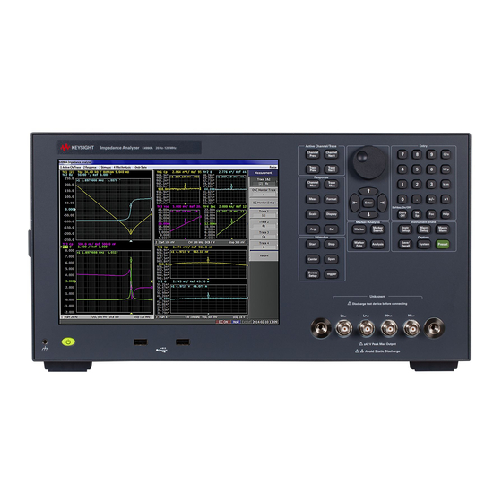
- Page 1 Keysight E4990A Impedance Analyzer Installation Guide...
-
Page 2: Safety Notices
EULA. governed by United States and Declaration of Conformity Keysight shall be under no obligation international copyright laws. to update, revise or otherwise modify Trademark Acknowledgments Declarations of Conformity for this the Software. -
Page 3: Caution
When you notice any of the unusual conditions listed below, immediately terminate operation and disconnect the power cable. Contact your local Keysight Technologies sales representative or authorized service company for repair of the instrument. If you continue to operate without repairing the instrument, there is a potential fire or shock hazard to the operator. -
Page 4: Manufacturer's Declaration
European Directives, and carries the CE marking accordingly: • The Low Voltage Directive 2006/95/EC • The EMC Directive 2004/108/EEC To obtain Declaration of Conformity, please contact your local Keysight Technologies sales office, agent or distributor. Safety Notice Supplement • This equipment complies with EN/IEC61010- 1:2001. -
Page 5: General Safety Precautions
The E4990A complies with INSTALLATION CATEGORY II as well as POLLUTION DEGREE 2 in IEC61010-1. The E4990A is an INDOOR USE product. The LEDs in the E4990A are Class 1 in accordance with IEC60825-1, CLASS 1 LED PRODUCT. • Ground the Instrument To avoid electric shock, the instrument chassis and cabinet must be grounded with the supplied power cable’s grounding prong. -
Page 6: Safety Symbols
To avoid the danger of introducing additional hazards, do not install substitute parts or perform unauthorized modifications to the instrument. Return the instrument to a Keysight Technologies Sales and Service Office for service and repair to ensure that safety features are maintained in operational condition. -
Page 7: Exclusive Remedies
International Standards Organization members. Exclusive Remedies The remedies provided herein are Buyer’s sole and exclusive remedies. Keysight Technologies shall not be liable for any direct, indirect, special, incidental, or consequential damages, whether based on contract, tort, or any other legal theory. -
Page 8: Manuals For E4990A
E4990A help. It allows you to get information about the selected softkey by pressing the Help key in the E4990A or by pressing F1 in a keyboard attached to the E4990A or by clicking the help button in a dialog box. With context sensitive help, users can receive information quickly about the area the user is working in the firmware of the E4990A. -
Page 9: Table Of Contents
Initial Registration of E4990A........ - Page 10 Procedure to execute the factory recovery ........25 Keysight E4990A Installation Guide...
-
Page 11: Introduction
Step 3. By referring to the furnished contents list, check that all packaged items supplied with the analyzer have been received as per the specified options. Step 4. After checking, if one of the following applies, contact your nearest Keysight Technologies sales and service office. -
Page 12: Environmental Requirements
4. A fault has been detected in the subsequent operation check of the analyzer. If an abnormality is detected in step 1, contact the company that transported the analyzer as well as your nearest Keysight Technologies sales and service office. Environmental Requirements Set up theE4990A where the following environmental requirements are met. -
Page 13: Protection Against Electrostatic Discharge (Esd)
20, the power supply is disconnected by removing the power cable’s connector plug from either the AC outlet or the E4990A unit. When installing the E4990A, ensure that there is sufficient free space around the unit to permit quick disconnection of the plug (from AC outlet or E4990A unit) in case of emergency. -
Page 14: Installing Front Handles/Rack Mounting Flanges
Environmental Requirements Installing Front Handles/Rack Mounting Flanges The E4990A can be installed on a workbench or on a rack. This section describes how to install the front handles (Option 1CN) used for moving or transporting the instrument, and how to install the analyzer in an equipment rack as part of a measurement system (Option 1CM: without the handles, Option 1CP: with the handles). - Page 15 E4990A. The rack- mount kit (Option 1CM) includes two flanges (locking side plates) for mounting the E4990A on a rack (482.6 mm/19 inches) conforming to the EIA Standard. Option 1CP comes with both, the handle kit and rack- mount kit.
- Page 16 Introduction Environmental Requirements Step 3. (Option 1CM/Option 1CP). Remove the four bottom feet of the E4990A (lift the bar marked TAB on the inner side of the foot and slide the foot towards the bar). Step 4. (Option 1CM/Option 1CP). Mount the E4990A on the rack.
-
Page 17: Power Supply
1. Switched automatically by the E4990A in conformity to the voltage used. Verification and Connection of Power Cable The three-wire power cable attached to the E4990A has one wire serving as the ground. Using this power cable allows the E4990A to be grounded, thereby protecting you against any potential electrical shock from the power outlet. -
Page 18: Blown Fuses
Blown Fuses If the fuse appears to have blown during operation, this instrument may be subject to failure and must be repaired. For any assistance, contact Keysight Technologies Customer contact center listed at the end of this guide. The E4990A uses the following fuse types: UL/CSA Type, Slow- Blo, 10 A- 250 Vac. -
Page 19: Starting The E4990A
Normal operation is confirmed by the self- test if no error message appears. Turning the Power OFF Step 1. To turn OFF the power of the E4990A, first, press this standby switch or send a shutdown command from the external controller to activate the shutdown process (the process of software and hardware necessary to turn OFF the power supply). -
Page 20: Disconnection From Supply Source
Line switch (Always ON) and power cable receptacle Disconnection from Supply Source The power supply of the E4990A is cut off by disconnecting the plug of the power cable (on either AC outlet side or E4990A side). When it is necessary to disconnect the power supply in order to avoid shock hazards, etc., pull out the... - Page 21 “Ensuring Adequate Free Space around Analyzer for Immediate Disconnection of Power Cable in Case of Emergency” on page When turning the power OFF under normal circumstances, always follow the methods described in “Turning the Power OFF” on page Keysight E4990A Impedance Analyzer...
-
Page 22: Initial Registration Of E4990A
Initial Registration of E4990A Initial Registration of E4990A When you start up the E4990A for the first time, you need to perform the initial registration of the Windows operating system of the E4990A. When the Windows agreement message box appears, click Agree. The rest of the procedure runs automatically. -
Page 23: Troubleshooting
Keysight E4990A Impedance Analyzer Installation Guide Troubleshooting This chapter describes the troubleshooting process during start up and the procedure of the operating system (OS) recovery when the Windows OS has been damaged. Troubleshooting during Startup When you encounter problems during start up, see Table 2-1. -
Page 24: System Recovery
However, Keysight recommends backing them up before executing system recovery for precautionary purposes. For more information on backup, refer to “Backing Up the Data” as described in E4990A Online Help. 1. The default setting of the hard disk is recovered during the system recovery. For the hard disk that had failed earlier and had been replaced (after purchase), its default setting may not be the same as the factory state. - Page 25 Step 2. Disconnect all of the USB device from the USB ports. Step 3. Connect the keyboard to the E4990A. Step 4. Press the standby switch of the E4990A to turn it ON. Step 5. When the screen as shown in the figure below appears, select Keysight Recovery System and press [Enter].
- Page 26 Figure 2-3 System recovery confirmation screen Step 9. The progress of the system configuration is displayed on the screen. The recovery takes a few minutes depending on the amount of data. Figure 2-4 System configuration progress screen Keysight E4990A Impedance Analyzer...
- Page 27 Step 11. After the restart, execute initial registration. For information on the execution procedure, refer to “Initial Registration of E4990A” on page Never turn OFF the power during the system recovery because doing so may cause serious damage to the E4990A. Keysight E4990A Impedance Analyzer...
- Page 28 Troubleshooting System Recovery Keysight E4990A Impedance Analyzer...
- Page 29 OFF starting the E4990A system installing rack mounting flanges System Recovery how to execute factory recovery Keysight E4990A Installation Guide...
- Page 30 Index Keysight E4990A Installation Guide...
- Page 31 This information is subject to change without notice. © Keysight Technologies 2014-2018 Edition 3, July 2018 *E4990-90010* E4990-90010 www.keysight.com...
Need help?
Do you have a question about the E4990A and is the answer not in the manual?
Questions and answers