Keysight E4980A Service Manual
Precision lcr meter
Hide thumbs
Also See for E4980A:
- User manual (519 pages) ,
- Technical overview (28 pages) ,
- User manual (529 pages)
Table of Contents
Advertisement
Quick Links
Advertisement
Table of Contents
Troubleshooting

Subscribe to Our Youtube Channel
Related Manuals for Keysight E4980A


Summary of Contents for Keysight E4980A
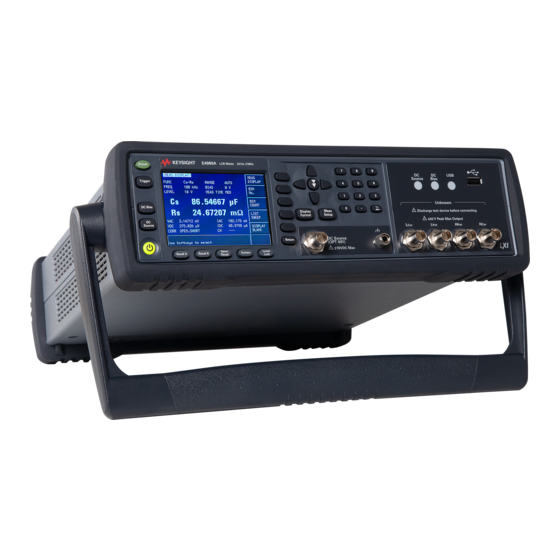
- Page 1 Keysight E4980A/E4980AL Precision LCR Meter Service Guide...
-
Page 2: Safety Notices
The hardware and/or software specifically in writing elsewhere in the United States and international described in this document are EULA. Keysight shall be under no copyright laws. furnished under a license and may be obligation to update, revise or otherwise... -
Page 3: Caution
When you notice any of the unusual conditions listed below, immediately terminate operation and disconnect the power cable. Contact your local Keysight Technologies sales representative or authorized service company for repair of the instrument. If you continue to operate without repairing the instrument, there is a potential fire or shock hazard to the operator. -
Page 4: Manufacturer's Declaration
European Directives, and carries the CE marking accordingly: • The Low Voltage Directive 2006/95/EC • The EMC Directive 2004/108/EEC To obtain Declaration of Conformity, please contact your local Keysight Technologies sales office, agent or distributor. Keysight E4980A/E4980AL Precision LCR Meter... -
Page 5: Safety Notice Supplement
• This equipment is tested in stand-alone condition and in combination with the accessories supplied by Keysight Technologies against the requirement of the standards described in the Declaration of Conformity. If it is used as a system component, compliance of related regulations and safety requirements are to be confirmed by the builder of the system. -
Page 6: General Safety Precautions
The E4980A/E4980AL complies with INSTALLATION CATEGORY II as well as POLLUTION DEGREE 2 in IEC61010-1. The E5061B is an INDOOR USE product. The LEDs in the E4980A/E4980AL are Class 1 in accordance with IEC60825-1, CLASS 1 LED PRODUCT. • Ground the Instrument To avoid electric shock, the instrument chassis and cabinet must be grounded with the supplied power cable’s grounding prong. -
Page 7: Safety Symbols
Certification Keysight Technologies certifies that this product met its published specifications at the time of shipment from the factory. Keysight Technologies further certifies that its calibration measurements are traceable to the United States National Institute of Standards and Technology, to the extent allowed by the Institution’s calibration facility or by the calibration facilities of other... -
Page 8: Documentation Warranty
Keysight shall not be liable for errors or for incidental or consequential damages in connection with the furnishing, use, or performance of this document or any information contained herein. -
Page 9: Manuals For E4980A/E4980Al
Caution Manuals for E4980A/E4980AL Manuals for E4980A/E4980AL Keysight provides the following three manuals for E4980A/E4980AL. The latest version of all documentations can be downloaded from http://www.keysight.com/manual/e4980a. Installation Guide The installation guide (this manual) provides start up setup information when you use the E4980A/E4980AL for the first time and troubleshooting information when the Windows cannot be boot up. - Page 10 Caution Manuals for E4980A/E4980AL Keysight E4980A/E4980AL Precision LCR Meter...
-
Page 11: Table Of Contents
Manuals for E4980A/E4980AL ........ - Page 12 Performance test failure troubleshooting .........65 Keysight E4980A/E4980AL Service Guide...
- Page 13 Removal Procedure ............88 Keysight E4980A/E4980AL Service Guide...
- Page 14 Replacement Procedure ..........109 Keysight E4980A/E4980AL Service Guide...
- Page 15 How to update E4980A/ E4980AL firmware using USB/GPIB interface... . . 117 Update the E4980A/ E4980AL firmware using USB cable ......119 Required Equipment.
- Page 16 S ..............135 Keysight E4980A/E4980AL Service Guide...
-
Page 17: General Information Organization Of Service Guide
Keysight E4980A/E4980AL Precision LCR Meter Service Guide General Information This Service Guide is a guide to servicing the E4980A & E4980AL 20Hz to 300kHz/ 500kHz/ 1MHz/ 2MHz Precision LCR Meter. The Service Guide provides information about performance test, adjustment, troubleshooting, and repairing the instrument. - Page 18 E4980A/ E4980AL manufactured earlier than the current printing date of this manual. The information in this manual applies directly to E4980A/ E4980AL units with the serial number that is printed on the title page of this manual.
-
Page 19: Instruments Covered By This Manual
Manual Changes supplement. The supplement for this manual is identified by this manual’s printing data and is available from Keysight Technologies. If the serial prefix or number of an instrument is lower than that on the title page of this manual, see Appendix A, Manual Changes. -
Page 20: Required Equipment
General Information Required Equipment Required Equipment Table 1-1 lists the recommended equipment for performance test, adjustment and troubleshooting for E4980A/ E4980AL. Table 1-1 Recommended Test Equipment Equipment Critical Specifications Recommended Model Qty. Frequency Counter Frequency Range: 1 MHz Keysight 53181A Time Base Error <... -
Page 21: Performance Test
Keysight E4980A/E4980AL Precision LCR Meter Service Guide Performance Test This chapter provides the outline of the E4980A/ E4980AL performance tests. Introduction This chapter provides the performance tests outline for Keysight E4980A/ E4980AL. The performance test names are listed in Table 2-1. -
Page 22: Test Equipment Required
Performance Test Introduction Table 2-1 List of the E4980A/ E4980AL performance tests Para. Title AC Signal Level Accuracy Test Impedance Measurement Accuracy Test DCR Measurement Accuracy Test Test Equipment Required The required equipment for the performance test is listed in Table 1-1. -
Page 23: Individual Test Description
This test checks the DC source level accuracy of the E4980A/ E4980AL DC source port output signal. 3. DC Bias Level Accuracy Test Description This test checks the DC bias level accuracy of the E4980A/ E4980AL DC bias signal. 4. DC Bias V Level Monitor Accuracy Test Description This test checks the DC bias V level monitor accuracy of the E4980A/ E4980AL. -
Page 24: Ac Signal Level Accuracy Test
Performance Test Individual Test Description 7. AC Signal Level Accuracy Test Description This test checks the AC signal level accuracy of the E4980A/ E4980AL output signal. 8. Impedance Measurement Accuracy Test Description This test checks the impedance measurement accuracy of the E4980A/ E4980AL. -
Page 25: Adjustment
Intentional interruption of the protective ground system for any reason is prohibited. Warm-up for Adjustment Warm-up the E4980A/ E4980AL for at least 30 minute before performing any of the following Adjustment procedures to ensure proper results and correct instrument operation. -
Page 26: Required Adjustment After Replacing Assembly
After replacing the following assembly, the adjustment items described in Table 3-1 are required. The adjustment must be performed by Keysight’s qualified service personnel. If you need the adjustment for your E4980A/ E4980AL, it should be sent to the nearest Keysight Technologies service office. Table 3-1... -
Page 27: Dc Bias Adjustment
The purpose of this procedure is to adjust the impedance measurement. AC Level Monitor Adjustment The purpose of this procedure is to adjust the AC level monitor. OSC Level Adjustment The purpose of this procedure is to adjust the OSC level. Keysight E4980A/E4980AL Precision LCR Meter... - Page 28 Adjustment Required Adjustment after Replacing Assembly Keysight E4980A/E4980AL Precision LCR Meter...
-
Page 29: Troubleshooting
Keysight E4980A/E4980AL Precision LCR Meter Service Guide Troubleshooting This chapter provides the procedure to isolate a faulty assembly in the E4980A/ E4980AL. Introduction These servicing instructions are for use by qualified personnel only. To avoid possible electrical shock, do not perform any servicing unless you are qualified to do so. -
Page 30: To Troubleshoot The Instrument
E4980A/ E4980AL. Step 1. Turn the E4980A/ E4980AL power on With the E4980A/ E4980AL plugged in and the power turned off, the front panel orange standby LED should be on. When the front panel power switch is turned on, the orange LED should go out and the yellow-green LED should come on. - Page 31 Problems on Measurement Performance and Measurement Result Power on Performance test Power on test Go to Performance Test Performance test pass? Failure Troubleshooting Go to Troubleshooting Power on test pass? Using Service Function Keysight E4980A/E4980AL Precision LCR Meter...
-
Page 32: Power On Sequence Troubleshooting
Power Requirements in Appendix B. Check the Power Supply Unit Output Step 1. Remove the E4980A/ E4980AL’s outer cover. Step 2. Turn the E4980A/ E4980AL power on. Step 3. Measure the output voltage (+3.3, +5, +12, -12 V) of the power supply unit using a voltmeter with a small probe. - Page 33 Troubleshooting Power On Sequence Troubleshooting Figure 4-2 Output Voltage Location For MY46516000 (E4980A), SG46500500 (E4980A GSA), MY54304301 (E4980AL), SG54300100 (E4980AL GSA) and below. P501 P3 +12V -12V +3.3V +12V +3.3V +3.3V +12V P6 -12V Keysight E4980A/E4980AL Precision LCR Meter...
- Page 34 Troubleshooting Power On Sequence Troubleshooting Figure 4-3 Output Voltage Location For MY46516001 (E4980A), SG46500501 (E4980A GSA), MY54304302 (E4980AL), SG54300101 (E4980AL GSA) and above. • If the voltmeter reading is not within the following limits, replace the power supply unit. Table 4-1...
-
Page 35: Check Booting Process
If the power on sequence has a problem despite it being powered from the power supply unit properly, check the following events in this order. 1. With the E4980A/ E4980AL plugged in and the power turned off, the orange standby LED should be on. If the orange LED doesn’t light, check the key flex circuit, display interface board, A1 board, and relevant cables. -
Page 36: Troubleshooting Using Service Function
Power On Test The Power On Test always takes place once the E4980A/ E4980AL is turned on. When a failure is detected, a message "Power on test failed" is displayed in the system message area and the normal measurement screen does not appear (Service Mode). - Page 37 Troubleshooting Using Service Function Figure 4-4 SELF TEST Page Choosing a Test Item Functional Description E4980A/ E4980AL can run the following self tests: The tests of SYSTEM, USER DATA, and BATTERY are also performed by the power on test. Test item Description...
- Page 38 Checks the scanner interface. (Visual checks only; no result INTERFACE shown on screen.) Executing the self-test from the front panel The self-test of the E4980A/ E4980AL can be executed from the front panel. The steps are given below. Self-test procedure Step 4. Press [System] - SELF TEST Step 5.
-
Page 39: Service Page
SERVICE softkey opens the SERVICE page. This page is read-only. This page displays the system information of E4980A/ E4980AL and allows you to save the displayed information into the USB memory, but does NOT allow you to modify or delete the information. - Page 40 SERVICE page. Monitor Description Information POWER ON Displays how many times E4980A/ E4980AL have been started up and its cumulative power-on time. SYSCAL REV Displays the program revision of the adjustment for the E4980A/ E4980AL. SYSCAL Displays the date of the last adjustment for the E4980A/ E4980AL.
- Page 41 SYST[5]: 0 DATA[1]: 0 DATA[2]: 0 DATA[3]: 0 DATA[4]: 0 OPT[1]: 0 OPT[2]: 0 OPT[3]: 0 OPT[4]: 0 OPT[5]: 0 OPT[6]: 0 OPT[7]: 0 A1[1]: -1.187504864E+01 A1[2]: +1.184382915E+01 A1[3]: +5.098754883E+00 1. Result for firmware revision A.xx.xx Keysight E4980A/E4980AL Precision LCR Meter...
- Page 42 A3[1]: -4.189105189E-05 A3[2]: -8.715481204E-01 A3[3]: +8.746015586E-01 A3[4]: -7.700712127E-01 A3[5]: +2.887844449E-01 USER[1]: 0 USER[2]: 0 USER[3]: 0 USER[4]: 0 BATT[1]: +3.247070313E+00 +3.750000000E+01 +4.474563461E-01 +4.404803338E-01 1. Result for firmware revision A.xx.xx 2. Result for firmware revision B.xx.xx Keysight E4980A/E4980AL Precision LCR Meter...
-
Page 43: Power On Test / Self Test Failure Troubleshooting
A1 FPGA check 0x01 A2 FPGA check 0x02 A1 Revision check 0x04 A2 Revision check 0x08 A3 Revision check 0x10 Data System Data 0x01 SysCal Data 0x02 Flash File system 0x04 check Test Limit Data 0x08 Keysight E4980A/E4980AL Precision LCR Meter... - Page 44 Option 201 Off 0x04 check Option 301 Off check Option 201 On 0x08 check Option 301 On check Option 301 Off 0x10 check Option consistency check Option 301 On 0x20 check Option consistency 0x40 check Keysight E4980A/E4980AL Precision LCR Meter...
- Page 45 0x02 A1_DCBUS_P5V 0x04 A1_DCBUS_P3.3V 0x08 0x10 A1_DCBUS_P2.5V A1_DCBUS_P1.2V_M 0x20 A1_DCBUS_STANBY A1_DCBUS_P1.2V 0x40 A1_DCBUS_STANBY A2_DCBUS_GND 0x01 A2_DCBUS_PM5V 0x02 A2_DCBUS_P3V 0x04 A2_DCBUS_P10V 0x08 A2_DCBUS_M10V 0x10 A2_DCBUS_TEMP 0x20 A3_DCBUS_GND 0x01 A3_DCBUS_N50V 0x02 A3_DCBUS_P50V 0x04 A3_DCBUS_N12V 0x08 A3_DCBUS_TEMP 0x10 Keysight E4980A/E4980AL Precision LCR Meter...
- Page 46 2 . O n l y f o r f i r m w a r e r e v i s i o n B . x x . x x ###: Most suspicious assembly ##: Suspicious assembly #: Possible faulty assembly Keysight E4980A/E4980AL Precision LCR Meter...
-
Page 47: Function Specific Troubleshooting
Function Specific Troubleshooting Function Specific Troubleshooting If the E4980A/ E4980AL exhibits a failure symptom that is related to a specific function or control such as a front panel key control, display, data storage, remote control interface, external trigger, isolate the trouble using the Function Specific Troubleshooting procedures described below. -
Page 48: To Check The Front Panel
Step 5. To exit the DISPLAY test, press TEST STOP, and then press [Return]. • If the LCD display has a problem, check the LCD and the display interface board. • If the LCD is not illuminated with backlight, check the inverter board. Keysight E4980A/E4980AL Precision LCR Meter... -
Page 49: To Check The Front Usb Port
To Check the External Trigger Input Procedure Step 1. Press [Preset] - CLEAR SETTING - OK to initialize the E4980A/ E4980AL. Step 2. Press [Meas Setup]. Step 3. Using the cursor keys, select the TRIG field, and then select EXTsoftkey. -
Page 50: To Check The Lan
Figure 4-7. The letters x represent the IP address and subnet mask of the E4980A/ E4980AL. The letter y is different from the IP address of the E4980A/ E4980AL. Press the OK button. Then, restart the external PC. - Page 51 Function Specific Troubleshooting Figure 4-7 Network Dialog Box (“IP Address” Tab) Step 8. By clicking “OK” button, the network settings take effect. Verify the E4980A/ E4980AL LAN settings and response to a command from the external computer as follows: a. On the external computer, click "Start" button in the Windows Start menu bar using a mouse.
-
Page 52: To Check The Gpib
To Check the GPIB Procedure Perform the E4980A/ E4980AL performance test program. If the controller cannot detect the E4980A/ E4980AL, the problem seems in the PPMC PCA or the connection of the GPIB cable. To Check the USB (USBTMC) Interface Card Procedure Connect the USB cable between the controller PC and the E4980A/ E4980AL. - Page 53 Troubleshooting Function Specific Troubleshooting Procedure Step 1. Disconnect the power cable from the E4980A/ E4980AL and allow 1 minute for the internal capacitors to discharge. Dangerous energy/voltage exists when the E4980A/ E4980AL is in operation, and for a time after it is powered down. Allow 1 minutes for the internal capacitors to discharge.
- Page 54 (S1) of the handler interface board. Step 4. Replace the handler interface board. Step 5. Turn the E4980A/ E4980AL ON. Step 6. Connect the handler interface connector on the E4980A/ E4980AL’s rear panel to the handler simulator as shown in Figure 4-11.
- Page 55 Step 11. Press the EXECUTE - TEST START softkeys to execute the HANDLER INTERFACE test. Step 12. Confirm that the LEDs on the handler simulator turn ON in accordance with the E4980A/ E4980AL’s output signals displayed on the LCD. The LEDs turns ON light in the sequence shown in Figure 4-12.
- Page 56 Step 13. Press the TEST STOP softkey. Do not execute any SELF TEST except for the Handler Interface Test or the E4980A/ E4980AL will become inoperative. Step 14. Return the jumper and switch settings on the handler interface board to their original settings.
-
Page 57: To Check The Scanner Interface Function (Option 301 Only)
1 k Standard Keysight 42030A (42037A) Procedure Step 1. Disconnect the power cable from the E4980A/ E4980AL and allow 1 minute for the internal capacitors to discharge. Dangerous energy/voltage exists when the E4980A/ E4980AL is in operation, and for a time after it is powered down. Allow 1 minutes for the internal capacitors to discharge. - Page 58 Switches Setting Table 4-8 Setting Bit Switch (S1) Default 1. For bits 1 to 3 of bit switch S1, only one bit can be turned on at one time. Table 4-9 Setting Bit Switch (S2) Default Keysight E4980A/E4980AL Precision LCR Meter...
- Page 59 Step 6. Connect the scanner simulator to the scanner interface connector on the E4980A/ E4980AL’s rear panel shown in Figure 4-14. Step 7. Connect the 1 k standard to the UNKNOWN terminal on the E4980A/ E4980AL’s front panel. Step 8. Turn the E4980A/ E4980AL ON. Step 9. Press [System].
-
Page 60: To Check The Bias Current Interface Function (Option 002 Only)
INTERFACE test. Step 14. Confirm that LEDs on the scanner simulator board turn ON in accordance with the E4980A/ E4980AL settings displayed in the LCD. Step 15. Press the TEST STOP softkey. Do not execute any SELF TEST except for the Scanner Interface Test or the E4980A/ E4980AL will become inoperative. - Page 61 Troubleshooting Function Specific Troubleshooting Figure 4-15 Bias Interface Simulator Keysight E4980A/E4980AL Precision LCR Meter...
- Page 62 DC power for the bias interface simulator can be supplied from the E4980A/ E4980AL instead of from an external DC power supply. Step 3. Interconnect the bias interface simulator and bias interface connector on the rear panel of the E4980A/ E4980AL with the bias interface cable as shown in Figure 4-16.
- Page 63 Figure 4-17. Figure 4-17 Bias Current Interface Function Test Step 14. Confirm that “DI0 TO 7” and “DI8 TO 15” on the LCD of the E4980A/ E4980AL display hexadecimal number “ff”. Keysight E4980A/E4980AL Precision LCR Meter...
- Page 64 “0” is displayed by “DI0 TO 7” and “DI8 TO 15”. The states of S1 (DI0 TO 7) and S2 (DI8 TO 15) are displayed as a hexadecimal number on the E4980A/E4980AL’s LCD. Step 16. Press the TEST STOP softkey.
-
Page 65: Performance Test Failure Troubleshooting
Performance test failure troubleshooting This section describes the adjustment and troubleshooting procedures used when the E4980A/ E4980AL fails the performance tests. If the performance of the instrument is critical for the test limits and seems to be adjustable, perform first the adjustment(s) related to the failed test. When the test result is far from the tolerance of the test or the performance is not adjustable, isolate the faulty assembly in accordance with the "Performance tests failure troubleshooting... -
Page 66: Adjustment Failure Troubleshooting
DC Level V Monitor adjustment DC Level I Monitor adjustment DC Source adjustment DCR adjustment Impedance adjustment AC level Monitor adjustment OSC Level adjustment ###: Most suspicious assembly ##: Suspicious assembly #: Possible faulty assembly Keysight E4980A/E4980AL Precision LCR Meter... -
Page 67: Performance Test Failure Troubleshooting
DC Bias I Level Monitor Accuracy Test AC Signal Level Monitor Accuracy Test AC Signal Level Accuracy Test Impedance Measurement Accuracy Test DCR Measurement Accuracy Test ###: Most suspicious assembly ##: Suspicious assembly #: Possible faulty assembly Keysight E4980A/E4980AL Precision LCR Meter... - Page 68 Troubleshooting Performance test failure troubleshooting Keysight E4980A/E4980AL Precision LCR Meter...
-
Page 69: Replaceable Parts
Keysight E4980A/E4980AL Precision LCR Meter Service Guide Replaceable Parts Replaceable Parts The replaceable part information is no longer maintained. Please contact Keysight service center on service related request. - Page 70 Replaceable Parts Replaceable Parts Keysight E4980A/E4980AL Precision LCR Meter...
-
Page 71: Replacement Procedure
This chapter provides procedure for removing and replacing the major assemblies in the E4980A/ E4980AL. Replacing an Assembly The following steps show the sequence for replacing an assembly in a E4980A/ E4980AL Signal Source Analyzer. 1. Identify the faulty group. Refer to Chapter 4, “Troubleshooting.”... -
Page 72: Required Tools
Replacement Procedure Required Tools Required Tools The following tools are required for repair of E4980A/ E4980AL. Table 6-1 Required Tools Assembly Torque screwdriver Box torque wrench 5.5 mm 7 mm 3/8 in. 5/8 in. 3/4 Rack Module Top A3 Analog Daughter Board ... -
Page 73: 3/4 Rack Module Top Replacement
Figure 6-3 and for this procedure. Step 1. Disconnect the power cable from the E4980A/ E4980AL. Step 2. Remove the handle, front bumper and rear bumper. (item 1, 2, 3) To remove the handle, rotate the handle to a vertical position and pull the arms outwards. - Page 74 Replacement Procedure 3/4 Rack Module Top Replacement Figure 6-1 3/4 Rack Module Top Removal (1 of 3) Keysight E4980A/E4980AL Precision LCR Meter...
- Page 75 Replacement Procedure 3/4 Rack Module Top Replacement Figure 6-2 3/4 Rack Module Top Removal (2 of 3) Keysight E4980A/E4980AL Precision LCR Meter...
- Page 76 Replacement Procedure 3/4 Rack Module Top Replacement Figure 6-3 3/4 Rack Module Top Removal (3 of 3) Keysight E4980A/E4980AL Precision LCR Meter...
-
Page 77: A3 Analog Daughter Board Replacement
When you fasten the A3 Analog Daughter Board with the four TORX T10 screws, set screwdriver's torque to 8.7 in-lb. When you connect the LCD Cable to the A1 Mother Board, make sure the LCD Cable lies beneath the Analog Source Cable. Keysight E4980A/E4980AL Precision LCR Meter... - Page 78 Replacement Procedure A3 Analog Daughter Board Replacement Figure 6-4 A3 Analog Daughter Board Removal Keysight E4980A/E4980AL Precision LCR Meter...
-
Page 79: A2 Analog Board Replacement
When you fasten the A2 Analog Board with the five 5/8 inch nuts and washers, set box torque wrench's torque to 17.4 in-lb. When you fasten the A2 Analog Board with the four 7 mm Standoff, set box torque wrench's torque to 8.7 in-lb. Keysight E4980A/E4980AL Precision LCR Meter... - Page 80 Replacement Procedure A2 Analog Board Replacement Figure 6-5 A2 Analog Board Removal Keysight E4980A/E4980AL Precision LCR Meter...
-
Page 81: Front Panel Assembly Removal
“A2 Analog Board Replacement” on page Replacement Procedure The Front Panel Assembly replacement process is reverse order of the A2 Analog Board removal process. Refer to removal procedure of the “A2 Analog Board Replacement” on page Keysight E4980A/E4980AL Precision LCR Meter... -
Page 82: Option Interface Replacement
When you fasten the option panel with the two TORX T10 screws, set screwdriver's torque to 8.7 in-lb. When you fasten the interface card with the two TORX T10 screws, set screwdriver's torque to 8.7 in-lb. Keysight E4980A/E4980AL Precision LCR Meter... - Page 83 Replacement Procedure Option Interface Replacement Figure 6-6 Option Interface Removal Keysight E4980A/E4980AL Precision LCR Meter...
-
Page 84: Ppmc Pca Replacement
Step 7. Remove the USB gasket (item 5) from the PPMC PCA. Replacement Procedure Step 1. Reverse the order of the removal procedure. When you fasten the PPMC PCA with the four TORX T8 screws, set screwdriver's torque to 3 in-lb. Keysight E4980A/E4980AL Precision LCR Meter... - Page 85 Replacement Procedure PPMC PCA Replacement Figure 6-7 PPMC PCA Removal Keysight E4980A/E4980AL Precision LCR Meter...
-
Page 86: A1 Mother Board Replacement
6-8, and set screwdriver's torque to 4.35 in-lb for other screws. When you connect the LCD Cable to the A1 Mother Board, make sure the LCD Cable is at the bottom of the Analog Source Cable. Keysight E4980A/E4980AL Precision LCR Meter... - Page 87 Replacement Procedure A1 Mother Board Replacement Figure 6-8 A1 Mother Board Replacement Keysight E4980A/E4980AL Precision LCR Meter...
-
Page 88: Power Supply Assembly Replacement
Do not pull out the power cable (P/N : E4980-61601) from the Power Supply Assembly when you detach the Power Supply Assembly. There is a possibility that the Power Supply Assembly could break when the power cable is forcibly pulled out. (Refer to sub-figure in Figure 6-9) Keysight E4980A/E4980AL Precision LCR Meter... -
Page 89: Replacement Procedure
When you fasten the Power Supply Assembly with the 5.5 mm Standoff, set box torque wrench's torque to 7 in-lb. When you replace the Power Supply Assembly with a new one, use a new power cable (P/N : E4980-61601).Note Keysight E4980A/E4980AL Precision LCR Meter... - Page 90 Replacement Procedure Power Supply Assembly Replacement Figure 6-9 Power Supply Assembly Removal Keysight E4980A/E4980AL Precision LCR Meter...
-
Page 91: Base Plate Replacement
Step 12. Remove the Rack Module Bottom from the Base Plate. Step 13. Remove the Rear Panel as described from Step 9 “Rear Panel Step 11 Assembly Replacement” on page Step 14. Remove the Base Plate from the Rear Panel. Keysight E4980A/E4980AL Precision LCR Meter... -
Page 92: Replacement Procedure
When you fasten the Base Plate with the seven TORX T20 screws, set screwdriver's torque to 21.1 in-lb. When you fasten the Shield Angle with the two TORX T10 screws, set screwdriver's torque to 8.7 in-lb. Keysight E4980A/E4980AL Precision LCR Meter... - Page 93 Replacement Procedure Base Plate Replacement Figure 6-10 Base Plate Board Removal Keysight E4980A/E4980AL Precision LCR Meter...
-
Page 94: Rear Panel Assembly Replacement
Step 9. Remove the one TORX T20 screw (item 1) fastening the ground cable. Step 10. Remove the five TORX T10 screws (item 2) fastening the Rear Panel Assembly. Step 11. Remove the Rear Panel Assembly from the Base Plate. Keysight E4980A/E4980AL Precision LCR Meter... -
Page 95: Replacement Procedure
When you fasten the Rear Panel with the five TORX T10 screws, set screwdriver's torque to 8.7 in-lb. When you fasten the ground cable with the TORX T20 screw, set screwdriver's torque to 21.1 in-lb. Figure 6-11 Rear Panel Assembly Removal Keysight E4980A/E4980AL Precision LCR Meter... -
Page 96: Fan Assembly Replacement
If you can not push the rivets out easily, push the rivets out using a flat-edge driver. Step 4. Remove the Fan Assembly (item 3) from the Rear Panel. Replacement Procedure Step 1. Reverse the order of the removal procedure. When you replace the Fan Assembly, use new rivets. Keysight E4980A/E4980AL Precision LCR Meter... - Page 97 Replacement Procedure FAN Assembly Replacement Figure 6-12 FAN Assembly Removal Keysight E4980A/E4980AL Precision LCR Meter...
-
Page 98: Gpib Cable Replacement
Step 4. Remove the GPIB Cable (item 3) from the Rear Panel Assembly. Replacement Procedure Step 1. Reverse the order of the removal procedure. When you fasten the GPIB Cable with the two 7 mm standoff, set box torque wrench's torque to 8.7 in-lb. Keysight E4980A/E4980AL Precision LCR Meter... - Page 99 Replacement Procedure GPIB Cable Replacement Figure 6-13 GPIB Removal Keysight E4980A/E4980AL Precision LCR Meter...
-
Page 100: Power Inlet Assembly Replacement
21.1 in-lb. When you fasten the Inlet Assembly with the two TORX T10 screws, set screwdriver's torque to 8.7 in-lb. Do not forget to insert the fuse in the new Inlet Assembly. Keysight E4980A/E4980AL Precision LCR Meter... - Page 101 Replacement Procedure Power Inlet Assembly Replacement Figure 6-14 POWER INLET Assembly Removal Keysight E4980A/E4980AL Precision LCR Meter...
-
Page 102: Pca E4980 Usb Replacement
Step 1. Reverse the order of the removal procedure. When you fasten the PCA E4980 USB and the ground cable with the two TORX T20 screws, set screwdriver's torque to 14 in-lb. Figure 6-15 PCA E4980 USB Removal Keysight E4980A/E4980AL Precision LCR Meter... -
Page 103: Binding Post Sgl Replacement
Step 6. Slide the Binding Post Sgl (item 3) from the Front Panel Assembly. Replacement Procedure Step 1. Reverse the order of the removal procedure. When you fasten the Binding Post Sgl with the 3/8 inch nut and washer, set box torque wrench's torque to 17.4 in-lb. Keysight E4980A/E4980AL Precision LCR Meter... - Page 104 Replacement Procedure Binding Post Sgl Replacement Figure 6-16 Binding Post Sgl Removal Keysight E4980A/E4980AL Precision LCR Meter...
-
Page 105: Inverter Replacement
Assembly. Then, remove the Inverter from the insulator. Replacement Procedure Step 1. Reverse the order of the removal procedure. When you fasten the Inverter and the insulator with the two TORX T6 screws, set screwdriver's torque to 3.05 in-lb. Keysight E4980A/E4980AL Precision LCR Meter... - Page 106 Replacement Procedure Inverter Replacement Figure 6-17 Inverter Removal Keysight E4980A/E4980AL Precision LCR Meter...
-
Page 107: Front Panel, Key Pad, And Key Flex Circuit Replacement
Step 8. Remove the Front Panel (item 3) from the Key Pad (item 4), the Window EMI Shield (item 5), the Key Flex Circuit (item 6), and the EMI Shield (item 7). Replacement Procedure Step 1. Reverse the order of the removal procedure. Keysight E4980A/E4980AL Precision LCR Meter... - Page 108 Replacement Procedure Front Panel, Key Pad, and Key Flex Circuit Replacement Figure 6-18 Front Panel, Key Pad, and Key Flex Circuit Removal Keysight E4980A/E4980AL Precision LCR Meter...
-
Page 109: Display Interface Replacement
When you fasten the LCD Display with the four TORX T6 screws, set screwdriver's torque to 3.05 in-lb. When you replace the LCD Display with a new one, stick new gaskets (P/N : E4980-25003 x 2, E4980-25004 x 2) to surroundings on the LCD Display. Keysight E4980A/E4980AL Precision LCR Meter... - Page 110 Replacement Procedure Display Interface Replacement Figure 6-19 Display Interface Removal Keysight E4980A/E4980AL Precision LCR Meter...
-
Page 111: Post-Repair Procedures
Keysight E4980A/E4980AL Precision LCR Meter Service Guide Post-Repair Procedures This chapter lists the procedures required to verify the E4980A/ E4980AL operation after an assembly is replaced with a new one. Post-Repair Procedures Table 7-1 Post Repair Procedures lists the required procedures that must be performed after the replacement of an assembly. - Page 112 DCR Measurement Accuracy Test (for opt Impedance Adjustment 001) AC Level monitor Adjustment OSC Level Adjustment USB Board No adjustment needed Inspect the booting process, and power on test result. “To Check the Front USB port” on page 49 Keysight E4980A/E4980AL Precision LCR Meter...
- Page 113 Function (Option 301 only)” on page 57 Bias Current I/F No adjustment needed Inspect the booting process, and power on (option 002) test result. “To Check the Bias Current Interface Function (Option 002 only)” on page 60 Keysight E4980A/E4980AL Precision LCR Meter...
- Page 114 Post-Repair Procedures Post-Repair Procedures Keysight E4980A/E4980AL Precision LCR Meter...
-
Page 115: A.manual Changes
E4980A/E4980AL manufactured earlier than the current printing date of this manual. The information in this manual applies directly to E4980A/E4980AL units with the serial number that is printed on the title page of this manual. - Page 116 Manual Changes Manual Changes Keysight E4980A/E4980AL Precision LCR Meter...
-
Page 117: B.firmware Update
USB/GPIB interface. Step 1. Connect the USB/GPIB interface from the USB terminal in your computer to the GPIB terminal in the E4980A/ E4980AL rear panel. Then turn the E4980A/ E4980AL on. Step 2. Copy the following file from Keysight Technologies web site to the temporary work folder in your computer’s HDD. - Page 118 Firmware Update Update the E4980A/ E4980AL firmware using USB/GPIB interface Step 7. Press System key on the E4980A/ E4980AL front panel to check the firmware revision. Keysight E4980A/E4980AL Precision LCR Meter...
-
Page 119: Update The E4980A/ E4980Al Firmware Using Usb Cable
E4980A/ E4980AL. Then, press the Enter key. Step 6. Wait a few minutes until the command prompt is displayed again. Step 7. Press System key on the E4980A/ E4980AL front panel to check the firmware revision. Keysight E4980A/E4980AL Precision LCR Meter... - Page 120 Firmware Update Update the E4980A/ E4980AL firmware using USB cable Keysight E4980A/E4980AL Precision LCR Meter...
-
Page 121: C.power Requirement
Use the fuse that meets the following specifications. UL/CSA type, Slo-Blo, 5x20mm miniature fuse, 3A 250V (part number: 2110-1017) Spare fuses are available from Keysight Technologies sales office. To check or replace the fuse, disconnect the power cable and pull out the fuse holder (refer Figure... -
Page 122: Power Requirements
Power Requirements Figure C-2 Removing the fuse Power Requirements The E4980A/ E4980AL requires the following power source. Voltage : 90 to 132 Vac, 198 to 264 Vac Frequency : 47 to 63 Hz Power : 150 VA maximum Power Cable In accordance with international safety standards, this instrument is equipped with a three-wire power cable. - Page 123 Power Requirement Power Requirements Figure C-3 Power Cable Supplied Keysight E4980A/E4980AL Precision LCR Meter -123...
- Page 124 Power Requirement Power Requirements Keysight E4980A/E4980AL Precision LCR Meter...
-
Page 125: D.error Messages
Service Guide Error Messages The Keysight E4980A/ E4980AL provides error messages to indicate its operating status. This appendix describes the error messages of the E4980A/ E4980AL in alphabetical order. Error Messages An error message is displayed in the instrument status display area in the lower-left part of the screen. - Page 126 1201 CPU Bd EEPROM write error An error is generated while writing data to EEPROM. When this error occurs, contact Keysight Technology’s Sales and Service Office or the company from which you bought the device. 1200 CPU Bd FLASH ROM write error An error is generated while writing data to FLASH.
- Page 127 (option 001). DC bias unit connection changed The connection with the 42841A has been changed. Cycle the power of the 42841A, then preset the E4980A/ E4980AL. DC bias unit disconnected The 42841A is not connected. Confirm the connection to the 42841A.
- Page 128 1070 Fan failed Cooling fan hardware failure is detected. When this error occurs, contact Keysight Technology’s Sales and Service Office or the company from which you bought the device. Fixture circuit defective A fault has occurred in a circuit to absorb back-emf of the 42842A/B. Confirm the connection to the 42842A/B.
- Page 129 Invalid character in numeric data. -171 Invalid expression Invalid expression was received (for example, illegal character in expression). -103 Invalid separator The message unit separator (for example, “;”, “,”) is improper. -151 Invalid string data Keysight E4980A/E4980AL Precision LCR Meter -129...
- Page 130 LIST SWEEP SETUP screen. -128 Numeric data error Numeric data is improper. -128 Numeric data not allowed Numeric data not allowed for this operation. Out of Memory The E4980A/ E4980AL has insufficent memory to perform the requested operation. Keysight E4980A/E4980AL Precision LCR Meter...
- Page 131 Service Office or the company from which you bought the device. 1000 Power on test failed An error occurs during a self test at power-on. The E4980A/ E4980AL may be faulty. Contact Keysight Technology’s Sales and Service Office or the company from which you bought the device.
- Page 132 In this instrument, this error occurs when the number of characters exceeds 254 in a character-string parameter. -211 Trigger ignored Keysight E4980A/E4980AL Precision LCR Meter...
- Page 133 The DC voltage bias is set when the 42841A is connected. Set the DC current bias or disconnect the 42841A. Valid in single mode only SINGLE channel correction data is measured when the MULTI channel correction mode is set. Keysight E4980A/E4980AL Precision LCR Meter -133...
-
Page 134: Warning Message
The warning messages for this instrument are as follows. Numeric 1 I bias unit The E4980A/ E4980AL finds one current bias unit (42841A) connected. 2 I bias units The E4980A/ E4980AL finds two current bias units (42841A) connected. ALC unable to regulate The voltage level setting is inappropriate for using the ALC function. - Page 135 Warning Message The setting file recalled from a USB memory device has been saved using an E4980A/ E4980AL with a different firmware version or different options. There may be some parameters set up incorrectly. Check the setting. Signal source overload The signal source is overloaded.
- Page 136 Error Messages Warning Message Keysight E4980A/E4980AL Precision LCR Meter...
- Page 137 This information is subject to change without notice. © Keysight Technologies 2006 - 2019 Edition 8, September 2019 *E4980-90120* E4980-90120 www.keysight.com...
Need help?
Do you have a question about the E4980A and is the answer not in the manual?
Questions and answers