Table of Contents
Advertisement
Quick Links
Advertisement
Table of Contents

Related Manuals for INVT Goodrive 310-UL Series


Summary of Contents for INVT Goodrive 310-UL Series
- Page 2 GD310-UL series VFD Preface Preface Thanks for choosing our products. Goodrive310-UL series VFDs (hereinafter referred to as "the VFD") are high performance open loop vector VFDs for controlling asynchronous AC induction motors and permanent magnet synchronous motors. Applying the most advanced non-velocity sensor vector control technology which keeps pace with the leading international technology and DSP control system, our products enhances its reliability to meet the adaptability to the environment, customized and industrialized design with more optimized functions, more flexible application and more stable performance.
-
Page 3: Table Of Contents
GD310-UL series VFD Contents Contents Preface ..............................i Contents ............................. ii 1 Safety Precautions ......................... 1 1.1 What this chapter contains ..................... 1 1.2 Safety definition ........................1 1.3 Warning symbols ........................1 1.4 Safety guidelines ........................2 1.4.1 Delivery and installation ....................2 1.4.2 Commissioning and running .................. - Page 4 GD310-UL series VFD Contents 4.2.7 Slanting installation ....................21 4.3 Standard wiring ........................22 4.3.1 Connection diagram of main circuit ................22 4.3.2 Terminals figure of main circuit ................... 23 4.3.3 Wiring of terminals in main circuit ................27 4.3.4 Wiring diagram of control circuit ................. 28 4.3.5 Terminals of control circuit ..................
- Page 5 GD310-UL series VFD Contents P12 Group Motor 2 ......................99 P13 Group Synchronous motor control ................104 P14 Group Serial communication ................... 106 P15 Group PROFIBUS/CANopen function ..............108 P16 Group Ethernet function ..................110 P17 Group Monitoring function ..................111 7 Basic operation instruction .......................
- Page 6 GD310-UL series VFD Contents 8.6.6 Overheat of the VFD ....................182 8.6.7 Motor stall during ACC ..................... 182 8.6.8 overcurrent ....................... 183 9 Maintenance and hardware diagnostics ................... 184 9.1 What this chapter contains....................184 9.2 Maintenance intervals ......................184 9.3 Cooling fan .........................
- Page 7 GD310-UL series VFD Contents Appendix B Technical data ......................227 B.1 What this chapter contains ....................227 B.2 Ratings ..........................227 B.2.1 Capacity ........................227 B.2.2 Derating ........................227 B.3 Grid specifications ......................228 B.4 Motor connection data ....................... 228 B.4.1 EMC compatibility and motor cable length ...............
- Page 8 D.8.2 Selecting the brake resistor cables ................258 D.8.3 Placing the brake resistor ..................258 Appendix E Further information ....................260 E.1 Product and service inquiries ..................... 260 E.2 Feedback on INVT VFD manuals ..................260 E.3 Documents on the Internet ....................260 -vii-...
-
Page 9: Safety Precautions
GD310-UL series VFD Safety Precautions 1 Safety Precautions 1.1 What this chapter contains Please read this manual carefully and follow all safety precautions before moving, installing, operating and servicing the VFD. If ignored, physical injury or death may occur, or damage may occur to the devices. -
Page 10: Safety Guidelines
GD310-UL series VFD Safety Precautions 1.4 Safety guidelines Only qualified electricians are allowed to operate on the VFD. Do not carry out any wiring, inspection or components replacement when the power supply is applied. Ensure all input power supply is disconnected before wiring and checking and always wait for at least the time designated on the VFD or until the DC bus voltage is less than 36V. -
Page 11: Commissioning And Running
GD310-UL series VFD Safety Precautions Install away from children and other public places. Please use the VFD on appropriate condition (See chapter Installation environment). Don't allow screws, cables and other conductive items to fall inside the VFD. ... -
Page 12: Maintenance And Replacement Of Components
GD310-UL series VFD Safety Precautions For VFDs that have been stored for a long time, check and fix the capacitance and try to run it again before utilization (see Maintenance and hardware diagnostics). Cover the front board before running, otherwise electric shock may occur. 1.4.3 Maintenance and replacement of components ... -
Page 13: Quick Start-Up
4. Check whether the name plate of the VFD is consistent with the model identifier on the exterior surface of the packing box. If no, contact local dealers or INVT offices. 5. Check whether the accessories (including user's manual and control keypad) inside the packing box are complete. -
Page 14: Installation Confirmation
GD310-UL series VFD Quick Start-up 3. Check that the altitude of the actual usage site is below 1000m. If exceeds, derate1% for every additional 100m. 4. Check that the humidity of the actual usage site is below 90% and condensation is not allowed. -
Page 15: Product Overview
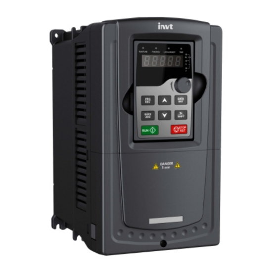
GD310-UL series VFD Product Overview 3 Product Overview 3.1 What this chapter contains The chapter briefly describes the operation principle, product characteristics, layout, name plate and type designation information. 3.2 Basic principles Goodrive310-UL series VFDs are wall or flange mountable devices for controlling asynchronous AC induction motors and permanent magnet synchronous motors. -
Page 16: Product Specification
GD310-UL series VFD Product Overview DC reactor Figure 3-3 Simplified main circuit diagram (VFDs of 575V) Note: 1. The VFDs of 220V (18.5–55kW) and 460V (G-type≥37kW, P-type≥45kW) supports external DC reactors and external braking units, but it is necessary to remove the copper tag between P1 and (+) before connecting. - Page 17 GD310-UL series VFD Product Overview Function Specification Speed control accuracy ±0.2% (SVC) Speed fluctuation ± 0.3% (SVC) Torque response <20ms (SVC) Torque control accuracy 10% (SVC) Asynchronous motor: 0.25Hz/150% (SVC) Starting torque Synchronous motor: 2.5 Hz/150% (SVC) G type: 150% of rated current: 1 minute 180% of rated current: 10 seconds 200% of rated current: 1 second Overload capability...
-
Page 18: Name Plate
6kV. 3.4 Name plate Model: GD310-022G-4-UL E364851 Power(Output): 22kW Input: AC 3PH 380V-480V 56A 47Hz-63Hz Output: AC 3PH 0V-Uinput 45A 0Hz-400Hz S/N: Made in China Shenzhen INVT Electric Co.,Ltd Figure 3-4 Name plate -10-... -
Page 19: Type Designation Key
GD310-UL series VFD Product Overview 3.5 Type designation key The type designation contains information on the VFD. The user can find the type designation on the type designation label attached to the VFD or the simple name plate. GD310 - 022G - 4 - UL ①... -
Page 20: The Vfds Of Ac 3Ph 380V-480V
GD310-UL series VFD Product Overview Note: The input current of VFDs 0.75–55kW is detected when the input voltage is 220V and there are no DC reactors and input/output reactors. The rated output current is defined when the output voltage is 220V. ... - Page 21 GD310-UL series VFD Product Overview Rated output power Rated input current Rated output current Model (kW) GD310-7R5P-4-UL 18.5 GD310-011P-4-UL GD310-015P-4-UL GD310-018P-4-UL 18.5 GD310-022P-4-UL GD310-030P-4-UL GD310-037P-4-UL GD310-045P-4-UL GD310-055P-4-UL GD310-075P-4-UL GD310-090P-4-UL GD310-110P-4-UL GD310-132P-4-UL GD310-160P-4-UL GD310-185P-4-UL GD310-200P-4-UL GD310-220P-4-UL GD310-250P-4-UL GD310-280P-4-UL GD310-315P-4-UL GD310-350P-4-UL GD310-400P-4-UL GD310-500P-4-UL Note: ...
-
Page 22: The Vfds Of Ac 3Ph 520V-600V
GD310-UL series VFD Product Overview 3.6.3 The VFDs of AC 3PH 520V-600V Rated output power Rated input current Rated output current Model (kW) GD310-018G-6-UL 18.5 GD310-022G-6-UL GD310-030G-6-UL GD310-037G-6-UL GD310-045G-6-UL GD310-055G-6-UL GD310-075G-6-UL GD310-090G-6-UL GD310-110G-6-UL Note: The input current of VFDs 18.5–110kW is detected when the input voltage is 575V and there is no DC reactors and input/output reactors. - Page 23 GD310-UL series VFD Product Overview Serial No. Name Description Keypad port Connect the keypad Upper cover Protect the internal parts and components Keypad See Keypad operation procedure for detailed information See Maintenance and hardware diagnostics for detailed Cooling fan information Wiring port Connect to the control board and the drive board Name plate...
-
Page 24: Installation Guidelines
GD310-UL series VFD Installation guidelines 4 Installation guidelines 4.1 What this chapter contains The chapter describes the mechanical installation and electric installation. Only qualified electricians are allowed to carry out what described in this chapter. Please operate as the instructions in Safety Precautions. Ignoring these may cause physical injury or death or damage to the devices. -
Page 25: Installation Direction
<1000m When the installation site altitude exceeds 1000m, derate 1% for every increase Altitude of 100m; when the installation site altitude exceeds 3000m, consult the local INVT dealer or office. ≤ 5.88m/s Vibration (0.6g) -
Page 26: Installation Manner
GD310-UL series VFD Installation guidelines 4.2.3 Installation manner The VFD can be installed in three different ways, depending on the frame size: a) Wall mounting (for the VFDs of 220V ≤55kW; 460V G-type≤200kW, P-type≤220kW and 575V) b) Flange mounting (for the VFDs of 220V ≤55kW; 460V G-type≤200kW, P-type≤220kW and 575V) c) Floor mounting (for the VFDs of 460V G-type 220–500kW, P-type 250–500kW) Figure 4-2 Installation manner (1) Mark the hole location. -
Page 27: Single Installation
GD310-UL series VFD Installation guidelines 4.2.4 Single installation Warm air Cold air Figure 4-3 Single installation Note: The minimum space of B and C is 100mm. 4.2.5 Multiple installations Parallel installation Warm air Cold air Figure 4-4 Parallel installation Note: ... -
Page 28: Vertical Installation
GD310-UL series VFD Installation guidelines 4.2.6 Vertical installation Wind board Wind board Figure 4-5 Vertical installation Note: Windscreen should be installed in vertical installation for avoiding mutual impact and insufficient cooling. -20-... -
Page 29: Slanting Installation
GD310-UL series VFD Installation guidelines 4.2.7 Slanting installation Figure 4-6 Slanting installation Note: Ensure the separation of the wind input and output channels in slanting installation for avoiding mutual impact. -21-... -
Page 30: Standard Wiring
GD310-UL series VFD Installation guidelines 4.3 Standard wiring 4.3.1 Connection diagram of main circuit Connection diagram of main circuit for the VFDs of AC 3PH 380V–480V Braking resistor Output reactor Input 3-PH power supply Output reactor filter Input 50/60Hz filter Fuse Figure 4-7 Connection diagram of main circuit for the VFD of 220V ≤15kW;... -
Page 31: Terminals Figure Of Main Circuit
GD310-UL series VFD Installation guidelines Note: The fuse, DC reactor, braking unit, braking resistor, input reactor, input filter, output reactor, output filter are optional parts. Please refer to Peripheral Optional Parts for detailed information. P1 and (+) are short circuited in factory, if need to connect with the DC rector, please remove the jumper between P1 and (+). - Page 32 GD310-UL series VFD Installation guidelines Figure 4-13 Terminals of main circuit for the VFDs of 220V 7.5kW and 460V G-type 15–18.5kW, P-type 18.5–22kW Figure 4-14 Terminals of main circuit for the VFDs of 220V 11–15kW and 460V G-type 22–30kW, P-type 30–37kW Figure 4-15 Terminals of main circuit for the VFDs of 220V 18.5–30kW and 460V G-type 37–55kW, P-type 45–55kW and 575V 18.5–37kW -24-...
- Page 33 GD310-UL series VFD Installation guidelines Figure 4-16 Terminals of main circuit for the VFDs of 220V 37–55kW 460V G-type 75–110kW, P-type 75–110kW and 575V 45–110kW POWER Figure 4-17 erminals of main circuit for the VFDs of 460V G-type 132–200kW, P-type 132–220kW Figure 4-18 erminals of main circuit for the VFDs of 460V G-type 220–315kW, P-type 250–350kW...
- Page 34 GD310-UL series VFD Installation guidelines Figure 4-19 erminals of main circuit for the VFDs of 460V G-type 350–500kW, P-type 400–500kW 220V≥18.5kW 220V≤15kW 460V G-type≥37kW Terminal 460V G-type≤30kW Function 460V P-type≥45kW 460V P-type≤37kW 575V 3-phase AC input terminals which are R, S, T Power input of the main circuit generally connected...
-
Page 35: Wiring Of Terminals In Main Circuit
GD310-UL series VFD Installation guidelines Note: Do not use an asymmetrically constructed motor cable. If there is a symmetrically constructed grounding conductor in the motor cable in addition to the conductive shield, connect the grounding conductor to the grounding terminal at the VFD and motor ends. ... -
Page 36: Wiring Diagram Of Control Circuit
GD310-UL series VFD Installation guidelines 4.3.4 Wiring diagram of control circuit Profibus Multi-function input terminal 1 External Standard extension DB9 plug card Multi-function input terminal 2 (optional) Multi-function input terminal 3 Multi-function input terminal 4 0–10V/0–20mA Multi-function input terminal 5 Multi-function input terminal 6 Multi-function input terminal 7 0–10V/0–20mA... - Page 37 GD310-UL series VFD Installation guidelines Terminal Description name +10V Local power supply +10V 1. Input range: AI1/AI2 voltage and current can be chosen: 0–10V/0–20mA; AI1 can be shifted by J3; AI2 can be shifted by J4 AI3: -10V–+10V 2. Input impedance: voltage input: 20kΩ; current input: 500Ω 3.
-
Page 38: Input /Output Signal Connection Figure
GD310-UL series VFD Installation guidelines 4.3.6 Input /Output signal connection figure Please use U-shaped jumper to set NPN mode or PNP mode and the internal or external power supply. The default setting is NPN internal mode. Torsional moment :35 ibf in U-shaped jumper U-shaped jumper between... -
Page 39: Layout Protection
GD310-UL series VFD Installation guidelines 4.4 Layout protection 4.4.1 Protecting the VFD and input power cable in short-circuit situations Protect the VFD and input power cable in short circuit situations and against thermal overload. Arrange the protection according to the following guidelines. Input cables Fuse Figure 4-26 Fuse configuration... -
Page 40: Keypad Operation Procedure
GD310-UL series VFD Keypad operation procedure 5 Keypad operation procedure 5.1 What this chapter contains This chapter contains following operation: Buttons, indicators and the screen as well as the methods to inspect, modify and set function codes by keypad 5.2 Keypad The keypad is used to control Goodrive310-UL series VFDs, read the state data and adjust parameters. - Page 41 GD310-UL series VFD Keypad operation procedure Name Description FED/REV LED LED off means the VFD is in the forward rotation FWD/REV state; LED on means the VFD is in the reverse rotation state LED for keypad operation, terminals operation and remote communication control LED off means that the VFD is in the keypad LOCAL/REMOT...
-
Page 42: Keypad Displaying
GD310-UL series VFD Keypad operation procedure Name Description Programming Enter or escape from the first level menu and remove the parameter quickly Enter the menu step-by-step DATA Entry key Confirm parameters UP key Increase data or function code progressively DOWN key Decrease data or function code progressively Move right to select the displaying parameter Right-shift circularly in stopping and running mode. -
Page 43: Displayed State Of Running Parameters
GD310-UL series VFD Keypad operation procedure 5.3.2 Displayed state of running parameters After the VFD receives valid running commands, the VFD will enter into the running state and the keypad will display the running parameters. RUN/TUNE LED on the keypad is on, while the FWD/REV is determined by the current running direction which is shown as figure 5-2. -
Page 44: How To Modify The Function Codes Of The Vfd
GD310-UL series VFD Keypad operation procedure 5.4.1 How to modify the function codes of the VFD The VFD has three levels menu, which are: 1. Group number of function code (first-level menu) 2. Tab of function code (second-level menu) 3. Set value of function code (third-level menu) Remarks: Press both the PRG/ESC and the DATA/ENT can return to the second-level menu from the third-level menu. -
Page 45: How To Watch The Vfd State Through Function Codes
GD310-UL series VFD Keypad operation procedure The unit is blinking All digits are blinking The unit is blinking DATA DATA DATA The unit is blinking The unit is blinking The unit is blinking Note: When setting, can be used to shift and adjust SHIFT Figure 5-4 Sketch map of password setting 5.4.3 How to watch the VFD state through function codes... -
Page 46: Function Parameter
GD310-UL series VFD Function parameter 6 Function parameter 6.1 What this chapter contains This chapter lists and describes the function parameters. 6.2 Function parameter list The function parameters of Goodrive310-UL series VFDs have been divided into 30 groups (P00–P29) according to the function, of which P18–P28 are reserved. Each function group contains certain function codes applying 3-level menus. -
Page 47: P00 Group Basic Function Group
GD310-UL series VFD Function parameter the system. For the factory setting parameter zone, it needs correct factory password (remind that the users cannot modify the factory parameters by themselves, otherwise, if the parameter setting is incorrect, damage to the VFD may occur). If the password protection is unlocked, the user can modify the password freely and the VFD will work as the last setting one. - Page 48 GD310-UL series VFD Function parameter Function Default Name Description Modify code value 1: Terminal running command channel (“LOCAL/REMOT” flickering) Carry out the running command control by the forward rotation, reverse rotation and forward jogging and reverse jogging of the multi-function terminals 2: Communication running command channel (“LOCAL/REMOT”...
- Page 49 GD310-UL series VFD Function parameter Function Default Name Description Modify code value keypad) to modify the frequency by the keypad. 1: AI1 2: AI2 3: AI3 Set the frequency by analog input terminals. Goodrive310-UL series VFDs provide 3 ways analog input terminals as the standard configuration, of which AI1/AI2 are the voltage/current option (0–10V/0–20mA) which can be shifted by jumpers;...
- Page 50 GD310-UL series VFD Function parameter Function Default Name Description Modify code value 6: Multi-step speed running setting The VFD runs at multi-step speed mode when P00.06=6 or P00.07=6. Set P05 to select the current running stage, and set P10 to select the current running frequency.
- Page 51 GD310-UL series VFD Function parameter Function Default Name Description Modify code value command + B frequency command 3: A-B, the current frequency setting is A frequency command - B frequency command 4: Max (A, B): The bigger one between A frequency command and B frequency is the set frequency.
- Page 52 GD310-UL series VFD Function parameter Function Default Name Description Modify code value 2: Forbid to run in reverse direction: It can be used in some special cases if the reverse running is disabled. Carrier Electro magnetic Noise and leakage Heating frequency noise current...
- Page 53 GD310-UL series VFD Function parameter Function Default Name Description Modify code value When the frequency used exceeds the default carrier frequency, the VFD needs to derate according to the detailed information of Appendix B. Setting range: 1.0–15.0kHz 0: No operation 1: Rotating autotuning Comprehensive motor parameter autotune It is recommended to use Rotating autotuning when...
-
Page 54: P01 Group Start-Up And Stop Control
GD310-UL series VFD Function parameter P01 Group Start-up and stop control Function Default Name Description Modify code value 0: Start-up directly: start from the starting frequency P01.01 1: Start-up after DC braking: start the motor from the starting frequency after DC braking (set the parameter P01.03 and P01.04). - Page 55 GD310-UL series VFD Function parameter Function Default Name Description Modify code value 0, the DC braking is invalid. The stronger the braking current, the bigger the The braking braking power. The DC braking current before starting means the percentage of the rated output ◎...
- Page 56 GD310-UL series VFD Function parameter Function Default Name Description Modify code value The braking time of stop braking: the retention time of DC brake. If the time is 0, the DC brake is invalid. The VFD will stop at the set deceleration time. P01.09 Constant speed DEC...
- Page 57 GD310-UL series VFD Function parameter Function Default Name Description Modify code value If set P01.16 to 1, the feedback frequency is less than or equal to P01.15 and detect in the set time of P01.17, the VFD will stop; otherwise the VFD will stop after the set time of P01.17.
- Page 58 GD310-UL series VFD Function parameter Function Default Name Description Modify code value This function code determines the hibernation delay time. When the running frequency of the VFD is lower than the lower limit one, the VFD will pause to stand by. When the set frequency is above the lower limit one again and it lasts for the time set by P01.20, the VFD will run automatically.
-
Page 59: P02 Group Motor 1
GD310-UL series VFD Function parameter Function Default Name Description Modify code value stand-by state and wait for the delay time set by P01.23 Setting range: 0.0–60.0s Delay time of ○ P01.24 Setting range: 0.0–100.0 s 0.0s the stop speed Select the output mode at 0Hz. 0Hz output 0: Output without voltage ○... - Page 60 GD310-UL series VFD Function parameter Function Default Name Description Modify code value Magnetic saturation ◎ coefficient 1 P02.11 0.0–100.0% 80.0% for the iron core of AM 1 Magnetic saturation ◎ coefficient 2 P02.12 0.0–100.0% 68.0% for the iron core of AM 1 Magnetic saturation ◎...
- Page 61 GD310-UL series VFD Function parameter Function Default Name Description Modify code value When P00.15=2, the set value of P02.23 cannot be updated by autotuning, please count according to the following method. The counter-electromotive force constant can be counted according to the parameters on the name plate of the motor.
-
Page 62: P03 Group Vector Control
GD310-UL series VFD Function parameter Function Default Name Description Modify code value coefficient coefficient. So, the bigger the value of K is, the smaller the value of M is. When M =116%, the fault will be reported after 1 hour, when M =200%, the fault will be reported after 1 minute, when M>=400%, the fault will be reported instantly. - Page 63 GD310-UL series VFD Function parameter Function Default Name Description Modify code value Setting the proportional coefficient and integral time of the adjustor can change the dynamic response performance of vector control speed loop. Increasing the proportional gain and decreasing the integral time can speed up the dynamic response of the speed loop.
- Page 64 GD310-UL series VFD Function parameter Function Default Name Description Modify code value This parameter is used to enable the torque control mode, and set the torque. 0: Torque control is invalid 1: Keypad setting torque (P03.12) 2: Analog AI1 setting torque 3: Analog AI2 setting torque 4: Analog AI3 setting torque Torque setting...
- Page 65 GD310-UL series VFD Function parameter Function Default Name Description Modify code value Keypad setting frequency) for upper ○ frequency of P03.17 60.00Hz reverse rotation Upper This function code is used to select the electromotion ○ P03.18 electromotion and braking torque upper-limit setting source torque source selection.
-
Page 66: P04 Group Svpwm Control
GD310-UL series VFD Function parameter Function Default Name Description Modify code value weakening control coefficient. The bigger the weakening control coefficient is, the steeper the weak curve is. Setting range of P03.22: 0.1–2.0 Setting range of P03.23: 10%–100% P03.24 set the max Voltage of the VFD, which is Max voltage ◎... - Page 67 GD310-UL series VFD Function parameter Function Default Name Description Modify code value Curves 2–4 apply to the torque loads such as fans and water pumps. Users can adjust according to the features loads achieve best energy-consuming effect. 5: Customized V/F (V/F separation); in this mode, V and F can be separated from adjusted through the frequency given channel set by P00.06 or voltage given channel set by P04.27 to change the curve...
- Page 68 GD310-UL series VFD Function parameter Function Default Name Description Modify code value V/F frequency Output voltage ○ P04.03 0.00Hz 100.0% 1 of motor 1 V/F voltage 1 ○ P04.04 00.0% of motor 1 Output V/F frequency frequency ○ P04.05 00.00Hz f2 f3 2 of motor 1 When P04.00 =1, the user can set V//F curve...
- Page 69 GD310-UL series VFD Function parameter Function Default Name Description Modify code value at low occur to the motor at some frequency, especially the frequency of motor with big power. The motor cannot run stably or motor 1 overcurrent may occur. These phenomena can be Vibration canceled by adjusting this parameter.
- Page 70 GD310-UL series VFD Function parameter Function Default Name Description Modify code value Vibration canceled by adjusting this parameter. control factor Setting range of P04.23: 0–100 ○ at high P04.24 Setting range of P04.24: 0–100 frequency of Setting range of P04.25: 0.00Hz–P00.03 (max motor 2 frequency) Vibration...
-
Page 71: P05 Group Input Terminals
GD310-UL series VFD Function parameter Function Default Name Description Modify code value Maximum Set the upper and low limit of the output voltage. ◎ P04.31 100.0% output voltage Setting range of P04.31: P04.32–100.0% (the rated voltage of the motor) Setting range of P04.32: 0.0%– P04.31 (the rated voltage of the motor) Minimum Vmax... - Page 72 GD310-UL series VFD Function parameter Function Default Name Description Modify code value 9: External fault input S4 terminals 10: Increasing frequency setting (UP) ◎ P05.04 function 11: Decreasing frequency setting (DOWN) selection 12: Frequency setting clear S5 terminals 13: Shift between A setting and B setting ◎...
- Page 73 GD310-UL series VFD Function parameter Function Default Name Description Modify code value Set the bit to 0, the input terminal is anode. the input Set the bit to 1, the input terminal is cathode. terminals BIT0 BIT1 BIT2 BIT3 BIT4 BIT5 BIT6 BIT7...
- Page 74 GD310-UL series VFD Function parameter Function Default Name Description Modify code value Running FWD REV command Stopping Forward running Stopping Reverse running 2: 3-wire control 1; Sin is the enabling terminal on this mode, and the running command is caused by FWD and the direction is controlled by REV.
- Page 75 GD310-UL series VFD Function parameter Function Default Name Description Modify code value Direction Forward OFF→ON Reverse OFF→ Forward Reverse Decelerate ON→OFF to stop Note: for the 2-wire running mode, when FWD/REV terminal is valid, the VFD stop because of the stopping command from other sources, even the control terminal FWD/REV keeps valid;...
- Page 76 GD310-UL series VFD Function parameter Function Default Name Description Modify code value Switch-off ○ P05.21 delay of S4 0.000s terminal Switch-on ○ P05.22 delay of S5 0.000s terminal Switch-off ○ P05.23 delay of S5 0.000s terminal Switch-on ○ delay of S6 P05.24 0.000s terminal...
- Page 77 GD310-UL series VFD Function parameter Function Default Name Description Modify code value When the analog input is the current input, the corresponding voltage of 0–20mA is 0–10V. Upper limit of ○ P05.34 10.00V In different cases, the corresponding rated value of 100.0% is different.
-
Page 78: P06 Group Output Terminals
GD310-UL series VFD Function parameter Function Default Name Description Modify code value the upper limit Setting range of P05.45: -100.0%–100.0% of AI3 Setting range of P05.46: P05.44–10.00V AI3 input filter Setting range of P05.47: -100.0%–100.0% ○ P05.48 0.100s time Setting range of P05.48: 0.000s–10.000s The function selection when HDI terminals is high-speed pulse input high-speed... - Page 79 GD310-UL series VFD Function parameter Function Default Name Description Modify code value 1: Open collector pole output. See P06.02 for detailed information of the related functions. 0: Invalid ○ P06.01 Y1 output 1: In operation ○ P06.02 HDO output 2: Forward rotation operation Relay RO1 ○...
- Page 80 GD310-UL series VFD Function parameter Function Default Name Description Modify code value Y1 switch-on ○ P06.06 0.000s delay time Y1 switch-off ○ P06.07 0.000s delay time The function code defines the corresponding delay time of the electrical level change during the ○...
- Page 81 GD310-UL series VFD Function parameter Function Default Name Description Modify code value 12: AI3 input value 13: High speed pulse HDI input value 14: MODBUS communication set value 1 15: MODBUS communication set value 2 16: PROFIBUS/CANopen communication set value 1 17: PROFIBUS/CANopen communication set value 2 18: Ethernet communication set value 1 19: Ethernet communication set value 2...
-
Page 82: P07 Group Human-Machine Interface
GD310-UL series VFD Function parameter Function Default Name Description Modify code value Lower output Setting range of P06.25: 0.00V–10.00V ○ P06.27 0.0% limit of HDO Setting range of P06.26: 0.000s–10.000s Setting range of P06.27: -100.0%–P06.29 Corresponding ○ Setting range of P06.28: 0.00–50.00kHz P06.28 HDO output of 0.00kHz... - Page 83 GD310-UL series VFD Function parameter Function Default Name Description Modify code value 1: Upload the local function parameter to the keypad 2: Download the keypad function parameter to local address (including the motor parameters) 3: Download the keypad function parameter to local address (excluding the motor parameter of P02 and P12 group) 4: Download the keypad function parameters to local...
- Page 84 GD310-UL series VFD Function parameter Function Default Name Description Modify code value →communication control QUICK/JOG 1: Keypad control←→terminals control commands 2: Keypad control←→communication control 3: Terminals control←→communication control STOP/RST is valid for stop function. STOP/RST is valid in any state for the fault reset. STOP/RST 0: Only valid for the keypad control ○...
- Page 85 GD310-UL series VFD Function parameter Function Default Name Description Modify code value 0x0000–0xFFFF BIT0: set frequency (Hz on, frequency flickering slowly) BIT1: bus voltage (V on) BIT2: input terminals state BIT3: output terminals state BIT4: PID reference (% flickering) BIT5: PID feedback value (% on) Parameters for BIT6: torque reference (% on) ○...
- Page 86 GD310-UL series VFD Function parameter Function Default Name Description Modify code value High bit of Display the power used by the VFD. ● P07.15 power power consumption consumption =P07.15*1000+P07.16 Low bit of Setting range of P07.15: 0–65535 kWh (*1000) ● P07.16 power Setting range of P07.16: 0.0–999.9 kWh...
- Page 87 GD310-UL series VFD Function parameter Function Default Name Description Modify code value 14: Phase loss on output side (SPO) 15: Rectifier module overheat (OH1) 16: Inverter module overheat (OH2) 17: External fault (EF) 18: 485 communication fault (CE) 19: Current detection fault (ItE) 20: Motor autotuning fault (tE) 21: EEPROM operation fault (EEP) 22: PID feedback offline fault (PIDE)
-
Page 88: P08 Group Enhanced Function
GD310-UL series VFD Function parameter Function Default Name Description Modify code value ● P07.49 Running frequency at the last but one fault 0.00Hz ● P07.50 Output voltage at the last but one faults 0.00Hz ● P07.51 Output current at the last but one faults ●... - Page 89 GD310-UL series VFD Function parameter Function Default Name Description Modify code value Jumping Set frequency f ○ ½* jump frequency P08.12 frequency 0.00Hz Jump amplitude 3 frequency 3 ½* jump frequency range 2 amplitude 3 Jumping ½* jump frequency Jump ○...
- Page 90 GD310-UL series VFD Function parameter Function Default Name Description Modify code value Setting range of P08.15: 0.0–100.0% (relative to the set frequency) Setting range of P08.16: 0.0–50.0% (relative to the traverse range) Setting range of P08.17: 0.1–3600.0s Setting range of P08.18: 0.1–3600.0s Setting length The function codes of setting length, actual length ○...
- Page 91 GD310-UL series VFD Function parameter Function Default Name Description Modify code value Output frequency The set Detecting frequency range RO1, RO2 Setting range of P08.25: P08.26–65535 Setting range of P08.26: 0–P08.25 Pre-set running time of the VFD. When the accumulative running time achieves the set time, the Set running ○...
- Page 92 GD310-UL series VFD Function parameter Function Default Name Description Modify code value LED tens: shifting enabling in operation 0: Disabled 1: Enabled 0x00–0x14 FDT1 When the output frequency exceeds the electrical level corresponding frequency of FDT electrical level, the ○ P08.32 60.00Hz detection...
- Page 93 GD310-UL series VFD Function parameter Function Default Name Description Modify code value Output frequency The set Detecting frequency range RO1, RO2 The setting range: 0.00Hz–P00.03 (the max frequency) This parameter is used to control the internal braking pipe inside the VFD. Energy ○...
- Page 94 GD310-UL series VFD Function parameter Function Default Name Description Modify code value LED ones 0: Invalid Overmodulatio 1: Valid ◎ P08.41 n selection LED tens (for factory commissioning) 0: Light overmodulation; in zone 1 1: Heavy overmodulation; in zone 2 0x000–0x1223 LED ones: frequency enable selection 0: Both ∧...
- Page 95 GD310-UL series VFD Function parameter Function Default Name Description Modify code value 2: When the multi-step are priority, it is invalid to the multi-step LED hundreds: action selection when stop 0: Setting valid 1: Valid in the running, clear after stop 2: Valid in the running, clear after receiving the stop commands UP terminals...
-
Page 96: P09 Group Pid Control
GD310-UL series VFD Function parameter Function Default Name Description Modify code value motor during braking can be converted into heat energy by increasing the magnetic flux. monitors state motor continuously even during the magnetic flux period. So the magnetic flux can be used in the motor stop, as well as to change the rotation speed of the motor. - Page 97 GD310-UL series VFD Function parameter Function Default Name Description Modify code value The setting target of procedure PID is a relative one, 100% of the setting equals to 100% of the response of the controlled system. The system is calculated according to the relative value (0–100.0%).
- Page 98 GD310-UL series VFD Function parameter Function Default Name Description Modify code value range of PID adjustor is the max frequency (ignoring integral and differential function). The setting range: 0.00–100.00 This parameter determines the speed of PID adjustor to carry out integral adjustment on the deviation of PID feedback and reference.
- Page 99 GD310-UL series VFD Function parameter Function Default Name Description Modify code value Feedbackvalue Bias limit Reference value Output frequency Setting range: 0.0–100.0% Output upper This parameter is used to set the upper and lower ○ P09.09 100.0% limit of PID limit of the PID adjustor output.
-
Page 100: P10 Group Simple Plc And Multi-Step Speed Control
GD310-UL series VFD Function parameter Function Default Name Description Modify code value impact of continuous working and the integration will change with the trend. 1: Stop integral adjustment when the frequency achieves the upper and low limit. If the integration keeps stable, and the trend between the reference and the feedback changes, the integration will change with the trend quickly. - Page 101 GD310-UL series VFD Function parameter Function Default Name Description Modify code value 0: Power loss without memory Simple PLC ○ 1: Power loss with memory; PLC record the running P10.01 memory stage and frequency when power loss. Multi-step The frequency setting range of stage 0–15: ○...
- Page 102 GD310-UL series VFD Function parameter Function Default Name Description Modify code value Multi-step When terminal 1, terminal 2, terminal 3, terminal ○ P10.20 0.0% speed 9 4=OFF, the frequency input manner is selected via Running time code P00.06 or P00.07. When terminal 1, terminal 2, ○...
-
Page 103: P11 Group Protective Parameters
GD310-UL series VFD Function parameter Function Default Name Description Modify code value BIT1 BIT0 BIT3 BIT2 BIT5 BIT4 BIT7 BIT6 P10.35 BIT9 BIT8 BIT11 BIT10 BIT13 BIT12 BIT15 BIT14 After users select the corresponding ACC/DEC time, the combining 16 binary bit can be changed into hexadecimal bit, and then set the corresponding function codes. - Page 104 GD310-UL series VFD Function parameter Function Default Name Description Modify code value 0: Disable output phase loss protection 1: Enable output phase loss protection Hundreds: 0: Disable hardware input phase loss protection 1: Enable hardware input phase loss protection Frequency-de creasing at 0: Enable ○...
- Page 105 GD310-UL series VFD Function parameter Function Default Name Description Modify code value The actual increasing ratio of motor speed is lower than the ratio of output frequency because of the big load during ACC running. It is necessary to take measures to avoid overcurrent fault and VFD tripping.
- Page 106 GD310-UL series VFD Function parameter Function Default Name Description Modify code value Output current Overload Overload pre-alarm point ○ P11.09 pre-alarm 150% detection Pre-alarm time Pre-alarm time RO1, RO2 Setting range of P11.08: Enable and define the overload pre-alarm of the VFD or the motor.
-
Page 107: P12 Group Motor 2
GD310-UL series VFD Function parameter Function Default Name Description Modify code value Select the action of fault output terminals on undervoltage and fault reset. 0x00–0x11 Output LED ones: ○ P11.13 terminal action 0: Action under fault undervoltage 0x00 during fault 1: No action under fault undervoltage LED tens: 0: Action during the automatic reset... - Page 108 GD310-UL series VFD Function parameter Function Default Name Description Modify code value controlling performance, set Rated the P12.01–P12.05 frequency of 0.01Hz–P00.03 ◎ P12.02 60.00Hz according to the name plate asynchronous (the max frequency) of the asynchronous motor. motor 2 Goodrive310-UL series Rated speed VFDs provide the function of Depend...
- Page 109 GD310-UL series VFD Function parameter Function Default Name Description Modify code value Non-load current of Depend ○ P12.10 0.1–6553.5A asynchronous on model motor 2 Magnetic saturation ◎ coefficient 1 P12.11 0.0–100.0% 80.0% for the iron core of AM2 Magnetic saturation ◎...
- Page 110 GD310-UL series VFD Function parameter Function Default Name Description Modify code value Rated current In order to ensure the controlling performance, Depend ◎ P12.19 0.8–6000.0A synchronous please configure the motor on model motor 2 according to the standard principles, if the gap between the motor and the standard one is huge, the Stator resistor...
- Page 111 GD310-UL series VFD Function parameter Function Default Name Description Modify code value counter-electromotive force constant Ke, then: *2π)/ 60 E=(Ke*n 2. If the name plate designate the counter-electromotive force constant E’(V/1000r/min), then: E=E’*n /1000 3. If the name plate does not designate the above parameters, then: E=P/√3*I...
-
Page 112: P13 Group Synchronous Motor Control
GD310-UL series VFD Function parameter Function Default Name Description Modify code value of M is. When M =116%, the fault will be reported after 1 hour, when M =200%, the fault will be reported after 1 minute, when M>=400%, the fault will be reported instantly. - Page 113 GD310-UL series VFD Function parameter Function Default Name Description Modify code value Source current is directional current of the magnetic pole position. Source current 2 is valid under the Source current ○ P13.03 frequency point of current shifting. There is no need 10.0% to modify the value generally.
-
Page 114: P14 Group Serial Communication
GD310-UL series VFD Function parameter Function Default Name Description Modify code value when stopping to the rated output current of the VFD) Setting range of P13.14: 0.00–50.00s Setting range of P13.15: 0.00–50.00s P14 Group Serial communication Function Default Name Description Modify code value... - Page 115 GD310-UL series VFD Function parameter Function Default Name Description Modify code value 2: Odd check (O,8,1) for RTU 3: No check (N,8,2) for RTU 4: Even check (E,8,2) for RTU 5: Odd check (O,8,2) for RTU 0–200ms The interval time when the drive receives the data and sent it to the upper monitor.
-
Page 116: P15 Group Profibus/Canopen Function
GD310-UL series VFD Function parameter P15 Group PROFIBUS/CANopen function Function Default Name Description Modify code value 0: PROFIBUS ◎ P15.00 Module type 1: CANopen Select communication protocol 0–127 This function code is used to designate the address of the VFD. Module ◎... - Page 117 GD310-UL series VFD Function parameter Function Default Name Description Modify code value corresponds to 100.0%) 13: AO output set value 2 (-1000–1000, 1000 corresponds to 100.0%) 14–20: Reserved P15.13 PZD2 sending 0: Invalid ○ 1: Running frequency (*100, Hz) ○ P15.14 PZD3 sending 2: Setting frequency (*100, Hz) ○...
-
Page 118: P16 Group Ethernet Function
GD310-UL series VFD Function parameter Function Default Name Description Modify code value 0.0 (invalid), 0.1–60.0s When this function code is set as 0.0, this function is Fault time of invalid. CANopen When the function code is set as nonzero value, if P15.26 0.0s communica... -
Page 119: P17 Group Monitoring Function
GD310-UL series VFD Function parameter Function Default Name Description Modify code value ◎ P16.09 Gateway 1 ◎ P16.10 Gateway 2 0–255 ◎ Set the gateway of Ethernet communication P16.11 Gateway 3 ◎ P16.12 Gateway 4 P17 Group Monitoring function Function Default Name Description... - Page 120 GD310-UL series VFD Function parameter Function Default Name Description Modify code value Range: 0000–01FF Display current Switch output terminals state of the Digital output ● P17.13 BIT3 BIT2 BIT1 BIT0 terminals state Range: 0000–000F Display the adjustment through the keypad of the Digital ●...
- Page 121 GD310-UL series VFD Function parameter Function Default Name Description Modify code value The percentage of the rated torque of the relative ASR controller ● motor, display ASR controller output P17.28 0.0% output Range: -300.0%–300.0% (rated motor current) Magnetic pole Display synchronous motor Magnetic pole angle ●...
-
Page 122: Basic Operation Instruction
GD310-UL series VFD Basic operation instruction 7 Basic operation instruction 7.1 What this chapter contains This chapter describes the internal function mode of the VFD in details. Check all terminals are connected properly and tightly. Check that the power of the motor corresponds to that of the VFD. 7.2 First powering on Check before powering on Please check according to the installation list in chapter two. - Page 123 GD310-UL series VFD Basic operation instruction Start Power on after right wiring Restore to the factory parameters(P00.18=1 ) Motor type selection (P02.00 ) Asynchronous motor Synchronous motor Set P02.01~P02.05 Set P02.15~P02.19 Press QUICK / JOG to jog If the rotation direction is wrong, power off to change the wires and repower on Set autotuning Set P00.15=2...
- Page 124 GD310-UL series VFD Basic operation instruction Current running Multi-function Multi-function Multi-function terminal 38 command channel terminal 36 terminal 37 Switch to to P00.01 Switch to keypad Switch to to terminal communication Keypad running Terminal running Communication running command channel command channel command channel Terminal running Keypad running...
- Page 125 GD310-UL series VFD Basic operation instruction Function Default Name Description code value Rated power of Depend on P02.01 0.1–3000.0kW asynchronous motor 1 model Rated frequency of P02.02 0.01Hz–P00.03 (the max frequency) 60.00Hz asynchronous motor 1 Rated speed of Depend on P02.03 1–36000rpm asynchronous motor 1...
-
Page 126: Vector Control
GD310-UL series VFD Basic operation instruction Function Default Name Description code value 0: No function 1: Jogging 2: Shift the display state by the shifting key 3: Shift between forward rotations and reverse QUICK/JOG function rotations P07.02 selection 4: Clear UP/DOWN settings 5: Coast to stop 6: Shift the given manner of running commands 7: Quick commissioning mode (committee... - Page 127 GD310-UL series VFD Basic operation instruction Rectifier bridge Calculation Park Exciting current Transfo Converting Pulse rmation bridge Calculation Torque current Position observing Voltage detection Flux observing Park Clark Current Transfo Transfo detection rmation rmation Motor Function Default Name Description code value 0: SVC mode 0 (apply to AM and SM) P00.00...
- Page 128 GD310-UL series VFD Basic operation instruction Function Default Name Description code value P03.06 Speed loop output filter 0–8 (corresponds to 0–2 /10ms) Compensation P03.07 coefficient of 50%–200% 100% electromotion slip Compensation P03.08 coefficient of braking 50%–200% 100% slip Current loop percentage P03.09 0–65535 1000...
- Page 129 GD310-UL series VFD Basic operation instruction Function Default Name Description code value upper-limit frequency 7: PROFIBUS/CANopen communication setting upper-limit frequency 8: Ethernet communication setting upper-limit frequency 9: Reserved Note: Setting method 1–9, 100% corresponds to the maximum frequency. Keypad setting for upper frequency of forward P03.16 60.00Hz...
-
Page 130: Svpwm Control
GD310-UL series VFD Basic operation instruction 7.4 SVPWM control The VFDs provide internal SVPWM control which can be used in the cases where it does not need high control accuracy. It is also recommended to use SVPWM control when one VFD drives multiple motors. - Page 131 GD310-UL series VFD Basic operation instruction 1. Torque boost Torque boost function can compensate the performance of low speed torque during SVPWM control. The VFD will adjust the torque boost according to the actual load. Note: The torque boost takes effect only when the frequency is under the cap frequency of the boost. If the torque boost is too big, low frequency vibration or overcurrent fault may occur.
- Page 132 GD310-UL series VFD Basic operation instruction 5. User-defined V/F curve (V/F separation) function P04.28 Keypad Voltage setting Keypad setting voltage Linear V/F curve Multi-dots V/F curve Multi-stage speed 1.3th power of torque V/F curve 1.7th power pf torque V/F curve 2.0th power of torque V/F curve MODBUS Self-defined V/F curve...
- Page 133 GD310-UL series VFD Basic operation instruction Function Default Name Description code value Rated frequency of 0.01Hz–P00.03 (max frequency) 60.00 P02.02 asynchronous motor 1 Rated voltage of Depend on P02.04 0–1200V asynchronous motor 1 model 0: Straight line V/F curve; applying to the constant torque load 1: Multi-dots V/F curve P04.00...
-
Page 134: Torque Control
GD310-UL series VFD Basic operation instruction Function Default Name Description code value P04.18 V/F frequency 2 of motor 2 P04.16– P04.20 0.00Hz P04.19 V/F voltage 2 of motor 2 0.0%–110.0% 0.0% P04.20 V/F frequency 3 of motor 2 P04.18– P02.02 or P04.18– P02.16 0.00Hz P04.21 V/F voltage 3 of motor 2... - Page 135 GD310-UL series VFD Basic operation instruction -127-...
- Page 136 GD310-UL series VFD Basic operation instruction Function Default Name Description code value 0: SVC mode 0 (apply to AM and SM) P00.00 Speed control mode 1: SVC mode 1 (applying to AM) 2: SVM control 0: Torque control is invalid 1: Keypad setting torque (P03.12) 2: Analog AI1 setting torque 3: Analog AI2 setting torque...
-
Page 137: Parameters Of The Motor
GD310-UL series VFD Basic operation instruction Function Default Name Description code value Keypad setting for P03.16 upper frequency of 0.00Hz–P00.03 (the max frequency) 60.00 Hz forward rotation Keypad setting for P03.17 upper frequency of 0.00 Hz–P00.03 (the max frequency) 60.00 Hz reverse rotation Upper electromotion 0: Keypad setting upper-limit frequency (P03.20... - Page 138 GD310-UL series VFD Basic operation instruction The VFDs can drive both asynchronous motors and synchronous motors. And at the same time, they can support two sets of motor parameters which can shift between two motors through multi-function digital input terminal or communication. Start Select command channel...
- Page 139 GD310-UL series VFD Basic operation instruction Ready P00.01=0 P02.00 P02.00=1 P02.00=0 (P02.15~P02.19 ) (P02.01~P02.05 ) P00.15 P00.15=3 P00.15=1 P00.15=2 Press“RUN” to begin autotuning A utotuning Display“- END- ” A utotuning end Note: 1. Set the motor parameters according to the name plate of the motor. 2.
- Page 140 GD310-UL series VFD Basic operation instruction Related parameters list: Function Name Description Default value code 0: Keypad running command 1: Terminal running command channel (“LOCAL/REMOT” P00.01 Run command channel flickering) 2: Communication running command channel (“LOCAL/REMOT” on); 0: No operation 1: Rotating autotuning 2: Static autotuning 1 (autotune P00.15...
- Page 141 GD310-UL series VFD Basic operation instruction Function Name Description Default value code Multi-function digital input P05.01– terminals (S1–S8, HDI) 35: Shift from motor 1 to motor 2 P05.09 function selection LED ones: shifting channel 0: terminal shifting 1: MODBUS communication shifting 2: PROFIBUS/CANopen communication shifting 3: Ethernet communication shifting...
-
Page 142: Start-Up And Stop Control
GD310-UL series VFD Basic operation instruction Function Name Description Default value code Quadrature axis inductance P12.22 0.01–655.35mH Depend on model of SM 2 P12.23 Back EMF constant of SM 2 0–10000 7.7 Start-up and stop control The start-up and stop control of the VFD includes three states: start after the running command during normal powering on, start after the restarting function becomes valid during normal powering on and start after the automatic fault reset. - Page 143 GD310-UL series VFD Basic operation instruction 2. The starting logic figure of starting after the restarting function becomes valid during the normal powering on Running Running Stand by Stoppin Keypad The running state before stopping power off Comm Restart after unicati the power off The retention time of the...
- Page 144 GD310-UL series VFD Basic operation instruction Function Name Description Default value code P00.11 ACC time 1 0.0–3600.0s Depend on model P00.12 DEC time 1 0.0–3600.0s Depend on model 0: Start-up directly 1: Start-up after DC braking P01.00 Start mode 2: Start-up after rotation speed tracking 1 Starting frequency of direct P01.01...
-
Page 145: Frequency Setting
GD310-UL series VFD Basic operation instruction Function Name Description Default value code Action if running 0: Run at the lower-limit frequency P01.19 frequency< lower limit 1: Stop frequency (valid >0) 2: Hibernation Hibernation restore delay P01.20 0.0–3600.0s (valid when P01.19=2) 0.0s time 0: Disable... - Page 146 GD310-UL series VFD Basic operation instruction These two given channels can carry out mutual simple math calculation between each other. And the given channels can be shifted dynamically through set multi-function terminals. There are three assistant given channels: keypad UP/DOWN input, terminals UP/DOWN switch input and digital potentiometer input.
- Page 147 GD310-UL series VFD Basic operation instruction Multi-function terminal Multi-function terminal Multi-function terminal Current given function 14 function 15 function 13 channel Switch from Switch from Switch from A channel to P00.09 combination setting to combination setting to B channel A channel B channel Max (A, B) Min (A, B)
- Page 148 GD310-UL series VFD Basic operation instruction Function Default Name Description code value 7: PID control setting 8: MODBUS communication setting 9: PROFIBUS/CANopen communication setting 10: Ethernet communication setting (reserved) 11: Reserved B frequency command 0: Maximum output frequency P00.08 reference 1: A frequency command 0: A 1: B...
- Page 149 GD310-UL series VFD Basic operation instruction Function Default Name Description code value 0: Setting is valid 1: Valid during running, cleared after stopping 2: Valid during running, cleared after receiving the stop command LED thousands: ∧/∨ keys and digital potentiometer Integral function 0: The Integral function is valid 1: The Integral function is invalid Integral ratio of the...
-
Page 150: Analog Input
GD310-UL series VFD Basic operation instruction 7.9 Analog input Goodrive310-UL series VFDs have three analog input terminals and 1 high-speed pulse input terminals (of which, AI1 and AI2 are 0–10V/0–20mA and Al can select voltage input or current input by J3, AI2 can select voltage input or current input by J4 and AI3 is for -10–10V ) as the standard configuration. -
Page 151: Analog Output
GD310-UL series VFD Basic operation instruction Function Default Name Description code value P05.41 AI2 input filter time 0.000s–10.000s 0.100s P05.42 Lower limit of AI3 -10.00V–P05.44 -10.00V Corresponding setting of the lower P05.43 -100.0%–100.0% -100.0% limit of AI3 P05.44 Middle value of AI3 P05.42–P05.46 0.00V P05.45... - Page 152 GD310-UL series VFD Basic operation instruction Analog output curve setting Analog output selection Analog output filter setting P06.17 P06.14 P06.18 P06.21 P06.19 P06.20 (default value is 0) P06.22 P06.23 P06.15 P06.26 P06.24 P06.25 (default value is 0) P06.00 ( HDO output type selection ) P06.27 P06.28 P06.16...
- Page 153 GD310-UL series VFD Basic operation instruction Set value Function Instructions Setting value 2 of MODBUS -1000–1000, 1000 corresponds to 100.0% communication Setting value 1 of -1000–1000, 1000 corresponds to 100.0% PROFIBUS/CANOPEN communication Setting value 2 of -1000–1000, 100 corresponds to 100.0% PROFIBUS/CANOPEN communication Setting value 1 of Ethernet -1000–1000, 1000 corresponds to 100.0%...
- Page 154 GD310-UL series VFD Basic operation instruction Function Default Name Description code value 13: High speed pulse HDI input value 14: MODBUS communication set value 1 15: MODBUS communication set value 2 16: PROFIBUS/CANopen communication set value 1 17: PROFIBUS/CANopen communication set value 2 18: Ethernet communication set value 1 19: Ethernet communication set value 2...
-
Page 155: Digital Input
GD310-UL series VFD Basic operation instruction 7.11 Digital input Goodrive310-UL series VFDs have 8 programmable digital input terminals and 1 open circuit electrode output terminal in the standard configuration. All functions of the digital input terminals are programmable by the function codes. Open collector pole input can be selected into high speed pulse input terminal or common switch input terminal by function code. - Page 156 GD310-UL series VFD Basic operation instruction Function Instructions value Forward jogging See P08.06, P08.07 and P08.08 for jogging frequency, jogging ACC/DEC time. Reverse jogging The VFD closes off the output. The motor is not controlled by the VFD during the stopping. This method is usually to be used when the load inertia is big and it has no requirement to Coast to stop the stopping time.
- Page 157 GD310-UL series VFD Basic operation instruction Function Instructions value Multi-step speed terminal 1 The 16 stage speeds can be set by the combination of digital state of four terminals. Multi-step speed terminal 2 Note: multi-step speed 1 is the low bit, multi-step speed 4 is Multi-step speed terminal 3 the high bit.
- Page 158 GD310-UL series VFD Basic operation instruction Function Instructions value When the terminal closes, the frequency set by UP/DOWN Frequency can be cleared. All set frequency will be restored into the increasing/decreasing given frequency by the frequency command channel and the setting temporal clear frequency will come back to the value after the frequency increasing or decreasing.
- Page 159 GD310-UL series VFD Basic operation instruction Function Default Name Description code value P05.04 S4 terminals function selection 3: 3-wire control operation 4: Forward jogging P05.05 S5 terminals function selection 5: Reverse jogging P05.06 S6 terminals function selection 6: Coast to stop P05.07 S7 terminals function selection 7: Fault reset...
- Page 160 GD310-UL series VFD Basic operation instruction Function Default Name Description code value 36: Shift the command to the keypad 37: Shift the command to the terminals 38: Shift the command to the communication 39: Pre-magnetized command 40: Consumption power clear 41: Consumption power holding 42–63: Reserved 61: PID pole switching...
-
Page 161: Digital Output
GD310-UL series VFD Basic operation instruction Function Default Name Description code value P05.25 Switch-off delay of S6 terminal 0.000–50.000s 0.000s P05.26 Switch-on delay of S7 terminal 0.000–50.000s 0.000s P05.27 Switch-off delay of S7 terminal 0.000–50.000s 0.000s P05.28 Switch-on delay of S8 terminal 0.000–50.000s 0.000s P05.29 Switch-off delay of S8 terminal 0.000–50.000s... - Page 162 GD310-UL series VFD Basic operation instruction Function Instructions value Output ON signal when the VFD is jogging and there is frequency Jogging output. VFD fault Output ON signal when the VFD is in fault FDT1 Please refer to P08.32 and P08.33 for detailed information. FDT2 Please refer to P08.34 and P08.35 for detailed information.
- Page 163 GD310-UL series VFD Basic operation instruction Function Instructions value POROFIBUS Output corresponding signal according to the setting value of communication PROFIBUS/CANOPEN. Output ON signal if the setting value is 1 and virtual terminal output OFF signal if the setting value is 0. output Voltage The output is valid when the bus voltage reaches the undervoltage...
-
Page 164: Simple Plc
GD310-UL series VFD Basic operation instruction Function Default Name Description code value 23: MODBUS communication virtual terminals output 24: PROFIBUS/CANopen communication virtual terminals output 25: Ethernet communication virtual terminals output 26: Voltage establishment finished 27–30: Reserved Polarity of output P06.05 0x00–0x0F 0x00 terminals... - Page 165 GD310-UL series VFD Basic operation instruction Digital output 15 Simple PLC stage completion 200ms Digital output 20 Simple PLC cycle completion 200ms Related parameters list: Function Default Name Description code value 0: Stop after running once P10.00 Simple PLC 1: Run at the final value after running once 2: Cycle running 0: Power loss without memory P10.01...
-
Page 166: Multi-Step Speed Running
GD310-UL series VFD Basic operation instruction Function Default Name Description code value P10.24 Multi-step speed 11 -100.0–100.0% 0.0% P10.25 The running time of step 11 0.0–6553.5s (min) 0.0s P10.26 Multi-step speed 12 -100.0–100.0% 0.0% P10.27 The running time of step 12 0.0–6553.5s (min) 0.0s P10.28 Multi-step speed 13... - Page 167 GD310-UL series VFD Basic operation instruction P10.02 multi-stage speed 0 BIT0 P10.34 P10.03 the running time of stage 0 BIT1 Terminal function 16 Multi-stage speed The ACC/DEC time selection terminal 1 of Stage 0~7 of PLC Terminal function 17 P10.04 multi-stage speed 1 BIT2 Multi-stage speed P10.05 the running time of stage 1...
-
Page 168: Pid Control
GD310-UL series VFD Basic operation instruction Function Default Name Description code value P10.16 Multi-step speed 7 -100.0–100.0% 0.0% P10.17 Running time of step 7 0.0–6553.5s (min) 0.0s P10.18 Multi-step speed 8 -100.0–100.0% 0.0% P10.19 Running time of step 8 0.0–6553.5s (min) 0.0s P10.20 Multi-step speed 9... - Page 169 GD310-UL series VFD Basic operation instruction Keypad setting PID given P09.00 PID stop P09.01 Keypad (PID given source selection) adjustment PID given value P09.09 Set frequency Terminal function 25 (the upper limit of PID PID control pause P17.23 output ) P17.00 Keep the current Valid...
-
Page 170: General Steps Of Pid Parameters Setting
GD310-UL series VFD Basic operation instruction 7.15.1 General steps of PID parameters setting: a) Ensure the gain P When ensure the gain P, firstly cancel the PID integration and derivation (set Ti=0 and Td=0, see the PID parameter setting for detailed information) to make proportional adjustment is the only method to PID. - Page 171 调整前 调整后 响应 时间 t GD310-UL series VFD Basic operation instruction After adjustment 调整后 Response 调整前 时间 t 响应 调整后 Before adjustment 响应 Time 调整后 调整前 Control long vibration 时间 t 调整前 响应 If the vibration periods are longer than the set value of integral time (Ti), it is necessary to prolong the 时间...
- Page 172 GD310-UL series VFD Basic operation instruction Function Default Name Description code value 6: MODBUS communication set 7: PROFIBUS/CANopen communication set 8: Ethernet communication set 9: Reserved P09.01 Keypad PID preset -100.0%–100.0% 0.0% 0: AI1 1: AI2 2: AI3 3: HDI P09.02 PID feedback source 4: MODBUS communication feedback...
-
Page 173: Traverse Running
GD310-UL series VFD Basic operation instruction Function Default Name Description code value 1: Stop integral adjustment when the frequency achieves the upper and low limit. If the integration keeps stable, and the trend between the reference and the feedback changes, the integration will change with the trend quickly. -
Page 174: Pulse Counter
GD310-UL series VFD Basic operation instruction Function Default Name Description code value P00.03 Max output frequency P00.03–400.00Hz 60.00Hz 0: Keypad 1: AI1 2: AI2 3: AI3 4: High-speed pulse HDI setting 5: Simple PLC program setting P00.06 A frequency command 6: Multi-step speed running setting 7: PID control setting 8: MODBUS communication setting... -
Page 175: Fixed-Length Control
GD310-UL series VFD Basic operation instruction Counting value Digital output 17 Digital output 18 P17.18 Set counting value arrival Given counting value arrival Terminal function 28 Counter reset P05.00 (HDI output type selection) valid Counting value Counting value Running >P08.26? >P08.25?... -
Page 176: Fault Procedure
GD310-UL series VFD Basic operation instruction The length value P05.40 P17.17 HDI high speed pulse function selection Digital output 20 Terminal function 32 Length arrival Length reset Length clear P08.20>P08.19 ? P05.00 HDI input type selection P17.22 HDI input frequency P08.19 (the set length) P08.20 (the actual length) P08.20=P08.22*P08.23*P08.24*f... - Page 177 Look up the fault reason according to the fault code According to P07.33~P07.40 to estimate the best reason Settle the fault consult INVT Rerunning Normal running Related parameters list: Function Default Name Description code value 0: No fault P07.27...
- Page 178 GD310-UL series VFD Basic operation instruction Function Default Name Description code value 19: Current detection fault (ItE) 20: Motor autotuning fault (tE) 21: EEPROM operation fault (EEP) 22: PID feedback offline fault (PIDE) 23: Braking unit fault (bCE) 24: Running time reached (END) 25: Electronic overload (OL3) 26: Keypad communication fault (PCE) 27: Parameter uploading fault (UPE)
- Page 179 GD310-UL series VFD Basic operation instruction Function Default Name Description code value P07.51 Output current at the last but one faults P07.52 Output current at the last but one fault 0.0A P07.53 Bus voltage at the last but one fault 0.0V P07.54 The max temperature at the last but one fault...
-
Page 180: Fault Tracking
Do as the following after the VFD fault: 1. Check to ensure there is nothing wrong with the keypad. If not, please contact the local INVT office. 2. If there is nothing wrong, please check P07 and ensure the corresponding recorded fault parameters to confirm the real state when the current fault occurs by all parameters. - Page 181 GD310-UL series VFD Fault tracking Fault Fault type Cause Solution code [3] IGBT W driving wires is not good equipment phase OUt3 The grounding is not good protection [4] Overcurrent The acceleration or during deceleration is too fast Increase the acc.
- Page 182 GD310-UL series VFD Fault tracking Fault Fault type Cause Solution code The acceleration is too fast Reset the rotating motor Increase the ACC time The voltage of the power Avoid the restarting after supply is too low. stopping.
- Page 183 GD310-UL series VFD Fault tracking Fault Fault type Cause Solution code Change the VFD mode The motor capacity does Set the rated parameter not comply with the VFD according to the motor name capability plate The rated parameter of the ...
- Page 184 GD310-UL series VFD Fault tracking Fault Fault type Cause Solution code The connection of the Check the keypad wires and keypad wires is not good or ensure whether there is mistake. broken. [27] Parameter Change the hardware and ask for ...
- Page 185 GD310-UL series VFD Fault tracking Fault Fault type Cause Solution code The output of the VFD is short circuited with the Check if the connection of the ground. motor is normal or not [33] To-ground There is fault in the current ...
-
Page 186: Common Fault Analysis
GD310-UL series VFD Fault tracking 8.6 Common fault analysis 8.6.1 The motor does not work The motor does not rotate If the POWER is on or not? If the contactor closes on Switch on the air If there is displaying on the input side contactor the keypad... -
Page 187: Motor Vibration
GD310-UL series VFD Fault tracking 8.6.2 Motor vibration Motor vibration or abnormal noise Please set right Check the motor parameter motor type and or motor type is right or not parameters Perform parameter Perform right autotune or not parameter autotune If set right V/F It id vector control or not Vibration parameter... -
Page 188: Undervoltage Fault
GD310-UL series VFD Fault tracking 8.6.4 Undervoltage fault UV fault If the voltage of the power Ensure the power supply Supply is in the meet the need standard range Check if the air switch and Switch on the air switch contactor on the inside is off or and contactor and settle abnormal or not... -
Page 189: Abnormal Heating Of The Motor
GD310-UL series VFD Fault tracking 8.6.5 Abnormal heating of the motor Check if there is abnormal heat to the motor Set right Check if the parameter motor is right or not parameters Check if it needs Parameter To carry out autotune parameter autotune Check if the VFD... -
Page 190: Overheat Of The Vfd
GD310-UL series VFD Fault tracking 8.6.6 Overheat of the VFD VFD overheating Check if the load is too Decrease the load and Heavy or the capacity increase the capacity of Of the VFD is too low the VFD Check if the ambient Add heat-releasing temperature is too device or derate the VFD... -
Page 191: Overcurrent
GD310-UL series VFD Fault tracking 8.6.8 overcurrent Overcurrent Check if UVW is short circuited Settle the short circuit to the earth remove the motor problem and configure cable and ensure if there is the motor cables rightly connected with the earth. Check if the motor is Change the motor short circuited to the... -
Page 192: Maintenance And Hardware Diagnostics
9.1 What this chapter contains. The chapter contains preventive maintenance instructions of the VFD. 9.2 Maintenance intervals If installed in an appropriate environment, the VFD requires very little maintenance. The table lists the routine maintenance intervals recommended by INVT. Checking Item Method... - Page 193 GD310-UL series VFD Maintenance and hardware diagnostics Checking Item Method Criterion Ensure that there are no crackles or color-changing of the Visual examination NA protective layers. Terminals Ensure that there is no damage Visual examination NA seat Ensure that there is no weeping, color-changing, crackles and Visual examination NA cassis expansion.
-
Page 194: Cooling Fan
GD310-UL series VFD Maintenance and hardware diagnostics Checking Item Method Criterion Visual examination or estimate the Ensure there is no weeping and usage time distortion to the capacitors. according to the maintenance information Hearing and Visual Estimate whether there is examination or Stable rotation abnormal noise and vibration. -
Page 195: Capacitors
GD310-UL series VFD Maintenance and hardware diagnostics Disconnect the fan cable. Remove the fan. Install the new fan in the VFD, put the fan cables in the clip and then fix the VFD well. Connect the power supply. 9.4 Capacitors 9.4.1 Capacitors reforming The DC bus capacitors must be reformed according to the operation instruction if the VFD has been stored for a long time. -
Page 196: Change Electrolytic Capacitors
GD310-UL series VFD Maintenance and hardware diagnostics Power supply 380V-480V Figure 9-1 460V charging illustration of the driven device 9.4.2 Change electrolytic capacitors Read and follow the instructions in chapter Safety Precautions. Ignoring the instructions may cause physical injury or death, or damage to the equipment. -
Page 197: Communication Protocol
GD310-UL series VFD Communication protocol 10 Communication protocol 10.1 What this chapter contains This chapter describes the communication protocol of Goodrive310-UL series VFDs. The Goodrive310-UL series VFDs provide RS485 communication interface. It adopts international standard ModBus communication protocol to perform master-slave communication. The user can realize centralized control through PC/PLC, upper control PC, etc. -
Page 198: Application Of The Vfd
GD310-UL series VFD Communication protocol 10.3 Application of the VFD The Modbus protocol of the VFD is RTU mode and the physical layer is RS485. 10.3.1 RS485 The interface of RS485 works on semiduplex and its data signal applies differential transmission which is called balance transmission, too. - Page 199 GD310-UL series VFD Communication protocol Twisted pairs with shield screen RS485 route Earth Earth Convert from RS232 to RS485 Computer Figure 10-1 RS485 physical connection in single application 10.3.1.2 Multi-application In the real multi-application, the chrysanthemum connection and star connection are commonly used. Chrysanthemum chain connection is required in the RS485 industrial fieldbus standards.
-
Page 200: Rtu Mode
GD310-UL series VFD Communication protocol Figure 10-5 is the star connection. Terminal resistor should be connected to the two devices which have the longest distance. (1# and 15#device) Main control devices 32 # 15 # Figure 10-5 Star connection It is recommended to use shield cables in multiple connection. The basic parameter of the devices, such as baud rate and digital check bit in RS485 should be the same and there should be no repeated address. - Page 201 GD310-UL series VFD Communication protocol In one character frame, the digital bit takes effect. The start bit, check bit and end bit is used to send the digital bit right to the other device. The digital bit, even/odd checkout and end bit should be set as the same in real application.
- Page 202 GD310-UL series VFD Communication protocol Bit checkout of the byte The user can select different bit checkouts or non-checkout, which impacts the check bit setting of each byte. The definition of even checkout: add an even check bit before the data transmission to illustrate the number of “1”...
-
Page 203: Rtu Command Code And Communication Data Illustration
GD310-UL series VFD Communication protocol if(crc_value&0x0001)crc_value=(crc_value>>1)^0xa001; else crc_value=crc_value>>1; return(crc_value); In ladder logic, CKSM calculated the CRC value according to the frame with the table inquiry. The method is advanced with easy program and quick calculation speed. But the ROM space the program occupied is huge. -
Page 204: Command Code: 06H
GD310-UL series VFD Communication protocol “Start address” means reading data from the address and it occupies 2 bytes with the fact that the high bit is in the front and the low bit is in the behind. “Data number” means the reading data number with the unit of word. If the “start address’ is 0004H and the “data number”... -
Page 205: Command Code 08H For Diagnosis
GD310-UL series VFD Communication protocol For example, write 5000 (1388H) to 0004H from the VFD with the address of 02H, the frame structure is as below: RTU master command message (from the master to the VFD) START T1-T2-T3-T4 (transmission time of 3.5 bytes) ADDR High bit of writing data address Low bit of writing data address... -
Page 206: Command Code: 10H, Continuous Writing
GD310-UL series VFD Communication protocol High bit of sub-function code Low bit of sub-function code High bit of data content Low bit of data content Low bit of CRC High bit of CRC T1-T2-T3-T4 (transmission time of 3.5 bytes) The RTU response command is: START T1-T2-T3-T4 (transmission time of 3.5 bytes) ADDR... -
Page 207: The Definition Of Data Address
GD310-UL series VFD Communication protocol Low bit of data 0005H Low bit of CRC High bit of CRC T1-T2-T3-T4 (transmission time of 3.5 bytes) The RTU response command is: START T1-T2-T3-T4 (transmission time of 3.5 bytes) ADDR High bit of write data Low bit of write data High bit of data number Low bit of data number... - Page 208 GD310-UL series VFD Communication protocol function code parameters. Besides, EEPROM is stocked frequently, which may shorten the usage time of EEPROM. For users, some functions are not necessary to be stocked on the communication mode. The needs can be met on by changing the value in RAM.
- Page 209 GD310-UL series VFD Communication protocol Function Address Data meaning instruction instruction definition attribute Special control command word Bit0–1:=00: motor 1 =01: motor 2 =10: motor 3 =11: motor 4 Bit2:=1 torque control prohibit =0: torque control prohibit invalid 2009H Bit3:=1 power consumption clear =0:no power consumption clear Bit4:=1 pre-exciting enabling =0: pre-exciting disabling...
- Page 210 GD310-UL series VFD Communication protocol Function Address Data meaning instruction instruction definition attribute Operation 3000H 0–Fmax (unit: 0.01Hz) frequency Setting frequency 3001H 0–Fmax (unit: 0.01Hz) Bus voltage 3002H 0.0–2000.0V (unit: 0.1V) Output voltage 3003H 0–1200V (unit: 1V) Output current 3004H 0.0–3000.0A (unit: 0.1A) Rotation speed 3005H...
-
Page 211: Fieldbus Ratio Values
GD310-UL series VFD Communication protocol running command channel and set P00.02 to MODBUS communication channel. And when operate on “PID given”, it is necessary to set P09.00 to “MODBUS communication setting”. The encoding rules for device codes (corresponds to identifying code 2103H of the VFD) High 8 bit Meaning Low 8 bit... -
Page 212: Fault Message Response
GD310-UL series VFD Communication protocol After the VFD receives the command, it will change 50 into 5 according to the fieldbus ratio value and then set the hibernation restore delay time as 5s. Another example, after the upper monitor sends the command of reading the parameter of hibernation restore delay time, if the response message of the VFD is as following: Read Parameters... -
Page 213: Example Of Writing And Reading
GD310-UL series VFD Communication protocol The slave uses functional code fields and fault addresses to indicate it is a normal response or some error occurs (named as objection response). For normal responses, the slave shows corresponding function codes, digital address or sub-function codes as the response. For objection responses, the slave returns a code which equals the normal code, but the first byte is logic 1. - Page 214 GD310-UL series VFD Communication protocol The command sent to the VFD: Parameters Read Data number CRC check address address command If the response message is as below: Parameters Read CRC check Data number address address command The data content is 0003H. From the table 1, the VFD stops. Watch “Type of the present fault”...
- Page 215 GD310-UL series VFD Communication protocol The command sent by the master: Parameters Forward Write CRC check address address running command If the operation is success, the response may be as below (the same with the command sent by the master): Parameters Forward Write...
- Page 216 GD310-UL series VFD Communication protocol Function Address Data meaning instruction instruction definition attribute 0004H: reverse jogging 0005H: stop 0006H: coast to stop 0007H: fault reset 0008H: jogging stop The address of 2001H Communication setting frequency (0–Fmax (unit: 0.01Hz)) communication 2002H PID given, range (0–1000, 1000 corresponds to100.0%) setting Set P00.01 to 2 and P00.06 to 8.
-
Page 217: Common Communication Fault
GD310-UL series VFD Communication protocol Continuous Parameters Byte Data CRC check writing address address number number command If the response message is as below: Continuous Parameters Data CRC check address writing address number command Note: The space between above commands is for instruction and there is no space between the commands during actual applications. -
Page 218: Appendix A Expansion Card
GD310-UL series VFD Expansion card Appendix A Expansion card A.1 What this chapter contains This chapter describes the expansion cards used in the VFDs. A.2 PROFIBUS expansion card (1) PROFIBUS is an open international fieldbus standard that allows data exchange among various types of automation components. -
Page 219: Product Naming Rules
GD310-UL series VFD Expansion card A.2.1 Product naming rules Fieldbus adapter naming rules, the product model: EC - TX 1 03 ① ② ③ ④ Instruction Meaning ① Product type EC: expansion card ② Card type TX: communication card ③ Technical Odds such as 1, 3, 5, 7 means the 1 technical version... -
Page 220: Compatible Motor Of Ec-Tx-103 Communication Card
GD310-UL series VFD Expansion card External dimensions of EC-TX-103 communication card (Unit: mm) A.2.4 Compatible motor of EC-TX-103 communication card EC-TX-103 communication card is compatible with the following products: Goodrive310-UL series devices and all blasters supporting PROFIBUS/CANOPEN expansion Host station supporting PROFIBUS/CANOPEN-DP protocol A.2.5 Delivery list The package of EC-TX-103 communication card contains:... - Page 221 GD310-UL series VFD Expansion card 2. Installation steps: Fix the three copper columns on the location holes with screws. Insert the module into the defined location carefully and fix it on the copper column with screw. Set the bus terminal switch of the module to the needed location. 3.
- Page 222 GD310-UL series VFD Expansion card The basic characteristics of transformation technology: Net topology: Linear bus, there are bus resistor in two ends. Transforming speed: 9.6k bit/s–12M bit/s Medium: double-shielded twisted pair cables, the shield can be removed according to the environment (EMC).
- Page 223 GD310-UL series VFD Expansion card Repeater Up to 32 stations can be connected to each segment (master station or subsidiary stations), the repeater have to be used when stations is more than 32. The repeaters in series are generally no more than 3.
-
Page 224: System Configuration
GSD file which used to describe the characteristics of PROFIBUS -DP devices. The software we provided for the user includes VFD related GSD files (device data files) information, users can obtain type definition file (GSD) of master machines from local INVT agent. Configuration parameters of EC-TX-103 communication card:... -
Page 225: Profibus-Dp Communication
GD310-UL series VFD Expansion card Parameter number Parameter name Optional setting Factory setting 6: 1.5 7: 3 Mbit/s 8: 6 9: 9 10: 12 PZD3 0–65535 PZD4 The same as the above … …… The same as the above PZD12 The same as the above 2. - Page 226 GD310-UL series VFD Expansion card point SAP. Every independent SAP has clearly defined function. Please refer to related PROFIBUS user manual to know more about service access point information. PROFIDRIVE-Variable speed drive adopts PROFIBUS model or EN50170 standards (PROFIBUS protocol). 3.
- Page 227 GD310-UL series VFD Expansion card Given value VFD can receive control information by several ways, these channels include: analog and digital input terminals, VFD control board and module communication (such as RS485, EC-TX-103 communication cards). In order to use PROFIBUS/CANOPEN control VFD, the communication module must be set to be VFD controller.
- Page 228 GD310-UL series VFD Expansion card Name Value State/Description DC braking enable Dc brake DC braking disable Heartbeat enable Heartbeat ref Heartbeat disable Reference value (REF): From 2 word to 12 of PZD task message is the main set value REF, main frequency set value is offered by main setting signal source.
- Page 229 GD310-UL series VFD Expansion card State word (SW): The first word of PZD response message is state word (SW) of VFD, the definition of state word is as follows: State Word (SW) of Goodrive310-UL Name Value State/Description Forward running Reverse running The VFD stops 0–7 Run state byte...
- Page 230 GD310-UL series VFD Expansion card Name Function selection 4: Output voltage (*1, V) PZD6 sending 5: Output current (*10, A) PZD7 sending 6: Output torque actual value (*10, %) PZD8 sending 7: Output power actual value (*10, %) PZD9 sending 8: Running rotating speed (*1, RPM) PZD10 sending 9: Running linear speed (*1, m/s)
- Page 231 GD310-UL series VFD Expansion card Note: If the master requests one parameter value, the value of PKW3 and PKW4 will not be valid. Task requests and responses When passing data to slave machine, master machine use request label while slave machine use response label to positive or negative confirmation.
- Page 232 GD310-UL series VFD Expansion card Response label (From slave to master) Confirmation Function 6: The task could not be implemented due to operational state 7: Request isn’t supported. 8: Request can’t be completed due to communication error 9: Fault occurs when write operation to stationary store 10: Request fails due to timeout 11: Parameter cannot be assigned to PZD 12: Control word bit can’t be allocated...
-
Page 233: Fault Information
Response 0001: Response (parameter values refreshed) Example for PZD: Transmission of PZD area is achieved through VFD function code; please refer to related INVT VFD user manual to know related function code. Example 1: Read process data of VFD VFD parameter selects "8: Running rotation speed" as PZD3 to transmit which can be achieved by setting P15.14 as 8. -
Page 234: Canopen Optional Cards
GD310-UL series VFD Expansion card Fault display LEDs Name Color Function ON-module online and data can be exchanged. Online Green OFF-module is not in "online" state. ON-module offline and data can’t be exchanged. OFF-module is not in "offline" state. 1. Flicker frequency 1Hz-configuration error: The length of user parameter data sets is different from that of network configuration process during module initialization process. -
Page 235: Appendix B Technical Data
GD310-UL series VFD Technical data Appendix B Technical data B.1 What this chapter contains This chapter contains the technical specifications of the VFD, as well as provisions for fulfilling the requirements for CE, UL, CUL and other marks. B.2 Ratings B.2.1 Capacity VFD sizing is based on the rated motor current and power. -
Page 236: Grid Specifications
When the altitude of the site where the VFD is installed is lower than 1000 m, the VFD can run at the rated power. When the altitude exceeds 1000m, derate 1% for every additional 100m. When the installation site altitude exceeds 3000m, consult the local INVT dealer or office. B.2.2.3 Carrier frequency derating For Goodrive310-UL series VFDs, different power level corresponds to different carrier frequency range. -
Page 237: Applicable Standards
GD310-UL series VFD Technical data B.5 Applicable standards The VFD complies with the following standards: Safety of machinery-safety related parts of control systems - Part 1: EN ISO 13849-1 general principles for design Safety of machinery. Electrical equipment of machines. Part 1: General IEC/EN 60204-1 requirements. -
Page 238: Category C2
GD310-UL series VFD Technical data Four categories of the VFD: VFD of category C1: VFD of rated voltage less than 1000 V and used in the first environment. VFD of category C2: VFD of rated voltage less than 1000 V other than pins, sockets and motion devices and intended to be installed and modulated only by a professional electrician when used in the first environment. -
Page 239: Appendix C Dimension Drawings
GD310-UL series VFD Dimension drawings Appendix C Dimension drawings C.1 What this chapter contains Dimension drawings of the Goodrive310-UL are shown below. The dimensions are given in millimeters and inches. C.2 Keypad structure C.2.1 Structure chart 870 . 82.0 4-R5 C.2.2 Installation bracket (optional) Note: It is necessary to use M3 screw or installation bracket to fix the external keypad. -
Page 240: Vfd Structure
GD310-UL series VFD Dimension drawings C.3 VFD structure C.4 Dimensions for VFDs C.4.1 Wall installation Wall installation of 220V 0.75–15kW VFDs Wall installation of 460V G-type 1.5–30kW, P-type 5.5–37kW VFDs -232-... - Page 241 GD310-UL series VFD Dimension drawings Wall installation of 220V 18.5–-55kW VFDs Wall installation of 460V G-type 37–110kW, P-type 45–110kW VFDs Wall installation of 575V 18.5–110kW VFDs Wall installation of 460V G-type 132–200kW, P-type 132–220kW VFDs Wall installation dimension of 220V 0.75–55kW (unit: mm) Model Installation hole GD310-0R7G-2-UL...
-
Page 242: Flange Installation
GD310-UL series VFD Dimension drawings Model Installation hole GD310-(7R5G-011G)-4-UL 331.5 303.5 Ø6 GD310-(015G-018G)-4-UL Ø6 GD310-(022G-030G)-4-UL Ø7 GD310-(037G-055G)-4-UL Ø7 GD310-(075G-110G)-4-UL Ø9.5 GD310-(132G-200G)-4-UL Ø11 Wall installation dimension of 460V P-type 5.5–220kW Model Installation hole GD310-(5R5P-7R5P)-4-UL 243.5 Ø6 GD310-(011P-015P)-4-UL 331.5 303.5 Ø6 GD310-(018P-022P)-4-UL Ø6 GD310-(030P-037P)-4-UL Ø7... - Page 243 GD310-UL series VFD Dimension drawings Flange installation of 220V 18.5–55kW VFDs Flange installation of 460V G-type 37–110kW, P-type 45–110kW and 575V VFDs Flange installation of 460V G-type 132–200kW, P-type 132–200kW VFDs Flange installation dimension of 220V 0.75–55kW VFDs (unit: mm) Installation Model W1 W2 W3 W4 H1 H2 H3 H4...
-
Page 244: Floor Installation
GD310-UL series VFD Dimension drawings Flange installation dimension of 460V G-type 1.5–200kW VFDs (unit: mm) Installation Model W1 W2 W3 W4 H1 H2 H3 H4 hole GD310-(1R5G-2R2G)-4-UL 150 115 130 7.5 234 220 190 16.5 174.5 65.5 Ø5 GD310-(004G-5R5G)-4-UL 170 131 150 9.5 292 276 260 10 79.5 Ø6 GD310-(7R5G-011G)-4-UL 191 151 174 11.5 370 351 324 15 216.2 113... - Page 245 GD310-UL series VFD Dimension drawings Floor installation of 460V G-type 350–500kW, P-type 400–500kW VFDs Floor installation dimension of 460V G-type 220–500kW VFDs (unit: mm) Installation Model hole GD310-(220G-315G)-4-UL 1410 1390 Ø13/12 GD310-(350G-500G)-4-UL 1700 1678 Ø22/12 Floor installation dimension of 460V P-type 250–500kW VFDs (unit: mm) Installation Model hole...
-
Page 246: Dimensions For Vfds Of Ac 3Ph 520V(-10%)-600V(+10%)
GD310-UL series VFD Dimension drawings – C.5 Dimensions for VFDs of AC 3PH 520V(-10%) 600V(+10%) C.5.1 Wall installation Wall installation of 575V 18.5–110kW VFDs Wall installation dimension of 575V 18.5–110kW VFDs (unit: mm) Model Installation hole GD310-(018G-037G)-6-UL Ø7 GD310-(045G-110G)-6-UL Ø9.5 C.5.2 Flange installation Flange installation of 575V 18.5–110kW VFDs Flange installation dimension of 575V 18.5–110kW VFDs (unit: mm) -
Page 247: Appendix D Peripheral Options And Parts
GD310-UL series VFD Peripheral options and parts Appendix D Peripheral options and parts D.1 What this chapter contains This chapter describes how to select the options and parts of Goodrive310-UL series. D.2 Peripheral wiring Below is the peripheral wiring of Goodrive310-UL series VFDs. Upper PC software RS485... -
Page 248: Power Supply
GD310-UL series VFD Peripheral options and parts Pictures Name Descriptions Prevent from electric shock and protect the power supply and the cables system from overcurrent when short circuits occur. (Please Breaker select the breaker with the function of reducing high order harmonic and the rated sensitive current to 1 VFD should be above 30mA). -
Page 249: Control Cables
GD310-UL series VFD Peripheral options and parts The cable must be rated for at least 70 ° C maximum permissible temperature of the conductor in continuous use. The conductivity of the PE conductor must be equal to that of the phase conductor (same cross-sectional area). - Page 250 GD310-UL series VFD Peripheral options and parts Double shielded twisted Single shielded twisted multi-pair cable Multi-pair cable Configuration of the power cable A double-shielded cable is the best alternative for low-voltage digital signals, but a single-shielded or unshielded twisted multi-pair cable (Figure b) is also usable. However, for frequency input, always use a shielded cable.
- Page 251 GD310-UL series VFD Peripheral options and parts Recommended cable size Required torque Wire (in-lbs) Model connector R,S,T; U,V,W; R,S,T; U,V,W; (##) P1, (+), PB, (-) P1, (+); PB, (-) GD310-1R5G-4-UL 14AWG 12AWG Optional GD310-2R2G-4-UL 14AWG 12AWG Optional GD310-004G-4-UL 8AWG 12AWG Required GD310-5R5G-4-UL 8AWG...
- Page 252 GD310-UL series VFD Peripheral options and parts Recommended cable size Required torque Wire (in-lbs) Model connector R,S,T; U,V,W; R,S,T; U,V,W; (##) P1, (+), PB, (-) P1, (+); PB, (-) GD310-030P-4-UL 3AWG 8AWG 25.5 Required GD310-037P-4-UL 3AWG 6AWG 25.5 Required GD310-045P-4-UL 6AWG 25.5 Required...
-
Page 253: Routing The Cables
GD310-UL series VFD Peripheral options and parts 2. Terminals P1, (+), PB and (-) connects the DC reactor options and parts. 3. Use 75C CU wire only for field input and output wire. 4. Note ‘@@’: For Fame Size H1 using SUCCEED’s Terminal Block: “Tightening Torque shall be 22 in-lb”... -
Page 254: Fuse
GD310-UL series VFD Peripheral options and parts 1. Check that the motor cable is connected to the motor and disconnected from the drive output terminals U, V and W. 2. Measure the insulation resistance between each phase conductor and the Protective Earth conductor using a measuring voltage of 500V DC. - Page 255 GD310-UL series VFD Peripheral options and parts Power conversion model Max Prospective Fuse class type Fuse current rating series line Isc GD310-004G-4-UL 20A/600V GD310-5R5G-4-UL 30A/600V GD310-7R5G-4-UL 40A/600V GD310-011G-4-UL 50A/600V GD310-015G-4-UL 50A/600V GD310-018G-4-UL 80A/600V GD310-022G-4-UL 10kA 90A/600V GD310-030G-4-UL 10kA 125A/600V GD310-037G-4-UL 10kA 150A/600V GD310-045G-4-UL...
-
Page 256: Reactors
GD310-UL series VFD Peripheral options and parts Power conversion model Max Prospective Fuse class type Fuse current rating series line Isc GD310-090P-4-UL 10kA 400A/600V GD310-110P-4-UL 10kA 400A/600V GD310-132P-4-UL 100kA 600A/600V GD310-160P-4-UL 100kA 600A/600V GD310-185P-4-UL 100kA 600A/600V GD310-200P-4-UL 100kA 600A/600V GD310-220P-4-UL 100kA 900A/600V GD310-250P-4-UL... - Page 257 If the distance between the VFD and motor is longer than 100m, contact INVT technical support. Output reactor Input reactor...
- Page 258 GD310-UL series VFD Peripheral options and parts Model Input reactor DC reactor Output reactor GD310-045G-4-UL ACL2-045-4-UL DCL2-045-4-UL OCL2-045-4-UL GD310-055G-4-UL ACL2-055-4-UL DCL2-055-4-UL OCL2-055-4-UL GD310-075G-4-UL ACL2-075-4-UL DCL2-075-4-UL OCL2-075-4-UL GD310-090G-4-UL ACL2-110-4-UL DCL2-090-4-UL OCL2-110-4-UL GD310-110G-4-UL ACL2-110-4-UL DCL2-132-4-UL OCL2-110-4-UL GD310-132G-4-UL ACL2-132-4-UL DCL2-132-4-UL OCL2-132-4-UL GD310-160G-4-UL ACL2-160-4-UL DCL2-160-4-UL OCL2-160-4-UL GD310-185G-4-UL...
-
Page 259: Filter
GD310-UL series VFD Peripheral options and parts Model Input reactor DC reactor Output reactor GD310-350P-4-UL DCL2-315-4-UL OCL2-315-4-UL GD310-400P-4-UL Standard DCL2-400-4-UL OCL2-350-4-UL GD310-500P-4-UL configuration DCL2-400-4-UL OCL2-400-4-UL GD310-018G-6-UL ACL2-030-6-UL DCL2-030-6-UL OCL2-030-6-UL GD310-022G-6-UL ACL2-030-6-UL DCL2-030-6-UL OCL 2-030-6-UL GD310-030G-6-UL ACL2-055-6-UL DCL2-055-6-UL OCL 2-055-6-UL GD310-037G-6-UL ACL2-055-6-UL DCL2-055-6-UL OCL2-055-6-UL... -
Page 260: Filter Type Instruction
GD310-UL series VFD Peripheral options and parts Our company configured some filters for the convenient of the users. D.7.1 Filter type instruction Character Detailed instruction designation FLT: VFD filter series Filter type P: power supply filter L: output filter Voltage degree 04: AC 3PH 380V–480V 06: AC 3PH 520V–600V 3 bit rated current code “015”... - Page 261 GD310-UL series VFD Peripheral options and parts Model Input filter Output filter GD310-1R5G-4-UL FLT-P04006L-B FLT-L04006L-B GD310-2R2G-4-UL GD310-004G-4-UL FLT-P04016L-B FLT-L04016L-B GD310-5R5G-4-UL GD310-7R5G-4-UL FLT-P04032L-B FLT-L04032L-B GD310-011G-4-UL GD310-015G-4-UL FLT-P04045L-B FLT-L04045L-B GD310-018G-4-UL GD310-022G-4-UL FLT-P04065L-B FLT-L04065L-B GD310-030G-4-UL GD310-037G-4-UL FLT-P04100L-B FLT-L04100L-B GD310-045G-4-UL GD310-055G-4-UL FLT-P04150L-B FLT-L04150L-B GD310-075G-4-UL GD310-090G-4-UL FLT-P04200L-B FLT-L04200L-B...
-
Page 262: Braking System
GD310-UL series VFD Peripheral options and parts Model Input filter Output filter GD310-075P-4-UL FLT-P04150L-B FLT-L04150L-B GD310-090P-4-UL GD310-110P-4-UL FLT-P04200L-B FLT-L04200L-B GD310-132P-4-UL FLT-P04250L-B FLT-L04250L-B GD310-160P-4-UL GD310-185P-4-UL GD310-200P-4-UL FLT-P04400L-B FLT-L04400L-B GD310-220P-4-UL GD310-250P-4-UL GD310-280P-4-UL FLT-P04600L-B FLT-L04600L-B GD310-315P-4-UL GD310-350P-4-UL GD310-400P-4-UL FLT-P04800L-B FLT-L04800L-B GD310-500P-4-UL GD310-018G-6-UL GD310-022G-6-UL FLT-P06050H-B FLT-L06050H-B GD310-030G-6-UL... - Page 263 GD310-UL series VFD Peripheral options and parts Only qualified electricians are allowed to design, install, modulate and operate on the VFD. Follow the instructions in “warning” during working. Physical injury or death or serious property may occur. Only qualified electricians are allowed to wire.
- Page 264 GD310-UL series VFD Peripheral options and parts Brake The consumed power of Model of Resistor allowable braking resistor Model braking at 100% of braking unit brake resistance braking braking braking torque (Ω) (Ω) GD310-045G-2-UL DBU100H-160-2 GD310-055G-2-UL GD310-1R5G-4-UL 0.23 GD310-2R2G-4-UL 0.33 GD310-004G-4-UL GD310-5R5G-4-UL 0.75...
- Page 265 GD310-UL series VFD Peripheral options and parts Brake The consumed power of Model of Resistor allowable braking resistor Model braking at 100% of braking unit brake resistance braking braking braking torque (Ω) (Ω) GD310-015P-4-UL 13.2 GD310-018P-4-UL GD310-022P-4-UL GD310-030P-4-UL GD310-037P-4-UL GD310-045P-4-UL DBU100H-060-4 11.7 GD310-055P-4-UL...
-
Page 266: Selecting The Brake Resistor Cables
GD310-UL series VFD Peripheral options and parts Note: Select the resistor and power of the braking unit according to the data provided by our company. The braking resistor may increase the braking torque of the VFD. The resistor power in the above table is designed on 100% braking torque and 10% braking usage ratio. - Page 267 GD310-UL series VFD Peripheral options and parts Installation of braking units: The VFDs of 220V (≥18.5kW) need external braking units. The VFDs of 460V460V (G-type≥37kW, P-type≥45kW) need external braking units. The VFDs of 575V need external braking units. ...
-
Page 268: Appendix E Further Information
E.1 Product and service inquiries Address any inquiries about the product to your local INVT offices, quoting the type designation and serial number of the unit in question. A list of INVT sales, support and service contacts can be found on www.invt.com. - Page 269 6 6 0 0 1 - 0 0 3 9 3...
Need help?
Do you have a question about the Goodrive 310-UL Series and is the answer not in the manual?
Questions and answers