Table of Contents
Advertisement
Quick Links
Advertisement
Table of Contents

Related Manuals for INVT Goodrive300 Series


Summary of Contents for INVT Goodrive300 Series
- Page 1 Goodrive300 Series VFD...
- Page 2 The control performance of Goodrive300 series VFDs is as outstanding as that of the leading sophisticated VFDs on worldwide market. Goodrive300 series VFDs integrate the drive of...
-
Page 3: Table Of Contents
Goodrive300 Series VFD Contents Contents Preface · · · · · · · · · · · · · · · · · · · · · · · · · · · · · · · · · · · · · · · · · · · · · · · · · · · · · · · · · · · · · · · · · · · · · · · · · · · · · · · · · · · · · · · · · · · · · · · · · · · · · · · · · · · · · · · · · · · · · · · · i Contents ·... - Page 4 Goodrive300 Series VFD Contents 7.4 SVPWM control · · · · · · · · · · · · · · · · · · · · · · · · · · · · · · · · · · · · · · · · · · · · · · · · · · · · · · · · · · · · · · · · · · · · · · · · · · · · · · · · · · · · · · · · · · · · 133 7.5 Torque control ·...
- Page 5 Goodrive300 Series VFD Contents B.2 Ratings · · · · · · · · · · · · · · · · · · · · · · · · · · · · · · · · · · · · · · · · · · · · · · · · · · · · · · · · · · · · · · · · · · · · · · · · · · · · · · · · · · · · · · · · · · · · · · · · · · · · · · · 246 B.3 Grid specifications ·...
-
Page 6: Chapter 1 Safety Precautions
Goodrive300 Series VFD Safety precautions Chapter 1 Safety precautions 1.1 What this chapter contains Please read this manual carefully and follow all safety precautions before moving, installing, operating and servicing the variable-frequency drive (VFD). If ignored, physical injury or death may occur, or damage may occur to the devices. -
Page 7: Safety Guide
Goodrive300 Series VFD Safety precautions 1.4 Safety guide Only qualified electricians are allowed to operate on the VFD. • Do not carry out any wiring and inspection or changing components when • power is applied. Ensure all input power is disconnected before wiring and checking and always wait for at least the time designated on the VFD or until the DC bus voltage is less than 36V. - Page 8 Goodrive300 Series VFD Safety precautions • Do not carry the VFD by its cover. The cover may fall off. • Install away from children and other public places. • The VFD cannot meet the requirements of low voltage protection in IEC61800-5-1 if the altitude of installation site is above 2000m.
- Page 9 Goodrive300 Series VFD Safety precautions 4. Ensure the permanent-magnet synchronous motor does not rotate again because of the external load. It is recommended to install effectively external braking devices or disconnect the electric wiring between the motor and the VFD directly.
-
Page 10: Chapter 2 Quick Start-Up
Goodrive300 Series VFD Quick start-up Chapter 2 Quick start-up 2.1 What this chapter contains This chapter mainly describes the basic guidelines for the installation and commission procedures on the VFD, which you may follow to install and commission the VFD quickly. -
Page 11: Installation Confirmation
Goodrive300 Series VFD Quick start-up 3. Check that the altitude of the actual usage site is below 1000m. If exceeds, derate1% for every additional 100m. 4. Check that the humidity of the actual usage site is below 90% and condensation is not allowed. -
Page 12: Chapter 3 Product Overview
3.2 Basic principles Goodrive300 series VFDs are wall, flange, and floor mountable devices for controlling asynchronous AC induction motors and permanent-magnet synchronous motors. The diagram below shows the simplified main circuit diagram of the VFD. The rectifier converts three-phase AC voltage to DC voltage. - Page 13 Goodrive300 Series VFD Product overview Figure 3-3 Main circuit of 500V VFDs (≤18.5kW) DC reactor Figure 3-4 Main circuit of 500V VFDs (≥22kW) DC reactor Figure 3-5 Main circuit of 660V VFDs Note: 1. The VFDs of 380V (≥37kW) supports external DC reactors and external braking units, but it is...
-
Page 14: Product Specification
Goodrive300 Series VFD Product overview necessary to remove the copper tag between P1 and (+) before connecting. DC reactors and external braking units are optional. 2. The VFDs of 380V (≤30kW) supports external braking resistors which are optional. 3. The VFDs of 500V (≥22kW) supports external DC reactors and external braking units, but it is necessary to remove the copper tag between P1 and (+) before connecting. - Page 15 Goodrive300 Series VFD Product overview Function Specification Synchronous motor: 2.5 Hz/150% (SVC) 150% of rated current: 1 minute Overload capability 180% of rated current: 10 seconds 200% of rated current: 1 second Digital setting, analog setting, pulse frequency setting, multi-step speed running setting, simple PLC setting,...
-
Page 16: Name Plate
Goodrive300 Series VFD Product overview Function Specification Pollution degree Degree 2 Built-in for VFDs of 380V (≤30kW), optional for VFDs of 380V (≥37kW) Braking unit Built-in for VFDs of 500V (≤18.5kW), optional for VFDs of 500V (≥22kW) Optional for VFDs of 660V The whole series of 380V VFDs can meet the requirements of level C3 stipulated in IEC61800-3. -
Page 17: Rated Specifications
Goodrive300 Series VFD Product overview Detailed Field Detailed content description Rated voltage: 380V; 5: AC 3PH 380V (-10%)–550V (+10%) Rated voltage: 500V; 6: AC 3PH 520V (-15%)–690V (+10%) Rated voltage: 660V 3.6 Rated specifications 3.6.1 AC 3PH 380V (-15%)–440V (+10%) - Page 18 Goodrive300 Series VFD Product overview 1. The input current of VFDs 1.5–315kW is detected when the input voltage is 380V and there are no DC reactors and input/output reactors. 2. The input current of VFDs 350–500kW is detected when the input voltage is 380V and there are input reactors.
-
Page 19: Structure Diagram
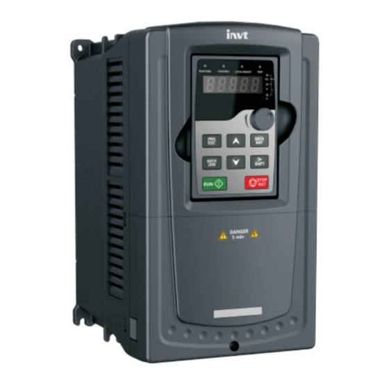
Goodrive300 Series VFD Product overview Rated output power Rated input current Rated output Model (kW) current (A) GD300-055G-6 GD300-075G-6 GD300-090G-6 GD300-110G-6 GD300-132G-6 GD300-160G-6 GD300-185G-6 GD300-200G-6 GD300-220G-6 GD300-250G-6 GD300-280G-6 GD300-315G-6 GD300-350G-6 GD300-400G-6 GD300-500G-6 GD300-560G-6 GD300-630G-6 Note: 1. The input current of VFDs 22–350kW is detected when the input voltage is 660V and there are no DC reactors and input/output reactors. - Page 20 Goodrive300 Series VFD Product overview Figure 3-8 Product structure Name Description Keypad port Connect the keypad. Upper cover Protect the internal parts and components. See Chapter 5 "Keypad operation procedure" for detailed Keypad information. See Chapter 9 "Maintenance and hardware fault Cooling fan diagnostics"...
-
Page 21: Chapter 4 Installation Guide
Goodrive300 Series VFD Installation guide Chapter 4 Installation guide 4.1 What this chapter contains The chapter describes the mechanical installation and electrical installation. • Only qualified electricians are allowed to carry out what described in this chapter. Please operate as the instructions in Chapter 1 "Safety precautions". - Page 22 The VFD should be installed upright to ensure the cooling effect. Note: Goodrive300 series VFDs should be installed in a clean and ventilated environment according to enclosure classification. Cooling air must be clean without corrosive gas or electrically conductive dust.
- Page 23 Goodrive300 Series VFD Installation guide 4.2.3 Installation mode The VFD can be installed in three different ways, depending on the frame size: a) Wall mounting, applicable for VFDs of 380V (≤315kW), 500V (≤75kW), and 660V (≤350kW) b) Flange mounting, applicable for VFDs of 380V (≤200kW), 500V (≤75kW), and 660V (≤200kW) c) Floor mounting, applicable for VFDs of 380V (220–500kW) and 660V (250–630kW)
- Page 24 Goodrive300 Series VFD Installation guide 4.2.4 Installation of one VFD Warm air Cool air Figure 4-3 Stand-alone installation Note: The minimum space of B and C is 100 mm. 4.2.5 Installation of multiple VFDs Warm air Cool air Figure 4-4 Parallel installation Note: ...
- Page 25 Goodrive300 Series VFD Installation guide 4.2.6 Vertical installation Wind board Wind board Figure 4-5 Vertical installation Note: Windscreen should be installed in vertical installation to prevent mutual impact and insufficient cooling.
- Page 26 Goodrive300 Series VFD Installation guide 4.2.7 Tilt installation Figure 4-6 Tilt installation Note: Ensure the separation of the wind input and output channels in tilt installation to prevent mutual impact.
-
Page 27: Standard Wiring
Goodrive300 Series VFD Installation guide 4.3 Standard wiring 4.3.1 Main circuit connection diagram 4.3.1.1 Main circuit connection diagram of VFDs of AC 3PH 380V (-15%)–440V (+10%) Brake resistor Single-phase 220V (optional) Output Input reactor reactor VFDs (≤30 kW) Output AC 3PH filter 380V (-15%)–440V (+10%) - Page 28 Goodrive300 Series VFD Installation guide 4.3.1.2 Main circuit connection diagram of VFDs of 3PH 380V (-10%)–550V (+10%) Brake resistor Single-phase 220V (optional) Output Input reactor VFDs (≤18.5 kW) reactor Output AC 3PH filter 380V (-10%)–550V (+10%) Input 50/60 Hz filter...
- Page 29 Goodrive300 Series VFD Installation guide output filter are optional parts. Please refer to Appendix D "Peripherial options and parts" for detailed information. A1 and A2 are standard parts. P1 and (+) are short circuited in factory, if it needs to connect with the DC rector, please remove the contact tag between P1 and (+).
- Page 30 Goodrive300 Series VFD Installation guide Figure 4-12 Main circuit terminals diagram of VFDs of 380V (7.5–11kW) and 500V (4–18.5kW) Figure 4-13 Main circuit terminals diagram of VFDs of 380V (15–18kW) Figure 4-14 Main circuit terminals diagram of VFDs of 380V (22–30kW)
- Page 31 Goodrive300 Series VFD Installation guide Figure 4-15 Main circuit terminals diagram of VFDs of 380V (37–55kW), 500V (22–55kW), and 660V (22–45kW) Figure 4-16 Main circuit terminals diagram of VFDs of 380V (75–110kW), 500V (75kW), and 660V (55–132kW) Figure 4-17 Main circuit terminals diagram of VFDs of 380V (132–200kW) and 660V (160–220kW)
- Page 32 Goodrive300 Series VFD Installation guide Figure 4-18 Main circuit terminals diagram of VFDs of 380V (220–315kW) and 660V (250–350kW) Figure 4-19 Main circuit terminals diagram of VFDs of 380V (350–500kW) and 660V (400–630kW) Terminal name 380V (≤30kW) 380V (≥37kW) Terminal Function description 500V (≤18.5kW)
- Page 33 Goodrive300 Series VFD Installation guide Terminal name 380V (≤30kW) 380V (≥37kW) Terminal Function description 500V (≤18.5kW) 500V (≥22kW) 660V DC reactor terminal P1 and (+) are connected with the terminals of the DC reactor terminal Braking resistor DC reactor. 2, braking unit...
- Page 34 Goodrive300 Series VFD Installation guide Fasten up all the cables on the outside of the VFD if allowed. The screw is The screw is not fastened. fastened. Figure 4-20 Correct installation of the screw 4.3.4 Control circuit wiring diagram Goodrive300 VFD...
- Page 35 Goodrive300 Series VFD Installation guide 4.3.5 Control circuit terminal diagram Figure 4-22 Control circuit terminals Terminal Description name +10V Local power supply +10 V 1. Input range: AI1/AI2 voltage and current can be chosen: 0–10 V/0–20mA; AI1 can be shifted by J3 while AI2 can be shifted by J4;...
- Page 36 Goodrive300 Series VFD Installation guide Terminal Description name 1. Switch capacity: 200mA/30V; 2. Range of output frequency: 0–50kHz Common port of +24V Common port of open collector output 1. Switch capacity: 200mA/30V; 2. Range of output frequency: 0–1kHz 485+ For 485 communication port, 485 differential signal port and standard 485 communication interfaces, use twisted pairs or shielded cables.
- Page 37 Goodrive300 Series VFD Installation guide Torque of Goodrive300 series VFDs: 3.5 lbf. in U-shaped short- U-shaped short- circuit connector circuit connector between +24V between COM and PW and CME Figure 4-23 U-shaped short-circuit positions If the signal is from NPN transistor, set the U-shaped short-circuit connector between +24V and PW as follows according to the used power supply.
-
Page 38: Layout Protection
Goodrive300 Series VFD Installation guide 4.4 Layout protection 4.4.1 Protecting the VFD and input power cable in short-circuit situations Protect the VFD and input power cable in short circuit situations and against thermal overload. Arrange the protection according to the following guidelines. -
Page 39: Chapter 5 Keypad Operation Procedure
5.2 Keypad The keypad is used to control Goodrive300 series VFDs, read the state data and adjust parameters. If you need to use the keypad in another place rather than on the VFD, use a network cable with a standard RJ45 crystal head as the extension cable. - Page 40 Goodrive300 Series VFD Keypad operation procedure Name Description LED for keypad operation, terminals operation and remote communication control LED off means that the VFD is in the LOCAL/REMOT keypad operation state; LED blinking means the VFD is in the terminals operation state;...
-
Page 41: Keypad Displaying
P07.02. 5.3 Keypad displaying The keypad displaying state of Goodrive300 series VFDs is divided into stopping state parameter, running state parameter, function code parameter editing state and fault alarm state and so on. 5.3.1 Displayed state of stopping parameter When the VFD is in the stopping state, the keypad will display stopping parameters which is shown in figure 5-2. - Page 42 Goodrive300 Series VFD Keypad operation procedure are: set frequency, bus voltage, input terminals state, output terminals state, PID given value, PID feedback value, torque set value, AI1, AI2, AI3, HDI, PLC and the current stage of multi-step speeds, pulse counting value, length value. P07.07 can select the parameter to be displayed or not by bit and 》/SHIFT can shift the parameters form left to right, QUICK/JOG (P07.02=2) can shift the...
-
Page 43: Keypad Operation
Figure 5-3 Sketch map of modifying parameters 5.4.2 How to set the password of the VFD Goodrive300 series VFDs provide password protection function to users. Set P7.00 to gain the password and the password protection becomes valid instantly after quitting from the function code editing state. - Page 44 Figure 5-4 Sketch map of password setting 5.4.3 How to watch the VFD state through function codes Goodrive300 series VFDs provide group P17 as the state inspection group. Users can enter into P17 directly to watch the state. All digits are blinking.
-
Page 45: Chapter 6 Function Parameters
This chapter lists and describes the function parameters. 6.2 Goodrive300 general series function parameters The function parameters of Goodrive300 series VFDs have been divided into 30 groups (P00–P29) according to the function, of which P18–P28 are reserved. Each function group contains certain function codes applying 3-level menus. - Page 46 Goodrive300 Series VFD Function parameters the password freely and the VFD will work as the last setting one. When P07.00 is set to 0, the password can be canceled. If P07.00 is not 0 during powering on, then the parameter is protected by the password.
- Page 47 Goodrive300 Series VFD Function parameters Function Default Name Detailed instruction of parameters Modify code value STOP/RST simultaneously in running state to make the VFD coast to stop. 1: Terminal ("LOCAL/REMOT" flickering) Carry out the running command control by the forward rotation, reverse rotation and forward...
- Page 48 1: AI1 2: AI2 3: AI3 Set the frequency by analog input terminals. Goodrive300 series VFDs provide 3 ways analog input terminals as the standard configuration, of which AI1/AI2 are the voltage/current option (0–10V/0–20mA) which can be shifted by jumpers; while AI3 is voltage input (-10V–+10V).
- Page 49 Goodrive300 Series VFD Function parameters Function Default Name Detailed instruction of parameters Modify code value 5: Simple PLC program setting The VFD runs at simple PLC program mode when P00.06=5 or P00.07=5. Set P10 (simple PLC and multi-step speed control) to select the...
- Page 50 DEC time means the time needed if the VFD model speeds down from the Max. Output frequency to 0Hz (P00.03). Goodrive300 series VFDs define four groups of ACC/DEC time which can be selected by P05. Depend The factory default ACC/DEC time of the VFD is P00.12...
- Page 51 Goodrive300 Series VFD Function parameters Function Default Name Detailed instruction of parameters Modify code value the reverse direction. FWD/REV indicator is on. Modify the function code to shift the rotation direction of the motor. This effect equals to the shifting the rotation direction by adjusting either two of the motor lines (U, V and W).
- Page 52 Goodrive300 Series VFD Function parameters Function Default Name Detailed instruction of parameters Modify code value Above 75kW 2kHz The advantage of high carrier frequency: ideal current waveform, little current harmonic wave and motor noise. The disadvantage of high carrier frequency:...
- Page 53 Goodrive300 Series VFD Function parameters Function Default Name Detailed instruction of parameters Modify code value VFD because of the bus voltage fluctuation. P00.17 Reserved Reserved ◎ 0: No operation 1: Restore the default value 2: Cancel the fault record Function Note: The function code will restore to 0 after P00.18...
- Page 54 Goodrive300 Series VFD Function parameters Function Default Name Detailed instruction of parameters Modify code value state. The starting frequency is not limited in the lower limit frequency. Output frequency fmax f1 set by P01.01 t1 set by P01.02 Setting range: 0.0–50.0s...
- Page 55 Goodrive300 Series VFD Function parameters Function Default Name Detailed instruction of parameters Modify code value 1: Coast to stop: after the stop command becomes valid, the VFD ceases the output immediately. And the load coasts to stop at the mechanical inertia.
- Page 56 Goodrive300 Series VFD Function parameters Function Default Name Detailed instruction of parameters Modify code value Output frequency f Forward Switch over after starting frequency Starting Switch over after frequency zero frequency Time t Deadzone Reverse time Setting range: 0.0–3600.0s Set the threshold point of the VFD:...
- Page 57 Goodrive300 Series VFD Function parameters Function Default Name Detailed instruction of parameters Modify code value won’t run and the system keeps in the protection state until the running command is canceled and enabled again. 1: The terminal running command is valid when powering on.
- Page 58 Goodrive300 Series VFD Function parameters Function Default Name Detailed instruction of parameters Modify code value power outage the power off and then power on. 0: Ddisable 1: Enable, if the starting need is met, the VFD will run automatically after waiting for the time defined by P01.22.
- Page 59 Goodrive300 Series VFD Function parameters Function Default Name Detailed instruction of parameters Modify code value Rated value frequency of 0.01Hz–P00.03 (Max. P02.01–P02.05 based 50.00 P02.02 ◎ asynchronous output frequency) nameplate motor 1 parameters. Goodrive35 series VFD Rated speed Depend provides parameter P02.03...
- Page 60 Goodrive300 Series VFD Function parameters Function Default Name Detailed instruction of parameters Modify code value Mutual change this group of Depend inductance of parameters at will. P02.09 0.1–6553.5 mH ○ asynchronous model motor 1 Non-load Depend current of P02.10 0.1–6553.5A ○...
- Page 61 Goodrive300 Series VFD Function parameters Function Default Name Detailed instruction of parameters Modify code value Number of Goodrive300 VFDs provide poles pairs for parameter autotuning P02.17 1–50 ◎ synchronous function. Correct parameter motor 1 autotuning depends on the correct setting of the name...
- Page 62 Goodrive300 Series VFD Function parameters Function Default Name Detailed instruction of parameters Modify code value according to the autotuning. this case, following calculate manually method. change the value of P02.23. counter-electrom otive force constant can be counted according to the...
- Page 63 Goodrive300 Series VFD Function parameters Function Default Name Detailed instruction of parameters Modify code value then: E=P/√3×I above formulas: n the rated rotation speed, P is the rated power and I rated current. Setting range: 0–10000 Initial pole position of P02.24...
- Page 64 Goodrive300 Series VFD Function parameters Function Default Name Detailed instruction of parameters Modify code value protection output current of the VFD and K is the motor coefficient protection coefficient. The smaller K is, the greater M is, and the more likely protection is implemented.
- Page 65 Goodrive300 Series VFD Function parameters Function Default Name Detailed instruction of parameters Modify code value Low switching parameters are: P03.03 P03.04. P03.02 5.00Hz ○ frequency parameters are gained according to the linear change of two groups of parameters. It is shown...
- Page 66 Goodrive300 Series VFD Function parameters Function Default Name Detailed instruction of parameters Modify code value coefficient of braking slip Current loop Note: P03.09 percentage 1 These two parameters adjust the PI adjustment 1000 ○ coefficient P parameter of the current loop which affects the dynamic response speed and control accuracy directly.
- Page 67 Goodrive300 Series VFD Function parameters Function Default Name Detailed instruction of parameters Modify code value vector control 2: AI2 3: AI3 4: Pulse frequency HDI setting upper-limit frequency 5: Multi-step setting upper-limit frequency 6: Modbus communication setting upper-limit Upper frequency frequency of P03.15...
- Page 68 Goodrive300 Series VFD Function parameters Function Default Name Detailed instruction of parameters Modify code value 4: HDI 5: Modbus communication 6: PROFIBUS\CANopen communication 7: Ethernet communication 8: Reserved Note: setting modes 1–9, 100% corresponds to three times of the motor current.
- Page 69 Goodrive300 Series VFD Function parameters Function Default Name Detailed instruction of parameters Modify code value time Build up a magnetic field inside the VFD to improve the torque performance during the starting process. The setting time: 0.000–10.000s Weak 0–8000 magnetic P03.26...
- Page 70 Goodrive300 Series VFD Function parameters Function Default Name Detailed instruction of parameters Modify code value the feature of the curve. Note: V in the below picture is the motor rated voltage and f is the motor rated frequency. Output voltage Torque-stepdown characteristics V/F curve (1.3 order)
- Page 71 Goodrive300 Series VFD Function parameters Function Default Name Detailed instruction of parameters Modify code value frequency 1 of through P04.03–P04.08. motor 1 V/F is generally set according to the load of the motor. Note:V1 < V2 < V3, f1 < f2 < f3. Too high low P04.04...
- Page 72 Goodrive300 Series VFD Function parameters Function Default Name Detailed instruction of parameters Modify code value Vibration control factor P04.10 at low ○ In SVPWM control mode, current fluctuation may frequency of occur to the motor at some frequency, especially motor 1 the motor with big power.
- Page 73 Goodrive300 Series VFD Function parameters Function Default Name Detailed instruction of parameters Modify code value voltage 3 of motor 2 V/F slip compensation P04.22 100.0% ○ gain of motor Vibration control factor P04.23 at low In SVPWM control mode, current fluctuation may ○...
- Page 74 Goodrive300 Series VFD Function parameters Function Default Name Detailed instruction of parameters Modify code value 10: Reserved Note: 100% corresponds to the rated voltage of the motor. The function code is the voltage displaying when Keypad P04.28 the voltage is set through keypad.
- Page 75 Goodrive300 Series VFD Function parameters Function Default Name Detailed instruction of parameters Modify code value S1 terminals 0: No function P05.01 function 1: Forward rotation operation ◎ selection 2: Reverse rotation operation 3: 3-wire control operation S2 terminals 4: Forward jogging P05.02...
- Page 76 Goodrive300 Series VFD Function parameters Function Default Name Detailed instruction of parameters Modify code value temporarily 34: DC brake 35: Shift the motor 1 into motor 2 36: Shift the command to the keypad 37: Shift the command to the terminals...
- Page 77 Goodrive300 Series VFD Function parameters Function Default Name Detailed instruction of parameters Modify code value communication, and the communication address is 0x200A. Set the control operation mode of the terminals. 0: 2-wire control 1; the enabling function and direction determination function are integrated.
- Page 78 Goodrive300 Series VFD Function parameters Function Default Name Detailed instruction of parameters Modify code value The direction control is as follows during operation: Previous Current direction direction Forward Reverse OFF→ON Reverse Forward Reverse Forward ON→OFF Forward Reverse ON→OFF Decelerate to stop SIn: 3-wire control;...
- Page 79 Goodrive300 Series VFD Function parameters Function Default Name Detailed instruction of parameters Modify code value Direction Forward OFF→ON Reverse Forward OFF→ON Reverse Decelerate ON→OFF to stop SIn: 3-wire operation control; FWD: Forward running; REV: Reverse running Note: For the 2-wire running mode, when the...
- Page 80 Goodrive300 Series VFD Function parameters Function Default Name Detailed instruction of parameters Modify code value Switch-off P05.19 delay of S3 0.000s ○ terminal Switch-on P05.20 delay of S4 0.000s ○ terminal Switch-off P05.21 delay of S4 0.000s ○ terminal Switch-on P05.22...
- Page 81 Goodrive300 Series VFD Function parameters Function Default Name Detailed instruction of parameters Modify code value delay of HDI terminal Lower limit of The function code defines the relationship P05.32 0.00V ○ between the analog input voltage and its Corresponding corresponding set value. If the analog input...
- Page 82 Goodrive300 Series VFD Function parameters Function Default Name Detailed instruction of parameters Modify code value of AI3 Setting range of P05.37: 0.00V–P05.39 Setting range of P05.38: -100.0%–100.0% Corresponding Setting range of P05.39: P05.37–10.00V P05.45 middle setting 0.0% ○ Setting range of P05.40: -100.0%–100.0% of AI3 Setting range of P05.41: 0.000s–10.000s...
- Page 83 Goodrive300 Series VFD Function parameters Function Default Name Detailed instruction of parameters Modify code value P06 Group Output terminals The function selection of the high-speed pulse output terminals. 0: Open collector high speed pulse output: The Max.pulse frequency 50.0kHz. P06.00 HDO output ◎...
- Page 84 Goodrive300 Series VFD Function parameters Function Default Name Detailed instruction of parameters Modify code value output 26: Voltage establishment finished 27–30: Reserved The function code is used to set the pole of the output terminal. When the current bit is set to 0, the input terminal is anode.
- Page 85 Goodrive300 Series VFD Function parameters Function Default Name Detailed instruction of parameters Modify code value 5: Output current (relative to 2 times the rated current of the motor) 6: Output voltage (relative to 1.5 times the rated voltage of the VFD)
- Page 86 Goodrive300 Series VFD Function parameters Function Default Name Detailed instruction of parameters Modify code value AO1 output P06.21 10V (20mA) 0.000s ○ filter time Lower output P06.22 0.0% ○ limit of AO2 Corresponding P06.23 AO2 output of 0.00V ○ lower limit 0.0%...
- Page 87 Goodrive300 Series VFD Function parameters Function Default Name Detailed instruction of parameters Modify code value Please remember all users’ passwords. Retreat editing state of the function codes and the password protection will become valid in minute. If the valid password is available, press PRG/ESC to enter into the editing state of the function codes, and then "0.0.0.0.0"...
- Page 88 Goodrive300 Series VFD Function parameters Function Default Name Detailed instruction of parameters Modify code value to clear the set value of UP/DOWN. 5: Coast to stop. Press QUICK/JOG to coast to stop. 6: Shift the given manner of running commands.
- Page 89 Goodrive300 Series VFD Function parameters Function Default Name Detailed instruction of parameters Modify code value BIT9: PID feedback value (% on) BIT10: input terminals state BIT11: output terminals state BIT12: torque set value (% on) BIT13: pulse counter value BIT14: length value...
- Page 90 Goodrive300 Series VFD Function parameters Function Default Name Detailed instruction of parameters Modify code value BIT15: reserved Frequency 0.01–10.00 P07.08 1.00 ○ coefficient Displayed frequency=running frequency × P07.08 Rotation 0.1–999.9% P07.09 speed Mechanical rotation speed =120 × displayed 100.0% ○...
- Page 91 Goodrive300 Series VFD Function parameters Function Default Name Detailed instruction of parameters Modify code value Factory bar P07.22 0x0000–0xFFFF ● code 2 Factory bar P07.23 0x0000–0xFFFF ● code 3 Factory bar P07.24 0x0000–0xFFFF ● code 4 Factory bar P07.25 0x0000–0xFFFF ●...
- Page 92 Goodrive300 Series VFD Function parameters Function Default Name Detailed instruction of parameters Modify code value Previous 3 27: Parameter uploading fault (UPE) P07.30 ● fault type 28: Parameter downloading fault (DNE) 29: PROFIBUS communication fault (E-DP) Previous 4 P07.31 ●...
- Page 93 Goodrive300 Series VFD Function parameters Function Default Name Detailed instruction of parameters Modify code value frequency at last fault Output voltage P07.43 ● at last fault The output P07.44 current at last 0.0A ● fault Bus voltage at P07.45 0.0V ●...
- Page 94 ○ model Depend See P00.11 and P00.12 for detailed definition. P08.02 ACC time 3 Goodrive300 series define four groups of ○ ACC/DEC time which can be selected by P5 model group. The first group of ACC/DEC time is the Depend factory default one.
- Page 95 Goodrive300 Series VFD Function parameters Function Default Name Detailed instruction of parameters Modify code value frequency 1 frequency, the VFD will run at the edge of the jumping frequency. Jump The VFD can avoid the mechanical resonance P08.10 frequency 0.00Hz ○...
- Page 96 Goodrive300 Series VFD Function parameters Function Default Name Detailed instruction of parameters Modify code value corresponds to the sudden jumping frequency. The raising time of the traverse frequency: The time from the lowest point to the highest one. The declining time of the traverse frequency: The time from the highest point to the lowest one.
- Page 97 Goodrive300 Series VFD Function parameters Function Default Name Detailed instruction of parameters Modify code value pulse occurs. The value of P08.26 cannot be greater than that of P08.25. The function is illustrated as below: The set count value Y, HDO, is reached.
- Page 98 Goodrive300 Series VFD Function parameters Function Default Name Detailed instruction of parameters Modify code value 0: Disabled 1: Enabled 0x00–0x14 FDT1 When output frequency exceeds electrical level corresponding frequency of FDT electrical level, 50.00 P08.32 ○ detection the multi-function digital output terminals will value output the signal of "frequency level detect FDT"...
- Page 99 Goodrive300 Series VFD Function parameters Function Default Name Detailed instruction of parameters Modify code value Output frequency Detectionn range Set frequency Time RO1, RO2 Time Setting range: 0.00Hz–P00.03 (Max. frequency) This parameter is used to control the enabling of the internal braking pipe inside the VFD.
- Page 100 Goodrive300 Series VFD Function parameters Function Default Name Detailed instruction of parameters Modify code value carrier frequency will limit to 4k if it exceeds 4k at low speed 2: No limit LED ones 0: Invalid Overmodulatio 1: Valid P08.41 ◎...
- Page 101 Goodrive300 Series VFD Function parameters Function Default Name Detailed instruction of parameters Modify code value LED tens: frequency control selection 0: Only valid when P00.06=0 or P00.07=0 1: All frequency means are valid 2: When the multi-step are priority, it is invalid to...
- Page 102 Goodrive300 Series VFD Function parameters Function Default Name Detailed instruction of parameters Modify code value 0: Invalid. 100–150: The bigger the coefficient, the stronger the braking is. This VFD is used to increase the magnetic flux to decelerate the motor. The energy generated by the motor during braking can be converter into heat energy by increasing the magnetic flux.
- Page 103 Goodrive300 Series VFD Function parameters Function Default Name Detailed instruction of parameters Modify code value 8: Ethernet communication set 9: Reserved The setting target of procedure PID is a relative one, 100% of the setting equals to 100% of the response of the controlled system.
- Page 104 Goodrive300 Series VFD Function parameters Function Default Name Detailed instruction of parameters Modify code value control during wrapdown. The function is applied to the proportional gain P of PID input. P determines the strength of the whole PID adjuster. The parameter of 100 means that when Proportional P09.04...
- Page 105 Goodrive300 Series VFD Function parameters Function Default Name Detailed instruction of parameters Modify code value Setting range: 0.000–10.000s The output of PID system is the maximum deviation corresponding to close loop reference. As shown in the diagram below, PID adjustor stops to work during the deviation limit.
- Page 106 Goodrive300 Series VFD Function parameters Function Default Name Detailed instruction of parameters Modify code value Setting range of P09.11: 0.0–100.0% Setting range of P09.12: 0.0–3600.0s 0x0000–0x1111 LED ones: 0: Keep on integral adjustment when the frequency achieves the upper and low limit; the...
- Page 107 --f –f Running time and it can be set continuously. P10.11 0.0s ○ of step 4 Goodrive300 series VFDs can set 16 stages P10.12 Multi-step 0.0% speed, selected by the combination of multi-step ○...
- Page 108 Goodrive300 Series VFD Function parameters Function Default Name Detailed instruction of parameters Modify code value speed 5 terminals 1–4 (select the setting by S terminals, corresponding function codes Running time P10.13 0.0s ○ P05.01–P05.09), corresponding to the speed 1 to of step 5 speed 15.
- Page 109 Goodrive300 Series VFD Function parameters Function Default Name Detailed instruction of parameters Modify code value Running time P10.31 0.0s ○ of step 14 Multi-step P10.32 0.0% ○ speed 15 Running time P10.33 0.0s ○ of step 15 Simple PLC Below is the detailed instruction: 0–7 step...
- Page 110 Goodrive300 Series VFD Function parameters Function Default Name Detailed instruction of parameters Modify code value Setting range: -0x0000–0xFFFF 0: Restart from the first step; stop during running (cause by the stop command, fault or power loss), run from the first stage after restart.
- Page 111 Goodrive300 Series VFD Function parameters Function Default Name Detailed instruction of parameters Modify code value sudden power loss Note: 1. Adjust the parameter properly to avoid the stopping caused by VFD protection during the switching of the grid. 2. Disable input phase loss protection to enable this function.
- Page 112 Goodrive300 Series VFD Function parameters Function Default Name Detailed instruction of parameters Modify code value During the running of the VFD, it will detect the output current and compare it with the limit level Automatic P11.06 160.0% ◎ defined in P11.06. If it exceeds the level, the VFD...
- Page 113 Goodrive300 Series VFD Function parameters Function Default Name Detailed instruction of parameters Modify code value LED tens: 0: The VFD continues to work after underload pre-alarm 1: The VFD continues to work after underload pre-alarm and the VFD stops to run after overload...
- Page 114 Goodrive300 Series VFD Function parameters Function Default Name Detailed instruction of parameters Modify code value Speed Actual detection value Set detection value Time In running Fault output t1<t2, so the VFD continues to work t2=P11.15 Setting range of P11.15: 0.0–10.0s...
- Page 115 Goodrive300 Series VFD Function parameters Function Default Name Detailed instruction of parameters Modify code value motor 2 the motor and the standard one is huge, the features of the VFD will decrease. Note: Reset the rated power motor (P12.01), initialize the motor parameter of P12.02–P12.05.
- Page 116 Goodrive300 Series VFD Function parameters Function Default Name Detailed instruction of parameters Modify code value Magnetic saturation P12.13 coefficient 3 0.0–100.0% 57.0% ◎ for the iron core of AM2 Magnetic saturation P12.14 coefficient 4 0.0–100.0% 40.0% ◎ for the iron...
- Page 117 Goodrive300 Series VFD Function parameters Function Default Name Detailed instruction of parameters Modify code value synchronous value of P12.20–P12.22 will model motor 2 renew automatically. These parameters basic Quadrature parameters controlled axis Depend vectors which directly impact P12.22 inductance of 0.01–655.35mH...
- Page 118 Goodrive300 Series VFD Function parameters Function Default Name Detailed instruction of parameters Modify code value counter-electrom otive force constant E’(V/1000r/min), then: E=E’×n /100 3. Iif the name plate does not designate the above parameters, then: E=P/√3×I In the above formulas: n...
- Page 119 Goodrive300 Series VFD Function parameters Function Default Name Detailed instruction of parameters Modify code value Times of motor overload M = Iout/(In×K) In is the rated current of the motor, Iout is the output current of the VFD and K is the motor protection coefficient.
- Page 120 Goodrive300 Series VFD Function parameters Function Default Name Detailed instruction of parameters Modify code value source current 0: No test Original pole P13.01 1: High-frequency superposition (reserved) ◎ test mode 2: Pulse superposition Source current is the positioning current of the magnetic pole position.
- Page 121 Goodrive300 Series VFD Function parameters Function Default Name Detailed instruction of parameters Modify code value compensation to the motor, please adjust the parameter. coefficient Setting range: 0–100.0% Braking When P01.00=0 during the starting of the VFD, P13.13 current of set P13.14 to a non-zero value to enter the short 0.0%...
- Page 122 Goodrive300 Series VFD Function parameters Function Default Name Detailed instruction of parameters Modify code value the VFD must be the same. Otherwise, the communication is not applied. The bigger the baud rate, the quicker the communication speed. The data format between the upper monitor and the VFD must be the same.
- Page 123 Goodrive300 Series VFD Function parameters Function Default Name Detailed instruction of parameters Modify code value 0x00–0x11 LED ones: 0: Write with response: the VFD will respond to all reading and writing commands of the upper monitor. Communicatio 1: Write without response: the VFD only responds P14.06...
- Page 124 Goodrive300 Series VFD Function parameters Function Default Name Detailed instruction of parameters Modify code value PZD9 motor) P15.09 ○ receiving 8: Braking torque upper limit (0–2000,1000 corresponds to 100.0% of the rated current of the PZD10 P15.10 ○ motor) receiving...
- Page 125 Goodrive300 Series VFD Function parameters Function Default Name Detailed instruction of parameters Modify code value Temporarily P15.24 variable 1 for 0–65535 ○ PZD sending 0.0 (invalid),0.1–60.0s When this function code is set as 0.0, this Fault tiem of function is invalid.
- Page 126 Goodrive300 Series VFD Function parameters Function Default Name Detailed instruction of parameters Modify code value format address: P16.03 IP address 3 ◎ P16.09.P16.10.P16.11.P16.12. P16.04 IP address 4 ◎ For example: IP address is 192.168.0.1. Subnet mask P16.05 ◎ 0–255 Subnet mask P16.06...
- Page 127 Goodrive300 Series VFD Function parameters Function Default Name Detailed instruction of parameters Modify code value Display the current output torque of the VFD. P17.09 Output torque 0.0% ● Range: -250.0–250.0% Evaluated Evaluate the motor rotor frequency on close loop P17.10 motor vector.
- Page 128 Goodrive300 Series VFD Function parameters Function Default Name Detailed instruction of parameters Modify code value AI3 input Display analog AI2 input signal. P17.21 0.00V ● voltage Range: -10.00–10.00V HDI input Display HDI input frequency. 0.000 P17.22 ● frequency Range: 0.000–50.000kHz Display PID given value.
- Page 129 Goodrive300 Series VFD Function parameters Function Default Name Detailed instruction of parameters Modify code value reference control mode. Range: -3000.0–3000.0A Display the value of inlet current in AC side. P17.35 AC current 0.0A ● Range: 0.0–5000.0A Display the output torque. Positive value is in the electromotion state, and negative is in the power P17.36...
-
Page 130: Chapter 7 Basic Operation Instruction
Goodrive300 Series VFD Basic operation instruction Chapter 7 Basic operation instruction 7.1 What this chapter contains This chapter describes the internal function modules of the VFD in details. • Ensure that all terminals are connected properly and tightly. • Ensure that the power of the motor corresponds to that of the VFD. - Page 131 Goodrive300 Series VFD Basic operation instruction Start Power on after right wiring Restore to the factory parameters(P00.18=1) Motor type selection (P02.00) Set P02.01~P02.05 Set P02.15~P02.19 Press QUICK/JOG to jog If the rotation direction is wrong, power off to change the wires and repower on Set autotuning Set P00.15=2 to achieve...
- Page 132 Goodrive300 Series VFD Basic operation instruction Besides P00.01 and P00.02, terminal command setting can also used to set the running command channel. Current running Multi-function Multi-function Multi-function command terminal 38 terminal 36 terminal 37 channel Switch to Switch to keypad Switch to terminal P00.01...
- Page 133 Goodrive300 Series VFD Basic operation instruction Function Default Name Detailed instruction of parameters code value Rated frequency of P02.02 0.01Hz–P00.03 (Max. output frequency) 50.00Hz asynchronous motor 1 Rated speed of Depend P02.03 1–36000rpm asynchronous motor 1 on model Rated voltage of Depend P02.04...
-
Page 134: Vector Control
Goodrive300 series VFDs are embedded speedless sensor vector control calculation for driving both asynchronous motors and synchronous motors. Because the core calculation of vector control is based on exact motor parameter models, the accuracy of motor parameter will impact on the performance of vector control. - Page 135 Goodrive300 Series VFD Basic operation instruction R S T Rectifying bridge φ Calculate excitation Park Inverter current Transformation pulse bridge Calculate torque current φ Position Voltage observation detection Speed identification Flux linkage detection Park Clark Current Transformation transformation detection Motor...
- Page 136 Goodrive300 Series VFD Basic operation instruction Function Default Name Detailed instruction of parameters code value Compensation coefficient P03.07 of electromotion slip in 50%–200% 100% vector control Compensation coefficient P03.08 of braking slip in vector 50%–200% 100% control Current loop proportional P03.09...
- Page 137 Goodrive300 Series VFD Basic operation instruction Function Default Name Detailed instruction of parameters code value 4: Pulse frequency HDI 5: Multi-step 6: Modbus communication 7: PROFIBUS/CANopen communication 8: Ethernet communication 9: Reserved Note: For setting modes of 1–9, 100% corresponds to the maximum frequency.
-
Page 138: Svpwm Control
0.0–200.0% 7.4 SVPWM control Goodrive300 series VFDs provide internal SVPWM control which can be used in the cases where it does not need high control accuracy. It is also recommended to use SVPWM control when one VFD drives multiple motors. - Page 139 Motor vibration occurs frequently when applying SVPWM control mode in the cases where high power is needed. In order to settle this problem, Goodrive300 series VFDs add two function codes which are set to control the vibration factors. The user can set the corresponding function code...
- Page 140 Goodrive300 Series VFD Basic operation instruction Note: Bigger the set value, more effective the control. If the set value is too big, overcurrent may occur to the motor. 5. User-defined V/F curve (V/F seperation) function...
- Page 141 Goodrive300 Series VFD Basic operation instruction When the user selects the user-defined V/F curve function in Goodrive300 series VFDs, they can set the given channel of voltage and frequency and the corresponding ACC/DEC time, or the two can combinate to form a real-time curve.
- Page 142 Goodrive300 Series VFD Basic operation instruction Function Default Name Description code value frequency 1 of motor 1 P04.04 0.0%–110.0% 0.0% voltage 1 of motor 1 P04.05 P04.03– P04.07 00.00Hz frequency 2 of motor 1 P04.06 0.0%–110.0% 0.0% voltage 2 of motor 1 P04.07...
-
Page 143: Torque Control
0.0% 7.5 Torque control Goodrive300 series VFDs support two kinds of control mode: torque control and rotation speed control. The core of rotation speed is that the whole control focuses on the stable speed and ensures the setting speed is the same as the actual running speed. The Max. Load sould be in the range of... - Page 144 Goodrive300 Series VFD Basic operation instruction the torque limit. The core of torque control is that the whole control focues on the stable torque and ensures the setting torque is the same as the actual output torque. At the same time, the output...
- Page 145 Goodrive300 Series VFD Basic operation instruction Function Default Name Detailed instruction of parameters code value 0: Sensorless vector control mode 0 (applicable to AM and SM) Speed control 1: Sensorless vector control mode 1 (applicable P00.00 mode to AM) 2: SVPWM control mode (applicable to AM and 0: Torque control is invalid 1: Keypad setting torque (P03.12)
-
Page 146: Parmeters Of The Motor
Goodrive300 Series VFD Basic operation instruction Function Default Name Detailed instruction of parameters code value 9: Reserved Keypad setting for upper frequency of P03.16 0.00Hz–P00.03 (Max. frequency) 50.00 Hz forward rotation in torque control Keypad setting for upper frequency of P03.17... - Page 147 It is proper to de-couple the motor from the load during autotune when necessary. Goodrive300 series VFDs can drive both asynchronous motors and synchronous motors. And at the same time, they can support two sets of motor parameters which can shift between two motors through multi-function digital input terminal or communication.
- Page 148 Goodrive300 Series VFD Basic operation instruction Ready P00.01=0 P02.00 P02.00=1 P02.00=0 P02.19) P02.05) (P02.12 – (P02.01 – P00.15 P00.15=1 P00.15=2 P00.15=3 Press "RUN" to begin autotuning Autotuning Display -END- " " Autotuning end Note: 1. Set the motor parameters according to the name plate of the motor.
- Page 149 Goodrive300 Series VFD Basic operation instruction make the motor is in a static and empty state, otherwise the result of autotune is incorrect. The asynchronous motors can autotune the parameters of P02.06–P02.10, while the synchronous motors can autotune the parameters of P02.20–P02.23.
- Page 150 Goodrive300 Series VFD Basic operation instruction Function Default Name Detailed instruction of parameters code value Leakage inductance of Depend P02.08 0.1–6553.5mH asynchronous motor 1 on model Mutual inductance of Depend P02.09 0.1–6553.5mH asynchronous motor 1 on model Non-load current of Depend P02.10...
- Page 151 Goodrive300 Series VFD Basic operation instruction Function Default Name Detailed instruction of parameters code value 0: Disabled 1: Enabled 0x00–0x14 0: Asynchronous motor P12.00 Motor type 2 1: Synchronous motor Rated power of Depend P12.01 0.1–3000.0kW asynchronous motor 2 on model Rated frequency of P12.02...
-
Page 152: Start-Up And Stop Control
Goodrive300 Series VFD Basic operation instruction Function Default Name Detailed instruction of parameters code value Direct axis inductance of Depend P12.21 0.01–655.35mH synchronous motor 2 on model Quadrature axis Depend P12.22 inductance of 0.01–655.35mH on model synchronous motor 2 Back EMF constant of P12.23... - Page 153 Goodrive300 Series VFD Basic operation instruction...
- Page 154 Goodrive300 Series VFD Basic operation instruction 2. The starting logic figure of starting after the restarting function becomes valid during the normal powering on. Standby Keypad Stop Operation status Stop before power outage Restart after Communication power outage Waiting time of restart...
- Page 155 Goodrive300 Series VFD Basic operation instruction Function Default Name Detailed instruction of parameters code value P00.12 Depend DEC time 1 0.0–3600.0s on model 0: Start-up directly P01.00 Start mode 1: Start-up after DC braking 2: Start-up after rotation speed tracking 1 Starting frequency of P01.01...
- Page 156 Goodrive300 Series VFD Basic operation instruction Function Default Name Detailed instruction of parameters code value valid when powering on Action if running 0: Run at the lower-limit frequency frequency<lower limit P01.19 1: Stop frequency 2: Hibernation (valid when lower limit>0) Hibernation restore delay P01.20...
-
Page 157: Frequency Setting
7.8 Frequency setting Goodrive300 series VFDs can set the frequency by various means. The given channel can be divided into main given channel and assistant given channel. There are two mian given channels: A frequency given channel and B frequency given channel. - Page 158 P08.42 tens setting Digital enabling (frequency control potentiometer selection) Goodrive300 series VFDs support the shifting between different given channels, and the detailed shifting rules are as below: Multi-function Multi-function Multi-function terminal Current given terminal function 14 terminal function 15...
- Page 159 Goodrive300 Series VFD Basic operation instruction When select multi-function terminal UP (10) and DOWN (11) to set the internal assistant frequency, P08.44 and P08.45 can be set to increase or decrease the set frequency quickly. UP terminal frequency increasing integral rate P08.45 DOWN terminal frequency increasing integral rate P08.46...
- Page 160 Goodrive300 Series VFD Basic operation instruction Function Default Name Detailed instruction of parameters code value 5.09 terminals Decreasing frequency setting (S1–S8, HDI) function (DOWN) selection 12: Cancel the frequency change setting 13: Shift between A setting and B setting 14: Shift between combination setting...
-
Page 161: Analog Input
Range: 0.00Hz–P00.03 7.9 Analog input Goodrive300 series VFDs have three analog input terminals and 1 high-speed pulse input terminals (of which, AI1 and AI2 are 0–10V/0–20mA and Al can select voltage input or current input by J3, AI2 can select voltage input or current input by J4 and AI3 is for -10–10V) as the standard configuration. - Page 162 Goodrive300 Series VFD Basic operation instruction AI1 input voltage Analog input curve setting Analog input filter P17.19 P05.32 P05.33 P05.36 P05.34 AI2 input voltage P05.35 P17.20 P05.37 P05.38 P05.41 P05.39 AI3 input voltage P05.40 P17.21 P05.42 P05.43 P05.48 P05.44 P05.45 P05.46...
-
Page 163: Analog Output
7.10 Analog output Goodrive300 series VFDs have 2 analog output terminals (0–10V or 0–20mA) and 1 high speed pulse output terminal. Analog output signal can be filtered and the maximum and minimum values can be adjusted. The analog output signals can be proportional to motor speed, output frequency, output... - Page 164 Goodrive300 Series VFD Basic operation instruction Analog output curve setting Analog output selection Analog output filter setting P06.17 P06.18 P06.14 P06.21 P06.19 P06.20 (default value is 0) P06.22 P06.23 P06.15 P06.26 P06.24 P06.25 (default value is 0) P06.00 (HDO output type selection) P06.27...
- Page 165 Goodrive300 Series VFD Basic operation instruction Set value Function Instructions communication Set value 2 of Modbus -1000–1000,1000 corresponds to 100.0% communication Setting value 1 of PROFIBUS/CANOPEN -1000–1000,1000 corresponds to 100.0% communication Setting value 2 of PROFIBUS/CANOPEN -1000–1000,100 corresponds to 100.0%...
- Page 166 Goodrive300 Series VFD Basic operation instruction Function Detailed instruction of parameters Default Name code value 7: Output power (relative to 2 times the rated power of the motor) 8: Set torque value (relative to 2 times the rated torque of the motor)
-
Page 167: Digital Input
0.000s 7.11 Digital input Goodrive300 series VFDs have 8 programmable digital input terminals and 1 open circuit electrode output terminal in the standard configuration. All functions of the digital input terminals are programmable by the function codes. Open collector input can be selected into high speed pulse input terminal or common switch input terminal by function code. - Page 168 Goodrive300 Series VFD Basic operation instruction This parameter is used to set the function corresponds to the digital multi-function terminals. Note: two different multi-function terminals cannot be set as one function. Function Instructions value The VFD does not work even there is input signal. It is...
- Page 169 Goodrive300 Series VFD Basic operation instruction Function Instructions value Frequency increasing/decreasing setting clear terminal can cancel the assistant channel frequency set by the internal UP/DOWN of the VFD to make the given frequency restore to the frequency given by the main given frequency channel.
- Page 170 Goodrive300 Series VFD Basic operation instruction Function Instructions value PLC continues to run. Temporal PID invalid and the VFD will output at the PID control pause current frequency. The VFD will stop at the current output and after Traverse pause (stop at the...
- Page 171 Goodrive300 Series VFD Basic operation instruction Function Instructions value communication command channel will be shifted into communication running command channel and the running command channel will come back to the original state if the function terminal is invalid. Perform pre-exciting if the terminal is valid until the Pre-excitation commands terminal is invalid.
- Page 172 Goodrive300 Series VFD Basic operation instruction Function Default Name Detailed instruction of parameters code value and B setting 16: Multi-step speed terminal 1 17: Multi-step speed terminal 2 18: Multi-step speed terminal 3 19: Multi- step speed terminal 4 20: Multi- step speed pause...
- Page 173 Goodrive300 Series VFD Basic operation instruction Function Default Name Detailed instruction of parameters code value BIT0: S1 virtual terminal BIT1: S2 virtual terminal BIT2: S3 virtual terminal BIT3: S4 virtual terminal BIT4: S5 virtual terminal BIT5: S6 virtual terminal BIT6: S7 virtual terminal...
-
Page 174: Digital Output
7.12 Digital output Goodrive300 series VFDs have 2 relay output terminals, 1 open collector output terminal Y, and 1 high-speed pulse output terminal (HDO) in the standard configuration. All functions of the digital output terminals are programmable by using function codes, where the HDO can be set to high-speed... - Page 175 Goodrive300 Series VFD Basic operation instruction Digital switch-off delay time P06.05 Output polarity Digital output Digital switch-on delay time P17.12 P06.06 P06.07 T delay P06.01 T delay Fault? (Default value is 0) Faul P07.38 P06.08 P06.09 T delay P06.02 T delay (Default value is 0) P06.00...
- Page 176 Goodrive300 Series VFD Basic operation instruction Set value Function Instructions VFD is the upper limit frequency. Output ON signal when the running frequency of the Lower-limit frequency arrival VFD is the lower limit frequency. When the main circuit and the control circuit is...
- Page 177 Goodrive300 Series VFD Basic operation instruction Set value Function Instructions value is 1 and output the signal of OFF if the set value is 0. DC bus voltage The output is vlaid when the bus voltage reaches the establishment finished undervoltage point of the inverter.
-
Page 178: Simple Plc
Goodrive300 Series VFD Basic operation instruction Function Default Name Detailed instruction of parameters code value Ethernet communication virtual terminals output 26: Voltage establishment finished 27–30: Reserved Polarity of output P06.05 0x00–0x0F 0x00 terminals P06.06 Y switch-on delay time 0.000–50.000s 0.000s P06.07... - Page 179 Goodrive300 Series VFD Basic operation instruction Digital output 16 Simple PLC stage completion 200ms Digital output 17 Simple PLC cycle completion 200ms Related parameters Function Default Name Detailed instruction of parameters code value 0: Stop after running once 1: Run at the final value after running P10.00...
-
Page 180: Multi-Step Speed Running
7.14 Multi-step speed running Set the parameters when the VFD carries out multi-step speed running. Goodrive300 series VFDs can set 16 stage speed which can be selected by the combination code of multi-step speed terminals 1–4. They correspond to multi-step speed 0 to 15. - Page 181 Goodrive300 Series VFD Basic operation instruction P10.02 multi-stage speed 0 BIT0 P10.34 P10.03 the running time of stage 0 BIT1 Terminal function 16 Multi-stage speed The ACC/DEC time selection terminal 1 of Stage 0~7 of PLC Terminal function 17 P10.04 multi-stage speed 1...
-
Page 182: Pid Control
Goodrive300 Series VFD Basic operation instruction Function Default Name Detailed instruction of parameters code value P10.15 Running time of step 6 0.0–6553.5s (min) 0.0s P10.16 Multi-step speed 7 -100.0–100.0% 0.0% P10.17 Running time of step 7 0.0–6553.5s (min) 0.0s P10.18 Multi-step speed 8 -100.0–100.0%... - Page 183 Goodrive300 Series VFD Basic operation instruction Keypad setting PID given P09.00 PID stop P09.01 Keypad (PID given source selection) adjustment PID given value P09.09 Set frequency Terminal function 25 (the upper limit of PID PID control pause P17.23 output )...
- Page 184 Goodrive300 Series VFD Basic operation instruction PID parameter setting for detailed information) to make proportional adjustment is the only method to PID. Set the input as 60%–70% of the permitted Max. Value and increase gain P from 0 until the system vibration occurs, vice versa, and record the PID value and set it to 60%–70% of the current...
- Page 185 Goodrive300 Series VFD Basic operation instruction integral time (Ti) to control the vibration for the strong integration. Before adjustment Response After adjustment Time Control short vibration Short vibration period and the same set value with the derivative time (Td) mean that the derivative time is strong.
- Page 186 Goodrive300 Series VFD Basic operation instruction Function Default Name Detailed instruction of parameters code value 2: AI3 3: HDI 4: Modbus communication feedback 5: PROFIBUS/CANopen communication feedback 6: Ethernet communication feedback 7: Reserve 0: PID output is positive P09.03 PID output feature 1: PID output is negative P09.04...
-
Page 187: Traverse Running
Goodrive300 Series VFD Basic operation instruction Function Default Name Detailed instruction of parameters code value the trend between the reference and the feedback changes, the integration will change with the trend quickly. LED tens: P00.08 is 0 0: The same with the setting direction; if... -
Page 188: Pulse Counter
7.17 Pulse counter Goodrive300 series VFDs support pulse counter which can input counting pulse through HDI terminal. When the actual length is longer than or equal to the set length, the digital output terminal can output length arrival pulse signal and the corresponding length will clear automatically. -
Page 189: Fixed-Length Control
Specified count value 0–P08.25 P17.18 Count value 0–65535 7.18 Fixed-length control Goodrive300 series VFDs support fixed-length control function which can input length counting pulse through HDI, and then count the actual length according to the internal counting formula. If the actual... -
Page 190: Fault Procedure
Length ratio 0.001–10.000 1.000 Length correcting P08.24 0.001–1.000 1.000 coefficient P17.17 Length 0–65535 Display HDI input frequency P17.22 HDI input frequency 0.00kHz Range: 0.00–50.00kHz 7.19 Fault procedure Goodrive300 series VFDs provide sufficient fault procedure information for the convenience of user’s application. - Page 191 Goodrive300 Series VFD Basic operation instruction In running Fault occurs and the keypad displays the fault code Look up the fault reason according to the fault code According to P07.33~P07.40 to estimate the best reason Rectify the fault Consult INVT...
- Page 192 Goodrive300 Series VFD Basic operation instruction Function Default Name Detailed instruction of parameters code value 13: Input side phase loss (SPI) 14: Output side phase loss (SPO) 15: Overheat of the rectifier module (OH1) 16: Overheat fault of the inverter module...
- Page 193 Goodrive300 Series VFD Basic operation instruction Function Default Name Detailed instruction of parameters code value fault The Max. temperature at P07.38 0.0° C current fault Input terminals state at P07.39 current fault Output terminals state at P07.40 current fault Running frequency at last P07.41...
-
Page 194: Chapter 8 Fault Tracking
8.5 Fault instruction and solution Do as the following after the VFD fault: 1. Check to ensure there is nothing wrong with the kepad. If not, please contact with the local INVT office. 2. If there is nothing wrong, please check P07 and ensure the corresponding recorded fault parameters to confirm the real state when the current fault occurs by all parameters. - Page 195 Goodrive300 Series VFD Fault tracking Code Fault Cause Solution Inverter unit W wires is not good OUt3 phase Short-to-ground occurs. protection Accelerating Check the input power overvoltage Check if the DEC time of the load is too short or the VFD starts Decelerating The input voltage is abnormal...
- Page 196 Goodrive300 Series VFD Fault tracking Code Fault Cause Solution Reset the rotating motor Avoid the restarting after stopping. The voltage of the grid is too Check the power of the grid low. Select a VFD with bigger power. The load is too heavy.
- Page 197 Goodrive300 Series VFD Fault tracking Code Fault Cause Solution parameters from autotune and Check the motor connection and the standard parameter is huge set the parameter. Autotune overtime Check if the upper limit frequency is above 2/3 of the rated frequency.
- Page 198 Goodrive300 Series VFD Fault tracking Code Fault Cause Solution fault The keypad wire is too long Change the hardware and ask for affected strong service. interference. Repack-up the data in the keypad. There is mistake on the data storage of the keypad.
- Page 199 Goodrive300 Series VFD Fault tracking Code Fault Cause Solution power. Check the load and ensure it is normal. Speed The load is too heavy or Increase the detection time. deviation fault stalled. Check whether control parameters are normal. The control parameters of the Check the load and ensure it is...
-
Page 200: Common Fault Analysis
Goodrive300 Series VFD Fault tracking 8.6 Common fault analysis 8.6.1 The motor does not work The motor does not rotate If the POWER is on or not? If the contactor closes on Switch on the air If there is displaying on... - Page 201 Goodrive300 Series VFD Fault tracking 8.6.2 Motor vibration Motor vibration or abnormal noise Please set right Check the motor parameter motor type and or motor type is right or not parameters Perform parameter Perform right autotune or not parameter autotune...
- Page 202 Goodrive300 Series VFD Fault tracking 8.6.3 Overvoltage OV fault Check if the voltage range is Ensure the power supply in the standard one or not ? meets the need Check If UVW is short Settle the short circuit and Circuited to the earth and the...
- Page 203 Goodrive300 Series VFD Fault tracking 8.6.5 Abnormal heating of the motor Check if there is abnormal heat to the motor Set right motor Check if the parameter parameters is right or not Parameter Check if it needs to carry autotune...
- Page 204 Goodrive300 Series VFD Fault tracking 8.6.6 Overheat of the VFD VFD overheating Check if the load is too Decrease the load and heavy or the capacity of increase the capacity the VFD is too low of the VFD Check if the ambient...
- Page 205 Goodrive300 Series VFD Fault tracking 8.6.7 Motor stall during ACC Speed loss occurs to the VFD during ACC Check if the ACC Increase the ACC time is too short time Thicken the motor cables and Check if the voltage shorten the configuration distance...
- Page 206 Goodrive300 Series VFD Fault tracking 8.6.8 Overcurrent Overcurrent Check if UVW is short circuited to the earth Settle the short circuit Remove the motor cable and problem and configure ensure if there is connected the motor cables rightly with the earth.
-
Page 207: Chapter 9 Maintenance And Hardware Diagnostics
9.1 What this chapter contains The chapter contains preventive maintenance instructions of the VFD. 9.2 Maintenance intervals If installed in an appropriate environment, the VFD requires very little maintenance. The table lists the routine maintenance intervals recommended by INVT. Checking Item Method... - Page 208 Goodrive300 Series VFD Maintenance and hardware fault diagnostics Checking Item Method Criterion overheating. Ensure that there are no crackles or color-changing of Visual examination the protective layers. Terminals Ensure that there Visual examination seat damage Ensure that there weeping, color-changing,...
-
Page 209: Cooling Fan
Goodrive300 Series VFD Maintenance and hardware fault diagnostics Checking Item Method Criterion Ensure there are no crackles, Visual examination damage distortion and rust. Visual examination or Ensure there is no weeping estimate the usage distortion time according to the capacitors. -
Page 210: Capacitors
Goodrive300 Series VFD Maintenance and hardware fault diagnostics 5. Keep the wind direction of the fan consistent with that of the VFD, as shown below: 6. Restore power. 9.4 Capacitors 9.4.1 Capacitors reforming The DC bus capacitors must be reformed according to the operation instruction if the VFD has been stored for a long time. -
Page 211: Power Cable
Goodrive300 Series VFD Maintenance and hardware fault diagnostics Resistor 1kΩ/100W Resistor Power supply 380V 1kΩ/100W Resistor 1kΩ/100W Figure 10-1 380V charging illustration of the drive device 9.4.2 Change electrolytic capacitors • Read and follow the instructions in Chapter 1 "Safety precautions". Ignoring the instructions may cause physical injury or death, or damage to the equipment. -
Page 212: Chapter 10 Communication Protocol
10.1 What this chapter contains This chapter describes the communication protocol of Goodrive300 series VFDs. The Goodrive300 series VFDs provide RS485 communication interface. It adopts international standard ModBus communication protocol to perform master-slave communication. The user can realize centralized control through PC/PLC, upper control PC, etc. (set the control command, running frequency of the VFD, modify relevant function codes, monitor and control the operating state and fault information of the VFD and so on) to adapt specific application requirements. - Page 213 Goodrive300 Series VFD Communication protocol 10.3.1 RS485 The interface of RS485 works on semiduplex and its data signal applies differential transmission which is called balance transmission, too. It uses twisted pairs, one of which is defined as A (+) and the other is defined as B (-).
- Page 214 Goodrive300 Series VFD Communication protocol Twisted pairs with shield screen RS485 route Earth Earth Convert from RS232 to RS485 Computer Figure 10-1 RS485 physical connection in single application 10.3.1.2 Multi-application In the real multi-application, the chrysanthemum connection and star connection are commonly used.
- Page 215 Goodrive300 Series VFD Communication protocol Figure 5 is the star connection. Terminal resistor should be connected to the two devices which have the longest distance. (1# and 15#device) Main control devices 32 # 15 # Figure 10-5 star connection It is recommended to use shield cables in multiple connection. The basic parameter of the devices, such as baud rate and digital check bit in RS485 should be the same and there should be no repeated address.
- Page 216 Goodrive300 Series VFD Communication protocol the same in real application. The Modbus minimum idle time between frames should be no less than 3.5 bytes. The network device is detecting, even during the interval time, the network bus. When the first field (the address field) is received, the corresponding device decodes next transmitting character.
- Page 217 Goodrive300 Series VFD Communication protocol The user can select different bit checkouts or non-checkout, which impacts the check bit setting of each byte. The definition of even checkout: add an even check bit before the data transmission to illustrate the number of "1"...
-
Page 218: Rtu Command Code And Communication Data Illustration
Goodrive300 Series VFD Communication protocol else crc_value=crc_value>>1; return(crc_value); In ladder logic, CKSM calculated the CRC value according to the frame with the table inquiry. The method is advanced with easy program and quick calculation speed. But the ROM space the program occupied is huge. - Page 219 Goodrive300 Series VFD Communication protocol high bit is in the front and the low bit is in the behind. "Data number" means the reading data number with the unit of word. If the "start address’ is 0004H and the "data number" is 0002H, the data of 0004H and 0005H will be read.
- Page 220 Goodrive300 Series VFD Communication protocol RTU master command message (from the master to the VFD) START T1-T2-T3-T4 (transmission time of 3.5 bytes) ADDR High bit of writing data address Low bit of writing data address Data content Data content Low bit of CRC High bit of CRC T1-T2-T3-T4 (transmission time of 3.5 bytes)
- Page 221 Goodrive300 Series VFD Communication protocol High bit of data content Low bit of data content Low bit of CRC High bit of CRC T1-T2-T3-T4 (transmission time of 3.5 bytes) The RTU response command is: START T1-T2-T3-T4 (transmission time of 3.5 bytes)
- Page 222 Goodrive300 Series VFD Communication protocol High bit of CRC T1-T2-T3-T4 (transmission time of 3.5 bytes) The RTU response command is: START T1-T2-T3-T4 (transmission time of 3.5 bytes) ADDR High bit of write data Low bit of write data High bit of data number...
- Page 223 Goodrive300 Series VFD Communication protocol some functions are not necessary to be stocked on the communication mode. The needs can be met on by changing the value in RAM. Changing the high bit of the function code form 0 to 1 can also realize the function.
- Page 224 Goodrive300 Series VFD Communication protocol Function Address Data meaning instruction instruction definition characteristics Special control command word Bit0–1:=00: motor 1 =01: motor 2 =10: motor 3 =11: motor 4 Bit2:=1 torque control prohibit =0: torque control prohibit invalid 2009H Bit3:=1 power consumption clear...
- Page 225 Goodrive300 Series VFD Communication protocol Function Address Data meaning instruction instruction definition characteristics =01: terminal contorl =10: communication control Fault code of the 2102H See the fault type instruction Identifying code 2103H GD300-----0x010a of the VFD Operation 3000H 0–Fmax(unit: 0.01Hz)
- Page 226 Goodrive300 Series VFD Communication protocol Function Address Data meaning instruction instruction definition characteristics Torque setting 3015H -300.0–300.0% (unit: 0.1%) Identifying code 3016H of the VFD Fault code 5000H R/W characteristics means the function is with read and write characteristics. For example, "communication control command"...
- Page 227 Goodrive300 Series VFD Communication protocol Setting Serial Function Default Name Description Modify range code value Hibernation 0.0–3600.0s (valid when restore P01.20 0.0s 0.0–3600.0 P01.19=2) delay time Restart after 0: Disable P01.21 0–1 power off 1: Enable If there is one figure behind the radix point in the setting range or the default value, then the fieldbus ratio value is 10.
- Page 228 Goodrive300 Series VFD Communication protocol Code Name Meaning transmitting bytes are invalid. When there are invalid data in the message framed received by slave. Illegal value Note: This error code does not indicate the data value to write exceed the range, but indicate the message frame is an illegal frame.
- Page 229 Goodrive300 Series VFD Communication protocol For example, set the "running command channel" of the VFD (P00.01, parameter address is 0001H) with the address of 01H to 03, the command is as following: 00 01 00 03 98 0B Parameters Read...
- Page 230 Goodrive300 Series VFD Communication protocol 03 03 0C 00 23 00 23 00 23 00 23 00 23 00 23 5F D2 Read Byte Type of Type of last Type of last Type of last Type of last CRC check...
- Page 231 Goodrive300 Series VFD Communication protocol 00 03 27 10 62 14 Write Parameters Forward running CRC check address command address If the operation is successful, the response may be as below (the same with the command sent by the master):...
- Page 232 DEC time means the time needed if the VFD speeds model down from the Max. Output frequency to 0Hz (P00.03). Goodrive300 series VFDs define four groups of Depend ACC/DEC time which can be selected by P05. The P00.12 DEC time 1 ○...
-
Page 233: Common Communication Fault
Goodrive300 Series VFD Communication protocol First, select COM1 for "serial port" and the baud rate should be set to the same value with P14.01. The data bit, check bit and stop bit must be consistent with the setup in P14.02. As RTU mode is used here, "HEX"... -
Page 234: Chapter A Extension Card
Extension card Appendix A Extension card A.1 What this chapter contains This chapter describes the extension cards used in Goodrive300 series VFDs. A.2 PROFIBUS extension card (1) PROFIBUS is an open international fieldbus standard that allows data exchange among various types of automation components. - Page 235 Goodrive300 Series VFD Extension card A.2.2 EC-TX-103 communication card EC-TX-103 communication card is an optional device to VFD which makes VFD connected to PROFIBUS network. In PROFIBUS network, VFD is a subsidiary device. The following functions can be completed using EC-TX-103 communication card: ●...
- Page 236 External dimensions of EC-TX-103 communication card (Unit: mm) A.2.4 Compatible motor of EC-TX-103 communication card EC-TX-103 communication card is compatible with the following products: ● Goodrive300 series devices and all blasters supporting PROFIBUS/CANOPEN extension ● Host station supporting PROFIBUS/CANOPEN-DP protocol A.2.5 Delivery list The package of EC-TX-103 communication card contains: ●...
- Page 237 Goodrive300 Series VFD Extension card ● Insert the module into the defined location carefully and fix it on the copper column with screw. ● Set the bus terminal switch of the module to the needed location. 3. Notes: Disconnect the device from the power line before installation. Wait for at least three minutes to let the capacitors discharge.
- Page 238 Goodrive300 Series VFD Extension card ● Station number: There are 32 stations in each segment (without relays) as to 127 stations (with relays) ● Contact pin: 9 frames D pin, the connector contact pins are as below: Contact pin of the connector...
- Page 239 Goodrive300 Series VFD Extension card Terminal Repeat Repeat A.2.6.4 Transmission rate and maximum distance Maximum length of cable depends on the transmission rate. The Table below shows the relationship between transmission rate and distance. Transmission rate (kbps) A-wire (m) B-wire (m)
- Page 240 GSD file which used to describe the characteristics of PROFIBUS -DP devices. The software we provided for the user includes VFD related GSD files (device data files) information, users can obtain type definition file (GSD) of master machines from local INVT agent. Configuration parameters of EC-TX-103 communication card:...
- Page 241 Goodrive300 Series VFD Extension card Parameter number Parameter name Optional setting Factory setting 4:187.5 5:500 6:1.5 Mbit/s 10:12 PZD3 0–65535 PZD4 The same as the above … …… The same as the above PZD12 The same as the above 2. Module type This parameter shows communication module type detected by VFD;...
- Page 242 Goodrive300 Series VFD Extension card 2. Service access point PROFIBUS-DP has access to PROFIBUS data link layer (Layer 2) services through service access point SAP. Every independent SAP has clearly defined function. Please refer to relevant PROFIBUS user manual to know more about service access point information. PROFIDRIVE-Variable speed drive adopts PROFIBUS model or EN50170 standards (PROFIBUS protocol).
- Page 243 Control word (CW): The first word of PZD is control word (CW) of VFD. The definitions of CWs on the PWM rectifier regenerative part are different from those on the inverter part, and therefore two tables are used to describe the CWs. Control word (CW) of Goodrive300 series Name Value...
- Page 244 Response message (from the VFD to the master station) State word (SW): The first word of PZD response message is state word (SW) of VFD, the definition of state word is as follows: State word (SW) of Goodrive300 series Name Value...
- Page 245 Actual value (ACT): From 2 word to 12 of PZD task message is main set value ACT, main frequency set value is offered by main setting signal source. Actual state value of Goodrive300 series Name Function selection PZD2 0: Invalid sending 1: Running frequency(×100, Hz)
- Page 246 Goodrive300 Series VFD Extension card Name Function selection 11:Fault code PZD7 12: AI1 value (×100, V) sending 13: AI2 value (×100, V) PZD8 14: AI3 value (×100, V) sending 15: PULSE frequency value (×100, PZD9 kHz) sending 16:Terminals input state...
- Page 247 Goodrive300 Series VFD Extension card Note: If the master requests one parameter value, the value of PKW3 and PKW4 will not be valid. Task requests and responses: When passing data to slave machine, master machine use request label while slave machine use response label to positive or negative confirmation. Table 5.5 and Table 5.6 list the request/response functional.
- Page 248 Goodrive300 Series VFD Extension card Response label (From slave to master) Confirmation Function 10: Request fails due to timeout 11: Parameter cannot be assigned to PZD 12: Control word bit can’t be allocated 13: Other errors No parameter change rights PKW examples: Example 1: Read parameter value.
- Page 249 Goodrive300 Series VFD Extension card Transmission of PZD area is achieved through VFD function code; please refer to relevant INVT VFD user manual to know relevant function code. Example 1: Read process data of VFD VFD parameter selects "8: Running rotation speed" as PZD3 to transmit which can be achieved by setting P15.14 as 8.
-
Page 250: Canopen Optional Cards
Goodrive300 Series VFD Extension card LED No. Name Color Function process. 2. Flicker frequency 2Hz-user parameter data error: The length or content of user parameter data sets is different from that of network configuration process during module initialization process. 3. Flicker frequency 4Hz-PROFIBUS communication ASIC initialization error. -
Page 251: Chapter B Technical Data
Goodrive300 Series VFD Technical data Appendix B Technical data B.1 What this chapter contains This chapter contains the technical specifications of the VFD, as well as provisions for fulfilling the requirements for CE and other marks. B.2 Ratings B.2.1 Capacity VFD sizing is based on the rated motor current and power. -
Page 252: Grid Specifications
VFD at an altitude higher than 5000m. B.2.2.3 Carrier frequency derating For Goodrive300 series VFDs, different power level corresponds to different carrier frequency range. The rated power of the VFD is based on the factory carrier frequency, so if it is above the factory value, the VFD needs to derate 10% for every additional 1 kHz carrier frequency. -
Page 253: Applicable Standards
Goodrive300 Series VFD Technical data Field weakening 10...400 Hz point Carrier frequency 4, 8, 12 or 15 kHz(in scalar control) B.4.1 EMC compatibility and motor cable length The following table describes the maximum motor cable lengths that meet the requirements of the EU EMC directive (2004/108/EC) when the carrier frequency is 4 kHz. -
Page 254: Emc Regulations
Goodrive300 Series VFD Technical data B.5.2 Compliance with the European EMC Directive European union (EU) stipulates that the electric and electrical devices sold in Europe cannot generate electromagnetic disturbance that exceeds the limits stipulated in related standards, and can work properly in environments with certain electromagnetic interference. - Page 255 Goodrive300 Series VFD Technical data B.6.2 Category C3 The anti-interference performance of the VFD meets the requirements of environments Category II in the IEC/EN 61800-3 standard. The induction disturbance limit meets the following stipulations: 1. Select an optional EMC filter according to Appendix D "Peripherial options and parts", and install it following the description in the EMC filter manual.
-
Page 256: Chapter C Dimension Drawings
Goodrive300 Series VFD Dimension drawings Appendix C Dimension drawings C.1 What this chapter contains Dimension drawings of the Goodrive300 are shown below. The dimensions are given in millimeters andinches. C.2 Keypad structure C.2.1 Structure chart 3 7 . 1 7 1 . 3 8 . -
Page 257: Vfd Structure
Goodrive300 Series VFD Dimension drawings C.3 VFD structure C.4 Dimensions for VFDs of AC 3PH 380V(-15%)–440V(+10%) C.4.1 Wall installation Wall installation of 380V 1.5-30kW VFDs Wall installation of 380V 37-110kW VFDs... - Page 258 Goodrive300 Series VFD Dimension drawings Wall installation of 380V 132-200kW VFDs Wall installation of 380V 220-315kW VFDs Installation dimension (unit: mm) Installation Weight Model hole (kg) 1.5kW–2.2kW 174.5 4kW–5.5kW 243.5 7.5kW–11kW 331.5 303.5 15kW–18.5kW 22kW–30kW 37kW–55kW 75kW–110kW 132kW–200kW 220kW–280kW 315kW...
- Page 259 Goodrive300 Series VFD Dimension drawings C.4.2 Flange installation Flange installation of 380V 1.5-30kW VFDs Flange installation of 380V 37-110kW VFDs Flange installation of 380V 132-200kW VFDs Installation dimension (unit: mm) Installation Weight Model W1 W2 W3 hole (kg) 1.5kW–2.2kW 150 115 130 7.5 234 220 190 16.5 174.5 65.5...
- Page 260 Goodrive300 Series VFD Dimension drawings Installation Weight Model W1 W2 W3 hole (kg) 15kW–18.5kW 250 210 234 375 356 334 22kW–30kW 275 237 259 445 426 404 37kW–55kW 270 130 261 65.5 555 540 516 75kW–110kW 325 200 317 58.5 680 661 626 132kW–200kW 500 180 480...
-
Page 261: Dimensions For Vfds Of Ac 3Ph 380V (-10%)-550V (+10%)
Goodrive300 Series VFD Dimension drawings Installation Weight Model hole (kg) 220kW–280kW 680 1410 1390 13\12 315kW 680 1410 1390 13\12 350kW–500kW 1700 1678 22\12 C.5 Dimensions for VFDs of AC 3PH 380V (-10%)–550V (+10%) C.5.1 Wall installation Wall installation of 500V 4-18.5kW VFDs... -
Page 262: Dimensions For Vfds Of Ac 3Ph 520V (-15%)-690V (+10%)
Goodrive300 Series VFD Dimension drawings C.5.2 Flange installation Flange installation of 500V 4-18.5kW VFDs Flange installation of 500V 22-75kW VFDs Installation dimension (unit: mm) Installation Weight Model hole (kg) 4kW–18.5kW 191 151 174 11.5 370 351 324 15 216.2 113 22kW–55kW... - Page 263 Goodrive300 Series VFD Dimension drawings Wall installation of 660V 160-220kW VFDs Wall installation of 660V 250-350kW VFDs Installation dimension (unit: mm) Installation Weight Model hole (kg) 22kW–45kW 55kW–132kW 160kW–220kW 250kW–350kW C.6.2 Flange installation Flange installation of 660V 22-132kW VFDs...
- Page 264 Goodrive300 Series VFD Dimension drawings Flange installation of 660V 160-220kW VFDs Installation Weight Model W1 W2 W3 hole (kg) 22kW–45kW 270 130 261 65.5 555 540 516 17 55kW–132kW 325 200 317 58.5 680 661 626 23 160kW–220kW 500 180 480 870 850 796 37 358 178.5...
- Page 265 Goodrive300 Series VFD Dimension drawings Floor installation of 660V 400-630kW VFDs Installation Weight Model hole (kg) 250kW–350kW 680 1410 1390 380 13\12 400kW–630kW 1700 1678 560 22\12...
-
Page 266: Chapter D Peripherial Options And Parts
Peripherial options and parts Appendix D Peripherial options and parts D.1 What this chapter contains This chapter describes how to select the options and parts of Goodrive300 series. D.2 Peripherial wiring Below is the peripherial wiring of Goodrive300 series VFDs. -
Page 267: Power Supply
Goodrive300 Series VFD Peripherial options and parts Pictures Name Descriptions Cables Device to transfer the electronic signals Prevent from electric shock and protect the power supply and the cables system from overcurrent when short circuits occur. Breaker (Please select the breaker with the function... -
Page 268: Cables
Goodrive300 Series VFD Peripherial options and parts D.4 Cables D.4.1 Power cables Dimension the input power and motor cables according to local regulations. • The input power and the motor cables must be able to carry the corresponding load currents. - Page 269 Goodrive300 Series VFD Peripherial options and parts D.4.2 Control cables All analog control cables and cables used for frequency input must be shielded cables. Analog signal cables need to be double-shielded twisted-pair cables (as shown in figure a). Use one separate shielded twisted pair for each signal.
- Page 270 Goodrive300 Series VFD Peripherial options and parts Recommended Connecting cable size (mm Tightening cable size (mm Terminal Model torque screw (Nm) P1, (+) (+),(-) GD300-018G-4 16–25 16–25 16–25 10–25 2-–2.5 GD300-022G-4 16–25 16–25 16–25 10–25 4–6 GD300-030G-4 16–25 16–25 16–25 16–25...
- Page 271 Goodrive300 Series VFD Peripherial options and parts D.4.2.2 AC 3PH 380V(-10%)–550V(+10%) Recommended Connecting cable size (mm Tightening cable size (mm Terminal Model torque screw P1, (+) (Nm) (+),(-) GD300-004G-5 2.5–6 2.5–6 2.5–6 2.5–6 2-–2.5 GD300-5R5G-5 2.5–6 2.5–6 2.5–6 2.5–6 2-–2.5 GD300-7R5G-5 2.5–6...
- Page 272 Goodrive300 Series VFD Peripherial options and parts Recommended Connecting cable size (mm Tightening cable size (mm Terminal Model torque screw (Nm) P1,(+) (+),(-) GD300-200G-6 95–300 70–300 35–300 70–240 sleeve because screw is used as GD300-220G-6 95–300 70–300 35–300 95–240 terminal.
-
Page 273: Breaker And Electromagnetic Contactor
Goodrive300 Series VFD Peripherial options and parts Motor cable Min. 300mm Power cable Motor cable Input power cable Min. 200mm Min. 500mm Control cable Control cable Wiring layout distances D.4.4 Insulation checking Check the insulation of the motor and motor cable as follows: 1. - Page 274 Goodrive300 Series VFD Peripherial options and parts D.5.1 The VFDs of AC 3PH 380V (-15%)–440V(+10%) The rated working Model Fuse (A) Breaker (A) current of the contactor(A) GD300-1R5G-4 GD300-2R2G-4 17.4 GD300-004G-4 GD300-5R5G-4 GD300-7R5G-4 GD300-011G-4 GD300-015G-4 GD300-018G-4 GD300-022G-4 GD300-030G-4 GD300-037G-4 GD300-045G-4...
- Page 275 Goodrive300 Series VFD Peripherial options and parts The rated working Model Fuse (A) Breaker (A) current of the contactor(A) GD300-011G-5 GD300-015G-5 GD300-018G-5 GD300-022G-5 GD300-030G-5 GD300-037G-5 GD300-045G-5 GD300-055G-5 GD300-075G-5 Note: The accessory specifications described in the preceding table are ideal values. You can select accessories based on the actual market conditions, but try not to use those with lower values.
-
Page 276: Reactors
VFD. If the distance between the VFD and motor is 50 m to 100 m, select the reactor according to the following table. If the distance is longer than 100 m, contact INVT's technical support technicians. - Page 277 Goodrive300 Series VFD Peripherial options and parts Model Input reactor DC reactor Output reactor GD300-011G-4 ACL2-011-4 OCL2-011-4 GD300-015G-4 ACL2-015-4 OCL2-015-4 GD300-018G-4 ACL2-018-4 OCL2-018-4 GD300-022G-4 ACL2-022-4 OCL2-022-4 GD300-030G-4 ACL2-030-4 OCL2-030-4 GD300-037G-4 ACL2-037-4 DCL2-037-4 OCL2-037-4 GD300-045G-4 ACL2-045-4 DCL2-045-4 OCL2-045-4 GD300-055G-4 ACL2-055-4 DCL2-055-4...
- Page 278 Goodrive300 Series VFD Peripherial options and parts Model Input reactor DC reactor Output reactor GD300-037G-5 ACL2-110-6 DCL2-110-6 OCL2-110-6 GD300-045G-5 ACL2-110-6 DCL2-110-6 OCL2-110-6 GD300-055G-5 ACL2-110-6 DCL2-110-6 OCL2-110-6 GD300-075G-5 ACL2-110-6 DCL2-110-6 OCL2-110-6 Note: 1. The rated derate voltage of the input reactor is 2%± 15%.
-
Page 279: Filter
Noise filters on the output side can decrease the radio noise caused by the cables between VFDs and motors and the leakage current of conducting wires. INVT provides some of the filters for users to choose. D.7.1 Filter type instruction... - Page 280 Goodrive300 Series VFD Peripherial options and parts Character Detailed instruction designation Voltage degree 04: AC 3PH 380V (-15%)–440V(+10%) 06: AC 3PH 520V (-15%)–690V(+10%) 3 bit rated current code "015" means 15A Installation type L: Common type H: High performance type...
- Page 281 Goodrive300 Series VFD Peripherial options and parts Model Input filter Output filter GD300-400G-4 GD300-500G-4 FLT-P041000L-B FLT-L041000L-B Note: 1. The input EMI meet the requirement of C2 after installing input filters. 2. Above options are external, the customer should indicate when purchasing.
-
Page 282: Braking System
D.8.1.1 AC 3PH 380V(-15%)–440V(+10%) Goodrive300 series VFDs of 380V (≤30kW) are equipped with built-in brake units, and those of 380V (≥37kW) need to be configured with external brake units. Select brake resistors according to the specific requirements (such as the brake torque and brake usage requirements) on site. - Page 283 Goodrive300 Series VFD Peripherial options and parts Brake Dissipated Dissipated resistor Dissipation power of power of Model of value power of brake brake allowed Model braking matched brake resistor resistor brake unit with 100% resistor (kW) (kW) (kW) resistor brake...
- Page 284 Goodrive300 Series VFD Peripherial options and parts usage. You can select the brake system based on the actual operation conditions. 3. When using an external brake unit, set the brake voltage class of the brake unit properly by referring to the manual of the dynamic brake unit. If the voltage class is set incorrectly, the VFD may not run properly.
- Page 285 Goodrive300 Series VFD Peripherial options and parts 3. When using an external brake unit, set the brake voltage class of the brake unit properly by referring to the manual of the dynamic brake unit. If the voltage class is set incorrectly, the VFD may not run properly.
- Page 286 Goodrive300 Series VFD Peripherial options and parts Brake Dissipated Dissipated resistor Dissipation power of power of Model of value power of brake brake allowed Model braking matched brake resistor resistor brake unit with 100% resistor (kW) (kW) (kW) resistor brake...
- Page 287 Goodrive300 Series VFD Peripherial options and parts Goodrive300 Installation of braking units: The VFDs of 380V (≥37kW) need external braking units. • The VFDs of 660V need external braking units. • (+), (-) are the wiring terminals of the braking units.
-
Page 288: Chapter E Further Information
Should you have any queries about the product, contact the local INVT office. Provide the model and serial number of the product you query about. You can visit www.invt.com to find a list of INVT offices. E.2 Feedback on INVT VFD manuals Your comments on our manuals are welcome. - Page 289 6 6 0 0 1 - 0 0 0 3 5 201910 (V3.4)
Need help?
Do you have a question about the Goodrive300 Series and is the answer not in the manual?
Questions and answers