Table of Contents
Advertisement
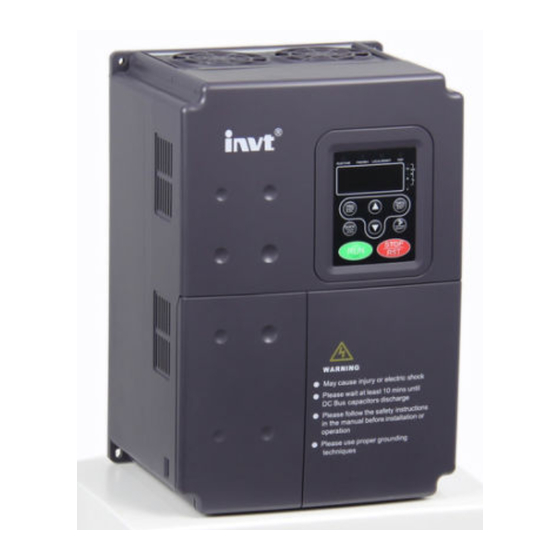
CHV Series Close loop Vector
Control Inverter
Operation Manual
Thank you very much for your buying CHV series close loop vector control
inverter.
Before use, please read this manual thoroughly to ensure proper usage. Keep
this manual at an easily accessible place so that can refer anytime as necessary.
Advertisement
Table of Contents

Subscribe to Our Youtube Channel
Related Manuals for INVT CHV Series


Summary of Contents for INVT CHV Series
- Page 1 CHV Series Close loop Vector Control Inverter Operation Manual Thank you very much for your buying CHV series close loop vector control inverter. Before use, please read this manual thoroughly to ensure proper usage. Keep this manual at an easily accessible place so that can refer anytime as necessary.
- Page 3 Safety Precautions Please read this operation manual carefully before installation, operation, maintenance or inspection. In this manual, the safety precautions were sorted to “WARNING” or “CAUTION”. Indicates a potentially hazardous situation which, if not WARNING avoided, will result in death or serious injury. Indicates a potentially hazardous situation which, if not CAUTION avoided, will result in minor or moderate injury and...
-
Page 4: Table Of Contents
TABLE OF CONTENTS TABLE OF CONTENTS.....................II LIST OF FIGURES......................IV 1. INTRODUCTION ......................1 1.1 Technology Features ..................1 1.2 Description of Name Plate ..................2 1.3 Selection Guide ....................3 1.4 Parts Description ....................4 1.5 Description of Extension Card ................6 1.6 External Dimension.....................8 2. - Page 5 5.1 Operating Keypad Description................34 5.1.1 Keypad schematic diagram..............34 5.1.2 Button function description..............34 5.1.3 Indicator light description ............... 35 5.2 Operation Process ....................36 5.2.1 Parameter setting................... 36 5.2.2 Shortcut menu setting ................37 5.2.3 Shortcut menu operation................ 37 5.2.4 Fault reset ....................38 5.2.5 Motor parameter autotune..............
-
Page 6: List Of Figures
LIST OF FIGURES Figure 1.1 Nameplate of inverter................. 2 Figure 1.2 Parts of inverter (15kw and below)............. 4 Figure 1.3 Parts of inverters (18.5KW and above)............5 Figure1.4 Dimensions (15kW and below)……………………………………………7 Figure 1.5 Dimensions (18.5~110kW)................. 8 Figure 1.6 Dimensions (132~315kW). - Page 7 Figure 6.1 Reference frequency diagram..............45 Figure 6.2 Acceleration and Deceleration time............46 Figure 6.3 Effect of carrier frequency................ 47 Figure 6.4 Starting diagram..................50 Figure 6.5 S curve diagram..................52 Figure 6.6 DC braking diagram.................. 53 Figure 6.7 FWD/REV dead time diagram.
- Page 8 Figure 6.33 Simple PLC operation diagram............... 92 Figure 6.34 Multi-steps speed operation diagram............ 94 Figure 6.35 Motor overload protection curve............. 97 Figure 6.36 Overload pre-warning schematic diagram..........98 Figure 6.37 Over-voltage stall function..............99 Figure 6.38 Over-current stall function..............100...
-
Page 9: Introduction
Introduction 1. INTRODUCTION 1.1 Technology Features ● Input & Output ◆Input Voltage Range: 1140/690/380/220V±15% ◆Input Frequency Range: 47~63Hz ◆Output Voltage Range: 0~rated input voltage ◆Output Frequency Range: 0~400Hz ● I/O Features ◆ Programmable Digital Input: Provide 5 terminals which can accept ON-OFF inputs, and 1 terminal which can accept high speed pulse input (HDI1). -
Page 10: Description Of Name Plate
◆ Up to 29 fault protections: Protect from over current, over voltage, under voltage, over temperature, phase failure, over load etc. 1.2 Description of Name Plate Company name SHENZHEN INVT ELECTRIC CO.,LTD Model number MODEL:CHV100-045G-4 SPEC:V1 Power POWER:45kW ±... -
Page 11: Selection Guide
Introduction 1.3 Selection Guide Rated Power Rated Input Rated Output Model No. Size (kW) Current (A) Current (A) 3AC 380V ±15% CHV100-1R5G-4 CHV100-2R2G-4 CHV100-004G-4 CHV100-5R5G-4 CHV100-7R5G-4 CHV100-011G-4 CHV100-015G-4 CHV100-018G-4 18.5 CHV100-022G-4 CHV100-030G-4 CHV100-037G-4 CHV100-045G-4 CHV100-055G-4 CHV100-075G-4 CHV100-090G-4 CHV100-110G-4 CHV100-132G-4 CHV100-160G-4 CHV100-185G-4 CHV100-200G-4 CHV100-220G-4... -
Page 12: Parts Description
Introduction 1.4 Parts Description Figure 1.2 Parts of inverter (15kw and below). -
Page 13: Figure 1.3 Parts Of Inverters (18.5Kw And Above)
Introduction Figure 1.3 Parts of inverters (18.5KW and above). -
Page 14: Description Of Extension Card
Introduction 1.5 Description of Extension Card Thanks to advanced modular design, CHV series inverters can achieve specific functionality by using extension card to meet customer demand. This feature is useful to enhance applicability and flexibility of CHV series inverter. For details, please refer to operation manual of extension card. - Page 15 Introduction Extension Card Description Offer RS232 and RS485 dual physical communication interface RS232 adopts standard DB9 master seat. 3-hole RS485 interface, two communication mode can be switched by short-connecting module. Receive high-speed pulse from encoder to realize high- accuracy close-loop vector control. Both push-and-pull input and open-circuit collector input.
-
Page 16: External Dimension
Introduction 1.6 External Dimension Figure1.4 Dimensions (15kW and below). Figure 1.5 Dimensions (18.5~110kW). Figure 1.6 Dimensions (132~315kW). -
Page 17: Figure 1.7 Dimensions (350Kw~630Kw)
Introduction Figure 1.7 Dimensions (350kw~630KW). Installation Power (mm) (mm) (mm) (mm) (mm) Size Hole (kW) Installation (mm) External Dimension Dimension 1.5~5.5 147.5 237.5 7.5~15 305.5 18.5~30 454.5 37~55 564.5 75~110 738.5 H(without 1233 1275 13.0 base) 132~185 H(with — — 1490 —... -
Page 18: Unpacking Inspection
Unpacking Inspection 2. UNPACKING INSPECTION CAUTION ● Never install or operate any inverter that is damaged or missing components. Doing so can result in injury. Check the following items when unpacking the inverter, 1. Inspect the entire exterior of the Inverter to see if there are any scratches or other damage resulting from shipping. -
Page 19: Disassemble And Installation
Disassemble and Installation 3. DISASSEMBLE AND INSTALLATION WARNING ● Any untrained person working on any parts/systems of inverter or any rule in the “Warning” being violated, that will cause severe injury or property damage. Only licensed person, who has been trained on design, installation, commissioning and operation of inverter, is permitted to operate this equipment. -
Page 20: Environmental Requirement
Disassemble and Installation 3.1 Environmental Requirement 3.1.1 Temperature Environment temperature range: -10°C ~ +40°C. Inverter will be derated if ambient temperature exceeds 40°C. 3.1.2 Humidity Less than 95% RH, without dewfall. 3.1.3 Altitude Inverter can output the rated power when installed with altitude of lower than 1000m. It will be derated when the altitude is higher than 1000m. -
Page 21: Installation Space
Disassemble and Installation 3.2 Installation Space Figure 3.2 Safety space. deflector Figure 3.3 Installation of multiple inverters. Notice: Add the air deflector when apply the up-down installation. -
Page 22: Dimensions Of External Keypad
Disassemble and Installation 3.3 Dimensions of External Keypad Figure 3.4 Dimension of small keypad. Figure 3.5 Dimension of big keypad. 3.4 Disassembly Figure 3.6 Disassembly of plastic cover. -
Page 23: Figure 3.7 Disassembly Of Metal Plate Cover
Disassemble and Installation Figure 3.7 Disassembly of metal plate cover. Figure 3.8 Open inverter cabinet. -
Page 24: Wiring
Wiring 4. WIRING WARNING ● Wiring must be performed by an authorized person qualified in electrical work. ● Do not test the insulation of cable that connects the inverter with high-voltage insulation testing devices. ● Can not install the inverter until discharged completely after the power supply is switched off for 10 minutes. -
Page 25: Connections Of Peripheral Devices
Wiring 4.1 Connections of Peripheral Devices Figure 4.1 Connections of peripheral devices. -
Page 26: Terminal Configuration
Wiring 4.2 Terminal Configuration 4.2.1 Main Circuit Terminals (380VAC) POWER MOTOR Figure 4.2 Main circuit terminals (1.5~5.5kW). (+) PB POWER MOTOR Figure 4.3 Main circuit terminals (7.5~15kW). P1 (+) POWER MOTOR Figure 4.4 Main circuit terminals (18.5~110kW). POWER MOTOR Figure 4.5 Main circuit terminals (132~315kW). -
Page 27: Control Circuit Terminals
Wiring Main circuit terminal functions are summarized according to the terminal symbols in the following table. Wire the terminal correctly for the desired purposes. Terminal Description Terminals of 3 phase AC input R、S、T (+)、(-) Spare terminals of external braking unit (+)、PB Spare terminals of external braking resistor P1、(+) -
Page 28: Typical Wiring Diagram
Wiring 4.3 Typical Wiring Diagram Figure4. 8 Wiring diagram. Notice: Inverters between 18.5KW and 90KW have built-in DC reactor which is used to improve power factor. For inverters above 110KW, it is recommended to install DC reactor between P1 and (+). The inverters below 18.5KW have build-in braking unit. -
Page 29: Specifications Of Breaker, Cable, Contactor And Reactor
Wiring 4.4 Specifications of Breaker, Cable, Contactor and Reactor 4.4.1 Specifications of breaker, cable and contactor Rated current of Circuit Input/output cable (mm Model No. contactor (A) breaker (A) (Coppery wire) (380V or 220V) 3AC 220V ±15% CHV100-0R7G-2 CHV100-1R5G-2 CHV100-2R2G-2 CHV100-004G-2 CHV100-5R5G-2 CHV100-7R5G-2... -
Page 30: Specifications Of Ac Input/Output And Dc Reactor
Wiring 4.4.2 Specifications of AC input/output and DC reactor AC Input reactor AC Output reactor DC reactor Model No. Current Inductance Current Inductance Current Inductance (A) (mH) (A) (mH) (A) (mH) 3AC 380V ±15% CHV100-1R5G-4 - - CHV100-2R2G-4 - - CHV100-004G-4 -... -
Page 31: Specification Of Braking Resistor
Wiring 4.4.3 Specification of braking unit and braking resistor Braking resistor Braking unit Model No. (100% braking torque) Order No. Quantity Specification Quantity 3AC 220V ±15% 138Ω/150W CHV100-1R5G-2 91Ω/220W CHV100-2R2G-2 Build-in 52Ω/400W CHV100-004G-2 37.5Ω/550W CHV100-5R5G-2 27.5Ω/750W CHV100-7R5G-2 19Ω/1100W CHV100-011G-2 13.6Ω/1500W CHV100-015G-2 DBU-055-2 12Ω/1800W... -
Page 32: Wiring The Main Circuits
Wiring CHV100-110G-4 CHV100-132G-4 DBU-160-4 4Ω/30000W CHV100-160G-4 CHV100-185G-4 DBU-220-4 3Ω/40000W CHV100-200G-4 CHV100-220G-4 CHV100-250G-4 DBU-315-4 CHV100-280G-4 3Ω/40000W CHV100-315G-4 Notice: 1. Above selection is based on following condition: 700V DC braking voltage threshold, 100% braking torque and 10% usage rate. 2. Parallel connection of braking unit is helpful to improve braking capability. 3. -
Page 33: Wiring For Inverter
Wiring be installed at the input side. It can also prevent rectifier from sudden variation of power voltage or harmonic generated by phase-control load. Input EMC filter The surrounding device may be disturbed by the cables when the inverter is working. EMC filter can minimize the interference. -
Page 34: Wiring At Motor Side Of Main Circuit
Wiring Notice: Be sure that the electric polarity of (+) (-) terminals is right; it is not allowed to connect (+) with (-) terminals directly, Otherwise damage or fire could occur. 4.5.3 Wiring at motor side of main circuit Output Reactor When the distance between inverter and motor is more than 50m, inverter may be tripped by over-current protection frequently because of the large leakage current resulted from the parasitic capacitance with ground. -
Page 35: Wiring Of Common Dc Bus
Wiring Figure 4.11 Wiring of regenerative unit. 4.5.5 Wiring of Common DC bus Common DC bus method is widely used in the paper industry and chemical fiber industry which need multi-motor to coordinate. In these applications, some motors are in driving status while some others are in regenerative braking (generating electricity) status. -
Page 36: Ground Wiring (Pe)
Wiring Figure 4.12 Wiring of common DC bus. Notice: Two inverters must be the same model when connected with Common DC bus method. Be sure they are powered on at the same time. 4.5.6 Ground Wiring (PE) In order to ensure safety and prevent electrical shock and fire, terminal PE must be grounded with ground resistance. -
Page 37: Control Circuit Terminals
Wiring 4.6.2 Control circuit terminals Terminal Description ON-OFF signal input, optical coupling with PW and COM. S1~S5 Input voltage range: 9~30V Input impedance: 3.3kΩ High speed pulse or ON-OFF signal input, optical coupling with PW and COM. HDI1(HDI2) Pulse input frequency range: 0~50kHz Input voltage range: 9~30V Input impedance: 1.1kΩ... -
Page 38: Jumper On Control Board
Wiring 4.6.3 Jumper on control board Jumper Description It is prohibited to be connected together, otherwise it will cause J2, J4, J5 inverter malfunction. Do not change factory default connection of J13 (marked with ATX) J13, J14 and J14 (marked with ARX), otherwise it will cause communication malfunction. -
Page 39: Emc Features Of Inverter
Wiring 4.7.2 EMC features of inverter Like other electric or electronic devices, inverter is not only an electromagnetic interference source but also an electromagnetic receiver. The operating principle of inverter determines that it can produce certain electromagnetic interference noise. And the same time inverter should be designed with certain anti-jamming ability to ensure the smooth working in certain electromagnetic environment. - Page 40 Wiring 4.7.3.2 Site wiring Power supply wiring: the power should be separated supplied from electrical transformer. Normally it is 5 core wires, three of which are fire wires, one of which is the neutral wire, and one of which is the ground wire. It is strictly prohibitive to use the same line to be both the neutral wire and the ground wire Device categorization: there are different electric devices contained in one control cabinet, such as inverter, filter, PLC and instrument etc, which have different ability of...
- Page 41 Wiring wire, can not only flow into inverter system but also other devices. It also can make leakage current circuit breaker, relay or other devices malfunction. The value of line-to-line leakage current, which means the leakage current passing through distributed capacitors of input output wire, depends on the carrier frequency of inverter, the length and section areas of motor cables.
-
Page 42: Operation
Operation 5. OPERATION 5.1 Operating Keypad Description 5.1.1 Keypad schematic diagram Figure 5.1 Keypad schematic diagram. 5.1.2 Button function description Button Name Description Programming Entry or escape of first-level menu. Enter Key Progressively enter menu and confirm parameters. UP Increment Progressively increase data or function codes. -
Page 43: Indicator Light Description
Operation Button Name Description Run Key Start to run the inverter in keypad control mode. In running status, restricted by P7.04, can be used to stop the inverter. STOP/RESET When fault alarm, can be used to reset the inverter without any restriction. Determined by Function Code P7.03: 0: Jog operation 1: Switch between forward and reverse... -
Page 44: Operation Process
Operation 5.1.3.3 Digital Display Have 5 digit LED , which can display all kinds of monitoring data and alarm codes such as reference frequency, output frequency and so on. 5.2 Operation Process 5.2.1 Parameter setting Three levels of menu are: Function code group (first-level);... -
Page 45: Shortcut Menu Setting
Operation This function code is not modifiable parameter, such as actual detected parameter, operation records and so on; This function code is not modifiable in running status, but modifiable in stop status. 5.2.2 Shortcut menu setting Shortcut menu, in which parameters in common use can be programmed, provides a quick way to view and modify function parameters. -
Page 46: Fault Reset
5.2.6 Password setting CHV series inverter offers user’s password protection function. When P7.00 is set to be nonzero, it will be the user’s password, and After exiting function code edit mode, it will become effective after 1 minute. If pressing the PRG/ESC again to try to access the function code edit mode, “-----”will be displayed, and the operator must input correct... -
Page 47: Running State
Operation 5.3 Running State 5.3.1 Power-on initialization Firstly the system initializes during the inverter power-on, and LED displays “8888”. After the initialization is completed, the inverter is on stand-by status. 5.3.2 Stand-by At stop or running status, parameters of multi-status can be displayed. Whether or not to display this parameter can be chosen through Function Code P7.06 (Running status display selection ) and P7.07 (Stop status display selection) according to binary bits, the detailed description of each bit please refer the function code description of P7.06 and... -
Page 48: Quick Start
Operation 5.4 Quick Start Start Set rated parameter of Select control mode motor (P2.01~P2.05) Set P0.00 Vector control V/F control Motor parameter autotuning Select run command source Set P0.01 Select frequency command source Set P0.03, P0.04, P0.05, P0.06 Set starting frequency P1.01 Set ACC time P0.11 and DEC time P0.12 Start to run and check... -
Page 49: Detailed Function Description
Detailed Function Description 6. DETAILED FUNCTION DESCRIPTION 6.1 P0 Group--Basic Function Function Setting Factory Name Description Code Range Setting Speed 0:Sensorless vector control P0.00 control 1:Vector control With PG mode 2:V/F control 0: Sensorless vector control: It is widely used for the application which requires high torque at low speed, higher speed accuracy, and quicker dynamic response, such as machine tool, injection molding machine, centrifugal machine and wire-drawing machine, etc. - Page 50 Detailed Function Description key QUICK/JOG is set as FWD/REV switching function (P7.03 is set to be 1), it will be used to change the rotating orientation. In running status, pressing RUN and STOP/RST in the same time will cause the inverter coast to stop. 1: Terminal (LED flickering) The operation, including forward run, reverse run, forward jog, reverse jog etc.
- Page 51 Detailed Function Description Function Setting Factory Name Description Code Range Setting 0: Keypad 1: AI1 2. AI3 Frequency 3: HDI1 P0.03 A command 4:Simple PLC source 5. Multi-Step speed 6: PID 7: Communication 0: Keypad: Please refer to description of P0.10 1: AI1 2: AI3 The reference frequency is set by analog input.
- Page 52 Detailed Function Description 6: PID The reference frequency is the result of PID adjustment. For details, please refer to description of P9 group. 7: Communication The reference frequency is set through RS485. For details, please refer to operation manual of communication card. Function Setting Factory...
-
Page 53: Figure 6.1 Reference Frequency Diagram
Detailed Function Description Reference frequency = reference frequency A + reference frequency B. 3: Both Frequency command source A and B are active. Reference frequency = Max (reference frequency A, reference frequency B). Notice: The frequency command source can be selected not only P0.06 but also by multifunctional terminals. -
Page 54: Figure 6.2 Acceleration And Deceleration Time
Detailed Function Description Function Factory Name Description Setting Range Code Setting Lower frequency P0.09 0.00Hz~ P0.08 0.00~P0.08 0.00Hz limit Notice: Lower frequency limit should not be greater than upper frequency limit (P0.08). If frequency reference is lower than P0.09, the action of inverter is determined by P1.14. -
Page 55: Figure 6.3 Effect Of Carrier Frequency
P0.11 and P0.12 respectively. The actual acceleration (deceleration) time = P0.11 (P0.12) * reference frequency/P0.07. CHV series inverter has 4 groups of acceleration and deceleration time. 1st group: P0.11, P0.12 2nd group: P8.00, P8.01 3rd group: P8.02, P8.03... - Page 56 Detailed Function Description Carrier frequency Factory Highest Carrier Lowest Carrier Setting Frequency( kHz ) Frequency( kHz ) Model ( kHz ) G Model: 1.5kW~11kW G Model: 15kW~55kW G Model: 75kW~630kW Carrier frequency will affect the noise of motor and the EMI of inverter. If the carrier frequency is increased, it will cause better current wave, less harmonic current and lower noise of motor.
- Page 57 Detailed Function Description 0: No action: Forbidding autotuning. 1: Rotation autotuning: Do not connect any load to the motor when performing autotuning and ensure the motor is in static status. Input the nameplate parameters of motor (P2.01~P2.05) correctly before performing autotuning. Otherwise the parameters detected by autotuning will be incorrect;...
-
Page 58: P1 Group--Start And Stop Control
Detailed Function Description 6.2 P1 Group--Start and Stop Control Function Setting Factory Name Description Code Range Setting 0: Start directly Start P1.00 1: DC braking and start Mode 2: Speed tracking and start 0: Start directly: Start the motor at the starting frequency determined by P1.01. 1: DC braking and start: Inverter will output DC current firstly and then start the motor at the starting frequency. - Page 59 Detailed Function Description Function Setting Factory Name Description Code Range Setting DC Braking P1.03 0.0~150.0% 0.0~150.0 0.0% current before start DC Braking time P1.04 0.0~50.0s 0.0~50.0 0.0s before start When inverter starts, it performs DC braking according to P1.03 firstly, then start to accelerate after P1.04.
-
Page 60: Figure 6.5 S Curve Diagram
Detailed Function Description Figure 6.5 S curve diagram. Function Factory Name Description Setting Range Code Setting 0:Deceleration to stop P1.08 Stop Mode 1:Coast to stop 0: Deceleration to stop When the stop command takes effect, the inverter decreases the output frequency according to P1.05 and the selected acceleration/deceleration time till stop. -
Page 61: Figure 6.6 Dc Braking Diagram
Detailed Function Description DC braking time: The time used to perform DC braking. If the time is 0, the DC braking will be invalid. Figure 6.6 DC braking diagram. Function Factory Name Description Setting Range Code Setting Dead time of P1.13 0.0~3600.0s 0.0~3600.0... -
Page 62: P2 Group--Motor Parameters
Detailed Function Description Function Setting Factory Name Description Code Range Setting 0: Running at the lower Action when running frequency limit P1.14 frequency is less than 1: Stop lower frequency limit 2: Stand-by 0: Running at the lower frequency limit (P0.09): The inverter runs at P0.09 when the running frequency is less than P0.09. - Page 63 Detailed Function Description Function Factory Name Description Setting Range Code Setting Motor rated P2.01 0.01Hz~P0.07 0.01~P0.07 50.00Hz frequency Motor rated P2.02 0~36000rpm 0~36000 1460rpm speed Motor rated Depend on P2.03 0~3000V 0~3000 voltage model Motor rated Depend on P2.04 0.1~2000.0A 0.1~2000.0 current model...
-
Page 64: P3 Group--Vector Control
Detailed Function Description 6.4 P3 Group--Vector Control Function Setting Factory Name Description Code Range Setting P3.00 ASR proportional gain K 0~100 0~100 P3.01 ASR integral time K 0.01~10.00s 0.01~10.00 0.50s P3.02 ASR switching point 1 0.00Hz~P3.05 0.00~P3.05 5.00Hz P3.03 ASR proportional gain K 0~100 0~100 P3.04... - Page 65 Detailed Function Description The system's dynamic response can be faster if the proportion gain K is increased; However, if K is too large, the system tends to oscillate. The system dynamic response can be faster if the integral time K is decreased;...
- Page 66 Detailed Function Description P3.10 defines the number of pulse per cycle of PG or encoder. Notice: When P0.00 is set to be 1, P3.10 must be set correctly according to the encoder parameter, otherwise the motor will run abnormally. If the motor still run abnormally when P3.10 has been set correctly, please change the PG direction (P3.11).
-
Page 67: P4 Group --V/F Control
Detailed Function Description Notice: When running at torque control mode, the acceleration time has nothing to do with P0.11. The 100% of torque setting is corresponding to 100% of P3.14 (Torque limit). For example, if torque setting source is keypad (P3.12=1), P3.13=80% and P3.14=90%, then Actual torque setting = 80% (P3.13) * 90% (P3.14) = 72%. -
Page 68: Figure 6.11 Torque Boost Diagram
Detailed Function Description Torque boost will take effect when output frequency is less than cut-off frequency of torque boost (P4.02). Torque boost can improve the torque performance of V/F control at low speed. The value of torque boost should be determined by the load. The heavier the load, the larger the value. -
Page 69: Figure 6.12 V/F Curve Setting Diagram
Detailed Function Description Figure 6.12 V/F curve setting diagram. Function Setting Factory Name Description Code Range Setting V/F slip P4.09 0.00~10.00Hz 0.00~10.00 0.0Hz compensation The motor’s slip changes with the load torque, which results in the variance of motor speed. The inverter’s output frequency can be adjusted automatically through slip compensation according to the load torque. -
Page 70: P5 Group--Input Terminals
Detailed Function Description When P4.11 is set to be 1, while there is a light load, it will reduce the inverter output voltage and saves energy. Function Setting Factory Name Description Code Range Setting FWD/REV enable 0: Disabled P4.12 option when power on 1: Enabled Notice: This function only takes effect if run command source is terminal control. - Page 71 Detailed Function Description Function Setting Factory Name Description Code Range Setting Programmable P5.05 S4 Terminal function 0~55 multifunction terminal Programmable P5.06 S5 Terminal function 0~55 multifunction terminal HDI1 terminal Programmable P5.07 0~55 function multifunction terminal HDI2 terminal Programmable P5.08 0~55 function multifunction terminal Programmable...
- Page 72 Detailed Function Description Setting Function Description value The reference frequency of inverter can be adjusted by UP command and DOWN command. Up command DOWN command Clear UP/DOWN Use this terminal to clear UP/DOWN setting. Please refer to description of P0.02. Switch between A and B...
- Page 73 Detailed Function Description Setting Function Description value 4 groups of ACC/DEC time can be selected by the combination of these two terminals. ACC/DEC ACC/DEC ACC/DEC time time time ACC/DEC time selection1 selection 2 selection1 ACC/DEC time 0 (P0.11、P0.12) ACC/DEC time 1 (P8.00、P8.01) ACC/DEC ACC/DEC time 2...
- Page 74 Detailed Function Description Setting Function Description value Combine with FWD/REV operation to be 3-wire jog control. 3-wire jog control Command Forward running Reverse running Forward jogging Reverse jogging 54~55 Reserved Reserved Function Setting Factory Name Description Code Range Setting P5.12 ON-OFF filter times 1~10 1~10...
-
Page 75: Figure 6.13 2-Wire Control Mode 1
Detailed Function Description Run command Stop Stop Figure 6.13 2-wire control mode 1. 1: 2-wire control mode 2: START/STOP command is determined by FWD terminal. Run direction is determined by REV terminal. Run command Stop Stop Figure 6.14 2-wire control mode 2. 2: 3-wire control mode 1: SB1: Start button. -
Page 76: Figure 6.16 3-Wire Control Mode 2
Detailed Function Description Figure 6.16 3-wire control mode 2. Notice: When 2-wire control mode is active, the inverter will not run in following situation even if FWD/REV terminal is enabled: Coast to stop (press RUN and STOP/RST at the same time). Stop command from serial communication. -
Page 77: Figure 6.17 Relationship Between Ai And Corresponding Setting
Detailed Function Description Figure 6.17 Relationship between AI and corresponding setting. Function Factory Name Description Setting Range Code Setting P5.20 AI2 lower limit 0.00V~10.00V 0.00~10.00 0.00V AI2 lower limit P5.21 -100.0%~100.0% -100.0~100.0 0.0% corresponding setting P5.22 AI2 upper limit 0.00V~10.00V 0.00~10.00 5.00V AI2 upper limit... - Page 78 Detailed Function Description Please refer to description of AI1. Notice: When AI2 is set as 0~20mA current input, the corresponding voltage range is 0~5V. Function Setting Factory Name Description Code Range Setting 0: Reference input HDI1 function P5.35 1: Counter input selection 2: Length input HDI2 function...
-
Page 79: P6 Group -- Output Terminals
Detailed Function Description 6.7 P6 Group -- Output Terminals Function Setting Factory Name Description Code range Setting 0: High-speed pulse output P6.00 selection 1: ON-OFF output 0: High-speed pulse output: The maximum pulse frequency is 50.0 kHz. Please refer to description of P6.09. - Page 80 Detailed Function Description Setting Function Description Value Frequency Please refer to description of P8.27. reached Zero speed ON: The running frequency of inverter is zero. running Preset count Please refer to description of P8.22. value reached Specified count Please refer to description of P8.23. value reached Length reached ON: Actual length (P8.20) reach the value of P8.19.
- Page 81 Detailed Function Description Setting Function Range Value Running frequency 0~maximum frequency (P0.07) Reference frequency 0~ maximum frequency (P0.07) Motor speed 0~2* rated synchronous speed of motor Output current 0~2* inverter rated current Output voltage 0~2* inverter rated voltage Output power 0~2* rated power Output torque 0~2*rated torque...
-
Page 82: Figure 6.18 Relationship Between Ao And Corresponding Setting
Detailed Function Description These parameters determine the relationship between analog output voltage/current and the corresponding output value. When the analog output value exceeds the range between lower limit and upper limit, it will output the upper limit or lower limit. When AO is current output, 1mA is corresponding to 0.5V. -
Page 83: P7 Group --Display Interface
Detailed Function Description 6.8 P7 Group --Display Interface Function Factory Name Description Setting Range Code Setting P7.00 User password 0~65535 0~65535 The password protection function will be valid when set to be any nonzero data. When P7.00 is set to be 00000, user’s password set before will be cleared and the password protection function will be disabled. - Page 84 Detailed Function Description Function Setting Factory Name Description Code Range Setting 0: Valid when keypad control (P0.01=0) 1: Valid when keypad or STOP/RST terminal control (P0.01=0 or function P7.04 selection 2: Valid when keypad or communication control (P0.01=0 or 2) 3: Always valid Notice: The value of P7.04 only determines the STOP function of STOP/RST.
- Page 85 Detailed Function Description P7.06 defines the parameters that can be displayed by LED in running status. If Bit is 0, the parameter will not be displayed; If Bit is 1, the parameter will be displayed. Press 》 /SHIFT to scroll through these parameters in right order . Press DATA/ENT + QUICK/JOG to scroll through these parameters in left order.
- Page 86 Detailed Function Description BIT7 BIT6 BIT5 BIT4 BIT3 BIT2 BIT1 BIT0 Output Input DC bus Reference PID preset terminal terminal feedback voltage frequency status status BIT15 BIT14 BIT13 BIT12 BIT11 BIT10 BIT9 BIT8 Step No. of HDI2 HDI1 Length Reserved Reserved PLC or value frequency...
-
Page 87: P8 Group --Enhanced Function
Detailed Function Description Function Setting Factory Name Description Code Range Setting Output frequency P7.16 Output frequency at current fault. at current fault Output current at P7.17 Output current at current fault. current fault DC bus voltage at P7.18 DC bus voltage at current fault. current fault This value records ON-OFF input terminal... -
Page 88: Figure 6.20 Skip Frequency Diagram
Detailed Function Description For details, please refer to description of P0.11 and P0.12. Function Factory Name Description Setting Range Code Setting Jog reference 0.00~P0.07 0.00~ P0.07 5.00Hz P8.06 Jog acceleration time 0.0~3600.0 20.0s P8.07 0.0~3600.0s Jog deceleration time 0.0~3600.0 20.0s P8.08 0.0~3600.0s The meaning and factory setting of P8.07 and P8.08 is the same as P0.11 and P0.12. -
Page 89: Figure 6.21 Traverse Operation Diagram
Detailed Function Description Function Setting Factory Name Description Code range Setting Traverse 0.0~100.0 0.0% P8.12 0.0~100.0% amplitude 0.0~50.0 0.0% P8.13 0.0~50.0% Jitter frequency Rise time of 0.1~3600.0 5.0s P8.14 0.1~3600.0s traverse Fall time of 0.1~3600.0 5.0s P8.15 0.1~3600.0s traverse Traverse operation is widely used in textile and chemical fiber industry. The typical application is shown in following figure. - Page 90 Detailed Function Description Function Setting Factory Name Description Code Range Setting P8.16 Auto reset times 0: Disabled P8.17 Fault relay action 1: Enabled 0.1~100.0 1.0s P8.18 Reset interval 0.1~100.0s Auto reset function can reset the fault in preset times and interval. When P8.16 is set to be 0, it means “auto reset”...
-
Page 91: Figure 6.22 Timing Chart For Preset And Specified Count Reached
Detailed Function Description The count pulse input channel can be S1~S5 (≤200Hz) and HDI. If function of output terminal is set as preset count reached, when the count value reaches preset count value (P8.22), it will output an ON-OFF signal. Inverter will clear the counter and restart counting. -
Page 92: Figure 6.23 Fdt Level Diagram
Detailed Function Description Figure 6.23 FDT Level diagram. Function Setting Factory Name Description Code Range Setting 0.0~100.0% Frequency arrive P8.27 (maximum 0.0~100.0 0.0% detecting range frequency) When output frequency is within the detecting range of reference frequency, an ON-OFF signal will be output. Figure 6.24 Frequency arriving detection diagram. -
Page 93: Figure 6.25 Droop Control Diagram
Detailed Function Description Function Setting Factory Name Description Code Range Setting Droop P8.28 0.00~10.00Hz 0.00~10.00 0.00Hz control When several motors drive the same load, each motor's load is different because of the difference of motor's rated speed. The load of different motors can be balanced through droop control function which makes the speed droop along with load increasing. -
Page 94: Figure 6.26 Simple Water-Supply Function Logical Diagram
Detailed Function Description Above parameters are used to realize simple water supply control function which one inverter drives three pumps (one variable-frequency pump and two power-frequency pumps). The control logic is shown in the following figure. Figure 6.26 Simple water-supply function logical diagram. Notice: Delay time of start auxiliary motor and stop auxiliary motor are the same. -
Page 95: P9 Group --Pid Control
Detailed Function Description Notice: Factory setting is 380V if rated voltage of inverter is 220V. Factory setting is 700V if rated voltage of inverter is 380V. The value of P8.32 is corresponding to the DC bus voltage at rated input voltage. - Page 96 Detailed Function Description Function Setting Factory Name Description Code Range Setting 3: AI3 4: AI4 5: HDI1 6: HDI2 7: Communication 8: Simple PLC Keypad P9.01 0.0%~100.0% 0.0~100.0 0.0% PID preset 0: AI1 1: AI2 2: AI3 3: AI4 feedback 4: AI1-AI2 P9.02 5: AI3-AI4...
-
Page 97: Figure 6.28 Reducing Overshooting Diagram
Detailed Function Description Optimize the responsiveness by adjusting these parameters while driving an actual load. Adjusting PID control: Use the following procedure to activate PID control and then adjust it while monitoring the response. Enabled PID control (P0.03=6) Increase the proportional gain (Kp) as far as possible without creating oscillation. Reduce the integral time (Ti) as far as possible without creating oscillation. -
Page 98: Figure 6.30 Reducing Long-Cycle Oscillation Diagram
Detailed Function Description Reducing long-cycle oscillation If oscillation occurs with a longer cycle than the integral time setting, it means that integral operation is strong. The oscillation will be reduced as the integral time is lengthened. Figure 6.30 Reducing long-cycle oscillation diagram. Reducing short-cycle oscillation If the oscillation cycle is short and oscillation occurs with a cycle approximately the same as the differential time setting, it means that the differential operation is strong. -
Page 99: Figure 6.32 Relationship Between Bias Limit And Output Frequency
Detailed Function Description Sampling cycle T refers to the sampling cycle of feedback value. The PI regulator calculates once in each sampling cycle. The bigger the sampling cycle, the slower the response is. Bias limit defines the maximum bias between the feedback and the preset. PID stops operation when the bias is within this range. -
Page 100: Pa Group --Simple Plc And Multi-Step Speed Control
Detailed Function Description 6.11 PA Group --Simple PLC and Multi-step Speed Control Simple PLC function can enable the inverter change its output frequency and directions automatically according to preset running time. For multi-step speed function, the output frequency can be changed only by multi-step terminals. Notice: Simple PLC has 16 steps which can be selected. - Page 101 Detailed Function Description This parameter determines whether the running step and output frequency of simple PLC should be saved. If PA.01 is set to be 2, running step and output frequency will be saved when inverter stops, but will not be saved when inverter is power off Function Factory Name...
-
Page 102: Figure 6.34 Multi-Steps Speed Operation Diagram
Detailed Function Description Function Factory Name Description Setting Range Code Setting PA.26 Multi-step speed 12 -100.0~100.0% -100.0~100.0 0.0% PA.27 Step running time 0.0~6553.5s(h) 0.0~6553.5 0.0s PA.28 Multi-step speed 13 -100.0~100.0% -100.0~100.0 0.0% PA.29 Step running time 0.0~6553.5s(h) 0.0~6553.5 0.0s PA.30 Multi-step speed 14 -100.0~100.0% -100.0~100.0... - Page 103 Detailed Function Description Multi-step Multi-step Multi-step Multi-step Terminal speed speed speed speed Step reference1 reference2 reference3 reference4 Function Setting Factory Name Description Code Range Setting ACC/DEC time selection for step PA.34 0~65535 0~65535 ACC/DEC time selection for step PA.35 0~65535 0~65535 8~15 These parameters are used to determine the ACC/DEC time from one step to next step.
- Page 104 Detailed Function Description Function Step ACC/DEC ACC/DEC ACC/DEC ACC/DEC Binary Digit Code Time 0 Time 1 Time 2 Time 3 BIT1 BIT0 BIT3 BIT2 BIT5 BIT4 BIT7 BIT6 PA.35 BIT9 BIT8 BIT11 BIT10 BIT3 BIT12 BIT15 BIT14 For example: To set the acceleration time of following table: Step No.
-
Page 105: Pb Group -- Protection Parameters
Detailed Function Description 6.12 PB Group -- Protection Parameters Setting Factory Function Code Name Description Range Setting Input phase-failure 0: Disabled PB.00 protection 1: Enabled Output phase-failure 0: Disabled PB.01 protection 1: Enabled Notice: Please be cautious to set these parameters as disabled. Otherwise it may cause inverter and motor overheat even damaged. -
Page 106: Figure 6.36 Overload Pre-Warning Schematic Diagram
Detailed Function Description Notice: This parameter is normally used when rated power of inverter is greater than rated power of motor. Motor overload protection time: 60s with 200% of rated current. For details, please refer to above figure. Function Setting Factory Name Description... -
Page 107: Figure 6.37 Over-Voltage Stall Function
Detailed Function Description Function Factory Name Description Setting Range Code Setting Threshold of Pb.07 230.0V~600.0V 230.0~600.0 450.0V trip-free Decrease rate PB.08 0.00Hz~P0.07 0.00Hz~P0.07 0.00Hz of trip-free If PB.08 is set to be 0, the trip-free function is invalid. Trip-free function enables the inverter to perform low-voltage compensation when DC bus voltage drops below PB.07. -
Page 108: Figure 6.38 Over-Current Stall Function
Detailed Function Description Function Setting Factory Name Description Code Range Setting Over-current 0: Disabled PB.11 protection 1: Enabled Over-current stall PB.12 100~200% 100~200 160% threshold Frequency decrease PB.13 0.00~50.00Hz/s 0.00~50.00 1.00Hz/s rate During acceleration of inverter, the actual motor speed rise rate may lower than the output frequency rise rate because of too big load. -
Page 109: Pc Group --Serial Communication
Detailed Function Description 6.13 PC Group --Serial Communication For details, please refer to operation manual of serial communication card. 6.14 PD Group --Supplementary Function Function Setting Factory Name Description Code Range Setting 0: Keypad 1: AI1 2: AI2 Upper 3: AI3 PD.00 frequency limit 4: AI4... -
Page 110: Trouble Shooting
Trouble Shooting 7. TROUBLE SHOOTING 7.1 Fault and trouble shooting Fault Code Fault Type Reason Solution IGBT Ph-U 1. Acc/Dec time is too OUT1 1. Increase Acc/Dec fault short. time. 2. IGBT module fault. 2. Ask for support. OUT2 IGBT Ph-V fault 3. - Page 111 Trouble Shooting Fault Code Fault Type Reason Solution 1. Motor drive heavy load at low speed for a long 1. Select variable time. frequency motor. 2. Improper V/F curve 2. Check and adjust Motor overload 3. Improper motor’s V/F curve. overload protection 3.
- Page 112 Trouble Shooting Fault Code Fault Type Reason Solution 1. Wires or connectors of control board are loose Current 2. Hall sensor is 1. Check the wiring. detection fault damaged. 2. Ask for support. 3. Amplifying circuit is abnormal. 1. Set rated parameters 1.
-
Page 113: Common Faults And Solutions
Trouble Shooting 7.2 Common Faults and Solutions Inverter may have following faults or malfunctions during operation, please refer to the following solutions. No display after power on: Inspect whether the voltage of power supply is the same as the inverter rated voltage or not with multi-meter. -
Page 114: Maintenance
Maintenance 8. MAINTENANCE WARNING ● Maintenance must be performed according to designated maintenance methods. ● Maintenance, inspection and replacement of parts must be performed only by authorized personnel. ● After turning off the main circuit power supply, waiting for 10 minutes before performance maintenance or inspection. - Page 115 Maintenance Main inspections Criteria Items to be hecked Inspection Frequency Means/methods content smooth operation ⑴ point without vibration. ⑵ n ⑴ vibration ⑴ thermometer is working in good cooling and ⑵ Inverter comprehensive condition. Speed and air heating observation flow are normal. No noise ⑶...
-
Page 116: Periodic Maintenance
Maintenance 8.2 Periodic Maintenance Customer should check the drive every 3 months or 6 months according to the actual environment 1. Check whether the screws of control terminals are loose. If so, tighten them with a screwdriver; 2. Check whether the main circuit terminals are properly connected; whether the mains cables are over heated;... -
Page 117: List Of Function Parameters
List of Function parameters 9. LIST OF FUNCTION PARAMETERS Notice: PE group is factory reserved, users are forbidden to access these parameters. The column “Modify” determines the parameter can be modified or not. ○ “ ” indicates that this parameter can be modified all the time. “◎”indicates that this parameter cannot be modified during the inverter is running. - Page 118 List of Function Parameters Function Factory Name Description Modify LCD Display Code Setting 0:AI2 Frequency B FREQ P0.04 1:AI4 ◎ command source SOURCE B 2:HDI2 Scale of frequency 0: Maximum frequency FREQ B P0.05 ○ B command 1: Frequency A command SCALE 0: A 1: B...
- Page 119 List of Function parameters Function Factory Name Description Modify LCD Display Code Setting Hold time of P1.02 0.0~50.0s 0.0s ◎ HOLD TIME starting frequency DC Braking START BRAK P1.03 current before 0.0~150.0% 0.0% ◎ CURR start START BRAK DC Braking time P1.04 0.0~50.0s 0.0s...
- Page 120 List of Function Parameters Function Factory Name Description Modify LCD Display Code Setting Motor rated MOTOR P2.01 0.01Hz~P0.07 50.00Hz ◎ frequency RATE FREQ 1460 MOTOR P2.02 Motor rated speed 0~36000rpm ◎ RATE SPEED Depend MOTOR P2.03 Motor rated voltage 0~3000V ◎...
- Page 121 List of Function parameters Function Factory Name Description Modify LCD Display Code Setting ASR switching P3.05 P3.02~P0.07 10.00Hz ○ SWITCHPOIN point 2 ACR proportional P3.06 0~65535 ○ ACR P gain P P3.07 ACR integral gain I 0~65535 ○ ACR I Speed detection FEEDBACK P3.08...
- Page 122 List of Function Parameters Function Factory Name Description Modify LCD Display Code Setting Torque boost 0.0%~50.0% (motor rated BOOST P4.02 20.0% ◎ cut-off frequency) CUT-OFF P4.03 V/F frequency 1 0.00Hz~ P4.05 5.00Hz V/F FREQ 1 ◎ P4.04 V/F voltage 1 0.0%~100.0% 10.0% ◎...
- Page 123 List of Function parameters Function Factory Name Description Modify LCD Display Code Setting 8:Pause running S3 Terminal 9:External fault input P5.04 ◎ function 10:UP command FUNCTION 11:DOWN command 12:Clear UP/DOWN S4 Terminal 13:Switch between A and B P5.05 ◎ function FUNCTION 14:Switch between A and S5 Terminal...
- Page 124 List of Function Parameters Function Factory Name Description Modify LCD Display Code Setting P5.17 AI1 upper limit 0.00V~10.00V 10.00V ○ AI1 UP LIMIT P5.18 AI1 upper limit AI1 UP corresponding -100.0%~100.0% 100.0% ○ SETTING setting P5.19 AI1 filter time AI1 FILTER 0.00s~10.00s 0.10s ○...
- Page 125 List of Function parameters Function Factory Name Description Modify LCD Display Code Setting AI4 filter time AI4 FILTER P5.34 0.00s~10.00s 0.10s ○ constant TIME HDI1 function 0: Reference input HDI1 P5.35 ◎ selection 1: Counter input FUNCTION 2: Length input HDI2 function HDI2 3: Reserved...
- Page 126 List of Function Parameters Function Factory Name Description Modify LCD Display Code Setting HDO ON-OFF 4: Motor overload P6.03 ○ output selection SELECTION 5: Inverter overload 6: FDT reached Relay 1 output P6.04 ○ 7: Frequency reached selection SELECTION 8: Zero speed running 9: Preset count value Relay 2 output P6.05...
- Page 127 List of Function parameters Function Factory Name Description Modify LCD Display Code Setting AO2 LOW P6.14 AO2 lower limit 0.0%~100.0% 0.0% ○ LIMIT AO2 lower limit AO2 LOW P6.15 corresponding 0.00V ~10.00V 0.00V ○ OUTPUT output P6.16 AO2 upper limit 0.0%~100.0% 100.0% ○...
- Page 128 List of Function Parameters Function Factory Name Description Modify LCD Display Code Setting 0: Preferential to external keypad 1: Both display, only external Keypad display KEYPAD P7.05 key valid. ○ selection DISPLAY 2: Both display, only local key valid. 3: Both display and key valid. 1.Output frequency 2.Reference frequency 3.DC bus voltage...
- Page 129 List of Function parameters Function Factory Name Description Modify LCD Display Code Setting Rectifier module RECTIFIER P7.08 0~100.0℃ ● temperature TEMP IGBT module P7.09 0~100.0℃ ● IGBT TEMP temperature MCU software P7.10 Factory setting ● version VERSION DSP software P7.11 Factory setting ●...
- Page 130 List of Function Parameters Function Factory Name Description Modify LCD Display Code Setting 24: : EEPROM fault (EEP) 25: PID feedback fault (PIDE) 26: Brake unit fault (BCE) CURRENT P7.15 Latest fault type 27: Trial time reached(END) ● FAULT 28: LCD disconnected(LCD-E) 29: Clock chip fault(TI-E) 30: Reserved...
- Page 131 List of Function parameters Function Factory Name Description Modify LCD Display Code Setting Skip frequency SKIP FREQ P8.11 0.00~P0.07 0.00Hz ○ bandwidth RANGE 0.0~100.0% (with reference TRAV P8.12 Traverse amplitude 0.0% ○ to P0.10) AMPLITUDE P8.13 Jitter frequency 0.0~50.0% 0.0% ○...
- Page 132 List of Function Parameters Function Factory Name Description Modify LCD Display Code Setting Auxiliary motor1 MOTOR 1 P8.30 START/STOP 0.0~3600.0s 5.0s ○ DELAY delay time Auxiliary motor2 MOTOR 2 P8.31 START/STOP 0.0~3600.0s 5.0s ○ DELAY delay time Brake threshold P8.32 320.0~750.0V 700.0V ○...
- Page 133 List of Function parameters Function Factory Name Description Modify LCD Display Code Setting Proportional gain PROPORTIO P9.04 0.00~100.00 0.10 ○ (Kp) N GAIN INTEGRAL P9.05 Integral time (Ti) 0.01~10.00s 0.10s ○ TIME Differential time DIFFERENTI P9.06 0.00~10.00s 0.00s ○ (Td) A TIME SAMPLING P9.07...
- Page 134 List of Function Parameters Function Factory Name Description Modify LCD Display Code Setting MULTI-SPEE PA.08 Multi-step speed 3 -100.0~100.0% 0.0% ○ Step running RUNNING PA.09 0.0~6553.5s(h) 0.0s ○ time TIME 3 MULTI-SPEE PA.10 Multi-step speed 4 -100.0~100.0% 0.0% ○ Step running RUNNING PA.11 0.0~6553.5s(h)
- Page 135 List of Function parameters Function Factory Name Description Modify LCD Display Code Setting MULTI-SPEE PA.26 Multi-step speed 12 -100.0~100.0% 0.0% ○ D 12 Step running RUNNING PA.27 0.0~6553.5s(h) 0.0s ○ time TIME 12 MULTI-SPEE PA.28 Multi-step speed 13 -100.0~100.0% 0.0% ○...
- Page 136 List of Function Parameters Function Factory Name Description Modify LCD Display Code Setting Overload OL WARN PB.04 pre-warning 20.0%~150.0% 130.0% ○ CURR threshold 0: Always detect relative to motor rated current 1: Detect while constant speed relative to motor rated Overload current OL WARN...
- Page 137 List of Function parameters Function Factory Name Description Modify LCD Display Code Setting 0: RTU, 1 start bit, 8 data bits, no parity check, 1 stop bit. 1: RTU, 1 start bit, 8 data bits, even parity check, 1 stop bit. 2: RTU, 1 start bit, 8 data bits, odd parity check, 1 stop bit.
- Page 138 List of Function Parameters Function Factory Name Description Modify LCD Display Code Setting Communication COM DELAY PC.03 0~20ms ○ delay time TIME Communication 0.0(invalid) PC.04 0.0s ○ timeout delay 0.1~100.0s TIMEOUT 0: Enabled RESPONSE PC.05 Response action ○ 1: Disabled ACTION 0: Alarm and coast to stop 1: Not alarm and keep...
Need help?
Do you have a question about the CHV Series and is the answer not in the manual?
Questions and answers