Table of Contents
Advertisement
Quick Links
Advertisement
Table of Contents

Related Manuals for INVT Goodrive200A Series


Summary of Contents for INVT Goodrive200A Series
- Page 2 The vector control performance of Goodrive200A series VFD is as outstanding as that of the leading sophisticated VFDs in worldwide market. Its integrated speed and torque control can satisfy various application demands, in the meantime, its excellent anti-trip performance and strong adaptability to worse grid, temperature, humidity and dust guarantees its outstanding reliability and stability.
-
Page 3: Table Of Contents
GD200A series VFD Contents Contents Preface ............................i Contents ............................ii 1 Safety precautions ........................1 1.1 What this chapter contains ....................1 1.2 Safety definition ........................1 1.3 Warning symbols ......................... 1 1.4 Safety guidelines ......................... 2 1.4.1 Delivery and installation ..................... 2 1.4.2 Commission and running ................... - Page 4 GD200A series VFD Contents 4.3.5 Terminals of control circuit ..................23 4.3.6 Input /Output signal connection figure ..............25 4.4 Layout protection ......................26 4.4.1 Protecting the VFD and input power cable in short-circuit situations ......26 4.4.2 Protecting the motor and motor cable in short-circuit situations ........ 27 4.4.3 Protecting the motor against thermal overload ............
- Page 5 GD200A series VFD Contents 7.8 Simple PLC ........................107 7.9 Multi-step speed running ....................107 7.10 PID control ........................108 7.10.1 General steps of PID parameters setting: ............109 7.10.2 PID inching......................109 7.11 Pulse counter ........................ 110 8 Fault tracking .......................... 112 8.1 What this chapter contains ....................
- Page 6 GD200A series VFD Contents 9.6 Example of writing and reading ..................144 9.6.1 Example of reading command 03H ................ 144 9.6.2 Example of writing command 06H ................. 145 9.6.3 Example of continuous writing command 10H ............147 Appendix A Technical data ......................150 A.1 What this chapter contains ....................
- Page 7 C.8.3 Place the brake resistor ..................171 C.9 Other optional parts ......................172 Appendix D Further Information ....................174 D.1 Product and service inquiries ..................174 D.2 Feedback on INVT VFD manuals ..................174 D.3 Document library on the internet ..................174...
-
Page 8: Safety Precautions
GD200A series VFD Safety precautions 1 Safety precautions 1.1 What this chapter contains Read this manual carefully and follow all safety precautions before moving, installing, operating and servicing the variable-frequency drive (VFD). If ignored, physical injury or death may occur, or damage may occur to the devices. -
Page 9: Safety Guidelines
GD200A series VFD Safety precautions 1.4 Safety guidelines Only qualified electricians are allowed to operate on the VFD. Do not carry out any wiring and inspection or changing components when the power supply is applied. Ensure all input power supply is disconnected before wiring and checking and always wait for at least the time designated on the VFD or until the DC bus voltage is less than 36V. -
Page 10: Commission And Running
GD200A series VFD Safety precautions The leakage current of the VFD may be above 3.5mA during operation. Ground with proper techniques and ensure the grounding resistor is less than 10Ω. The conductivity of PE grounding conductor is the same as that of the phase conductor (with the same cross sectional area). -
Page 11: Scrap Treatment
GD200A series VFD Safety precautions Keep the VFD, parts and components away from combustible materials during maintenance and component replacement. Do not carry out any insulation voltage-endurance test on the VFD and do not measure the control circuit of the VFD by megameter. ... -
Page 12: Quick Start
4. Check whether the name plate of the VFD is consistent with the model identifier on the exterior surface of the packing box. If not, contact local dealers or INVT offices. 5. Check whether the accessories (including user's manual and control keypad) inside the packing box are complete. -
Page 13: Installation Confirmation
When the installation site altitude exceeds 1000m, derate 1% for every increase of 100m; when the installation site altitude exceeds 3000m, consult the local INVT dealer or office. 4. Check that the humidity of the actual usage site is below 90% and condensation is not allowed. -
Page 14: Product Overview
The chapter briefly describes the operation principle, product characteristics, layout, nameplate and type designation information. 3.2 Basic principles Goodrive200A series VFDs are wall, flange and floor mountable devices for controlling asynchronous AC inductance motors. The diagram below shows the main circuit diagram of the VFD. The rectifier converts three-phase AC voltage to DC voltage. -
Page 15: Product Specifications
GD200A series VFD Product overview 3. The 037G/045P and higher models can be installed with optional braking units and the braking unit and resistor are optional. 3.3 Product specifications Function Specification Input voltage (V) AC 3PH 380V(-15%)–440V(+10%) See Rated specifications. Input current (A) Input 50Hz or 60Hz... -
Page 16: Nameplate
63Hz Output: AC 3PH 0V-Uinput 75A/92A 0Hz-400Hz S/N: Made in China Shenzhen INVT Electric Co.,Ltd Figure 3-3 Nameplate Note: This is the example of the nameplate for the standard products, and CE\TUV\IP20 will be marked according to the actual situations. -
Page 17: Type Designation Key
GD200A series VFD Product overview 3.5 Type designation key The type designation contains information on the VFD. The user can find the type designation on the type designation label attached to the VFD or the simple nameplate. GD200A-011 G/015 P-4 ①... - Page 18 GD200A series VFD Product overview Constant torque Variable torque Output Input Output Output Input Output VFD model power current current power current current (kW) (kW) GD200A-160G/185P-4 GD200A-185G/200P-4 GD200A-200G/220P-4 GD200A-220G/250P-4 GD200A-250G/280P-4 GD200A-280G/315P-4 GD200A-315G/355P-4 GD200A-355G/400P-4 GD200A-400G-4 GD200A-450G-4 GD200A-500G-4 Note: 1. The input current of the 0R7G–315G/355P models is measured when the input voltage is 380V and no DC reactor and input/output reactor.
-
Page 19: Structure Diagram
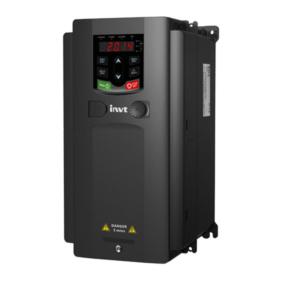
GD200A series VFD Product overview 3.7 Structure diagram Below is the VFD layout figure (taking the 030G/037P model for example). Figure 3-5 Product structure diagram Serial Name Illustration Keypad port Connect the keypad Upper cover Protect the internal parts and components Keypad See 5.4 Keypad operationfor detailed information See 8.8 Maintenance and hardware diagnostics for... -
Page 20: Installation Guidelines
GD200A series VFD Installation guidelines 4 Installation guidelines 4.1 What this chapter contains The chapter describes the mechanical installation and electric installation. Only qualified electricians are allowed to carry out what described in this chapter. Please operate as the instructions in chapter 1 Safety precautions. Ignoring these may cause physical injury or death or damage to the devices. -
Page 21: Installation Direction
The VFD should be installed on an upright position to ensure sufficient Installation direction cooling effect. Note: Goodrive200A series VFDs should be installed in a clean and ventilated environment according to enclosure classification. Cooling air must be clean, free from corrosive materials and electrically conductive dust. 4.2.2 Installation direction The VFD may be installed on the wall or in a cabinet. -
Page 22: Installation Manner
GD200A series VFD Installation guidelines 4.2.3 Installation manner The VFD can be installed in two different ways, depending on the frame size: a) Wall mounting (for the 315G/355P and lower models) b) Flange mounting (for the 200G/220P and lower models). Some need optional flange installation board. -
Page 23: Vertical Installation
GD200A series VFD Installation guidelines Warm air Cool air Figure 4-3 Parallel installation Note: Before installing the different size VFDs, please align their top position for the convenience of later maintenance. The minimum space of B, D and C is 100mm. 4.2.5 Vertical installation Wind board Wind board... -
Page 24: Tilt Installation
GD200A series VFD Installation guidelines 4.2.6 Tilt installation Figure 4-5 Tilt installation Note: Ensure the separation of the wind input and output channels in tilt installation for avoiding mutual impact. 4.3 Standard wiring 4.3.1 Wiring diagram of main circuit Braking resistor Output reactor Input... -
Page 25: Terminals Figure Of Main Circuit
GD200A series VFD Installation guidelines Braking resistor For 1PH 220V: optional Output reactor Input 3PH power Output reactor 018G/022P~030G/037P filter Input 50/60Hz filter Fuse Figure 4-7 Main circuit wiring diagram for the 018G/022P–030G/037P models Braking unit DC reactor Braking resistor For 1PH 220V: optional Output reactor... - Page 26 GD200A series VFD Installation guidelines Figure 4-10 Main circuit terminals for the 7R5G/011P–015G/018P models Figure 4-11 Main circuit terminals for the 018G/022P model Figure 4-12 Main circuit terminals for the 022G/030P–030G/037P models Figure 4-13 Main circuit terminals for the 037G/045P–055G/075P models -19-...
- Page 27 GD200A series VFD Installation guidelines Figure 4-14 Main circuit terminals for the 075G/090P–110G/132P models Figure 4-15 Main circuit terminals for the 132G/160P–200G/220P models Figure 4-16 Main circuit terminals for the 220G/250P–315G/355P models -20-...
- Page 28 GD200A series VFD Installation guidelines Figure 4-17 Main circuit terminals for the 355G/400P–500G models Terminal name For the Terminal Function For the 037G/045P and 030G/037P and higher models lower models 3-phase AC input terminals which are R, S, T Power input of the main circuit generally connected with the power supply.
-
Page 29: Wiring Of Terminals In Main Circuit
GD200A series VFD Installation guidelines Note: Do not use an asymmetrically constructed motor cable. If there is a symmetrically constructed grounding conductor in the motor cable in addition to the conductive shield, connect the grounding conductor to the grounding terminal at the VFD and motor ends. ... -
Page 30: Wiring Diagram Of Control Circuit
GD200A series VFD Installation guidelines 4.3.4 Wiring diagram of control circuit Multifunction input terminal 1 Multifunction input terminal 2 Multifunction input terminal 3 Analog output 0-10V/0-20mA Multifunction input terminal 4 Multifunction input terminal 5 Analog output 0-10V/0-20mA Multifunction input terminal 6 Multifunction input terminal 7 Multifunction input terminal 8 Open collector output... - Page 31 GD200A series VFD Installation guidelines Reserve AI 2 Figure 4-21 Control circuit terminals for the 018G/022P and higher models Note: the spare terminal is reserved and not be used. Terminal Description name 1. Switch output: 50mA/30V 2. Output frequency range: 0–50kHz +24V common terminal Common terminal of HDO and Y1, short-connected with COM in factory 1.Swtich capability: 50mA/30V...
-
Page 32: Input /Output Signal Connection Figure
GD200A series VFD Installation guidelines Terminal Description name Switch input 1 1. Internal impedance: 3.3kΩ Switch input 2 2. 12–30V voltage input is available Switch input 3 3. The terminal is the dual-direction input terminal Switch input 4 supporting both NPN and PNP Switch input 5 4. -
Page 33: Layout Protection
GD200A series VFD Installation guidelines +24V +24V +24V +24V +24V Internal power supply (NPN) External power supply (NPN) Figure 4-23 NPN modes If the signal is from PNP transistor, please set the U-shaped contact tag as below according to the used power supply. -
Page 34: Protecting The Motor And Motor Cable In Short-Circuit Situations
GD200A series VFD Installation guidelines 4.4.2 Protecting the motor and motor cable in short-circuit situations The VFD protects the motor and motor cable in a short-circuit situation when the motor cable is dimensioned according to the rated current of the VFD. No additional protection devices are needed. -
Page 35: Keypad Operation Procedure
Buttons, indicating lights and the screen as well as the methods to inspect, modify and set function codes by keypad Start 5.2 Keypad The keypad is used to control Goodrive200A series VFDs, read the state data and adjust parameters. Figure 5-1 Keypad Note: ... - Page 36 GD200A series VFD Keypad operation procedure Name Description LED off – the VFD will run in the forward direction FWD/REV LED on – the VFD will run in the reverse direction LED indicates keypad operation, terminal operation and remote communication control LED off –...
-
Page 37: Keypad Displaying
The keypad interface is standard configuration for the 015G/018P and Keypad interface lower models. 5.3 Keypad displaying The keypad displaying state of Goodrive200A series VFDs is divided into stopping state parameter, running state parameter, function code parameter editing state and fault alarm state and so on. DATA DATA... -
Page 38: How To Set The Password Of The Vfd
5.4.2 How to set the password of the VFD Goodrive200A series VFDs provides the user password protection function. When you set P07.00 to a non-zero value, the value is the user password. After you exit the function code editing interface, the password protection function is enabled within 1 minute. -
Page 39: How To Watch The Vfd State Through Function Codes
GD200A series VFD Keypad operation procedure 5.4.3 How to watch the VFD state through function codes Goodrive200A series VFDs provide group P17 as the state inspection group. Users can enter into P17 directly to watch the state. The units place is blinking... -
Page 40: Function Parameters
This chapter lists and describes the function parameters. Goodrive200A general series function parameters The function parameters of Goodrive200A series VFDs have been divided into 30 groups (P00–P29) according to the function, of which P18–P28 are reserved. Each function group contains certain function codes applying 3-level menus. -
Page 41: P00 Group Basic Functions
GD200A series VFD Function parameters that the users cannot modify the factory parameters by themselves, otherwise, if the parameter setting is incorrect, damage to the VFD may occur). If the password protection is unlocked, the user can modify the password freely and the VFD will work as the last setting one. When P07.00 is set to 0, the password can be canceled. - Page 42 0150G/018P and lower models; not available for P00.07 command the 018G/022P and higher models.) 2: Analog AI2 setting 3: Analog AI3 setting Set the frequency by analog input terminals. Goodrive200A series VFDs provide 3 channels analog input terminals as the standard -35-...
- Page 43 (function code P00.03) 4: High-speed pulse HDI setting The frequency is set by high-speed pulse terminals. Goodrive200A series VFDs provide 1 channel high speed pulse input as the standard configuration. The pulse frequency range is 0.00–50.00kHz.
- Page 44 GD200A series VFD Function parameters Function Default Name Description Modify code value P00.07 does not equal to 6, but the setting step can only be the 1–15 steps. The setting step is 0–15 if P00.06 P00.07 equals 6. 7: PID control setting The running mode of the VFD is process PID control when P00.06=7 or P00.07=7.
- Page 45 ACC time 1 speeds down from the max. output frequency to model 0Hz (P00.03). Goodrive200A series VFDs define four groups of ACC/DEC time which can be selected by P05. Depend The factory default ACC/DEC time of the VFD is ○...
- Page 46 GD200A series VFD Function parameters Function Default Name Description Modify code value Factory setting Model of carrier frequency 0R7G–011G/015P 8kHz 015G/018P–055G/075P 4kHz 075G/090P and higher 2kHz The advantage of high carrier frequency: ideal current waveform, little current harmonic wave and motor noise. The disadvantage of high carrier frequency: increasing the switch loss, increasing VFD temperature and the impact to the output capacity.
-
Page 47: P01 Group Start And Stop Control
GD200A series VFD Function parameters Function Default Name Description Modify code value 0: Invalid 1: Valid during the whole procedure AVR function ○ P00.16 The auto-adjusting function of the VFD can cancel selection the impact on the output voltage of the VFD because of the bus voltage fluctuation. - Page 48 GD200A series VFD Function parameters Function Default Name Description Modify code value cases where reverse rotation may occur to the big inertia load during starting. Note: This function is available for the 004G/5R5P and higher models. Starting frequency of direct start means the Starting original frequency during the VFD starting.
- Page 49 GD200A series VFD Function parameters Function Default Name Description Modify code value Output frequency t1=P00.11/P08.00/ P08.02/P08.04 fmax t2=P00.12/P08.01/ P08.03/P08.05 1: S curve: Output frequency increases/decreases gradually based on S curve. S curve is used in cases where smooth start/stop is required, such as elevator, conveyer belt, etc.
- Page 50 GD200A series VFD Function parameters Function Default Name Description Modify code value the DC braking current is, the greater the braking torque is. DC braking time: The retention time of DC brake. If the time is 0, the DC brake is invalid. The VFD will stop at the set deceleration time.
- Page 51 GD200A series VFD Function parameters Function Default Name Description Modify code value speed time of P01.17, the VFD will stop; otherwise the VFD will stop after the set time of P01.17. Frequency Output frequency Ramp reference frequency Stop speed P01.24 P01.17 Running A Running B...
- Page 52 GD200A series VFD Function parameters Function Default Name Description Modify code value frequency is no more than lower limit frequency (P00.05), it is required to judge P24.05 continuously before entering sleep state. Setting range: 0–3 This function code determines the wake-up-from-sleep delay.
-
Page 53: P02 Group Motor 1
GD200A series VFD Function parameters Function Default Name Description Modify code value Output frequency Stop speed Delay time of ● P01.24 0.0s P01.24 the stop speed In running Setting range: 0.0–100.0 s 0: Output without voltage 0Hz output ● P01.25 1: Output with voltage selection 2: Output at the DC braking current... - Page 54 GD200A series VFD Function parameters Function Default Name Description Modify code value Leakage automatically. In static Depend ○ P02.08 inductance of 0.1–6553.5mH self-learning mode 2, the settings AM 1 P02.06–P02.08 can be model updated automatically. These Mutual Depend ○ parameters are the basic P02.09 inductance of 0.1–6553.5mH...
-
Page 55: P03 Group Vector Control
GD200A series VFD Function parameters Function Default Name Description Modify code value Time (min) Current overload multiple 150% 180% 200% 116% Setting range: 20.0%–120.0% Correct the power displaying of motor 1. Correction Only impact the displaying value other than the ●... - Page 56 GD200A series VFD Function parameters Function Default Name Description Modify code value proportional gain and too low integral time may cause system vibration and overshoot. Too low proportional gain may cause system vibration and speed static deviation. PI has a close relationship with the inertia of the system.
- Page 57 GD200A series VFD Function parameters Function Default Name Description Modify code value 3: Analog AI2 setting torque 4: Analog AI3 setting torque 5: Pulse frequency HDI setting torque 6: Multi-step torque setting 7: MODBUS communication setting torque 8–10: Reserved Note: For setting modes 2–5, 100% corresponds to three times of the rated current of the motor.
- Page 58 GD200A series VFD Function parameters Function Default Name Description Modify code value 0: Keypad setting upper-limit frequency (P03.20 sets P03.18, P03.21 sets P03.19) 1: AI1 (implemented through the analog potentiometer on the keypad for the 0150G/018P and lower models; not available for the Upper braking 018G/022P and higher models.) ○...
-
Page 59: P04 Group Svpwm Control
GD200A series VFD Function parameters Function Default Name Description Modify code value Reactivate the motor when the VFD starts up. Build up a magnetic field inside the VFD to Pre-exciting ○ P03.25 improve the torque performance during the 0.300s time starting process. - Page 60 GD200A series VFD Function parameters Function Default Name Description Modify code value Output voltage Torque-down V/F curve (power of 1.3) Linear type Torque-down V/F curve (power of 1.7) Torque-down V/F curve (power of 2.0) Square type Output frequency Torque boost is used for the compensation of low frequency torque.
- Page 61 GD200A series VFD Function parameters Function Default Name Description Modify code value V/F frequency When P04.00=1, the user can set V/F curve ○ P04.07 00.00Hz 3 of motor 1 through P04.03–P04.08. V/F is generally set according to the load of the motor.
- Page 62 GD200A series VFD Function parameters Function Default Name Description Modify code value Motor 1 Setting range of P04.12: 0.00Hz–P00.03 vibration (the max. frequency) 30.00 ○ P04.12 control threshold 0: No action Energy-saving 1: Automatic energy-saving operation ◎ P04.26 operation Motor on the light load conditions, automatically selection adjusts the output voltage to save energy Select the output setting channel at V/F curve...
-
Page 63: P05 Group Input Terminals
GD200A series VFD Function parameters Function Default Name Description Modify code value (the rated voltage of the motor) Vmax t1=P04.29 t2=P04.30 Vset Vmin Used to adjust the output voltage of VFD in SVPWM mode during flux weakening. Note: Invalid in constant-torque mode. Output Voltage Flux weakening (P04.33-1.00)*Vb... - Page 64 GD200A series VFD Function parameters Function Default Name Description Modify code value setting S6 terminal 16: Multi-step speed terminal 1 ◎ P05.06 function 17: Multi-step speed terminal 2 selection 18: Multi-step speed terminal 3 S7 terminal 19: Multi- step speed terminal 4 ◎...
- Page 65 GD200A series VFD Function parameters Function Default Name Description Modify code value Set the bit to 1, the input terminal is cathode. BIT0 BIT1 BIT2 BIT3 BIT4 BIT5 BIT6 BIT7 BIT8 The setting range: 0x000–0x1FF Set the sample filter time of S1–S8 and HDI ON-OFF filter terminals.
- Page 66 GD200A series VFD Function parameters Function Default Name Description Modify code value Running FWD REV command Stopping Forward running Stopping Reverse running 2: 3-wire control 1; Sin is the enabling terminal on this mode, and the running command is caused by FWD and the direction is controlled by REV.
- Page 67 GD200A series VFD Function parameters Function Default Name Description Modify code value Direction OFF→ Forward Reverse Forward OFF→ Reverse ON→ Decelerate to stop Note: for the 2-wire running mode, when FWD/REV terminal is valid, the VFD stop because of the stopping command from other sources, even the control terminal FWD/REV keeps valid;...
- Page 68 GD200A series VFD Function parameters Function Default Name Description Modify code value S4 terminal ○ P05.21 switching-off 0.000s delay time S5 terminal ○ P05.22 switching-on 0.000s delay time S5 terminal ○ P05.23 switching-off 0.000s delay time S6 terminal ○ P05.24 switching-on 0.000s delay time...
- Page 69 GD200A series VFD Function parameters Function Default Name Description Modify code value Upper limit of terminal AI3. ○ P05.34 10.00V The function code defines the relationship between the analog input voltage and its Corresponding corresponding set value. If the analog input setting of ○...
-
Page 70: P06 Group Output Terminals
GD200A series VFD Function parameters Function Default Name Description Modify code value Setting range of P05.39: P05.37–10.00V Setting range of P05.40: -100.0%–100.0% Setting range of P05.41: 0.000s–10.000s Setting range of P05.42: -10.00V–P05.44 AI3 input filter Setting range of P05.43: -100.0%–100.0% ○... - Page 71 GD200A series VFD Function parameters Function Default Name Description Modify code value ○ 0: Invalid P06.01 Y1 output 1: In operation ○ P06.02 HDO output 2: Forward rotation Relay RO1 ○ P06.03 3: Reverse rotation output 4: Jogging 5: The VFD fault 6: Frequency degree test FDT1 7: Frequency degree test FDT2 8: Frequency arrival...
- Page 72 GD200A series VFD Function parameters Function Default Name Description Modify code value Y electric level ○ P06.08 switching-on 0.000s invalid Invalid Valid Y valid delay time Switch on Switch off delay delay The setting range: 0.000–50.000s ○ P06.09 switching-off 0.000s Note: P06.08 P06.09...
- Page 73 GD200A series VFD Function parameters Function Default Name Description Modify code value 13: High speed pulse HDI input value 14: MODBUS communication set value 1 15: MODBUS communication set value 2 22: Torque current (relative to triple the motor rated current) 23: Ramp reference frequency(with sign) Lower limit of ○...
-
Page 74: P07 Group Human-Machine Interface
GD200A series VFD Function parameters Function Default Name Description Modify code value HDO output ○ P06.31 0.000s filter time P07 Group Human-Machine Interface Function Default Name Description Modify code value 0–65535 The password protection will be valid when setting any non-zero number. 00000: Clear the previous user’s password, and make the password protection invalid. - Page 75 GD200A series VFD Function parameters Function Default Name Description Modify code value Ones: Function of QUICK/JOG key 0: No function 1: Jogging. Press QUICK/JOG to begin the jogging running. 2: Shift the display state by the shifting key. Press QUICK/JOG to shift the displayed function code from right to left.
- Page 76 GD200A series VFD Function parameters Function Default Name Description Modify code value 1: Keypad control←→terminals control commands 2: Keypad control←→communication control 3: Terminals control←→communication control STOP/RST is valid for stop function. STOP/RST is valid in any state for the fault reset. 0: Only valid for the keypad control STOP/RST ○...
- Page 77 GD200A series VFD Function parameters Function Default Name Description Modify code value BIT7: linear speed BIT8: AC inlet current (A on) BIT9: upper limit frequency (Hz on) 0x0000–0xFFFF BIT0: set frequency (Hz on, frequency flickering slowly) BIT1: bus voltage (V on) BIT2: input terminals state BIT3: output terminals state BIT4: PID reference (% flickering)
- Page 78 GD200A series VFD Function parameters Function Default Name Description Modify code value High bit of Display the power used by the VFD. ● P07.15 power The power consumption of the VFD consumption =P07.15*1000+P07.16 Low bit of Setting range of P07.15: 0–65535 kWh (*1000) ●...
- Page 79 GD200A series VFD Function parameters Function Default Name Description Modify code value 13: Input side phase loss (SPI) 14: Output side phase loss (SPO) 15: Overheat of the rectifier module (OH1) 16: Overheat fault of the inverter module (OH2) 17: External fault (EF) 18: 485 communication fault (CE) 19: Current detection fault (ItE) 20: Motor autotune fault (tE)
-
Page 80: P08 Group Enhanced Function
DEC time 2 model Refer to P00.11 P00.12 for detailed definition. Depend Goodrive200A series define four groups of ○ P08.02 ACC time 3 ACC/DEC time which can be selected by P5 model Depend group. The first group of ACC/DEC time is the ○... - Page 81 GD200A series VFD Function parameters Function Default Name Description Modify code value Jumping can set three jumping frequency. But this function ○ P08.11 0.00Hz frequency 2 will be invalid if all jumping points are 0. Jumping Set frequency f 1/2*Jump ○...
- Page 82 GD200A series VFD Function parameters Function Default Name Description Modify code value time from the highest point to the lowest one. Setting range of P08.15: 0.0–100.0% (relative to the set frequency) Setting range of P08.16: 0.0–50.0% (relative to the traverse range) Setting range of P08.17: 0.1–3600.0s Setting range of P08.18: 0.1–3600.0s Ones: Number of decimal points of linear speed...
- Page 83 GD200A series VFD Function parameters Function Default Name Description Modify code value Pre-set running time of the VFD. When the accumulative running time achieves the set time, Set running ○ P08.27 the multi-function digital output terminals will time output the signal of "running time arrival". Setting range: 0–65535 min Fault reset The time of the fault reset: set the fault reset time...
- Page 84 GD200A series VFD Function parameters Function Default Name Description Modify code value Setting range of P08.35: 0.0–100.0% (FDT2 electrical level) When the output frequency is among the below or above range of the set frequency, the multi-function digital output terminal will output the signal of "frequency arrival", see the diagram below for detailed information: Amplitude...
- Page 85 GD200A series VFD Function parameters Function Default Name Description Modify code value 0x00–0x21 LED ones: PWM mode selection 0: PWM mode 1, three-phase modulation and two-modulation 1: PWM mode 2, three-phase modulation LED tens: low-speed carrier frequency limit mode ◎ P08.40 PWM selection 0: Low-speed carrier frequency limit mode 1, the carrier frequency will limit to 2k if it exceeds 2k at...
- Page 86 GD200A series VFD Function parameters Function Default Name Description Modify code value potentiometer integral function 0: The integral function is valid 1: The integral function is invalid Integral ratio of ○ P08.43 the keypad 0.01–10.00s 0.10s potentiometer 0x00–0x221 LED ones: frequency control selection 0: UP/DOWN terminals setting valid 1: UP/DOWN terminals setting valid LED tens: frequency control selection...
-
Page 87: P09 Group Pid Control
GD200A series VFD Function parameters Function Default Name Description Modify code value 0: Save when power off 1: Clear when power off High bit of initial This parameter is used to set the original value of ○ P08.48 power the power consumption. consumption The original value of the power consumption =P08.48*1000+ P08.49(kWh) - Page 88 GD200A series VFD Function parameters Function Default Name Description Modify code value The parameter determines the target reference channel during the PID procures. 0: Keypad digital reference (P09.01) 1: Analog channel AI1 reference (implemented through the analog potentiometer on the keypad for the 0150G/018P and lower models;...
- Page 89 GD200A series VFD Function parameters Function Default Name Description Modify code value 0: PID output is positive: When the feedback signal exceeds the PID reference value, the output frequency of the VFD will decrease to balance the PID. For example, the strain PID PID output control during wrap-up ○...
- Page 90 GD200A series VFD Function parameters Function Default Name Description Modify code value adjusting. Setting range: 0.00–10.00s This parameter means the sampling cycle of the feedback. The modulator calculates in each Sampling cycle ○ P09.07 sampling cycle. The longer the sapling cycle is, 0.100s the slower the response is.
- Page 91 GD200A series VFD Function parameters Function Default Name Description Modify code value Output frequency T1<T2, so the VFD continues to work t2=P09.12 PIDE P09.11 Running Fault output PIDE Setting range of P09.11: 0.0–100.0% Setting range of P09.12: 0.0–3600.0s 0x0000–0x1111 LED ones: 0: Keep on integral adjustment when the frequency achieves the upper and low limit;...
-
Page 92: P10 Group Simple Plc And Multi-Step Speed Control
GD200A series VFD Function parameters Function Default Name Description Modify code value Proportional ○ P09.14 gain at low 0.00–100.00 1.00 frequency (Kp) PID command ○ P09.15 of ACC/DEC 0.0–1000.0s 0.0s time PID output filter ○ P09.16 0.000–10.000s 0.000s time P10 Group Simple PLC and multi-step speed control Function Default Name... - Page 93 Function parameters Function Default Name Description Modify code value Running time of Goodrive200A series VFDs can set 16 steps ○ P10.11 0.0s step 4 speed, selected by the combination of multi-step terminals 1–4, corresponding to the speed 0 to Multi-step ○...
- Page 94 GD200A series VFD Function parameters Function Default Name Description Modify code value Running time of Setting range of P10.(2n,1<n<17): -100.0–100.0% ○ P10.31 0.0s step 14 Setting range of P10.(2n+1,1<n<17): 0.0–6553.5s(min) Multi-step ○ P10.32 0.0% speed 15 Running time of ○ P10.33 0.0s step 15...
-
Page 95: P11 Group Protective Parameters
GD200A series VFD Function parameters Function Default Name Description Modify code value 0: Seconds; the running time of all steps is Multi-step time counted by second ◎ P10.37 unit 1: Minutes; the running time of all steps is counted by minute P11 Group Protective parameters Function Default... - Page 96 GD200A series VFD Function parameters Function Default Name Description Modify code value 0: Disable 1: Enable DC bus voltage Overvoltage stall Overvoltage point ○ P11.03 stall protection Output frequency Protection 120–150%(standard bus voltage) (380V) 136% voltage at ○ P11.04 overvoltage 120–150%(standard bus voltage) (220V) 120% stall...
- Page 97 GD200A series VFD Function parameters Function Default Name Description Modify code value 0: Valid 1: Invalid Setting range of P11.06: 50.0–200.0% Setting range of P11.07: 0.00–50.00Hz/s Overload The output current of the VFD or the motor is ○ P11.08 pre-alarm of above P11.09 and the lasting time is beyond...
-
Page 98: P13 Group Enhanced Function Parameters
GD200A series VFD Function parameters Function Default Name Description Modify code value 1: Overload integral is valid Setting range: 0000–1131 Detection level If the VFD current or the output current is lower ○ of underload P11.11 than P11.11, and its lasting time is beyond pre-alarm P11.12, the VFD will output underload pre-alarm. -
Page 99: P14 Group Serial Communication
GD200A series VFD Function parameters Setting range of P13.13: 0.0–150.0% (the VFD) Setting range of P13.14: 0.00–50.00s Setting range of P13.15: 0.00–50.00s P14 Group Serial communication Function Default Name Description Modify code value The setting range: 1–247 When the master is writing the frame, the communication address of the slave is set to 0;... - Page 100 GD200A series VFD Function parameters Function Default Name Description Modify code value 7: Even check (E,7,1) for ASCII 8: Odd check (O,7,1) for ASCII 9: No check (N,7,2) for ASCII 10: Even check (E,7,2) for ASCII 11: Odd check (O,7,2) for ASCII 12: No check (N,8,1) for ASCII 13: Even check (E,8,1) for ASCII 14: Odd check (O,8,1) for ASCII...
-
Page 101: P17 Group Monitoring Function
GD200A series VFD Function parameters Function Default Name Description Modify code value to all reading and writing commands of the upper monitor. 1: Operation without response; The drive only responds to the reading command other than the writing command of the drive. The communication efficiency can be increased by this method. - Page 102 GD200A series VFD Function parameters Function Default Name Description Modify code value Display the rotation speed of the motor. ● P17.05 Motor speed Range: 0–65535RPM Display current motor power ● P17.08 Motor power Range: -300–300% Display the current output torque of the VFD. ●...
-
Page 103: P24 Group Water Supply
GD200A series VFD Function parameters Function Default Name Description Modify code value 018G/022P and higher models. Display analog AI1 input signal Range: 0.00–10.00V AI2 input Display analog AI2 input signal ● P17.20 voltage Range: 0.00–10.00V AI3 input Display analog AI2 input signal ●... - Page 104 GD200A series VFD Function parameters Function Default Name Description Modify code value 0: AI1 setting value (implemented through the analog potentiometer on the keypad for the 0150G/018P and lower models; not available for Press feedback ○ P24.01 the 018G/022P and higher models.) source 1: AI2 setting value 2: AI3 setting value...
- Page 105 GD200A series VFD Function parameters Function Default Name Description Modify code value Output frequency of the motor =the upper =the lower frequency ? frequency ? Aauxiliary motor start , Aauxiliary motor stop , begin delay counting begin delay counting Reach the Reach the start delay stop delay...
-
Page 106: Basic Operation Instruction
GD200A series VFD Basic operation instruction 7 Basic operation instruction 7.1 What this chapter contains This chapter describes the internal function mode of the VFD in details. Check all terminals are connected properly and tightly. Check that the power of the motor corresponds to that of the VFD. 7.2 First powering on Check before powering on Please check according to the installation list in chapter two. - Page 107 GD200A series VFD Basic operation instruction Start Power on after right wiring Restore to the factory parameters (P00.18=1) G/P selection(P00.17) P02.01~P02.05 Press QUICK/JOG to jog If the rotation direction is wrong, power off to change the wires and repower on Autotuning mode P00.15=1 P00.15=3...
-
Page 108: Vector Control
Goodrive200A series VFDs are embedded speed sensor-less vector control calculation. Because the core calculation of vector control is based on exact motor parameter models, the accuracy of motor parameter will impact on the performance of vector control. -
Page 109: Torque Control
Motor 7.4 Torque control Goodrive200A series VFDs support two kinds of control mode: torque control and rotation speed control. The core of rotation speed is that the whole control focuses on the stable speed and ensures the setting speed is the same as the actual running speed. The max. load should be in the range of the torque limit. -
Page 110: Parameters Of The Motor
GD200A series VFD Basic operation instruction 7.5 Parameters of the motor Physical accident may occur if the motor starts up suddenly during autotune. Please check the safety of surrounding environment of the motor and the load before autotune. The power is still applied even the motor stops running during static autotune. Please do not touch the motor until the autotune is completed, otherwise there would be electric shock. -
Page 111: Start And Stop Control
GD200A series VFD Basic operation instruction 4. During the motor autotune 2, do not to de-couple the motor form the load if static autotune is selected. Because only some parameters of the motor are involved, the control performance is not as better as the rotation autotune. -
Page 112: Frequency Setting
VFD stops 7.7 Frequency setting Goodrive200A series VFDs can set the frequency by various means. The reference channel can be divided into main reference channel and assistant reference channel. There are two main reference channels: A frequency reference channel and B frequency reference channel. - Page 113 P08.42 tens place setting Digital potentiometer (frequency control Digital enabling selection) potentiometer Goodrive200A series VFDs support the shifting between different reference channels and the detailed shifting rules is as below: Multi-function Multi-function terminal Current Multi-function terminal function 14 function 15...
-
Page 114: Simple Plc
200ms 7.9 Multi-step speed running Set the parameters when the VFD carries out multi-step speed running. Goodrive200A series VFDs can set 16 step speed which can be selected by the combination code of multi-step speed terminals 1–4. They correspond to multi-step speed 0 to 15. -
Page 115: Pid Control
GD200A series VFD Basic operation instruction P10.02 multi-stage speed 0 BIT0 P10.34 P10.03 the running time of stage 0 BIT1 Terminal function 16 Multi-stage speed The ACC/DEC time selection terminal 1 of Stage 0~7 of PLC P10.04 multi-stage speed 1 Terminal function 17 BIT2 P10.05 the running time of stage... -
Page 116: General Steps Of Pid Parameters Setting
GD200A series VFD Basic operation instruction 7.10.1 General steps of PID parameters setting: a Ensure the gain P When ensure the gain P, firstly cancel the PID integration and derivation (set Ti=0 and Td=0, see the PID parameter setting for detailed information) to make proportional adjustment is the only method to PID. -
Page 117: Pulse Counter
Time 7.11 Pulse counter Goodrive200A series VFDs support pulse counter which can input counting pulse through HDI terminal. When the actual length is longer than or equal to the set length, the digital output terminal can output length arrival pulse signal and the corresponding length will be cleared automatically. - Page 118 GD200A series VFD Basic operation instruction Counting value Digital output 18 Digital output 19 P17.18 Set counting value Given counting value arrival arrival Terminal function Counter reset valid Counting value Counting value P05.01–P05.09 Running >P08.26? >P08.25? invalid Terminal function P08.26 P08.25 Given counting value Set counting value...
-
Page 119: Fault Tracking
Do as the following after the VFD fault: 1. Check to ensure there is nothing wrong with the keypad. If not, please contact local INVT office. 2. If there is nothing wrong, please check P07 and ensure the corresponding recorded fault parameters to confirm the real state when the current fault occurs by all parameters. - Page 120 GD200A series VFD Fault tracking Fault code Fault type Possible cause What to do The acceleration or Increase the ACC time Check the input power deceleration is too fast Over-current when The voltage of the grid is Select the VFD with a larger acceleration too low power...
- Page 121 GD200A series VFD Fault tracking Fault code Fault type Possible cause What to do The load is too heavy supply line The motor power is too Select a VFD with bigger small power Select a proper motor The VFD will report Check the load and the Electrical overload overload pre-alarm according...
- Page 122 GD200A series VFD Fault tracking Fault code Fault type Possible cause What to do Check the motor connection parameters autotuning and the standard parameter is and set the parameter. Check if the upper limit huge Autotune overtime frequency is above 2/3 of the rated frequency.
-
Page 123: Other States
GD200A series VFD Fault tracking Fault code Fault type Possible cause What to do The connection of the Check the keypad wires keypad wires is not good or broken and ensure whether there is The keypad wire is too long Keypad mistake Check the environment and... -
Page 124: Common Fault Analysis
Set right parameter or not parameters Check if there is abnormal Check the vibration to the reference reference frequency frequency Check if there is abnormal Check the load vibration to the load If a VFD fault occurs, please contact INVT -117-... -
Page 125: Overvoltage
Adjust the power supply device in the same power supply Check that if there is Ensure the power off powering off during the reason and settle the running of the VFD abnormal If the it is the VFD fault, please contact INVT -118-... -
Page 126: Abnormal Motor Heat
Add output Check if the motor wire filter is too long If the it is the VFD fault, please contact INVT 8.6.6 VFD overheating VFD overheating Reduce the load and Check if the load is too heavy increase the capacity of... -
Page 127: Stall During The Acceleration Of The Motor
VFD capacity of the VFD Check if the torque Modify the torque boost boost is too high Check if it performs Overcurrent parameter autotune If the it is the VFD fault or interference, please contact INVT -120-... -
Page 128: Overcurrent
If the it is the VFD fault, please contact INVT 8.7 VFD system interference troubleshooting If sensitive devices (PLC, PC, sensors, test equipment, etc.) exist interference problems when the system is running, you can troubleshoot by the following means: 1. -
Page 129: Maintenance And Hardware Diagnostics
GD200A series VFD Fault tracking 8.8 Maintenance and hardware diagnostics 8.8.1 Overcurrent If installed in an appropriate environment, the VFD requires very little maintenance. The table lists the recommended routine maintenance intervals recommended by INVT. Checking Checking part Checking item Criterion... - Page 130 GD200A series VFD Fault tracking Checking Checking part Checking item Criterion method Terminals Ensure that there Visual seat damage examination Ensure that there Visual weeping, color-changing, examination crackles and cassis expansion. Estimate usage time Filter Ensure the safety valve is in according to the capacitors the right place.
-
Page 131: Cooling Fan
Consult the local service representative for more details on the maintenance. Visit the official website of INVT http: //www.invt.com and choose Service. 8.8.2 Cooling fan The VFD's cooling fan has a minimum life span of 25,000 operating hours. The actual life span depends on the VFD usage and ambient temperature. -
Page 132: Capacitors
GD200A series VFD Fault tracking 1. Stop the VFD and disconnect it from the AC power source and wait for at least the time designated on the VFD. 2. Lever the fan holder off the drive frame with a screwdriver and lift the hinged fan holder slightly upward from its front edge. -
Page 133: Power Cable
Change electrolytic capacitors if the working hours of electrolytic capacitors in the VFD are above 35000. Please contact the local INVT offices or dial our national service hotline (400-700-9997) for detailed operation. -
Page 134: Communication Protocol
9.1 What this chapter contains This chapter describes the communication protocol of Goodrive200A series VFDs. The Goodrive200A series VFDs provide RS485 communication interface. It adopts international standard MODBUS communication protocol to perform master-slave communication. The user can realize centralized control through PC/PLC, upper control PC, etc. (set the control command, running frequency of the VFD, modify relevant function codes, monitor and control the operating state and fault information of the VFD and so on) to adapt specific application requirements. -
Page 135: Application Of The Vfd
GD200A series VFD Communication protocol 9.3 Application of the VFD The MODBUS protocol of the VFD is RTU mode and the physical layer is 2-wire RS485. 9.3.1 RS485 The interface of 2-wire RS485 works on semiduplex and its data signal applies differential transmission which is called balance transmission, too. - Page 136 GD200A series VFD Communication protocol The data format is illustrated as below: 11-bit character frame (BIT1–BIT8 are the digital bits) Start bit BIT1 BIT2 BIT3 BIT4 BIT5 BIT6 BIT7 BIT8 Check bit End bit 10-bit character frame (BIT1–BIT7 are the digital bits) Start bit BIT1 BIT2...
- Page 137 GD200A series VFD Communication protocol The theme of checkout is that: the sender calculate the sending data according to a fixed formula, and then send the result with the message. When the receiver gets this message, they will calculate anther result according to the same method and compare it with the sending one. If two results are the same, the message is correct.
-
Page 138: Rtu Command Code And Communication Data Illustration
GD200A series VFD Communication protocol int i; unsigned int crc_value=0xffff; while(data_length--) crc_value^=*data_value++; for(i=0;i<8;i++) if(crc_value&0x0001)crc_value=(crc_value>>1)^0xa001; else crc_value=crc_value>>1; return(crc_value); In ladder logic, CKSM calculated the CRC value according to the frame with the table inquiry. The method is advanced with easy program and quick calculation speed. But the ROM space the program occupied is huge. - Page 139 GD200A series VFD Communication protocol T1-T2-T3-T4 between START and END is to provide at least the time of 3.5 bytes as the leisure time and distinguish two messages for the avoidance of taking two messages as one message. ADDR = 01H means the command message is sent to the VFD with the address of 01H and ADDR occupies one byte CMD=03H means the command message is sent to read data from the VFD and CMD occupies one byte...
- Page 140 GD200A series VFD Communication protocol 9.4.1.2 Command code: 06H 06H (correspond to binary 0000 0110), write one word (Word) The command means that the master write data to the VFD and one command can write one data other than multiple dates. The effect is to change the working mode of the VFD. For example, write 5000 (1388H) to 0004H from the VFD with the address of 02H, the frame structure is as below: RTU master command message (from the master to the VFD)
- Page 141 GD200A series VFD Communication protocol The RTU request command is: START T1-T2-T3-T4 (transmission time of 3.5 bytes) ADDR High bit of sub-function code Low bit of sub-function code High bit of data content Low bit of data content Low bit of CRC High bit of CRC T1-T2-T3-T4 (transmission time of 3.5 bytes) The RTU response command is:...
-
Page 142: Ascii Mode
GD200A series VFD Communication protocol Low bit of data 0004H High bit of data 0005H Low bit of data 0005H Low bit of CRC High bit of CRC T1-T2-T3-T4 (transmission time of 3.5 bytes) The RTU response command is: START T1-T2-T3-T4 (transmission time of 3.5 bytes) ADDR High bit of write data... - Page 143 GD200A series VFD Communication protocol ASCII master command message (the ASCII slave response message (the command sent from master to the VFD message sent from VFD to the master) ‘5’ END Hi LRC CHK Hi ‘D’ END Lo LRC CHK Lo END Hi END Lo 9.4.2.2 Command code: 06H (0000 0110), write one word (Word)
- Page 144 GD200A series VFD Communication protocol ASCII master command message (the ASCII slave response message (the message command sent by the master to the VFD) sent by the VFD to the master) ‘0’ ‘0’ ADDR ADDR ‘1’ ‘1’ ‘0’ ‘0’ ‘8’ ‘8’...
-
Page 145: The Definition Of Data Address
GD200A series VFD Communication protocol ASCII master command message (the ASCII slave response message (the message command sent by the master to the VFD) sent by the VFD to the master) LRC CHK Hi Byte number LRC CHK Lo END Hi High bit of data 0004H content END Lo... -
Page 146: The Address Instruction Of Other Function In Modbus
GD200A series VFD Communication protocol Besides, EEPROM is stocked frequently, which may shorten the usage time of EEPROM. For users, some functions are not necessary to be stocked on the communication mode. The needs can be met on by changing the value in RAM. Changing the high bit of the function code form 0 to 1 can also realize the function. - Page 147 GD200A series VFD Communication protocol Function Address Data meaning instruction instruction definition characteristics Special control command word Bit0–1: =00: motor 1 =01: motor 2 2009H =10: motor 3 =11: motor 4 Bit2: =1 torque control =0: speed control Virtual input terminal command , range: 200AH 0x000–0x1FF Virtual output terminal command , range:...
- Page 148 GD200A series VFD Communication protocol Function Address Data meaning instruction instruction definition characteristics Bus voltage 3002H Range: 0–1200V Output voltage 3003H Range: 0–1200V Output current 3004H Range: 0.0–5000.0A Operation speed 3005H Range: 0–65535RPM Output power 3006H Range: -300.0–300.0% Output torque 3007H Range: 0–65535RPM Close loop...
-
Page 149: Fieldbus Ratio Values
GD200A series VFD Communication protocol Code high 8 Meaning Code low 8 bit Meaning 0x08 GD35 vector VFDs 0x09 GD35-H1 vector VFDs 0x0a GD300 vector VFDs 0x0b GD100 simple vector VFDs 0x0c GD200A general VFDs 0x0d GD10 mini VFDs Note: The code is consisted of 16 bits including high 8 bits and low 8 bits. High 8 bits mean the motor type series and low 8 bits mean the derived motor types of the series. -
Page 150: Fault Message Response
GD200A series VFD Communication protocol hibernation restore delay time, if the response message of the VFD is as following: Read Parameters 2-byte CRC check address command data data Because the parameter data is 0032H (50) and 50 divided by 10 is 5, then the hibernation restore delay time is 5s. -
Page 151: Example Of Writing And Reading
GD200A series VFD Communication protocol The slave uses functional code fields and fault addresses to indicate it is a normal response or some error occurs (named as objection response). For normal responses, the slave shows corresponding function codes, digital address or sub-function codes as the response. For objection responses, the slave returns a code which equals the normal code, but the first byte is logic 1. -
Page 152: Example Of Writing Command 06H
GD200A series VFD Communication protocol RTU mode: The command sent to the VFD: Parameters Read Data number CRC check address address command The response message may be as follows: Data Data content Read CRC check address address command ASCII mode: The command sent to the VFD: Read Parameters... - Page 153 GD200A series VFD Communication protocol RTU mode: The command sent by the master: Parameters Forward Write CRC check address address running command If the operation is successful, the response may be as follows (the same with the command sent by the master): Write Parameters...
-
Page 154: Example Of Continuous Writing Command 10H
GD200A series VFD Communication protocol If the operation is successful, the response may be as below (the same with the command sent by the master): Write Parameters Forward running CRC check address command address ASCII mode: The command sent to the VFD: Parameters Write Data... - Page 155 GD200A series VFD Communication protocol Continuous Parameters Data Byte Forward 10Hz CRC check writing address address number number running command If the operation is successful, the response may be as follows: Continuous Parameters Data CRC check writing address address number command ASCII mode: The command sent to the VFD:...
- Page 156 GD200A series VFD Communication protocol If the operation is successful, the response may be as follows: Continuous Parameters Data CRC check address writing address number command ASCII mode: The command sent to the VFD: Continuous Parameters Data writing address check address number command...
-
Page 157: Appendix A Technical Data
The device can output rated power if the installation site below 1000m. The output power decreases if the altitude exceeds 1000 meters. When the installation site altitude exceeds 1000m, derate 1% for every increase of 100m; when the installation site altitude exceeds 3000m, consult the local INVT dealer or office. -
Page 158: Electric Power Network Specification
Technical data A.2.2.3 Carrier frequency derating For Goodrive200A series VFDs, different power level corresponds to different carrier frequency range. The rated power of the VFD is based on the factory carrier frequency, so if it is above the factory value, the VFD needs to derate 10% for every additional 1 kHz carrier frequency. -
Page 159: Ce Marking
GD200A series VFD Technical data Safety of machinery – Functional safety of safety-related electrical, IEC/EN 62061 electronic and programmable electronic control systems Adjustable speed electrical power drives systems. Part 3: EMC IEC/EN 61800-3 requirements and specific test methods Adjustable speed electrical power drive systems – Part 5-1: Safety IEC/EN 61800-5-1 requirements –... -
Page 160: Category C2
GD200A series VFD Technical data VFD of category C3: VFD of rated voltage less than 1000 V and used in the second environment other than the first one. VFD of category C4: VFD of rated voltage more than 1000 V or the rated current is above or equal to 400A and used in the complicated system in second environment. -
Page 161: Appendix B Dimension Drawings
GD200A series VFD Dimension drawings Appendix B Dimension drawings B.1 What this chapter contains Dimension drawings of the Goodrive200A are shown below. The dimensions are reference in millimeters. B.2 Keypad structure B.2.1 Structure chart 37 .1 71 .3 20 .4 71 .3 Hole dimension and diagram for keypad installation without bracket B.2.2 Installation chart... -
Page 162: Vfd Chart
GD200A series VFD Dimension drawings Figure B-2 Keypad Installation bracket (standard configuration) for the 037G/045P–500G models B.3 VFD chart B.3.1 Wall mounting Figure B-3 Wall mounting for the 0R7G–015G/018P models Installation VFD model hole Weight (kg) diameter 0R7G–2R2G 004G/5R5P–5R5G/7R5P 243.5 7R5G/011P–015G/018P 303.5 199.6... - Page 163 GD200A series VFD Dimension drawings Figure B-5 Wall mounting for the 037G/045P–110G/132P models Installation VFD model hole Weight (kg) diameter 037G/045P–055G/075P 332.6 075G/090P–110G/132P 373.6 Figure B-6 Wall mounting for the 132G/160P–200G/220P models Installation VFD model hole Weight (kg) diameter 132G/160P–200G/220P 368.4 Figure B-7 Wall mounting for the 220G/250P–315G/355P models -156-...
-
Page 164: Flange Mounting
GD200A series VFD Dimension drawings Installation VFD model hole Weight (kg) diameter 220G/250P–315G/355P 387.9 B.3.2 Flange mounting Figure B-8 Flange mounting for the 0R7G–015G/018P models Installation Weight VFD model W1 W2 W3 W4 H1 H2 H3 H4 hole (kg) diameter 0R7G–2R2G 150.2 115 130 7.5 234 220 190 13.5 155 65.5 004G/5R5P–5R5G/7R5P 170.2 131 150 9.5 292 276 260 6... - Page 165 GD200A series VFD Dimension drawings Figure B-10 Flange mounting for the 037G/045P–110G/132P models Installation Weight VFD model W1 W2 W3 W4 H1 H2 H3 H4 hole (kg) diameter 037G/045P–055G/075P 270 130 261 65.5 555 540 516 17 332.6 167 075G/090P–110G/132P 325 200 317 58.5 680 661 626 23 373.6 182 Figure B-11 Flange mounting for the 132G/160P–200G/220P models Installation Weight...
-
Page 166: Floor Mounting
GD200A series VFD Dimension drawings B.3.3 Floor mounting Figure B-12 Floor mounting for the 220G/250P–315G/355P models Installation Weight VFD model hole (kg) diameter 220G/250P–315G/355P 750 230 714 680 1410 1390 380 150 13\12 Figure B-13 Floor mounting for the 355G/400P–500G models Installation Weight VFD model... -
Page 167: Appendix C Peripheral Options And Parts
Peripheral options and parts Appendix C Peripheral options and parts C.1 What this chapter contains This chapter describes how to select the options and parts of Goodrive200A series. C.2 Peripheral wiring Below is the peripheral wiring of Goodrive200A series VFDs. -
Page 168: Power Supply
GD200A series VFD Peripheral options and parts Pictures Name Descriptions Prevent from electric shock and protect the power supply and the cables system from overcurrent when short circuits Breaker occur. (Please select the breaker with the function of reducing high order harmonic and the rated sensitive current to 1 VFD should be above 30mA). -
Page 169: Control Cables
GD200A series VFD Peripheral options and parts Refer to chapter Technical data for the EMC requirements. A symmetrical shielded motor cable (see the figure below) must be used to meet the EMC requirements of the CE. A four-conductor system is allowed for input cabling, but a shielded symmetrical cable is recommended. - Page 170 GD200A series VFD Peripheral options and parts use a shielded cable. The relay cable needs the cable type with braided metallic screen. The keypad needs to connect with cables. It is recommended to use the screen cable on complex electrical magnetic condition. Note: Run analog and digital signals in separate cables.
-
Page 171: Routing The Cables
GD200A series VFD Peripheral options and parts Recommended cable size(mm Screw Terminal VFD model R,S,T Tightening P1 (+) PB (+) (-) screw U,V,W torque (Nm) size 185/ 185/ 185/ GD200A-200G/220P-4 95/95 31–40 2×95 2×95 2×95 2×95/ 2×95/ 2×95/ GD200A-220G/250P-4 95/95 31–40 2×95 2×95... -
Page 172: Checking The Insulation
GD200A series VFD Peripheral options and parts C.4.4 Checking the insulation Check the insulation of the motor and motor cable as follows: 1. Check that the motor cable is connected to the motor and disconnected from the drive output terminals U, V and W. 2. -
Page 173: Reactors
GD200A series VFD Peripheral options and parts Rated current of the VFD model Breaker (A) Fuse (A) reactor (A) GD200A-0R7G-4 GD200A-1R5G-4 GD200A-2R2G-4 GD200A-004G/5R5P-4 20/25 20/35 18/25 GD200A-5R5G/7R5P-4 25/32 35/40 25/32 GD200A-7R5G/011P-4 32/50 40/50 32/38 GD200A-011G/015P-4 50/63 50/60 38/50 GD200A-015G/018P-4 63/63 60/70 50/65 GD200A-018G/022P-4... - Page 174 VFD. If the distance between the VFD and motor ranges from 50 m to 100 m, select the reactor according to the following table. If the distance is longer than 100 m, contact INVT's technical support. The mapping between VFD models and reactors is as follows: VFD model...
-
Page 175: Filters
1. EMC filter is suitable for the neutral-grounding grid system. If it is used in IT grid system (neutral point is not grounded), disconnect J10; 2. During configuring residual current circuit-breaker, if tripping occurred during startup, disconnect J10. Filters for Goodrive200A series VFDs VFD model Input filter Output filter... -
Page 176: Braking System
GD200A series VFD Peripheral options and parts VFD model Input filter Output filter GD200A-037G/045P-4 FLT-P04100L-B FLT-L04100L-B GD200A-045G/055P-4 GD200A-055G/075P-4 FLT-P04150L-B FLT-L04150L-B GD200A-075G/090P-4 GD200A-090G/110P-4 GD200A-110G/132P-4 FLT-P04240L-B FLT-L04240L-B GD200A-132G/160P-4 GD200A-160G/185P-4 GD200A-185G/200P-4 FLT-P04400L-B FLT-L04400L-B GD200A-200G/220P-4 GD200A-220G/250P-4 GD200A-250G/280P-4 FLT-P04600L-B FLT-L04600L-B GD200A-280G/315P-4 GD200A-315G/355P-4 GD200A-355G/400P-4 FLT-P04800L-B FLT-L04800L-B GD200A-400G-4 GD200A-450G-4 FLT-P041000L-B... - Page 177 Incorrect wiring may cause damage to the VFD or other devices. Goodrive200A series VFDs of the 030G/037P and lower models need internal braking units and the VFDs of the 037G/045P and higher models need external braking units. Please select the resistance and power of the braking resistors according to actual utilization.
-
Page 178: Select The Brake Resistor Cables
GD200A series VFD Peripheral options and parts The consumed power of the 100% of Min. Braking unit braking braking resistor Braking VFD model type torque Resistor (Ω) (Ω) braking braking braking GD200A-220G/250P-4 DBU100H-400-4 GD200A-250G/280P-4 GD200A-280G/315P-4 3.6*2 21*2 105*2 168*2 GD200A-315G/355P-4 3.2*2 24*2 118*2... -
Page 179: Other Optional Parts
GD200A series VFD Peripheral options and parts Installation of braking units: The 037G/045P and higher models only need external braking units. (+), (-) are the wiring terminals of the braking units. The wiring length between the (+),(-) terminals of the VFD and the (+),(-) terminals of the braking units should be no more than 5m,and the distributing length among BR1 and BR2 and the braking resistor terminals should be no more than 10m. - Page 180 Picture Instruction part Protect the internal circuit in serious environment. Derate when selecting the Side cover cover. Please contact INVT for detailed information. Support several languages, parameters copy, high-definition display and the LCD Keypad installation dimension is compatible with the LED keypad.
-
Page 181: Appendix D Further Information
D.1 Product and service inquiries Address any inquiries about the product to your local INVT offices, quoting the type designation and serial number of the unit in question. A listing of INVT sales, support and service contacts can be found by navigating to www.invt.com. - Page 182 6 6 0 0 1 - 0 0 3 4 2 202103 (V2.6)
Need help?
Do you have a question about the Goodrive200A Series and is the answer not in the manual?
Questions and answers
Ou2 fault
An Ou2 fault on the INVT Goodrive200A Series indicates an IGBT Ph-V fault. Possible causes include:
- IGBT module fault
- Misoperation caused by interference
- Poor connection of driving wires
- Improper grounding
To fix it:
- Increase the acceleration time
- Change the power unit
- Check the driving wires
- Inspect external equipment and eliminate interference
- Ensure proper grounding
This answer is automatically generated
GD200A-030G/037P-4 Error .OL-2
Ou3 code solution
Ou3 dosh niwaran
Ou3 solve karnahai