INVT Goodrive350 Series Operation Manual
High-performance multifunction vfd
Hide thumbs
Also See for Goodrive350 Series:
- Operation manual (429 pages) ,
- Operation manual (342 pages) ,
- Operation manual (135 pages)
Table of Contents
Advertisement
Quick Links
Advertisement
Table of Contents

Related Manuals for INVT Goodrive350 Series


Summary of Contents for INVT Goodrive350 Series
- Page 2 Preface Thank you for choosing Goodrive350 series variable-frequency drive (VFD). If not otherwise specified in this manual, the VFD always indicates Goodrive350 series VFD, which is a high-performance and multi-function VFD aiming to integrate the capability to drive both synchronous motors and asynchronous motors, and support torque control, speed control, and position control.
-
Page 3: Table Of Contents
Goodrive350 series high-performance multifunction VFD Contents Contents Preface ............................. i Contents ............................ii 1 Safety precautions ........................1 1.1 What this chapter contains ....................1 1.2 Safety definition ........................ 1 1.3 Warning symbols ......................1 1.4 Safety guidelines ......................2 1.4.1 Delivery and installation .................. - Page 4 Goodrive350 series high-performance multifunction VFD Contents 4.3.2 Main circuit terminal diagram ................22 4.3.3 Wiring procedure of the main circuit terminals ............ 26 4.4 Standard wiring of control circuit ..................27 4.4.1 Wiring diagram of basic control circuit ..............27 4.4.2 Input/output signal connection diagram ..............
- Page 5 Goodrive350 series high-performance multifunction VFD Contents 5.5.12 Digital output ....................100 5.5.13 Simple PLC ....................105 5.5.14 Multi-step speed running ................107 5.5.15 PID control ..................... 109 5.5.16 Run at wobbling frequency ................115 5.5.17 Local encoder input ..................116 5.5.18 Commissioning procedures for closed-loop control, position control and spindle...
- Page 6 Goodrive350 series high-performance multifunction VFD Contents P91––Customized function group 2 ................237 P92 ––Customized function group 3 ................. 237 P93––Customized function group 4 ................237 7 Troubleshooting ........................238 7.1 What this chapter contains ................... 238 7.2 Indications of alarms and faults ..................238 7.3 Fault reset ........................
- Page 7 Goodrive350 series high-performance multifunction VFD Contents 9.4.1 Command code 03H, reading N words (continuously up to 16 words) ....270 9.4.2 Command code 06H, writing a word..............272 9.4.3 Command code 08H, diagnosis ............... 272 9.4.4 Command code 10H, continuous writing ............273 9.4.5 Data address definition ..................
- Page 8 Goodrive350 series high-performance multifunction VFD Contents B.6 EMC regulations ......................325 B.6.1 VFD category of C2 ..................326 B.6.2 VFD category of C3 ..................326 Appendix C Dimension drawings ....................327 C.1 What this chapter contains ................... 327 C.2 Keypad structure ......................327 C.2.1 Structure diagram ...................
- Page 9 Goodrive350 series high-performance multifunction VFD Contents F.1 Product and service queries ..................357 F.2 Feedback on INVT VFD manuals .................. 357 F.3 Documents on the Internet .................... 357 viii...
-
Page 10: Safety Precautions
Goodrive350 series high-performance multifunction VFD Safety precautions 1 Safety precautions 1.1 What this chapter contains Read this manual carefully and follow all safety precautions before moving, installing, operating and servicing the VFD. If these safety precautions are ignored, physical injury or death may occur, or damage may occur to the equipment. -
Page 11: Safety Guidelines
Goodrive350 series high-performance multifunction VFD Safety precautions Symbols Name Instruction Abbreviation Read Read the operation manual before manual operating on the equipment. Actions taken to ensure proper Note Note Note operation. 1.4 Safety guidelines Only trained and qualified electricians are allowed to carry out related operations. -
Page 12: Commissioning And Running
Goodrive350 series high-performance multifunction VFD Safety precautions Do not carry the VFD by its front cover only as the cover may fall off. Installation site should be away from children and other public places. The VFD should be used in proper environment (see section 4.2.1 Installation environment for details). -
Page 13: Maintenance And Component Replacement
Goodrive350 series high-performance multifunction VFD Safety precautions Note: Do not switch on or switch off input power sources of the VFD frequently; If the VFD has been stored for a long time without use, set the capacitance and carry out inspection and pilot run on the VFD before use. -
Page 14: Quick Startup
5. Check whether the accessories (including user's manual, control keypad and extension card units) inside the packing box are complete. If any problems are found, contact the local INVT dealer or office. 2.3 Application confirmation Check the following items before operating on the VFD. -
Page 15: Installation Confirmation
Goodrive350 series high-performance multifunction VFD Quick startup condensation occurred, if condensation does exist, take additional protective measures. 5. Check whether there is direct sunlight or animal intrusion in the application site, if yes, take additional protective measures. 6. Check whether there is dust, explosive or combustible gases in the application site, if yes, take additional protective measures. -
Page 16: Product Overview
Goodrive350 series high-performance multifunction VFD Product overview 3 Product overview 3.1 What this chapter contains This chapter mainly introduces the operation principles, product features, layouts, nameplates and model instructions. 3.2 Basic principle The VFD is used to control asynchronous AC induction motor and permanent-magnet synchronous motor. - Page 17 Goodrive350 series high-performance multifunction VFD Product overview (+) DC reactor (-) Figure 3.3 380V (132kW and higher) main circuit diagram (+) DC reactor (-) Figure 3.4 660V main circuit diagram Note: The 132kW and higher VFD models can be connected to external DC reactors. Before connection, remove the copper bar between P1 and (+).
-
Page 18: Product Specification
Goodrive350 series high-performance multifunction VFD Product overview 3.3 Product specification Function description Specification AC 3PH 380V (-15%)–440V (+10%) rated voltage: 380V Input voltage (V) AC 3PH 520V (-15%)–690V (+10%) rated voltage: 660V Power input Input current (A) Refer to section 3.6 Rated value. - Page 19 Goodrive350 series high-performance multifunction VFD Product overview Function description Specification Terminal digital input No more than 2ms resolution Analog input 2 inputs, AI1: 0–10V/0–20mA; AI2: -10–10V Analog output 1 output, AO1: 0–10V /0–20mA Four regular inputs; max. frequency: 1kHz; internal impedance: 3.3kΩ...
-
Page 20: Product Nameplate
Goodrive350 series high-performance multifunction VFD Product overview 3.4 Product nameplate I P20 Model:GD350-004G-4 Power(Output):4kW Input:AC 3PH 380V(-15%)-440V(+10%) 13.5A 47Hz-63Hz Output:AC 3PH 0V-Uinput 9.5A 0Hz-400Hz S/N: Made in China Shenzhen INVT Electric Co.,Ltd Figure 3.5 Product nameplate Note: This is an example of the nameplate of standard Goodrive350 products. The CE/TUV/IP20 marking on the top right will be marked according to actual certification conditions. -
Page 21: Rated Value
Goodrive350 series high-performance multifunction VFD Product overview 3.6 Rated value 3.6.1 AC 3PH 380V(-15%)–440V(+10%) rated value Product model Output power (kW) Input current (A) Output current (A) GD350-1R5G-4 GD350-2R2G-4 GD350-004G-4 13.5 GD350-5R5G-4 19.5 GD350-7R5G-4 18.5 GD350-011G-4 GD350-015G-4 GD350-018G-4 18.5 GD350-022G-4... -
Page 22: Ac 3Ph 520V (-15%)-690V (+10%) Rated Value
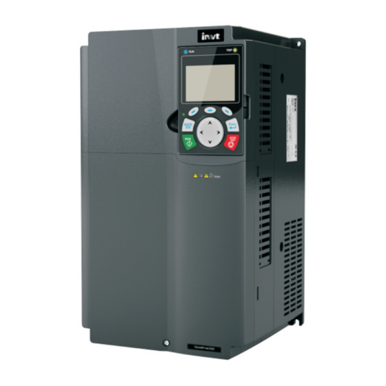
Goodrive350 series high-performance multifunction VFD Product overview 3.6.2 AC 3PH 520V (-15%)–690V (+10%) rated value Product model Output power (kW) Input current (A) Output current (A) GD350-022G-6 GD350-030G-6 GD350-037G-6 GD350-045G-6 GD350-055G-6 GD350-075G-6 GD350-090G-6 GD350-110G-6 GD350-132G-6 GD350-160G-6 GD350-185G-6 GD350-200G-6 GD350-220G-6 GD350-250G-6... - Page 23 Goodrive350 series high-performance multifunction VFD Product overview Figure 3.7 Structure diagram Item Description Upper cover Protects internal components and parts. Keypad For details, see section 5.4 Keypad operation. Lower cover Protects internal components and parts. Extension card Optional. For details, see Appendix A Extension cards.
-
Page 24: Installation Guide
INVT does not assume any liability whatsoever for any installation which breaches local laws and regulations. If recommendations given by INVT are not followed, the VFD may experience problems that the warranty does not cover. 4.2 Mechanical installation 4.2.1 Installation environment... -
Page 25: Installation Direction
Below 1000m. When the altitude exceeds 1000m, derate 1% for every additional 100m. Altitude When the installation site altitude exceeds 3000m, consult the local INVT dealer or office. Vibration The max. amplitude of vibration should not exceed 5.8m/s (0.6g) -
Page 26: Installation Mode
Goodrive350 series high-performance multifunction VFD Installation guide 4.2.3 Installation mode There are three kinds of installation modes based on different VFD dimensions. Wall-mounting: suitable for 380V 315kW and lower, and 660V 355kW and lower Flange-mounting: suitable for 380V 200kW and lower, and 660V 220kW and lower Floor-mounting: suitable for 380V 220–500kW, and 660V 250–630kW... -
Page 27: Multiple-Unit Installation
Goodrive350 series high-performance multifunction VFD Installation guide 4.2.5 Multiple-unit installation Hot air Cold air Figure 4.4 Parallel installation Note: When you install VFDs in different sizes, align the top of each VFD before installation for the convenience of future maintenance. -
Page 28: Vertical Installation
Goodrive350 series high-performance multifunction VFD Installation guide 4.2.6 Vertical installation Windshield Cold Cold Windshield Figure 4.5 Vertical installation Note: During vertical installation, you must install windshield, otherwise, the VFD will experience mutual interference, and the heat dissipation effect will be degraded. -
Page 29: Tilted Installation
Goodrive350 series high-performance multifunction VFD Installation guide 4.2.7 Tilted installation Cold Cold Cold Figure 4.6 Tilted installation Note: During tilted installation, it is a must to ensure the air inlet duct and air outlet duct are separated from each other to avoid mutual interference. -
Page 30: Standard Wiring Of Main Circuit
Goodrive350 series high-performance multifunction VFD Installation guide 4.3 Standard wiring of main circuit 4.3.1 Wiring diagram of main circuit Braking resistor (+) (-) Output reactor 3-phase Input power reactor 37kW and lower Output 380V(-15%) filter Input 440V(+10%) filter 50/60Hz Fuse... -
Page 31: Main Circuit Terminal Diagram
Goodrive350 series high-performance multifunction VFD Installation guide Braking unit DC reactor Braking resistor Output reactor Input reactor 22kW and higher Output 3-phase power filter 660V± 15% 50/60Hz Input filter Fuse Figure 4.8 Main circuit wiring diagram for AC 3PH 520V(-15%)–690V(+10%) Note: ... - Page 32 Goodrive350 series high-performance multifunction VFD Installation guide Figure 4.12 660V 22–45kW Figure 4.13 660V 55–132kW -23-...
- Page 33 Goodrive350 series high-performance multifunction VFD Installation guide Figure 4.14 380V 132–200kW and 660V 160–220kW Figure 4.15 380V 220–315kW and 660V 250–355kW -24-...
- Page 34 Goodrive350 series high-performance multifunction VFD Installation guide Figure 4.16 380V 355–500kW and 660V 400–630kW Terminal name 380V 132kW and 380V Terminal Function description 380V 37kW and higher 45–110kW lower 660V (inclusive) 3PH AC input terminals, R, S, T Main circuit power input...
-
Page 35: Wiring Procedure Of The Main Circuit Terminals
Goodrive350 series high-performance multifunction VFD Installation guide Terminal name 380V 132kW and 380V Terminal Function description 380V 37kW and higher 45–110kW lower 660V (inclusive) Braking resistor braking resistor terminal Not available terminal 2 Grounding terminal for safe protection; each machine must... -
Page 36: Standard Wiring Of Control Circuit
Goodrive350 series high-performance multifunction VFD Installation guide 4.4 Standard wiring of control circuit 4.4.1 Wiring diagram of basic control circuit Goodrive350 series VFD Forward running Analog output Jogging 0-10V/0-20mA Fault reset output HDIA HDIB Optional between high- speed pulse output and... - Page 37 Goodrive350 series high-performance multifunction VFD Installation guide Terminal Description Voltage or current output is set by toggle switch SW2 Error: ±0.5% at 25° C, when input is above 5V/10mA RO1A RO1 relay output; RO1A is NO, RO1B is NC, RO1C is common...
-
Page 38: Input/Output Signal Connection Diagram
Goodrive350 series high-performance multifunction VFD Installation guide 4.4.2 Input/output signal connection diagram Set NPN /PNP mode and internal/external power via U-type short-contact tag. NPN internal mode is adopted by default. R01AR02A S4 HDIA HDIB AI1 AI2 +10V H1 +24V +24V... -
Page 39: Wiring Protection
Goodrive350 series high-performance multifunction VFD Installation guide + 24V + 24V + 24V + 24V Internal power(PNP mode) External power(PNP mode) Figure 4.21 PNP mode 4.5 Wiring protection 4.5.1 Protect the VFD and input power cable in short-circuit Protect the VFD and input power cable during short-circuit to avoid thermal overload. -
Page 40: Bypass Connection
Goodrive350 series high-performance multifunction VFD Installation guide 4.5.4 Bypass connection In some critical occasions, industrial frequency conversion circuit is necessary to ensure proper operation of the system when a VFD fault occurs. In some special cases, such as, only soft startup is needed, it will convert to power-frequency operation directly after soft startup, corresponding bypass link is also needed. -
Page 41: Basic Operation Instructions
Goodrive350 series high-performance multifunction VFD Basic operation instructions 5 Basic operation instructions 5.1 What this chapter contains This chapter tells you how to use the VFD keypad and the commissioning procedures for common functions of the VFD. 5.2 Keypad introduction The VFD has been equipped with a LCD keypad as a standard configuration part. - Page 42 Goodrive350 series high-performance multifunction VFD Basic operation instructions Item Instruction LED on – the VFD is running Fault indicator; LED on – in fault state TRIP LED off – in normal state LED blinking – in pre-alarm state Short-cut key indicator, which displays...
- Page 43 Goodrive350 series high-performance multifunction VFD Basic operation instructions Item Instruction During running state, press the Stop/Reset key can stop running or autotuning; this key Stop/ (10) is limited by P07.04. During fault alarm state, Reset key all the control modes can be reset by this key.
-
Page 44: Keypad Display
Goodrive350 series high-performance multifunction VFD Basic operation instructions 16:02:35 Forward Local Ready 01: GD350 Set frequency 50.00 P17.00 DC bus voltage 540.0 P17.11 Digital input terminal state 0x0000 P17.12 Monitoring About Menu Figure 5.2 Main interface of LCD Area Name... -
Page 45: Stop Parameter Display State
Goodrive350 series high-performance multifunction VFD Basic operation instructions 5.3.1 Stop parameter display state When the VFD is in stop state, the keypad displays stop state parameters, and this interface is the main interface during power-on by default. Under stop state, parameters in various states can be displayed. -
Page 46: Fault Alarm Display State
Goodrive350 series high-performance multifunction VFD Basic operation instructions 16:02:35 Forward 16:02:35 Local Ready 01: GD350 Forward Local Ready 01: GD350 DC bus voltage DC bus voltage 540.00 540.00 P17.11 Digital input terminal state 0x0000 P17.12 2000.0 Digital output terminal state 0x0000 P17.13... - Page 47 Goodrive350 series high-performance multifunction VFD Basic operation instructions 16:02:35 Forward Local Ready 01: GD350 16:02:35 Forward Local Ready 16:02:35 Forward Local Ready 01: GD350 01: GD350 Set frequency Common parameter setup P00.10:Keypad setting frequency 50.00 P17.00 Parameter setup P00.00:Speed control mode...
- Page 48 Goodrive350 series high-performance multifunction VFD Basic operation instructions First-level Second-level Third-level Fourth-level setup xx Quick setup for function Pxx.xx code P00: Basic functions P00.xx P07: HMI P07.xx Basic P08: Enhance functions P08.xx parameter P11: Protection parameters P11.xx group setup P14: Serial communication P14.xx...
- Page 49 Goodrive350 series high-performance multifunction VFD Basic operation instructions First-level Second-level Third-level Fourth-level P28: Master/slave functions P28.xx P90: Customized function P90.xx group 1 P91: Customized function P91.xx Default group 2 function P92: Customized function group setup P92.xx group 3 P93: Customized function P93.xx...
-
Page 50: List Edit
Goodrive350 series high-performance multifunction VFD Basic operation instructions First-level Second-level Third-level Fourth-level Upload local function parameter to keypad Download complete keypad function parameter Operate the storage area 1: Download key function BACKUP01 parameters which are not in motor group Parameter... -
Page 51: Add Parameters To The Parameter List Displayed In Stop/Running State
Goodrive350 series high-performance multifunction VFD Basic operation instructions edit operation, it will return to the previous menu (parameter list remain unchanged). Note: For the parameter objects in the list header, shift-up operation will be invalid, and the same principle can be applied to the parameter objects in the list footer; after deleting a certain parameter, the parameter objects under it will be shifted up automatically. -
Page 52: Add Parameter To Common Parameter Setup List
Goodrive350 series high-performance multifunction VFD Basic operation instructions key, key or key to confirm the addition operation. If this parameter is not included in the "parameter displayed in stop state" list or "parameter displayed in running state" list, the parameter added will be at the end of the list; if the parameter is already in the "parameter displayed in stop state"... -
Page 53: Parameter Setup Edit Interface
Goodrive350 series high-performance multifunction VFD Basic operation instructions 16:02:35 Forward Current value:1 Default value:2 Local Ready 01:GD350 Current value:0 Authority:√ Default value:2 Authority:√ P00.00:Speed control mode 0:SVC 0 1:SVC 1 P00.01:Running command channel 1:SVC 1 2:V/F mode P00.02:Communication command channel 2:V/F mode... -
Page 54: Motor Parameter Autotuning
Goodrive350 series high-performance multifunction VFD Basic operation instructions key to enter state monitoring interface. After entering state monitoring interface, the current parameter value will be displayed in real time, this value is the actually detected value which cannot be modified. -
Page 55: System Setup
Goodrive350 series high-performance multifunction VFD Basic operation instructions areas for parameter backup, and each storage area can save the parameters of one VFD, namely it can save parameters of three VFDs in total. 16:02:35 Forward Local Ready Forward 16:02:35 Local... - Page 56 Goodrive350 series high-performance multifunction VFD Basic operation instructions Level 1 Level 2 Level 3 Level 4 2: AI2 Asynchr P02.00 Type of onous motor 1 3: AI3 Synchro nous P02.01 Rated power 4: High-speed of asynchronous pulse HDIA motor 1 P02.02: Rated...
- Page 57 Goodrive350 series high-performance multifunction VFD Basic operation instructions Level 1 Level 2 Level 3 Level 4 13: Set via P02.19 Rated EtherCAT/ current of PROFINET synchronous motor 1 communication 14: PLC card Whether to conduct autotuning? 15: Reserved Motor parameter 0: Keypad P00.01...
-
Page 58: Basic Operation Instruction
Goodrive350 series high-performance multifunction VFD Basic operation instructions Level 1 Level 2 Level 3 Level 4 time P00.12 Deceleration time 5.5 Basic operation instruction 5.5.1 What this section contains This section introduces the function modules inside the VFD. Ensure all the terminals are fixed and tightened firmly. - Page 59 Goodrive350 series high-performance multifunction VFD Basic operation instructions Start Power up after confirming the wiring is correct Restore to default value (P00.18=1) Set the motor parameters of Set the motor parameters of P02.01–P02.05 as per the P02.15–P02.19 as per the...
- Page 60 Goodrive350 series high-performance multifunction VFD Basic operation instructions Note: If fault occurred, rule out the fault cause according to "fault tracking". The running command channel can be set by terminal commands besides P00.01 and P00.02. Multi-function Multi-function terminal Multi-function terminal...
- Page 61 Goodrive350 series high-performance multifunction VFD Basic operation instructions Function Default Name Description code value when current motor is motor 1, only P02.06, P02.07 and P02.08 will be autotuned; when current motor is motor 2, only P12.06, P12.07 and P12.08 will be autotuned.
-
Page 62: Vector Control
Goodrive350 series high-performance multifunction VFD Basic operation instructions Function Default Name Description code value synchronous motor 1 on model Rated current of Depends P02.19 0.8–6000.0A synchronous motor 1 on model Function of multi-function 36: Command switches to keypad P05.01– digital input terminal 37: Command switches to terminal P05.06... - Page 63 Goodrive350 series high-performance multifunction VFD Basic operation instructions R S T Rectifier bridge φ Calculate i exciting current Park IGBT conversion pulse bridge Calculate i torque current φ Position observation Voltage detection Speed identific ation Flux linkage observation Park Clark...
- Page 64 Goodrive350 series high-performance multifunction VFD Basic operation instructions Function Default Name Description code value only P12.06, P12.07 and P12.08 will be autotuned. 4: Rotary autotuning 2, which is similar to rotary autotuning 1 but is only applicable to asynchronous motors.
- Page 65 Goodrive350 series high-performance multifunction VFD Basic operation instructions Function Default Name Description code value communication 9: Ethernet communication 10: Pulse frequency HDIB 11: EtherCAT/PROFINET communication 12: PLC Note: For setting sources 2–6 and 10, 100% corresponds to three times the rated motor current.
- Page 66 Goodrive350 series high-performance multifunction VFD Basic operation instructions Function Default Name Description code value rotation in torque control 0: Keypad (P03.20) 1: AI1 2: AI2 3: AI3 4: Pulse frequency HDIA 5: Modbus communication 6: PROFIBUS/CANopen/DeviceNet Source of upper limit setup communication P03.18...
-
Page 67: Svpwm Control Mode
Goodrive350 series high-performance multifunction VFD Basic operation instructions Function Default Name Description code value 0: Reserved 1: Reserved Hundreds place: Whether to enable ASR integral separation 0: Disable 1: Enable Thousands place: Reserved 0: Reserved 1: Reserved P03.36 ASR differential gain 0.00–10.00s... - Page 68 Goodrive350 series high-performance multifunction VFD Basic operation instructions Output voltage Torque -down V/F curve (power of 1.3) Torque -down V/F curve (power of 1.7) Straight-type Torque -down V/F curve (power of 2.0) Square-type Output frequency The VFD also provides multi-point V/F curve. You can alter the V/F curve outputted by VFD through setting the voltage and frequency of the three points in the middle.
- Page 69 Goodrive350 series high-performance multifunction VFD Basic operation instructions Output voltage V boost cut-off Output frequency f Energy-saving run During actual running, the VFD can search for the max. efficiency point to keep running in the most efficient state to save energy.
- Page 70 Goodrive350 series high-performance multifunction VFD Basic operation instructions Customized V/F curve (V/F separation) function: When selecting customized V/F curve function, you can set the reference channels and acceleration/deceleration time of voltage and frequency respectively, which will form a real-time V/F...
- Page 71 Goodrive350 series high-performance multifunction VFD Basic operation instructions curve through combination. Note: This kind of V/F curve separation can be applied in various frequency-conversion power sources, however, you should be cautious of parameter setup as improper setup may damage the machine.
- Page 72 Goodrive350 series high-performance multifunction VFD Basic operation instructions Function Default Name Description code value motor 1 V/F frequency point 2 P04.05 P04.03– P04.07 0.00Hz of motor 1 V/F voltage point 2 of P04.06 0.0%–110.0% 0.0% motor 1 V/F frequency point 3 P04.07...
- Page 73 Goodrive350 series high-performance multifunction VFD Basic operation instructions Function Default Name Description code value of motor 2 V/F voltage point 3 of P04.21 0.0%–110.0% 0.0% motor 2 V/F slip compensation P04.22 0.0–200.0% 100.0% gain of motor 2 Low-frequency P04.23 oscillation control 0–100...
- Page 74 Goodrive350 series high-performance multifunction VFD Basic operation instructions Function Default Name Description code value constant power zone When the synchronous motor VF control mode is enabled, this parameter is used to set the reactive Input current 1 in current of the motor when the output frequency is P04.34...
- Page 75 Goodrive350 series high-performance multifunction VFD Basic operation instructions Function Default Name Description code value need to modify this parameter. Setting range: 0–16000 Enable/disable IF 0: Disabled P04.40 mode for 1: Enabled asynchronous motor 1 When IF control is adopted for asynchronous motor Current setting in IF 1, this parameter is used to set the output current.
-
Page 76: Torque Control
Goodrive350 series high-performance multifunction VFD Basic operation instructions Function Default Name Description code value Starting frequency point for switching off P04.49 0.00–P04.51 10.00Hz IF mode for asynchronous motor 2 End frequency point for switching off IF P04.50 P04.44–P00.03 25.00Hz mode for... - Page 77 Goodrive350 series high-performance multifunction VFD Basic operation instructions -68-...
- Page 78 Goodrive350 series high-performance multifunction VFD Basic operation instructions Function Default Name Description code value 0:SVC 0 1:SVC 1 Speed control 2:SVPWM P00.00 mode 3:VC Note: If 0, 1 or 3 is selected, it is required to carry out motor parameter autotuning first.
- Page 79 Goodrive350 series high-performance multifunction VFD Basic operation instructions Function Default Name Description code value 9: Pulse frequency HDIB (the same as above) 10: EtherCAT/PROFINET communication 11: PLC 12: Reserved Note: For setting sources 1–11, 100% is relative to the max. frequency.
-
Page 80: Motor Parameter
Goodrive350 series high-performance multifunction VFD Basic operation instructions Function Default Name Description code value communication 7: Ethernet communication 8: Pulse frequency HDIB 9: EtherCAT/PROFINET communication 10: PLC 11: Reserved Note: For setting sources 1–4 and 8, 100% corresponds to three times the rated motor current. - Page 81 Goodrive350 series high-performance multifunction VFD Basic operation instructions autotuning. Although the motor does not run during static autotuning, the motor is stilled supplied with power, do not touch the motor during autotuning; otherwise, electric shock may occur. If the motor has been connected to load, do not carry out rotary autotuning;...
- Page 82 Goodrive350 series high-performance multifunction VFD Basic operation instructions Ready P00.01=0 (controlled by keypad) Synchronous Asynchronous Motor type motor motor (P02.00) P02.00=1 P02.00=0 Input motor nameplate Input motor nameplate (P02.15–P02.19) (P02.01–P02.05) Set autotuning mode (P00.15) Complete parameter Complete parameter Partial parameter rotary...
- Page 83 Goodrive350 series high-performance multifunction VFD Basic operation instructions synchronous motor 1) can be obtained via calculation. 4. Motor autotuning can be carried out on current motor only, if you need to perform autotuning on the other motor, switch over the motor through selecting the switch-over channel of motor 1 and motor 2 by setting the ones of P08.31.
- Page 84 Goodrive350 series high-performance multifunction VFD Basic operation instructions Function Default Name Description code value Rated voltage of Depends P02.04 0–1200V asynchronous motor 1 on model Rated current of Depends P02.05 0.8–6000.0A asynchronous motor 1 on model Stator resistance of Depends P02.06...
- Page 85 Goodrive350 series high-performance multifunction VFD Basic operation instructions Function Default Name Description code value 1: Switch over by Modbus communication 2: Switch over by PROFIBUS / CANopen /DeviceNet 3: Switch over by Ethernet communication 4: Switch over by EtherCAT/PROFINET communication...
-
Page 86: Start/Stop Control
Goodrive350 series high-performance multifunction VFD Basic operation instructions Function Default Name Description code value synchronous motor 2 Rated voltage of Depends P12.18 0–1200V synchronous motor 2 on model Rated current of Depends P12.19 0.8–6000.0A synchronous motor 2 on model Stator resistance of Depends P12.20... - Page 87 Goodrive350 series high-performance multifunction VFD Basic operation instructions Logic diagram for running command after power-on -78-...
- Page 88 Goodrive350 series high-performance multifunction VFD Basic operation instructions Logic diagram for restart after power-off Standby Keypad The running state Stop Stop before power cut Restart after Communi power-cut cation Delay time of restart Waiting time of restart at >P01.23 power-cut>P01.22 P01.21...
- Page 89 Goodrive350 series high-performance multifunction VFD Basic operation instructions Function Default Name Description code value frequency P01.03 DC brake current before start 0.0–100.0% 0.0% P01.04 DC brake time before start 0.00–50.00s 0.00s 0: Straight line 1: S curve Acceleration/deceleration P01.05 Note: If mode 1 is selected, it is required mode to set P01.07, P01.27 and P01.08...
- Page 90 Goodrive350 series high-performance multifunction VFD Basic operation instructions Function Default Name Description code value Waiting time of restart after P01.22 0.0–3600.0s (valid when P01.21 is 1) 1.0s power cut P01.23 Start delay 0.0–60.0s 0.0s P01.24 Stop speed delay 0.0–100.0s 0.0s...
-
Page 91: Frequency Setup
Goodrive350 series high-performance multifunction VFD Basic operation instructions Function Default Name Description code value Depends P08.08 Deceleration time at jogging 0.0–3600.0s on model Depends P08.00 Acceleration time 2 0.0–3600.0s on model Depends P08.01 Declaration time 2 0.0–3600.0s on model Depends P08.02... - Page 92 Goodrive350 series high-performance multifunction VFD Basic operation instructions channel. The VFD supports switch-over between different reference channels, and the rules for channel switch-over are shown below. Multi-function terminal Multi-function terminal Multi-function terminal Present reference function 13 function 14 function 15...
- Page 93 Goodrive350 series high-performance multifunction VFD Basic operation instructions Multi-function terminal Multi-function terminal Multi-function terminal Present reference function 13 function 14 function 15 channel Channel A switches to Combination setup Combination setup P00.09 channel B switches to channel A switches to channel B...
- Page 94 Goodrive350 series high-performance multifunction VFD Basic operation instructions Function Default Name Description code value 9: PROFIBUS/CANopen/DeviceNet communication 10: Ethernet communication 11: High speed pulse HDIB 12: Pulse string AB 13: EtherCAT/PROFINET communication 14: PLC card 15: Reserved Reference object of B 0: Max.
-
Page 95: Analog Input
Goodrive350 series high-performance multifunction VFD Basic operation instructions Function Default Name Description code value Hundreds: Action selection at stop 0: Valid 1: Valid during running, clear after stop 2: Valid during running, clear after receiving stop command UP terminal frequency P08.45... - Page 96 Goodrive350 series high-performance multifunction VFD Basic operation instructions Related parameter list: Function Default Name Description code value 0x00–0x11 Ones: HDIA input type 0: HDIA is high-speed pulse input P05.00 HDI input type 1: HDIA is digital input 0x00 Tens: HDIB input type...
-
Page 97: Analog Output
Goodrive350 series high-performance multifunction VFD Basic operation instructions Function Default Name Description code value Upper limit frequency of P05.39 –50.000kHz P05.41 50.000kHz HDIA Corresponding setting of P05.42 upper limit frequency of -300.0%–300.0% 100.0% HDIA HDIA frequency input filter P05.43 0.000s–10.000s 0.030s... - Page 98 Goodrive350 series high-performance multifunction VFD Basic operation instructions Analog output curve setting Analog output selection Analog output filter P06.17 P06.18 P06.14 P06.21 P06.19 P06.20 (Default value is 0) P06.00 (HDO output type) P06.27 P06.28 P06.16 P06.31 P06.29 P06.30 (Default value is 0) 0: Open collector high-speed P06.00...
- Page 99 Goodrive350 series high-performance multifunction VFD Basic operation instructions Set value Function Description Set value 1 of Modbus -1000–1000 communication Set value 2 of Modbus -1000–1000 communication Set value 1 of PROFIBUS/CANopen/Device -1000–1000 Net communication Set value 2 of PROFIBUS/CANopen/Device -1000–1000...
- Page 100 Goodrive350 series high-performance multifunction VFD Basic operation instructions Set value Function Description 32–47 Reserved Related parameter list: Function Default Name Description code value 0: Open collector high-speed pulse P06.00 HDO output type output 1: Open collector output 0: Running frequency (0–Max. output P06.14...
- Page 101 Goodrive350 series high-performance multifunction VFD Basic operation instructions Function Default Name Description code value 17: Value 2 set through PROFIBUS/CANopen/DeviceNet (0– 1000) 18: Value 1 set through Ethernet 1 (0– 1000) 19: Value 2 set through Ethernet 2 (0– 1000) 20: HDIB input (0.00–50.00kHz)
-
Page 102: Digital Input
Goodrive350 series high-performance multifunction VFD Basic operation instructions Function Default Name Description code value P06.26 P06.27 Lower limit of HDO output -300.0%–P06.29 0.0% Corresponding HDO output of P06.28 0.00–50.00kHz 0.0kHz lower limit P06.29 Upper limit of HDO output P06.27–300.0% 100.0% Corresponding HDO output of P06.30... - Page 103 Goodrive350 series high-performance multifunction VFD Basic operation instructions Function Description value Forward jogging Frequency when jogging, see P08.06, P08.07 and P08.08 for jogging acceleration/deceleration time. Reverse jogging The VFD blocks output, and the stop process of motor is uncontrolled by the VFD. This mode is applied in cases of Coast to stop large-inertia load and free stop time;...
- Page 104 Goodrive350 series high-performance multifunction VFD Basic operation instructions Function Description value setting B frequency reference channel can be switched by no. 15 function. 16-step speeds can be set by combining digital states of Multi-step speed terminal 1 these four terminals.
- Page 105 Goodrive350 series high-performance multifunction VFD Basic operation instructions Function Description value control and torque control control mode, or vice versa. Ensure the VFD will not be impacted by external signals Acceleration/deceleration (except for stop command), and maintains current output disabled frequency.
- Page 106 Goodrive350 series high-performance multifunction VFD Basic operation instructions Function Description value When this terminal is valid in stop state, switch to FVC switches to V/F control SVPWM control. When this terminal is valid in stop state, switch to Switch to FVC control closed-loop vector control.
- Page 107 Goodrive350 series high-performance multifunction VFD Basic operation instructions Function Default Name Description code value 7: Fault reset 8: Running pause 9: External fault input 10: Frequency increase (UP) 11: Frequency decrease (DOWN) 12: Clear frequency increase/decrease setting 13: Switch-over between setup A and...
- Page 108 Goodrive350 series high-performance multifunction VFD Basic operation instructions Function Default Name Description code value motor 2 36: Command switches to keypad 37: Command switches to terminal 38: Command switches to communication 39: Pre-exciting command 40: Zero out power consumption quantity...
-
Page 109: Digital Output
Goodrive350 series high-performance multifunction VFD Basic operation instructions Function Default Name Description code value 3: 3-wire control 2 P05.12 S1 terminal switch-on delay 0.000–50.000s 0.000s P05.13 S1 terminal switch-off delay 0.000–50.000s 0.000s P05.14 S2 terminal switch-on delay 0.000–50.000s 0.000s P05.15 S2 terminal switch-off delay 0.000–50.000s... - Page 110 Goodrive350 series high-performance multifunction VFD Basic operation instructions Function Description value Invalid Output terminal has no function Output ON signal when there is frequency output during In running running Output ON signal when there is frequency output during In forward running...
- Page 111 Goodrive350 series high-performance multifunction VFD Basic operation instructions Function Description value Virtual terminal output of Output corresponding signal based on the set value of POROFIBUS/CANopen PROFIBUS/CANopen; output ON signal when it is set to communication 1, output OFF signal when it is set to 0...
- Page 112 Goodrive350 series high-performance multifunction VFD Basic operation instructions Function Default Name Description code value 0: Open collector high-speed pulse output P06.00 HDO output type 1: Open collector output 0: Invalid P06.01 Y1 output selection 1: In running P06.02 HDO output selection...
- Page 113 Goodrive350 series high-performance multifunction VFD Basic operation instructions Function Default Name Description code value 34: Virtual terminal output of EtherCAT/PROFINET communication 35: Reserved 36: Speed/position control switch-over completed 37: Any frequency reached 38–40: Reserved 41: C_Y1 from PLC (You need to set P27.00 to 1.)
-
Page 114: Simple Plc
Goodrive350 series high-performance multifunction VFD Basic operation instructions Function Default Name Description code value Digital output terminal P17.13 state 5.5.13 Simple PLC Simple PLC is a multi-step speed generator, and the VFD can change the running frequency and direction automatically based on the running time to fulfill process requirements. Previously, such function was realized with external PLC, while now, the VFD itself can achieve this function. - Page 115 Goodrive350 series high-performance multifunction VFD Basic operation instructions Function Default Name Description code value P10.02 Multi-step speed 0 0.0% -100.0–100.0% P10.03 Running time of 0 step 0.0s 0.0–6553.5s (min) P10.04 Multi-step speed 1 0.0% -100.0–100.0% P10.05 Running time of 1 step 0.0s...
-
Page 116: Multi-Step Speed Running
Goodrive350 series high-performance multifunction VFD Basic operation instructions Function Default Name Description code value 0: Restart from the first section P10.36 PLC restart mode 1: Continue running at the frequency when interruption occurred Acceleration/deceleration P10.34 time of 0–7 stage of simple 0x0000–0XFFFF... - Page 117 Goodrive350 series high-performance multifunction VFD Basic operation instructions P10.02 multi-step speed 0 BIT0 P10.34 P10.03 running time of 0 step BIT1 Terminal function 16 Acceleration/deceleration time Multi-step speed selection of 0–7 section of terminal 1 simple PLC Terminal function 17 P10.04 multi-step speed 1...
-
Page 118: Pid Control
Goodrive350 series high-performance multifunction VFD Basic operation instructions Function Default Name Description code value P10.12 Multi-step speed 5 -100.0–100.0% 0.0% P10.13 Running time of 5 step 0.0–6553.5s (min) 0.0s P10.14 Multi-step speed 6 -100.0–100.0% 0.0% P10.15 Running time of 6 step 0.0–6553.5s (min) - Page 119 Goodrive350 series high-performance multifunction VFD Basic operation instructions difference between feedback signal of controlled variables and signal of the target, thus forming a negative feedback system to keep the controlled variables above the target. It is suitable for flow control, pressure control, temperature control, etc. Diagram of basic principles for output frequency regulation is shown in the figure below.
- Page 120 Goodrive350 series high-performance multifunction VFD Basic operation instructions magnitude of the deviation itself. Differential control is used to control the feedback signal variation based on the variation trend. Differential regulator should be used with caution as it may easily enlarge the system interferences, especially those with high variation frequency.
- Page 121 Goodrive350 series high-performance multifunction VFD Basic operation instructions time (Ti) and prolong derivative time (Td) to stabilize control as fast as possible. After adjustment Response Before adjustment Time t Control long-term vibration: If the cycle of periodic vibration is longer than the set value of integral time (Ti), it indicates the integral action is too strong, prolong the integral time (Ti) to control vibration.
- Page 122 Goodrive350 series high-performance multifunction VFD Basic operation instructions Function Default Name Description code value 8: Ethernet communication 9: High-speed pulse HDIB 10: EtherCAT/PROFINET communication 11: Programmable extension card 12: Reserved Pre-set PID reference of P09.01 -100.0%–100.0% 0.0% keypad 0: AI1...
- Page 123 Goodrive350 series high-performance multifunction VFD Basic operation instructions Function Default Name Description code value 0: Continue integral control after the frequency reaches upper/lower limit 1: Stop integral control after the frequency reaches upper/lower limit Tens: 0: The same with the main reference...
-
Page 124: Run At Wobbling Frequency
Goodrive350 series high-performance multifunction VFD Basic operation instructions 5.5.16 Run at wobbling frequency Wobbling frequency is mainly applied in cases where transverse movement and winding functions are needed like textile and chemical fiber industries. The typical working process is shown as below. -
Page 125: Local Encoder Input
Goodrive350 series high-performance multifunction VFD Basic operation instructions Function Default Name Description code value 26: Wobbling frequency pause (stop at P05.01– Digital input function current frequency) P05.06 selection 27: Wobbling frequency reset (revert to center frequency) Amplitude of wobbling P08.15 0.0–100.0% (relative to set frequency) -
Page 126: Commissioning Procedures For Closed-Loop Control, Position Control And Spindle Positioning
Goodrive350 series high-performance multifunction VFD Basic operation instructions 5.5.18 Commissioning procedures for closed-loop control, position control and spindle positioning 1. Commissioning procedures for closed-loop vector control of asynchronous motor Step 1: Restore to default value via keypad Step 2: Set P00.03, P00.04 and P02 group motor nameplate parameters... - Page 127 Goodrive350 series high-performance multifunction VFD Basic operation instructions pole pair number × 1024), eg, if pole pair number is 4, set P20.01 to 4096. Step 4: Ensure the encoder is installed and set correctly When motor stops, observe whether P18.21 (resolver angle) fluctuates, if it fluctuates sharply, check the wiring and grounding.
- Page 128 Goodrive350 series high-performance multifunction VFD Basic operation instructions Step 5: Set P21.00=0001 to set positioning mode to position control, namely pulse-string control. There are four kinds of pulse command modes, which can be set by P21.01 (pulse command mode). In position control mode, you can check the high bit and low bit of position reference and feedback, P18.02 (count value of Z pulse), P18.00 (actual frequency of encoder), P18.17 (pulse command...
- Page 129 Goodrive350 series high-performance multifunction VFD Basic operation instructions closed-loop vector control, which aim to fulfill the control requirements of closed-loop vector control, thus realizing spindle positioning function in either position control or speed control mode. Step 5: Set P22.00.bit0=1 to enable spindle positioning, set P22.00.bit1 to select spindle zero input. If the system adopts encoder for speed measurement, set P22.00.bit1 to 0 to select Z pulse input;...
- Page 130 Goodrive350 series high-performance multifunction VFD Basic operation instructions Step 11: Spindle reference point selection (bit0 of P22.00) Encoder Z pulse positioning supports the following spindle positioning modes: a) the encoder is installed on the motor shaft, the motor shaft and spindle is 1:1 rigid connection;...
-
Page 131: Fault Handling
Goodrive350 series high-performance multifunction VFD Basic operation instructions Set P21.16.bit1=1 to enable cyclic positioning. The cyclic positioning is divided into continuous mode and repetitive mode; you can also carry out cyclic positioning through terminal function (no. 55, enable digital positioning cycle) 6. - Page 132 Goodrive350 series high-performance multifunction VFD Basic operation instructions In running Fault occurred, and the keypad displayed fault code Figure out the fault cause based on the fault code Figure out the most possible cause according to P07.33– P07.40 Rule out...
- Page 133 Goodrive350 series high-performance multifunction VFD Basic operation instructions Function Default Name Description code value 13: Phase loss on input side (SPI) 14: Phase loss on output side (SPO) 15: Rectifier module overheat (OH1) 16: Inverter module overheat (OH2) 17: External fault (EF)
- Page 134 Goodrive350 series high-performance multifunction VFD Basic operation instructions Function Default Name Description code value 56: Encoder UVW loss fault (ENCUV) 57: PROFINET communication timeout fault (E-PN) 58: CAN communication fault (SECAN) 59: Motor over-temperature fault (OT) 60: Card slot 1 card identification failure...
- Page 135 Goodrive350 series high-performance multifunction VFD Basic operation instructions Function Default Name Description code value Running frequency of the P07.41 0.00Hz–P00.03 0.00Hz last fault Ramp reference frequency P07.42 0.00Hz–P00.03 0.00Hz of the last fault Output voltage of the last P07.43 0–1200V...
-
Page 136: Function Parameter List
Goodrive350 series high-performance multifunction VFD Function parameter list 6 Function parameter list 6.1 What this chapter contains This chapter lists all the function codes and corresponding description of each function code. 6.2 Function parameter list The function parameters of the VFD are divided into groups by function. Among the function parameter groups, the P98 group is the analog input and output calibration group, while the P99 group contains the factory function parameters, which are user inaccessible. -
Page 137: P00--Basic Functions
Goodrive350 series high-performance multifunction VFD Function parameter list enter the interface only with the correct user password. For the factory parameters, you need to enter the correct factory password to enter the interface. (You are not advised to modify the factory parameters. - Page 138 Goodrive350 series high-performance multifunction VFD Function parameter list Function Default Name Description Modify code value frequency) The lower limit of running frequency is the lower limit value of VFD output frequency. When the set frequency is lower than the lower...
- Page 139 (P00.03). Deceleration time is the time needed from decelerating from Max. output frequency (P00.03) to 0Hz. Deceleration Depends Goodrive350 series VFD defines four groups of ○ P00.12 time 1 on model acceleration and deceleration time, which can be selected via multi-function digital input terminals (P05 group).
- Page 140 Goodrive350 series high-performance multifunction VFD Function parameter list Function Default Name Description Modify code value follows: growing switch consumption, enlarged temperature rise, impacted output capacity; under high carrier frequency, the VFD needs to be derated for use, meanwhile, the leakage current will increase, which increases electromagnetic interference to the surroundings.
-
Page 141: P01--Start/Stop Control
Goodrive350 series high-performance multifunction VFD Function parameter list Function Default Name Description Modify code value P00.17 Reserved Reserved 0: No operation 1: Restore to default value 2: Clear fault history Function Note: After the selected function operations are ◎ P00.18... - Page 142 Goodrive350 series high-performance multifunction VFD Function parameter list Function Default Name Description Modify code value and then it will accelerate after the set DC brake time before startup elapses. If the set DC brake time is 0, DC brake will be invalid.
- Page 143 Goodrive350 series high-performance multifunction VFD Function parameter list Function Default Name Description Modify code value Output frequency f Time of ending t1=P01.06 section of t2=P01.07 ◎ P01.07 0.1s t3=P01.27 acceleration S Time t t4=P01.28 curve Setting range: 0.0–50.0s 0: Decelerate to stop; after stop command is valid,...
- Page 144 Goodrive350 series high-performance multifunction VFD Function parameter list Function Default Name Description Modify code value forward/reverse the threshold set by P01.14 during setting rotation forward/reverse rotation of the VFD, as shown below. Output frequency f Forward Switch over after starting frequency...
- Page 145 Goodrive350 series high-performance multifunction VFD Function parameter list Function Default Name Description Modify code value below lower limit 0: Run in lower limit of the frequency (lower limit 1: Stop should be larger 2: Sleep than 0) When the set frequency is below lower limit frequency, the VFD coasts to stop;...
- Page 146 Goodrive350 series high-performance multifunction VFD Function parameter list Function Default Name Description Modify code value Output frequency t1=P01.22 t2=P01.23 Running Running Power off Power on Setting range: 0.0–3600.0s (valid when P01.21=1) This function code sets the delay of the VFD’s...
-
Page 147: P02--Parameters Of Motor 1
Goodrive350 series high-performance multifunction VFD Function parameter list Function Default Name Description Modify code value Setting range of P01.31: 0.0–50.0s Pre-exciting time ○ P01.32 0–10.000s 0.000s of jogging Starting frequency of ○ P01.33 0–P00.03 0.00Hz braking for jogging to stop Delay to enter ○... - Page 148 Goodrive350 series high-performance multifunction VFD Function parameter list Function Default Name Description Modify code value motor 1 Mutual inductance of Depends ○ P02.09 0.1–6553.5Mh asynchronous on model motor 1 No-load current Depends ○ P02.10 of asynchronous 0.1–6553.5A on model motor 1...
- Page 149 Goodrive350 series high-performance multifunction VFD Function parameter list Function Default Name Description Modify code value Number of pole pairs of ◎ P02.17 1–128 synchronous motor 1 Rated voltage of Depends ◎ P02.18 synchronous 0–1200V on model motor 1 Rated current of Depends ◎...
-
Page 150: P03--Vector Control Of Motor 1
Goodrive350 series high-performance multifunction VFD Function parameter list Function Default Name Description Modify code value frequency-variable motor is not affected by the rotating speed, there is no need to adjust the protection value during low speed running. Motor overload multiples M=Iout/(In×K) In is rated motor current, lout is VFD output current, K is motor overload protection coefficient. - Page 151 Goodrive350 series high-performance multifunction VFD Function parameter list Function Default Name Description Modify code value Speed loop parameter is P03.00 and P03.01; above P03.06, ○ P03.01 0.200s integral time 1 speed loop PI parameter is P03.03 and P03.04; in between, PI parameter is obtained by linear Switch low point ○...
- Page 152 Goodrive350 series high-performance multifunction VFD Function parameter list Function Default Name Description Modify code value coefficient control speed offset. (motoring) Setting range: 50–200% Vector control slip ○ P03.08 compensation 100% coefficient (generating) Current loop Note: ○ P03.09 proportional 1. These two parameters are used to adjust PI...
- Page 153 Goodrive350 series high-performance multifunction VFD Function parameter list Function Default Name Description Modify code value 0: Keypad (P03.16) 1: AI1 (100% corresponds to max. frequency) 2: AI2 (the same as above) 3: AI3 (the same as above) 4: Pulse frequency HDIA (the same as above)
- Page 154 Goodrive350 series high-performance multifunction VFD Function parameter list Function Default Name Description Modify code value torque during 2: AI2 motoring 3: AI3 4: Pulse frequency HDIA 5: Modbus communication 6: PROFIBUS/CANopen/DeviceNet communication 7: Ethernet communication 8: Pulse frequency HDIB 9: EtherCAT/PROFINET communication...
- Page 155 Goodrive350 series high-performance multifunction VFD Function parameter list Function Default Name Description Modify code value constant-power zone Flux-weakening coefficient of motor Min. Min. flux-weakening limit of motor P03.22 and P03.23 are valid during constant flux-weakening ○ power. When motor speed is above rated speed, P03.23...
- Page 156 Goodrive350 series high-performance multifunction VFD Function parameter list Function Default Name Description Modify code value coefficient Corresponding frequency of high ○ P03.31 P03.29–400.00Hz 50.00Hz speed friction torque Torque control 0:Disable ◎ P03.32 enable 1:Enable Flux weakening ○ P03.33 0–8000 1200 integral gain ●...
-
Page 157: P04--V/F Control
Goodrive350 series high-performance multifunction VFD Function parameter list Function Default Name Description Modify code value compensation 1: Enable enable Upper limit of Limit the max. inertia compensation torque to inertia prevent inertia compensation torque from being ○ P03.41 10.0% compensation too large. - Page 158 Goodrive350 series high-performance multifunction VFD Function parameter list Function Default Name Description Modify code value 3: Torque down V/F curve (1.7 order) 4: Torque down V/F curve (2.0 order) Curve 2–4 are suitable for torque-variable load of fan pump and similar equipment. You can make adjustment based on load characteristics to achieve optimal energy-saving effect.
- Page 159 Goodrive350 series high-performance multifunction VFD Function parameter list Function Default Name Description Modify code value Output voltage boost Output frequency Cut-off Setting range of P04.01: 0.0%: (automatic) 0.1%– 10.0% Setting range of P04.02: 0.0%–50.0% V/F frequency When P04.00 =1 (multi-point V/F curve), you can ○...
- Page 160 30.00Hz Setting range of P04.12: 0.00Hz–P00.03 (Max. of motor 1 output frequency) This parameter defines the V/F curve of motor 2 of the Goodrive350 series to meet various load characteristic requirements. 0: Straight V/F curve; V/F curve setup ◎ P04.13...
- Page 161 Goodrive350 series high-performance multifunction VFD Function parameter list Function Default Name Description Modify code value V/F frequency voltage of motor 2) ○ P04.18 0.00Hz point 2 of motor 2 Setting range of P04.18: P04.16–P04.20 Setting range of P04.19: 0.0%–110.0% (rated V/F voltage point ○...
- Page 162 Goodrive350 series high-performance multifunction VFD Function parameter list Function Default Name Description Modify code value 2: AI2 3: AI3 4: HDIA 5: Multi-step (the set value is determined by P10 group) 6: PID 7: Modbus communication 8: PROFIBUS/CANopen/DeviceNet communication 9: Ethernet communication...
- Page 163 Goodrive350 series high-performance multifunction VFD Function parameter list Function Default Name Description Modify code value When the synchronous motor VF control mode is enabled, this parameter is used to set the reactive Input current 1 in current of the motor when the output frequency is ○...
- Page 164 Goodrive350 series high-performance multifunction VFD Function parameter list Function Default Name Description Modify code value asynchronous motor 1 When IF control is adopted for asynchronous Current setting in motor 1, this parameter is used to set the output IF mode for ○...
-
Page 165: P05--Input Terminals
Goodrive350 series high-performance multifunction VFD Function parameter list Function Default Name Description Modify code value mode for coefficient of the output current closed-loop asynchronous control. motor 2 Setting range: 0–5000 Starting frequency point for switching off ○ P04.49 0.00–P04.51 10.00Hz... - Page 166 Goodrive350 series high-performance multifunction VFD Function parameter list Function Default Name Description Modify code value terminal 7: Fault reset 8: Running pause Function of HDIA ◎ P05.05 9: External fault input terminal 10: Frequency increase (UP) 11: Frequency decrease (DOWN)
- Page 167 Goodrive350 series high-performance multifunction VFD Function parameter list Function Default Name Description Modify code value 42: Source of upper torque limit switches to keypad 43: Position reference point input (only S6, S7 and S8 are valid) 44: Spindle orientation disabled...
- Page 168 Goodrive350 series high-performance multifunction VFD Function parameter list Function Default Name Description Modify code value When the bit is set to 0, input terminal polarity is positive; When the bit is set to 1, input terminal polarity is negative; 0x000–0x3F Set S1–S4, filter time of HDI terminal sampling.
- Page 169 Goodrive350 series high-performance multifunction VFD Function parameter list Function Default Name Description Modify code value Running FWD REV command Stop Forward running Stop Reverse running 2: 3-wire control 1; This mode defines Sin as enabling terminal, and the running command is generated by FWD, the direction is controlled by REV.
- Page 170 Goodrive350 series high-performance multifunction VFD Function parameter list Function Default Name Description Modify code value 3: 3-wire control 2; This mode defines Sin as enabling terminal. The running command is generated by FWD or REV, and they control the running direction. During running, the terminal Sin...
- Page 171 Goodrive350 series high-performance multifunction VFD Function parameter list Function Default Name Description Modify code value switch-on delay of the programmable input terminals during level variation from switch-on to switch-off . S1 terminal ○ P05.13 0.000s switch-off delay Si electrical level...
- Page 172 Goodrive350 series high-performance multifunction VFD Function parameter list Function Default Name Description Modify code value setting of lower Corresponding setting 100% limit of AI2 Intermediate ○ P05.31 0.00V value 1 of AI2 -10V Corresponding 20mA setting of ○ P05.32 0.0%...
- Page 173 Goodrive350 series high-performance multifunction VFD Function parameter list Function Default Name Description Modify code value Corresponding setting of lower ○ P05.40 -300.0%–300.0% 0.0% limit frequency of HDIA Upper limit 50.000 P05.39 –50.000kHz ○ P05.41 frequency of HDIA Corresponding setting of upper ○...
-
Page 174: P06--Output Terminals
Goodrive350 series high-performance multifunction VFD Function parameter list P06––Output terminals Function Default Name Description Modify code value 0: Open collector high-speed pulse output: Max. frequency of the pulse is 50.00kHz. For details ◎ P06.00 HDO output type about the related functions, see P06.27–P06.31. - Page 175 Goodrive350 series high-performance multifunction VFD Function parameter list Function Default Name Description Modify code value 30: Positioning completed 31: Spindle zeroing completed 32: Spindle scale-division completed 33: In speed limit 34–35: Reserved 36: Speed/position control switch-over completed 37: Any frequency reached 38–40: Reserved...
- Page 176 Goodrive350 series high-performance multifunction VFD Function parameter list Function Default Name Description Modify code value Relay RO1 Y electric level ○ P06.10 0.000s switch-on delay invalid Invalid Valid Y valid Switch on Switch off Relay RO1 ○ delay P06.11 delay 0.000s...
- Page 177 Goodrive350 series high-performance multifunction VFD Function parameter list Function Default Name Description Modify code value rated current) 23: Exciting current (bipolar, 0–Triple the motor rated current) 24: Set frequency (bipolar, 0–Max. output frequency) 25: Ramp reference frequency (bipolar, 0–Max. output frequency) 26: Rotational speed (bipolar, 0–Speed...
-
Page 178: P07--Hmi
Goodrive350 series high-performance multifunction VFD Function parameter list Function Default Name Description Modify code value P06.26 Lower limit of ○ P06.27 -300.0%–P06.29 0.00% HDO output Corresponding ○ P06.28 HDO output of 0.00–50.00kHz 0.00kHz lower limit Upper limit of ○ P06.29 P06.27–300.0%... - Page 179 Goodrive350 series high-performance multifunction VFD Function parameter list Function Default Name Description Modify code value user password. Exercise caution when using this function. P07.01 Reserved Range: 0x00–0x27 Ones: Function selection of QUICK/JOG key 0: No function 1: Jogging 2: Reserved 3: Forward/reverse rotation switch-over ◎...
- Page 180 Goodrive350 series high-performance multifunction VFD Function parameter list Function Default Name Description Modify code value display Linear speed=mechanical speed×P07.10 coefficient Temperature of ● P07.11 rectifier bridge -20.0–120.0° C module Temperature of ● P07.12 -20.0–120.0° C inverter module Software version ●...
- Page 181 Goodrive350 series high-performance multifunction VFD Function parameter list Function Default Name Description Modify code value Type of the 8: Overvoltage during deceleration (OV2) ● P07.31 4th-last fault 9: Overvoltage during constant speed (OV3) 10: Bus undervoltage fault (UV) 11: Motor overload (OL1)
- Page 182 Goodrive350 series high-performance multifunction VFD Function parameter list Function Default Name Description Modify code value 47: PLC card customized fault 3 (P-E3) 48: PLC card customized fault 4 (P-E4) 49: PLC card customized fault 5 (P-E5) 50: PLC card customized fault 6 (P-E6)
- Page 183 Goodrive350 series high-performance multifunction VFD Function parameter list Function Default Name Description Modify code value Max. temperature ● P07.38 -20.0–120.0° C 0.0° C of present fault Input terminal ● P07.39 state of present 0x0000–0xFFFF fault Output terminal ● P07.40 state of present 0x0000–0xFFFF...
-
Page 184: P08--Enhanced Functions
Deceleration Depends ○ P08.01 See P00.11 and P00.12 for detailed definitions. time 2 on model Goodrive350 series VFD defines four groups of Acceleration Depends ○ P08.02 acceleration/deceleration time, which can be time 3 on model selected by multi-function digital input terminal... - Page 185 Goodrive350 series high-performance multifunction VFD Function parameter list Function Default Name Description Modify code value Jump frequency frequency, the VFD will run at the boundary of ○ P08.10 0.00Hz amplitude 1 jump frequency. The VFD can avoid mechanical resonance point ○...
- Page 186 Goodrive350 series high-performance multifunction VFD Function parameter list Function Default Name Description Modify code value acceleration/deceleration only Output torque 0: Calculated based on torque current ○ P08.22 calculation mode Number of 0: Two decimal points ○ P08.23 decimal points of...
- Page 187 Goodrive350 series high-performance multifunction VFD Function parameter list Function Default Name Description Modify code value 4: Switch over by EtherCAT/PROFINET communication Tens: Motor switch over during running 0: Disable switch over during running 1: Enable switch over during running FDT1 level When the output frequency exceeds the ○...
- Page 188 Goodrive350 series high-performance multifunction VFD Function parameter list Function Default Name Description Modify code value Output frequency Detection amplitude frequency Time t RO1, RO2 Time t Setting range: 0.00Hz–P00.03 (Max. output frequency) Enable/disable energy- 0: Disable energy-consumption ○ P08.37 consumption...
- Page 189 Goodrive350 series high-performance multifunction VFD Function parameter list Function Default Name Description Modify code value 1: Compensation method 2 Thousands place: PWM loading mode selection 0: Interruptive loading 1: Normal loading 0x00–0x1111 Ones place: 0: Disable overmodulation 1: Enable overmodulation...
- Page 190 Goodrive350 series high-performance multifunction VFD Function parameter list Function Default Name Description Modify code value frequency decremental change rate 0x000–0x111 Ones place: Action selection at power-off during frequency adjusting through digitals. 0: Save the setting at power-off. 1: Clear the setting at power-off.
-
Page 191: P09--Pid Control
Goodrive350 series high-performance multifunction VFD Function parameter list Function Default Name Description Modify code value 2) Better cooling effect. During flux braking, the stator current of the motor increases, while the rotor current does not change, while the cooling effect of stator is much more effective than that of the rotor. - Page 192 Goodrive350 series high-performance multifunction VFD Function parameter list Function Default Name Description Modify code value 4: High-speed pulse HDIA 5: Multi-step 6: Modbus communication 7: PROFIBUS/CANopen/DeviceNet communication 8: Ethernet communication 9: High-speed pulse HDIB 10: EtherCAT/PROFINET communication 11: Programmable extension card...
- Page 193 Goodrive350 series high-performance multifunction VFD Function parameter list Function Default Name Description Modify code value decrease for PID to reach balance, eg, tension PID control of winding 1: PID output is negative characteristics: namely the feedback signal is less than PID reference,...
- Page 194 Goodrive350 series high-performance multifunction VFD Function parameter list Function Default Name Description Modify code value Setting range: 0.00–10.00s It means the sampling cycle of feedback. The regulator operates once during each sampling Sampling cycle ○ P09.07 cycle. The larger the sampling cycle, the slower 0.001s...
- Page 195 Goodrive350 series high-performance multifunction VFD Function parameter list Function Default Name Description Modify code value Output frequency t1<T2, so the VFD continues running t2=P09.12 PIDE P09.11 Running Fault output PIDE Setting range of P09.11: 0.0–100.0% Setting range of P09.12: 0.0–3600.0s 0x0000–0x1111...
-
Page 196: P10--Simple Plc And Multi-Step Speed Control
Goodrive350 series high-performance multifunction VFD Function parameter list Function Default Name Description Modify code value 0.0% ○ P09.17 Reserved -100.0–100.0% Low-frequency ○ P09.18 0.00–10.00s 0.90s integral time (Ti) Low-frequency ○ P09.19 differential time 0.00–10.00s 0.00s (Td) Low-frequency point of PID ○... - Page 197 P00.01. ○ P10.17 0.0s(min) step Goodrive350 series VFD can set 16-step speed, P10.18 Multi-step speed 8 ○ which are set by combined codes of multi-step 0.0% terminals 1–4 (set by S terminal, correspond to Running time of ○...
- Page 198 Goodrive350 series high-performance multifunction VFD Function parameter list Function Default Name Description Modify code value Multi-step speed higher than that of the keypad, analog, high-speed ○ P10.28 0.0% pulse, PID, and communication settings. The relation between terminal 1, terminal 2, Running time of ○...
-
Page 199: P11--Protection Parameters
Goodrive350 series high-performance multifunction VFD Function parameter list Function Default Name Description Modify code value hexadecimal number, finally, set corresponding function code. Acceleration/deceleration time 1 is set by P00.11 and P00.12; Acceleration/deceleration time 2 is set by P08.00 and P08.01; Acceleration/deceleration time 3 is set by P08.02 and P08.03;... - Page 200 Goodrive350 series high-performance multifunction VFD Function parameter list Function Default Name Description Modify code value power down Energy braking 0: Enable ◎ P11.02 for stop 1: Disable 0: Disable 1: Enable DC bus voltage V Overvoltage stall threshold Overvoltage stall ○...
- Page 201 Goodrive350 series high-performance multifunction VFD Function parameter list Function Default Name Description Modify code value When the output current is detected to be lower than the current-limit level again, it will continue accelerated running. Output current A Current-limit threshold Time t...
- Page 202 Goodrive350 series high-performance multifunction VFD Function parameter list Function Default Name Description Modify code value If the VFD or motor output current is larger than G type: Overload the overload pre-alarm detection level (P11.09), 150% ○ P11.09 pre-alarm and the duration exceeds the overload pre-alarm...
- Page 203 Goodrive350 series high-performance multifunction VFD Function parameter list Function Default Name Description Modify code value detection time detection time. Note: Speed deviation protection is invalid when P11.15 is set to 0.0. Speed Actual detection value Set detection value Time t...
- Page 204 Goodrive350 series high-performance multifunction VFD Function parameter list Function Default Name Description Modify code value during Setting range: 0–1000 overvoltage stall Integral This parameter is used to set the integral coefficient of coefficient of the bus voltage regulator during ○...
-
Page 205: P12--Parameters Of Motor 2
Goodrive350 series high-performance multifunction VFD Function parameter list P12––Parameters of motor 2 Function Default Name Description Modify code value 0: Asynchronous motor ◎ P12.00 Type of motor 2 1: Synchronous motor Rated power of Depends ◎ P12.01 asynchronous 0.1–3000.0kW on model... - Page 206 Goodrive350 series high-performance multifunction VFD Function parameter list Function Default Name Description Modify code value iron core of asynchronous motor 2 Magnetic saturation coefficient 2 of ○ P12.12 0.0–100.0% iron core of asynchronous motor 2 Magnetic saturation coefficient 3 of ○...
- Page 207 Goodrive350 series high-performance multifunction VFD Function parameter list Function Default Name Description Modify code value motor 2 Direct-axis inductance of Depends ○ P12.21 0.01–655.35mH synchronous on model motor 2 Quadrature-axis inductance of Depends ○ P12.22 0.01–655.35mH synchronous on model motor 2...
-
Page 208: P13--Control Parameters Of Synchronous Motor
Goodrive350 series high-performance multifunction VFD Function parameter list Function Default Name Description Modify code value calibration coefficient of motor 2 0: Display based on the motor type; under this mode, only parameters related to current motor Parameter ○ P12.29 type will be displayed. - Page 209 Goodrive350 series high-performance multifunction VFD Function parameter list Function Default Name Description Modify code value Switch-over ○ P13.04 frequency of 0.00Hz–P00.03 (Max. output frequency) 10.00Hz input current High-frequency superposition ◎ P13.05 200Hz–1000Hz 500Hz frequency (reserved) This parameter is used to set the pulse current threshold when the initial magnetic pole position is detected in the pulse mode.
-
Page 210: P14--Serial Communication Function
Goodrive350 series high-performance multifunction VFD Function parameter list Function Default Name Description Modify code value injection current ○ P13.19 Reserved 0–65535 P14––Serial communication function Function Default Name Description Modify code value Setting range: 1–247 When the master is writing frames, and the slave... - Page 211 Goodrive350 series high-performance multifunction VFD Function parameter list Function Default Name Description Modify code value 3: No parity check (N, 8, 2) for RTU 4: Even parity (E, 8, 2) for RTU 5: Odd parity (O, 8, 2) for RTU 0–200ms...
-
Page 212: P15--Functions Of Communication Extension Card 1
Goodrive350 series high-performance multifunction VFD Function parameter list P15––Functions of communication extension card 1 Function Default Name Description Modify code value P15.00– See the operation manual of communication extension card for details P15.27 ◎ P15.28 Master/slave 0–127 communication address ◎... -
Page 213: P17--State-Check Functions
Goodrive350 series high-performance multifunction VFD Function parameter list Function Default Name Description Modify code value extension card in card slot 1 Communication timeout period of 0.0–600.0s P16.28 0.0s extension card in If it is set to 0.0, offline fault will not be detected... - Page 214 Goodrive350 series high-performance multifunction VFD Function parameter list Function Default Name Description Modify code value Display current output torque of the VFD; 100% relative to rated motor torque, during forward running, positive value is motoring state, negative Motor output ●...
- Page 215 Goodrive350 series high-performance multifunction VFD Function parameter list Function Default Name Description Modify code value HDIB input Display input frequency of HDIB 0.000 ● P17.22 frequency Range: 0.000–50.000kHz PID reference Display PID reference value ● P17.23 0.0% value Range: -100.0–100.0%...
- Page 216 Goodrive350 series high-performance multifunction VFD Function parameter list Function Default Name Description Modify code value current side Range: 0.0–5000.0A Display output torque value, during forward running, positive value is motoring state, negative value is generating state; during reverse running, ●...
-
Page 217: P18--Closed-Loop Control State Check
Goodrive350 series high-performance multifunction VFD Function parameter list Function Default Name Description Modify code value of torque control Inertia ● P17.45 compensation -100.0%–100.0% 0.0% torque Friction ● P17.46 compensation -100.0%–100.0% 0.0% torque ● P17.47 Motor pole pairs 0–65535 VFD overload ●... - Page 218 Goodrive350 series high-performance multifunction VFD Function parameter list Function Default Name Description Modify code value reference value Range: 0–65535 High bit of High bit of position feedback value, zero out after ● P18.05 position feedback stop. value Range: 0–30000 Low bit of Low bit of position feedback value, zero out after ●...
- Page 219 Goodrive350 series high-performance multifunction VFD Function parameter list Function Default Name Description Modify code value board measured speed value Pulse command (A2, B2 terminal) is converted to Pulse command the set frequency, and it is valid under pulse ● P18.17 0.00Hz...
-
Page 220: P19--Extension Card State Check
Goodrive350 series high-performance multifunction VFD Function parameter list Function Default Name Description Modify code value Angle compensation ● P18.29 value of -180.0–180.0 0.00 synchronous motor ● P18.30 Reserved 0–65535 Pulse reference ● P18.31 0–65535 Z pulse value Pulse-given main control board ●... -
Page 221: P20--Encoder Of Motor 1
Goodrive350 series high-performance multifunction VFD Function parameter list Function Default Name Description Modify code value 16: Modbus communication card 17: EtherCAT communication card 18: BacNet communication card 19: DeviceNet communication card Software version ● P19.03 of the extension 0.00–655.35 0.00... - Page 222 Goodrive350 series high-performance multifunction VFD Function parameter list Function Default Name Description Modify code value Ones: AB direction 0: Forward 1: Reverse Tens: Z pulse direction (reserved) ◎ P20.02 Encoder direction 0: Forward 0x000 1: Reverse Hundreds: CD/UVW pole signal direction...
- Page 223 Goodrive350 series high-performance multifunction VFD Function parameter list Function Default Name Description Modify code value 0x00–0x11 Ones: Z pulse 0: Do not detect Enable Z pulse ○ P20.08 1: Enable 0x10 offline detection Tens: UVW pulse (for synchronous motor) 0: Do not detect...
- Page 224 Goodrive350 series high-performance multifunction VFD Function parameter list Function Default Name Description Modify code value 1: Filter Bit1: Encoder signal filter mode (set Bit0 or Bit2 to 0: Self-adaptive filter 1: Use P20.18 filter parameters Bit2: Enable/disable encoder frequency-division output filter...
-
Page 225: P21--Position Control
Goodrive350 series high-performance multifunction VFD Function parameter list Function Default Name Description Modify code value Synchronous motor angle -200.0–200.0% ○ P20.23 100.0% compensation coefficient ○ P20.24 Reserved 0–65535 P21––Position control Function Default Name Description Modify code value Ones: Control mode selection... - Page 226 Goodrive350 series high-performance multifunction VFD Function parameter list Function Default Name Description Modify code value up; if channel B is of high electric level, the edge counts down. 2: A: Positive pulse Channel A is positive pulse; channel B needs no wiring 3: A/B dual-channel pulse;...
- Page 227 Goodrive350 series high-performance multifunction VFD Function parameter list Function Default Name Description Modify code value 2: Torque command 3: Speed command 3–5: Reserved Torque command level during ○ P21.05 0.0–100.0% (rated motor torque) 10.0% position gain switch-over Speed command level during ○...
- Page 228 Goodrive350 series high-performance multifunction VFD Function parameter list Function Default Name Description Modify code value time constant Position The position feedforward filter time constant during ◎ P21.15 command filter pulse string positioning. 0.0ms time constant 0.0–3200.0ms Bit0: Positioning mode selection...
- Page 229 Goodrive350 series high-performance multifunction VFD Function parameter list Function Default Name Description Modify code value Bit10: Whether to save the encoder pulse counting value 0: Do not save 1: Save Bit 11: Reserved Bit12: Positioning curve selection (reserved) 0: Straight line 1: S curve Set digital positioning position;...
-
Page 230: P22--Spindle Positioning
Goodrive350 series high-performance multifunction VFD Function parameter list Function Default Name Description Modify code value Setting range: 0.000–60.000s Pulse ○ P21.26 superposition 0–65535 value Pulse ○ P21.27 superposition 0–6553.5 speed Acceleration/dec eleration time ○ P21.28 000.0–3000.0s 5.0s after disabling pulse... - Page 231 Goodrive350 series high-performance multifunction VFD Function parameter list Function Default Name Description Modify code value 1: Near-by direction positioning Bit5: Positioning mode selection 2 0: Forward positioning 1: Reverse positioning Bit6: Zeroing command selection 0: Electric level mode 1: Pulse mode...
- Page 232 Goodrive350 series high-performance multifunction VFD Function parameter list Function Default Name Description Modify code value Spindle zeroing ○ P22.06 Setting range: 0–39999 position 3 Spindle You can select seven spindle scale-division values ○ P22.07 scale-division by terminals (function code 48, 49 and 50).
-
Page 233: P23--Vector Control Of Motor 2
Goodrive350 series high-performance multifunction VFD Function parameter list Function Default Name Description Modify code value 1: AI1 2: AI2 3: AI3 Analog filter time ○ P22.19 0.0ms–1000.0ms 1.0ms of rigid tapping Max. frequency ○ P22.20 0.00–400.00Hz 50.00Hz of rigid tapping... - Page 234 Goodrive350 series high-performance multifunction VFD Function parameter list Function Default Name Description Modify code value of vector control can be adjusted by setting the proportional coefficient and integral time of speed regulator. Increase proportional gain or decrease integral time can accelerate dynamic response of...
-
Page 235: P24--Encoder Of Motor 2
Goodrive350 series high-performance multifunction VFD Function parameter list Function Default Name Description Modify code value 2. Fit for SVC mode 0 (P00.00=0) and VC mode (P00.00=3); 3. The value of this function code will be updated automatically after parameter autotuning of synchronous motor is done. - Page 236 Goodrive350 series high-performance multifunction VFD Function parameter list Function Default Name Description Modify code value Hundreds: CD/UVW pole signal direction 0: Forward 1: Reverse Detection time of ○ P24.03 encoder offline 0.0–10.0s 2.0s fault Detection time of ○ P24.04 encoder reversal 0.0–100.0s...
- Page 237 Goodrive350 series high-performance multifunction VFD Function parameter list Function Default Name Description Modify code value Relative electric angle of encoder Z pulse and Initial angle of Z ○ P24.09 motor pole position. 0.00 pulse Setting range: 0.00–359.99 Relative electric angle of encoder position and Initial angle of the ○...
- Page 238 Goodrive350 series high-performance multifunction VFD Function parameter list Function Default Name Description Modify code value 1: Filter Bit3: Reserved Bit4: Enable/disable pulse reference filter 0: No filter 1: Filter Bit5: Pulse reference filter mode 0: Self-adaptive filter 1: Use P24.19 filter parameters...
-
Page 239: P25--Extension I/O Card Input Functions
Goodrive350 series high-performance multifunction VFD Function parameter list P25––Extension I/O card input functions Function Default Name Description Modify code value HDI3 input type 0: HDI3 is high-speed pulse input ◎ P25.00 selection 1: HDI3 is digital input S5 terminal ◎... - Page 240 Goodrive350 series high-performance multifunction VFD Function parameter list Function Default Name Description Modify code value S6 switch-off ○ P25.15 0.000s delay S7 terminal ○ P25.16 0.000s switch-on delay S7 switch-off ○ P25.17 0.000s delay S8 terminal ○ P25.18 0.000s switch-on delay S8 switch-off ○...
- Page 241 Goodrive350 series high-performance multifunction VFD Function parameter list Function Default Name Description Modify code value setting of upper input, increase this value properly can enhance limit of AI4 the anti-interference capacity of analog variables; however, it will also degrade the sensitivity of analog input.
-
Page 242: P26--Output Functions Of Extension I/O Card
Goodrive350 series high-performance multifunction VFD Function parameter list Function Default Name Description Modify code value Range: 0–1 AI4 input signal ○ P25.41 0: Voltage type type 1: Current type P25.42– ○ Reserved 0–65535 P25.45 P26––Output functions of extension I/O card... - Page 243 Goodrive350 series high-performance multifunction VFD Function parameter list Function Default Name Description Modify code value delay Y electric level Y2 switch-on invalid ○ P26.15 0.000s Invalid Valid Y valid delay Switch on Switch off delay delay Y2 switch-off ○ P26.16 0.000s...
- Page 244 Goodrive350 series high-performance multifunction VFD Function parameter list Function Default Name Description Modify code value switch-on delay Relay RO10 ○ P26.34 0.000s switch-off delay AO2 output ○ P26.35 selection AO3 output The same with P06.14 ○ P26.36 selection ○ P26.37...
-
Page 245: P28--Master/Slave Control Functions
Goodrive350 series high-performance multifunction VFD Function parameter list P28––Master/slave control functions Function Default Name Description Modify code value ◎ 0: The master/slave control is invalid Master/slave P28.00 1: This machine is a master mode selection 2: This machine is a slave ◎... -
Page 246: P90--Customized Function Group 1
Goodrive350 series high-performance multifunction VFD Function parameter list P90––Customized function group 1 Function Default Name Description Modify code value P90.00– ○ Reserved 0–65535 P90.39 P91––Customized function group 2 Function Default Name Description Modify code value P91.00– ○ Reserved 0–65535 P91.39 P92 ––Customized function group 3... -
Page 247: Troubleshooting
When fault occurred, process the fault as shown below. 1. When VFD fault occurred, confirm whether keypad display is improper? If yes, contact INVT; 2. If keypad works properly, check the function codes in P07 group to confirm the corresponding fault record parameters, and determine the real state when current fault occurred through parameters;... - Page 248 Goodrive350 series high-performance multifunction VFD Troubleshooting Fault Fault type Possible cause Corrective measures code Over-voltage during Deceleration time is too Check input power; acceleration short; Check whether load Exception occurred to input deceleration time is too short; Over-voltage during voltage;...
- Page 249 Goodrive350 series high-performance multifunction VFD Troubleshooting Fault Fault type Possible cause Corrective measures code Phase loss occurred to U, V, Phase loss on W output (or the three Check the output wiring; output side phases of motor is Check the motor and cable...
- Page 250 Goodrive350 series high-performance multifunction VFD Troubleshooting Fault Fault type Possible cause Corrective measures code EEPROM is damaged PID feedback offline; Check PID feedback signal PID feedback offline PIDE PID feedback source wires; fault disappears; Check PID feedback source Braking circuit fault or Check the braking unit, replace braking tube is damaged;...
- Page 251 Goodrive350 series high-performance multifunction VFD Troubleshooting Fault Fault type Possible cause Corrective measures code circuit fault 1 connected to the ground; proper; Current detection circuit is Replace the hall component; faulty; Replace the main control Actual motor power setup board;...
- Page 252 Goodrive350 series high-performance multifunction VFD Troubleshooting Fault Fault type Possible cause Corrective measures code temperature detection Check whether temperature Exception occurred to sensor is proper; resistor; Check the motor and perform Long-time overload running maintenance on the motor or exception occurred...
- Page 253 Goodrive350 series high-performance multifunction VFD Troubleshooting Fault Fault type Possible cause Corrective measures code port is damaged, if yes, replace the insertion port after power down Confirm whether the extension card inserted can be supported; Stabilize the extension card There is data transmission in...
- Page 254 Goodrive350 series high-performance multifunction VFD Troubleshooting Fault Fault type Possible cause Corrective measures code Check whether the insertion port is damaged, if yes, replace the insertion port after power down Confirm whether the extension card inserted can be supported; Stabilize the extension card...
-
Page 255: Other State
Goodrive350 series high-performance multifunction VFD Troubleshooting Fault Fault type Possible cause Corrective measures code There is no data Check whether the DeviceNet card transmission between the communication card wiring is E-DEV communication communication card and the loose or dropped timeout fault... -
Page 256: Analysis On Common Faults
Goodrive350 series high-performance multifunction VFD Troubleshooting 7.6 Analysis on common faults 7.6.1 Motor fails to work Motor fails to work Whether the POWER Whether the air switch indicator is on? Close the air and EM contactor on the Whether the keypad... -
Page 257: Motor Vibrates
Goodrive350 series high-performance multifunction VFD Troubleshooting 7.6.2 Motor vibrates Motor vibrates or emits an unusual sound Whether the motor Set the motor type parameters and motor type and parameters are set correctly ? correctly Whether autotuning is Perform autotuning performed? -
Page 258: Overvoltage
Goodrive350 series high-performance multifunction VFD Troubleshooting 7.6.3 Overvoltage Overvoltage fault Whether the voltage of the power Ensure the power supply supply is within the standard range? meets the requirement Whether UVW on the output side of the VFD is short to... -
Page 259: Unusual Heating Of Motor
Goodrive350 series high-performance multifunction VFD Troubleshooting 7.6.5 Unusual heating of motor Unusual heating of the motor Whether the motor Set the motor parameters parameters are set correctly correctly? Whether parameter Parameter autotuning is autotune performed? Whether the VFD runs at a... -
Page 260: Vfd Overheating
Goodrive350 series high-performance multifunction VFD Troubleshooting 7.6.6 VFD overheating VFD overheating Whether the load is too Reduce the load and heavy or the capacity of increase the capacity the VFD is too small? of the VFD Whether the ambient Add a cooling device... -
Page 261: Motor Stalls During Acc
Goodrive350 series high-performance multifunction VFD Troubleshooting 7.6.7 Motor stalls during ACC Motor stalls during Whether the ACC Increase the ACC time is too short? time Check the voltage of the Use larger cables, shorten the terminals of the motor with a wiring distance, adjust the voltage multimeter. -
Page 262: Overcurrent
Goodrive350 series high-performance multifunction VFD Troubleshooting 7.6.8 Overcurrent Overcurrent Whether UVW on the Rectify the short-to- output side of the VFD is ground fault, and short to ground? Remove configure the motor the motor cable and cables properly checked whether it is connected to earth. -
Page 263: Countermeasures On Common Interference
Goodrive350 series high-performance multifunction VFD Troubleshooting 7.7 Countermeasures on common interference 7.7.1 Interference on meter switches and sensors Interference phenomenon Pressure, temperature, displacement, and other signals of a sensor are collected and displayed by a human-machine interaction device. The values are incorrectly displayed as follows after the VFD is started: 1. -
Page 264: Interference On Communication
Goodrive350 series high-performance multifunction VFD Troubleshooting the capacitor needs to be added on the terminal of the temperature meter.; if an electronic ruler is to transmit signals of 0 to 30 V to a PLC signal terminal, the capacitor needs to be added on the terminal of the PLC. -
Page 265: Failure To Stop And Indicator Shimmering Due To Motor Cable Coupling
Goodrive350 series high-performance multifunction VFD Troubleshooting 4. Try to short GND of the VFD to its ground terminal (PE). 5. Try to add a safety capacitor of 0.1 μF on the power terminal of the upper computer (PLC, HMI, and touch screen). During this process, pay attention to the voltage of the power supply and the voltage endurance capability of the capacitor. -
Page 266: Live Device Chassis
Goodrive350 series high-performance multifunction VFD Troubleshooting have strong anti-interference capability, and thus can prevent the impact of high-frequency leakage current. Electronic RCD Electromagnetic RCD Requiring highly sensitive, accurate, and stable zero-phase sequence current Low cost, high sensitivity, small in volume,... -
Page 267: Maintenance And Hardware Fault Diagnosis
This chapter describes how to carry out preventive maintenance on the VFD. 8.2 Periodical inspection Little maintenance is required when the VFD is installed in the environment that meets requirements. The following table describes the routine maintenance periods recommended by INVT. Subject Item... - Page 268 Goodrive350 series high-performance multifunction VFD Maintenance and hardware fault diagnosis Subject Item Method Criterion Check whether the conductors are deformed or No exception Visual inspection their color change due to occurs. Conductor and overheat. wire Check whether the wire No exception...
-
Page 269: Cooling Fan
For more details about maintenance, contact the local INVT office, or visit our website http://www.invt.com, and choose Support > Services. 8.3 Cooling fan The service life of the cooling fan of the VFD is more than 25,000 hours. The actual service life of the cooling fan is related to the use of the VFD and the temperature in the ambient environment. -
Page 270: Capacitor
Goodrive350 series high-performance multifunction VFD Maintenance and hardware fault diagnosis Cooling fan replacement: Read the safety precautions carefully and follow the instructions to perform operations. Otherwise, physical injuries or damage to the device may be caused. 1. Stop the device, disconnect the AC power supply, and wait for a time no shorter than the waiting time designated on the VFD. -
Page 271: Electrolytic Capacitor Replacement
Otherwise, physical injuries or damage to the device may be caused. The electrolytic capacitor of a VFD must be replaced if it has been used for more than 35,000 hours. For details about the replacement, contact the local INVT office. -262-... -
Page 272: Power Cable
Goodrive350 series high-performance multifunction VFD Maintenance and hardware fault diagnosis 8.5 Power cable Read the safety precautions carefully and follow the instructions to perform operations. Otherwise, physical injuries or damage to the device may be caused. 1. Stop the VFD, disconnect the power supply, and wait for a time no shorter than the waiting time designated on the VFD. -
Page 273: Communication
Goodrive350 series high-performance multifunction VFD Communication 9 Communication 9.1 What this chapter contains This chapter describes the communication of the VFD. The VFD provides RS485 communication interfaces and adopts the master-slave communication based on the international standard Modbus communication protocol. You can implement centralized... - Page 274 Goodrive350 series high-performance multifunction VFD Communication Max. transmission Max. transmission Baud rate (bps) Baud rate (bps) distance distance 2400 1800 m 9600 800 m 4800 1200 m 19200 600 m When RS485 interfaces are used for long-distance communication, it is recommended that you use shielded cables, and use the shield layer as the ground wires.
- Page 275 Goodrive350 series high-performance multifunction VFD Communication 120Ω 120Ω 32 # Figure 9.2 On-site chrysanthemum connection diagram Master Figure 9.3 Simplified chrysanthemum connection diagram Shielded twisted pair 120Ω 485 + 485+ 485 + Terminal resistor 485- 485 - 485- Earth Earth...
-
Page 276: Rtu Mode
Goodrive350 series high-performance multifunction VFD Communication Use shielded cable, if possible, in multi-device connection. The baud rates, data bit check settings, and other basic parameters of all the devices on the RS485 line must be set consistently, and addresses cannot be repeated. - Page 277 Goodrive350 series high-performance multifunction VFD Communication RTU data frame format Modbus packet Start with an idle time (at End with an idle time (at Slave Function least the transmission Data Check least the transmission address code time of 3.5 bytes) time of 3.5 bytes)
- Page 278 Goodrive350 series high-performance multifunction VFD Communication Definition of even check: Before the data is transmitted, an even check bit is added to indicate whether the number of "1" in the to-be-transmitted data is odd or even. If it is even, the check bit is set to "0";...
-
Page 279: Rtu Command Code And Communication Data
Goodrive350 series high-performance multifunction VFD Communication while(data_length--) crc_value^=×data_value++; for(i=0;i<8;i++) if(crc_value&0x0001) crc_value=(crc_value>>1)^0xa001; else crc_value=crc_value>>1; return(crc_value); In the ladder logic, CKSM uses the table look-up method to calculate the CRC value according to the content in the frame. The program of this method is simple, and the calculation is fast, but the ROM space occupied is large. - Page 280 Goodrive350 series high-performance multifunction VFD Communication the start address MSB of data quantity LSB of data quantity LSB of CRC MSB of CRC T1-T2-T3-T4 (transmission time of 3.5 bytes) The value in START and END is "T1-T2-T3-T4 (transmission time of 3.5 bytes)", indicating that the RS485 needs to stay idle for at least the transmission time of 3.5 bytes.
-
Page 281: Command Code 06H, Writing A Word
Goodrive350 series high-performance multifunction VFD Communication "Number of bytes" indicates the number of bytes between a byte (not included) and the CRC byte (not included). The value 04 indicates that there are four bytes of data between "Number of bytes" and "LSB of CRC", that is, "MSB of data in 0004H", "LSB of data in 0004H", "MSB of data in 0005H", and... -
Page 282: Command Code 10H, Continuous Writing
Goodrive350 series high-performance multifunction VFD Communication Sub-function code Description 0000 Return data based on query requests For example, to query about the circuit detection information about the VFD whose address is 01H, the query and return strings are the same, and the format is described in the following tables. -
Page 283: Data Address Definition
Goodrive350 series high-performance multifunction VFD Communication LSB of data quantity Number of bytes MSB of data to be written to 0004H LSB of data to be written to 0004H MSB of data to be written to 0005H LSB of data to be written to 0005H... - Page 284 Goodrive350 series high-performance multifunction VFD Communication Function Setting Default Name Description Modify code range value selection Note: The parameters in the P99 group are set by the manufacturer. They cannot be read or modified. Some parameters cannot be modified when the VFD is running; some cannot be modified regardless of the state of the VFD.
- Page 285 Goodrive350 series high-performance multifunction VFD Communication Function Address Data description Setting of the upper limit of the reverse running 2006H frequency (0–Fmax, unit: 0.01 Hz) Upper limit of the electromotion torque (0–3000, 2007H 1000 corresponding to 100.0% of the rated current of the VFD) Upper limit of the braking torque (0–3000, 1000...
- Page 286 Goodrive350 series high-performance multifunction VFD Communication Function Address Data description Bit0: =0: Not ready to run =1: Ready to run Bi1–2: =00: Motor 1 =01: Motor 2 =10: Motor 3 =11: Motor 4 Bit3: =0: Asynchronous machine =1: Synchronous machine Bit4: =0: No overload alarm =1: Overload alarm Bit5–Bit6: =00: Keypad-based control...
-
Page 287: Fieldbus Scale
Goodrive350 series high-performance multifunction VFD Communication Function Address Data description high-speed pulse 1 Read input of 3011H high-speed pulse 2 Read current step of 3012H 0–15 multi-step speed External length 3013H 0–65535 External count value 3014H 0–65535 Torque setting 3015H -300.0–+300.0% (unit: 0.1%) -
Page 288: Error Message Response
Goodrive350 series high-performance multifunction VFD Communication Function Default Name Description code value P01.20 Wake-up-from-sleep delay 0.0–3600.0s (valid when P01.19 is 2) 0.0s 0: Restart is disabled P01.21 Restart after power cut 1: Restart is enabled The value specified in "Description" or "Default value" contains one decimal, so the fieldbus scale is 10. - Page 289 Goodrive350 series high-performance multifunction VFD Communication Code Name Definition For the VFD, the data address in the request of the upper Invalid data computer is not allowed. In particular, the combination of the address register address and the number of the to-be-transmitted bytes is invalid.
-
Page 290: Read/Write Operation Example
Goodrive350 series high-performance multifunction VFD Communication the cause of the exception. After receiving the exception response, the typical processing of the master device is to transmit the request message again or modify the command based on the fault information. For example, to set the "Running command channel" (P00.01, the parameter address is 0001H) of... - Page 291 Goodrive350 series high-performance multifunction VFD Communication 07 1B 00 06 B5 59 Read Start 6 parameters in total address command address Assume that the following response is returned: 03 03 0C 00 23 00 23 00 23 00 23 00 23...
- Page 292 Goodrive350 series high-performance multifunction VFD Communication Function Default Name Description Modify code value Setting range: Max (P00.04, 10.00) –630.00Hz From the number of decimals, we can see that the fieldbus scale of the "Max. output frequency" (P00.03) is 100. Multiply 100 Hz by 100. The value 10000 is obtained, and it is 2710H in the hexadecimal form.
- Page 293 (P00.03). Deceleration time is the time needed from decelerating from Max. output frequency (P00.03) to 0Hz. Deceleration Depends Goodrive350 series VFD defines four groups of ○ P00.12 time 1 on model acceleration and deceleration time, which can be selected via multi-function digital input terminals (P05 group).
- Page 294 Goodrive350 series high-performance multifunction VFD Communication 9.4.8.4 Modbus communication commissioning example A PC is used as the host, an RS232-RS485 converter is used for signal conversion, and the PC serial port used by the converter is COM1 (an RS232 port). The upper computer commissioning software is the serial port commissioning assistant Commix, which can be downloaded from the Internet.
-
Page 295: Common Communication Faults
Goodrive350 series high-performance multifunction VFD Communication 20 00 00 01 42 28 Parameter Write Forward running address address command 9.5 Common communication faults Common communication faults include the following: No response is returned. The VFD returns an exception response. -
Page 296: Appendix A Extension Cards
Goodrive350 series high-performance multifunction VFD Extension cards Appendix A Extension cards A.1 Model definition EC-PG 5 01-05 ① ② ③ ④ ⑤ Field identifier Field description Naming example ① Product category EC: Extension card PG: PG card PC: PLC programmable card ②... - Page 297 Goodrive350 series high-performance multifunction VFD Extension cards EC-PC 5 01-00 ① ② ③ ④ ⑤ Field identifier Field description Naming example ① Product category EC: Extension card IO: IO extension card TX: Communication extension card ② Card category PG: PG card...
- Page 298 Goodrive350 series high-performance multifunction VFD Extension cards Field identifier Field description Naming example 06: DeviceNet communication card 07: BACnet communication card 08: EtherCAT communication card 09: PROFINET communication card 10: Ethernet/IP communication card 11: CAN master/slave control communication card EC-IO 5 01-00 ①...
- Page 299 2 relay outputs: 1 double-contact output, and 1 single-contact output Supporting Bluetooth 4.0 With INVT's mobile phone APP, you can set the parameters and monitor the states of the VFD through Bluetooth The maximum communication distance in open...
- Page 300 Goodrive350 series high-performance multifunction VFD Extension cards Name Model Specification Based on the CAN2.0B physical layer CAN master/slave Adopting INVT's master-slave control proprietary control EC-TX511 communication card protocol PROFINET Supporting the PROFINET protocol EC-TX509 communication card Applicable to Sin/Cos encoders with or without CD...
- Page 301 Goodrive350 series high-performance multifunction VFD Extension cards IO extension card Programmable Bluetooth/WIFI PROFIBUS-DP extension card communication card communication card EC-IO501-00 EC-PC501-00 EC-TX501-1/502 EC-TX503 Ethernet CANopen/CAN PROFINET Sin/Cos PG card communication card master-slave communication card EC-PG502 communication card EC-TX504 EC-TX509 EC-TX505/511...
-
Page 302: Dimensions And Installation
Goodrive350 series high-performance multifunction VFD Extension cards UVW incremental PG Resolver PG card Multi-function 24V incremental PG card incremental PG card card EC-PG505-24 EC-PG504-00 EC-PG503-05 EC-PG505-12 Simplified incremental PG card EC-PG507-12 A.2 Dimensions and installation All extension cards are of the same dimensions (108 mm × 39 mm) and can be installed in the same way. - Page 303 Goodrive350 series high-performance multifunction VFD Extension cards 3. The 5.5 kW and lower VFD models can be configured with two extension cards at the same time, and the 7.5 kW and higher VFD models can be configured with three extension cards.
- Page 304 Goodrive350 series high-performance multifunction VFD Extension cards Extension card installation process: STEP 1 Unscrew the screws and remove th e lower cover STEP 2 STEP 3 Unscrew the screws, take out the keypad, and remove the upper cover Insert the EC...
-
Page 305: Wiring
Goodrive350 series high-performance multifunction VFD Extension cards A.3 Wiring Ground a shielded cable as follows: Grounding position of the shielded cable Grounding position of the shielded cable Figure A.4 Extension card grounding diagram Wire an extension card as follows: EC wiring EC wire binding position Figure A.5 Extension card wiring... - Page 306 Goodrive350 series high-performance multifunction VFD Extension cards RO3A RO3B RO3C +24V RO4A RO4C Indicator definition: Indicator No. Definition Function This indicator is on when the extension card is establishing a connection with the control board; blinks periodically after extension card is properly connected to the...
-
Page 307: Programmable Extension Card Ec-Pc501-00
Goodrive350 series high-performance multifunction VFD Extension cards Category Symbol Name Function description 3. Deviation ±0.5%; input of 5 V or 10 mA or higher at the temperature of 25° C 1. Internal impedance: 3.3 kΩ S5—COM Digital input 1 S6—COM Digital input 2 2. - Page 308 Goodrive350 series high-performance multifunction VFD Extension cards Indicator No. Definition Function This indicator is on when the extension card is establishing a connection with the control board; it blinks periodically after the extension card is LED3 State indicator properly connected to the control board (the period is 1s, on for 0.5s, and off for the other...
- Page 309 2. Do not use them as high-frequency digital outputs. NO contact of PRO2A relay 2 Common contact PRO2C of relay 2 For details about the operation of programmable extension cards, see the Goodrive350 Series VFD Communication Extension Card Operation Manual. -300-...
-
Page 310: Communication Cards
Goodrive350 series high-performance multifunction VFD Extension cards A.6 Communication cards A.6.1 Bluetooth communication card––EC-TX501 and WIFI communication card––EC-TX502 Indicator definition: Indicator No. Definition Function This indicator is on when the extension card is establishing a connection with the control board;... - Page 311 Goodrive350 series high-performance multifunction VFD Extension cards The wireless communication card must be used with the INVT VFD APP. Scan the QR code of the VFD nameplate to download it. For details, refer to the wireless communication card manual provided with the extension card.
-
Page 312: Profibus-Dp Communication Card--Ec-Tx503
Goodrive350 series high-performance multifunction VFD Extension cards A.6.2 PROFIBUS-DP communication card––EC-TX503 CN1 is a 9-pin D-type connector, as shown in the following figure. Connector pin Description Unused Unused B-Line Data+ (twisted pair 1) Request sending GND_BUS Isolation ground +5V BUS... - Page 313 It is off when the diagnosis function is disabled. This indicator is on after the control board feeds LED4 Power indicator power to the communication card. For details about the operation, see the Goodrive350 Series VFD Communication Extension Card Operation Manual. -304-...
-
Page 314: Ethernet Communication Card--Ec-Tx504
Goodrive350 series high-performance multifunction VFD Extension cards A.6.3 Ethernet communication card––EC-TX504 The EC-TX504 communication card adopts standard RJ45 terminals. Indicator definition: Indicator No. Definition Function This indicator is on when the extension card is establishing a connection with the control board;... - Page 315 Goodrive350 series high-performance multifunction VFD Extension cards 3-pin spring terminal Function Description CANH CANopen bus high level signal CANG CANopen bus shielding CANL CANopen bus low level signal Terminal resistor switch function description: Terminal resistor switch Position Function Description CAN_H and CAN_L are not Left connected to a terminal resistor.
-
Page 316: Profinet Communication Card--Ec-Tx509
Goodrive350 series high-performance multifunction VFD Extension cards For details about the operation, see the Goodrive350 Series VFD Communication Extension Card Operation Manual. A.6.5 PROFINET communication card——EC-TX509 The terminal CN2 adopts a standard RJ45 interface, where CN2 is the dual RJ45 interface, and these two RJ45 interfaces are not distinguished from each other and can be interchangeably inserted. - Page 317 Goodrive350 series high-performance multifunction VFD Extension cards Color State Description (Slave ready indicator) Blinking TPS-1 waits for MCU initialization. TPS-1 protocol stack does not start. LED5 Manufacturer-specific - depending on (Maintenance state Green the characteristics of the device. indicator) PROFINET communication card and...
-
Page 318: Pg Extension Cards
Goodrive350 series high-performance multifunction VFD Extension cards A.7 PG extension cards A.7.1 Sin/Cos PG card——EC-PG502 The terminals are arranged as follows: Indicator definition Indicator Definition Function This indicator is off when A1 and B1 of the encoder are Disconnection disconnected; it blinks when C1 and D1 of the encoder are... - Page 319 Goodrive350 series high-performance multifunction VFD Extension cards Symbol Name Function description 1. Supporting interfaces whose signal type is the Pulse reference same as the encoder 2. Frequency response: 200 kHz 1. Differential output of 5 V Frequency-divided 2. Supporting frequency division of 2...
-
Page 320: Uvw Incremental Pg Card--Ec
Goodrive350 series high-performance multifunction VFD Extension cards FWD run FWD jog PGND Fault reset HDIA HDIB +24V pulse A pulse B Upper computer A.7.2 UVW incremental PG card––EC-PG503-05 The terminals are arranged as follows: PGND -311-... - Page 321 Goodrive350 series high-performance multifunction VFD Extension cards Indicator definition: Indicator No. Definition Function This indicator is off when A1 and B1 of the LED1 Disconnection indicator encoder are disconnected; and it is on when the pulses are normal. This indicator is on when the extension card is establishing a connection with the control board;...
- Page 322 Goodrive350 series high-performance multifunction VFD Extension cards Symbol Name Function description can be set through P20.16 or P24.16 1. Absolute position (UVW information) of the UVW encoder interface hybrid encoder, differential input of 5 V 2. Response frequency: 40 kHz The following figure shows the external wiring of the EC-PG503-05 extension card.
-
Page 323: Resolver Pg Card--Ec
Goodrive350 series high-performance multifunction VFD Extension cards A.7.3 Resolver PG card––EC-PG504-00 PGND Indicator definition: Indicator No. Definition Function This indicator is on when the extension card is establishing a connection with the control board; it blinks periodically after the extension card is... - Page 324 Goodrive350 series high-performance multifunction VFD Extension cards Symbol Name Function description 2. Response frequency: 200 kHz 1. Differential output of 5 V 2. Frequency-divided output of resolver simulated A1, B1, and Z1, which is equal to an incremental Frequency-divided PG card of 1024 pps.
-
Page 325: Multi-Function Incremental Pg Card--Ec
Goodrive350 series high-performance multifunction VFD Extension cards A.7.4 Multi-function incremental PG card––EC-PG505-12 The terminals are arranged as follows: The dual in-line package (DIP) switch SW1 is used to set the voltage class (5 V or 12 V) of the power supply of the encoder. - Page 326 Goodrive350 series high-performance multifunction VFD Extension cards Symbol Name Function description 3. Supporting differential interfaces of 5 V 4. Response frequency: 200 kHz 1. Supporting the same signal types as the Pulse setting encoder signal types 2. Response frequency: 200 kHz 1.
- Page 327 Goodrive350 series high-performance multifunction VFD Extension cards The following figure shows the external wiring of the extension card used in combination with a push-pull encoder. FWD run FWD jog PGND Fault reset HDIA HDIB +24V pulse A pulse B Upper computer...
-
Page 328: Multi-Function Incremental Pg Card--Ec
Goodrive350 series high-performance multifunction VFD Extension cards The following figure shows the external wiring of the extension card used in combination with a differential encoder. FWD run FWD jog PGND Fault reset HDIA HDIB +24V pulse A pulse B Upper computer A.7.5 24 V multi-function incremental PG card——EC-PG505-24... - Page 329 Goodrive350 series high-performance multifunction VFD Extension cards Indicator definition: Indicator Definition Function This indicator is on when the extension card is establishing a connection with the control board; it blinks periodically after State the extension card is properly connected to the control board...
- Page 330 Goodrive350 series high-performance multifunction VFD Extension cards FWD run FWD jog PGND Fault reset HDIA HDIB +24V pulse A pulse B Upper computer The following figure shows the external wiring of the PG card when it is used in combination with a push-pull encoder.
-
Page 331: Simplified Incremental Pg Card--Ec
Goodrive350 series high-performance multifunction VFD Extension cards A.7.6 Simplified incremental PG card——EC-PG507-12 The terminals are arranged as follows: The DIP switch SW1 is used to set the voltage class (5 V or 12 V) of the power supply of the encoder. -
Page 332: Appendix B Technical Data
When the altitude of the site where the VFD is installed is lower than 1000 m, the VFD can run at the rated power. When the altitude exceeds 1000m, derate 1% for every additional 100m. When the installation site altitude exceeds 3000m, consult the local INVT dealer or office. -323-... -
Page 333: Grid Specifications
Goodrive350 series high-performance multifunction VFD Technical data B.2.2.3 Derating due to carrier frequency The VFDs in different power classes are different in carrier frequency. The rated power of a VFD is defined based on the carrier frequency set in factory. If the carrier frequency exceeds the factory setting, the power of the VFD is derated by 10% for each increased 1 kHz. -
Page 334: Application Standards
Goodrive350 series high-performance multifunction VFD Technical data B.5 Application standards The following table describes the standards that the VFDs comply with. Safety of machinery––Safety-related parts of control systems––Part EN/ISO 13849-1 1: General principles for design Safety of machinery––Electrical equipment of machines. Part 1:... -
Page 335: Vfd Category Of C2
Goodrive350 series high-performance multifunction VFD Technical data C3: Rated voltage lower than 1000 V, applied to environments of Category II. They cannot be applied to environments of Category I. C4: Rated voltage higher than 1000 V, or rated current higher or equal to 400 A, applied to complex systems in environments of Category II. -
Page 336: Appendix C Dimension Drawings
Goodrive350 series high-performance multifunction VFD Dimension drawings Appendix C Dimension drawings C.1 What this chapter contains This chapter describes the dimension drawings of Goodrive350 series VFDs. The dimension unit used in the drawings is mm. C.2 Keypad structure C.2.1 Structure diagram... -
Page 337: Vfd Structure
Goodrive350 series high-performance multifunction VFD Dimension drawings C.3 VFD structure Figure C.3 VFD structure diagram C.4 Dimensions of AC 3PH 380V (-15%)–440V (+10%) C.4.1 Wall-mounting dimensions Figure C.4 Wall-mounting diagram for 380V 1.5–37kW models -328-... - Page 338 Goodrive350 series high-performance multifunction VFD Dimension drawings H1 H2 Figure C.5 Wall-mounting diagram for 380V 45–75kW models H1 H2 Figure C.6 Wall-mounting diagram for 380V 90–110kW models -329-...
- Page 339 Goodrive350 series high-performance multifunction VFD Dimension drawings 6- ø11.0 Figure C.7 Wall-mounting diagram for 380V 132–200kW models 6- ø13.0 Figure C.8 Wall-mounting diagram for 380V 220–315kW models Table C.1 Wall-mounting dimensions of 380V VFD models (unit: mm) Installation Fixing VFD model...
-
Page 340: Flange Installation Dimensions
Goodrive350 series high-performance multifunction VFD Dimension drawings C.4.2 Flange installation dimensions Figure C.9 Flange installation diagram for 380V 1.5–75kW models 98.0 Figure C.10 Flange installation diagram for 380V 90–110kW models Figure C.11 Flange installation diagram for 380V 132–200kW models -331-... -
Page 341: Floor Installation Dimensions
Goodrive350 series high-performance multifunction VFD Dimension drawings Table C.2 Flange installation dimensions of 380 V VFDs (unit: mm) Installation Fixing VFD model hole screw 1.5kW–2.2kW 150.2 115 234 220 13.5 65.5 Ø 5 4kW–5.5kW 150.2 115 234 220 13.5 Ø 5 7.5kW... -
Page 342: Dimensions Of Ac 3Ph 520V (-15%)-690V (+10%)
Goodrive350 series high-performance multifunction VFD Dimension drawings 3- ø22.0 6- ø12.0 Figure C.13 Floor installation diagram for 380V 355–500kW models Table C.3 Floor installation dimensions of 380 V VFD models (unit: mm) Installation Fixing VFD model hole screw 220kW–315kW 1410 1390 Ø... - Page 343 Goodrive350 series high-performance multifunction VFD Dimension drawings 6- ø11.0 Figure C.15 Wall-mounting diagram for 660V 160–220kW models 6- ø13.0 Figure C.16 Wall-mounting diagram for 660V 250–355kW models Table C.4 Wall-mounting dimensions of 660V VFD models (unit: mm) Installation Fixing VFD model...
-
Page 344: Flange Installation Dimensions
Goodrive350 series high-performance multifunction VFD Dimension drawings C.5.2 Flange installation dimensions 98.0 Figure C.17 Flange installation diagram for 660V 22–132kW models Figure C.18 Flange installation diagram for 660V 160–220kW models Table C.5 Flange installation dimensions of 660V VFD models (unit: mm) -
Page 345: Floor Installation Dimensions
Goodrive350 series high-performance multifunction VFD Dimension drawings C.5.3 Floor installation dimensions 3- ø13.0 6- ø12.0 Figure C.19 Floor installation diagram for 660V 250–355kW models 3- ø22.0 6- ø12.0 Figure C.20 Floor installation diagram for 660V 400–630kW models Table C.6 Floor installation dimensions of 660V VFD models (unit: mm) -
Page 346: Appendix D Optional Peripheral Accessories
P1 terminals are equipped for all 660V models, which enable the VFDs to be directly connected to external DC reactors. The braking units are INVT DBU series standard braking units. For details, see the DBU operation manual. -337-... - Page 347 Goodrive350 series high-performance multifunction VFD Optional peripheral accessories Image Name Description Cable Accessory for signal transmission Device for electric shock prevention and protection against short-to-ground that may cause current leakage and fire. Select residual-current circuit breakers (RCCBs) Breaker that are applicable to VFDs and can restrict...
-
Page 348: Power Supply
Goodrive350 series high-performance multifunction VFD Optional peripheral accessories D.3 Power supply Refer to the electrical installation. Ensure that the voltage class of the VFD is consistent with that of the grid. D.4 Cables D.4.1 Power cables The sizes of the input power cables and motor cables must meet the local regulation. -
Page 349: Control Cables
Goodrive350 series high-performance multifunction VFD Optional peripheral accessories Shield layer Insulating layer Cross-section of the cable D.4.2 Control cables All analog control cables and cables used for frequency input must be shielded cables. Analog signal cables need to be double-shielded twisted-pair cables (as shown in figure a). Use one separate shielded twisted pair for each signal. - Page 350 Goodrive350 series high-performance multifunction VFD Optional peripheral accessories Recommended cable size (mm² ) Screw VFD model R, S, T PB, (+), Terminal Fastening P1, (+) U, V, W screw torque (Nm) GD350-004G-4 1.2–1.5 GD350-5R5G-4 2–2.5 GD350-7R5G-4 2–2.5 GD350-011G-4 2–2.5 GD350-015G-4 2–2.5...
-
Page 351: Cable Arrangement
Goodrive350 series high-performance multifunction VFD Optional peripheral accessories Recommended cable size (mm² ) Screw VFD model R, S, T PB, (+), Terminal Fastening P1, (+) U, V, W screw torque (Nm) GD350-200G-6 31–40 GD350-220G-6 31–40 GD350-250G-6 31–40 GD350-280G-6 31–40 GD350-315G-6 31–40... -
Page 352: Breaker And Electromagnetic Contactor
Goodrive350 series high-performance multifunction VFD Optional peripheral accessories 1. Ensure that the motor cable is connected to the motor, and then remove the motor cable from the U, V, and W output terminals of the VFD. 2. Use a megameter of 500 V DC to measure the insulation resistance between each phase conductor and the protection grounding conductor. -
Page 353: Reactors
Goodrive350 series high-performance multifunction VFD Optional peripheral accessories Breaker rated Fast-acting fuse Contactor rated current VFD model current (A) rated current (A) GD350-315G-4 1000 1000 GD350-355G-4 1000 1000 GD350-400G-4 1000 1200 1000 GD350-450G-4 1000 1250 1200 GD350-500G-4 1250 1400 1000 Note: The accessory specifications described in the preceding table are ideal values. - Page 354 Goodrive350 series high-performance multifunction VFD Optional peripheral accessories reactor according to the following table. If the distance is longer than 100 m, contact INVT's technical support technicians. DC reactors can be directly connected to VFDs of 380 V, 132 kW or higher and the 660 V series. DC...
- Page 355 Goodrive350 series high-performance multifunction VFD Optional peripheral accessories VFD model Input reactor DC reactor Output reactor GD350-200G-4 ACL2-200-4 DCL2-220-4 OCL2-200-4 GD350-220G-4 ACL2-280-4 DCL2-280-4 OCL2-280-4 GD350-250G-4 ACL2-280-4 DCL2-280-4 OCL2-280-4 GD350-280G-4 ACL2-280-4 DCL2-280-4 OCL2-280-4 GD350-315G-4 ACL2-350-4 DCL2-315-4 OCL2-350-4 GD350-350G-4 Standard DCL2-400-4 OCL2-350-4...
-
Page 356: Filters
Goodrive350 series high-performance multifunction VFD Optional peripheral accessories VFD model Input reactor DC reactor Output reactor GD350-500G-6 Standard DCL2-560G-6 OCL2-560G-6 GD350-560G-6 Standard DCL2-560G-6 OCL2-560G-6 GD350-630G-6 Standard DCL2-630G-6 OCL2-630G-6 Note: The rated input voltage drop of input reactors is 2%±15%. -
Page 357: Filter Model Description
Goodrive350 series high-performance multifunction VFD Optional peripheral accessories motors and the leakage current of conducting wires. INVT provides some of the filters for you to choose. D.7.1 Filter model description Field identifier Field description FLT: Name of the VFD filter series... - Page 358 Goodrive350 series high-performance multifunction VFD Optional peripheral accessories VFD model Input filter Output filter GD350-075G-4 GD350-090G-4 GD350-110G-4 FLT-P04240L-B FLT-L04240L-B GD350-132G-4 GD350-160G-4 GD350-185G-4 FLT-P04400L-B FLT-L04400L-B GD350-200G-4 GD350-220G-4 GD350-250G-4 FLT-P04600L-B FLT-L04600L-B GD350-280G-4 GD350-315G-4 GD350-350G-4 FLT-P04800L-B FLT-L04800L-B GD350-400G-4 GD350-450G-4 FLT-P041000L-B FLT-L041000L-B GD350-500G-4 Note: ...
-
Page 359: Braking System
Goodrive350 series high-performance multifunction VFD Optional peripheral accessories VFD model Input filter Output filter GD350-400G-6 GD350-450G-6 GD350-500G-6 FLT-P061000H-B FLT-L061000H GD350-560G-6 GD350-630G-6 Note: The input EMI meets the C2 requirements after an input filter is configured. The preceding table describes external accessories. You need to specify the ones you choose when purchasing accessories. - Page 360 Goodrive350 series high-performance multifunction VFD Optional peripheral accessories Table D.9 Braking units for AC 3PH 380V(-15%)–440V(+10%) Dissipated Dissipated Dissipated power of power of power of Resistance Min. braking braking braking applicable allowable resistor resistor resistor Braking unit VFD model for 100%...
- Page 361 Goodrive350 series high-performance multifunction VFD Optional peripheral accessories Dissipated Dissipated Dissipated power of power of power of Resistance Min. braking braking braking applicable allowable resistor resistor resistor Braking unit VFD model for 100% brake (kW) (kW) (kW) model braking resistance torque (Ω)
- Page 362 Goodrive350 series high-performance multifunction VFD Optional peripheral accessories Table D.10 Braking units for AC 3PH 520V(-15%)–690V(+10%) Braking resistor dissipated Resistance Min. applicable power (kW) allowable Braking unit VFD model for 100% braking model braking resistance braking braking braking torque (Ω) (Ω)
-
Page 363: Braking Resistor Cable Selection
Goodrive350 series high-performance multifunction VFD Optional peripheral accessories In scenarios where braking is frequently implemented, that is, the braking usage exceeds 10%, you need to select a braking resistor with higher power as required by the operation conditions according to the preceding table. -
Page 364: Appendix E Sto Function Description
Goodrive350 series high-performance multifunction VFD STO function description Appendix E STO function description Reference standards: IEC 61508-1, IEC 61508-2, IEC 61508-3, IEC 61508-4, IEC 62061, ISO 13849-1, and IEC 61800-5-2 You can enable the safe torque off (STO) function to prevent unexpected startups when the main power supply of the drive is not switched off. -
Page 365: Sto Function Installation Checklist
Goodrive350 series high-performance multifunction VFD STO function description 1, 2 STO mode STO trigger and indication delay Trigger delay < 10 ms STO fault: STL1 Indication delay < 280 ms Trigger delay < 10 ms STO fault: STL2 Indication delay < 280 ms Trigger delay <... -
Page 366: Appendix F Further Information
Should you have any queries about the product, contact the local INVT office. Provide the model and serial number of the product you query about. You can visit www.invt.com to find a list of INVT offices. F.2 Feedback on INVT VFD manuals Your comments on our manuals are welcome.
Need help?
Do you have a question about the Goodrive350 Series and is the answer not in the manual?
Questions and answers