Sign In
Upload
Manuals
Brands
INVT Manuals
DC Drives
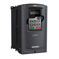
GD310-045P-4-UL
User Manuals: INVT GD310-045P-4-UL Vector Drive
Manuals and User Guides for INVT GD310-045P-4-UL Vector Drive. We have
1
INVT GD310-045P-4-UL Vector Drive manual available for free PDF download: Operation Manual
INVT GD310-045P-4-UL Operation Manual (269 pages)
Brand:
INVT
| Category:
DC Drives
| Size: 9 MB
Table of Contents
Table of Contents
3
Safety Precautions
9
What this Chapter Contains
9
Safety Definition
9
Warning Symbols
9
Safety Guidelines
10
Delivery and Installation
10
Commissioning and Running
11
Maintenance and Replacement of Components
12
What to Do after Scrapping
12
Quick Start-Up
13
What this Chapter Contains
13
Unpacking Inspection
13
Application Confirmation
13
Environment
13
Installation Confirmation
14
Basic Commissioning
14
Product Overview
15
What this Chapter Contains
15
Basic Principles
15
Product Specification
16
Name Plate
18
Type Designation Key
19
Rated Specifications
19
The Vfds of AC 3PH 200V-240V
19
The Vfds of AC 3PH 380V-480V
20
The Vfds of AC 3PH 520V-600V
22
Structure Diagram
22
Installation Guidelines
24
What this Chapter Contains
24
Mechanical Installation
24
Installation Environment
24
Installation Direction
25
Installation Manner
26
Single Installation
27
Multiple Installations
27
Vertical Installation
28
Slanting Installation
29
Standard Wiring
30
Connection Diagram of Main Circuit
30
Terminals Figure of Main Circuit
31
Wiring of Terminals in Main Circuit
35
Wiring Diagram of Control Circuit
36
Terminals of Control Circuit
36
Input /Output Signal Connection Figure
38
Layout Protection
39
Protecting the VFD and Input Power Cable in Short-Circuit Situations
39
Protecting the Motor and Motor Cable in Short-Circuit Situations
39
Protecting the Motor against Thermal Overload
39
Implementing a Bypass Connection
39
Keypad Operation Procedure
40
What this Chapter Contains
40
Keypad
40
Keypad Displaying
42
Displayed State of Stopping Parameter
42
Displayed State of Running Parameters
43
Displayed State of Fault
43
Displayed State of Function Codes Editing
43
Keypad Operation
43
How to Modify the Function Codes of the VFD
44
How to Set the Password of the VFD
44
How to Watch the VFD State through Function Codes
45
Function Parameter
46
What this Chapter Contains
46
Function Parameter List
46
P00 Group Basic Function Group
47
P01 Group Start-Up and Stop Control
54
P02 Group Motor 1
59
P03 Group Vector Control
62
P04 Group SVPWM Control
66
P05 Group Input Terminals
71
P06 Group Output Terminals
78
P07 Group Human-Machine Interface
82
P08 Group Enhanced Function
88
P09 Group PID Control
96
P10 Group Simple PLC and Multi-Step Speed Control
100
P11 Group Protective Parameters
103
P12 Group Motor 2
107
P13 Group Synchronous Motor Control
112
P14 Group Serial Communication
114
P15 Group Profibus/Canopen Function
116
P16 Group Ethernet Function
118
P17 Group Monitoring Function
119
Basic Operation Instruction
122
What this Chapter Contains
122
First Powering on
122
Vector Control
126
SVPWM Control
130
Torque Control
134
Parameters of the Motor
137
Start-Up and Stop Control
142
Frequency Setting
145
Analog Input
150
Analog Output
151
Digital Input
155
Digital Output
161
Simple PLC
164
Multi-Step Speed Running
166
PID Control
168
General Steps of PID Parameters Setting
170
PID Inching
170
Traverse Running
173
Pulse Counter
174
Fixed-Length Control
175
Fault Procedure
176
Fault Tracking
180
What this Chapter Contains
180
Alarm and Fault Indications
180
How to Reset
180
Fault History
180
Fault Instruction and Solution
180
Common Fault Analysis
186
The Motor Does Not Work
186
Motor Vibration
187
Overvoltage
187
Undervoltage Fault
188
Abnormal Heating of the Motor
189
Overheat of the VFD
190
Motor Stall During ACC
190
Overcurrent
191
Maintenance and Hardware Diagnostics
192
What this Chapter Contains
192
Maintenance Intervals
192
Cooling Fan
194
Capacitors
195
Capacitors Reforming
195
Change Electrolytic Capacitors
196
Power Cable
196
Communication Protocol
197
What this Chapter Contains
197
Brief Instruction to Modbus Protocol
197
Application of the VFD
198
Rs485
198
RTU Mode
200
RTU Command Code and Communication Data Illustration
203
Command Code: 03H
203
Command Code: 06H
204
Command Code 08H for Diagnosis
205
Command Code: 10H, Continuous Writing
206
The Definition of Data Address
207
Fieldbus Ratio Values
211
Fault Message Response
212
Example of Writing and Reading
213
Common Communication Fault
217
Appendix A Expansion Card
218
What this Chapter Contains
218
PROFIBUS Expansion Card
218
Product Naming Rules
219
EC-TX-103 Communication Card
219
The Appearance of EC-TX-103 Communication Card
219
Compatible Motor of EC-TX-103 Communication Card
220
Delivery List
220
Installation of EC-TX-103 Communication Card
220
System Configuration
224
PROFIBUS-DP Communication
225
Fault Information
233
Canopen Optional Cards
234
Appendix B Technical Data
235
What this Chapter Contains
235
Ratings
235
Capacity
235
Derating
235
Grid Specifications
236
Motor Connection Data
236
EMC Compatibility and Motor Cable Length
236
Applicable Standards
237
CE Marking
237
UL and CUL Marking
237
Compliance with the European EMC Directive
237
EMC Regulations
237
Category C2
238
Category C3
238
Appendix C Dimension Drawings
239
What this Chapter Contains
239
Keypad Structure
239
Structure Chart
239
Installation Bracket (Optional)
239
VFD Structure
240
Dimensions for Vfds
240
Wall Installation
240
Flange Installation
242
Floor Installation
244
Dimensions for Vfds of AC 3PH 520V(-10%)-600V(+10%)
246
Wall Installation
246
Flange Installation
246
Appendix D Peripheral Options and Parts
247
What this Chapter Contains
247
Peripheral Wiring
247
Power Supply
248
Cables
248
Power Cables
248
Control Cables
249
Routing the Cables
253
Insulation Checking
253
Fuse
254
Reactors
256
Filter
259
Filter Type Instruction
260
Filter Type
260
Braking System
262
Select the Braking Components
262
Selecting the Brake Resistor Cables
266
Placing the Brake Resistor
266
Appendix E Further Information
268
Product and Service Inquiries
268
Feedback on INVT VFD Manuals
268
Documents on the Internet
268
Advertisement
Advertisement
Related Products
INVT GD310-045G-6-UL
INVT GD310-011P-4-UL
INVT GD310-022P-4-UL
INVT GD310-030G-6-UL
INVT GD310-037G-6-UL
INVT GD310-090G-6-UL
INVT GD310-075G-6-UL
INVT GD310-055G-6-UL
INVT GD310-022G-6-UL
INVT GD310-018G-6-UL
INVT Categories
Inverter
DC Drives
Servo Drives
Controller
UPS
More INVT Manuals
Login
Sign In
OR
Sign in with Facebook
Sign in with Google
Upload manual
Upload from disk
Upload from URL