Table of Contents
Advertisement
Quick Links
Advertisement
Chapters
Table of Contents

Related Manuals for Keysight Technologies N5990A


Summary of Contents for Keysight Technologies N5990A
- Page 1 Keysight N5990A MIPI M-PHY Receiver Test User Guide...
- Page 2 THE IMPLIED WARRANTIES OF The license set forth in the EULA represents MERCHANTABILITY AND FITNESS FOR A the exclusive authority by which the U.S. PARTICULAR PURPOSE. KEYSIGHT SHALL government may use, modify, distribute, or Keysight N5990A MIPI M-PHY Receiver Test User Guide...
-
Page 3: Table Of Contents
Oscilloscope Application Supplier Company Name Oscilloscope Bandwidth Starting the N5990A MPHY User Interface Configuring the DUT DUT Parameters Custom HS DR Default Levels Default Timing Default Sequences Special Parameters M8020 ISI Properties Connection Setup Keysight N5990A MIPI M-PHY Receiver Test User Guide... - Page 4 Sequencer Parameters Group Parameters Procedure Parameters 4 Calibrations Calibration Overview Reference Clock Calibration Purpose Procedure Connection Diagram Parameters Dependencies Results Level Calibration Terminated / Into Open Purpose Procedure Connection Diagram Parameters Dependencies Results Keysight N5990A MIPI M-PHY Receiver Test User Guide...
- Page 5 Embedded Fixture ISI (w/Switch) Calibration Purpose Procedure Connection Diagram Parameters Dependencies Results Short Term RJ Calibration Purpose Procedure Connection Diagram Parameters Dependencies Results Low Frequency RJ Calibration Purpose Procedure Connection Diagram Parameters Dependencies Results Keysight N5990A MIPI M-PHY Receiver Test User Guide...
- Page 6 Purpose Procedure Connection Diagram Parameters Dependencies Results SJ Calibration Purpose Procedure Connection Diagram Parameters Dependencies Results Eye Opening Calibration with Jitter/ Eye Opening SigTest Cal Purpose Procedure Connection Diagram Parameters Dependencies Results Keysight N5990A MIPI M-PHY Receiver Test User Guide...
- Page 7 Dependencies Results Inter Pair Skew Calibration Purpose Procedure Connection Diagram Parameters Dependencies Results 5 HS Tests Test 2.1.1- HS-RX Differential Input Vol tage Amplitude Test Purpose Procedure Connection Diagram Parameters Dependencies Results Keysight N5990A MIPI M-PHY Receiver Test User Guide...
-
Page 8: Unipro Test Mode
Procedure Connection Diagram Parameters Dependencies Results Test 2.1.4-HS-RX Differential Termination Enable Time Purpose Procedure Connection Diagram Parameters Dependencies Results Test 2.1.5-HS-RX Differential Termination Disable Time Purpose Procedure Connection Diagram Parameters Dependencies Results Keysight N5990A MIPI M-PHY Receiver Test User Guide... - Page 9 Test 2.1.8-HS-RX Frequency Offset Tolerance (fOFFSET-RX) during HS Burst Purpose Procedure Connection Diagram Parameters Dependencies Results Test 2.1.8b-HS-RX Frequency Offset (fOFFSET-RX) Tolerance during HS-Continuous Mode Test Purpose Procedure Connection Diagram Parameters Dependencies Results Keysight N5990A MIPI M-PHY Receiver Test User Guide...
- Page 10 Test 2.1.10-HS-RX Sync Length Verification Purpose Procedure Connection Diagram Parameters Dependencies Results Jitter Sensitivity Test Purpose Procedure Connection Diagram Parameters Dependencies Results Low Frequency Jitter Sensitivity Test Purpose Procedure Connection Diagram Parameters Dependencies Results Keysight N5990A MIPI M-PHY Receiver Test User Guide...
- Page 11 Results Test 2.4.5-SQ-RX Squelch Noise Pulse Wid th (T PULSE-SQ Purpose Procedure Connection Diagram Parameters Dependencies Results Test 2.4.6-SQ-RX Squelch Noise Pulse Spacing (T SPACE-SQ Purpose Procedure Connection Diagram Parameters Dependencies Results Keysight N5990A MIPI M-PHY Receiver Test User Guide...
- Page 12 Connection Diagram Parameters Dependencies Results Test 2.2.4-PWM-RX Differential Termination Enable Time TERM-ON-PWM-RX) Purpose Procedure Connection Diagram Parameters Dependencies Results Test 2.2.5-PWM-RX Differential Termination Disable Time TERM-OFF-PWM-RX Purpose Procedure Connection Diagram Parameters Dependencies Results Keysight N5990A MIPI M-PHY Receiver Test User Guide...
- Page 13 Test 2.2.7b-PWM-RX Receive Bit Duration Tolerance, During LINE-READ (TOL PWM-G1-LR-RX) Purpose Procedure Connection Diagram Parameters Dependencies Results Test 2.2.8-PWM-RX Receive Ratio PWM-G1 and above PWM-RX Purpose Procedure Connection Diagram Parameters Dependencies Results Keysight N5990A MIPI M-PHY Receiver Test User Guide...
- Page 14 Connection Diagram Parameters Dependencies Results Test 2.3.4-SYS-RX Differential Termination Enable Time TERM-ON-SYS-RX Purpose Procedure Connection Diagram Parameters Dependencies Results Test 2.3.5-SYS-RX Differential Termination Disable Time TERM-OFF-SYS-RX Purpose Procedure Connection Diagram Parameters Dependencies Results Keysight N5990A MIPI M-PHY Receiver Test User Guide...
- Page 15 Purpose Procedure Connection Diagram Parameters Dependencies Results Common Mode Interference Test Purpose Procedure Connection Diagram Parameters Dependencies Results 10 Manual Test Procedures Setup Procedure Full Purpose Procedure Connection Diagram Parameters Dependencies Result Keysight N5990A MIPI M-PHY Receiver Test User Guide...
- Page 16 Setup Procedure Fast Purpose Procedure Connection Diagram Parameters Dependencies Results A Appendix Data Structure and Backup Remote Interface IBerReader Controlling Loop Parameters and Looping Over Selected Tests Unipro Test Mode Unipro Script Generation Keysight N5990A MIPI M-PHY Receiver Test User Guide...
-
Page 17: Introduction
Keysight N5990A MIPI M-PHY Receiver Test User Guide Introduction / 18 Document History / 19 Overview... -
Page 18: Document History
Second Edition (February, 2018) The second edition of this user guide describes functionality of software version 2.0. Third Edition (September, 2018) The third edition of this user guide describes functionality of software version 4.01. Keysight N5990A MIPI M-PHY Receiver Test User Guide... -
Page 19: Overview
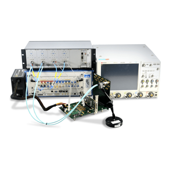
Introduction Overview The Keysight N5990A Test Automation software is an open and flexible framework for automating electrical compliance tests for digital buses such as PCI Express or USB. It is globally marketed and supported by Keysight Technologies as N5990A. The Keysight N5990A for MIPI (Mobile Industry Processor Interface) M-PHY provides the automation of the MIPI M-PHY receiver testing for the physical layer. - Page 20 Introduction Figure 1 MIPI M-PHY Receiver Test Setup Example (for J-BERT M8020A System Configuration) Keysight N5990A MIPI M-PHY Receiver Test User Guide...
- Page 21 Introduction Figure 2 MIPI M-PHY Receiver Test Setup Example (for J-BERT M8010A + DSGA System Configuration) Keysight N5990A MIPI M-PHY Receiver Test User Guide...
- Page 22 Introduction Figure 3 MIPI M-PHY Receiver Test Setup Example (for J-BERT N4903B System Configuration) Keysight N5990A MIPI M-PHY Receiver Test User Guide...
- Page 23 MIPI M-PHY Receiver Test Setup Example (for J-BERT N4903B + DSGA System Configuration) The Keysight N5990A for MIPI M-PHY also provides the automation of the MIPI M-PHY transmitter testing for the physical layer. In this case, the transmitter tests are conducted with the integration of the Keysight U7249E MIPI M-PHY Tx Test Software.
- Page 24 Introduction For oscilloscope Infiniium versions lower than 6,10,00709, the Tests NOTE 1,1,6 and 1,1,7 will not work. Keysight N5990A MIPI M-PHY Receiver Test User Guide...
-
Page 25: N5990A M-Phy Station
Keysight N5990A MIPI M-PHY Receiver Test User Guide N5990A M-PHY Station / 26 N5990A M-PHY Station Configuration / 36 Starting the N5990A MPHY User Interface / 37 Configuring the DUT... -
Page 26: N5990A M-Phy Station Configuration
N5990A M-PHY Station Configuration Refer to the “N5990A Test Automation Software Platform Installation Guide” for instructions on how to install and start the N5990A Test Automation software platform. After the software has been installed, two icons are added to the desktop as shown in... - Page 27 In the Settings section, the following options are available: Database Option In case you have purchased the option N5990A opt. 001, the interface to SQL databases (and web browsers) is available. You can establish a connection to the database application server by clearing the default Database Offline check box and entering the IP address of the server.
- Page 28 M-PHY testing. It contains the following options: 1 System Configuration 2 Separate Low Speed Generator 3 Use Bit-2100 Switch 4 Scope App Provider 5 Oscilloscope bandwidth Figure 7 M-PHY Configuration Window Keysight N5990A MIPI M-PHY Receiver Test User Guide...
-
Page 29: System Configuration
Generator and as Error Detector, if necessary. • It supports Loopback, Offline and Custom BER operation modes. The N4903B stand-alone is not able to operate in UniPro PHY Test Mode and has to be combined with DSGA. Keysight N5990A MIPI M-PHY Receiver Test User Guide... - Page 30 For any receiver or transmitter test configuration, having a DSGA enables sending hardware reset signals to the DUT. This allows seamless transition from one test mode to the next without user intervention. Keysight N5990A MIPI M-PHY Receiver Test User Guide...
-
Page 31: Separated Low Speed Generator
DSGA. Select the Separated Low Speed Generator check box to add DSGA to the system configuration. Refer to “M8020A + DSGA”and “N4903B + DSGA” in the previous section for more details. Keysight N5990A MIPI M-PHY Receiver Test User Guide... -
Page 32: Use Bit-2100 Switch
Two 6:1 switch modules are required for this purpose. In order to use a Keysight 2100 Series Switch System for automated receiver test, the Keysight option 002 (Switch System Support, available from Keysight as BIT-2001-0002-0), is required. Keysight N5990A MIPI M-PHY Receiver Test User Guide... -
Page 33: Oscilloscope Application Supplier Company Name
In case the purchase date is unknown or you are unsure about the software supplier name, open the U7249E software on the Oscilloscope and choose Help > About... in the menu. The About dialog displays the supplier company name. Keysight N5990A MIPI M-PHY Receiver Test User Guide... -
Page 34: Oscilloscope Bandwidth
After the installation process, all instruments are configured by default in Offline mode. In this simulation mode, the hardware does not need to be physically connected to the test controller PC. N5990A cannot connect to any instrument in this mode. In order to control the instruments that are connected to the PC, the instrument address must be entered. - Page 35 4 Click Check Connections to verify that the connections for the instruments are established successfully. If anything is wrong with the Instrument Address, a window is displayed with a message describing the problem. Keysight N5990A MIPI M-PHY Receiver Test User Guide...
-
Page 36: Starting The N5990A Mphy User Interface
N5990A M-PHY Station Starting the N5990A MPHY User Interface Double click the N5990A MPHY icon that appears on the desktop (see Figure 9). Alternatively, go to Start > All Programs > BitifEye > MPHY > ValiFrame MPHY. Figure 9 N5990A MPHY Icon... -
Page 37: Configuring The Dut
Receiver/Transmitter test configuration. The selected parameters are later used in the calibration and test procedures shown in the N5990A main window. Figure 11 Configure DUT Panel for Receiver Keysight N5990A MIPI M-PHY Receiver Test User Guide... - Page 38 N5990A M-PHY Station Figure 12 Configure DUT Panel for Transmitter Keysight N5990A MIPI M-PHY Receiver Test User Guide...
- Page 39 N5990A M-PHY Station Figure 13 Configure DUT panel (for the database connection) If you select the Database Offline option in the N5990A M-PHY Station Configuration window (see Figure 6), the Configure DUT panel appears as shown in Figure 13. To configure the DUT with a database connection, do the following: 1 Enter values (any) for Product Number and Serial Number.
-
Page 40: Dut Parameters
Compliance Mode In this mode, the tests are conducted as mandated by the CTS, the test parameters used in the calibration and test procedures are shown but cannot be modified by the user. Keysight N5990A MIPI M-PHY Receiver Test User Guide... - Page 41 “Default Timing” for more details. Default Sequences Brings up a dialog where the HS, LS, and Squelch sequence files can be selected. Refer to “Default Sequences” for more details. Receiver Test Configuration Keysight N5990A MIPI M-PHY Receiver Test User Guide...
- Page 42 Properties” section. Transmitter Test Configuration Test Group LA_RT Selecting the check box will add the test procedures for the respective group in the N5990A, whereas SA_RT • RT: TX connection is resistively terminated • NT: TX connection is non-terminated (into-open) LA_NT •...
-
Page 43: Custom Hs Dr
For the selected Ref. Clock Frequency, the Custom Data Rate is calculated as a multiple of the reference clock. Ref. Clock Frequency It can be set to 19.2 MHz, 26MHz, 38.4MHz or 52MHz. Keysight N5990A MIPI M-PHY Receiver Test User Guide... -
Page 44: Default Levels
Click Default Levels in the Configure DUT Panel to display the Set M-PHY Default Levels window (see Figure 15). It allows the levels (Amplitude and Offset) for the Data, DSGA and Reference Clock channels to be set. Figure 15 Set M-PHY Default Levels panel Keysight N5990A MIPI M-PHY Receiver Test User Guide... -
Page 45: Default Timing
HS Sequence (Burst), HS Sequence (Cont), LS Sequence (Burst) and Squelch Sequence test groups. HS implies High Speed NOTE LS implies Low Speed Cont implies Continuous Sync Pattern The D10.5 and D26.5 symbols are used as default for sync pattern. Keysight N5990A MIPI M-PHY Receiver Test User Guide... - Page 46 UniPro Test Mode (see , “Unipro Script Generation for more details). The step to generate UniPro Scripts is necessary only for this test mode NOTE and requires a license for option 167. Keysight N5990A MIPI M-PHY Receiver Test User Guide...
- Page 47 A wildcard is an expression or symbol that is used especially to represent any value when selecting specific file names or directories. This section refers to the wildcard’s availability in the N5990A M-PHY for the sequence file names selected in the Select M-PHY Sequences panel (see Figure 17).
-
Page 48: Special Parameters
An Example of A Wildcard Sequence For the GearX-A tests, the sequence file name appears as NOTE MphyComplianceGearXA.seq. If the GearX-A appears with "-" (dash), N5990A does not recognize the sequence file and displays an error. Special Parameters Click Special Parameters (See Figure... - Page 49 DUT receives the data properly. This can be achieved by reading pass / fail information from the device. The Bit Error Ratio (BER) is measured and read. N5990A supports four different BER Reader implementations: 1 Bert Analyzer 2 Offline BER Reader...
- Page 50 BERT generator, the computer BER will be high and the test will fail, even if the returned test pattern matches the original pattern. Offline BER Reader For each step of the test procedure, N5990A shows pop-up dialogs (see Figure 20, to Figure 22) requesting you to reset and initialize the device and decide whether the device is working properly.
- Page 51 The DUT is configured to Test Mode and Frame and Error counter requests are interleaved with the test pattern. N5990A then decodes the responses captured with the test equipment and calculates the BER. For more details about UniPro Test Mode refer to “Unipro Test...
- Page 52 Single-Ended mode allows you to connect the Tx- to the DSGA and Tx+ to the scope and verify that the DUT is working, by using the scope decoder. Calibrations Files Directory Browse Keysight N5990A MIPI M-PHY Receiver Test User Guide...
- Page 53 Property panel of the main windows when selecting the desired Terminated Mode group in the test procedure tree (see Figure 25). Figure 24 CDR Loop Bandwidth for G1 Keysight N5990A MIPI M-PHY Receiver Test User Guide...
- Page 54 N5990A M-PHY Station Figure 25 Modify CDR Loop Bandwidth for each gear Keysight N5990A MIPI M-PHY Receiver Test User Guide...
- Page 55 If you select the check box for Setup procedure in each test subgroup, the Setup Procedure Pattern is available for each test sub group in the N5990A User Interface, allowing you to configure the DUT before tests are started. Use De-emphasis If you select the check box for Use De-emphasisis, the generator will send de-emphasized signals.
- Page 56 For more details about the external clock refer to the “J-BERT 4903B” and “J-BERT M8020A” manuals, respectively. The N5990A allows an external reference clock source to be used but it is NOTE not responsible for its setup. Manual break at the sequence start If selected, the sequence will start with a manual break.
- Page 57 Note that the time is halved, but two sets of TTCs and ISI traces are required (see Figure 27). Figure 26 Test Tree for Individually Lane Mode (up) and for Simultaneously Lane Mode (down) Keysight N5990A MIPI M-PHY Receiver Test User Guide...
-
Page 58: M8020 Isi Properties
Connection Diagram for Simultaneously Lane Test Mode M8020 ISI Properties This dialog allows to configure the ISI generation when M8020 is selected as system configuration in the Station Configuration window (see Figure Keysight N5990A MIPI M-PHY Receiver Test User Guide... - Page 59 Insertion Loss Offset: It is the insertion loss at 0Hz. • Frequency 1: First frequency point. • Insertion Loss 1: Insertion loss applied to the first frequency point. • Frequency 2: Second frequency point. Keysight N5990A MIPI M-PHY Receiver Test User Guide...
-
Page 60: Connection Setup
1 Probing Method: It can be selected as: • Active Probe (Differential Probe) • Active Probe (Active Termination Adapter) • Active Probe (Active Termination Adapter)[Manual] • Direct Connect 2 Connection Type: It can be selected as: • Single-Ended Keysight N5990A MIPI M-PHY Receiver Test User Guide... - Page 61 Depending on the selection of Connection Type, the relative block (Single-Ended or Differential) is enabled and it allows you to select channels with the Primary Lane and Secondary Lane (see Figure 29). Keysight N5990A MIPI M-PHY Receiver Test User Guide...
-
Page 63: Calibrations And Test Procedures
As a safety feature, all calibration and test results are saved by default to the N5990A “Tmp” directory (refer to the “Keysight N5990A Test Automation Software Platform Installation Guide”). The sub-folder Results/M-PHY Station contains the Excel files of the final results measured at each calibration and test procedure. - Page 64 Calibrations and Test Procedures files are saved by default to the N5990A calibrations folder. If these calibrations are run again, the data file will be overwritten. In order to save the calibration data files at each configuration, you must copy the files from the directory: C:\ProgramData\BitifEye\N5990A\Calibrations\MPHY and save them manually in any folder before re-running the calibrations.
-
Page 65: Example Of Mipi M-Phy Calibration / Test Procedure
Figure 30, the Level Calibration Into Open is highlighted as an example. The respective parameters are shown on the right side of the N5990A User Interface. This is achieved by clicking on the calibration/test name. To start one or more procedures, do the following: 1 Select the check box for the corresponding procedure. - Page 66 Offline mode, that is, without any instrument connected. The Offline mode is intended for product demonstrations with simulated data. CALIBRATIONS RUN IN OFFLINE MODE DO NOT GENERATE VALID CALIBRATION DATA. Keysight N5990A MIPI M-PHY Receiver Test User Guide...
-
Page 67: Connection Diagram
In this case, the J-BERT M8020A system allows to connect 1,2,3 or 4 data channels and the J-BERT N4903B 1 or 2 data channels. Figure 32 shows the data channels for the M8020A and Figure 33 for the N4903B. Keysight N5990A MIPI M-PHY Receiver Test User Guide... -
Page 68: Multichannel With Switch
Output Data 0 of the data generator is used and must be connected to the matrix input. In the connection diagram the switch is represented as a red box between the generator data output and the Rx DUT input (see Figure 34). Keysight N5990A MIPI M-PHY Receiver Test User Guide... - Page 69 Calibrations and Test Procedures Figure 34 Connection Diagram with Switch Click Show Switch Connections (see Figure 34) to display the switch connections in detail (see Figure 35). Keysight N5990A MIPI M-PHY Receiver Test User Guide...
- Page 70 If the "Use Switch" option is selected and the "Separated Low Speed Generator" not, the switch will be used for multi-lane purposes and the connections for more than one lane must to be done as explained in the Multichannel with Switch section. Keysight N5990A MIPI M-PHY Receiver Test User Guide...
-
Page 71: Result Description
In this example, the first half indicates that the procedure passed successfully at the present run and the second half means that it was not completely run at the previous run. Keysight N5990A MIPI M-PHY Receiver Test User Guide... -
Page 72: Mipi M-Phy Parameters
N5990A. One of them, Repetitions, is available for all procedures and groups in the procedure tree. The others are only available for procedures. Like all other parameters the sequencer parameters are shown on the right side of the N5990A user interface and you can change them (see Figure 36). - Page 73 Abort Sequence - Abort the execution of the sequence. Repetitions The number of times the group or procedure is going to be repeated. If the value is '0', it runs only once. Keysight N5990A MIPI M-PHY Receiver Test User Guide...
-
Page 74: Group Parameters
Group Parameters Group parameters are used for several related calibration or test procedures. They are shown on the right side of the N5990A user interface when the selected entry of the procedure tree on the left is a group instead of an individual procedure. - Page 75 Specify the value of the trigger level used for triggering the test signal when running the M-PHY tests. The value of this option will be used ONLY when the "Threshold Mode" option is set to "Manual". By default, it is set to 0V. Keysight N5990A MIPI M-PHY Receiver Test User Guide...
-
Page 76: Procedure Parameters
Procedure Parameters are parameters that do not fall into one of the previously described categories. They are shown on the right side of the N5990A user interface when the selected entry of the procedure tree on the left is an individual procedure. They only change the behavior of that single procedure. - Page 77 It is the higher limit for the tested RF (Radio Frequency) Interference. If the minimum and maximum interference values are equal, only one interference level is tested. Max Jitter Value It is the maximum jitter value to be calibrated. Keysight N5990A MIPI M-PHY Receiver Test User Guide...
- Page 78 It is the frequency value of PJ. (HS/LS) Prepare Length It defines the PREPARE sub-state. It specifies the number of DIFP (Differential Positive Pulse) states before the HS/LS-burst starts. It must be specified in SI (1SI = 10UI). Keysight N5990A MIPI M-PHY Receiver Test User Guide...
- Page 79 It can be selected as “True”/”False” to switch between real time eye and single waveform. The measurement time increases by viewing the real time eye. Sleep Length It is the provided sleep length value (it is the power saving state between LS Bursts). Keysight N5990A MIPI M-PHY Receiver Test User Guide...
- Page 80 Infiniisim Transfer Function instead of a replica channel, set the “Use InfiniiSim” parameter to Transfer Function Chan2 “True” and copy the Transfer Function file to the scope, either under “C:\Users\Public\Public Documents\ Infiniium\Filters\M-PHY” or “C\Documents and Settings\All Users\Documents\Infiniium\Filters\M-PHY”. Keysight N5990A MIPI M-PHY Receiver Test User Guide...
-
Page 81: Calibrations
Keysight N5990A MIPI M-PHY Receiver Test User Guide Calibrations Calibration Overview / 82 Reference Clock Calibration / 83 Level Calibration Terminated / Into Open / 90 ISI (w/Switch) Calibration / 99 Embedded Fixture ISI (w/Switch) Calibration / 104 Short Term RJ Calibration... -
Page 82: Calibration Overview
LP and HS level calibrations and the inter-pair skew calibration. Calibrations for all hardware configurations are explained in the following sections. Keysight N5990A MIPI M-PHY Receiver Test User Guide... -
Page 83: Reference Clock Calibration
The Reference Clock Calibration is available for all hardware configurations (see Figure 38). Figure 38 Reference Clock Calibration Purpose This procedure calibrates the output levels (Amplitude and Offset) of the reference clock. Keysight N5990A MIPI M-PHY Receiver Test User Guide... -
Page 84: Procedure
The results are saved in two separate calibration data files, one for the offset and one for the amplitude values. Connection Diagram Figure 39 Figure 40 show the connection diagrams for different system configurations. Figure 39 Connection Diagram for Reference Clock Calibration (for M8020A) Keysight N5990A MIPI M-PHY Receiver Test User Guide... -
Page 85: Parameters
A calibration data graph. • The common parameter list (in Expert Mode). • A data table for the offset and amplitude that are being calibrated. (Refer to Table 7 for the parameter description). Keysight N5990A MIPI M-PHY Receiver Test User Guide... - Page 86 Calibrations Keysight N5990A MIPI M-PHY Receiver Test User Guide...
- Page 87 Calibrations Figure 41 Example HTML Viewer for Offset in Reference Clock Calibration Keysight N5990A MIPI M-PHY Receiver Test User Guide...
- Page 88 Calibrations Keysight N5990A MIPI M-PHY Receiver Test User Guide...
- Page 89 It is the effective offset value as measured using a DSO with the histogram measurement. Set Amplitude It is the set amplitude value for a given step. Measured Amplitude It is the effective amplitude value as measured using a DSO with the histogram measurement. Keysight N5990A MIPI M-PHY Receiver Test User Guide...
-
Page 90: Level Calibration Terminated / Into Open
This calibration should run once at each selected lane (see Figure 43). For the M8020A/N4903B + DSGA setup, the calibration for Data0 includes the switch. If more than one channel is selected, the other data outputs are calibrated without switch. Keysight N5990A MIPI M-PHY Receiver Test User Guide... -
Page 91: Procedure
The connection diagrams shown are for Gear1. They are the same for NOTE Gear2, Gear3 and Gear4 but vary in the TTC value (G1: 250ps; G2: 125ps; G3 and G4: 60ps). Figure 44 Connection Diagram for Level Calibration (for M8020A) Keysight N5990A MIPI M-PHY Receiver Test User Guide... - Page 92 Calibrations Figure 45 Connection Diagram for Level Calibration (for M8020A + DSGA ) Figure 46 Connection Diagram for Level Calibration (for N4903B) Keysight N5990A MIPI M-PHY Receiver Test User Guide...
- Page 93 Calibrations Figure 47 Connection Diagram for Level Calibration, Into Open Data 0 (for N4903B +DSGA) Figure 48 Connection Diagram for Level Calibration, Into Open Data 0 (for M8020A) Keysight N5990A MIPI M-PHY Receiver Test User Guide...
- Page 94 Calibrations Figure 49 Connection Diagram for Level Calibration, Into Open Data 0 (for M8020A + DSGA) Figure 50 Connection Diagram for Level Calibration, Into Open Data 0 (for N4903B) Keysight N5990A MIPI M-PHY Receiver Test User Guide...
-
Page 95: Parameters
Offset Range • Use Infiniisim • Transfer Function Chan • Filter Delay Chan1 • Max. Time Span Chan1 These parameters are listed in Table Dependencies No calibration is required for this procedure. Keysight N5990A MIPI M-PHY Receiver Test User Guide... -
Page 96: Results
53. The results comprise of the following: • A calibration data graph. • The common parameter list (in Expert Mode). • A data table for the offset and amplitude that are being calibrated (Refer to Table Keysight N5990A MIPI M-PHY Receiver Test User Guide... - Page 97 Example HTML Viewer for Levels Calibration Offset Terminated or Into Open Figure 53 Example HTML Viewer for Levels Calibration Amplitude Terminated or Into Open Table 8 Levels Calibration Amplitude Terminated / Into Open data table Keysight N5990A MIPI M-PHY Receiver Test User Guide...
- Page 98 It is the effective offset value as measured using a DSO with the histogram measurement. Set Amplitude It is the set amplitude value for a given step. Measured Amplitude It is the effective amplitude value as measured using a DSO with the histogram measurement. Keysight N5990A MIPI M-PHY Receiver Test User Guide...
-
Page 99: Isi (W/Switch) Calibration
M-PHY specification. This procedure calibrates the ISI of the trace used for that purpose. This calibration should run once at each data rate (see Figure 54). Keysight N5990A MIPI M-PHY Receiver Test User Guide... -
Page 100: Procedure
The connection diagrams shown are for Gear1. They are the same for NOTE Gear2 and Gear 3, but vary in the TTC value (G1: 250ps; G2: 125ps; G3 and G4: 60ps). Figure 55 Connection Diagram for ISI Calibration (for M8020A) Keysight N5990A MIPI M-PHY Receiver Test User Guide... - Page 101 Calibrations Figure 56 Connection Diagram for ISI Calibration (for M8020A + DSGA) Figure 57 Connection Diagram for ISI Calibration (for J-BERT) Keysight N5990A MIPI M-PHY Receiver Test User Guide...
-
Page 102: Parameters
Jitter Calibration File • Use Infiniisim • Transfer Function Chan • Filter Delay Chan2 • Max Time Span Chan2 These parameters are listed in Table Dependencies No procedure is required for this calibration. Keysight N5990A MIPI M-PHY Receiver Test User Guide... -
Page 103: Results
"Pass"/"Fail" - If it is "Fail", the measured or obtained values are not monotonic. Data Rate HS data rate at which the ISI was calibrated. Measured Offset It is the measured value of ISI. Keysight N5990A MIPI M-PHY Receiver Test User Guide... -
Page 104: Embedded Fixture Isi (W/Switch) Calibration
M-PHY specification. This procedure calibrates the ISI when it is generated with the embedded M8020A ISI fixture and is selected as Automatic (see M8020 ISI Properties on page 58). Keysight N5990A MIPI M-PHY Receiver Test User Guide... -
Page 105: Procedure
“Step Size” until the “Target ISI Value” is reached. Connection Diagram Refer to the connection diagrams shown in Figure 60 Figure Figure 60 Connection Diagram for Embedded ISI Calibration (for M8020A) Keysight N5990A MIPI M-PHY Receiver Test User Guide... -
Page 106: Parameters
• Step Size • Accuracy of the Calibration • Transitions • Use Infiniisim • Transfer Function Chan2 • Filter Delay Chan2 • Max Time Span Chan2 These parameters are listed in Table Keysight N5990A MIPI M-PHY Receiver Test User Guide... -
Page 107: Dependencies
62. The results comprise of the following: • A calibration data graph. • The common parameter list (in Expert Mode). • A data table for the ISI that is being calibrated (Refer to Table 10). Keysight N5990A MIPI M-PHY Receiver Test User Guide... - Page 108 It is the ISI measured at each step. Set Insertion Loss of Point 2 (dB) The insertion loss that the M8020A sets in the second frequency point. Frequency of Point 2 The frequency of the second point. Keysight N5990A MIPI M-PHY Receiver Test User Guide...
-
Page 109: Short Term Rj Calibration
This calibration should run once at each HS-G1/G2 data rate (see Figure 63). For spec 4.1. this calibration is only mandatory for B-series (for A-series the procedure is shown in the test tree as informative). Keysight N5990A MIPI M-PHY Receiver Test User Guide... -
Page 110: Procedure
Use Infiniisim • Transfer Function Chan • Filter Delay Chan2 • Max Time Span Chan2 These parameters are listed in alphabetical order in Table Dependencies No calibration is required for this procedure. Keysight N5990A MIPI M-PHY Receiver Test User Guide... -
Page 111: Results
64. The results comprise of the following: • A calibration data graph. • The common parameter list (in Expert Mode). • A data table for the random jitter that is being calibrated (Refer to Table 11). Keysight N5990A MIPI M-PHY Receiver Test User Guide... - Page 112 "Pass"/"Fail" - If the set-up is wrong, the calibration procedure fails due to the non-monotonic values measured. Set Jitter It is the set value for the high frequency random jitter. Measured Jitter It is the measured value of the random jitter at each HS data rate. Keysight N5990A MIPI M-PHY Receiver Test User Guide...
-
Page 113: Low Frequency Rj Calibration
This calibration should be run once at each HS-G1/G2 data rate (see Figure 65). For spec 4.1, this calibration is only mandatory for B-series (for A-series, the procedure is shown in the test tree as informative). Keysight N5990A MIPI M-PHY Receiver Test User Guide... -
Page 114: Procedure
Use Infiniisim • Transfer Function Chan2 • Filter Delay Chan2 • Max Time Span Chan2 These parameters are listed in Table Dependencies The procedure required for this method is Short Term RJ Calibration. Keysight N5990A MIPI M-PHY Receiver Test User Guide... -
Page 115: Results
66. The results comprise of the following: • A calibration data graph. • The common parameter list (in Expert Mode). • A data table for the random jitter that is being calibrated. Keysight N5990A MIPI M-PHY Receiver Test User Guide... - Page 116 "Pass"/"Fail" - If the set-up is wrong, the calibration procedure fails due to the non-monotonic values measured. Set Jitter It is the set value for the low frequency random jitter. Measured Jitter It is the measured value of the random jitter. Keysight N5990A MIPI M-PHY Receiver Test User Guide...
-
Page 117: Rj Calibration
This calibration should be run once at each HS-G3 data rate (see Figure 67). For spec 4.1. this calibration is only mandatory for B-series (for A-series, the procedure is shown in the test tree as informative). Keysight N5990A MIPI M-PHY Receiver Test User Guide... -
Page 118: Procedure
Scope RJrms • Use Infiniisim • Transfer Function Chan2 • Filter Delay Chan2 • Max Time Span Chan2 These parameters are listed in Table Dependencies No calibration is required for this procedure. Keysight N5990A MIPI M-PHY Receiver Test User Guide... -
Page 119: Results
68. The results comprise of the following: • A calibration data graph. • The common parameter list (in Expert Mode). • A data table for the random jitter that is being calibrated. Keysight N5990A MIPI M-PHY Receiver Test User Guide... - Page 120 "Pass"/"Fail" - If the set-up is wrong, the calibration procedure fails due to the non-monotonic values measured. Set Jitter It is the set value for the random jitter. Measured Jitter It is the measured value of the random jitter. Keysight N5990A MIPI M-PHY Receiver Test User Guide...
-
Page 121: High Frequency Sj Calibration
This calibration should be run once at each selected HS data rate. For spec 4.1, this calibration is only mandatory for B-series (for A-series, the procedure is shown in the test tree as informative). Keysight N5990A MIPI M-PHY Receiver Test User Guide... -
Page 122: Procedure
Additional Jitter Frequencies (MHz) • Jitter Calibration File • Use Infiniisim • Transfer Function Chan2 • Filter Delay Chan2 • Max Time Span Chan2 These parameters are listed in alphabetical order in Table Keysight N5990A MIPI M-PHY Receiver Test User Guide... -
Page 123: Dependencies
Figure 70. The results comprise of the following: • A calibration data graph. • The common parameter list (in Expert Mode). • A data table for the SJ that is being calibrated. Keysight N5990A MIPI M-PHY Receiver Test User Guide... - Page 124 "Pass"/"Fail" - If the set-up is wrong, the calibration procedure fails due to the non-monotonic values measured. Jitter Frequency It is the value of calibrated jitter frequency. Set SJ It is the measured value for the set SJ value and SJ frequency combination. Keysight N5990A MIPI M-PHY Receiver Test User Guide...
-
Page 125: Sj Calibration
This calibration is run once at each selected HS data rate (see Figure 71). For spec 4.1, this calibration is only mandatory for B-series (for A-series, the procedure is shown in the test tree as informative). Keysight N5990A MIPI M-PHY Receiver Test User Guide... -
Page 126: Procedure
Additional Jitter Frequencies (MHz) • Jitter Calibration File • Use Infiniisim • Transfer Function Chan2 • Filter Delay Chan2 • Max Time Span Chan2 These parameters are listed in alphabetical order in Table Keysight N5990A MIPI M-PHY Receiver Test User Guide... -
Page 127: Dependencies
72. The results comprise of the following: • A calibration data graph. • The common parameter list (in Expert Mode). • A data table for the SJ that is being calibrated (Refer to Table 15). Keysight N5990A MIPI M-PHY Receiver Test User Guide... - Page 128 "Pass"/"Fail" - If the set-up is wrong, the calibration procedure fails due to the non-monotonic values measured. Jitter Frequency It is the value of calibrated jitter frequency. Set SJ It is the measured value for the set SJ value and SJ Frequency combination. Keysight N5990A MIPI M-PHY Receiver Test User Guide...
-
Page 129: Eye Opening Calibration With Jitter/ Eye Opening Sigtest Cal
This calibration is run once at each selected HS data rate (see Figure 73). For spec 4.1, this calibration is only mandatory for B-series (for A-series, the procedure is shown in the test tree as informative). Keysight N5990A MIPI M-PHY Receiver Test User Guide... -
Page 130: Procedure
The parameters used in Expert Mode for this calibration, are as follows: • Lane Under Test Termination Mode • Oscilloscope Bandwidth • Jitter Frequencies • Eye Width Target • Eye Width Max Variation • Eye Height Target Keysight N5990A MIPI M-PHY Receiver Test User Guide... -
Page 131: Dependencies
75. The results comprise of the following: • A calibration data graph. • The common parameter list (in Expert Mode). • A data table for the differential voltage amplitude that is being calibrated (Refer to Table 16). Keysight N5990A MIPI M-PHY Receiver Test User Guide... - Page 132 Calibrations Figure 74 Example HTML Viewer for Eye Opening Width Keysight N5990A MIPI M-PHY Receiver Test User Guide...
- Page 133 It is the set value for voltage amplitude. Eye Height It is the measured value of eye height according to the set voltage. Maximum V_diff_ac_tx It is the maximum measured value of the differential voltage amplitude. Keysight N5990A MIPI M-PHY Receiver Test User Guide...
-
Page 134: Accumulated Voltage Calibration Terminated
When the DSGA is used, two calibrations are required for each data rate: one for Data0 and another one for the other channels. The calibration for Data0 includes the switch. For other channels, Data1 is calibrated without the switch. Keysight N5990A MIPI M-PHY Receiver Test User Guide... -
Page 135: Procedure
• Number of Histogram Hits • Total Jitter • SI (p-p) • Minimum Accumulated Differential Voltage • Use Infiniisim • Transfer Function Chan2 • Filter Delay Chan2 • Max Time Span Chan2 Keysight N5990A MIPI M-PHY Receiver Test User Guide... -
Page 136: Dependencies
• A calibration data graph. • The common parameter list (in Expert Mode). • A data table for the differential voltage amplitude that is being calibrated (Refer to Table 17). Keysight N5990A MIPI M-PHY Receiver Test User Guide... - Page 137 It is the set value for differential amplitude voltage. Measured Eye Opening It is the measured value of eye opening according to the set differential voltage. Maximum V_diff_ac_tx It is the allowed maximum accumulated voltage value according to the specification. Keysight N5990A MIPI M-PHY Receiver Test User Guide...
-
Page 138: Isi Calibration (J20)
This calibration is available only when the N4903B J-BERT with option J20 is connected online. Figure 78 ISI Calibration (J20) Purpose This procedure calibrates the ISI. This calibration should be run once for each data rate selected. Keysight N5990A MIPI M-PHY Receiver Test User Guide... -
Page 139: Procedure
"Jitter can not be measured". Connection Diagram Refer to Figure 79 for the connection diagram. Figure 79 Connection Diagram for ISI J-20 Calibration Keysight N5990A MIPI M-PHY Receiver Test User Guide... -
Page 140: Parameters
HS Sequence File • Show Real Time Eye • Use Infiniisim • Transfer Function Chan2 • Filter Delay Chan2 • Max Time Span Chan2 These parameters are listed in alphabetical order in Table Keysight N5990A MIPI M-PHY Receiver Test User Guide... -
Page 141: Dependencies
81. The results comprise of the following: • A calibration data graph. • The common parameter list (in Expert Mode). • A data table for the ISI that is being calibrated (Refer to Table 18). Keysight N5990A MIPI M-PHY Receiver Test User Guide... - Page 142 "Pass"/"Fail" - If the set-up is wrong, the calibration procedure fails due to the non-monotonic values measured. ISI Trace It is the number of ISI traces. Measured ISI It is the measured value of the ISI. Maximum TJ It is the measured value of the total jitter. Keysight N5990A MIPI M-PHY Receiver Test User Guide...
-
Page 143: Inter Pair Skew Calibration
It is only available for the J-BERT M8020A system. It is required when the number of channels selected in the Special Parameters dialog (see Figure 19) is greater than one. Figure 82 Inter Pair Skew Calibration Purpose It calibrates the inter channel timing behavior. Keysight N5990A MIPI M-PHY Receiver Test User Guide... -
Page 144: Procedure
The skew is measured and calibrated iteratively until its value is smaller than the specification conformance limit. Connection Diagram Figure 83 Figure 84 show the connection diagram. Figure 83 Connection Diagram for Inter Pair Skew Calibration (for M8020A) Keysight N5990A MIPI M-PHY Receiver Test User Guide... -
Page 145: Parameters
Figure 85. The results comprise of the following: • The common parameter list (in Expert Mode). • A data table for the skew that is being calibrated (Refer to Table 19). Keysight N5990A MIPI M-PHY Receiver Test User Guide... - Page 146 "Pass"/"Fail" - If the set-up is wrong, the calibration procedure fails due to the non-monotonic values measured. Lane It is the lane to be calibrated. Skew Value It is the skew value of the lane with respect to Data0. Keysight N5990A MIPI M-PHY Receiver Test User Guide...
-
Page 147: Hs Tests
Keysight N5990A MIPI M-PHY Receiver Test User Guide HS Tests Test 2.1.1- HS-RX Differential Input Voltage Amplitude Test / 149 Test 2.1.2-HS-RX Accumulated Differential Input Voltage Tolerance Test / 156 Test 2.1.3-HS-RX Common Mode Input Voltage Tolerance Test / 162 Test 2.1.4-HS-RX Differential Termination Enable Time... - Page 148 These are applicable to HS-RX, PWM-RX and SYS-RX devices. According to the MIPI M-PHY specification, the HS tests are run with a 100 Ohm differential termination, while the PWM and SYS tests run Into Open. Keysight N5990A MIPI M-PHY Receiver Test User Guide...
-
Page 149: Test 2.1.1- Hs-Rx Differential Input Voltage Amplitude Test
This procedure is available for all hardware configurations. Figure 86 Test 2.1.1-HS-RX Differential Input Voltage Amplitude Test Purpose It verifies that the M-RX is able to receive HS data successfully with the values according to the specification. DIF-RX Keysight N5990A MIPI M-PHY Receiver Test User Guide... -
Page 150: Procedure
The connection diagrams shown are for Gear1. They are the same for NOTE Gear2 and Gear3 but vary in the TTC value (G1: 250ps; G2: 125ps; G3 and G4: 60ps). Keysight N5990A MIPI M-PHY Receiver Test User Guide... - Page 151 HS Tests Figure 87 Connection Diagram for Receiver Tests (for M8020A) Figure 88 Connection Diagram for Receiver Test (for M8020A + DSGA) Keysight N5990A MIPI M-PHY Receiver Test User Guide...
- Page 152 HS Tests Figure 89 Connection Diagram for Receiver Tests (for N4903B) Keysight N5990A MIPI M-PHY Receiver Test User Guide...
-
Page 153: Parameters
CDR Transition Density (if CDR is selected in the Special Parameter dialog, see “BERT Analyzer Settings”) • CDR Loop Order (if CDR is selected in the Special Parameter dialog, “BERT Analyzer Settings”) • Target BER • IBerReader Init Mode • Test Sequence Keysight N5990A MIPI M-PHY Receiver Test User Guide... -
Page 154: Dependencies
• The common parameter list (in Expert Mode) • A test data table (Refer to Table 20). Figure 91 Example HTML Viewer for Test 2.1.1-HS-Rx Differential Input Voltage Am- plitude Test Keysight N5990A MIPI M-PHY Receiver Test User Guide... - Page 155 Max Spec Amplitude It is the maximum differential voltage amplitude value, where the DUT must work according to the specification. Error Count It is the number of errors observed by the DUT. Keysight N5990A MIPI M-PHY Receiver Test User Guide...
-
Page 156: Test 2.1.2-Hs-Rx Accumulated Differential Input Voltage Tolerance Test
It is available for all hardware configurations. Figure 92 Test 2.1.2-HS-RX Accumulated Differential Input Voltage Tolerance Test Purpose It determines that the M-RX receives the HS-Burst successfully with the requirements for V values. DIF-ACC-RX Keysight N5990A MIPI M-PHY Receiver Test User Guide... -
Page 157: Procedure
The connection diagrams shown are for Gear1. They are the same for NOTE Gear2 and Gear3, but vary in the TTC value (G1: 250ps; G2: 125ps; G3 and G4: 60ps). Keysight N5990A MIPI M-PHY Receiver Test User Guide... - Page 158 HS Tests Figure 93 Connection Diagram for Receiver Tests with ISI Trace (for M8020A) Figure 94 Connection Diagram for Receiver Tests with ISI Trace (for M8020 + DSGA) Keysight N5990A MIPI M-PHY Receiver Test User Guide...
- Page 159 HS Tests Figure 95 Connection Diagram for Receiver Tests with ISI Trace (for N4903B) Figure 96 Connection Diagram for Receiver Tests with ISI Trace (for N4903B + DSGA) Keysight N5990A MIPI M-PHY Receiver Test User Guide...
-
Page 160: Parameters
Differential Input Voltage Tolerance Test procedure is shown in Figure The results comprise of the following: • The common parameter list (in Expert Mode) • A test data table (Refer to Table Keysight N5990A MIPI M-PHY Receiver Test User Guide... - Page 161 It is the common mode voltage value to be tested. Min Spec Accumulated Voltage It is the minimum value of the accumulated differential voltage, where the DUT must work according to the specification. Keysight N5990A MIPI M-PHY Receiver Test User Guide...
-
Page 162: Test 2.1.3-Hs-Rx Common Mode Input Voltage Tolerance Test
It is available for all hardware configurations. Figure 98 Test 2.1.3-HS-RX Common Mode Input Voltage Tolerance Test Purpose To determine that the M-RX is able to receive the HS data with the specified values of V CM-RX Keysight N5990A MIPI M-PHY Receiver Test User Guide... -
Page 163: Procedure
CDR Transition Density (if CDR is selected in the Special Parameter dialog, see “BERT Analyzer Settings”) • CDR Loop Order (if CDR is selected in the Special Parameter dialog, “BERT Analyzer Settings”) • Target BER • IBerReader Init Mode Keysight N5990A MIPI M-PHY Receiver Test User Guide... -
Page 164: Dependencies
An example of a HTML Viewer for the Test 2.1.3-HS-RX Common-Mode Input Voltage Tolerance Test procedure is shown in Figure 99. The results comprise of the following: • The common parameter list (in Expert Mode) • A test data table Keysight N5990A MIPI M-PHY Receiver Test User Guide... - Page 165 Max Spec Offset It is the maximum common mode voltage value, where the DUT must work according to the specification. Error Count It is the number of error bits observed by the DUT. Keysight N5990A MIPI M-PHY Receiver Test User Guide...
-
Page 166: Test 2.1.4-Hs-Rx Differential Termination Enable Time
It is available for all hardware configurations. Figure 100 Test 2.1.4-HS-RX Differential Termination Enable Time Purpose It verifies that the HS-RX is able to properly enable its termination within the required time. Keysight N5990A MIPI M-PHY Receiver Test User Guide... -
Page 167: Procedure
The connection diagrams shown are for Gear1. They are the same for NOTE Gear2 and Gear3 but vary in the TTC value (G1: 250ps; G2: 125ps; G3 and G4: 60ps). Keysight N5990A MIPI M-PHY Receiver Test User Guide... - Page 168 HS Tests Figure 101 Connection Diagram for Receiver Tests with Differential Termination (for M8020A) Figure 102 Connection Diagram for Receiver Tests with Differential Termination (for M8020A + DSGA) Keysight N5990A MIPI M-PHY Receiver Test User Guide...
- Page 169 HS Tests Figure 103 Connection Diagram for Receiver Tests with Differential Termination (for N4903B) Figure 104 Connection Diagram for Receiver Tests with Differential Termination (for N4903B + DSGA) Keysight N5990A MIPI M-PHY Receiver Test User Guide...
-
Page 170: Parameters
An example of a HTML Viewer for the Test 2.1.4-HS-RX Differential Termination Enable Time procedure is shown in Figure 105. The results comprise of the following: • The common parameter list (in Expert Mode) • A test data table Keysight N5990A MIPI M-PHY Receiver Test User Guide... - Page 171 Termination UI Max It is the maximum termination enable time in "UI". Max Spec It is the maximum value of the termination enable time, where the DUT must work according to the specification. Keysight N5990A MIPI M-PHY Receiver Test User Guide...
-
Page 172: Test 2.1.5-Hs-Rx Differential Termination Disable Time
Test 2.1.5-HS-RX Differential Termination Disable Time It is available for all hardware configurations. Figure 106 Test 2.1.5-HS-RX Differential Termination Disable Time Purpose It determines that the HS-RX disables its HS-RX termination properly within the required time. Keysight N5990A MIPI M-PHY Receiver Test User Guide... -
Page 173: Procedure
Set Single Ended Amplitude • Set Offset • Prepare Length • Stall Length • Stall Time Capability • Test Sequencer • IBerReader Init Mode These parameters are listed in alphabetical order in Table Keysight N5990A MIPI M-PHY Receiver Test User Guide... -
Page 174: Dependencies
"Pass"/"Fail" - If the value is "Fail", the termination enable time is not with in the spec limit. Termination Time Min It is the shortest/minimum termination enable time in "ns" (nanosecond). Termination UI Min It is the shortest/minimum termination enable time in "UI". Keysight N5990A MIPI M-PHY Receiver Test User Guide... - Page 175 Termination UI Max It is the maximum termination enable time in "UI". Max Spec It is the maximum value of the termination enable time, where the DUT must work according to the specification. Keysight N5990A MIPI M-PHY Receiver Test User Guide...
-
Page 176: Test 2.1.6-Hs-Rx Lane-To-Lane Skew Test
Figure 108 Test 2.1.6-HS-RX Lane-to-Lane Skew Test Purpose It describes that the M-RX is able to receive the HS-Burst successfully with a worst-case Lane-to-Lane skew value. Keysight N5990A MIPI M-PHY Receiver Test User Guide... -
Page 177: Procedure
The connection diagrams shown are for Gear1. They are the same for NOTE Gear2 and Gear3 but vary in the TTC value (G1: 250ps; G2: 125ps; G3 and G4: 60ps). Keysight N5990A MIPI M-PHY Receiver Test User Guide... - Page 178 HS Tests Figure 109 Connection Diagram for Receiver Lane to Lane Skew Test (for M8020A) Figure 110 Connection Diagram for Receiver Lane to Lane Skew Test (for M8020A + Keysight N5990A MIPI M-PHY Receiver Test User Guide...
- Page 179 HS Tests DSGA) Figure 111 Connection Diagram for Receiver Lane to Lane Skew Test (for N4903B) Figure 112 Connection Diagram for Receiver Lane to Lane Skew Test (for N4903B + Keysight N5990A MIPI M-PHY Receiver Test User Guide...
-
Page 180: Parameters
An example of a HTML Viewer for the Test 2.1.6-HS-RX Lane-to-Lane Skew Test procedure is shown in Figure 113. The results comprise of the following: • The common parameter list (in Expert Mode) • A test data table Keysight N5990A MIPI M-PHY Receiver Test User Guide... - Page 181 It is the minimum skew value where the DUT must work according to the specification. Tested Amplitude It is the differential voltage amplitude value that is tested Tested Offset It is the common mode voltage value that is tested Keysight N5990A MIPI M-PHY Receiver Test User Guide...
-
Page 182: Test 2.1.7 Receiver Jitter Tolerance Test
Test 2.1.7 Receiver Jitter Tolerance Test It is available for all hardware configurations. Figure 114 Test 2.1.7-Receiver Jitter Tolerance Test Purpose It verifies that the M-RX receives the HS Burst successfully with a worst-case jitter scenario. Keysight N5990A MIPI M-PHY Receiver Test User Guide... -
Page 183: Procedure
B-series rate and -2000 ppm for A-series rate according to the nominal bit rate for the gear and data rate. For spec 4.1, this test is only mandatory for B-series (for A-series, the procedure is shown in the test tree as Keysight N5990A MIPI M-PHY Receiver Test User Guide... -
Page 184: Connection Diagram
CDR Loop Order (if CDR is selected in the Special Parameter dialog, “BERT Analyzer Settings”) • Target BER • IBerReader Init Mode • Test Sequence • Re-Init sequence after Reset DUT • HS-Prepare length • HS-Sync length Keysight N5990A MIPI M-PHY Receiver Test User Guide... -
Page 185: Dependencies
Test procedure is shown in Figure 28. The results comprise of the following: • A test data graph • The common parameter list (in Expert Mode) • A test data table (Refer to Table Keysight N5990A MIPI M-PHY Receiver Test User Guide... - Page 186 It is the value of the desired eye opening at the DUT inputs. Amplitude It is the amount of voltage amplitude that gets the target eye opening.(The Eye Opening Calibration is required). Keysight N5990A MIPI M-PHY Receiver Test User Guide...
- Page 187 It is the common mode voltage level added to the signal. In compliance mode there are three different values: 180, 80 and 26mV. TJ Amplitude It is the total jitter injected by the BERT. SJ Frequency It is the value of the sinusoidal jitter frequency tested at each step. Keysight N5990A MIPI M-PHY Receiver Test User Guide...
-
Page 188: Test 2.1.8-Hs-Rx Frequency Offset Tolerance (Foffset-Rx) During Hs Burst
It is available for all hardware configurations. Figure 116 Test 2.1.8-HS-RX Frequency Offset Tolerance (fOFFSET-RX) during HS-Burst Test Purpose It verifies that the M-RX is capable of receiving HS Burst with a worst-case frequency offset characteristics. Keysight N5990A MIPI M-PHY Receiver Test User Guide... -
Page 189: Procedure
CDR Transition Density (if CDR is selected in the Special Parameter dialog, see “BERT Analyzer Settings”) • CDR Loop Order (if CDR is selected in the Special Parameter dialog, “BERT Analyzer Settings”) • Target BER Keysight N5990A MIPI M-PHY Receiver Test User Guide... -
Page 190: Dependencies
Tolerance during HS-Burst Test procedure is shown in Figure 117. The results comprise of the following: • The common parameter list (in Expert Mode). • A test data table. Refer to Table 28 for the parameter description. Keysight N5990A MIPI M-PHY Receiver Test User Guide... - Page 191 It is the maximum value of frequency offset value that is tested. Tested Amplitude It is the differential voltage amplitude value that is tested. Tested Offset It is the offsetcommon mode voltage value that is tested. Keysight N5990A MIPI M-PHY Receiver Test User Guide...
-
Page 192: Test 2.1.8B-Hs-Rx Frequency Offset (Foffset-Rx) Tolerance During Hs-Continuous Mode Test
Figure 118 Test 2.1.8b-HS-RX Frequency Offset Tolerance during HS-Continuous Mode Purpose It determines that the M-RX is able to receive the HS Continuous data with a worst-case frequency offset value. Keysight N5990A MIPI M-PHY Receiver Test User Guide... -
Page 193: Procedure
Tested Offset • Tested Range These parameters are listed in alphabetical order in Table Dependencies The calibrations required for this test are as follows: • Reference Clock Calibration • Level Calibration Terminated Keysight N5990A MIPI M-PHY Receiver Test User Guide... -
Page 194: Results
It is the minimum frequency offset value that is supported by the DUT. Min Tested It is the minimum value of frequency offset that is tested. Max Passed It is the maximum value of frequency offset that is supported by the DUT. Keysight N5990A MIPI M-PHY Receiver Test User Guide... - Page 195 It is the maximum value of frequency offset value that is tested. Tested Amplitude It is the value of the differential voltage amplitude that is tested. Tested Offset It is the common mode voltage value that is tested. Keysight N5990A MIPI M-PHY Receiver Test User Guide...
-
Page 196: Test 2.1.9-Hs-Rx Prepare Length Verification
It is available for all hardware configurations. Figure 120 Test 2.1.9-HS-RX PREPARE Length Verification Purpose The test determines that the DUT is capable of receiving HS-Burst successfully with a prepare length according to the specification. Keysight N5990A MIPI M-PHY Receiver Test User Guide... -
Page 197: Procedure
0 to 15 THS-PREPARE HS_PREPARE_Length* 2 (GEAR-1) SI, 1 SI=10UI Connection Diagram Refer to the connection diagrams shown in the Connection Diagram section of the Test 2.1.1- HS-RX Differential Input Voltage Amplitude Test test. Keysight N5990A MIPI M-PHY Receiver Test User Guide... -
Page 198: Parameters
An example of a HTML Viewer for the Test 2.1.9-HS-RX PREPARE Length Verification procedure is shown in Figure 121. The results comprise of the following: • The common parameter list (in Expert Mode). • A test data table. Keysight N5990A MIPI M-PHY Receiver Test User Guide... - Page 199 It is the maximum prepare length value that is tested. Tested Amplitude It is the differential voltage amplitude value to be tested. Tested Offset It is the common mode voltage value that is tested. Keysight N5990A MIPI M-PHY Receiver Test User Guide...
-
Page 200: Test 2.1.10-Hs-Rx Sync Length Verification
Figure 122 Test 2.1.10-HS-RX Sync Length Verification Purpose This procedure tests that the DUT receives the HS Burst with a SYNC length that is consistent with the given value in the M-PHY specification. Keysight N5990A MIPI M-PHY Receiver Test User Guide... -
Page 201: Procedure
SYNC_length = MIN (2 SYNC ELSE SYNC_length SYNC Connection Diagram Refer to the connection diagrams shown in the Connection Diagram section of the Test 2.1.1- HS-RX Differential Input Voltage Amplitude Test test. Keysight N5990A MIPI M-PHY Receiver Test User Guide... -
Page 202: Parameters
An example HTML Viewer for the Test 2.1.10-HS-RX Sync Length Verification procedure is shown in Figure 123. The results comprise of the following: • The common parameter list (in Expert Mode) • A test data table (Refer to Table 33). Keysight N5990A MIPI M-PHY Receiver Test User Guide... - Page 203 It is the maximum sync length value that is tested. Tested Amplitude It is the value of the tested differential voltage amplitude. Tested Offset It is value of tested common mode voltage. Keysight N5990A MIPI M-PHY Receiver Test User Guide...
-
Page 204: Jitter Sensitivity Test
It is available for all hardware configurations. Figure 124 Jitter Sensitivity Test Purpose It characterizes for how much jitter the HS-RX receives the HS-Burst successfully. This test is not defined in the M-PHY specification. Keysight N5990A MIPI M-PHY Receiver Test User Guide... -
Page 205: Procedure
The parameters used in Expert Mode for this test, are as follows: • Lane Under Test Termination Model • CDR Loop Bandwidth (if CDR is selected in the Special Parameter dialog, see “BERT Analyzer Settings”) Keysight N5990A MIPI M-PHY Receiver Test User Guide... -
Page 206: Dependencies
The procedures required for the test are as follows: • Reference Clock Calibration • Level Calibration Terminated • ISI Calibration • Short Term Random Jitter Calibration • High Frequency SJ Calibration • SJ Calibration Keysight N5990A MIPI M-PHY Receiver Test User Guide... -
Page 207: Results
Figure 126. The results comprise of the following: • A test data graph. • The common parameter list (in Expert Mode). • A test data table (Refer to Table 34). Keysight N5990A MIPI M-PHY Receiver Test User Guide... - Page 208 It is the minimum SJ amplitude value and the test should be passed till this SJ value is reached. Max Passed DJ It is the maximum value of DJ that passed the test. Max Passed TJ It is the maximum value of TJ that passed the test. Keysight N5990A MIPI M-PHY Receiver Test User Guide...
-
Page 209: Low Frequency Jitter Sensitivity Test
Figure 127 Low Frequency Jitter Sensitivity Test Purpose It characterizes for how much low frequency jitter the HS-RX is able to receive HS-Burst successfully. This test is not defined in the M-PHY specification. Keysight N5990A MIPI M-PHY Receiver Test User Guide... -
Page 210: Procedure
• Short Term Random Jitter Amplitude (p-p) • Min User-Defined SJ Amplitude • ISI (p-p) • Set Single Ended Amplitude • Set Offset These parameters are listed in alphabetical order in Table Keysight N5990A MIPI M-PHY Receiver Test User Guide... -
Page 211: Dependencies
Figure 128. The results comprise of the following: • A test data graph. • The common parameter list (in Expert Mode). • A test data table (Refer to Table 35). Keysight N5990A MIPI M-PHY Receiver Test User Guide... - Page 212 HS Tests Figure 128 Example HTML Viewer for Low Frequency Jitter Sensitivity Test Keysight N5990A MIPI M-PHY Receiver Test User Guide...
- Page 213 It is the minimum SJ amplitude value and the test should be passed till this SJ value is reached. Max Passed DJ It is the maximum value of DJ that passed the test. Max Passed TJ It is the maximum value of TJ that passed the test. Keysight N5990A MIPI M-PHY Receiver Test User Guide...
- Page 215 Keysight N5990A MIPI M-PHY Receiver Test User Guide Squelch Tests / 216 Test 2.4.3-SQ-RX Squelch Exit Voltage (VSQ) / 222 Test 2.4.4-SQ-RX Squelch Exit Time (TSQ) / 226 Test 2.4.5-SQ-RX Squelch Noise Pulse Width (TPULSE-SQ) / 230 Test 2.4.6-SQ-RX Squelch Noise Pulse Spacing (TSPACE-SQ) This group of tests verifies various requirements specific to the SQ-RX squelch function.
-
Page 216: Squelch Tests
DIFP states and starts with an amplitude less than the minimum squelch exit voltage. Then, the voltage amplitude is increased with a Step Size value until the DUT exits the hibernate state and enters into the sleep state. Keysight N5990A MIPI M-PHY Receiver Test User Guide... -
Page 217: Connection Diagram
50 and 140mV in order to be considered conformant. Connection Diagram Figure 130 Figure 133 show the connection diagrams for the different system configurations. Figure 130 Connection Diagram for Receiver Squelch Tests (for M8020A) Keysight N5990A MIPI M-PHY Receiver Test User Guide... - Page 218 Squelch Tests Figure 131 Connection Diagram for Receiver Squelch Tests (for M8020A + DSGA) Figure 132 Connection Diagram for Receiver Squelch Tests (for N4903B) Keysight N5990A MIPI M-PHY Receiver Test User Guide...
-
Page 219: Parameters
CDR Loop Order (if CDR is selected in the Special Parameter dialog, “BERT Analyzer Settings”) • Target BER • IBerReader Init Mode • Squelch Test Sequence • Re-Init sequence after Reset DUT • Min Value • Max Value • Step Size Keysight N5990A MIPI M-PHY Receiver Test User Guide... -
Page 220: Dependencies
An example of a HTML Viewer for the Test 2.4.3-SQ-RX Squelch Exit Voltage Test procedure is shown in Figure 134. The results comprise of the following: • The common parameter list (in Expert Mode). • A test data table (Refer to Table 36). Keysight N5990A MIPI M-PHY Receiver Test User Guide... - Page 221 It is the minimum amplitude value where the DUT should exit from the hibernate state. Max Spec It is the maximum value of the amplitude, where the DUT must exit from the hibernate state. Keysight N5990A MIPI M-PHY Receiver Test User Guide...
-
Page 222: Test 2.4.4-Sq-Rx Squelch Exit Time (Tsq)
When using loopback, the hibernate state exit is found by detecting that the DUT has activated the loopback mode and sent the test pattern back via the TX. The test pattern must contain a configuration block starting with the macros SQUELCH(). Keysight N5990A MIPI M-PHY Receiver Test User Guide... -
Page 223: Connection Diagram
Max Value • Step Size • Set Single ended Amplitude • Tested Offsets • Number of Pulses • Pulse Distance • Pulse Width These parameters are listed in alphabetical order in Table Keysight N5990A MIPI M-PHY Receiver Test User Guide... -
Page 224: Dependencies
An example of a HTML Viewer for the Test 2.4.4-SQ-RX Squelch Exit Time Test procedure is shown in Figure 136. The results comprise of the following: • The common parameter list (in Expert Mode). • A test data table (Refer to Table 37). Keysight N5990A MIPI M-PHY Receiver Test User Guide... - Page 225 Squelch min T_SQ It is the pulse width value that causes the hibernate state exit. Max Spec It is the maximum pulse width value where the DUT should exit from the hibernate state. Keysight N5990A MIPI M-PHY Receiver Test User Guide...
-
Page 226: Test 2.4.5-Sq-Rx Squelch Noise Pulse Wid Th (T )
Size parameter for this test depends on the HS Gear data rate selected in the Configure DUT panel (see Figure 11) and this test runs at highest gear when multiple gears are selected. Keysight N5990A MIPI M-PHY Receiver Test User Guide... -
Page 227: Connection Diagram
Min Value • Max Value • Step Size • Set Single Ended Amplitude • Tested Offsets • Number of Pulses • Pulse Distance These parameters are listed in alphabetical order in Table Keysight N5990A MIPI M-PHY Receiver Test User Guide... -
Page 228: Dependencies
• A test data table (Refer to Table 38). Figure 138 Example HTML Viewer for Test 2.4.4-SQ-RX Squelch Exit Time Test Table 38 Test 2.4.5-SQ-RX Squelch Noise Pulse Width Test data table Keysight N5990A MIPI M-PHY Receiver Test User Guide... - Page 229 Squelch min exit pulse width It is the pulse width value that causes the hibernate state exit. Max Spec It is the maximum pulse width value where the DUT should exit from the hibernate state. Keysight N5990A MIPI M-PHY Receiver Test User Guide...
-
Page 230: Test 2.4.6-Sq-Rx Squelch Noise Pulse Spacing (Tspace-Sq )
When using loopback, the hibernate state exit is found by detecting that the DUT has activated the loopback mode and sent the test pattern back via the TX. The test pattern must contain a configuration block starting with the macros SQUELCH(). Keysight N5990A MIPI M-PHY Receiver Test User Guide... -
Page 231: Connection Diagram
Set Single Ended Amplitude • Tested Offsets • Number of Pulses • Pulse Width These parameters are listed in alphabetical order in Table Dependencies The calibrations required for this test are as follows: Keysight N5990A MIPI M-PHY Receiver Test User Guide... -
Page 232: Results
• The common parameter list (in Expert Mode). • A test data table (Refer to Table 39). Figure 140 Example HTML Viewer for Test 2.4.6-SQ-RX Squelch Noise Pulse Spacing Test Keysight N5990A MIPI M-PHY Receiver Test User Guide... - Page 233 Squelch min exit pulse width It is the pulse distance value that causes the hibernate state exit. Min Spec It is the minimum pulse distance value where the DUT should exit from the hibernate state. Keysight N5990A MIPI M-PHY Receiver Test User Guide...
- Page 235 Keysight N5990A MIPI M-PHY Receiver Test User Guide PWM Tests Test 2.2.1-PWM-RX Differential DC Input Voltage Amplitude / 236 Test 2.2.3-PWM-RX Common-Mode Input Voltage Tolerance Test / 240 Test 2.2.4-PWM-RX Differential Termination Enable Time (TTERM-ON-PWM-RX) / 244 Test 2.2.5-PWM-RX Differential Termination Disable Time...
-
Page 236: Pwm Tests
Test 2.2.1-PWM-RX Differential DC Input Voltage Amplitude Test Purpose To verify that the M-RX successfully receives the PWM signaling that meets the maximum and minimum requirements for V according to DIF-RX the M-PHY specification. Keysight N5990A MIPI M-PHY Receiver Test User Guide... -
Page 237: Procedure
CDR Transition Density (if CDR is selected in the Special Parameter dialog, see “BERT Analyzer Settings”) • CDR Loop Order (if CDR is selected in the Special Parameter dialog, “BERT Analyzer Settings”) • Target BER • IBerReader Init Mode • Test Sequence Keysight N5990A MIPI M-PHY Receiver Test User Guide... -
Page 238: Dependencies
142. The results comprise: • The common parameter list (in Expert Mode) • A test data table (Refer to Table Figure 142 Example HTML Viewer for Test 2.2.1-PWM-RX Differential Input Voltage Amplitude Test Keysight N5990A MIPI M-PHY Receiver Test User Guide... - Page 239 It is the maximum value of amplitude, where the DUT works successfully. Max Spec Amplitude It is the maximum amplitude value, where the DUT must work without any error. Error Count The number of errors that occurred during the test. Keysight N5990A MIPI M-PHY Receiver Test User Guide...
-
Page 240: Test 2.2.3-Pwm-Rx Common-Mode Input Voltage Tolerance Test
It is available for all hardware configurations. Figure 143 Test 2.2.3-PWM-RX Common-Mode Input Voltage Tolerance Test Purpose To verify that the M-RX successfully receives PWM signaling that meets the conformance requirements of the V CM-RX Keysight N5990A MIPI M-PHY Receiver Test User Guide... -
Page 241: Procedure
• CDR Loop Order (if CDR is selected in the Special Parameter dialog, “BERT Analyzer Settings”) • Target BER • IBerReader Init Mode • Test Sequence • Re-Init sequence after Reset DUT Keysight N5990A MIPI M-PHY Receiver Test User Guide... -
Page 242: Dependencies
• The common parameter list (in Expert Mode) • A test data table (Refer to Table Figure 144 Example HTML Viewer for Test 2.2.3-PWM-RX Common-Mode Input Volt- age Tolerance Test Keysight N5990A MIPI M-PHY Receiver Test User Guide... - Page 243 It is the maximum value of offset, where the DUT works successfully. Max Spec Offset It is the maximum offset value, where the DUT must work without any error. Error Count The number of errors that occurred during the test. Keysight N5990A MIPI M-PHY Receiver Test User Guide...
-
Page 244: Test 2.2.4-Pwm-Rx Differential Termination Enable Time (Tterm-On-Pwm-Rx)
It is available for all hardware configurations in Terminated mode. Figure 145 Test 2.2.4-PWM-RX Differential Termination Enable Time TERM-ON-PWM-RX Purpose The procedure verifies that the PWM-RX enables the differential time within the required time. Keysight N5990A MIPI M-PHY Receiver Test User Guide... -
Page 245: Procedure
CDR Loop Order (if CDR is selected in the Special Parameter dialog, “BERT Analyzer Settings”) • Lane Under Test Termination Mode • Semi Automated Test • Set Single Ended Amplitude • Set Offset Keysight N5990A MIPI M-PHY Receiver Test User Guide... -
Page 246: Dependencies
146. The results comprise of the following: • The common parameter list (in Expert Mode) • A test data table (Refer to Table Figure 146 Example HTML Viewer for Test 2.2.4-PWM-RX Differential Termination Keysight N5990A MIPI M-PHY Receiver Test User Guide... - Page 247 Termination UI Max It is the maximum termination enable time in "UI". Max Spec It is the maximum value of the termination enable time, where the DUT must work according to the specification. Keysight N5990A MIPI M-PHY Receiver Test User Guide...
-
Page 248: Test 2.2.5-Pwm-Rx Differential Termination Disable Time (Tterm-Off-Pwm-Rx )
It is available for all hardware configurations in Terminated mode. Figure 147 Test 2.2.5-PWM-RX Differential Termination Disable Time TERM-OFF-PWM-RX Purpose It verifies that the PWM-RX disables the differential termination time within the required time. Keysight N5990A MIPI M-PHY Receiver Test User Guide... -
Page 249: Procedure
Set Single Ended Amplitude • Set Offset • Prepare Length • Sleep Length [UI] • Sleep Time Capability [SI] • IBerReader Init Mode These parameters are listed in alphabetical order in Table Keysight N5990A MIPI M-PHY Receiver Test User Guide... -
Page 250: Dependencies
A test data table (Refer to Table Figure 148 Example HTML Viewer for Test 2.2.5-PWM-RX Differential Termination Enable Time (TTERM-OFF-PWM-RX) Table 44 Test 2.2.5-PWM-RX Differential Termination Disable Time (T ) Test TERM-OFF-PWM-RX data table Keysight N5990A MIPI M-PHY Receiver Test User Guide... - Page 251 Termination UI Max It is the maximum termination enable time in "UI". Max Spec It is the maximum value of the termination enable time, where the DUT must work according to the specification. Keysight N5990A MIPI M-PHY Receiver Test User Guide...
-
Page 252: Test 2.2.6-Pwm-Rx Lane-To-Lane Skew
Non-Terminated mode. Figure 149 Test 2.2.6-PWM-RX Lane-to-Lane Skew Purpose The purpose is to verify that the DUT's PWM-RX is able to successfully receive PWM signaling having worst-case Lane-to-Lane skew. Keysight N5990A MIPI M-PHY Receiver Test User Guide... -
Page 253: Procedure
“BERT Analyzer Settings”) • Target BER • IBerReader Init Mode • Test Sequence • Re-Init sequence after Reset DUT • Min Spec • Min. Tested Value • Max. Tested Value • Step Size Keysight N5990A MIPI M-PHY Receiver Test User Guide... -
Page 254: Dependencies
• The common parameter list (in Expert Mode) • A test data table (Refer to Table Figure 150 Example HTML Viewer for Test 2.2.6-PWM-RX Lane-to-Lane Skew Table 45 Test 2.2.6-PWM-RX Lane-to-Lane Skew Keysight N5990A MIPI M-PHY Receiver Test User Guide... - Page 255 It is the minimum skew value where the DUT must work according to the specification. Tested Amplitude It is the amplitude value that is tested. Tested Offset It is the offset value that is tested. Keysight N5990A MIPI M-PHY Receiver Test User Guide...
-
Page 256: Test 2.2.7A-Pwm-Rx Receive Bit Duration Tolerance
To determine that the PWM-RX detects the PWM input signal with PWM bit duration tolerance in the limits of TOL PWM-RX This is defined in the 2.2.7 test of the CTS for non Optical Media Converter (OMC) DUT´s. Keysight N5990A MIPI M-PHY Receiver Test User Guide... -
Page 257: Procedure
Test Sequence • Re-Init sequence after Reset DUT • Lane Under Test Termination Mode • Min Tested • Max Tested • Additional Steps These parameters are listed in alphabetical order in Table Keysight N5990A MIPI M-PHY Receiver Test User Guide... -
Page 258: Dependencies
Table Figure 152 Example HTML Viewer for Test 2.2.7a-PWM-RX Receive Bit Duration Tol- erance (TOL ) Test PWM-RX Table 46 Test 2.2.7a-PWM-RX Receive Bit Duration Tolerance (TOL ) Test data table PWM-RX Keysight N5990A MIPI M-PHY Receiver Test User Guide... - Page 259 It is the minimum bit duration value, where the DUT must work according to the specification. Max Spec It is the maximum bit duration value, where the DUT must work according to the specification. Keysight N5990A MIPI M-PHY Receiver Test User Guide...
-
Page 260: Test 2.2.7B-Pwm-Rx Receive Bit Duration Tolerance, During Line-Read (Tolpwm-G1-Lr-Rx)
To determine that the PWM-RX detects a PWM input signal with PWM receive bit duration tolerance in the limits of TOL PWM-G1-LR-RX This is defined in the 2.2.7 test of the CTS for Optical Media Converter (OMC) DUT´s. Keysight N5990A MIPI M-PHY Receiver Test User Guide... -
Page 261: Line-Read (Tol Pwm-G1-Lr-Rx)
• Re-Init sequence after Reset DUT • Lane Under Test Termination Model • Min Tested • Max Tested • Additional Steps • Sequence These parameters are listed in alphabetical order in Table Keysight N5990A MIPI M-PHY Receiver Test User Guide... -
Page 262: Dependencies
Example HTML Viewer for Test 2.2.7b-PWM-RX Receive Bit Duration Tol- erance, During LINE-READ (TOL ) Test PWM-G1-LR-RX Table 47 Test 2.2.7b-PWM-RX Receive Bit Duration Tolerance During LINE-READ (TOL ) Test data table WM-G1-LR-RX Keysight N5990A MIPI M-PHY Receiver Test User Guide... - Page 263 It is the minimum bit duration value, where the DUT must work according to the specification. Max Spec It is the maximum bit duration value, where the DUT must work according to the specification. Keysight N5990A MIPI M-PHY Receiver Test User Guide...
-
Page 264: Test 2.2.8-Pwm-Rx Receive Ratio Pwm-G1 And Above
To describe that the PWM-RX Receive Ratio tolerance (k ) is within PWM-RX conformance limits. The PWM-RX Receive Ratio (k ) = Major Receive Bit Duration PWM-RX ) / Minor Receive Bit Duration (T PWM-MAJOR-RX PWM-MINOR-RX Keysight N5990A MIPI M-PHY Receiver Test User Guide... -
Page 265: Procedure
“BERT Analyzer Settings”) • Target BER • IBerReader Init Mode • Test Sequence • Re-Init sequence after Reset DUT • Lane Under Test Termination Model • Min Tested • Max Tested • Steps Keysight N5990A MIPI M-PHY Receiver Test User Guide... -
Page 266: Dependencies
PWM-G1 and Above (k ) Test procedure is shown in Figure 156. The PWM-RX results comprise of the following: • The common parameter list (in Expert Mode) • A test data table (Refer to Table Keysight N5990A MIPI M-PHY Receiver Test User Guide... - Page 267 It is the minimum bit duration value, where the DUT must work according to the specification. Max Spec It is the maximum bit duration value, where the DUT must work according to the specification. Keysight N5990A MIPI M-PHY Receiver Test User Guide...
- Page 269 Keysight N5990A MIPI M-PHY Receiver Test User Guide Sys Burst Tests Test 2.3.1-SYS-RX Differential Input Voltage Amplitude Test / 270 Test 2.3.3-SYS-RX Common Mode Input Voltage Tolerance Test / 274 Test 2.3.4-SYS-RX Differential Termination Enable Time (TTERM-ON-SYS-RX) / 278 Test 2.3.5-SYS-RX Differential Termination Disable Time...
-
Page 270: Sys Burst Tests
V DIF-RX Procedure The data generator sends Burst-mode SYS CJTPAT signaling while the DUT is configured for Terminated-mode or Non-Terminated mode depending on the test case. Keysight N5990A MIPI M-PHY Receiver Test User Guide... -
Page 271: Connection Diagram
IBerReader Init Mode • Test Sequence • Re-Init sequence after Reset DUT • Lane Under Test Termination Model • Level Pairs • Amplitude Range These parameters are listed in alphabetical order in Table Keysight N5990A MIPI M-PHY Receiver Test User Guide... -
Page 272: Dependencies
• A test data table (Refer to Table Figure 158 Example HTML Viewer for Test 2.3.1-SYS-RX Differential Input Voltage Amplitude Test Table 49 Test 2.3.1-SYS-RX Differential Input Voltage Amplitude Test data table Keysight N5990A MIPI M-PHY Receiver Test User Guide... - Page 273 It is the maximum amplitude value, where the DUT works without errors. Max Spec Amplitude It is the maximum amplitude value, where the DUT should work successfully. Error Count The number of errors that occurred during the observation time. Keysight N5990A MIPI M-PHY Receiver Test User Guide...
-
Page 274: Test 2.3.3-Sys-Rx Common Mode Input Voltage Tolerance Test
In Compliance Mode, the calibrated Level Pairs (V and V ) are DIF-RX CM-RX set to two different test cases: maximum differential voltage and maximum common-mode (V = 245mV and V = 330mV for RT, V DIF-RX CM-RX DIF-RX Keysight N5990A MIPI M-PHY Receiver Test User Guide... -
Page 275: Connection Diagram
Re-Init sequence after Reset DUT • Lane Under Test Termination Model • Level Pairs • Offset Range These parameters are listed in alphabetical order in Table Dependencies The calibrations required for this test are as follows: Keysight N5990A MIPI M-PHY Receiver Test User Guide... -
Page 276: Results
It is the offset value to be tested. Min Passed Offset It is the minimum offset value, where the DUT works without errors. Min Spec Offset It is the minimum offset value, where the DUT must work successfully. Keysight N5990A MIPI M-PHY Receiver Test User Guide... - Page 277 It is the maximum offset value, where the DUT works without errors. Max Spec Offset It is the maximum offset value, where the DUT should work successfully. Error Count The number of errors that occurred during the observation time. Keysight N5990A MIPI M-PHY Receiver Test User Guide...
-
Page 278: Test 2.3.4-Sys-Rx Differential Termination Enable Time (Tterm-On-Sys-Rx )
“BERT Analyzer Settings”) • CDR Loop Order (if CDR is selected in the Special Parameter dialog, “BERT Analyzer Settings”) • Semi Automated Test • Set Single Ended Amplitude • Set Offset Keysight N5990A MIPI M-PHY Receiver Test User Guide... -
Page 279: Dependencies
) test procedure is shown in TERM-ON-SYS-RX Figure 161. The results comprise of the following: • The common parameter list (in Expert Mode). • A test data table (Refer to Table 51). Keysight N5990A MIPI M-PHY Receiver Test User Guide... - Page 280 Termination UI Max It is the maximum termination enable time in "UI". Max Spec It is the maximum value of the termination enable time, where the DUT must work according to the specification. Keysight N5990A MIPI M-PHY Receiver Test User Guide...
-
Page 281: Test 2.3.5-Sys-Rx Differential Termination Disable Time (Tterm-Off-Sys-Rx )
It determines that the SYS-RX disables the termination within the required time. Procedure The data generator sends Burst-mode SYS CJTPAT signaling with nominal amplitude settings while the DUT is configured for Terminated-mode. Then, the T (PWM-RX differential termination disable time) TERM-OFF-SYS-RX Keysight N5990A MIPI M-PHY Receiver Test User Guide... -
Page 282: Connection Diagram
Lane Under Test Termination Model These parameters are listed in alphabetical order in Table Dependencies The calibrations required for this test are as follows: • Reference Clock Calibration • Level Calibration Terminated / Into Open Keysight N5990A MIPI M-PHY Receiver Test User Guide... -
Page 283: Results
Termination UI Min It is the shortest/minimum termination disable time in "UI". Min Spec It is the minimum value of the termination disable time, where the DUT must work according to the specification. Keysight N5990A MIPI M-PHY Receiver Test User Guide... - Page 284 Termination UI Max It is the maximum termination disable time in "UI". Max Spec It is the maximum value of the termination disable time, where the DUT must work according to the specification. Keysight N5990A MIPI M-PHY Receiver Test User Guide...
-
Page 285: Interference Tests
Keysight N5990A MIPI M-PHY Receiver Test User Guide Interference Tests Interference Calibration / 286 / 291 Test 2.4.7-SQ-RX Squelch RF Interference Tolerance Test / 294 Common Mode Interference Test In order to keep the number of cable re-connections and the... -
Page 286: Interference Calibration
Therefore, the voltages are calibrated over a Frequency Range. At each step, the oscilloscope measures the common mode interference amplitude and then the set and the actual amplitude value are stored. Keysight N5990A MIPI M-PHY Receiver Test User Guide... -
Page 287: Connection Diagram
Figure 165 Figure 168 show the connection diagrams for the different system configurations. Figure 165 Connection Diagram for Interference Calibration (for M8020A) Figure 166 Connection Diagram for Interference Calibration (for M8020A + DSGA) Keysight N5990A MIPI M-PHY Receiver Test User Guide... -
Page 288: Parameters
Connection Diagram for Interference Calibration (for N4903B) Figure 168 Connection Diagram for Interference Calibration (for N4903B + DSGA) Parameters The parameters used in Expert Mode for these calibrations, are as follows: • ISI Trace (only for N4903B) Keysight N5990A MIPI M-PHY Receiver Test User Guide... -
Page 289: Dependencies
169. The results comprise of the following: • A calibration data graph • The common parameter list (in Expert Mode) • A data table for the calibrated Interference Frequency (Refer to Table Keysight N5990A MIPI M-PHY Receiver Test User Guide... - Page 290 "Pass"/"Fail" - If the value is "Fail", the amplitude value could not be measured using a DSO or the measured values do not have an increasing monotony. Interference Frequency The frequency value to be calibrated. Measured Amplitude It is the amplitude value measured for the set value. Keysight N5990A MIPI M-PHY Receiver Test User Guide...
-
Page 291: Test 2.4.7-Sq-Rx Squelch Rf Interference Tolerance Test
Tx in a similar way to the other Squelch tests. The DUT should not exit squelch in the presence of a RF interference of 200mV, from 500MHz to 1500MHz, in order to be considered conformant. Keysight N5990A MIPI M-PHY Receiver Test User Guide... -
Page 292: Connection Diagram
Level Calibration Terminated / Into Open • Interference Calibration Results An example of a HTML Viewer for the SQ-RX Squelch RF Interference Tolerance Test procedure is shown in Figure 170. The results comprise of the following: Keysight N5990A MIPI M-PHY Receiver Test User Guide... - Page 293 It is the maximum value of interference frequency, where the DUT does not exit from squelch. Max Spec It is the maximum value of the interference frequency value that the DUT must tolerate. Keysight N5990A MIPI M-PHY Receiver Test User Guide...
-
Page 294: Common Mode Interference Test
At each step, the BER is measured and compared with the Target BER. The test will pass, if for all the frequency points, the maximum CMI that meets the target BER is greater than the given Min User-Defined Interference amplitude. Keysight N5990A MIPI M-PHY Receiver Test User Guide... -
Page 295: Connection Diagram
The calibrations required for this test are as follows: • Reference Clock Calibration • Level Calibration Terminated / Into Open • Short Term Random Jitter Calibrations • High Frequency SJ Calibrations • SJ Calibration • Interference Calibration Keysight N5990A MIPI M-PHY Receiver Test User Guide... -
Page 296: Results
173. The results comprise of the following: • The common parameter list (in Expert Mode) • A test data table (Refer to Table Figure 173 Example HTML Viewer for Common-Mode Interference Test Keysight N5990A MIPI M-PHY Receiver Test User Guide... - Page 297 It is the jitter frequency value to be tested. Max Passed Interference It is the maximum value of common-mode interference, where the DUT works without errors. Min User-Defined Interference It is the minimum common-mode interference allowed to pass the test. Keysight N5990A MIPI M-PHY Receiver Test User Guide...
-
Page 299: Manual Test Procedures
Keysight N5990A MIPI M-PHY Receiver Test User Guide Manual Test Procedures / 300 Setup Procedure Full / 303 Setup Procedure Fast These procedures allow you to configure a subset of the DUT parameters and check if the DUT works properly at a single test point. The Manual Test... -
Page 300: Setup Procedure Full
BER measurement taken. Connection Diagram No special connection diagram is available, but it can be connected in the same way as for Test 2.1.1- HS-RX Differential Input Voltage Amplitude Test. Keysight N5990A MIPI M-PHY Receiver Test User Guide... -
Page 301: Parameters
Refresh Adapt Type • Set Single Ended Amplitude • Set Offset • PJ Amplitude • PJ Frequency • RJ (p-p) Amplitude • IBerReader Init Mode • Check Pattern • Lane Under Test Termination Model Keysight N5990A MIPI M-PHY Receiver Test User Guide... -
Page 302: Dependencies
"Pass":The setup procedure is succeeded and the BER measurement (if performed) returned a value below the BER limit. • "Fail": The setup procedure is not successful or the BER measurement reported too high a BER value. Keysight N5990A MIPI M-PHY Receiver Test User Guide... -
Page 303: Setup Procedure Fast
No special connection diagram is available, but it can be connected in the same way as for Test 2.1.1- HS-RX Differential Input Voltage Amplitude Test. Parameters The parameters used in Expert Mode for this procedure, are as follows: Keysight N5990A MIPI M-PHY Receiver Test User Guide... -
Page 304: Dependencies
All calibrations must be available before this procedure is run. Results Table 57 Setup Procedure Fast Parameter Name Parameter Description Result If the value is "Pass", the values of voltage and jitter are set properly, otherwise "Fail". Keysight N5990A MIPI M-PHY Receiver Test User Guide... -
Page 305: A Appendix
Keysight N5990A MIPI M-PHY Receiver Test User Guide Appendix Data Structure and Backup Remote Interface IBerReader Controlling Loop Parameters and Looping Over Selected Tests Unipro Test Mode... - Page 306 Appendix Data Structure and Backup See Chapter 6 of the “N5990A Test Automation Software Platform Installation Guide”. Keysight N5990A MIPI M-PHY Receiver Test User Guide...
-
Page 307: Remote Interface
The remote interface can thus be used to control N5990A by external software. In typical use, a top-level external test sequencer takes advantage of N5990A functionality. If N5990A is to be used as a top level test sequencer, the control of external software is achieved with N5990A opt. -
Page 308: Iberreader
DUT. To overcome this problem, a .NET DLL can be provided which implements the IBerReader interface. This DLL is used by N5990A, and is invoked during the test; the DLL then takes care of the instrument or DUT communication. For more details, refer to the “Keysight N5990A opt. -
Page 309: Controlling Loop Parameters And Looping Over Selected Tests
Temperature and Voltage Sweeps using N5990A Sequencer As the loop parameters are typically customer-specific, N5990A permits a list of loop parameters to be specified. N5990A supports the following: 1 Looping over user-specified parameters or run tests with a single parameter value. - Page 310 The interface has to be implemented by a class EnvironmentalControl in a .NET dll named EnvironmentalControl.dll, which then needs to be copied into the N5990A Files Folder. N59909A will load this dll and call the function of the Interface in the following order:...
- Page 311 Disconnect() It is called at the closing of N5990A. The driver should set the instruments to default values and disconnect from the instruments. An sample project is available on the Keysight webpage.
- Page 312 • PACP Packets can be HS or PWM. • Data transmission can be bursts or continuous mode (bursts with FILLERS in between). Figure 2 summarizes the implementation of the UniPro Test mode Keysight N5990A MIPI M-PHY Receiver Test User Guide...
- Page 313 Frame and Error Counter Request. The DSGA captures the Frame and Error Counter responses. The DSGA can receive the DUT responses in PWM mode (Continuous or Burst). Figure 3 shows the setup required for this configuration. Keysight N5990A MIPI M-PHY Receiver Test User Guide...
- Page 314 Configure Rx transmission Mode, Gear, etc. • Configure Tx transmission Mode, Gear, etc. • Transmit Test Pattern with Equipment (TestDataFrame macro). • Request Frame and Error Counter (GetReq(…) macro, registers 15C0 and 15C1). Keysight N5990A MIPI M-PHY Receiver Test User Guide...
-
Page 315: Unipro Script Generation
The DUT transmits the signal in low speed PWM. You must select this option for setups that include the DSGA instrument as Error Detector (M8020A + DSGA or N4903B + DSGA setups). Keysight N5990A MIPI M-PHY Receiver Test User Guide... - Page 316 Specifies the length of the different GAPs that are used in the training sequence. Click Generate Patterns to create and list all the scripts. A script for each HS and LS test mode is generated. Select the generic name in the Configure DUT dialog. Keysight N5990A MIPI M-PHY Receiver Test User Guide...
- Page 317 Example: When running a receiver test for: • HS Gear 1A • in burst transmission mode • large amplitude • channel 1 The Unipro[Type][HsGear][Mode][Amplitude][Channel].seq sequence name will be replaced by: • UniproRxGear1ABurstLargeData0.seq Keysight N5990A MIPI M-PHY Receiver Test User Guide...
- Page 318 This information is subject to change without notice. © Keysight Technologies 2018 Edition 2.1, September 2018 www.keysight.com...
Need help?
Do you have a question about the N5990A and is the answer not in the manual?
Questions and answers