
Subscribe to Our Youtube Channel
Related Manuals for Keysight Technologies N4000A SNS Series


Summary of Contents for Keysight Technologies N4000A SNS Series
- Page 1 Keysight N4000A, N4001A, and N4002A SNS Series Smart Noise Sources Operating and Service Manual...
- Page 2 DOCUMENT IS PROVIDED “AS IS,” sition Regulation (“FAR”) 2.101. Pursu- AND IS SUBJECT TO BEING © Keysight Technologies 2001 - 2017 ant to FAR 12.212 and 27.405-3 and CHANGED, WITHOUT NOTICE, IN No part of this manual may be repro- Department of Defense FAR Supple- FUTURE EDITIONS.
-
Page 3: Safety Symbols
Safety Symbols The following symbols on the instrument and in the manual indicate precautions which must be taken to maintain safe operation of the instrument. This symbol indicates that a device, or part of a device, may be susceptible to The Instruction Documentation electrostatic discharges (ESD) which Symbol. -
Page 4: Regulatory Information
Regulatory Information Electromagnetic compatibility The N4000A, N4001A, and N4002A SNS Series Smart Noise Sources comply with the following Electromagnetic Compatibility (EMC) compliances: – IEC 61326-1/EN 61326-1 – Canada: ICES/NMB-001 – Australia/New Zealand: AS/NZS CISPR11 In order to preserve the EMC performance of the product, any cable which becomes worn or damaged must be replaced with the same type and specification. -
Page 5: Regulatory Markings
Regulatory Markings ICES/NMB-001 indicates that this ISM device complies with the Canadian ICES-001. Cet appareil ISM est conforme The CE mark is a registered trademark of the a la norme NMB-001 du European Community. This CE mark shows that Canada. the product complies with all the relevant European Legal Directives. -
Page 6: Waste Electrical And Electronic Equipment (Weee) Directive 2002/96/ Ec
Waste Electrical and Electronic Equipment (WEEE) Directive 2002/ 96/EC This instrument complies with the WEEE Directive (2002/96/EC) marking requirement. This affixed product label indicates that you must not discard this electrical or electronic product in domestic household waste. Product category With reference to the equipment types in the WEEE directive Annex 1, this instrument is classified as a “Monitoring and Control Instrument”... -
Page 7: Table Of Contents
Table of Contents Safety Symbols ..........3 Regulatory Information . - Page 8 Operating Guide Operating Instructions ........30 Recommended test equipment .
- Page 9 Mating plane surfaces ........61 Precision 7 mm connectors .
- Page 10 THIS PAGE HAS BEEN INTENTIONALLY LEFT BLANK. Keysight N4000/1/2A Operating and Service Manual...
- Page 11 List of Figures Figure 1-1 Keysight SNS series smart noise source ...16 Figure 3-1 Characteristic SWR at 23 °C ....23 Figure 3-2 Example ENR uncertainty versus frequency for the N4000A model...
- Page 12 THIS PAGE HAS BEEN INTENTIONALLY LEFT BLANK. Keysight N4000/1/2A Operating and Service Manual...
- Page 13 List of Tables Table 2-1 Connectors that can be mated with the noise sources ........20 Table 3-1 N4000/1/2A specifications .
- Page 14 THIS PAGE HAS BEEN INTENTIONALLY LEFT BLANK. Keysight N4000/1/2A Operating and Service Manual...
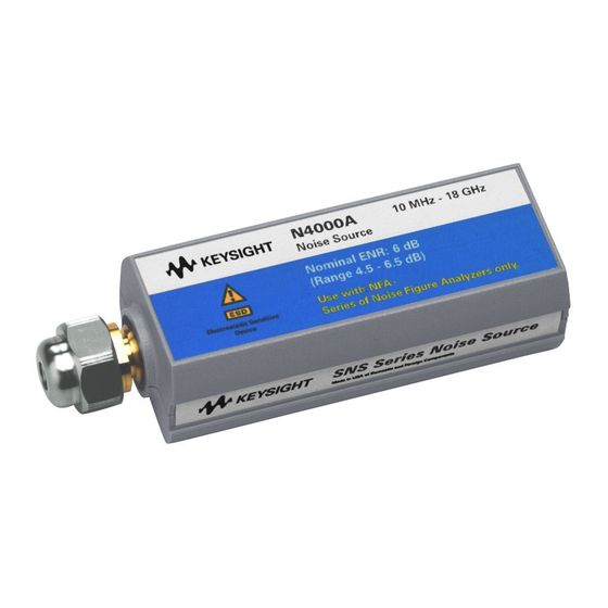
- Page 15 Keysight N4000/1/2A SNS Series Smart Noise Sources Operating and Service Manual Introduction Product Overview This chapter provides an overview of the Keysight N4000/1/2A SNS Series Smart Noise Sources.
-
Page 16: Introduction
Introduction Product Overview This manual contains operating and service information for the Keysight SNS series smart noise sources, consisting of models; N4000A, N4001A, and N4002A. The SNS series smart noise source, when commanded “Off” produces RF noise due to thermal agitation of its RF components at a level appropriate to its physical temperature. - Page 17 Keysight N4000/1/2A SNS Series Smart Noise Sources Operating and Service Manual Installation Handling Precautions Initial Inspection Service and Recalibration Equipment Supplied with the NFA Equipment Available but not Supplied This chapter provides you important information on how to check and prepare your instrument for operation.
-
Page 18: Installation
Technologies Service and Support Office. Refer to “Sales and Technical Support” on page 6 of this manual. Keysight Technologies will arrange for repair or replacement of the damaged or defective equipment. Keep the shipping materials for the carrier’s inspection. Keysight N4000/1/2A Operating and Service Manual... -
Page 19: Service And Recalibration
“Sales and Technical Support” on page 6 of this manual for the Keysight Technologies nearest to you. Attach a tag indicating the type of service required, return address, model number, and serial number. Mark the container FRAGILE to insure careful handling. In any correspondence, refer to the instrument by model number and serial number. -
Page 20: Options
Installation Options The Keysight N4000A and N4001A noise sources are available with Option 001, Type-N (male) output connector option. Since the Type-N connectors are not suitable for use above 18.0 GHz, no output connector option is available for the Keysight N4002A. Mating connectors The SNS series smart noise sources can be mated with other instrumentation having the connectors listed in... - Page 21 Keysight N4000/1/2A SNS Series Smart Noise Sources Operating and Service Manual Specifications General Specifications Environmental Conditions This chapter provides the specifications of the N4000/1/2A SNS Series Smart Noise Sources.
-
Page 22: Specifications General Specifications
Specifications General Specifications Specifications The specifications in Table 3-1 are performance standards or limits against which the SNS series smart noise source may be tested. These specifications for the noise source are ONLY valid if the analyzer has been allowed to meet its specified warm-up time. -
Page 23: Characteristic Swr At 23 °C
Specifications [a] ENR values are given at cardinal frequency points over the frequency range of each noise source. These values are stored within the noise source’s internal EEPROM and documented on the calibration report. [b] Maximum change in complex reflection coefficient between source ON and source OFF at all frequencies for N4000A only: 0.01. [c] For correct connector usage, refer Table A-2 for the torque settings. - Page 24 Specifications The uncertainty for each noise source can be unique to that noise source. The uncertainty will typically vary by less than 0.01 dB at any frequency between different noise sources produced in the same year when first produced. Subsequent calibrations must be performed at suitably capable calibration vendors in order to keep the uncertainties similar.
-
Page 25: Figure 3-2 Example Enr Uncertainty Versus Frequency For The N4000A Model
Specifications Figure 3-2 Example ENR uncertainty versus frequency for the N4000A model Figure 3-3 Example ENR uncertainty versus frequency for the N4001A and N4002A models Keysight N4000/1/2A Operating and Service Manual... -
Page 26: Supplemental Characteristics
Specifications Supplemental characteristics Table 3-2 Supplemental characteristics Characteristic N4000/1/2A ENR variation with temperature <0.01 dB/°C for 30 MHz to 26.5 GHz Range 0 to 55 °C Resolution 0.25 °C Temperature sensing accuracy – ±1° at 25 °C Accuracy – ±2° over 0 °C to 55 °C Physical specifications Table 3-3 Physical specifications... -
Page 27: Environmental Conditions
Specifications Environmental Conditions The instrument is designed for indoor use and in an area with low condensation. The table below shows the general environmental requirements for this instrument. Environmental cond ition Requirement Operating condition – 0 °C to 55 °C Temperature Storage/shipment condition –... - Page 28 Specifications THIS PAGE HAS BEEN INTENTIONALLY LEFT BLANK. Keysight N4000/1/2A Operating and Service Manual...
- Page 29 Keysight N4000/1/2A SNS Series Smart Noise Sources Operating and Service Manual Operating Guide Operating Instructions Operator’s Maintenance Performance Tests Adjustments Replaceable Parts Service This chapter provides simple quick-check instructions to verify the N4000/1/2A SNS series smart noise source’s functionality prior to usage. It also provides information on service and maintenance of the N4000/1/2A.
-
Page 30: Operating Guide
Operating Guide Operating Instructions This section refers to operation with the Keysight NFA Series Noise Figure Analyzers. The Keysight SNS series smart noise sources work with these analyzers as well as other Keysight analyzers. For more detailed operating instructions, refer to the Keysight NFA Series Noise Figure Analyzers User’s Guide. -
Page 31: Operator's Check
Operating Guide All of the operator’s checks are performed using a Keysight Noise Figure Analyzer with firmware version A.01.01 and above. This can be used to perform an operational verification check. Operator’s check The operator’s checks in this section should be performed if failure of the SNS series smart noise source is suspected. -
Page 32: Figure 4-2 Operator's Check Test Setup For Data Communication
Operating Guide Figure 4-2 Operator’s check test setup for data communication 8 Press the ENR key. 9 Press the ENR Mode menu key and set it to ENR Mode (Table). 10 Press the Common Table menu key and set it to Common Table (On). 11 Press the ENR Table menu key. -
Page 33: Figure 4-3 A Typical Cleared Enr Table
15 Verify the data has been transferred from the SNS to the NFA. The data transfer should be similar to Figure 4-4 on page 34. If it is not, return the SNS to Keysight Technologies for repair. Keysight N4000/1/2A Operating and Service Manual... -
Page 34: Figure 4-4 A Typical Enr Table After Data Entry
Operating Guide Figure 4-4 A typical ENR table after data entry Operator’s check for T communication cold The following procedure checks that the SNS can transfer the T data to the cold NFA. 1 Remove any cables from the NFA input and SNS drive. 2 Press the Preset key. - Page 35 Operating Guide 5 Connect the SNS to the NFA Port using the multi-pin 11730 cable, as shown in Figure 4-5 on page 35. Figure 4-5 Operator’s check test setup for T communication cold 6 Press the SNS Tcold menu key and set it to SNS Tcold (Off). 7 Press the User Tcold menu key and set it to User Tcold (On).
-
Page 36: Figure 4-7 Typical User Value After Uploading Sns Value
Operating Guide Figure 4-6 Typical user value 8 Press the User Tcold From SNS menu key. In the User Value menu key, the new ambient temperature value is displayed. Figure 4-7 shows a typical NFA menu map. Figure 4-7 Typical user value after uploading SNS value Keysight N4000/1/2A Operating and Service Manual... - Page 37 Operator’s check for T upload from SNS cold 10 If the value does not change, return the SNS to Keysight Technologies for repair. Operator’s check for switching noise source off and on The following procedure checks that the SNS can switch the noise source off and on.
- Page 38 Operating Guide 3 Connect the SNS to the NFA Port using the multi-pin 11730 cable, as shown in Figure 4-9. Figure 4-9 SNS connected to NFA graphic 4 Press the Frequency/Points key. 5 Press the Frequency Mode menu key. 6 Press the Fixed menu key. 7 Press the Fixed Frequency menu key.
-
Page 39: Figure 4-10 Typical Example Of Power Reading With Noise Source On
Operating Guide Figure 4-10 Typical example of power reading with Noise Source On 14 Press the Noise Source menu key and set it to Noise Source (Off). 15 Monitor the power value which appears in the manual measurement screen. Figure 4-11 on page shows a typical example of this. -
Page 40: Figure 4-11 Typical Example Of Power Reading With Noise Source Off
Operating Guide Figure 4-11 Typical example of power reading with Noise Source Off 16 If there is no change in value, return the SNS to Keysight Technologies for repair. Keysight N4000/1/2A Operating and Service Manual... -
Page 41: Operator's Maintenance
Operating Guide Operator’s Maintenance Proper connector care is a vital part of the maintenance which should be performed by the user. The life of the connector can be greatly extended by following the general connector care practices outlined in “Appendix A: Caring for Connectors”... -
Page 42: Replaceable Parts
Operating Guide Replaceable Parts Table 4-1, Table 4-2, and Table 4-3 list all replaceable parts available for the Keysight N4000/1/2A SNS series smart noise source. Figure 4-12 shows a typical SNS series smart noise source being prepared for parts replacement at the assembly level by removing the four end screws (two at each end). - Page 43 Operating Guide Table 4-3 Chassis parts Keysight part Reference Model Description number designator N4000A, N4001A, N4002A E9321-20002 MP1, MP2 Machined casting N4000A, N4001A, N4002A E9321-00001 MP3, MP4 Shield N4000A, N4001A, N4002A E9321-40001 MP5, MP6 Plastic shell N4000A, N4001A, N4002A 0460-1919 MP7, MP8 Copper roll shielding tape N4000A, N4001A, N4002A...
-
Page 44: Figure 4-12 Illustrated Parts Breakdown
Operating Guide Figure 4-12 Illustrated parts breakdown Keysight N4000/1/2A Operating and Service Manual... -
Page 45: Figure 4-13 Sns Series Smart Noise Source Block Diagram
Operating Guide Figure 4-13 SNS series smart noise source block diagram Keysight N4000/1/2A Operating and Service Manual... -
Page 46: Service
Operating Guide Service Principles of operation Referring to the SNS block diagram in Figure 4-13 on page 45, a constant +28 V is supplied from the NFA through the multi-pin “Connector” block when the SNS is connected to the noise figure analyzer. A voltage inverter is used in the N4000A and N4001A to input approximately –25 V to the current regulator. -
Page 47: Repair Of Defective Noise Source
Operating Guide Repair of defective noise source Repair by the user is not recommended because of the complex equipment required for test and calibration. However, a number of replacement parts are available for customers with repair and calibration capabilities. See “Replaceable Parts”... -
Page 48: Reassembly Procedure
44. 2 Snap the plastic shells together. Returning the SNS series smart noise source for calibration When returning the N4000/1/2A to Keysight Technologies for calibration, send it to your nearest Keysight Sales and Service Office. Refer to “Sales and Technical Support”... -
Page 49: Enr File Format
Keysight N4000/1/2A SNS Series Smart Noise Sources Operating and Service Manual ENR File Format Format Details Viewing the Smart Noise Source ENR Data Examples This chapter explains the format of an ENR file. -
Page 50: Format Details
ENR File Format Format Details An SNS ENR file: – includes all data currently supplied on the printed noise source calibration report. – can be viewed and edited using a standard text editor (for example Wordpad). – is simple to create and interpret. –... - Page 51 ENR File Format – The FieldName and OptionalValue, if present, must be separated by whitespace. – Whitespace following the ‘]’ is ignored. – The file must start with one or more header fields (ignoring comments and blank lines). All header fields must appear at the beginning of the file before the ENR data records.
- Page 52 ENR File Format Table 5-2 Optional header fields FieldName Description OptionalValue Description Example The serial number of A string containing the Serialnumber the SNS series smart serialtext [Serialnumber 3318A14223] serial number noise source Identifies the SNS series smart noise Model modelcode Model code string [Model N4000A]...
-
Page 53: Enr Data
ENR File Format ENR data ENR data records must be ordered from the lowest to the highest frequency. General form The noise figure analyzer attempts to interpret lines which are not comments or header fields as ENR data. ENR data has the general form: Freq [Funit] ENR [Eunit] [Euncert [on_mag on_phase off_mag off_phase [on_mag_uncert [on_phase_uncert off_mag_uncert off_phase_uncert]]]]... - Page 54 ENR File Format The ENR unit field (Eunit) is optional. The default unit is dB. Currently, the only allowed unit is dB. Note that units K, C, F (temperature) are reserved for possible future use, but are not supported by the noise figure analyzer at this time. The uncertainty field for the ENR amplitude (Euncert) is optional.
-
Page 55: Viewing The Smart Noise Source Enr Data
ENR File Format Viewing the Smart Noise Source ENR Data To view the ENR data you need a noise figure analyzer and a diskette. For an explanation of saving a file to a diskette using the NFA, see the Noise NOTE Figure Analyzer User’s Guide. -
Page 56: Examples
ENR File Format Examples Example 1 This first example shows a simple ENR file where the Frequency and ENR values have been entered manually into the noise figure analyzer: # ENR Data File # Created by N8973A Keysight NFA Series Noise Figure Analyzer # Serial Number GB40390000 Firmware Revision A.01.01 # 13:37:07 Mar 28, 2001 # Format is: Frequency (Hz), ENR (dB) -
Page 57: Example 2
ENR File Format Example 2 The second example is an SNS ENR file saved to a diskette: # ENR Data File # Created by N8975A NFA Series Noise Figure Analyzer # Serial Number GB40390000 Firmware Revision A.01.01 # 13:37:07 Mar 28, 2001 # Format is: Frequency (Hz), ENR (dB), ENR Unc (dB), # On Refl.Mag (lin), On Refl.Phase (deg), # Off Refl.Mag (lin), Off Refl.Phase (deg),... - Page 58 ENR File Format 7000000000,14.895,0.180,0.0430,-37.0,0.0430,-27.0,0.0079,-2.3,0.0049, -2.3 8000000000,15.016,0.198,0.0232,-160.3,0.0232,-160.3,0.0091,-3.8,0.0053, -1.8 9000000000,15.134,0.201,0.0122,+71.4,0.0122,+71.4,0.0037,+17.3,0.0057, +7.3 10000000000,15.253,0.194,0.0080,+116.2,0.0080,+116.2,0.0048,-1.4,0.0056 ,-5.4 11000000000,15.249,0.243,0.0241,+65.7,0.0241,+65.7,0.0059,+1.5,0.0049, +44.5 12000000000,15.349,0.240,0.0196,+8.8,0.0196,+8.8,0.0057,+3.2,0.0077, +2.2 13000000000,15.383,0.188,0.0217,-5.4,0.0217,-5.4,0.0062,-6.9,0.0045, -1.9 14000000000,15.355,0.178,0.0228,-66.6,0.0228,-66.6,0.0075,+11.2,0.0065, +1.2 15000000000,15.367,0.187,0.0141,+141.6,0.0141,+141.6,0.0036,-3.2,0.0029 ,-1.2 16000000000,15.421,0.182,0.0251,+6.4,0.0251,+6.4,0.0030,+7.2,0.0042, -1.2 17000000000,15.418,0.174,0.0242,-100.5,0.0242,-100.5,0.0048,-2.7,0.0050 ,+9.7 18000000000,15.464,0.179,0.0183,+124.4,0.0183,+124.4,0.0098,-1.1,0.0100 ,+9.1 The values shown in Example 2 are representative of their position in the file. NOTE Therefore, they may not be numerically accurate.
-
Page 59: Caring For Connectors
Keysight N4000/1/2A SNS Series Smart Noise Sources Operating and Service Manual Caring for Connectors Introduction Visual Inspection Cleaning Mechanical Inspection: Connector Gages Mechanical Specifications Using Connector Gages Making Connections Adapters Principles of Microwave Connector Care The material contained in this appendix may not apply to the connector you are using on the instrument. -
Page 60: Introduction
Caring for Connectors Introduction Recent advances in measurement capabilities have made connectors and connection techniques more important than ever before. Damage to the connectors on calibration and verification devices, test ports, cables, and other devices represent an increasing burden in downtime and expense. This Appendix will help you get the best performance from all coaxial microwave connectors: –... -
Page 61: Visual Inspection
Caring for Connectors Visual Inspection Visual inspection and, if necessary, cleaning should be done every time a connection is made. Metal and metal by-product particles from the connector threads often find their way onto the mating plane surfaces when a connection is disconnected and even one connection made with a dirty or damaged connector can damage both connectors beyond repair. -
Page 62: Precision 7 Mm Connectors
Caring for Connectors If a connector shows deep scratches or dents, particles clinging to the mating plane surfaces, or uneven wear, clean it and inspect it again. Damage or defects like dents or scratches, which are deep enough to displace metal on the mating plane surface of the connector, may indicate that the connector itself is damaged and should not be used. -
Page 63: Sexed Connectors
Caring for Connectors Sexed connectors On sexed connectors, especially precision 3.5 mm and SMA connectors, pay special attention to the female center conductor contact fingers (Figure A-2 Figure A-3). These are very easily bent or broken, and damage to them is not always easy to see. -
Page 64: Cleaning
Caring for Connectors Cleaning Careful cleaning of all connectors is essential to assure long, reliable connector life, to prevent accidental damage to connectors, and to obtain maximum measurement accuracy and repeatability. Yet it is the one step most often neglected or done improperly. Supplies recommended for cleaning microwave connectors are as follows: –... -
Page 65: Precision 7 Mm Connectors
Caring for Connectors Carefully avoid wetting the plastic support bead (which is easily damaged by alcohol) inside the connector and blow the connector dry immediately with a gentle stream of compressed air. Precision 7 mm connectors When precision 7 mm connectors have been cleaned with the center conductor collet removed, insert the collet and clean the mating plane surfaces again. -
Page 66: Drying Connectors
Caring for Connectors Figure A-4 Cleaning interior surfaces Metal must never be used (it will scratch the plated surfaces), and in cleaning NOTE precision 3.5 mm connectors the diameter must not exceed 0.070 in. (1.7 mm). The wooden handle of a cotton swab, for example, is too large for this purpose. Even though the handle can sometimes be inserted into the connector, even when wrapped in lint-free cloth, movement of the handle against the center conductor can exert enough force on the center conductor to damage it... -
Page 67: Mechanical Inspection: Connector Gages
Caring for Connectors Mechanical Inspection: Connector Gages Even a perfectly clean, unused connector can cause problems if it is mechanically out of specification. Since the critical tolerances in microwave connectors are on the order of a few ten-thousandths of an inch, using a connector gage is essential. Before using any connector for the first time, inspect it mechanically using a connector gage. -
Page 68: Mechanical Specifications
Caring for Connectors Mechanical Specifications The critical dimension to be measured, regardless of connector type, is the position (generally, the recession or setback) of the center conductor relative to the outer conductor mating plane. Mechanical specifications for connectors specify a maximum distance and a minimum distance that the center conductor can be positioned behind (or, in female Type-N connectors, in front of) the outer conductor mating plane. -
Page 69: Sexed Connectors
Caring for Connectors Sexed connectors In Type-N and precision 3.5 mm connectors, the position of the center conductor in the male connector is defined as the position of the shoulder of the male contact pin — not the position of the tip. The male contact pin slides into the female contact fingers and electrical contact is made by the inside surfaces of the tip of the female contact fingers on the sides of the male contact pin. -
Page 70: Ω Type-N Connectors
Caring for Connectors Therefore the mechanical specifications of Type-N connectors give a maximum protrusion of the female contact fingers in front of the outer conductor mating plane and a minimum recession of the shoulder of the male contact pin behind the outer conductor mating plane. -
Page 71: Using Connector Gages
Caring for Connectors Using Connector Gages Before a connector gage is used, it must be inspected, cleaned, and zeroed. Inspecting and cleaning the gage Inspect the connector gage and the gage calibration block carefully, exactly as you have inspected the connector itself. Clean or replace the gage or the block if necessary (dirt on the gage or block will make the gage measurements of the connectors inaccurate and can transfer dirt to the connectors themselves, damaging them during gaging or when the connection is made). -
Page 72: Measuring Connectors
Caring for Connectors Figure A-6 Using the connector gage Gages should be checked often, to make sure that the zero setting has not NOTE changed. Generally, when the gage pointer on a gage that has been zeroed recently does not line up exactly with the zero mark, the gage or calibration block needs cleaning. - Page 73 Caring for Connectors Apply only enough pressure to the gage so that the gage pointer settles at a reading. Gently rock the connector gage within the connector, to make sure that the gage and the outer conductor have come together flatly. Read the recession (or protrusion) from the gage dial.
-
Page 74: Making Connections
Caring for Connectors Making Connections Making good connections is easy if a few simple principles are kept in mind: – All connectors must be undamaged, clean, and within mechanical specification. – The connectors must be precisely aligned with one another and in flat physical contact at all points on the mating plane surfaces. -
Page 75: To Make A Preliminary Connection
Caring for Connectors To make a preliminary connection Align the two connectors carefully and engage the connector nut over the exposed connector sleeve threads on the other connector. Gently turn the connector nut until a preliminary connection is made. Let the connector nut pull the two connectors straight together. - Page 76 Caring for Connectors Hold the torque wrench lightly by the knurled end of the handle only. Apply force at the end of the torque wrench only, perpendicular to the wrench and always in a plane parallel to the outer conductor mating planes. This will result in torque being applied to the connection through the wrench until the break point of the wrench is reached.
-
Page 77: Disconnection
Caring for Connectors Disconnection Disconnect connectors by first loosening the connector nut that was tightened in order to make the connection. If necessary, use the torque wrench or an open-end wrench to start the process, but leave the connection finger tight. At all times support the devices and the connection to avoid putting lateral (bending) force on the connectors. -
Page 78: Adapters
Caring for Connectors Adapters Adapters are used to connect a device with one connector interface to a device or to test equipment that has another interface, or to reduce wear on connectors that may be difficult or expensive to replace. Reducing wear is possibly the most important use of adapters, especially when devices that have SMA connectors are being used. - Page 79 Caring for Connectors Table A-3 Adapters Type Description – Precision 7 mm/male 3.5 mm – Precision 7 mm/female 3.5 mm Precision 7 mm and Type-N – Precision 7 mm/male 50 Ω Type-N – Precision 7 mm/female 50 Ω Type-N – Male 3.5 mm/female 3.5 mm –...
-
Page 80: Principles Of Microwave Connector Care
Caring for Connectors Principles of Microwave Connector Care Table A-4 Principles of microwave connector care Handling and storage DO NOT – Keep connectors clean. – Touch mating plane surfaces. – Extend sleeve or connector nut. – Set connectors contact-end down. –... - Page 81 This information is subject to change without notice. Always refer to the Keysight website for the latest revision. © Keysight Technologies 2001 - 2017 Edition 4, May 26, 2017 Printed in Malaysia *N4000-90009* N4000-90009 www.keysight.com...
Need help?
Do you have a question about the N4000A SNS Series and is the answer not in the manual?
Questions and answers